
KLIPSCH PERMANENT INSTALLATIONS
KI-102-SMA-II | KI-115-SMA-II | KI-172-SMA-II | KI-215-SMA-II | KI-262-SMA-II | KI-272-SMA-II | KI-362-SMA-II | KI-396-SMA-II
OWNER’S MANUAL
IMPORTANT SAFETY INSTRUCTIONS
1. READ these instructions.
2. KEEP these instructions.
3. HEED all warnings.
4. FOLLOW all instructions.
5. DO NOT use this apparatus near water.
6. CLEAN ONLY with dry cloth or lightly damped cloth.
7. DO NOT block any ventilation openings. Install in accordance
with the manufacturer’s instructions.
8. DO NOT install near any heat sources such as radiators, heat
registers, stoves, or other apparatus (including amplifiers)
that produce heat.
9. ONLY USE attachments/accessories specifically designed
for this application
10. USE only with a cart, stand, tripod, bracket, or table
specifically designed for this application, or sold with the
apparatus. When a cart is used, use caution when moving
the cart/apparatus combination to avoid injury from tip-over.
11. DO NOT expose this apparatus to dripping or splashing and ensure
that no objects filled with liquids, such as vases, are placed on
the apparatus.
12. DO NOT modify or alter in any way.
13. SWITCH OFF amplifier prior to connecting speakers.
14. DO NOT hang or suspend any items from this apparatus.
The exclamation point, within an equilateral triangle, is intended to
alert the user to the presence of important operating and maintenance
(servicing) instructions in the literature accompanying the product.
The lightning flash with arrowhead symbol within an equilateral
triangle, is intended to alert the user to the presence of
uninsulated “dangerous voltage” within the product’s enclosure that
may be of sufficient magnitude to constitute a risk of electrical shock
to persons.
WARNING: No naked flame sources – such as candles – should be placed
on the product.
WARNING: Neglect to follow the safety and installation instructions may
cause malfunctions resulting in property damage and personal injury
or death.
WARNING: Installation must be done by qualified personnel to
appropriate standards and/or building codes.
WARNING: Do Not Open! Risk of Electrical Shock. Voltages in this
equipment are hazardous to life. No user-serviceable parts inside. Refer
all servicing to qualified service personnel.
Klipsch recommends that only qualified personnel install its loudspeaker
systems. In addition to the load ratings of speaker enclosure pickup points,
rigging hardware and array configurations, the safety and integrity of any
installation depends on the strength and suitability of the attachment
location. At all times, make sure that the equipment and rigging point
locations are inspected and meet all load requirements with a large margin
of safety. Check all rigging components for defects and corrosion as per
their manufacturer’s recommendations.
Be sure that adequate safety factors are observed, including verifying the
load rating and stress capabilities of attachment hardware, including all
nuts, bolts, brackets and straps. Klipsch additionally recommends backup
retaining straps and/or cinched wirerope for an added measure of safety.
Installations and attachment locations that could present a safety harzard
should be checked and certified as safe by a professional structural engineer.
After assembly of the components on each speaker system, but before
operation, be sure that all bolts and nuts are double-checked for proper seating
and tightness. Due to the weight and size of the components involved, potential
damage could occur if devices were to become unattached.
The KI Series of products are for use
as a “Single Mount Array”, or SMA.
The suspension hardware is intended
for applications requiring suspension
of an individual loudspeaker.
The multiple suspension points are
available to add flexibility to the
mounting options, but NOT intended to
be used as suspension points for other
loudspeakers.

INSTALLATION
KI-102-SMA-II | KI-172-SMA-II
The optional SB-102 accessory bracket is specifically designed for the KI-102-SMA-II and
KI-172-SMA-II loudspeaker systems. The bracket provides up to four attachment points
to the securing surface and two attachment points to the speaker. When installing the
bracket, the attachement point (2” x 4” stud, Unistrut, “I” beam, etc.) must be made
with bolts that will securely hold the bracket to the mounting surface, which must be
load-rated to hold the speaker safely in place.
After the bracket is installed, mount the speaker to the bracket by first removing the
factory-attached screws on the top and bottom of the speaker. The bracket comes with
two 1/4” 20-thread knobs and washers, which will attach the bracket to the speaker. Slide
the speaker over the bracket and align the hole in the bracket with the threaded hole in
the speaker. Attach the knob screw and washer provided, and secure the screw. Do the
same to the bottom. Adjust the angle of the speaker to the desired location and tighten
both knob screws.
On the KI-172-SMA-II, additional internal mounting bolts are installed for the attachment
of readily available Omnimount
®
and other compatible brackets. Before completing
any installation using these devices, be sure that all hardware is firmly attached and
tightened, as recommended.
KI-102-SMA-II
KI-172-SMA-II

KI-262-SMA-II | KI-272-SMA-II | KI-362-SMA-II
KI-396-SMA-II | KI-115-SMA-II | KI-215-SMA-II
The KI-396-SMA-II, KI-362-SMA-II, KI-262-SMA-II utilize sixteen 3/8” -16 threaded
suspensions points with the KI-272-SMA-II and KI-115-SMA-II using twelve and four
suspension points respectively. The locations for these threaded mounting points
are compatible with readily available commercial rigging bars.
For the KI-115-SMA-II, Klipsch recommends use of the four rear panel suspension
points for face-down orientation.
Internal metal brackets that distribute the load to adjacent enclosure panels
back each individual mounting point.
Klipsch recommends that only professional-grade rigging components,
appropriately rated straight bolts and welded eye bolts are used. Additionally,
safety backup straps or wirerope should be installed for added measure of
rigging safety.
VISIT KLIPSCH.COM/PRO TO VIEW SPECIFICATION SHEETS FOR INDIVIDUAL FLY
POINT LOCATIONS BY MODEL.
KI-396-SMA-II
KI-215-SMA-II
KI-272-SMA-II
KI-362-SMA-II
KI-115-SMA-II
KI-262-SMA-II

ARRAY CONFIGURATIONS
EASE data is available on all KI series
speakers at KLIPSCH.COM/PRO. Klipsch
urges users to refer to this data when
determining how specific speaker systems
should be installed for optimum performance.
Although toed-out suggestions for coverage
patterns are suggested below, these
loudspeakers do not necessarily have to be
toed-out when installed in an array. There
can be pattern overlap, which will increase
output in that region, although with lobing
side effects.
NOTE: EACH SPEAKER SHOULD BE
SUSPENDED INDIVIDUALLY WHEN
FORMING THE LOUDSPEAKER ARRAY.
The KI-102-SMA-II, KI-362-SMA-II and
KI-396-SMA-II systems have horizontal
coverage patterns of 90º. The side panels
are angled at 22.5º, so two speakers tightly
aligned create a 45º angle between the axes.
As this accounts for only half of an individual
speaker’s total coverage angle, the speakers
would need to be toed-out to 90º (included
angle), to provide the smoothest pattern and
180º of total coverage.
The KI-262-SMA-II has a 60º coverage
pattern, with side panels angled at 22.5º. Two
enclosures tightly aligned create an angle of
45 degrees, and therefore would need to be
toed out an additional 15 degrees (included
angle) to form a 60º angle between axes,
creating 120º total coverage.
The KI-172-SMA-II and KI-272-SMA-II are
asymmetrical enclosures, and therefore offer
multiple mounting angle options. Note that
their coverage patterns are the same as the
KI-102-SMA-II and KI-262-SMA-II, respectively.
Please refer to the EASE data on
KLIPSCH.COM/PRO for specific coverage
pattern information on the KI-115-SMA-II and
KI-215-SMA-II low-frequency enclosures. The
KI-215-SMA-II matches the KI-362-SMA-II
enclosure form.
Klipsch recommends that power provided to the
speakers not exceed the values indicated in the
specifications by more than 3dB. If continuous
power or thermal ratings are exceeded, the
internal protective KLIP circuit will shut down the
high- or high/mid-frequency sections. These will
remain shutdown until input power is reduced
significantly. The KLIP circuit monitors continuous
average power. Although unlikely, it is possible to
create a situation where extreme transient signals
could damage componenet diaphragms before
triggering the KLIP protection circuit.
(KI-396-SMA-II does not feature KLIP circuit driver
protection) USE CAUTION WITH HIGH POWER!
Damage can also occur due to distortion generated
from underpowering, i.e. overdriving with too
little power. Klipsch recommends that amplifier
headroom be based on values 3dB above the
maximum speaker power ratings, or twice the
published numerical power rating of the speaker.
For example, the KI-102-SMA-II is rated at 200
watts continuous. A 3dB continuous headroom
factor would suggest a 400-watt amplifier.
POWER REQUIREMENTS
KI-362-SMA-II VARIPOINT™ ADJUSTMENT
The KI-362-SMA-II three-way loudspeaker system provides for
pattern adjustment by rotating the position of the high- and mid-
frequency VariPoint module. To accomplish this, first determine
the desired orientation of the Varipoint module. This should be
established before the speaker is suspended. While the speaker is
on its back, remove the eight #10 24-thread screws attaching the
high- and mid-frequency horn module to the front baffle. Rotate
the baffle to the desired position and reattach. Make sure that the
screws are fastened tightly. The module can be adjusted in 45º
increments, to eight possible positions.
DO NOT ATTEMPT THIS OPERATION WHILE THE
SPEAKER IS UPRIGHT!
10-24 UNC Screws
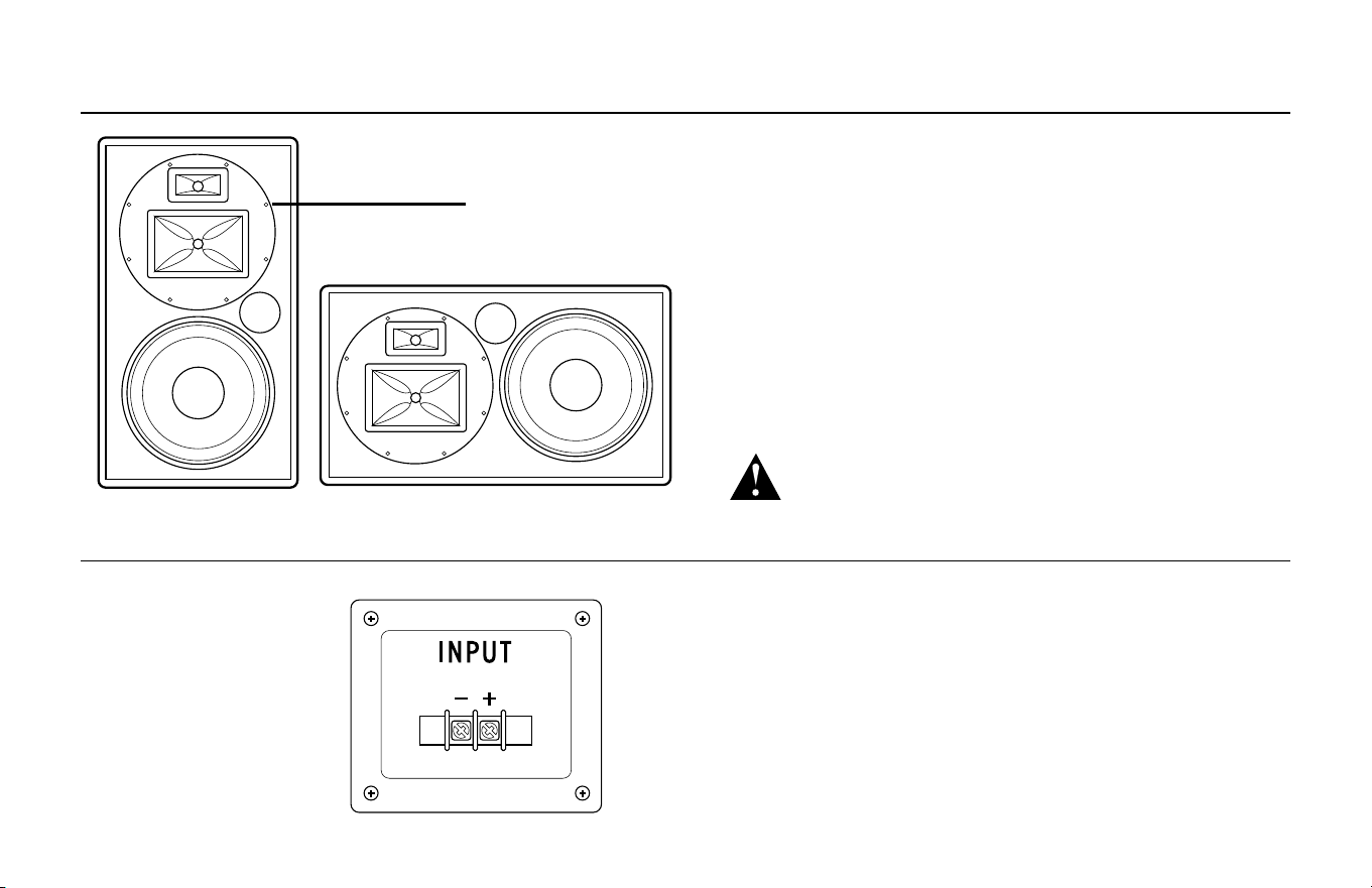
INPUT CONNECTIONS
All KI products feature a simple
2 pt. barrier strip input.

3502 WOODVIEW TRACE, INDIANAPOLIS, IN, USA
KLIPSCH.COM/PRO
©2015, Klipsch Group, Inc. Klipsch Group, Inc. is a wholly-owned subsidiary of Voxx International Corporation.
Klipsch and Keepers of the Sound are trademarks of Klipsch Group, Inc., registered in the United States and other countries. OmniMount is a registered trademark of Ergotron, Inc.
V08 - 0727