
MILWAUKEE ELECTRIC TOOL CORPORATION
13135 W. Lisbon Road, Brookeld, WI 53005
Drwg. 2
BULLETIN NO.
54-26-2703
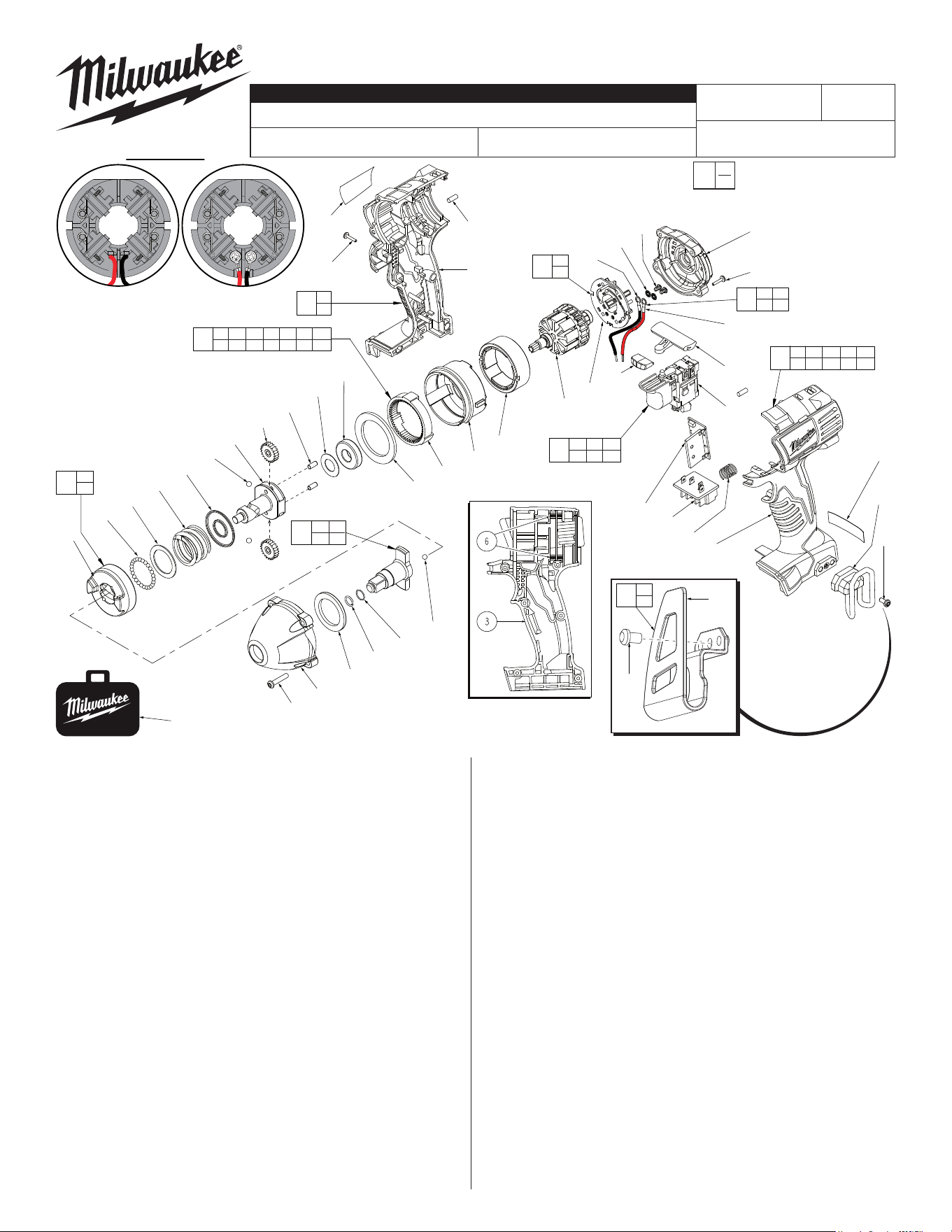
SERVICE PARTS LIST
FIG. PART NO. DESCRIPTION OF PART NO. REQ.
1 31-44-2435 Handle Assembly (1)
2 --------------- Left Handle Half (1)
3 --------------- Right Handle Half (1)
4 42-52-0062 End Cap (1)
5 45-24-0300 Forward / Reverse Shuttle (1)
6 45-30-0250 Rubber Slug (8)
7 42-70-5150 Belt Hook (1)
8 40-50-1090 Spring (1)
9 --------------- Contact Block (1)
10 23-66-2830 Switch (1)
11 23-66-1238 Switch/Brush Card Assembly (1)
13 --------------- LED Assembly (1)
15 --------------- Brush Card (1)
16 16-01-3010 Service Armature Assembly (1)
17 18-01-3011 Service Field (1)
18 --------------- PCB Assembly (1)
19 14-30-0920 Gear Box Assembly (1)
20 --------------- Rear Case (1)
21 --------------- Ring Gear (1)
22 --------------- Retaining Ring (1)
23 --------------- Ball Bearing (1)
24 --------------- Washer (1)
25 --------------- Pin (2)
26 --------------- Planet Gear (2)
27 --------------- Cam Shaft (1)
28 --------------- 3/16" Steel Ball (2)
29 --------------- Washer (1)
30 --------------- Compression Spring (1)
31 --------------- Washer (1)
32 --------------- 3.0mm Steel Ball (30)
33 --------------- Hammer (1)
36 42-06-0305 3/8" Square Drive Anvil Assembly (1)
CATALOG NO. 2651-20
REVISED BULLETIN
SPECIFY CATALOG NO. AND SERIAL NO. WHEN ORDERING PARTS
18 Volt 3/8" Square Impact Wrench
STARTING
SERIAL NO.
DATE
Aug. 2014
WIRING INSTRUCTION
B77D
EXAMPLE:
Component Parts (Small #)
Are Included When Ordering
The Assembly (Large #).
0
00
SEE PAGE 3
FIG. PART NO. DESCRIPTION OF PART NO. REQ.
37 44-90-1050 Hog Ring (1)
42 45-88-1317 Front Washer (1)
43 28-50-0900 Front Case Sub-Assembly (1)
47 06-82-7010 8-18 x 24 Pan Hd. Screw (4)
55 06-82-6350 M3 Pan Hd. T-10 Screw (7)
56 06-82-7336 M3 Pan Hd. T-10 Screw (4)
57 06-82-5275 6-32 x 5/16" Slt. Pan Hd. T-15 Screw (1)
59 12-20-2650 Service Nameplate Kit (1)
60 10-20-2695 Warning Label (1)
65 02-02-1300 5mm Steel Ball (1)
67 34-40-1885 Rubber Ring (1)
68 42-55-2650 Carrying Case (1)
70 23-66-1239 Switch and Housing Kit (1)
71 14-46-1710 Cam Shaft/Hammer Kit (1)
72 05-88-0928 M3 x 5mmPan Hd. T10 Screw (2)
73 45-88-1980 Spring Washer (2)
74 --------------- Leadwire Assembly - Red (1)
75 --------------- Leadwire Assembly - Black (1)
76 14-46-2395 Leadwire/Screw/Washer Kit (1)
77 14-46-2024 Brush Card Assembly (1)
80 42-70-2653 Belt Clip Assembly (1)
81 --------------- Belt Clip (1)
82 --------------- Belt Clip Screw (1)
54-26-2702
«
«
19
20 21 22 23 24 25 26
27 28 29 30 31 32 33
Place Rubber Slugs (6)
as shown, four in each
handle half (2,3).
1
2
3
11
9 10 13
15 18 76
27
33
71
70
2 3 6 9 10
13 15 18 55 76
60
7
57
18
80
81
82
81
82
There are
2 belt clip
designs for
this tool. Belt Clip #7,
42-70-5150 is dis-
continued and replaced
by Belt Clip Assembly
42-70-2653 (#80).
68
59
55
6
3
33
32
31
30
29
28
27
26
25
24
23
22
21
20
17
16
13
15
74
5
10
47
43
42
37
67
65
9
8
2
4
56
75
72
73
L
Soldered Screwed
#77 Two styles of Brush Card
Assemblies See Page Two
77
15
76
76
72 73
74 75
36
37 65
67
«
L
Soldered-
Original design
Screwed-
New design
Back View
Brush Card Assemblies
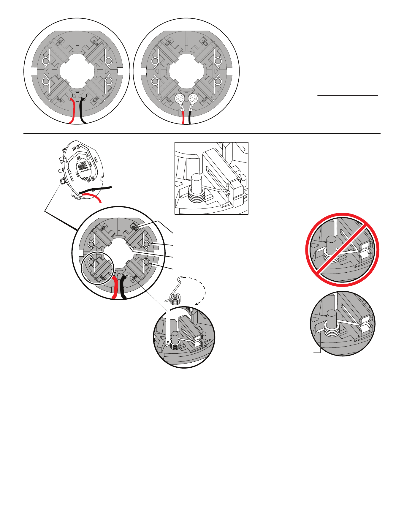
NOTE:
There are two Brush Card Assembly designs.
On the original brush card design the red and black wires
that go to the switch are soldered on the brush card.
On the new brush card design the red and black wires
that go to the switch are secured to the brush card with
spring washers and screws.
The new brush card design is directly interchangeable
in tools that have the old brush card design.
Be sure carbon
brush is in brush tube
with brush shunt moving
freely in side groove of tube.
Place brush spring over post with short leg
positioned downward as shown. Be sure spring
is completely down with short leg trapped against
'Y' shaped wall on brush card.
While holding spring in place, bring the long leg of
spring over the brush tube and through rear opening
of tube. Position rounded hook of spring in groove on
back of carbon brush. Be sure to check for free move-
ment between carbon brush, brush shunt and brush spring.
Brush Card Assy.
Brush Shunt (4 places)
Right Brush Spring (2x)
Carbon Brush (4x)
Left Brush Spring (2x)
Red
Black
Wrong
Correct
Short leg
of spring to
the bottom
NOTE:
As an aid to prevent damage to the armature
commutator or the brushes when removing and
installing the armature assembly, it is recommended to
pull the carbon brushes partially back into the brush
tube. The carbon brushes will be held in place with the
brush spring moving from the rear of the brush to the
side of the brush.
In the unlikely event that the spring pops off follow the
instructions below.
FIG. NOTES:
15,16,17 See service note and illustration on the back of bulletin to aid
with the removal and installation of the the Brush Card (15),
Armature (16) and Field (17).
17 Field (17) to be positioned with side cut-outs to the front.
20,21 Position Ring Gear (21) with three lugs face down to interlock
in the bottom of Rear Case (20).
20,43 Be sure to match the raised contours on the bottom of Rear
Case (20) with raised contour on bottom of Front Case (43)
when assembling.
29,30 Make sure concave side of Washer (29) faces Spring (30).
42,43 Tappered end of Front Washer (42) to face Front Case (43).
FIG. LUBRICATION
(Type 'J' Grease, No. 49-08-4220):
21,26 Lightly coat I.D. of the Ring Gear (21) and center of the two
Planet Gears (26) with grease.
27 Place a dab of grease in the ball grooves of the Cam
Shaft (27).
36,37 Lightly coat front washer surface of Anvil (36) with grease,
place a dab in the Ball holes of Anvil and in Needle Bearing
inside the Anvil.
43 Coat inside grooves of Bushing (inside of 43) with grease.
L
Soldered-
Original design
Screwed-
New design
Back View
Brush Card Assemblies
NOTE:
There are two Brush Card Assembly designs.
On the original brush card design the red and black wires
that go to the switch are soldered on the brush card.
On the new brush card design the red and black wires
that go to the switch are secured to the brush card with
spring washers and screws.
The new brush card design is directly interchangeable
in tools that have the old brush card design.
Be sure carbon
brush is in brush tube
with brush shunt moving
freely in side groove of tube.
Place brush spring over post with short leg
positioned downward as shown. Be sure spring
is completely down with short leg trapped against
'Y' shaped wall on brush card.
While holding spring in place, bring the long leg of
spring over the brush tube and through rear opening
of tube. Position rounded hook of spring in groove on
back of carbon brush. Be sure to check for free move-
ment between carbon brush, brush shunt and brush spring.
Brush Card Assy.
Brush Shunt (4 places)
Right Brush Spring (2x)
Carbon Brush (4x)
Left Brush Spring (2x)
Red
Black
Wrong
Correct
Short leg
of spring to
the bottom
NOTE:
As an aid to prevent damage to the armature
commutator or the brushes when removing and
installing the armature assembly, it is recommended to
pull the carbon brushes partially back into the brush
tube. The carbon brushes will be held in place with the
brush spring moving from the rear of the brush to the
side of the brush.
In the unlikely event that the spring pops off follow the
instructions below.
FIG. NOTES:
15,16,17 See service note and illustration on the back of bulletin to aid
with the removal and installation of the the Brush Card (15),
Armature (16) and Field (17).
17 Field (17) to be positioned with side cut-outs to the front.
20,21 Position Ring Gear (21) with three lugs face down to interlock
in the bottom of Rear Case (20).
20,43 Be sure to match the raised contours on the bottom of Rear
Case (20) with raised contour on bottom of Front Case (43)
when assembling.
29,30 Make sure concave side of Washer (29) faces Spring (30).
42,43 Tappered end of Front Washer (42) to face Front Case (43).
FIG. LUBRICATION
(Type 'J' Grease, No. 49-08-4220):
21,26 Lightly coat I.D. of the Ring Gear (21) and center of the two
Planet Gears (26) with grease.
27 Place a dab of grease in the ball grooves of the Cam
Shaft (27).
36,37 Lightly coat front washer surface of Anvil (36) with grease,
place a dab in the Ball holes of Anvil and in Needle Bearing
inside the Anvil.
43 Coat inside grooves of Bushing (inside of 43) with grease.
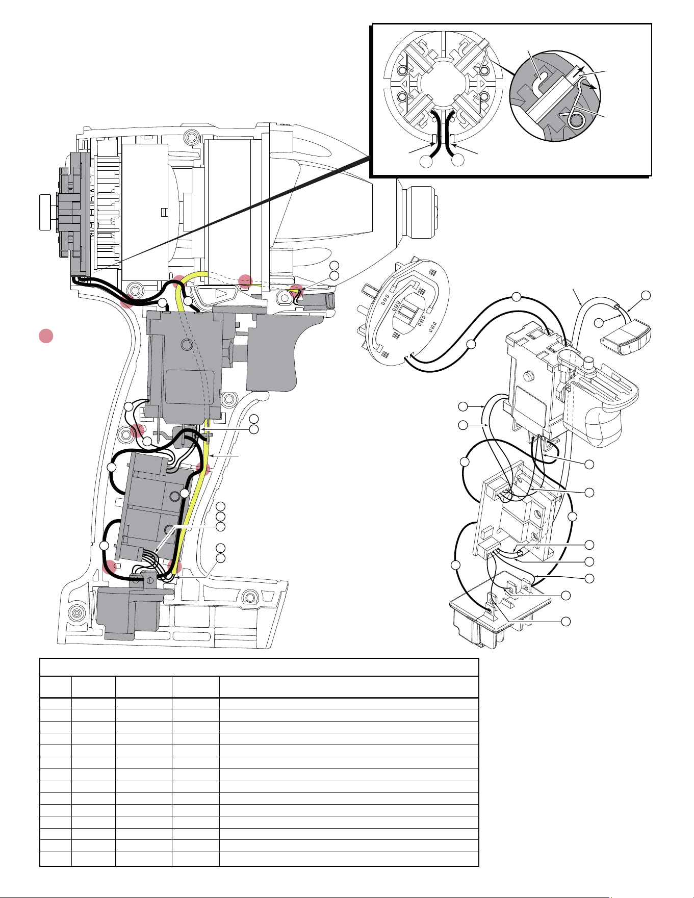
= WIRE TRAPS
or GUIDES
13
3
4
5
2
1
14
13
14
12
11
10
7
9
6
8
Sleeve
Black
Brown
Orange
White
Black
Blue
Red
Yellow
Blue
Red
Brown
Green
BRUSH CARD
ASSEMBLY
LED
SWITCH
PCBA
TERMINAL
BLOCK
ASSEMBLY
Red
Black
3
4
5
2
1
13
14
7
9
8
6
13
14
Sleeve
10
14
11
12
AS AN AID TO REASSEMBLY, TAKE
NOTICE OF WIRE ROUTING AND
POSITION IN WIRE GUIDES AND
TRAPS WHILE DISMANTLING TOOL.
BE CAREFUL AND AVOID PINCHING
WIRES BETWEEN HANDLE HALVES
WHEN ASSEMBLING.
BRUSH
SPRING
SHUNT
CARBON
BRUSH
WIRE
TRAP
WIRE
TRAP
2
1
BRUSH CARD ASSEMBLY
(BACK VIEW)
NOTE: Before attempting to remove armature or brush card assembly-
Pull brush back until the brush spring slides from the back of the brush, onto the
side of the brush as shown. (Do this to all four brushes). This will hold brushes
out of the way for ease of servicing and will help prevent damage to the carbon
brushes and the commutator of the armature.
To reinstall components, orient the Field with the cut-outs facing forward, place
the Armature into the Field prior to assembling onto the Brush Card Assembly.
Make sure that all brushes are returned to the proper position once Brush Card,
Armature and Field are properly seated in the Left Handle Half.
Be sure to place black wire #1 and red wire #2
rmly in the wire traps on the bottom of brush
card to prevent pinching between handle halves
and end cap.
Model 2650-20 shown
1 Black ----- ----- Component of Brush Card Assy. Connect to M2 on Switch.
2 Red ----- ----- Component of Brush Card Assy. Connect to M1 on Switch.
3 Red ----- ----- Component of Switch/Brush Card/Terminal Block Assembly.
4 Black ----- ----- Component of Switch/Brush Card/Terminal Block Assembly.
5 Brown ----- ----- Component of Switch/Brush Card/Terminal Block Assembly.
6 Orange ----- ----- Component of Switch/Brush Card/Terminal Block Assembly.
7 Green ----- ----- Component of Switch/Brush Card/Terminal Block Assembly.
8 White ----- ----- Component of Switch/Brush Card/Terminal Block Assembly.
9 Brown ----- ----- Component of Switch/Brush Card/Terminal Block Assembly.
10 Black ----- ----- Component of Switch/Brush Card/Terminal Block Assembly.
11 Blue ----- ----- Component of Switch/Brush Card/Terminal Block Assembly.
12 Red ----- ----- Component of Switch/Brush Card/Terminal Block Assembly.
13 Blue ----- ----- Component of Switch/Brush Card/Terminal Block Assy. (LED)
14 Yellow ----- ----- Component of Switch/Brush Card/Terminal Block Assy. (LED)
Terminals, Connectors and 1 or 2 End Wire Preparation
Wire
Color
Origin or
Gauge
Wire
No.
Length
WIRING SPECIFICATIONS