USER MANUAL
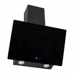
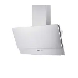
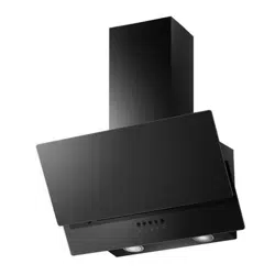
ANGLED GLASS AND STEEL DESIGNER
CHIMNEY COOKER HOOD
eiQCHFGBSS60/ eiQCHFGBSS90
Thank you for choosing electriQ
Please read this user manual before using this
product and keep it safe for future reference.
Visit our page www.electriQ.co.uk for our entire product range

2
CONTENTS
SAFETY
3
PRODUCT OVERVIEW
5
VENTING OPTIONS
6
INSTALLATION
7
FILTER OPTIONS
13
OPERATION
14
CLEANING AND MAINTENANCE
15
LIGHT REPLACEMENT
16
TROUBLESHOOTING
16
PRODUCT FICHE
17
SUPPORT
19

3
SAFETY PRECAUTIONS
Whilst this product is compliant with all safety requirements, incorrect
or inappropriate use can lead to both personal injury and potential
damage to property. Please read the contents of this instruction
booklet thoroughly before fitting or using this appliance.
• The cooker hood must be installed in accordance with the
installation instructions and all measurements followed.
• All installation work must be carried out by a competent person or
qualified electrician.
• The unit must be connected to an earthed power supply.
• If venting externally, make sure the ducting has no bends sharper
than 90 degrees as this will reduce the efficiency of the cooker
hood.
• The cooker hood is for domestic use only and is not designed for
commercial use. It should only be used for the purpose it was
intended – to extract vapours and cooking odours.
• Do not flambé or use an open flame under the cooker hood.
• Do not try to use the cooker hood without the grease filters or if the
filters are excessively greasy. They should be cleaned regularly
(see “Maintenance”) or replaced as necessary.
• The extraction fan must be level to avoid grease collection at one
end, as this could cause a potential fire risk.
• Do not leave frying pans unattended during use because
overheated fat or oils might catch fire.
• If the cooker hood is damaged, do not attempt to use it.
• If the supply cord is damaged, it must be replaced by the
manufacturer, its service agent or a similarly qualified person in
order to avoid a hazard.
• This appliance can be used by children aged from 8 years and
above and persons with reduced physical, sensory or mental
capabilities or lack of experience and knowledge if they have been
given supervision or instruction concerning use of the appliance in
a safe way and understand the hazards involved.
• Children shall not play with the appliance. Cleaning and user
maintenance shall not be made by children without supervision.
• Children should be supervised to ensure that they do not play with
the appliance. It is not a toy.

4
• The plug must be accessible after installation for isolation in case
of an emergency – or an appropriate fused switch if the unit is
hard-wired to the mains via a spur.
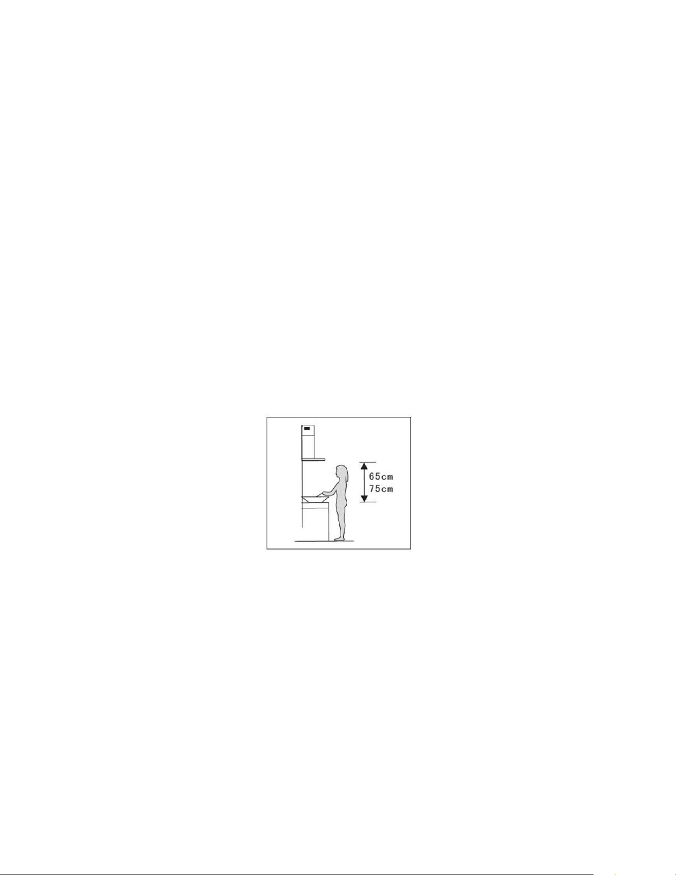
• The minimum distance between the surface of the hob and the
lowest part of the hood should be at least 65cm. A distance of
between 65cm and 75cm gives peak efficiency.
• The air must not be discharged into a flue that is used for
exhausting fumes from appliances burning gas or other fuels.
• When the hood is vented externally and used with appliances
which burn fuel (e.g. gas, oil, wood) the area must be sufficiently
ventilated to ensure safe operation. Fresh air must be allowed to
freely enter the room to prevent a partial vacuum.
• A partial vacuum can starve the heating appliance of oxygen,
impairing combustion. It can also prevent toxic fumes from leaving
the room, or can cause fumes to be sucked into the room from
outside.
• Safe operation is only possible when the partial vacuum within the
working area does not exceed 4 Pa (0.04 mbar). This can be
achieved by ensuring air is able to enter the room from outside
through a suitable sized opening which cannot be sealed during
operation. A number of alternative solutions are available to ensure
this. If in any doubt, professional advice should be sought.
• Regulations concerning the discharge of air have to be fulfilled.
• There is a potential fire risk if cleaning is not carried out in
accordance with the instructions.
• Clean your appliance periodically by following the method given in
the chapter MAINTENANCE
• If used in recirculation mode, the charcoal filters trap odours and
must be replaced at least once a year depending on how frequently
the cooker hood has been used.
• For safety reasons, please use only the same size of fixing or
mounting screw, which are recommended in this instruction
manual.
• Warning: Failure to install the screws or fixing device in accordance
with these instructions may result in electrical hazards
CAUTION: Accessible parts of the hood can become
very hot during use with cooking appliances, whether in use
or not, due to heat rising from the hob. Sufficient time should
be allowed for the unit to cool before touching either the
housing or the grease filters
5
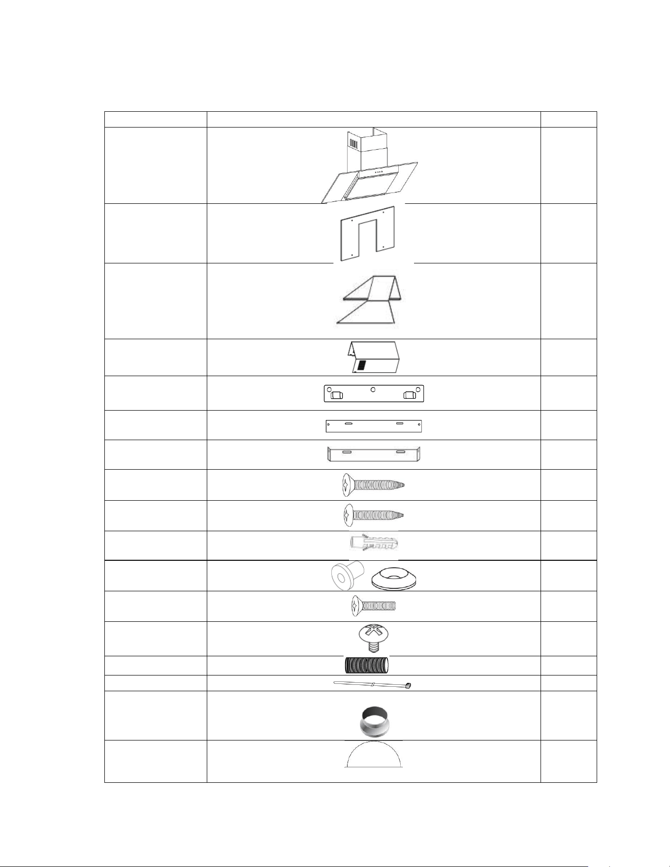
PRODUCT OVERVIEW - PARTS SUPPLIED
Description
Illustration
Qty.
Cooker hood
1
glass
1
Outer chimney
1
Inner chimney
1
Wall bracket
1
Plate I
1
Płate II
1
Screw
(4mm x 40mm)
7
Screw
(4mm x 30mm)
2
Wall plug
9
Rubber
cushion
4
Screw
4x25mm
4
Screw
(4mm x 8mm)
4
Exhaust Pipe
1
cable tie
1
Adaptor
1
Air Flaps
2
6
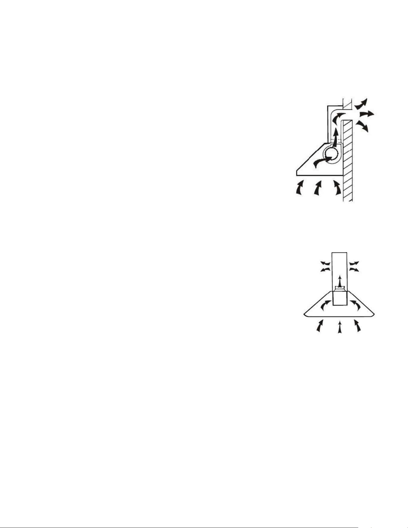
EXTERNAL VENTING
If you have an outlet to the outside, your cooker hood can be
connected as shown in the diagram using any suitable
extraction duct (enamel, aluminium, flexible pipe or
inflammable material with an interior diameter of 150mm) can
be used.
An adaptor is supplied to enable you to connect your hood to
pre-existing 120mm diameter ducting.
If this is the chosen installation method consideration to the
route of the vent pipe should be made prior to installation.
RECIRCULATION
This cooker hood also supports the recirculation of air once it has passed
through the filters. The filtered air is then expelled through the
vent holes in the side of the chimney.
When setting the unit up in this configuration, carbon filters
should also be used to remove odours from the air. Details of
sourcing and fitting the filters can be found in the Carbon filter
section.
When setting up for recirculation the installation instructions
should be followed, but a vent pipe should not be attached, and instead the air
can be routed back into the room through the top of the unit.
7
UNPACKING YOUR APPLIANCE
• Please take great care when unpacking; a sharp blade should not be used to
open the box, as it may go deep enough inside to damage components.
Components damaged or marked by careless unpacking are not covered under
the guarantee.
• Carefully unpack the contents and check against the section below (Parts) and
the next section (Product overview).
• Packaging materials should be recycled in accordance with local regulations
INSTALLATION
1. Before installation, ensure you have not connected the appliance to the mains
supply.
2. The cooker hood should be placed at a distance of 65~75cm above the
cooking plane for best effect.
Pic 1
8
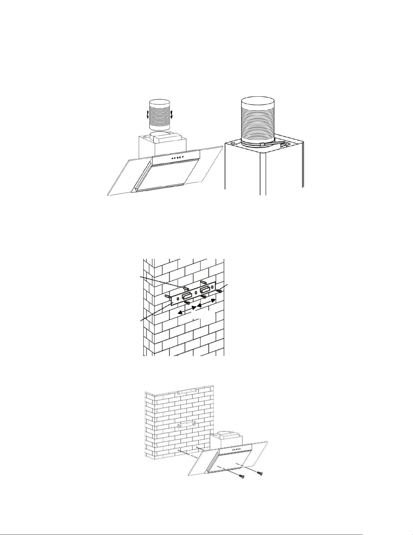
3. Insert the glass into the panel glove of
the cooker hood, then use 4 screws (4 x
25mm), inserting them through the 4 x
rubber cushions to fix the glass into the
cooker hood (see diagrams).
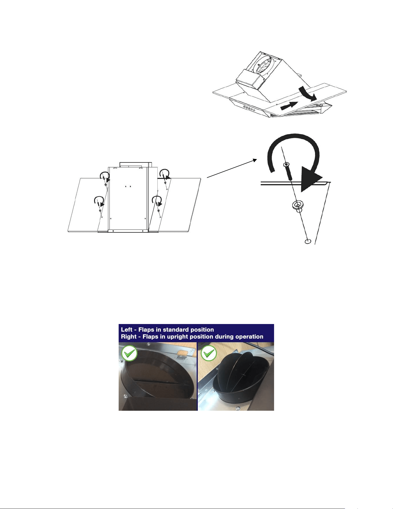
4. The 2 x air flaps should be installed at this stage, as access is easier before
the unit is wall mounted. On the top of the Hood Unit itself, where the air outlet
vent is located, the 2 x flaps should be carefully installed, bending very slightly so
the lugs at each end locate into the holes, enabling flaps to pivot upwards when
the unit is in operation, opening up the outlet fully for the air to pass through.
Please note: the small spindles/lugs at each end of each flap locate into the
holes on the housing, not the grooves above them:
9
5. Attach the exhaust pipe onto the outlet as shown below, and fix the pipe on the
outlet by cable tie. The adaptor can be used at this stage, if you already have
existing smaller diameter venting in place to connect.
6. Drill 3 holes to accommodate the wall bracket. Screw and tighten the wall
bracket onto the wall with the screws (4mm x 40 mm) and wall plugs provided.
7. Hang the appliance onto the wall bracket. Also, fix the cooker hood on the
wall by two 4x 30mm screws and wall plugs through the back of the cooker hood.
Screw
(4mm x 40mm)
Wall plug
Wall bracket
10
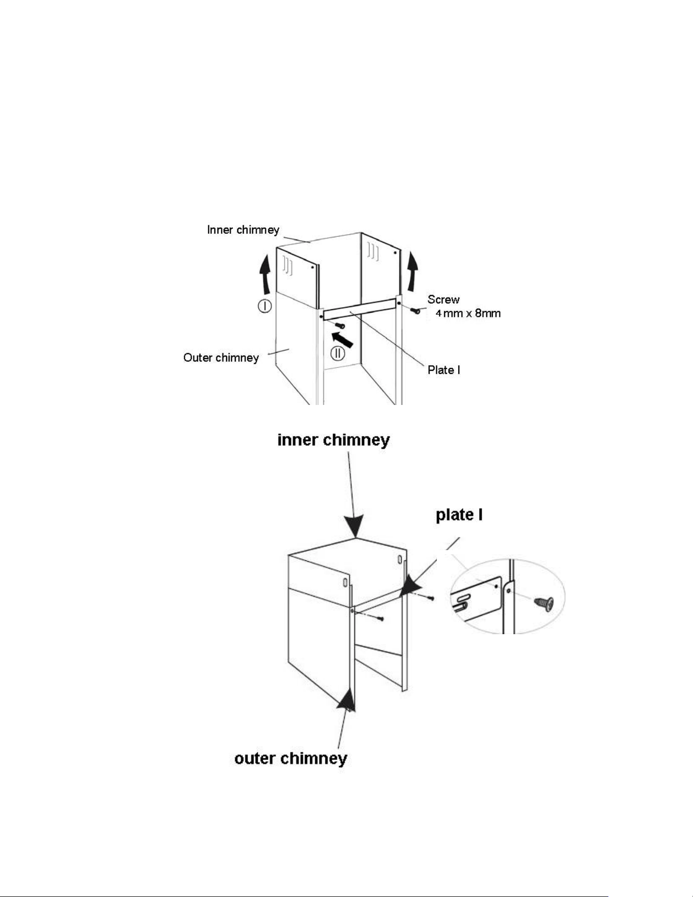
8. Put the inner chimney on the outer chimney. Install plate I on the chimney by
two screws (4 mm x 8mm). Drill holes on the wall to accommodate plate I.
NOTE: Remember not to fix the screws (4 mm x 8mm) too tightly; 1mm loose is
recommended, so that later height adjustment can be done more easily.
11
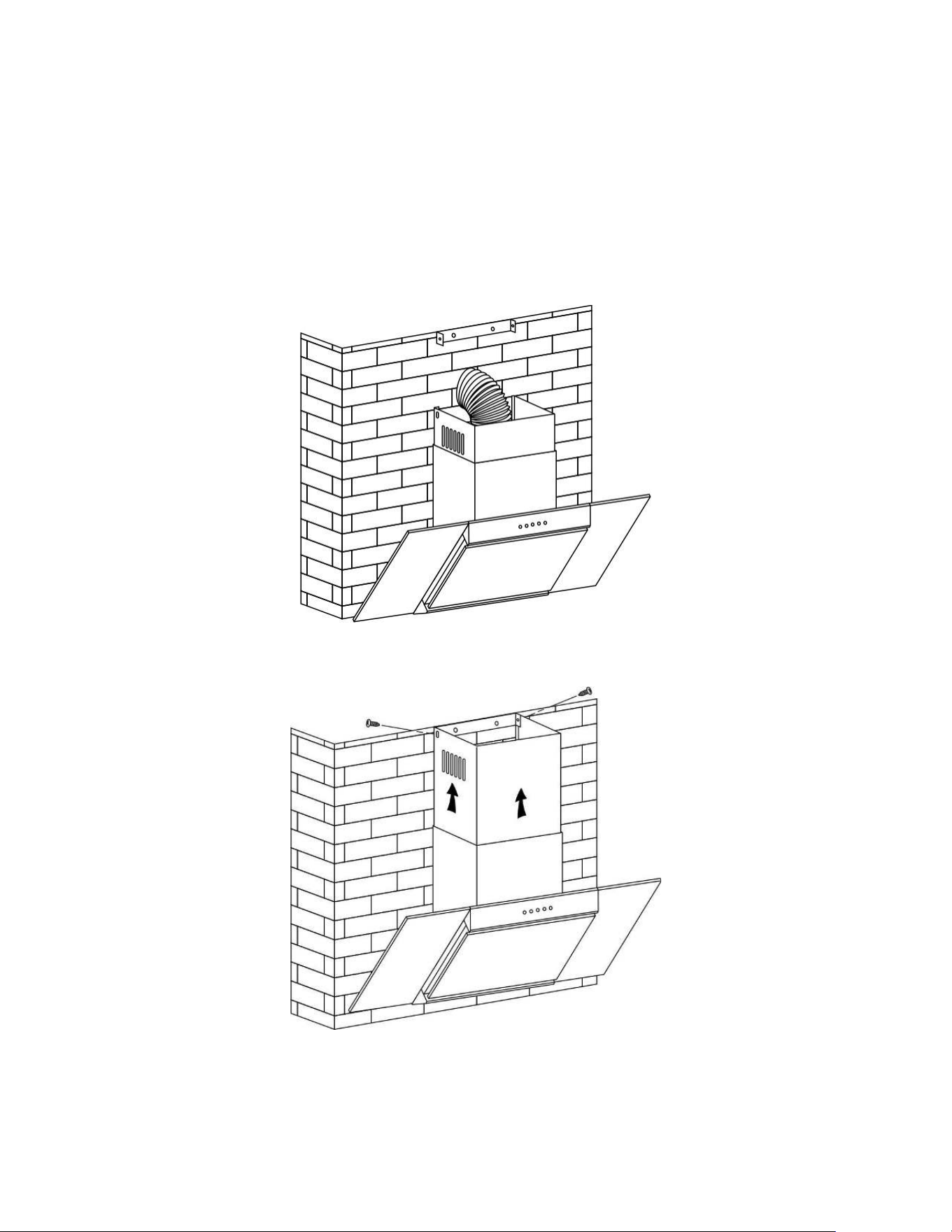
9. Drill 2 holes to accommodate plate II. Screw and tighten the plate II onto the
wall with the screws (4mm x 40 mm) and wall plugs provided.
Note: Plate II is used to fix the chimney. The below diagram is for reference.
Fixing the chimney to wall plate is done at the end of installation.
12
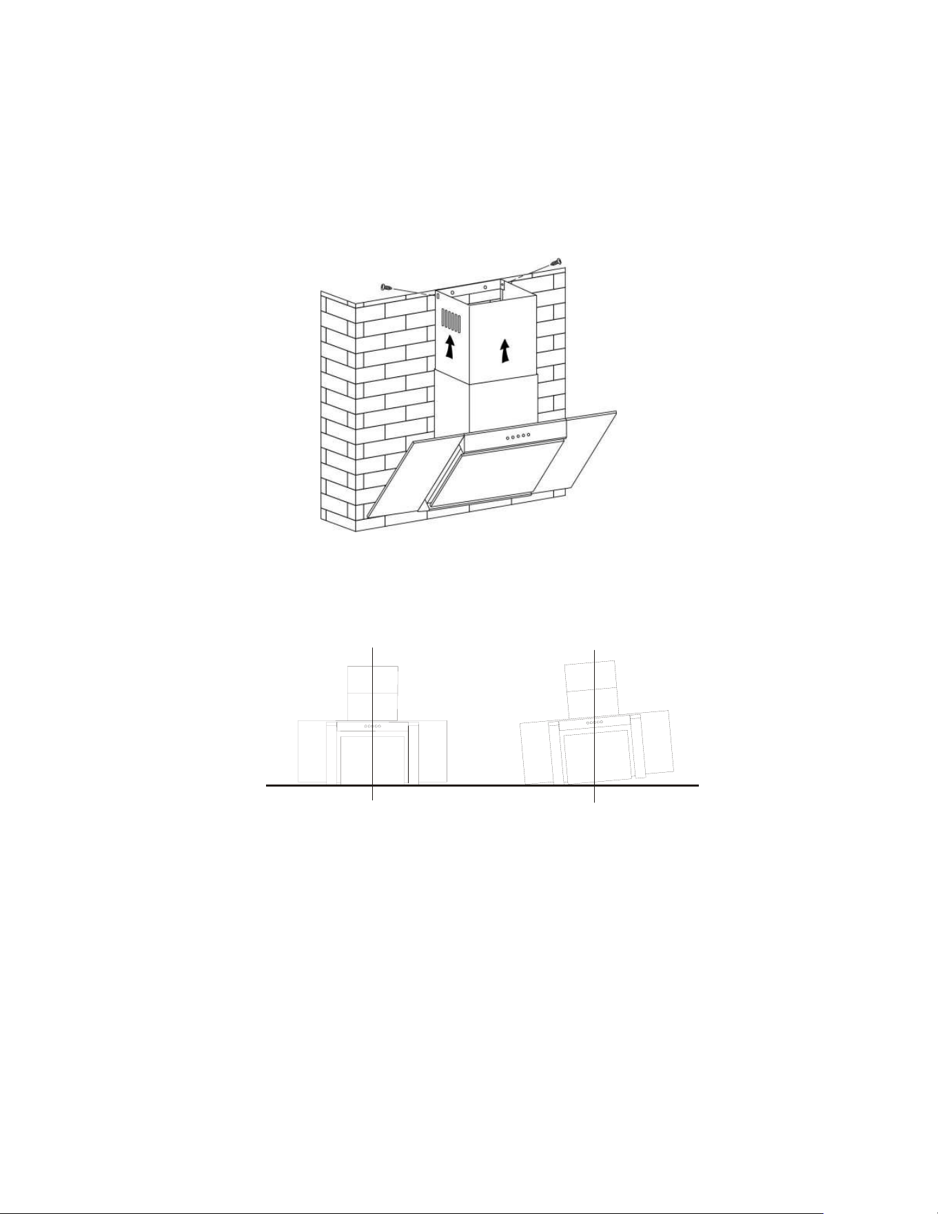
10. Put the installed chimneys on the cooker hood. Fix the Plate I to the wall by
using 2 (4mm x 40 mm) screws and wall plugs. Pull out extensible pipe till it
feeds through the hole on the wall.
Lift the inner chimney onto the plate II, fix the inner chimney to the plate II by
using 2 screws (4mm x 8mm).
After installation, make sure that the extractor is level to avoid grease collection
at one end.
√ X
11. Before usage, read all the instructions and make sure that the voltage (V)
and the frequency (Hz) indicated on the identification plate (found inside the
cooker hood) and all the data inside the appliance are exactly the same as
the voltage and frequency in your home. Then plug the power lead into the
power socket (unless you are hard-wiring in to the mains) and start the cooker
hood. .
13
CARBON FILTER
(OPTIONAL)
Activated carbon filters should be used to trap odours (optional – available from
the same stockist you purchased the hood from) and must be used if the hood is
not vented to the outside.
reference:
eiQCF110 (Carbon Filter Pack of 2 – fits both 60cm and 90cm models)
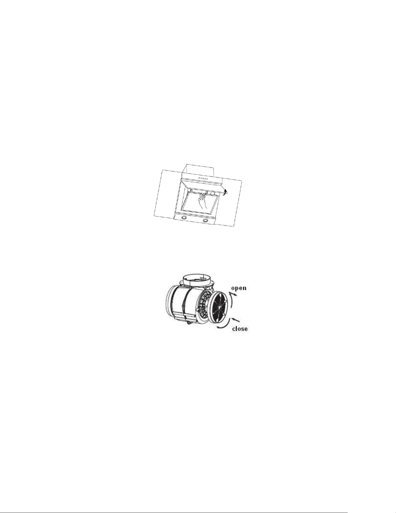
In order to install the activated carbon filters, the aluminium filter should be
removed first. Press the lock and pull it downward as below:
Put the activated carbon filter onto the end of the motor unit and turn it in anti-
clockwise direction. Repeat the same on the other side (see below)
NOTE:
• Make sure the filter is securely locked. Otherwise, it could loosen and
cause damage to unit.
• When the activated carbon filters are attached, the suction power will be
lowered.
• The charcoal filter cannot be washed or recycled. It should be changed at
three or six months according to the amount of use the hood receives.
Replacements are available from the stockist from whom you purchased the
hood:
eiQCF110 (Carbon Filter Pack of 2 – fits both 60cm and 90cm models)
14
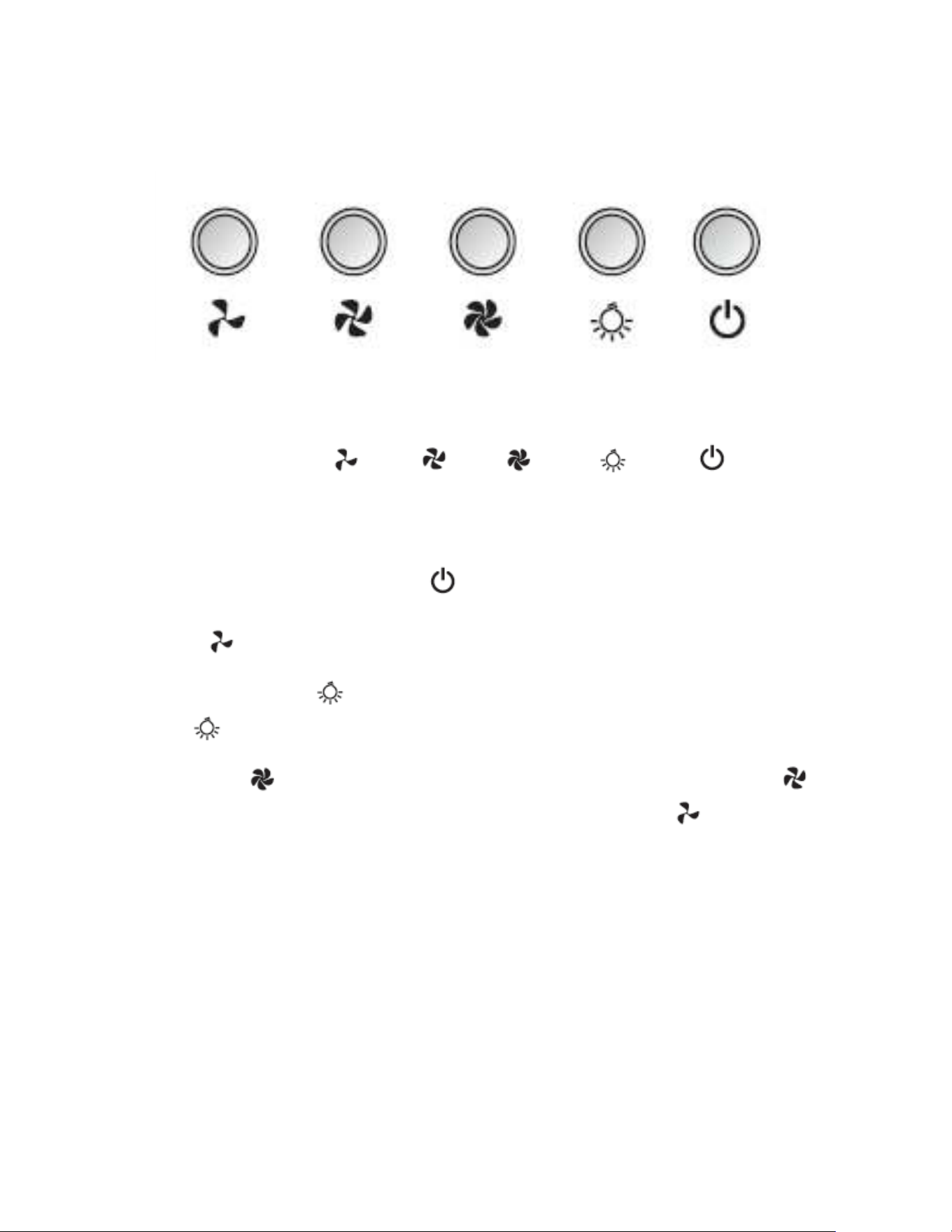
OPERATION
There are five buttons: (Low), (Mid), (High), (Light), (Power).
1. After connecting the hood, the indicator light will turn on and the hood will enter
standby mode.
2. Power on: Press power button once, and the power indicator light will be
turn on, the hood will automatically begin at low speed. The low speed indicator
light will be on. Press the power button again to turn the unit off.
3. Press lamp button once; lights will be turned on. The lamp indicator will turn
off . Press the light button again to turn off the light.
4. Press the (High) button to turn on the high-speed function. Press the
(Mid) button once, motor runs on middle speed. Press the (low) button
once, motor runs on low speed. The corresponding speed indicator will be lit
while in use.

15
MAINTENANCE
Before cleaning, switch the unit off and pull out the plug, or switch off at the
relevant mains switch if the unit has been hard-wired in. Make sure the unit has
no power being fed to it.
I. Regular Cleaning
Use a soft cloth moistened with hand-warm mildly soapy water or household
cleaning detergent. Never use metal pads, chemical, abrasive material or a stiff
brush to clean the unit. Do not use a steam-cleaner to clean the hood; electrical
components could be damaged or short-circuit as a result.
II. Monthly Cleaning for metallic anti-grease filter
Clean the filter every month; an excessive build-up of grease can become a fire
hazard. The filter collects grease, smoke and dust, so the filter directly affects the
efficiency of the cooker hood. If it’s not cleaned, the grease residue (potentially
flammable) will saturate on the filter.
Remove the filter as shown in the Installation section. Clean it with a soft nylon
brush in a mild solution of warm water and a small amount of washing up liquid.
Washing up liquid alone should not be used. After cleaning, allow the filter to
drain and then dry thoroughly.
Replacement grease filters are available from the same stockist from where you
purchased the hood:
60cm models: eiQAL52C160 x 1
90cm models: eiQAL52C190 x 1
III. Replacement for Activated Carbon Filter
These are only required in units that have been installed in recirculation mode
(not vented to the outside). These filters trap odours and must be replaced at
ideally every 3-6 months depending on how frequently the cooker hood has been
used.
eiQCF110 (Carbon Filter Pack of 2 – fits both 60cm and 90cm models)
16
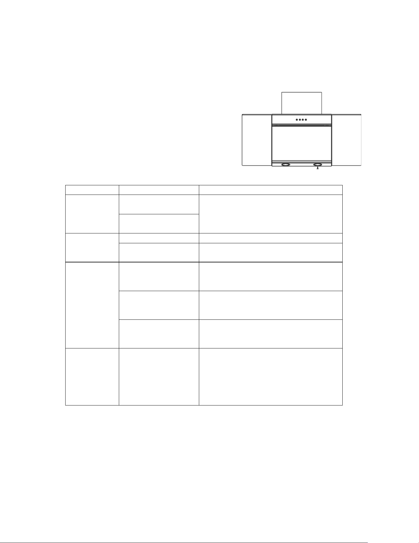
LIGHT REPLACEMENT
IMPORTANT: The light fitting must be replaced by the manufacturer, its service
agent or similarly qualified persons
LED lamp:
1. Use the correct light: 2 x 1.5W LED.
2. Carefully take out the lamp with a suitable
tool.
3. Change the lamp.
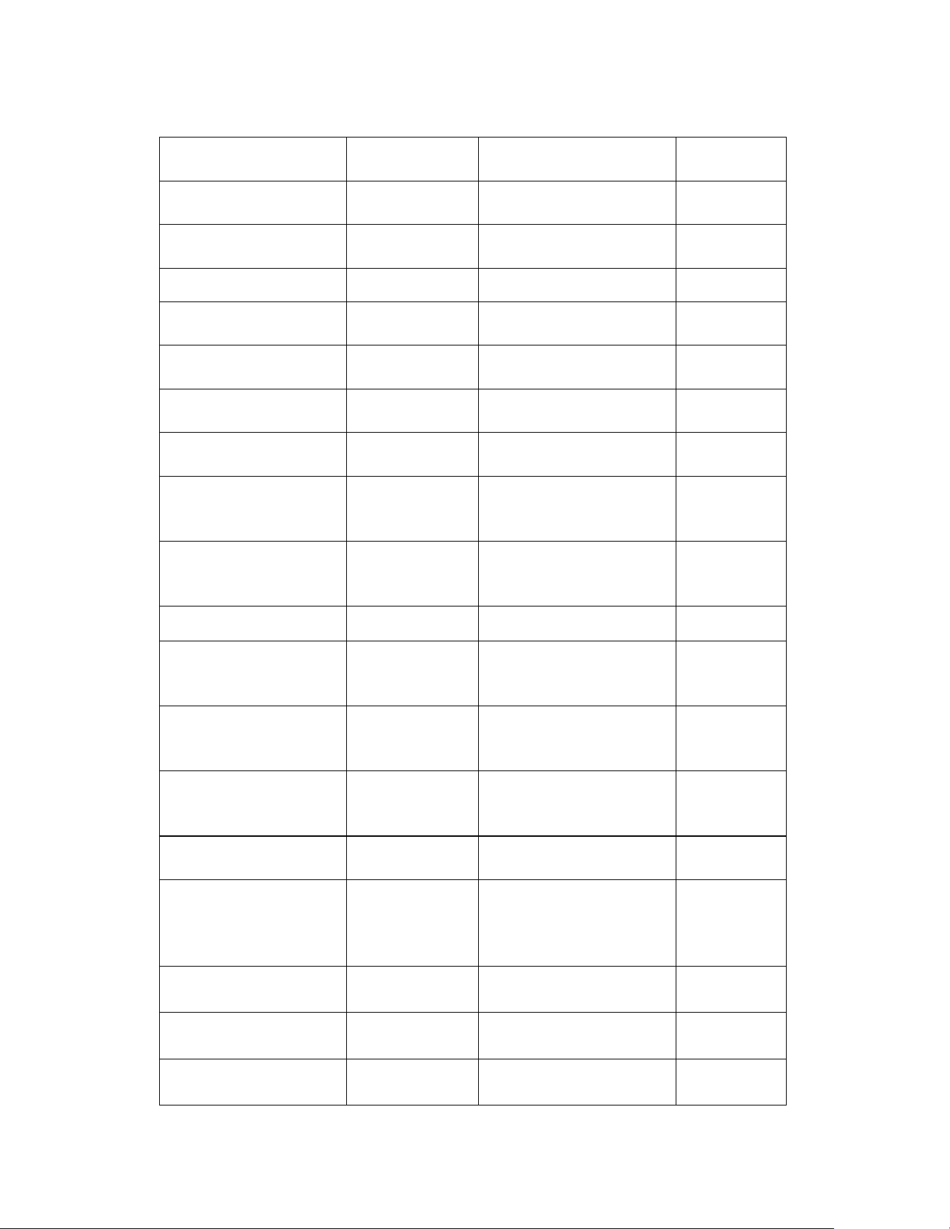
TROUBLESHOOTING
Fault
Cause
Solution
Light on, but
fan does not
work
The fan blade is
jammed.
Switch off the unit. Repair to be
carried out by qualified service
personnel only.
The motor is
damaged.
Both light
and fan do
not work
Light blown
Replace the light with correct rating.
Power cord loose
Plug in to the power supply again.
Excessive
Vibration
The fan blade is
damaged.
Switch off the unit. Repair to be
carried out by qualified service
personnel only.
The fan motor is
not fixed tightly.
Switch off the unit. Repair to be
carried out by qualified service
personnel only.
The unit is not hung
properly on the
bracket.
Take down the unit and check
whether the bracket is in proper
location.
Suction
performance
not good
1 Grease filters
clogged
2 Distance between
the unit and the
cooking plane too
great.
1 Clean or replace grease filters.
2. Readjust the distance to between
70cm and 80cm.
17
PRODUCT FICHE
Symbol
Value
Unit
Model identification
eiQCHFGBSS60
eiQCHFGBSS90
Annual Energy
Consumption
AEC
hood
81.6
kWh/a
Time increase factor
f
1.4
Fluid Dynamic
Efficiency
FDE
hood
15.9
Fluid Dynamic
Efficiency class
Class D
Energy Efficiency
Index
EEI
hood
80.0
Energy Efficiency
class
Class C
Measured airflow
rate at the best
efficiency
Q
BEP
274.8
m
3
/h
Measured air
pressure at best
efficiency point
P
BEP
318
Pa
Maximum airflow
Q
max
581.8
m
3
/h
Air flow at working
point (highest
setting)
553.9
m
3
/h
Air flow at working
point (lowest
setting)
398.8
m
3
/h
Measured electric
power input at best
efficiency point
W
BEP
152.6
W
Nominal power of
the lighting system
W
L
4.1
W
Average illumination
of the lighting
system on the
cooking surface
E
middle
82(600MM);
76(900MM);
lux
Lighting efficiency
LE
hood
20.0(600MM);
18.5(900MM);
lux/W
Lighting efficiency
class
Class C
Grease Filtering
Efficiency
GFE
hood
64.7
18
Grease Filtering
Efficiency (GFE
hood) class
Class E
Measured power
consumption on
standby mode
P
S
0.53-
W
Measured power
consumption on off
mode
P
O
0.38
W
Sound power level
(Highest setting)
L
WA
69
dB
Sound power level
(Lowest setting)
L
WA
65
dB
The following shows how to reduce total environmental impact (e.g. energy use)
of the cooking process).
(1) Install the cooker hood in a proper place where there is efficient
ventilation.
(2) Clean the cooker hood regularly so as not to block the airway.
(3) Remember to switch off the cooker hood light after cooking.
(4) Remember to switch off the cooker hood after cooking.
19
INFORMATION FOR DISMANTLING
Do not dismantle the appliance in a way which is not shown in the user manual. The
appliance could not be dismantled by user. At the end of life, the appliance should not be
disposed of with household waste. Check with you Local Authority or retainer for recycling
advice.
electriQ UK SUPPORT
www.electriQ.co.uk/support
Call: 03303903061
Office hours: 9AM - 5PM Monday to Friday
www.electriQ.co.uk
Unit J6, Lowfields Business Park
Lowfields Way, Elland
West Yorkshire, HX5 9DA
Recycling facilities are now available for all customers at which you can
deposit your old electrical products. Customers will be able to
take any old electrical equipment to participating sites run by
their local councils. Please remember that this equipment will
be further handled during the recycling process, so please be
considerate when depositing your equipment. Please contact
the local council for details of your local household waste
recycling centres.