COLD DRAFT
®
INSTALLATION & OPERATING GUIDE
Designs, materials, weights, specifications, and dimensions for equipment
or replacement parts are subject to change without notice.
54261.0003 J 01/20 © 2017 Bunn-O-Matic Corporation
Bunn-O-Matic Corporation
Post Office Box 3227, Springfield, Illinois 62708-3227
Phone (217) 529-6601 | Fax (217) 529-6644
www.bunn.com

2
082218
BUNN-O-MATIC COMMERCIAL PRODUCT WARRANTY
Bunn-O-Matic Corp. (“BUNN”) warrants equipment manufactured by it as follows:
1) Airpots, thermal carafes, decanters, GPR servers, iced tea/coffee dispensers, MCR/MCP/MCA single cup brewers,
thermal servers and ThermoFresh
®
servers (mechanical and digital) 1 year parts and 1 year labor.
2) All other equipment - 2 years parts and 1 year labor plus added warranties as specified below:
a) Electronic circuit and/or control boards - parts and labor for 3 years.
b) Compressors on refrigeration equipment - 5 years parts and 1 year labor.
c) Grinding burrs on coffee grinding equipment to grind coffee to meet original factory screen sieve analysis -
parts and labor for 4 years or 40,000 pounds of coffee, whichever comes first.
These warranty periods run from the date of installation BUNN warrants that the equipment manufactured by it will be
commercially free of defects in material and workmanship existing at the time of manufacture and appearing within the
applicable warranty period. This warranty does not apply to any equipment, component or part that was not manufactured
by BUNN or that, in BUNN’s judgment, has been affected by misuse, neglect, alteration, improper installation or operation,
improper maintenance or repair, non periodic cleaning and descaling, equipment failures related to poor water quality,
damage or casualty. In addition, the warranty does not apply to replacement of items subject to normal use including but
not limited to user replaceable parts such as seals and gaskets. This warranty is conditioned on the Buyer 1) giving BUNN
prompt notice of any claim to be made under this warranty by telephone at (217) 529-6601 or by writing to Post Office Box
3227, Springfield, Illinois 62708-3227; 2) if requested by BUNN, shipping the defective equipment prepaid to an authorized
BUNN service location; and 3) receiving prior authorization from BUNN that the defective equipment is under warranty.
THE FOREGOING WARRANTY IS EXCLUSIVE AND IS IN LIEU OF ANY OTHER WARRANTY, WRITTEN OR ORAL, EX-
PRESS OR IMPLIED, INCLUDING, BUT NOT LIMITED TO, ANY IMPLIED WARRANTY OF EITHER MERCHANTABILITY OR
FITNESS FOR A PARTICULAR PURPOSE. The agents, dealers or employees of BUNN are not authorized to make modi-
fications to this warranty or to make additional warranties that are binding on BUNN. Accordingly, statements by such
individuals, whether oral or written, do not constitute warranties and should not be relied upon.
If BUNN determines in its sole discretion that the equipment does not conform to the warranty, BUNN, at its exclusive op-
tion while the equipment is under warranty, shall either 1) provide at no charge replacement parts and/or labor (during the
applicable parts and labor warranty periods specified above) to repair the defective components, provided that this repair
is done by a BUNN Authorized Service Representative; or 2) shall replace the equipment or refund the purchase price for
the equipment.
THE BUYER’S REMEDY AGAINST BUNN FOR THE BREACH OF ANY OBLIGATION ARISING OUT OF THE SALE OF THIS
EQUIPMENT, WHETHER DERIVED FROM WARRANTY OR OTHERWISE, SHALL BE LIMITED, AT BUNN’S SOLE OPTION
AS SPECIFIED HEREIN, TO REPAIR, REPLACEMENT OR REFUND.
In no event shall BUNN be liable for any other damage or loss, including, but not limited to, lost profits, lost sales, loss of
use of equipment, claims of Buyer’s customers, cost of capital, cost of down time, cost of substitute equipment, facilities
or services, or any other special, incidental or consequential damages.
392, A Partner You Can Count On, Air Infusion, AutoPOD, AXIOM, BrewLOGIC, BrewMETER, Brew Better Not Bitter, Brew-
WISE, BrewWIZARD, BUNN Espress, BUNN Family Gourmet, BUNN Gourmet, BUNN Pour-O-Matic, BUNN, BUNN with
the stylized red line, BUNNlink, Bunn-OMatic, Bunn-O-Matic, BUNNserve, BUNNSERVE with the stylized wrench design,
Cool Froth, DBC, Dr. Brew stylized Dr. design, Dual, Easy Pour, EasyClear, EasyGard, FlavorGard, Gourmet Ice, Gourmet
Juice, High Intensity, iMIX, Infusion Series, Intellisteam, My Café, Phase Brew, PowerLogic, Quality Beverage Equipment
Worldwide, Respect Earth, Respect Earth with the stylized leaf and coffee cherry design, Safety-Fresh, savemycoffee.com,
Scale-Pro, Silver Series, Single, Smart Funnel, Smart Hopper, SmartWAVE, Soft Heat, SplashGard, The Mark of Quality in
Beverage Equipment Worldwide, ThermoFresh, Titan, trifecta, TRIFECTA (sylized logo), Velocity Brew, Air Brew, Beverage
Bar Creator, Beverage Profit Calculator, Brew better, not bitter., Build-A-Drink, BUNNSource, Coffee At Its Best, Cyclonic
Heating System, Daypart, Digital Brewer Control, Element, Milk Texturing Fusion, Nothing Brews Like a BUNN, Picture
Prompted Cleaning, Pouring Profits, Signature Series, Sure Tamp, Tea At Its Best, The Horizontal Red Line, Ultra are either
trademarks or registered trademarks of Bunn-O-Matic Corporation. The commercial trifecta
®
brewer housing configura-
tion is a trademark of Bunn-O-Matic Corporation.

3
Warranty ............................................................................................................................2
User Notices ......................................................................................................................4
North American Requirements ...........................................................................................5
Plumbing Requirements ....................................................................................................6
Initial Set-Up ...................................................................................................................... 6
Nitrogen Gas Hook Up .......................................................................................................6
Electrical Requirements .....................................................................................................7
Product Concentrate Requirements ...................................................................................7
Plumbing Hookup ..............................................................................................................7
Initial Fill ............................................................................................................................8
Set Up Instructions ............................................................................................................9
Door Cover Installation ....................................................................................................10
Operating Controls ........................................................................................................... 11
Cleaning & Sanitizing Product Containers or BIB Connectors ..........................................13
Preventive Maintenance ...................................................................................................16
Loading & Priming Containers or Bag-In-Box with SCHOLLE/ASTRA Connectors ..........17
Adjustments & Optional Settings .....................................................................................21
Nitron
2
Cold Draft Decommission Procedure ...................................................................24
Fault Codes ......................................................................................................................26
Coolant Diagram ..............................................................................................................27
Schematic Wiring Diagram ..............................................................................................28
082218
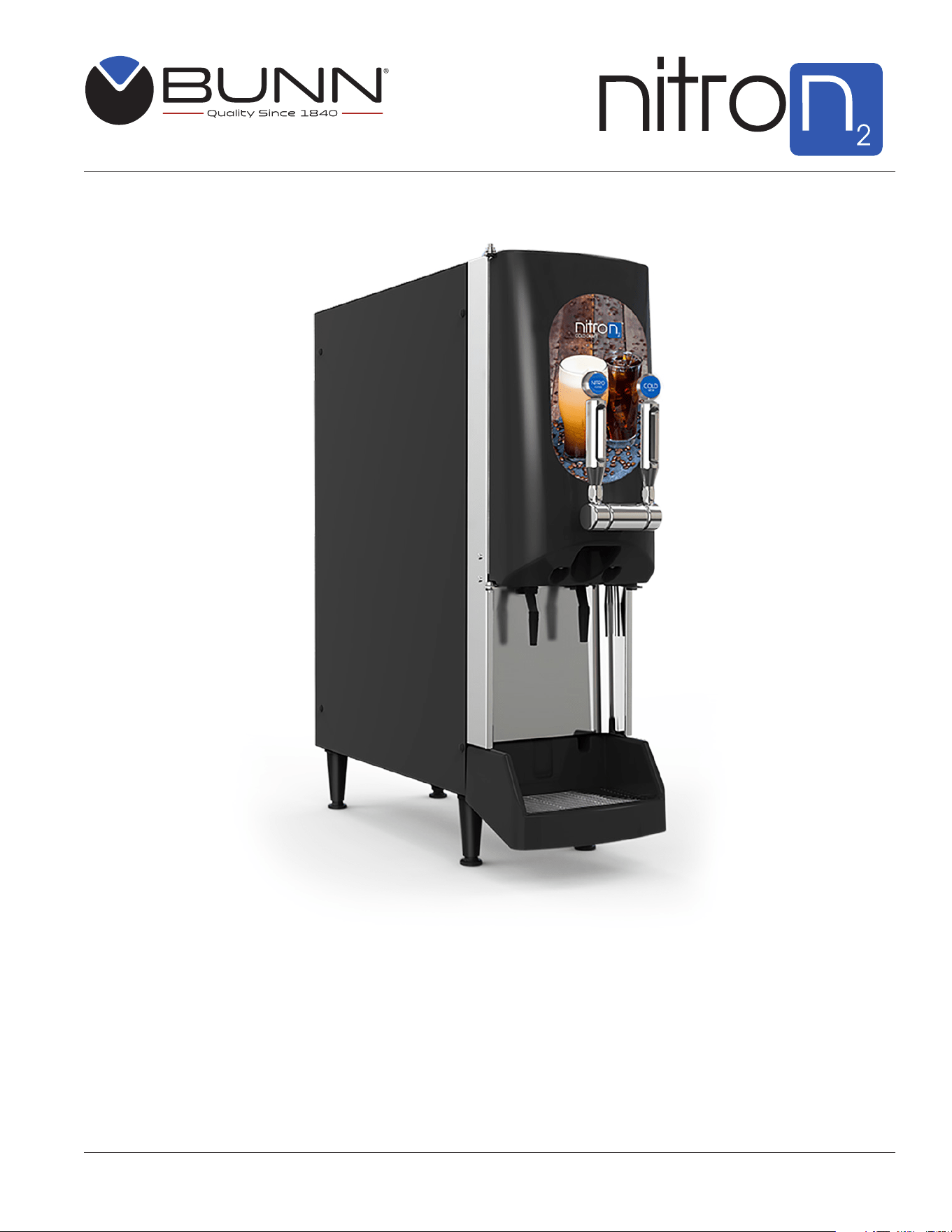
INTRODUCTION
The cold draft dispenser and door have been shipped in one complete package (the door is in its own package
inside the larger box). To prevent damage, the door should remain in its individual packaging until it is ready
for installation. This package also includes the drip tray and grate, and the tapper handles for mounting onto
the door of the dispenser.
CONTENTS
4
Carefully read and follow all notices on the equipment and in this manual. They were written for your protection.
All notices are to be kept in good condition. Replace any unreadable or damaged labels.
00656.0001
As directed in the International Plumbing Code of the
International Code Council and the Food Code
Manual of the Food and Drug Administration (FDA),
this equipment must be installed with adequate
backflow prevention to comply with federal, state
and local codes. For models installed outside the
U.S.A., you must comply with the applicable Plumb-
ing /Sanitation Code for your area.
00986.0002
WARNING
FAILURE TO COMPLY RISKS EQUIPMENT
DAMAGE, FIRE OR SHOCK HAZARD.
READ THE ENTIRE OPERATING MANUAL
BEFORE USING THIS PRODUCT
Use only on a properly protected circuit
capable of the rated load.
Electrically ground the chassis.
Follow national/local electrical codes.
Do not use near combustibles.
Do not deform plug or cord.
27442.0000
Moving Parts.
Do not operate
unit with this
panel removed.
Risk Of Electrical Shock.
Disconnect power before
servicing unit.
WARNING
33461.0001
CHARGE
Type R134A, Amount 9 oz (255 gm)
Design Pressures:
High 255 psi (17.6 bar) (1.76 MPa)
Low 36 psi (2.5 bar) (0.25 MPa)
41509.0006
SET N2 PRESSURE
125 PSIG
USER NOTICES
082218

5
CE REQUIREMENTS
• This appliance must be installed in locations where it can be overseen by trained personnel.
• For proper operation, this appliance must be installed where the temperature is between 5°C to 35°C.
• Appliance shall not be tilted more than 10° for safe operation.
• An electrician must provide electrical service as specified in conformance with all local and national codes.
• This appliance must not be cleaned by water jet.
• This appliance can be used by persons aged from 18 years and above if they have been given supervision or
instruction concerning use of the appliance in a safe way and if they understand the hazards involved.
• Keep the appliance and its cord out of reach of children aged less than 18 years.
• Appliances can be used by persons 18 years and above with reduced physical, sensory or mental capabilities
or lack of experience and knowledge if they have been given supervision or instruction concerning use of the
appliance in a safe way and understand the hazards involved.
• Children under the age of 18 years should be supervised to ensure they do not play with the appliance.
• If the power cord is ever damaged, it must be replaced by the manufacturer or authorized service personnel
with a special cord available from the manufacturer or its authorized service personnel in order to avoid a hazard.
• Machine must not be immersed for cleaning.
• Cleaning and user maintenance shall not be made by children unless they are older than 18 years and supervised.
• This appliance is intended to be used in household and similar applications such as:
– staff kitchen areas in shops, offices and other working environments;
– by clients in hotels, motels and other residential type environments;
– bed and breakfast type environments.
• This appliance not intended to be used in applications such as:
– farm houses;
• Access to the service areas permitted by Authorized Service personnel only.
• The A-Weighted sound pressure level is below 70 dBA.
NORTH AMERICAN REQUIREMENTS
• This appliance must be installed in locations where it can be overseen by trained personnel.
• For proper operation, this appliance must be installed where the temperature is between 41°F to 90°F
(5°C to 32°C) and 50% humidity.
• Appliance shall not be tilted more than 10° for safe operation.
• An electrician must provide electrical service as specified in conformance with all local and national codes.
• This appliance must not be cleaned by pressure washer.
• This appliance can be used by persons aged from 18 years and above if they have been given supervision or
instruction concerning use of the appliance in a safe way and if they understand the hazards involved.
• Keep the appliance and its cord out of reach of children aged less than 18 years.
• Appliances can be used by persons 18 years and above with reduced physical, sensory or mental capabilities or lack
of experience and knowledge if they have been given supervision or instruction concerning use of the appliance in a
safe way and understand the hazards involved.
• Children under the age of 18 years should be supervised to ensure they do not play with the appliance.
• If the power cord is ever damaged, it must be replaced by the manufacturer or authorized service personnel with a
special cord available from the manufacturer or its authorized service personnel in order to avoid
a hazard.
• Machine must not be immersed for cleaning.
• Cleaning and user maintenance shall not be made by children unless they are older than 18 years and supervised.
• This appliance is intended for commercial use in applications such as:
– staff kitchen areas in shops, offices and other working environments;
– by clients in hotel and motel lobbies and other similar types of environments;
• Access to the service areas permitted by Authorized Service personnel only.
082218

6
PLUMBING REQUIREMENTS
This dispenser must be connected to a FILTERED WATER source with operating pressure between 30 and 90 psi
(0.207 and 0.621 mPa) dynamic. This water source must be capable of producing a minimum flow rate of 2 fluid
ounces (88.7 milliliters) per second. A shut off valve should be installed in the line that will supply the dispenser.
If installing a water filter, it should be installed as close as possible to the inlet of the machine, but downstream
of the shut-off valve. The machine is supplied with a 3/8” (9.52 mm) male barb fitting.
NOTE: At least 18 inches (457 mm) of an FDA approved flexible beverage tubing, such as reinforced braided
polyethylene, before the dispenser will facilitate movement to clean the counter top. BUNN-O-MATIC does
not recommend the use of saddle valves to install the dispenser. The size and shape of the hole(s) made in
the supply line(s) by saddle valves may restrict water flow.
If the water pressure is below 30 psi (dynamic) pressure, a booster pump (P/N 41815.1000) is required at the
water line. When installing a water filter and a booster pump, install the water filter in between the booster pump
and the machine.
The cold draft dispenser dimensions are 10"W x 28.4"D x 34"H. The dispenser is designed for indoor use only,
in ambient temperatures ranging from 50°F to 90°F and 65% relative humidity environments. Avoid locating the
machine where it will be subject to direct sunlight or exposed to other external heat sources. Install the dispenser
on a counter that is able to support 150lbs (68 KG) of weight from the machine. Allow a minimum clearance of 6”
at the back and top of the dispenser for proper air circulation. Leave some space so the dispenser can be moved
for cleaning. For optimum performance, do not let warm air from surrounding machines blow on the dispenser.
As directed in the International Plumbing Code of the International Code Council and the Food Code Manual of
the Food and Drug Administration (FDA), this equipment must be installed with adequate back flow prevention to
comply with federal, state and local codes. For models installed outside the U.S.A., you must comply with the
applicable Plumbing /Sanitation Code for your area.
NITROGEN GAS HOOK-UP
An N
2
high-pressure tank must also be available prior to installation (customer supplied). There must be
sufficient space for the cylinder and should be properly secured with a stand or chain to comply with local
safety codes.
The cold draft dispenser will need to be connected to an external Nitrogen (N
2
) source. This will require an N
2
pressure regulator to be installed at the tank with a gas supply line to the dispenser. The external N
2
supply
connection is a ¼” MFL located on the back of the machine.
The cold draft dispenser may also need connected to a nitrogen generator. The supply pressure from the
generator to the machine should be set to 125 psi.
NOTE: If the customer is supplying their own regulator, the regulator should have a working pressure up to
130 psi. 6-feet of dedicated N
2
gas tubing line is required to connect the N
2
regulator to the machine. The
gas tubing line must be rated at least 130 psi and requires a ¼” FFL fitting at the end of the line to connect
to the machine.
NOTE: For best drink consistency and nitrogen infusion, the nitrogen supply pressure to the machine
should be set to 125 psi and maintain +/-10 psi from the 125 psi pressure set point.
NOTE: To ensure safe N
2
operation and compliance with local safety codes, the N
2
cylinder must be
properly secured. A strap or chain should be used as a means of properly securing the cylinder.
NOTE: When the supply nitrogen pressure drops below 100 psi, a red light indicator will flash at the top
of the dispenser door.
NOTE: This dispenser is not designed to accept CO
2
gas.
INITIAL SET-UP
082218
7
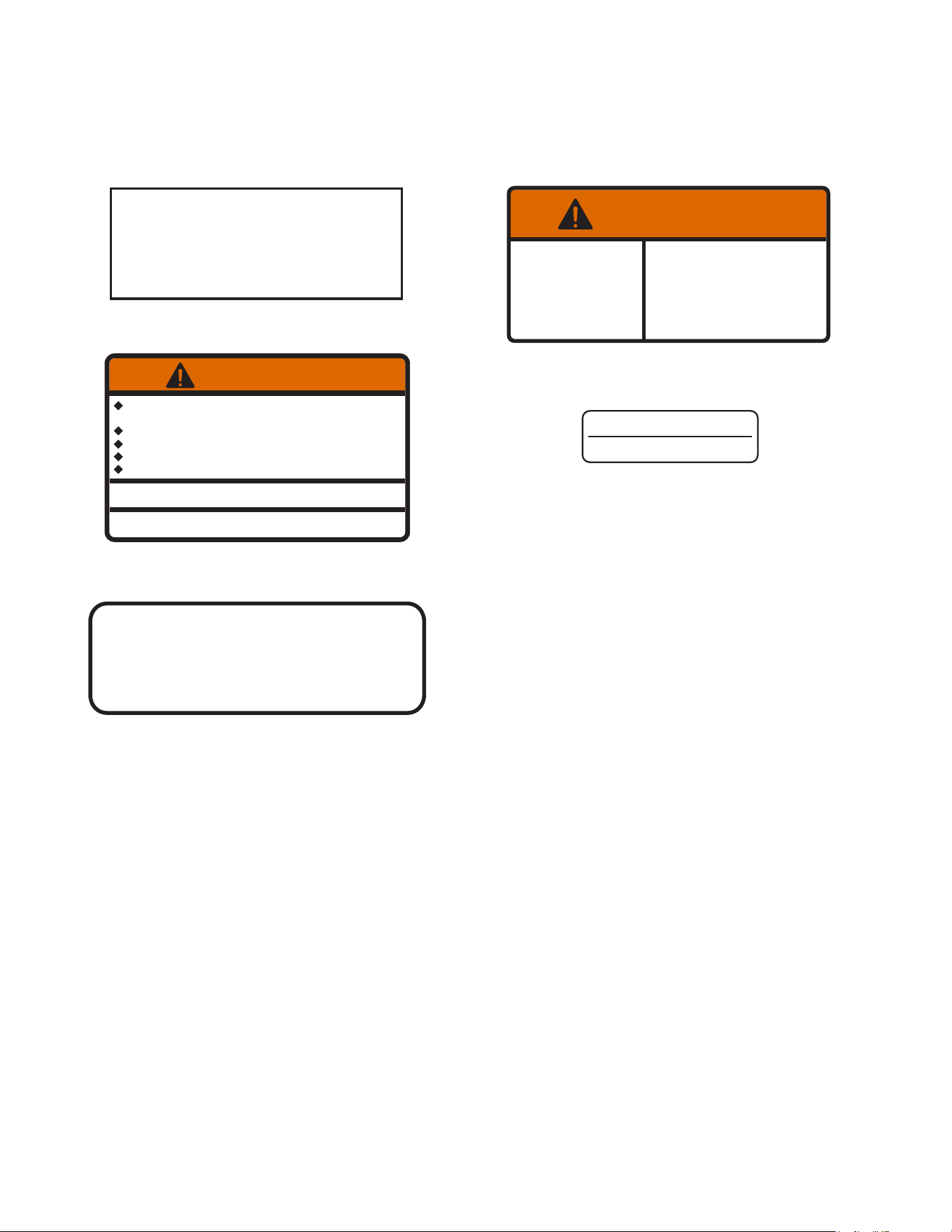
UK Plug
CAUTION: The dispenser must be disconnected from the power source until specified in Electrical Hook-Up.
The 120V rated dispensers have an attached cord set and require a 2-wire, grounded, individual branch circuit rated 120
volts ac, 15 amp, single phase, 60Hz. The receptacle must be within 6 feet of the machine. The mating connector is NEMA
5-15R. The 220-230V rated dispensers have an attached cord set with 2-wire, grounded, rated 230VAC, 13 amp (UK) or
16 amp (Europe), single phase, 50/60Hz.
Refer to the data plate for exact electrical requirements.
PRODUCT CONCENTRATE REQUIREMENTS
The dispenser works with a range of concentrates. Some dispensers will dispense a range of 4:1 to 12:1.
Confirm you have the correct dispenser for the concentrate you plan to use.
NOTE: Some concentrates may have different ratio capacities in the dispenser.
There are different product concentrate BIBs available today with a ball-valve or Scholle fitting. Along with
the dispense range, make sure you have the correct Nitron2 model to connect your BIB concentrate in the
dispenser. If the product is packaged in jugs, we recommend you pour the concentrate into our refillable
ball-valve containers (P/N 39302.0000).
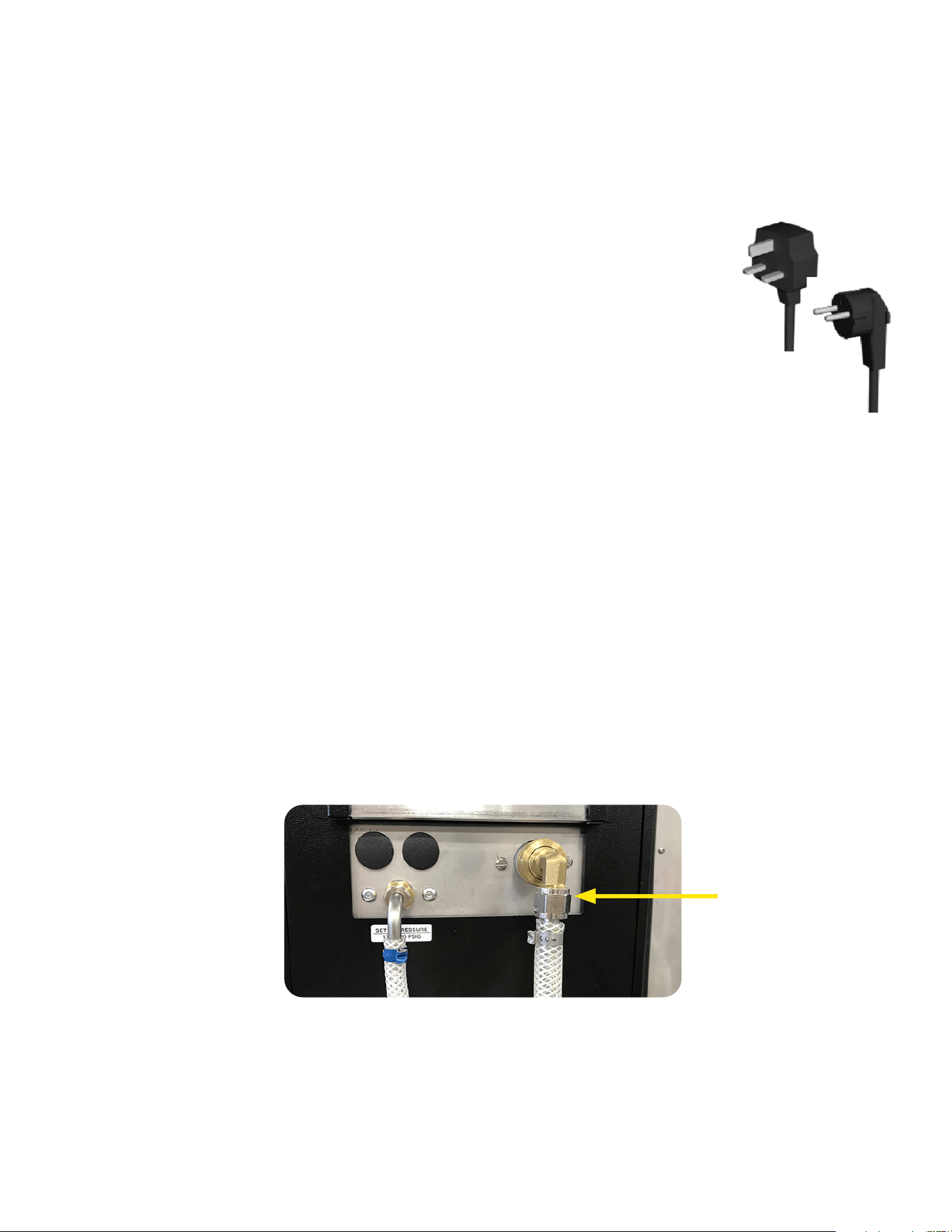
PLUMBING HOOKUP
The water connection is located on the rear of the dispenser. A 3/8" (9.52 mm) male flare adapter fitting is
supplied, installed on the rear of the dispenser.
NOTE: Water pipe connections and fixtures directly connected to a potable water supply shall be sized,
installed and maintained in accordance with federal, state and local codes.
CAUTION: Improper electrical installation will damage electronic components.
• An electrician must provide electrical service as specified.
• Using a voltmeter, check the voltage and color coding of each conductor at the electrical source.
Plug the dispenser into a 120V power source. Set the dispense switch to the ON position.
Water Hook Up
Euro Plug
ELECTRICAL HOOK-UP
CAUTION: Improper electrical installation will damage electronic components.
1. An electrician must provide electrical service as specified.
2. Using a voltmeter, check the voltage and color coding of each conductor at the electrical source.
3. Confirm that the refrigeration switch near the main control board is in the OFF position.
4. Connect the dispenser to the power source.
5. If plumbing is to be hooked up later, be sure the dispenser is disconnected from the power
source. If plumbing has been hooked up, the dispenser is ready for Initial Fill.
ELECTRICAL REQUIREMENTS
082218

8
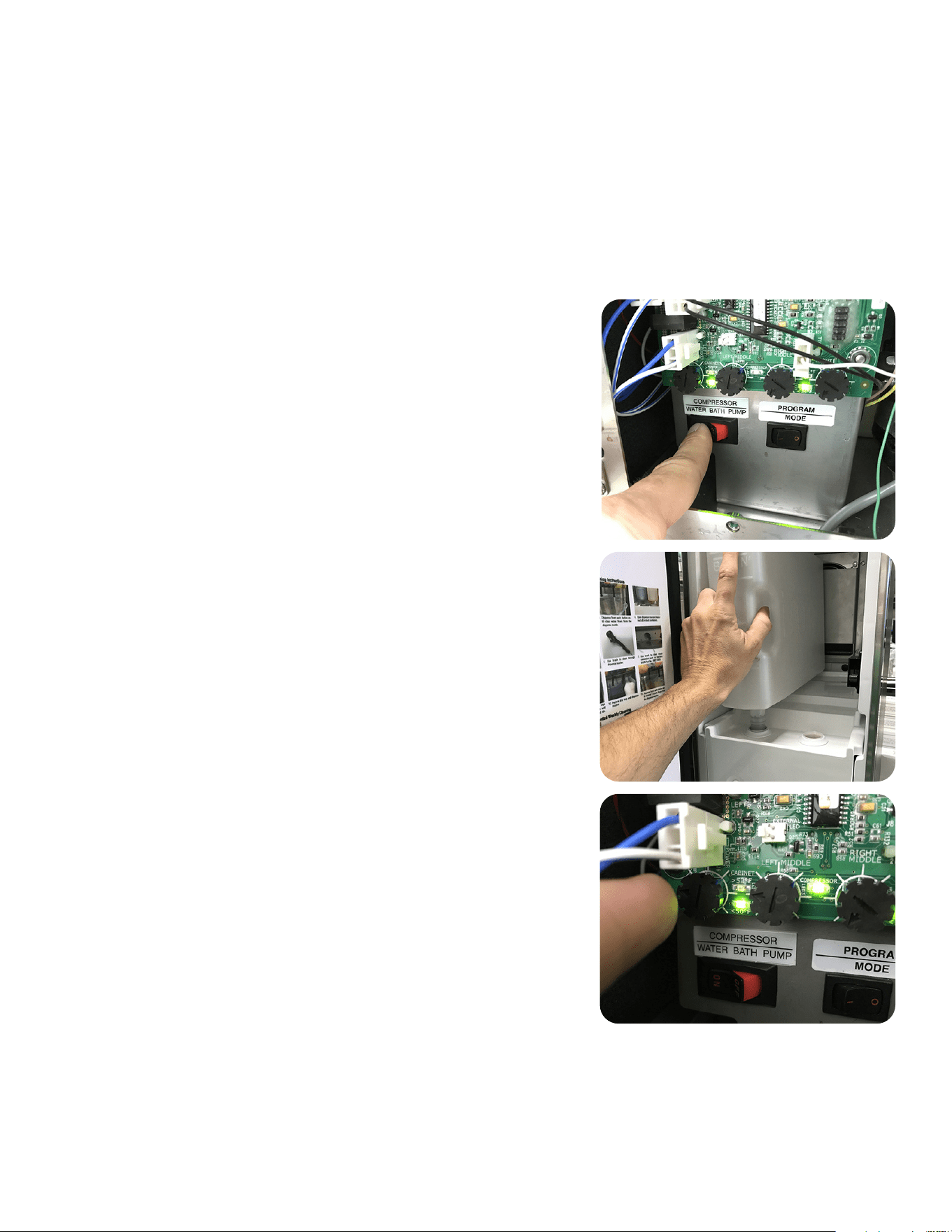
CAUTION: The dispenser must be disconnected from the power source throughout the initial fill except when
specified in the instructions.
1. Remove drip tray assembly and splash panel from the dispenser. Replace the drip tray.
2. Connect the water source to the back of the dispenser.
3. Connect dispenser to the power source.
4. The dispenser is equipped with an automatic bath fill circuit. When water is supplied and power is applied,
the water will automatically fill if program switch is OFF and dispense switch is ON.
5. It is okay to turn ON the compressor water bath switch as soon as the bath starts filling.
6. Replace the splash panel and drip tray.
7. It will take several hours to create the ice bank required for full dispenser performance. During this time, some
further trickling from the water bath is expected due to expansion caused by ice bank formation. While the
refrigeration system is creating the ice bank, the dispenser may be readied for use as described in Loading,
Priming and Adjustment.
INITIAL FILL
082218
9
1. After connecting to a filtered water source (see PLUMBING REQUIREMENTS), turn on the water supply to
the dispenser.
2. Connect the Nitrogen source to the dispenser, turn on the Nitrogen supply. For best drink consistency and
nitrogen infusion, the nitrogen supply pressure to the machine should be set to 125 psi and maintain +/-
10 psig from the 125 psi pressure set point. Verify that the regulator’s output gauge reads 125 psig. If the
regulator has a shut-off valve, move the regulator’s valve handle to the open position (the handle should
be parallel to the gas supply line).
3. Connect the LED lighting from the door cover to the door. Install the door using the 5 mounting screws
provided. (See DOOR COVER INSTALLATION)
4. Confirm that the dispense switch (located in upper right corner
of door when open) is in the OFF position.
5. Connect the switches from the handle set to the wire harness
on the door (note right and left connections). Install the handle
set using the two screws on the bottom side of the handles.
Snap the plug in the hole on the door under the handles.
6. Remove the drip tray and splash panel.
7. Install dispense nozzles and drip tray. The nozzle with the
Nitro Stout Insert goes in the LEFT* dispense station. The
nitro stout insert’s function is to provide back pressure while
dispensing Nitro Coffee and aides in creating the “cascading”
or surging effect in the dispensed drink.
8. Load product into both stations of the dispenser. For
SCHOLLE/ASTRA type BIB's, see Loading instructions for
those connectors. Prime each side with product by pulling the
tapper handle until you see finished product flowing from the
dispense nozzle.
9. Dispense a drink at each station and check the Brix by using
the Ratio Dispense Test or the Brix Dispense Test.
• The first dial (left-most potentiometer on the board) will
adjust pump speed for the LEFT dispense station. The
second dial (second from the left) will adjust pump speed
for the RIGHT dispense station. Best practice is to start
with the pump dial set to 9:00 position.
10. Make adjustments to pump speed to achieve the desired Brix
target of the product.
11. Reinstall the splash panel. The dispenser will take between 4-6
hours to completely build the ice bank.
NOTE: Some models dispense nitro beverage on both
dispense stations. For these models use a stout dispense
nozzle on both dispense stations.
SET-UP INSTRUCTIONS
082218
10
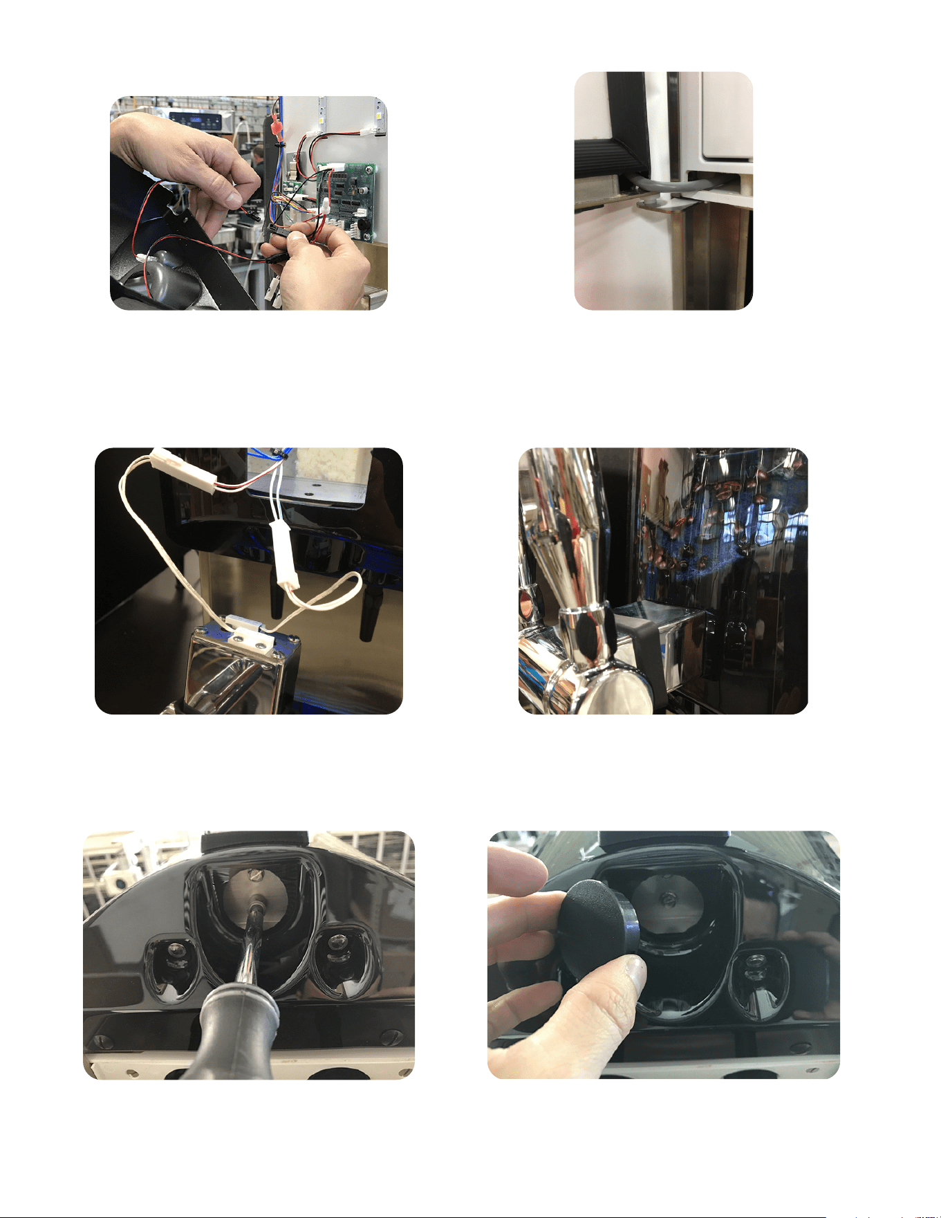
DOOR COVER INSTALLATION
2. Confirm door wiring harness is routed as shown
in photo when installing door cover. Install door
cover and secure the door cover using 5 screws
provided.
3. Connect tapper handle switches to harness in door.
NOTE: Connect left switch to blue wires (Left) and
right switch to red wires (Right).
5. Mount tapper handles through bottom of door as
shown using the screws provided.
6. Install black hole cover as shown.
4. Slide tapper handle into door assembly.
1. Install door cover by first plugging the LEDs
from the door into the black connectors with
RED/BLACK wires
082218
11
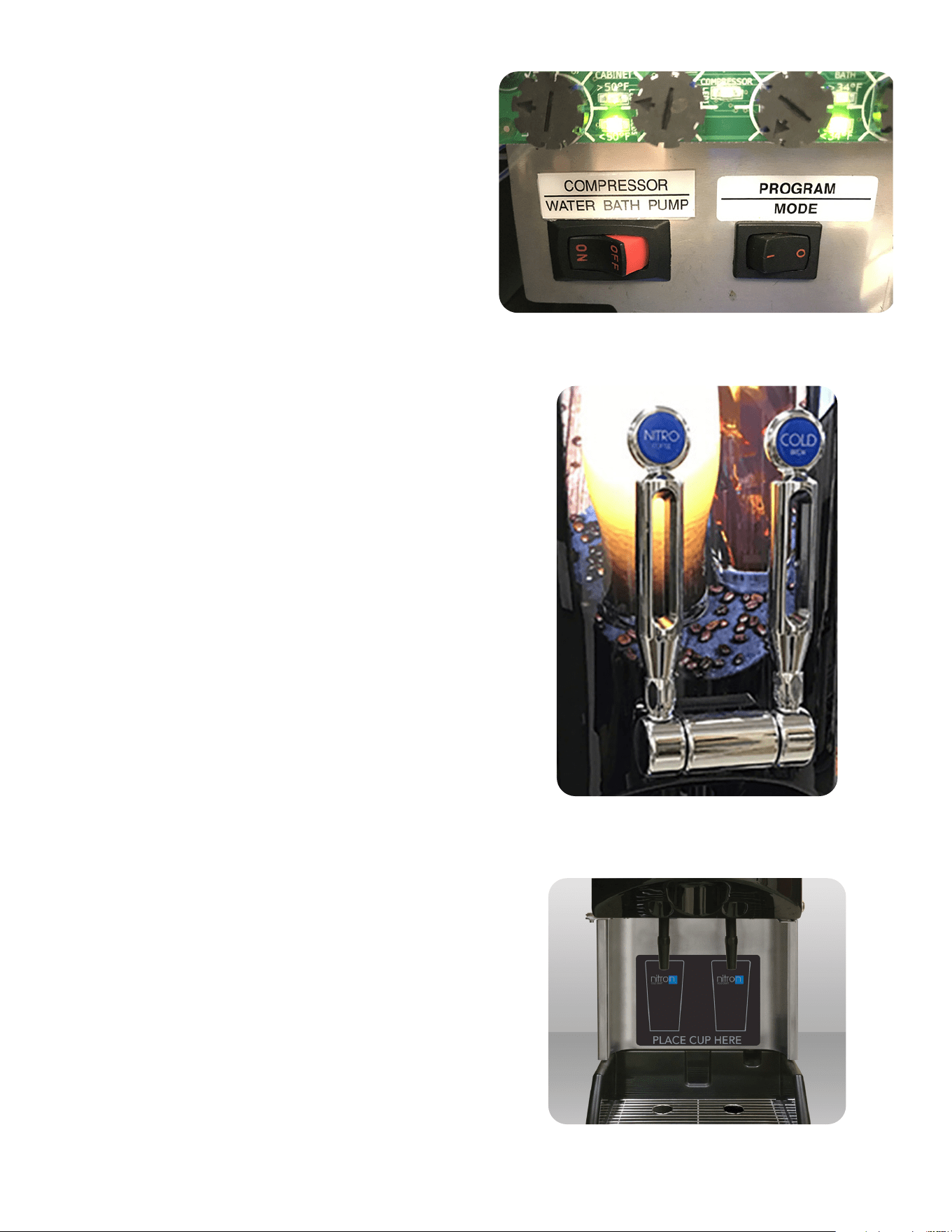
OPERATING CONTROLS
Refrigeration Switch
Product Dispense Handles
Compressor/Water Bath Switch
The refrigeration switch is located on the Electrical
Panel of the dispenser near the Circuit Board. This
switch controls power to the water bath pump and relay
contacts for the compressor and condenser fan motor.
Product Dispense Tap Handles
Pulling and holding tap handle will initiate product flow
from the respective nozzle; releasing the tap handle will
stop the flow.
082218
Cup Placement Decal
Cup Placement
The cup placement decal will assist users in proper cup
placement when dispensing a beverage. Apply the cup
placement decal to the splash panel as shown.
12
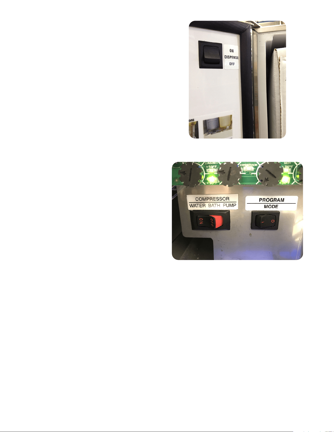
OPERATING CONTROLS (Cont.)
Dispense Lockout Switch
Dispense Lockout Switch
This switch is located inside the door at the top. It is
used to turn ON and OFF the Dispensing function. It is
also used for fill procedures.
Program Switch
Program Switch
This switch is located near the main control board next
to the refrigeration switch.
082218

13
Daily: Rinse Procedure
Tools required: 32 oz. (946 ml) minimum empty container.
1. Open dispenser door. Lift up on product containers and remove them from the machine.
2. Wipe down the internal compartment of the cabinet and the concentrate container’s inlet adapter(s) area.
3. Close the door, place an empty container under the dispensing nozzle(s).
4. Dispense from each station until clear water flows from the dispense nozzle(s).
5. Open dispenser door and reconnect all product containers.
Daily: Parts Washing
1. Remove and wash the dispense nozzle(s), Nitro Stout Insert, drip tray and drip tray cover in a mild
detergent solution. Rinse thoroughly. Use brush (00674.0000) to clean inside and o-ring area on
dispense nozzles.
2. Remove Nitro Stout Insert in nitro nozzle for cleaning. Replace before reinstalling nozzle.
3. Wipe splash panel, areas around dispense nozzle(s), and refrigerated compartment with a clean, damp cloth.
4. Use brush and a mild detergent solution to clean inside dispense area where dispense nozzles are re
moved. Rinse and wipe thoroughly.
Sanitize Process
Tools required: 1 empty 5-gallon (18.9 L) bucket, sanitizer (options in list below), and clean, empty concentrate
container(s).
1. Remove all concentrate from the dispenser and store in a separate refrigerated compartment.
2. Fill clean empty concentrate container(s) with approximately 32 oz (946 ml) of warm tap water at minimum 80˚F
(26.6˚C). Load the containers of warm water into the dispenser.
3. Place an empty container under the dispense nozzles.
4. Dispense at each station until the stream out of the nozzles runs clear (about 30 seconds). NOTE: The dispenser will
not allow all dispense stations to run at the same time.
5. Once this is completed, remove the containers and empty.
6. Remove each dispense nozzle and Nitro Stout insert. Run under hot tap water to remove excess product build-up.
7. Prepare 2.5 gal. (9.46 L) of sanitizing solution (list of options below).
8. Place nozzles in a separate container of sanitizing solution and mix thoroughly. Allow the parts to soak for 2 minutes.
9. Clean the dispense nozzle receptacle (dispense valves) with sanitizing solution and a soft bristle brush.
10. Clean the concentrate containers inlet adapters with the sanitizing solution and a soft bristle brush. Discard all
remaining sanitizing solution.
11. Place the nozzles back in their dispense stations making sure to place the Nitro Stout insert in the Left dispense
nozzle (both nozzles on a dual Nitro model).
12. Fill approximately 128 ounces (3.8 L) of sanitizing solution (from the list of options below) into clean, empty con-
centrate containers. Do not re-use sanitizing solution from earlier steps. Load the containers into the dispenser.
13. Place the empty 5-gallon bucket under the dispense nozzles.
14. Dispense sanitizing solution through each station for 1 minute. Allow to soak for 5 minutes. Dispense from each
station for 2 minutes.
15. When the above cycle is complete, remove the sanitizing solution and replace with concentrate.
16. Activate a dispense at each station until product appears. Dispense 1 – 12 ounce (354.9 ml) glass of finished prod-
uct and discard.
17. Wipe internal and external surfaces with a clean damp cloth.
Sanitizer Product Options:
· Chlorine sanitizers - 1 packet of Kay-5 sanitizer (or equivalent active ingredients) into 2.5 gallons. (9.46 L) of mini-
mum 80˚F (26.6˚C) water to ensure 100 PPM chlorine.
· Quat = Mix Quat and minimum 80˚F (26.6˚C) water per manufacturers recommendation to achieve a minimum
400 PPM Quat.
CLEANING & SANITIZING INSTRUCTIONS - PRODUCT CONTAINERS
112719

14
Daily: Rinse Procedure
Tools required: 32 oz. (946 ml) minimum empty container
1. Open dispenser door. Disconnect BIB connector from BIB.
2. Close the door, place an empty container under the dispensing nozzle(s).
3. Dispense from each station until clear water flows from the dispense nozzle(s).
4. Open dispenser door and reconnect all product containers.
5. Wipe down the internal compartment of the cabinet.
Daily: Parts Washing
1. Remove and wash the dispense nozzle(s), Nitro Stout Insert, drip tray and drip tray cover in a mild detergent
solution. Rinse thoroughly. Use brush (00674.0000) to clean inside and o-ring area on dispense nozzles.
2. Remove Nitro Stout Insert in nitro nozzle for cleaning. Replace before reinstalling nozzle.
3. Wipe splash panel, areas around dispense nozzle(s), and refrigerated compartment with a clean, damp cloth.
4. Use brush and a mild detergent solution to clean inside dispense area where dispense nozzles are
removed. Rinse and wipe thoroughly.
Sanitize Process - SCHOLLE or ASTRA BIB Connectors
Tools required: 1 empty container, sanitizer (options in list below), and clean, empty concentrate container.
1. Remove all concentrate from the dispenser and store in a separate refrigerated compartment.
2. Fill clean empty pitcher with approximately 64 oz (946 ml) of warm tap water approximately 80˚F (26.6˚C).
3. Disconnect BIB connectors inside the cabinet at the quick disconnect. Install the sanitizing extension tube
and reconnect the BIB connector.
4. Retrieve the white cleaning adapters and connect to the BIB mating connectors. NOTE: BUNN has provided
white cleaning adapters with every dispenser which are not used during normal use. Save the cleaning
adapters for future sanitizing as it is only used for In Place Cleaning (IPC) purposes.
5. Place BIB connector in pitcher of warm tap water.
6. Remove drip tray and place an empty 5-gallon bucket under the dispense nozzles.
7. Dispense at each station until the stream out of the nozzles runs clear (about 30-60 seconds). NOTE – The
dispenser will not allow all dispense stations to run at the same time.
8. Once this is completed, remove the BIB connectors from the warm water.
9. Remove each dispense nozzle and Nitro Stout insert. Run under hot tap water to remove excess product
build-up.
10. Prepare 2.5 gal. (9.46 L) of sanitizing solution (from the list of options below).
11. Place nozzles in a separate container of sanitizing solution and mix thoroughly. Allow the parts to soak for
2 minutes.
12. Clean the dispense nozzle receptacle (dispense valves) with sanitizing solution and a soft bristle brush.
13. Remove the cleaning adapter then clean the machine BIB connector and cleaning adapter using the sanitiz-
ing solution and a soft bristle brush. Discard all remaining sanitizing solution.
14. Place the nozzles back in their dispense stations making sure to place the Nitro Stout insert in the left
dispense nozzle (both nozzles on a dual Nitro model).
15. Prepare a pitcher of approximately 128 ounces (3.8 L) of sanitizing solution (from the list of options be-
low). Do not re-use sanitizing solution from earlier steps. Load the containers into the dispenser.
16. Place the empty 5-gallon bucket under the dispense nozzles.
17. Dispense sanitizing solution through each station for 1 minute. Allow to soak for 5 minutes. Dispense from
each station for 2 minutes. Do not let the pitcher of sanitizer run dry when completing this step.
18. When the above cycle is complete, remove the BIB connectors from the sanitizing solution. Remove clean-
ing adapters and store for later use. Remove the sanitizing extension tube and reconnect BIB connectors
to the machine. Reconnect to concentrate BIB’s and reinstall in the cabinet.
CLEANING & SANITIZING INSTRUCTIONS - SCHOLLE or ASTRA BIB CONNECTORS
112719
15
19. Activate a dispense at each station until product appears. Dispense 1 – 12 ounce (354.9 ml) glass of fin-
ished product and discard.
20. Wipe internal and external surfaces with a clean damp cloth.
Sanitizer Product Options:
· Chlorine sanitizers - 1 packet of Kay-5 sanitizer (or equivalent active ingredients) into 2.5 gallons. (9.46
L) of minimum 80˚F (26.6˚C) water to ensure 100 PPM chlorine.
· Quat = Mix Quat and minimum 80˚F (26.6˚C) water per manufacturers recommendation to achieve a
minimum 400 PPM Quat.
Weekly: Clean Condenser Coils and Air Filter
1. Locate the removable air filter at the back of machine and remove to clean in warm soapy water.
2. Use a soft bristle brush to clean the build-up of dirt in the condenser.
Sanitize Extension Tube Sanitize Set-Up
CLEANING & SANITIZING INSTRUCTIONS - SCHOLLE or ASTRA BIB CONNECTORS (Cont.)
112719
16
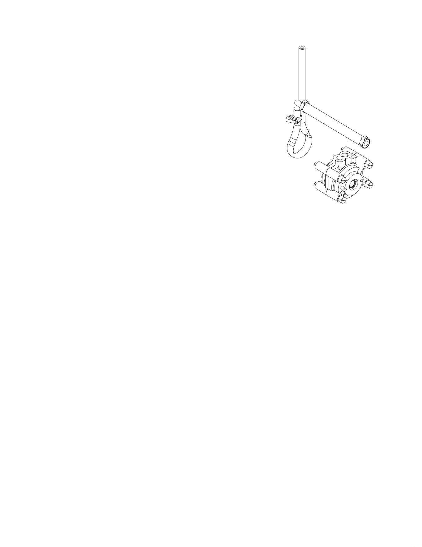
Annually: Replace Pump Tubing
1. Open dispenser door.
2. Remove all product containers and place them in a refrigerated
(35-40 degrees F [1.6-4.4 degrees C]) environment. Disconnect all
connections to ambient products from the bottle adapter.
3. Rinse all dispense stations using steps outlined in “DAILY RINSE
PROCEDURE”.
4. Disconnect dispenser from power source.
5. Remove the dispense platform cover.
6. Disconnect the dispense platform water line(s) from the
supply line inside the refrigerated cabinet and disconnect
the wiring connection(s) from the cabinet receptacle(s).
7. Remove the mounting screw(s) securing the dispense platform(s)
to the cabinet .
8. Pull the dispense platform(s) completely out of the cabinet and
place it on a flat work surface.
9. Close the dispenser door.
10. Remove the 4 screws securing the pump head.
11. Gently pull the pump head apart.
12. Gently pull the pump tube from around the pump’s rotor.
13. Release the clamps securing the old pump tubing to the
plastic elbows.
14. Pull the plastic elbows from the old pump tubing, and discard the
old pump tubing.
15. Insert the plastic elbows into the new pump tubing and secure it
with the clamps.
NOTE: Obtain new parts using the Illustrated Parts Catalog listed at
www.bunn.com.
16. Gently wrap the new pump tubing around the pump’s rotor.
17. Reassemble the pump housing onto the platform assembly.
18. Repeat steps 10 through 17 for the remaining pump(s).
19. Replace the dispense platform(s) into the refrigerated cabinet,
making sure to reconnect all electrical and water connections.
20. Replace the dispense platform cover.
21. Turn power on to dispenser.
22 Install containers of rinse water, run each station and check for
leaks. Repair leaks as necessary.
23. Replace product shelf and product containers. Reconnect any
connections to ambient product containers.
24. Prime the pumps as described in “PRIMING” in the Initial
Fill Section.
PREVENTIVE MAINTENANCE
082218

17
Frozen Concentrates
NOTE: Loading frozen concentrate in the product cabinet may cause damage to the machine. This damage
is not covered by warranty.
1. Thoroughly mix the thawed concentrate by vigorously shaking the product container.
2. Open the dispenser door.
3. Prior to placing the product container in the dispenser, make sure that the o-ring on the container adapter
is lubricated. This will ease removal of the container when it becomes necessary.
4. Place the product container in the desired position and press it firmly into the bottle adapter opening.
5. Open the vent hole in the product container. (If required).
NOTE: Concentrate in the container must be completely thawed and be within the temperature range of
35-40 degrees F (1.6-4.4 degrees C.) Product outside of this temperature range, especially below, may
produce an “out of ratio” drink.
Ambient Concentrates (Optional)
1. Install an Ambient Concentrate Conversion Kit (BUNN-O-MATIC part number 33699.0002) per the
instructions provided in the kit.
2. Attach the concentrate product hose to the appropriate concentrate line located at the rear of
the dispenser.
3. Attach the other end of the product hose to the product container through an appropriate fitting.
NOTE: Although the dispenser is designed to accept ambient concentrates, the Nitro Coffee cascade per-
formance may be reduced due to ambient product mixing with the cold nitrogenated water.
PRIMING
1. Open the dispenser door
2. Load concentrate per instructions in section titled Loading.
3. Close the dispenser door.
4. Place a large container under the appropriate dispense nozzle. Pull and hold the tap handle, until concentrate
dispenses from the dispense nozzle.
NOTE: This may take several seconds, depending on the installation and set pump speed.
LOADING PRODUCT CONTAINERS
082218
18
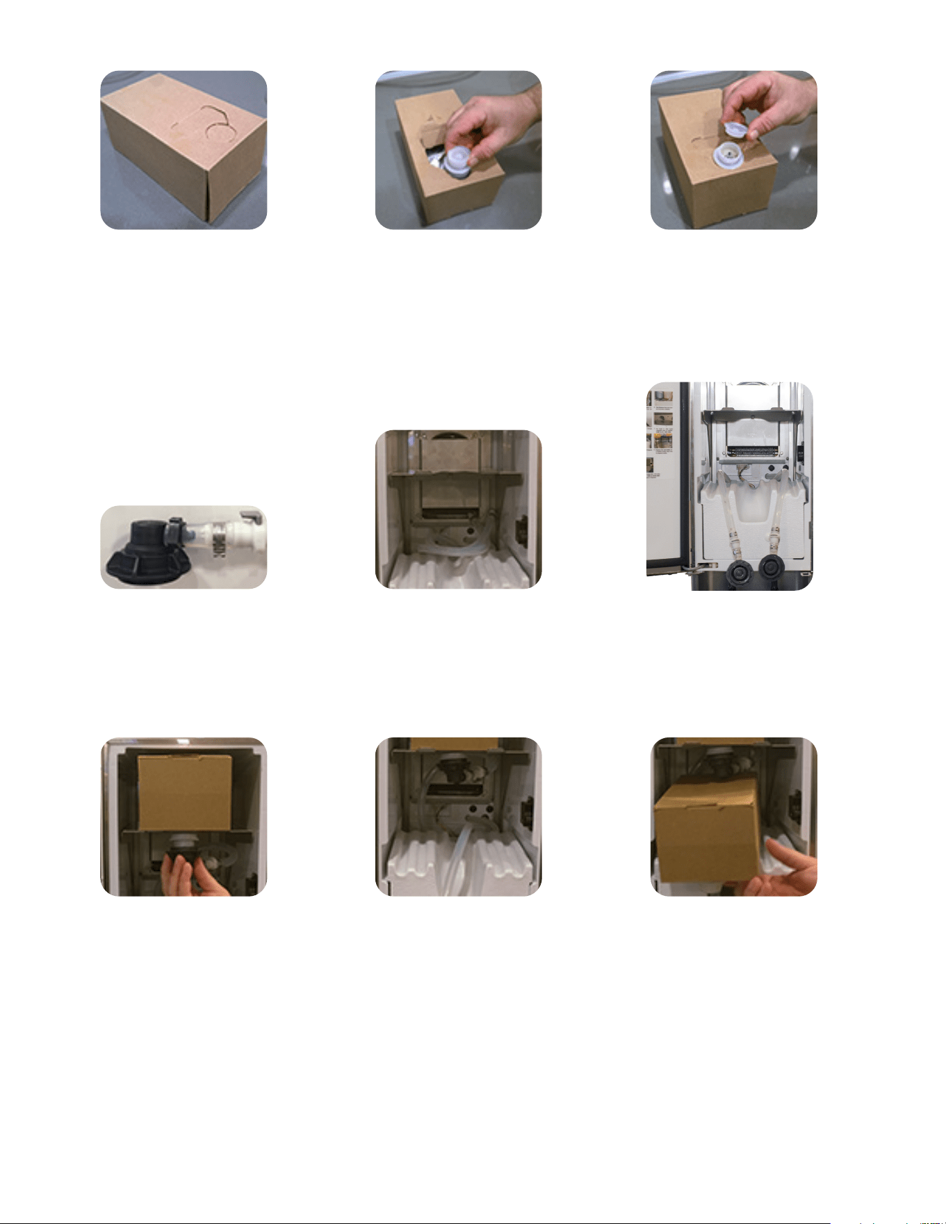
LOADING BAG-IN-BOX (BIB) - SCHOLLE QUICK DISCONNECT FITTING ASSEMBLY
STEP 1 STEP 2 STEP 3
Prepare Bag-In-Box (BIB) for
installation by thoroughly mixing
concentrate by vigorously
shaking the product Bag-In-Box.
Next, locate the perforated hole
area on the box and release.
Pull the product BIB connector
through the hole and slide into
position, secure the BIB connector
in the cardboard opening by
engaging the cardboard tab into
the BIB connector groove.
Remove the cap/seal from the
Bag-In-Box connector and discard.
STEP 4 STEP 5 STEP 6
Locate the SCHOLLE quick
connect fitting assemblies in the
door parts box.
Open the dispenser door and locate
the left and right product tubes
inside the cabinet.
Connect a SCHOLLE quick
connect assembly to the left
and right product tube.
STEP 7 STEP 8 STEP 9
First, place the BIB on the top shelf
with the bag receiver connector
towards the front, facing downward.
Use a little of the Lubri-Film to
make sure that the receiver
connector is lubricated. Grab the
left product tube with SCHOLLE
mating connector and screw
clockwise onto the bag receiver
connector until hand-tight.
Next, ensure right product tube is
positioned in the lower shelf center
cavity before placing BIB on lower
shelf with BIB connector facing
downward.
Pull BIB off shelf enough to be able
to connect the right product tube
with the SCHOLLE mating
connector. Use a little of the
Lubri-Film to make sure that the
receiver connector is lubricated.
082218
19
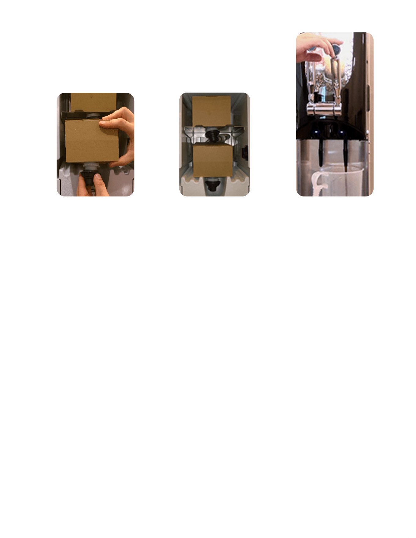
LOADING (Cont.)
STEP 10 STEP 11 STEP 12
Grab right product tube with
Scholle bag receiver connector
and screw clockwise onto mat-
ing BIB connector until hand-
tight. Place lower BIB back into
position with the SCHOLLE
connector positioned in cavity
of product shelf.
Ensure left and right product
tubes are properly routed without
any kinks.
Ensure the dispense lockout
switch is in the ON position before
closing the door.
Next, go to Priming Concentrate
Lines. Place empty container
under appropriate nozzle to be
ready for Priming.
PRIMING CONCENTRATE LINES
1. Open the dispenser door
2. Load concentrate per instructions in section titled Loading Bag-In-Box with SCHOLLE
Quick Disconnect Fitting Assembly.
3. Ensure the dispense lockout switch is in the On position.
4. Close the dispenser door.
5. Place a large container under the appropriate dispense nozzle. Pull and hold the tap handle, until
concentrate dispenses from the dispense nozzle.
NOTE: This may take several seconds, depending on the installation and set pump speed.
082218
20
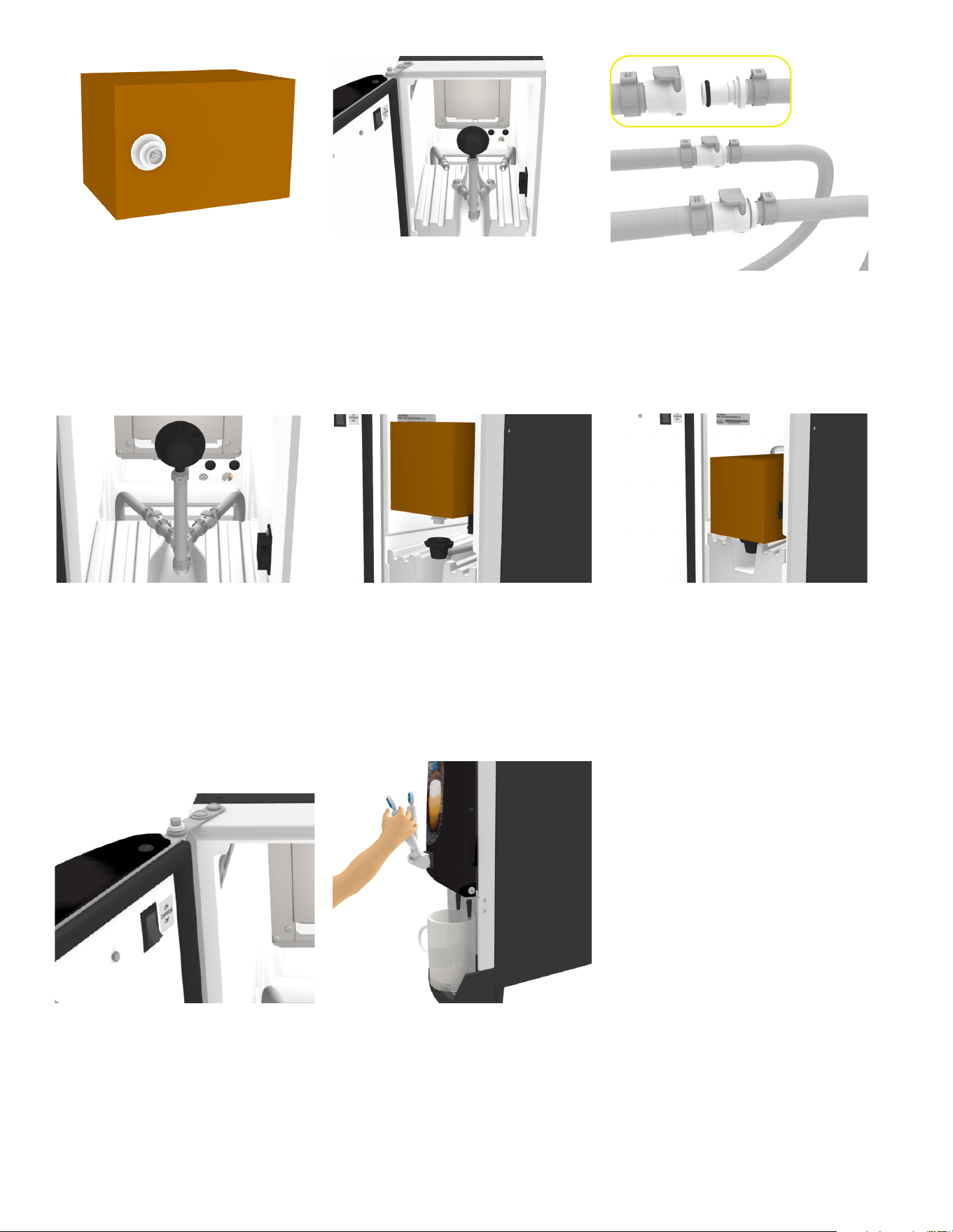
LOADING BAG-IN-BOX (BIB) - Scholle "Y" Fitting QUICK DISCONNECT ASSEMBLY
STEP 1 STEP 2 STEP 3
First, mix concentrate by vigorously
shaking the B-I-B. Next locate the
perforated area and release. Locate
Scholle connector and set into
position and secure with perforated
tab. Remove BIB cap/seal.
Locate the Scholle quick connect
"Y" fitting assembly in the door
parts box. Open the dispenser
door and ensure the Scholle con-
nector is facing inside the cabinet.
STEP 4 STEP 5 STEP 6
Ensure the "Y" fitting is setup cor-
rectly by verifying the Scholle con-
nector is still facing the inside of the
cabinet.
Place B-I-B on shelf with B-I-B
connector facing up. Grab the
Scholle connector and screw onto
the mating B-I-B connector.
STEP 7 STEP 8
Ensure left and right product tubes
are properly routed without any
kinks and that the Scholle connec-
tor rests within the groove of the
shelf.
Located on the inside upper right
hand corner of the door, ensure
the dispense lockout switch is in
the On position before closing
the door.
Next, go to Priming Concentrate
Lines. Place empty container
under appropriate nozzle to be
ready for Priming.
082218
Attach the "Y" fitting to the product
tubing.
21
Adjusting Water Flow
Using Flat Blade Screwdriver
Water Flow Testing and Adjustment - Still Side Only
NOTE: Purge all dispense stations to remove air
from water line before making initial adjustments.
NOTE: Some models are equipped with Nitro
dispense valves at both dispense stations.
Nitro dispense valves do not require any water
flow adjustment.
1. Place a graduated measuring cup or the large
chamber of the empty brixing cup (BUNN-O-MATIC
part number 33095.0000) under the appropriate
dispense nozzle. Place the Program switch in the
ON position.
2. Pull and release the desired tap handle three times.
3. The selected position will dispense water
(no concentrate) only for 3 seconds.
ADJUSTMENT & OPTIONAL SETTINGS
4. Measure the water dispensed. Suggested target is 133 ml (4.5 oz) per 3 seconds flow rate.
5. Adjust the water flow rate Fig 17, (counterclockwise to increase flow rate; clockwise to decrease flow rate)
to the corresponding product mix ratio.
6. Repeat steps 1 through 5 as necessary until the correct water flow rate is achieved.
7. Place the Program switch back into the OFF position.
Pump Speed Adjustment
1. Disconnect the dispenser from the power source.
2. Remove the drip tray.
3. Remove the two screws securing the splash panel and remove the splash panel
4. Locate the adjustment knobs on the circuit board.
NOTE: Start with the adjustment dial in the nine o'clock position.
5. Turn the adjustment knobs clockwise to increase speed and counterclockwise to decrease speed.
NOTE: Use the two left most knobs to make pump speed adjustments. Left most being station #1
(left side dispense) and second from left being station #2 (right side dispense).
6. Reinstall the splash panel and drip tray and reconnect the dispenser to the power source.
LOADING (Cont.)
PRIMING CONCENTRATE LINES
1. Open the dispenser door
2. Load concentrate per instructions in section titled Loading Bag-In-Box with ASTRA
Quick Disconnect Fitting Assembly.
3. Ensure the dispense lockout switch is in the On position.
4. Close the dispenser door.
5. Place a large container under the appropriate dispense nozzle. Pull and hold the tap handle, until
concentrate dispenses from the dispense nozzle.
NOTE: This may take several seconds, depending on the installation and set pump speed.
082218

22
Ratio Dispense Test Set Up Procedure
1. Place the Program switch in the ON position.
2. Water flow rate should be factory pre-set to 133 ml (4.5 oz) per 3 second dispense. To verify, place a
graduated measuring cylinder under the dispense nozzle, pull and release the tapper handle 3 times. The
dispenser will then dispense an amount of water for 3 seconds. Record the water output for later reference
on each dispense head.
3. Pull and release the tapper handle 6 times. The dispenser will then dispense an amount of concentrate for 3
seconds.
• For best results, discard the first two samples before recording output. Repeat the same practice after
every adjustment.
4. Record the amount dispensed.
NOTE: Measuring in milliliters is required for accuracy.
5. Refer to the Ratio chart below to confirm proper volumes for desired ratios. Concentrate amounts for each
ratio are highlighted in yellow under the ratio number.
6. To increase or decrease the product output, refer to Step 10 of SET-UP INSTRUCTIONS.
7. Place the Program switch back to the OFF position.
Brix Dispense Test Set Up Procedure
1. Load the concentrate in the dispense station. Dispense until the finished drink is flowing from the dispense
nozzle.
2. Dispense a typical cup size and discard.
3. Dispense another sample and measure the Brix using a refractometer. Best practice is to allow samples
dispensed with nitrogen to settle before taking a measurement.
• Once a sample is placed on the refractometer, wait until it reaches temperature to determine current
Brix measurement (about 1-2 minutes).
• Many refractometers include a thermometer on board and will help indicate that the sample is at room
temperature and ready to be tested. (See refractometer manual for more details on usage.)
4. To increase or decrease the product output, refer to Step 10 of SET-UP INSTRUCTIONS.
5. Continue making pump speed adjustments and measuring samples until desired Brix target is reached.
ADJUSTMENT & OPTIONAL SETTINGS (Cont.)
082218
3 sec. water
Ratio Target
dispense in
milliliters
4+1 5+1 6+1 7+1 8+1 9+1 10+1 11+1 12+1 13+1
127 31.8 25.4 21.2 18.1 15.9 14.1 12.7 11.5 10.6 9.8
130 32.5 26.0 21.7 18.6 16.3 14.4 13.0 11.8 10.8 10.0
133 33.3 26.6 22.2 19.0 16.6 14.8 13.3 12.1 11.1 10.2
136 34.0 27.2 22.7 19.4 17.0 15.1 13.6 12.4 11.3 10.5
139 34.8 27.8 23.2 19.9 17.4 15.4 13.9 12.6 11.6 10.7
14+1 15+1 16+1 17+1 18+1 19+1 20+1 21+1 22+1 23+1
127 9.1 8.5 7.9 7.5 7.1 6.7 6.4 6.0 5.8 5.5
130 9.3 8.7 8.1 7.6 7.2 6.8 6.5 6.2 5.9 5.7
133 9.5 8.9 8.3 7.8 7.4 7.0 6.7 6.3 6.0 5.8
136 9.7 9.1 8.5 8.0 7.6 7.2 6.8 6.5 6.2 5.9
139 9.9 9.3 8.7 8.2 7.7 7.3 7.0 6.6 6.3 6.0
24+1 25+1 26+1 27+1 28+1 29+1 30+1 31+1 32+1 33+1
127 5.3 5.1 4.9 4.7 4.5 4.4 4.2 4.1 4.0 3.8
130 5.4 5.2 5.0 4.8 4.6 4.5 4.3 4.2 4.1 3.9
133 5.5 5.3 5.1 4.9 4.8 4.6 4.4 4.3 4.2 0.0
136 5.7 5.4 5.2 5.0 4.9 4.7 4.5 4.4 4.3 4.1
139 5.8 5.6 5.3 5.1 5.0 4.8 4.6 4.5 4.3 4.2

23
Foam Height Adjustment
NOTE: Only Later Style dispensers have an internal adjustable N
2
gas pressure regulator verses early style
dispensers having a non-adjustable N
2
gas pressure regulator.
If you are not getting any foam, please ensure that your primary N
2
gas supply is properly connected and
turned on. Dispensers with an internal adjustable N
2
gas pressure regulator can be adjusted to deliver a
different foam height on a dispensed cold draft beverage.
ADJUSTMENT & OPTIONAL SETTINGS (Cont.)
Dispenser Lockout
Dispense functions of the dispenser can be turned-off to prevent unauthorized use of the dispenser, while
keeping the refrigeration system running.
1. Locate the Dispense Lockout switch inside the door at the top of the dispenser.
2. Place the switch in the OFF position to prevent dispensing.
3. Place the switch in the ON position to allow dispensing.
NOTE: This switch will also operate the door lights on models equipped with this feature and actuates
water bath auto fill.
Fig.1
082218
1. After product loading and priming procedures have
been performed, dispense a full drink and observe
foam height after the surge is finished.
2. Remove right side panel and locate adjustment knob
of gas regulator. Fig.1
3. Pull knob out to unlock and allow adjustment.
4. For more foam, turn knob clockwise no more than
1/4 turn. For less foam, turn knob counterclockwise
no more than 1/4 turn.
5. Dispense another full drink and observe change in
the foam height.
6. If foam is still not at the desirable height, go back to
Step 4.
7. When desired foam height is achieved, push in
regulator knob to lock it in place and reinstall
side panel.

24
When planning on removing and transporting a dispenser from the field, a few steps must be taken to
ensure equipment cleanliness, safety of the equipment and service personnel. The dispenser will have an
approximate 8lb. ice bank that will need to melted prior to removal. This usually requires the dispenser to be
unplugged from electricity for 48 hours prior to removal date allowing the 8lb. ice block to fully melt within
the water bath.
Nitrogen cylinder is under extremely high vapor pressure which will need to be handled with care during
disconnect from the dispenser. The Nitrogen cylinders will have a DOT label identifying the gas and hazards.
Steps for Decommissioning the nitron
2
Cold Draft Dispenser 48 Hours Before Transportation
Step 1: Remove the product containers or BIB's from the dispenser cabinet and store away in a refrigerated
environment if you plan on using again.
Step 2: Locate the N
2
supply cylinder and verify it only supplies nitrogen to the BUNN nitron
2
Cold Draft
dispenser. Turn the main cylinder On/Off valve to the Off position. Place an empty container under the
dispense nozzles. Pull the "Nitro Coffee" tap handle to relieve the pressure. Disconnect the nitrogen
supply line to the dispenser and cap the dispenser nitrogen inlet fitting.
Step 3: Next, disconnect the nitrogen pressure regulator from the cylinder. Pack the tubing and regulator for
transport. Inform the location manager or owner that the Nitrogen cylinder is disconnected and should
be properly stored until gas supplier can pick up.
NOTE: During removal, if the cylinder is empty, tag the cylinder as "Empty".
Step 4: Perform the dispenser cleaning/sanitizing procedure as instructed in the nitron
2
Cold Draft
Installation & Operating Guide.
NOTE: By performing the cleaning/sanitize procedure prior to dispenser removal will reduce the
amount of time, labor and parts in reconditioning the dispenser to get it ready for the next placement
out in the field.
Step 5: There will be an approximate 8 lb. ice block inside the water bath that will take 48 hours to melt.
Locate the dispenser compressor On/Off switch behind the lower splash panel, toggle the switch to
the Off position. Unplug the dispenser from the power supply.
Step 6: Turn Off the main water supply to the dispenser. Pull a tap handle to relieve pressure in the water
line. Disconnect the water source to the dispenser and cap off the water source & dispenser fitting
for extra protection.
Step 7: Place sign on dispenser. (Decommission In-Process, Return On _______ For Pick Up).
NITRON
2
COLD DRAFT DECOMMISSION PROCEDURE
082218
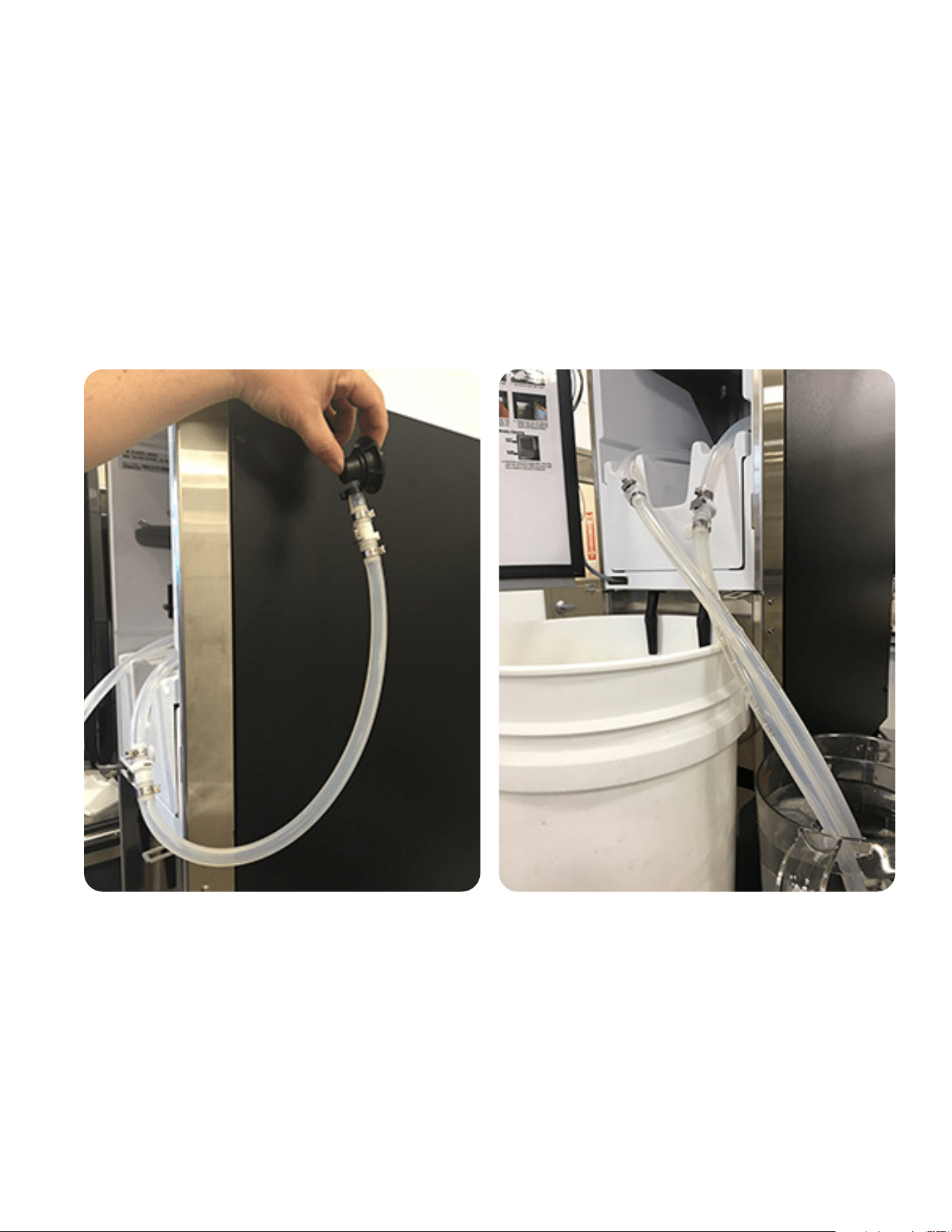
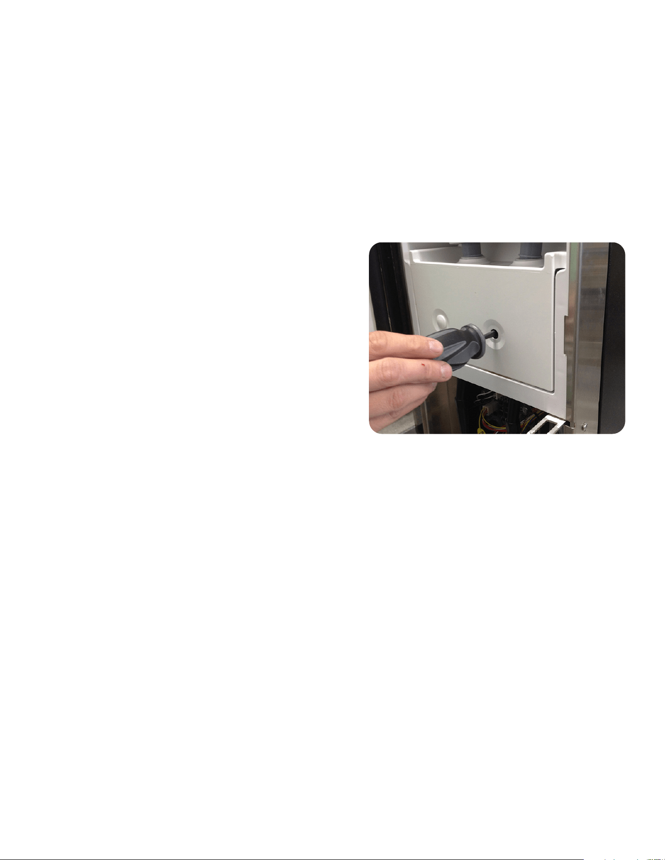
25
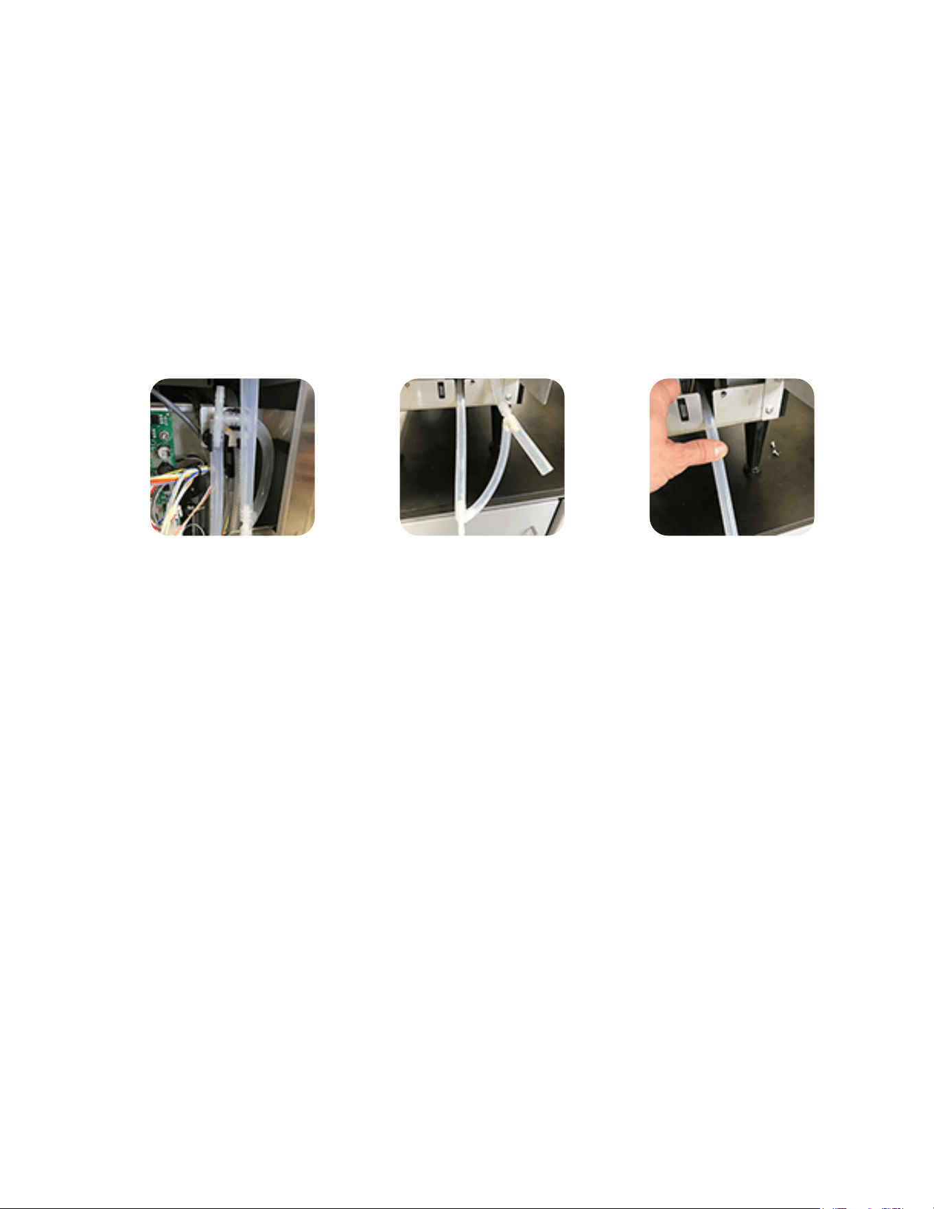
Step 3: Once water has stopped draining from the drain tube, reconnect the "T" barbed fitting on the sight tube
and position it back to its original position (photo 1). Reinstall the lower splash panel and prepare the
machine for loading. Secure the dispenser in an upright position in the transport vehicle.
1 2 3
Steps For Transportation
Step 1: Return to location with a helper to assist with removal of dispenser from the current location.
NOTE: Helper is only needed if service technician does not have the necessary equipment to lift,
move and secure a 130lb dispenser safely.
Step 2: Now that the ice block is melted, you will need to drain the water bath before removing and pack-
ing the dispenser for transport. The water bath will have approximately 2-1/2 to 3-gallons of water.
Remove the lower splash panel to access the sight gauge tube (photo 1). Pull the sight tube down and
position in knock-out (photo 2) to drain the water bath from the tank into an empty 5-gallon bucket.
As an alternative option, you can disconnect the sight tube from the "T" barbed fitting (increase flow)
and hold the drain tube down (photo 3) to drain the water into an empty 5-gallon bucket.
082218
NITRON
2
COLD DRAFT DECOMMISSION PROCEDURE (Cont.)

26
DISPENSER FAULT CODES
NOTE: All LED flashing sequences include a 3-second delay between flash codes.
1. 1 flash of the circuit board mounted bath LED’s and 1 flash of the door mounted blue LED’s.
• Bath Sensor Open
Possible Cause(s): Bath sensor not connected to the main board | Bath sensor failed.
2. 2 flashes of the circuit board mounted bath LED’s and 2 flashes of the door mounted blue LED’s.
• Bath Sensor Shorted
Possible Cause(s): Bath sensor failed | Shorted bath sensor wires.
3. 1 flash of the circuit board mounted cabinet LED’s and 3 flashes of the door mounted blue LED’s.
• Cabinet Sensor Open
Possible Cause: Cabinet sensor not connected to the main board.
4. Circuit board mounted cabinet LED’s will flash slowly. 4 flashes of the door mounted blue LED’s.
• Cabinet > 50 degrees for 4 hours.
This fault will stop all dispense functions.
Possible Cause(s): Cabinet fan not running | Water bath pump not running | Check compressor/WB
pump switch to confirm it is On | Water bath is low.
Troubleshoot by powering the dispenser down and back up to reset the fault.
5. 5 flashes of the door mounted LED’s.
• Left Concentrate Pump Stalled
This fault will reset itself after 5 seconds.
Possible Cause: Peristaltic pump failed or stalled.
6. 6 flashes of the door mounted LED’s.
• Right Concentrate Pump Stalled
This fault will reset itself after 5 seconds.
Possible Cause: Peristaltic pump failed or stalled.
7. 7 flashes of the door mounted LED’s if the bath has not reached proper level after 4 minutes.
• Refill Fault Dispenser will not allow additional bath filling until this fault is reset.
Possible Cause(s): Water line to machine turned off.
Water not connected to dispenser | Water flow/pressure source too low | Bath fill valve failed.
Troubleshoot by powering the dispenser down and back up to reset the fault. Bath will start filling 30
seconds after power up.
Fault Code LEDs
082218
27
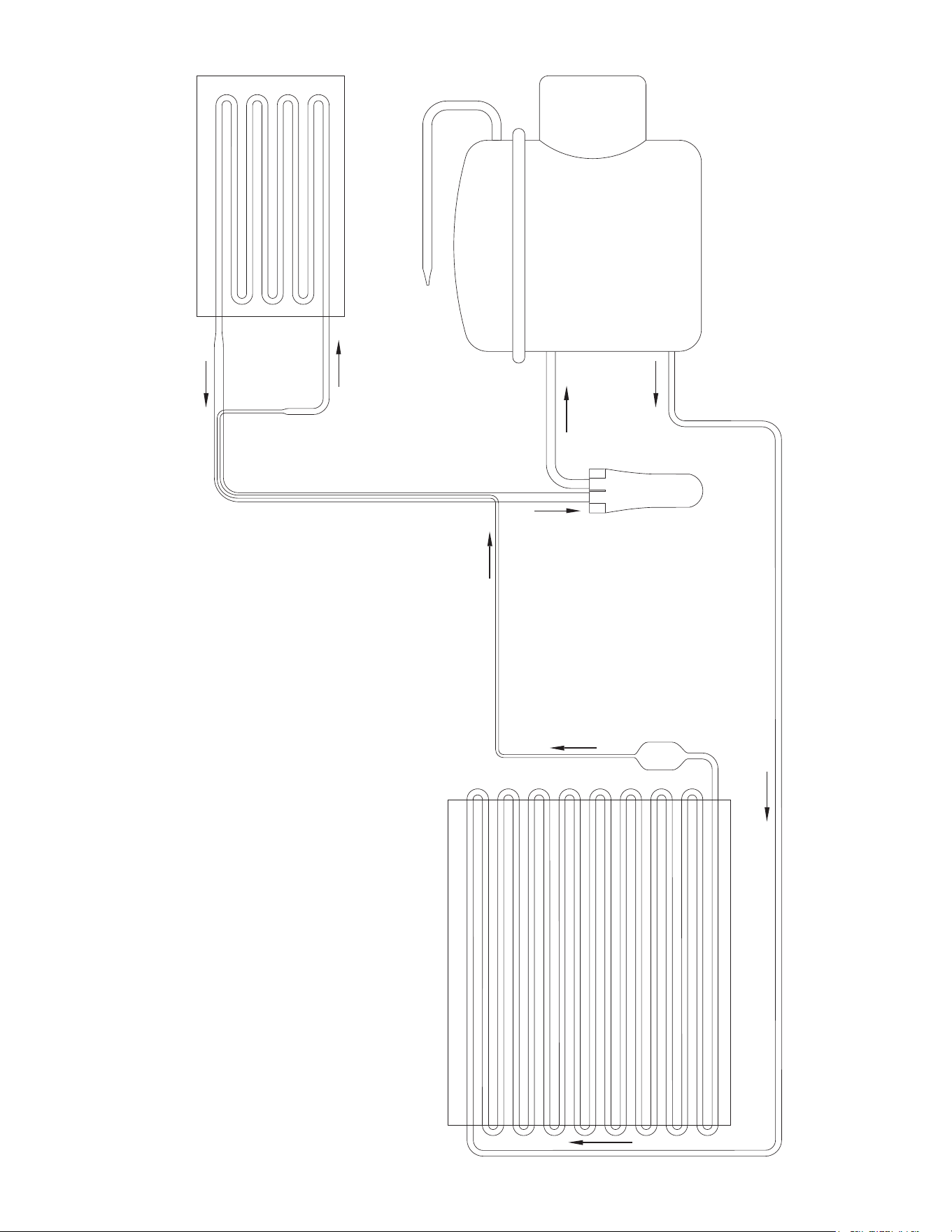
COOLANT SCHEMATIC DIAGRAM
CONDENSER
SUCTION
ACCUMULATOR
COMPRESSOR
EVAPORATOR
PROCESS TUBE
33464.0000A 09/00 ©2000 Bunn-O-Matic Corporation
FILTER
DRYER
082218
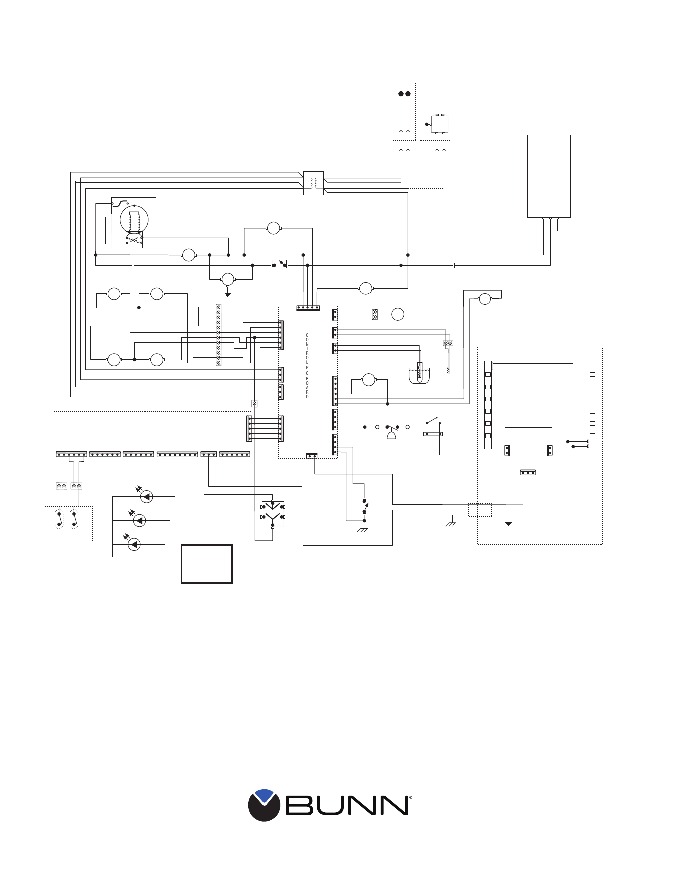
SCHEMATIC WIRING DIAGRAM
J6-1
J6-3
CON
TROL
P
C
B
O
ARD
J5-1
J5-4
J15-1
J15-4
J2-1
J2-6
GRN
WHI/ORN
LEFT
DISPENSE
RIGHT
DISPENSE
LEFT
DISPENSE
RIGHT
DISPENSE
YEL YEL
WHI/VIO
RECIR.
PUMP
BRN
WHI
BLK
J1-1
J1-5
WHI
J3-1
J3-2
WHI/BLK
ORN
WHI/VIO
WHI/ORN
VIO
RED
RED
RED
WHI/RED
BLK
WHI RED/BLK
RED/BLK
YEL
WHI/BLU
BLU
RED
MOTOR
CONDENSOR FAN
RED/BLKBLU/BLK
BLU/BLK
J7-1
J7-2
J9-1
J9-2
PUMPPUMP
FAN
AUXILLARY
CONTROL BOARD
PULL & HOLD BODY
t
t
WHI/BLK
GRY
WHI/RED
WHI/RED
WHI/BLU WHI/BLU
WHI/YEL
WHI/YEL
BLU
BLU
PNK
YEL
PNKYEL
YEL
BLK or ORN
WHI
CABINET
THERMISTOR
WATER BATH
THERMISTOR
WHI WHI
WHI
BLK
WHI
BLK
GRN
54267.0000B 07/17 © 2017 BUNN-O-MATIC CORPORATION
BLU/BLK
1
BLK
BLK
BRN
WHI
WHI
BLK
BLK
WHI
GRN
1
BLK
COMPRESSOR/WATER BATH
SWITCH
K1
SCHEMATIC WIRING DIAGRAM
NITRON
2
COLD DRAFT COUNTERTOP DISPENSER
1
12
WHI/VIO
WHI/VIO
VIOVIO
VIO
WHI/ORNWHI/ORN
YELYEL
REDRED
REDRED
ORNORN
ORN
SOL SOL
WATER INLET
VALVE
WATER BOOSTER
PUMP
WATER BOOSTER
PUMP RELAY
BRN WHI
SOL
BLK
TRANSFORMER
WHI
BLU
WHI/BLU
L
O
A
D
L
I
N
E
WHI
WHI/BLK
K1
120V
MODELS
N
A B
A B
A B
L1
WHI/GRN
BRN/WHI
A B
220-230V
MODELS
GRN/YEL
NL1GND
BRN
BLU
EMI
FILTER
120 VOLTS AC
or
220-230 VOLTS AC
2 WIRE
SINGLE PHASE
W/Tape Over-Laminate
Thermal Transfer Stock
Black Ink
Finished Size: 6.5" x 6.0"
~ 40% Reduction
J1-1
J1-3
J5-1
J5-5
J4-1
J4-5
J3-1
J3-5
J2-1
J2-5
J8-1
J8-5
J8-8
Lited Doors
LEFT
DISPENSE
RIGHT
DISPENSE
BLK
BLK
BLK
BLK
BLK
BLK
BLK
BLK
RED
RED
BLK
BLK
GRNGRN
WHIWHI
BRNBRN
BLK
BLK
PROGRAM
SWITCH
J12-1
J12-3
WHI/BLU
BLU
START
RUN
COMPRESSOR ASSY
LIMIT
THERM.
COMPRESSOR
MOTOR
3
PTC
ASSY
4
56
2
1
N
GRN/YEL-16
J8-1
J8-2
Chassis
Ground
Chassis
Ground
Door
Ground
Regulator
Board
J3-1
J2-1
J1-1
_
+
_
+
BRN
BRN
DISPENSE
LOCKOUT
SWITCH
J11-1
J11-5
J6-1
J6-5
BLK
RED
BLU
BLU
BLU
BLU
BLU
YEL
ORN
J13-1
J13-6
L.E.D.
L.E.D.
DISPENSE AREA
DISPENSE AREA
NITROGEN PRESSURE
L.E.D.
WATER BATH
FILL
NITROGEN
PRESSURE
SENSOR
BATH
FILL
FLOAT
SOL
1 2
K2
K2
WHI/BLU
WHI/BLU
WHI/RED
WHI/RED
RED
RED
RED
RED