Revision: B0 MP05-00001
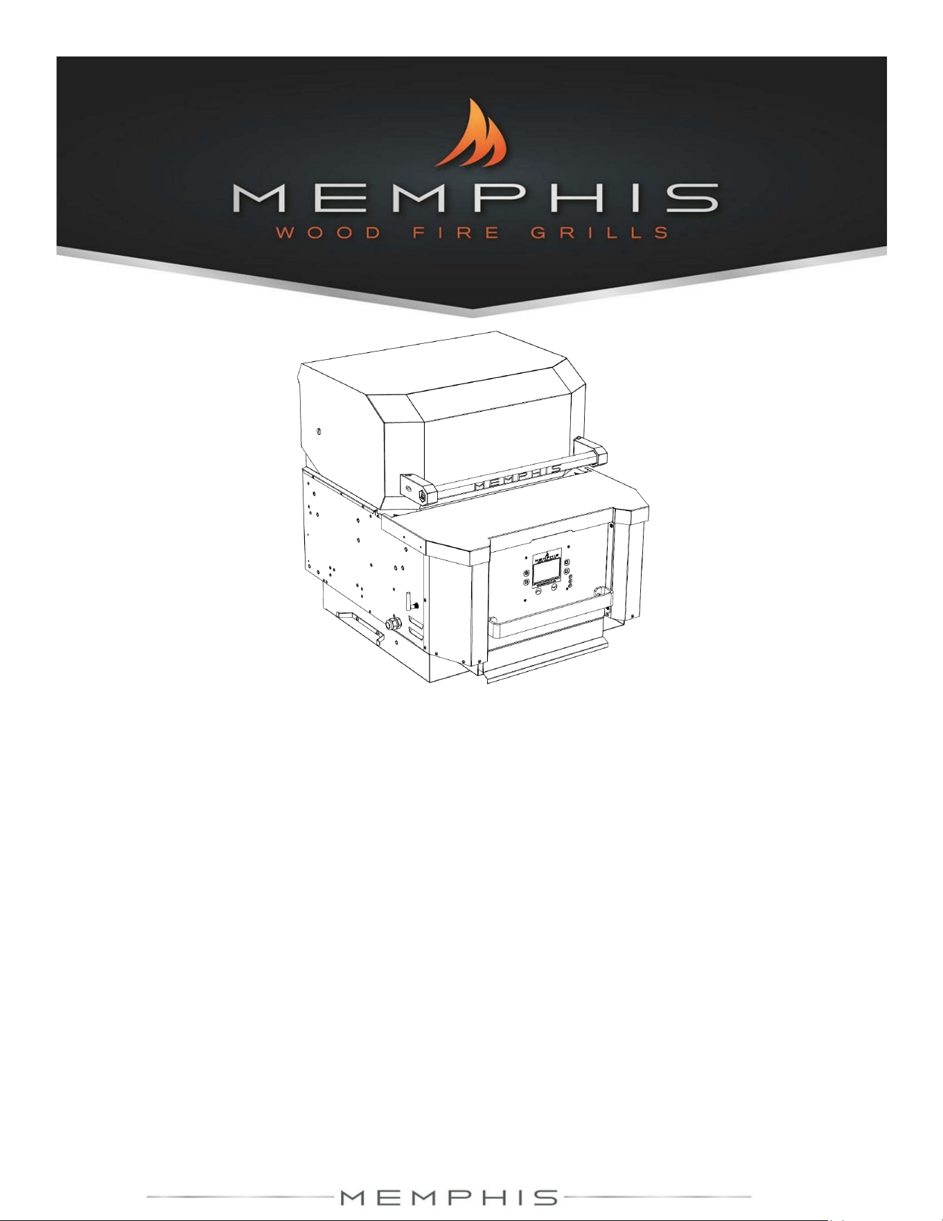
Memphis Elevate™ ITC 2
Model Number MG01-06-001
Read all instructions before installing and using this appliance. Save these instructions for future reference.
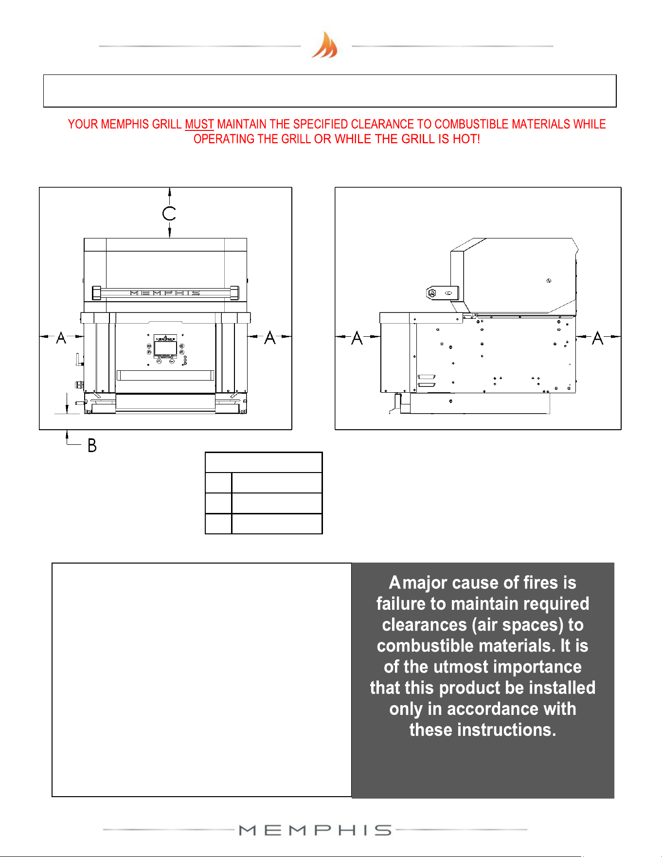
A MAJOR CAUSE OF FIRES IS FAILURE TO
MAINTAIN REQUIRED CLEARANCES (AIR
SPACES) TO COMBUSTIBLE MATERIALS. IT
IS OF UTMOST IMPORTANCE THAT THIS
PRODUCT BE INSTALLED ONLY IN
ACCORDANCE WITH THESE INSTRUCTIONS.

2
Table of Contents
Warranty Registration 3
Memphis Elevate™ Overview 4
Clearance to Combustibles 5
Electrical Installation Requirement 6
Memphis Elevate Grill Head
Parts List 7
Assembly Instruction 8-9
Memphis Wi-Fi Setup Guide 10
Memphis Controller Diagram 11-12
Memphis Elevate Built-In Brackets
Overview 13
Cutout Dimensions 14
Dimensions 15
Parts List 16
Assembly Instructions 17-19
Memphis Elevate Leg Assembly
Overview 20
Dimensions 21
Parts List 22
Assembly Instructions 23-27
Memphis Elevate Surround Assembly
Overview 28
Dimensions 29
Parts List 30-31
Assembly Instructions 32-35
Memphis Elevate Cabinet Assembly 36
Link to Product Manual Updates 37

3
Scan for Warranty
Registration
Stop!
Scan the QR Code above now
to secure your grill warranty registration.
Or register online at:
https://memphisgrills.com/support-resources/warranty-registration/
4
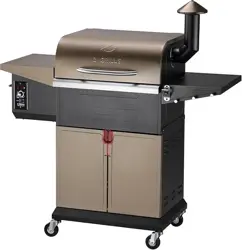
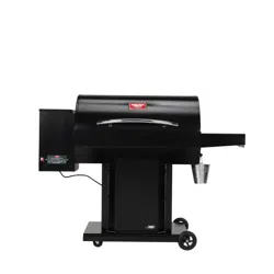
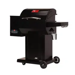
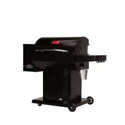
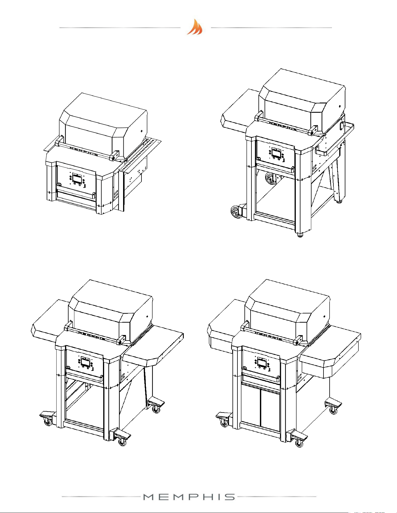
Memphis Elevate™ Overview
MODEL NUMBER: MG11-06-001
DESCRIPTION: Built-In Bracket Assembly
MODEL NUMBER: MG11-06-002
DESCRIPTION: Leg Assembly
MODEL NUMBER: MG11-06-003
DESCRIPTION: Surround Assembly
MODEL NUMBER: MG11-06-004
DESCRIPTION: Cabinet Assembly
5
Below are some guidelines to ensure
safe operation of your Memphis Grill:
• The grill is to be supported by the casters or fixed
wheels and leveling feet depending on which
assembly is purchased.
• Grill casters are to be locked while the grill is in use
or while the grill is hot.
• It is recommended that the grill be placed on a
non-combustible surface.
• Operating the grill under a combustible ceiling or
overhang is NOT recommended.
• Maintain the minimum clearance to combustible
materials specified above.
Combustible Material is wood, dry wall, siding or any other material that has the ability to catch fire.
Clearance to Combustible Materials
DIMENSIONS
A 18” [45.8 cm]
B 3/8” [1.0 cm)
C 30” [76.2 cm]

6
Electrical Installation
Dedicated Electrical Circuit with GFCI Protected Outlet
A dedicated GFCI protected electrical circuit is REQUIRED for all Memphis Wood Fire Grills and
controller systems. This circuit should be installed by a Certified Electrician. Although the
Memphis Grill only uses about 5 amps of current during startup, any other equipment (refrigerator,
pool pump, fountains, etc.) with a high current draw, consistently or intermittently, from the same
electrical circuit can cause potential issues and/ or interruptions with the performance of the grill.
On/Off Switch Recommendation
For Built-in models, we recommend that an on/off switch be installed in a circuit that can
be easily disconnected from power when not in operation. This will prevent the buildup of
interference that could affect the controller’s operation.
7
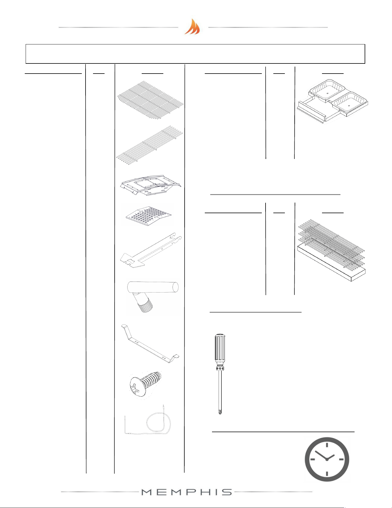
Grill Head Parts List
TOOLS REQUIRED
• Phillips Screwdriver or Drill
Description/ Part No. Qty: Picture:
4. Direct Flame
Insert VG4407
1
3. Savorizer®
VG4403
1
9. Meat Probe
ME10-00001
1
1. Main Grates
MA07-00003
1
2. Upper Grate
MD07-00008
1
5. Genie Tool
VG0594
1
6. Wi-Fi Antenna
VG9025
1
7. Cord Wrap
VG0173
1
8. #10 Screw
(SS) DS2186
2
Description/ Part No. Qty: Picture:
OPTIONAL ACCESSORIES
A. Extended
Grate Kit
MG33-01-004
3 grates
per box
ESTIMATED TIME REQUIRED
0.50 Hours
(excludes removal
of protective film)
Description/ Part No. Qty: Picture:
10. Ash Drawer
MG33-01-004
1
8
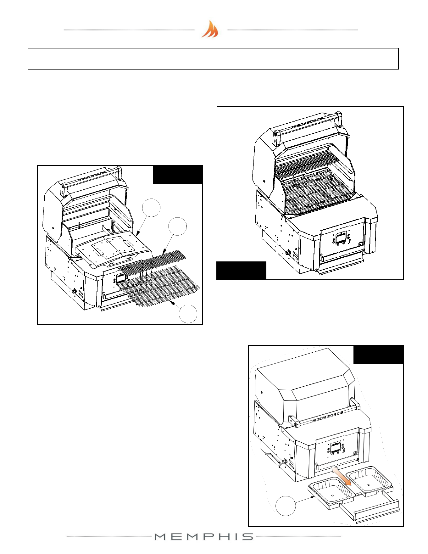
Grill Head: Assembly Instructions
Peel all plastic protective film prior to performing the assembly steps listed below. Refer to
page 7 for item part numbers, descriptions, and quantities.
Step 1) Remove Savorizer (Part 3) and grates
(Part 1 & Part 2) from inside the grill hood. To
remove the Savorizer, cut the four zip ties
holding it in place. Set aside the parts until
needed (See Figure 1a & 1b).
Figure 1a
Figure 1b
1
2
3
Step 2) Slide ash drawer (Part 10) from the grill. Remove
the plastic bag from the ash drawer. Slide ash drawer
back into the grill (See Figure 2).
Figure 2
10
9
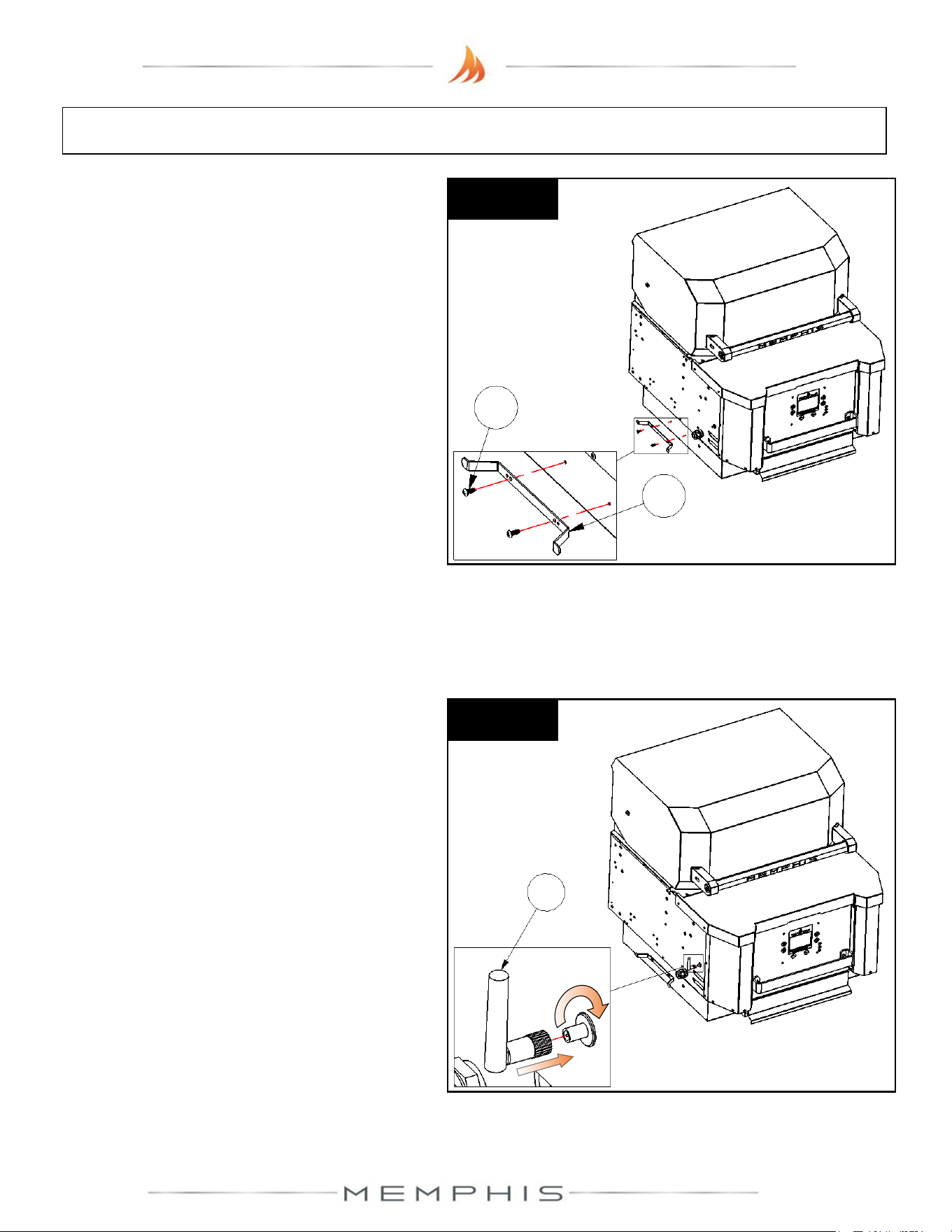
Grill Head: Assembly Instructions
Step 4) Thread Wi-Fi antenna (Part 6) to
bulkhead connector located on the Grill
Head’s left panel side (Figure 4).
Figure 4
6
Step 3) Attach cord wrap (Part 7) onto the
side of the grill using two screws (Part 8)
(See Figure 3).
7
8
Figure 3
10
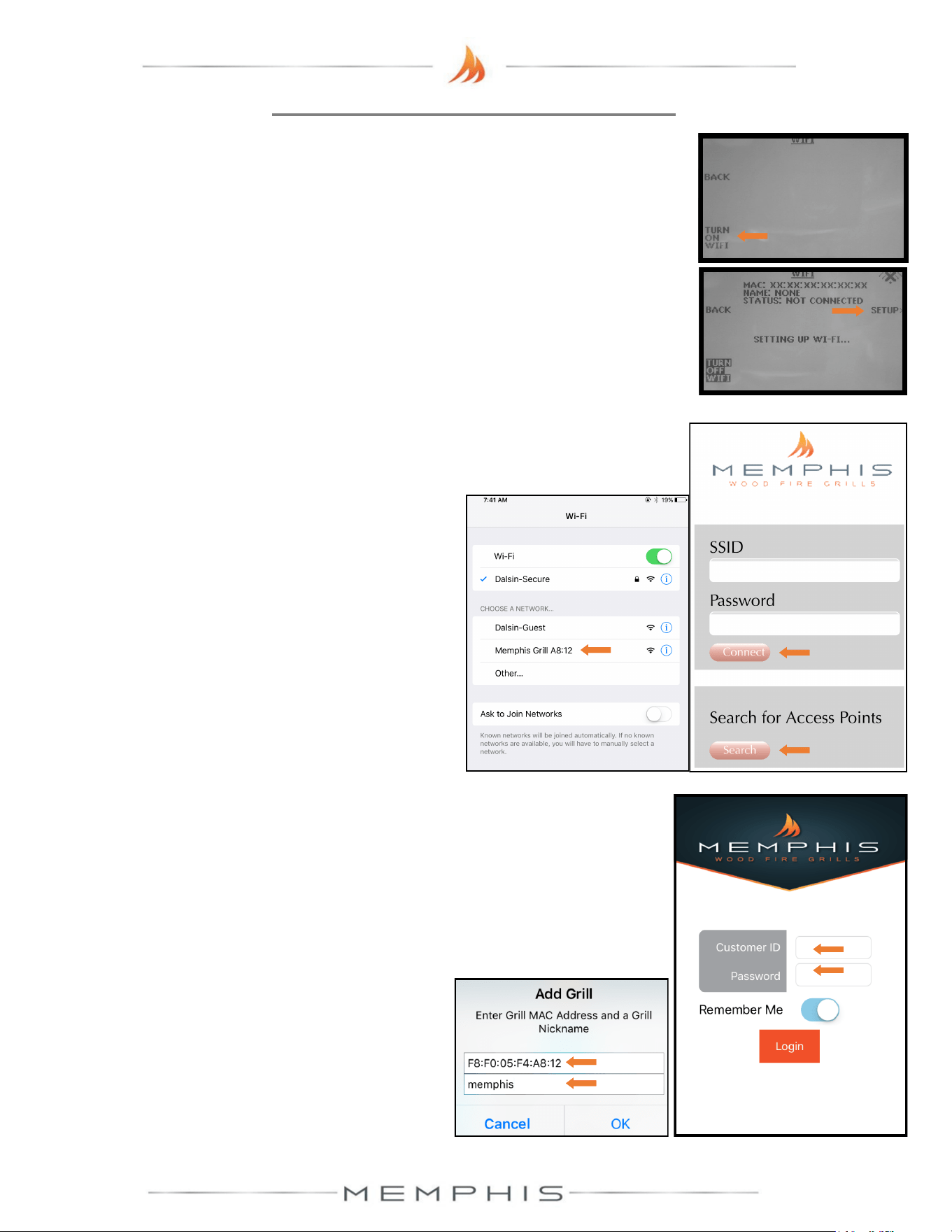
MEMPHIS WI-FI SETUP GUIDE
8) Download the “MEMPHIS GRILLS” App from the IOS App Store or Google Play Store.
9) Enter a valid email into the “CUSTOMER ID” field and create a password that you will use to log into
the app. After logging in, you will receive an email requiring you to confirm your email address before
continuing.
10) Once you click the confirmation link from your email, return to the app.
11) Log into the app again and you will be able to add your grill.
Enter the exact MAC Address and Name shown on the grill
controller.
4) Simply go to available Wi-Fi networks on your phone or tablet and select the network “Memphis Grill
XX:XX”. NOTE: The XX:XX characters will match the last 4 digits shown on the grill controller next to MAC.
5) Once selected, the grill’s network will automatically bring you to a page where you will connect your grill to
your Wi-Fi network. Search for all networks in range by hitting
“Search”, and all networks in range are displayed. Click on the
network desired and it will auto populate the “SSID” field with your
selection. Enter your network’s password if you have one. If the
network does not require a password, leave the password field blank.
6) Click “CONNECT” and the page will automatically close.
7) The Wi-Fi setup is now complete. The status field in the grill’s
Wi-Fi menu should now read “WIFI CONNECTED”. The time
period from hitting “CONNECT” to “WIFI CONNECTED” can
take up to 3 minutes based on connection strength.
2
4
5
6
9
3
ON YOUR GRILL CONTROLLER:
1) A Wi-Fi connection can be set up in minutes on your Memphis Wood Fire Grill. First power the grill ON by
pressing the top left button on the controller, then from the home screen press the “MENU” button, then the
“DOWN ARROW”, then the “WIFI” button.
2) The “WIFI” screen on your grill includes the information needed to connect your grill to a Wi-Fi network. First,
you will notice that the Wi-Fi default is in the OFF position for users not wishing to use WiFi. To turn Wi-Fi
ON, simply press the button “TURN ON WIFI”.
3) Next, press and release the “SETUP” button and the grill will start searching for all nearby Wi-Fi networks.
Once the status field displays “CONNECTING” the grill is ready to be connected to your network via any Wi-
Fi compatible device.
ON YOUR PHONE OR TABLET: (UNDER WIFI SETTINGS)
ON YOUR PHONE OR TABLET: (IN THE MEMPHIS GRILLS APP)
Example: MAC: F8:F0:05:F4:A8:12
NAME: MEMPHIS
NOTE: THE MAC ADDRESS INCLUDES ONLY NUMBERS,
NO LETTERS. (AN “0” WOULD ALWAYS BE A ZERO.)
NICKNAME IS NOT CASE SENSITIVE. INCLUDE COLONS
IN THE MAC ADDRESS AS SHOWN.
NOTE: Some devices will not bring up the page shown
automatically. Once your device is connected to the grill’s
network, you can visit www.wificonfig.com to manually bring up
the provisioning page
11
11
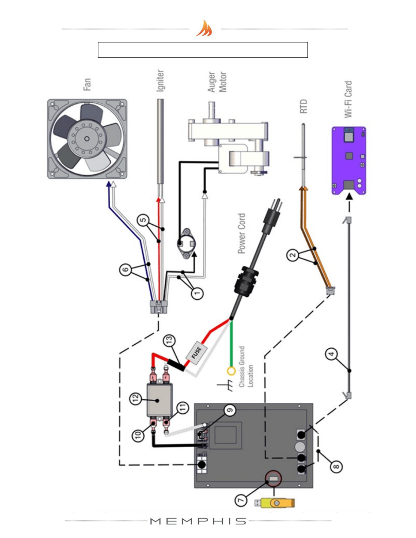
Memphis Control Diagram
NOTE: ALL TWO
-WIRE PAIRS FOR A SPECIFIC COMPONENT ARE REVERSIBLE.
Example: The auger motor wiring can have either spade connector from its two
-wire pair
attached to a terminal, and the motor will function normally.
12
Item # NAME Wire Idencaon
DESCRIPTION / INSTRUCTION
1
Auger Motor
Wiring
1x Black Wire, 1x White Wire
Snap Disk
Leads Extending from Auger
Motor
Aach the white wire shown to one of the leads extending from the
auger motor. Aach the black wire to the snap disk as shown. The
2
nd
lead extending from the auger motor aaches to the opposite
side of the snap disk as shown. The snap disk is a thermal switch
which will cut power to the auger motor in the event that its crical
temperature is reached.
2 RTD Wiring 1x Orange Wire, 1x Brown Wire
Aach both spade connectors to the leads extending from the RTD
as shown above.
3 Grounding Wire Green Wire
The connecon point for the ground is located on the auger motor
gearbox body as shown.
4 Ethernet Cable Black Cable with Ethernet End
Aach the Ethernet cable to the terminal on the Wi-Fi card as
shown. Ensure that the wiring does not interfere with the auger
motor’s moving components.
5 Igniter Wiring 1x Red Wire, 1x White Wire
Aach both spade connectors to the leads extending from the
igniter. These leads will extend from next to the fan.
6 Fan Wiring
1x Blue Wire w/ 2 spade ends,
1x White Wire w/ 2 spade ends
Aach the connecons on this jumper to the two tabs located on
the side of the fan housing.
7 USB Port N/A
Used to update your grill.
8
Meat Probe
Wiring
1x Red Wire 1x Black Wire,
Wires twisted around each
other
This terminal is used to connect the meat probes to the controller.
9
120/240 Select
Jumper
1x Black Wire
Used when changing the input voltage to the controller, see “120v
to 240v Conversion” secon of the main manual for informaon.
10
AC Load Wire
from Filter to
Controller
1x Black Wire
Carries AC voltage from the lter to the control board, load wire.
11
AC Neutral Wire
from Filter to
Controller
1x White Wire
Carries AC voltage from the lter to the control board, neutral wire.
12 Filter N/A
Reduces electrical feedback. Line = Outlet Side, Load = Grill Side. L1
= Load L2= Neutral
13
MOV + Fuse
Holder
1x Red Wire 1x White Wire.
Pair is joined in the middle with
black shrink wrap. Fuse holder is
cylindrical and white plasc.
A two-wire component, which has a ferrite choke to eliminate input
electrical disturbances from the grid, connects to Load and Neutral
terminals. Fuse holder accepts a 5 amp glass fuse.
CONTACT YOUR DEALER OR MEMPHIS GRILLS TECHNICAL SERVICE WITH ANY QUESTIONS.
TECHNICAL SERVICE NUMBER: 1-888-883-2260
Memphis Control Diagram continued
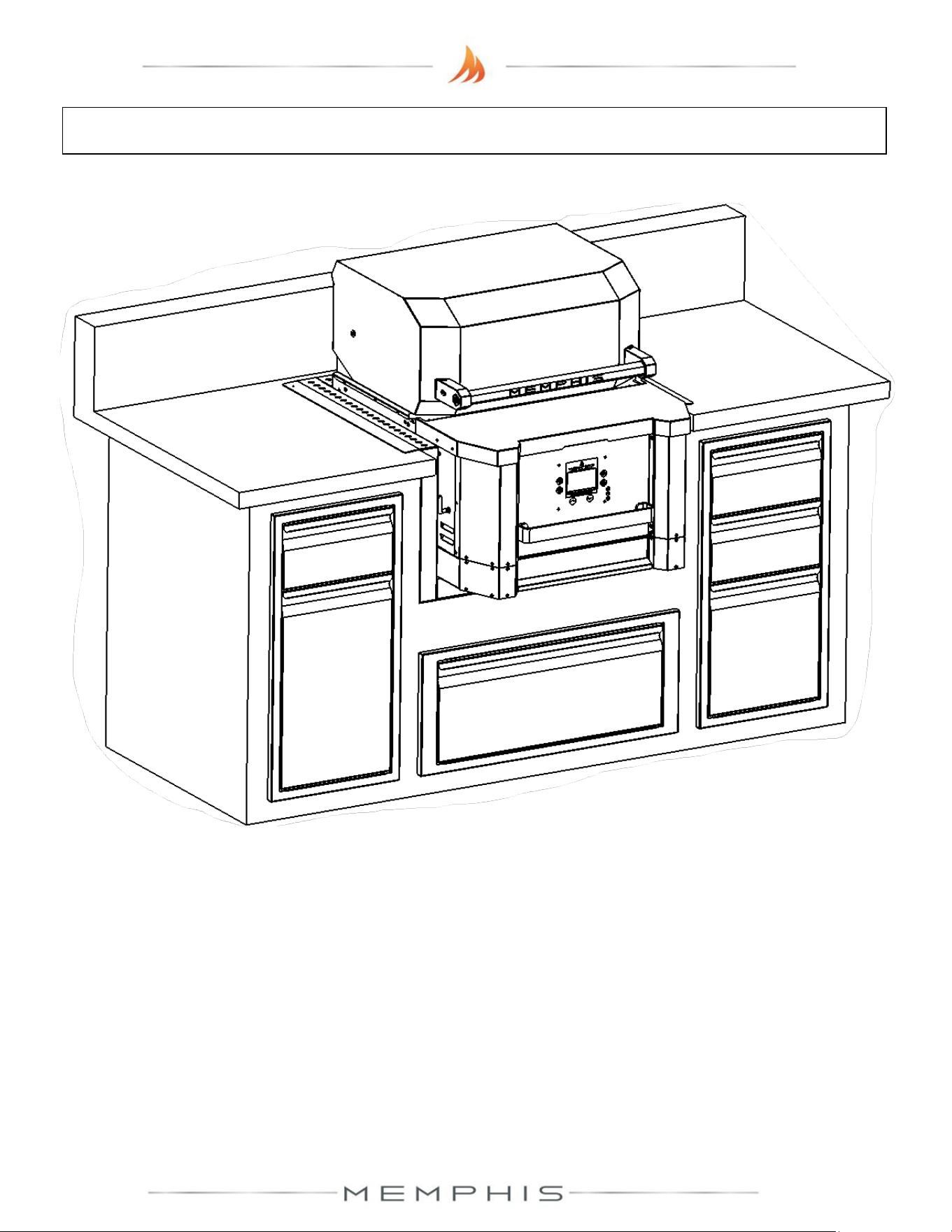
13
MODEL NUMBER: MG11-06-001
Built-in Brackets Assembly
1. Cutout Dimensions
2. Dimensions
3. Parts List
4. Assembly Instructions
14
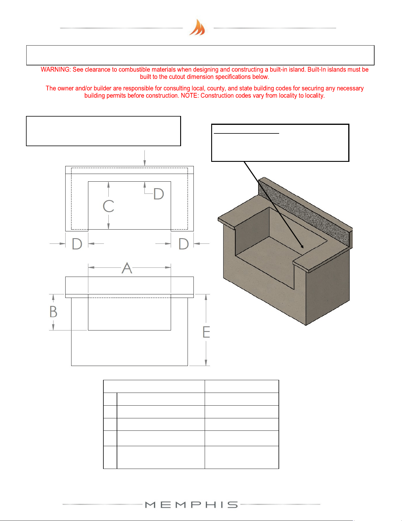
Built-In Cutout Dimensions
CUTOUT DIMENSIONS TOLERANCE
A 30 1/4” [76.9 cm] +/- 1/8” [0.30 cm]
B 16 3/4” [42.6 cm] +/- 1/8” [0.30 cm]
C 24 1/2” [62.9 cm] +/- 1/8” [0.30 cm]
D 3 1/2” MIN [8.9 cm] -
E Standard Cabinet
Height
-
NOTE: Dimensions are to the finished surfaces.
Grill cavity surfaces are to be plumb and level
to ensure a proper fit.
Power Requirements
110/120VAC* supply required within 10 feet
of the ITC.
Top View
Front View
15
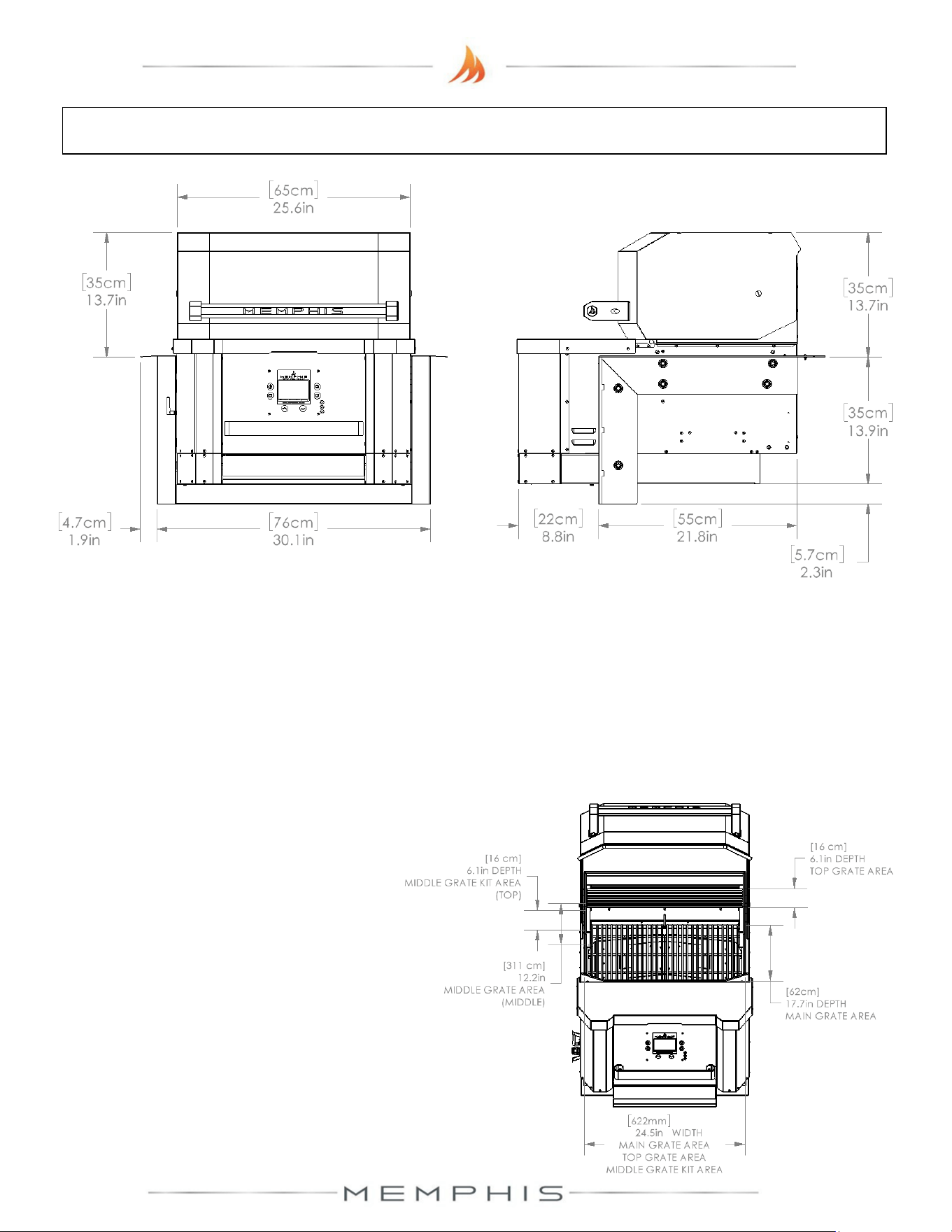
Built-in Bracket Dimensions
Additional Grill Dimensions
Main Grate Area– 24.5 in X 17.7 in [62 cm X 45 cm] 428 in
2
[2,761 cm
2
]
Top Grate Area– 24.5 in X 6.125 in [63 cm X 16 cm] 150 in
2
[968 cm
2
]
*Middle Grate Kit Area– 3 x 24.5 in X 6.125 in [3 x 63 cm X 16 cm] 501 in
2
[3,232 cm
2
]
* - Item sold separately
Grill Height with Hood Open– 40.0 in [102 cm]
16
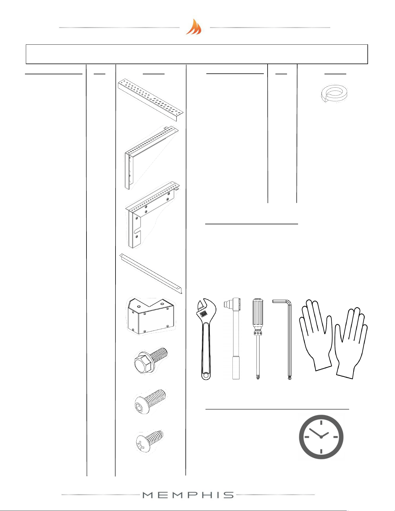
Built-In Brackets Parts List
Description/ Part No. Qty: Picture:
Description/ Part No.
Qty: Picture:
2. Right Mounting
Bracket
MA01-00013
1
3. Left Mounting
Bracket
MA01-00014
1
7. M6 Screw (SS
MH01-00021
6
8. #10 Screw (SS)
DS2186
2
4. Lower Mounting
Bracket
MD01-00041
1
1. Rear Mounting
Bracket BG8001
1
6. M6 Screw (SS)
MH01-00015
12
5. Front Lower Cap
MA09-00022
1
9. M6 Lock Washer
MH02-00002
6
TOOLS REQUIRED
• 10mm Open-end Wrench, Socket or
Adjustable Wrench
• Phillips Screwdriver or Drill
• 4mm Allen Wrench
• Cut-Resistant Gloves
ESTIMATED TIME REQUIRED
0.75 Hours
(excludes removal
of protective film)
17
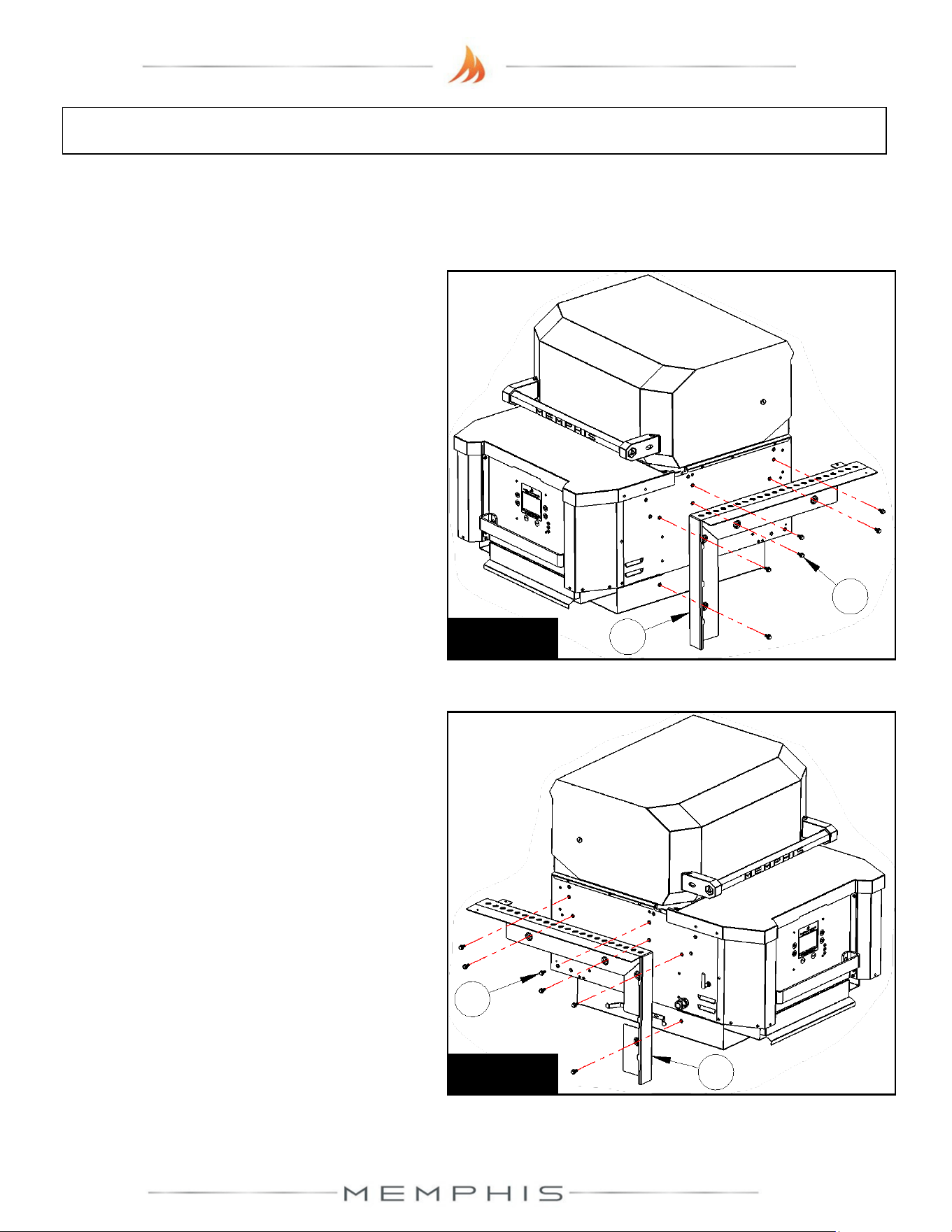
Built-In Brackets: Assembly Instructions
Peel all plastic protective film off prior to performing the assembly steps listed below. Refer
to page 16 for item part numbers, descriptions, and quantities.
Step 2) Attach left mounting bracket (Part 3)
onto the left side of the grill using 6 screws
(Part 6) (See Figure 2).
Step 1) Attach right mounting bracket (Part
2) onto the right side of the grill using 6
screws (Part 6) (See Figure 1).
Figure 2
6
3
Figure 1
6
2
18
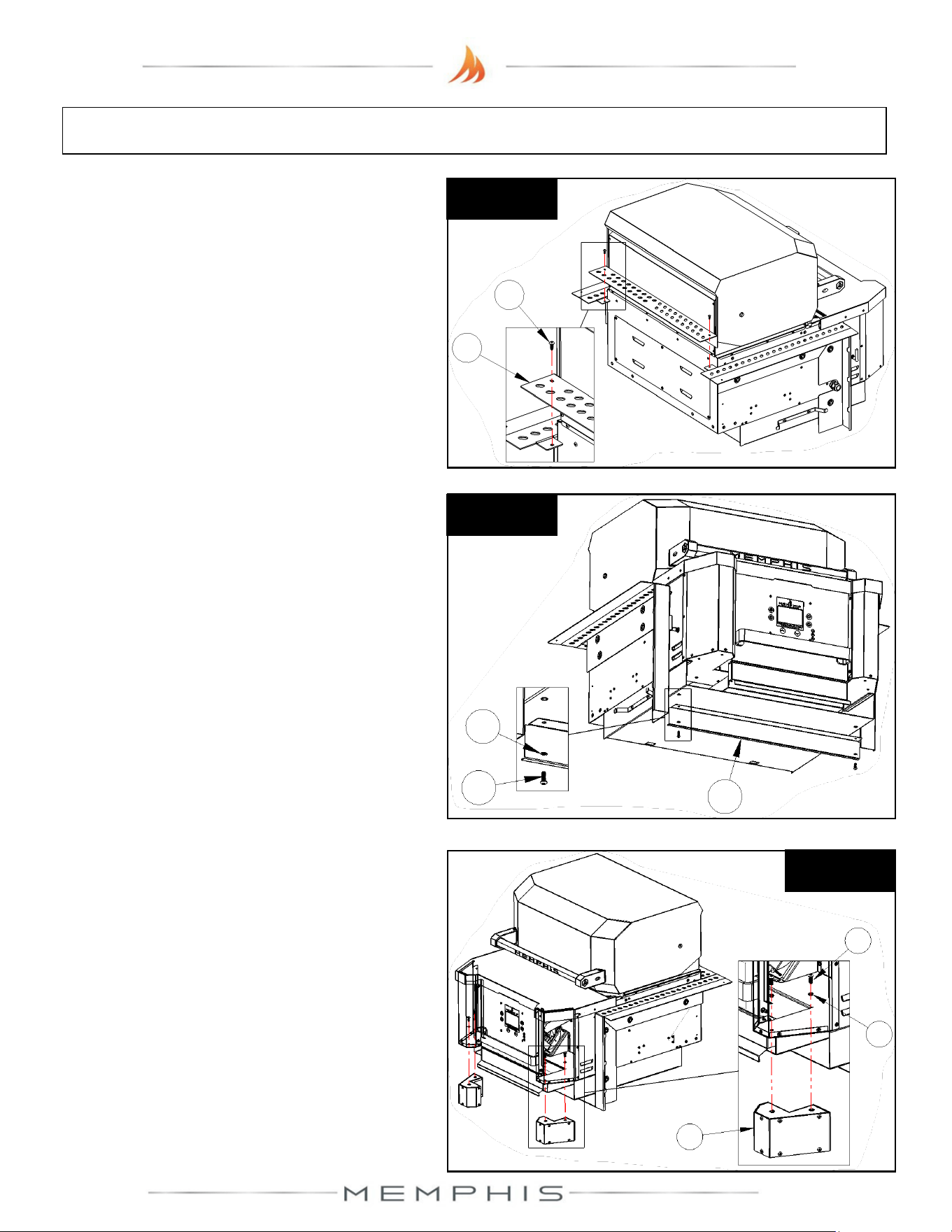
Built-In Brackets: Assembly Instructions
Step 4) Attach lower mounting bracket (Part
4) onto the bottom of the grill using 2 screws
(Part 7) and 2 washers (Part 9) (See Figure
4).
Step 3) Attach rear mounting bracket (Part 1)
onto the side brackets using 2 screws (Part
8) (See Figure 3).
Figure 3
8
1
Figure 4
9
7
4
Step 5) Attach front lower caps (Part 5) onto
the bottom corners of the grill using 4 screws
(Part 7) and 4 washers (Part 9) (See Figure
5).
Figure 5
5
9
7
19
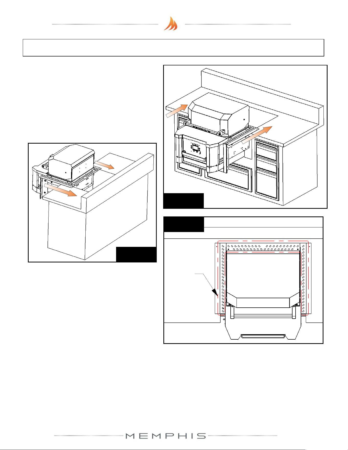
Built-In Brackets: Assembly Instructions
Step 6) With two people, lift the grill onto the
island countertop and slide into the island
cutout (See Figures 6a & 6b). Ensure vent
holes on mounting brackets remain
unobstructed for proper air circulation (See
Figure 6c).
Figure 6b
Figure 6a
Figure 6c
Vent
holes
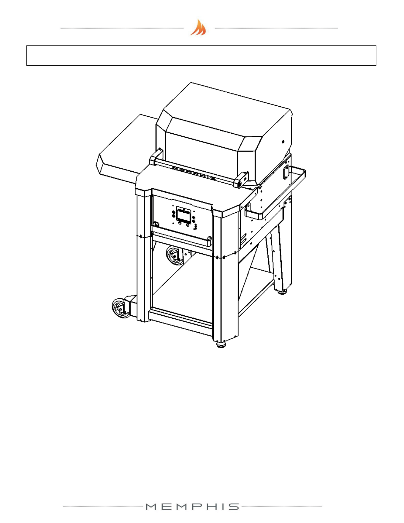
20
MODEL NUMBER: MG11-06-002
Leg Assembly
1. Dimensions
2. Parts List
3. Assembly Instructions
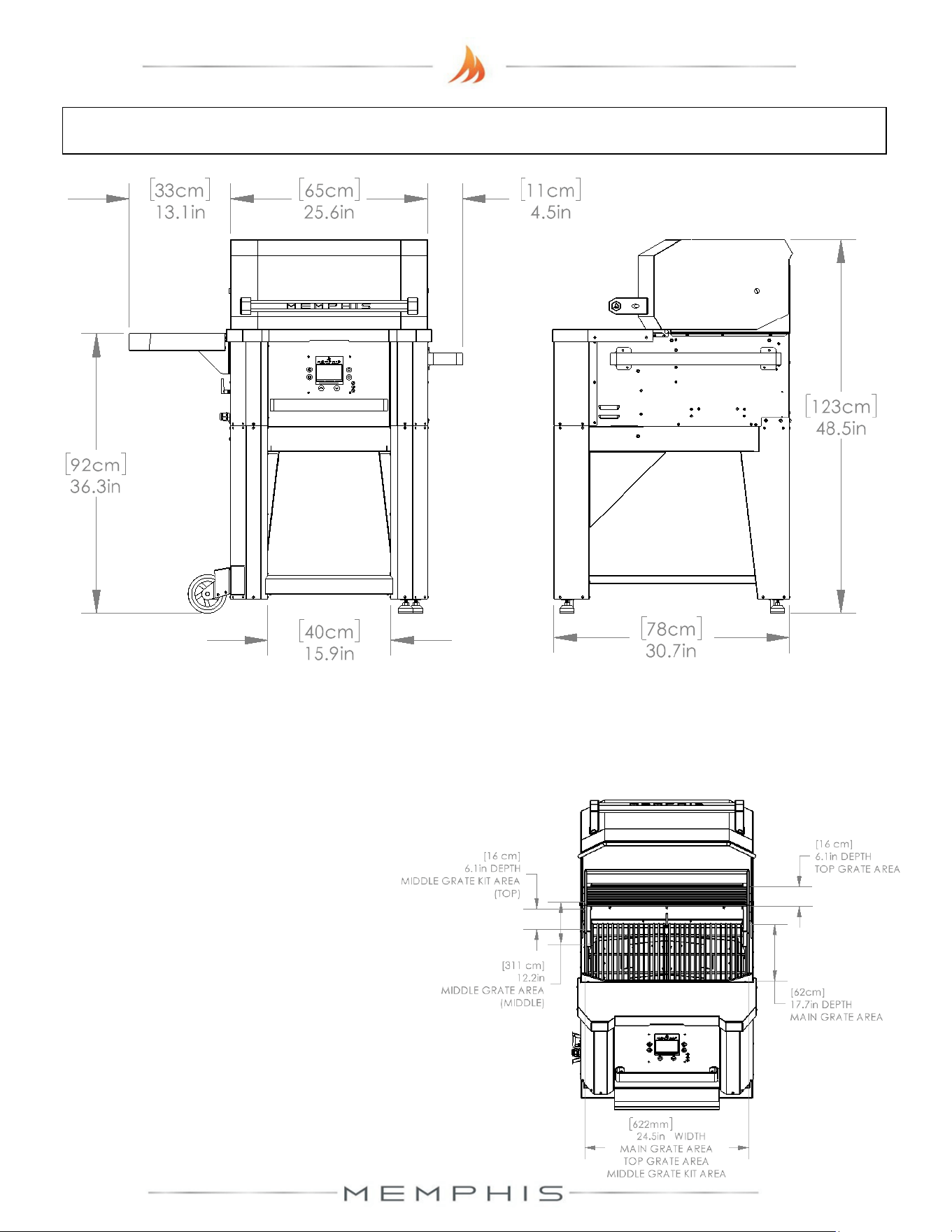
21
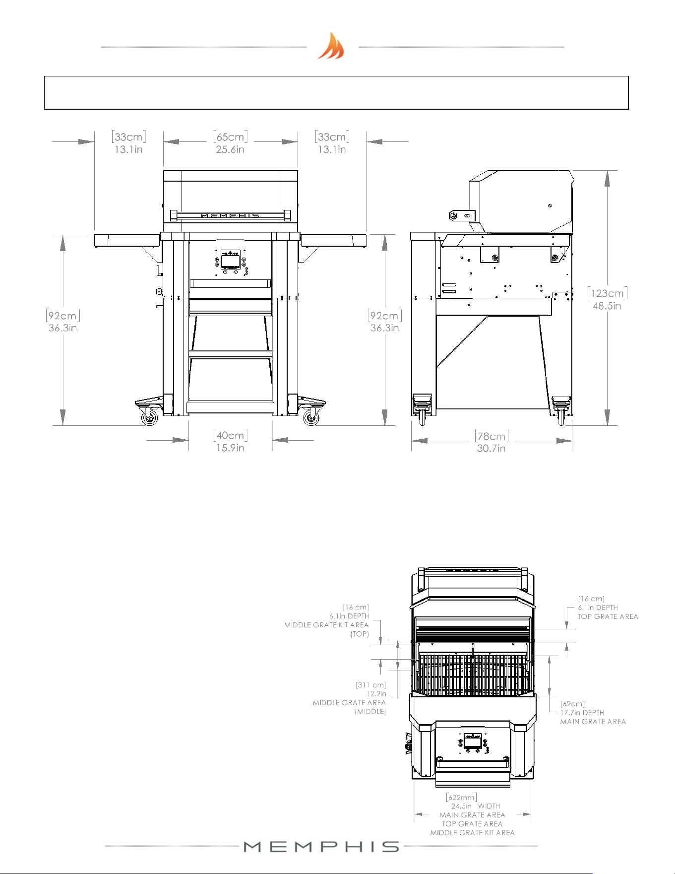
Leg Assembly Dimensions
Additional Grill Dimensions
Main Grate Area– 24.5 in X 17.7 in [62 cm X 45 cm] 428 in
2
[2,761 cm
2
]
Top Grate Area– 24.5 in X 6.125 in [63 cm X 16 cm] 150 in
2
[968 cm
2
]
*Middle Grate Kit Area– 3 x 24.5 in X 6.125 in [3 x 63 cm X 16 cm] 501 in
2
[3,232 cm
2
]
* - Item sold separately
Grill Height with Hood Open– 60.9 in [155 cm]
22
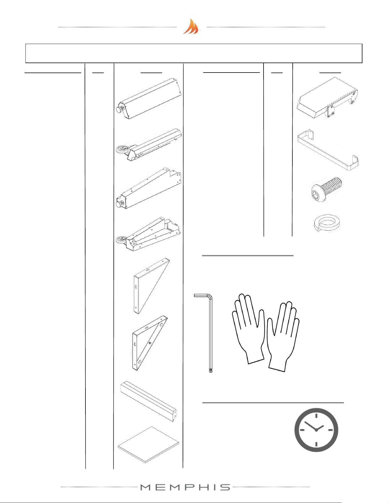
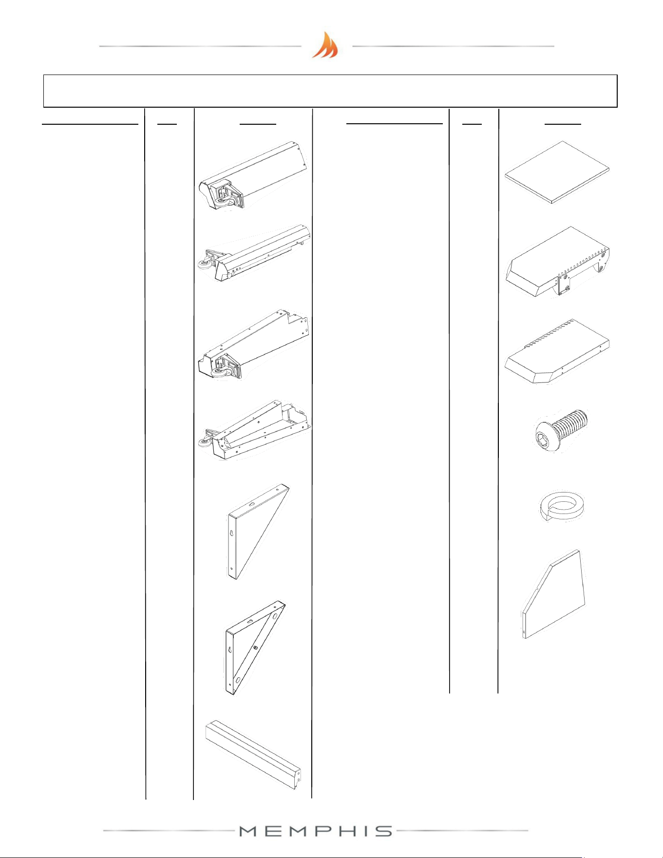
Leg Assembly Parts List
Description/ Part No. Qty: Picture:
Description/ Part No.
Qty: Picture:
1. Front Right Leg
MA09-00013
1
2. Front Left Leg
MA09-00023
1
3. Rear Right Leg
MA09-00015
1
4. Rear Left Leg
MA09-00024
1
7. Bottom Cross
Brace
MA09-00005
1
8. Lower Shelf
MA06-00003
1
9. Left Side Shelf
MA06-00011
1
10. Grill Side Handle
MD01-00035
1
11. M6 Screw (SS
MH01-00021
36
12. M6 Lock Washer
MH02-00002
36
TOOLS REQUIRED
• 4mm Allen Wrench
• Cut-Resistant Gloves
6. Front Left Leg
Brace
MA09-00030
1
5. Front Right Leg
Brace
MA09-00020
1
ESTIMATED TIME REQUIRED
1.50 Hours
(excludes removal
of protective film)
23
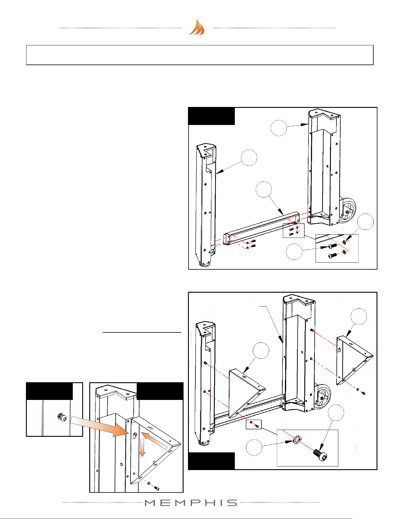
Leg Assembly: Assembly Instructions
Peel all plastic protective film off prior to performing the assembly steps listed below. Refer
to page 22 for item part numbers, descriptions, and quantities.
Step 2) Attach front leg braces (Part 5 & Part
6) onto the front legs from Step 1 using 4
screws (Part 11) and 4 lock washers (Part
12) (See Figure 2a). Partially thread screws
with lock washers onto the top holes, and
then insert and position the leg braces before
tightening (See Figures 2b & 2c).
Step 1) Attach bottom cross brace (Part 7) to
front right leg (Part 1) and front left leg (Part
2) using 4 screws (Part 11) and 4 lock
washers (Part 12) (See Figure 1).
Figure 1
2
1
7
11
12
12
Figure 2a
6
5
11
From Step 1
Figure 2c
Figure 2b
24
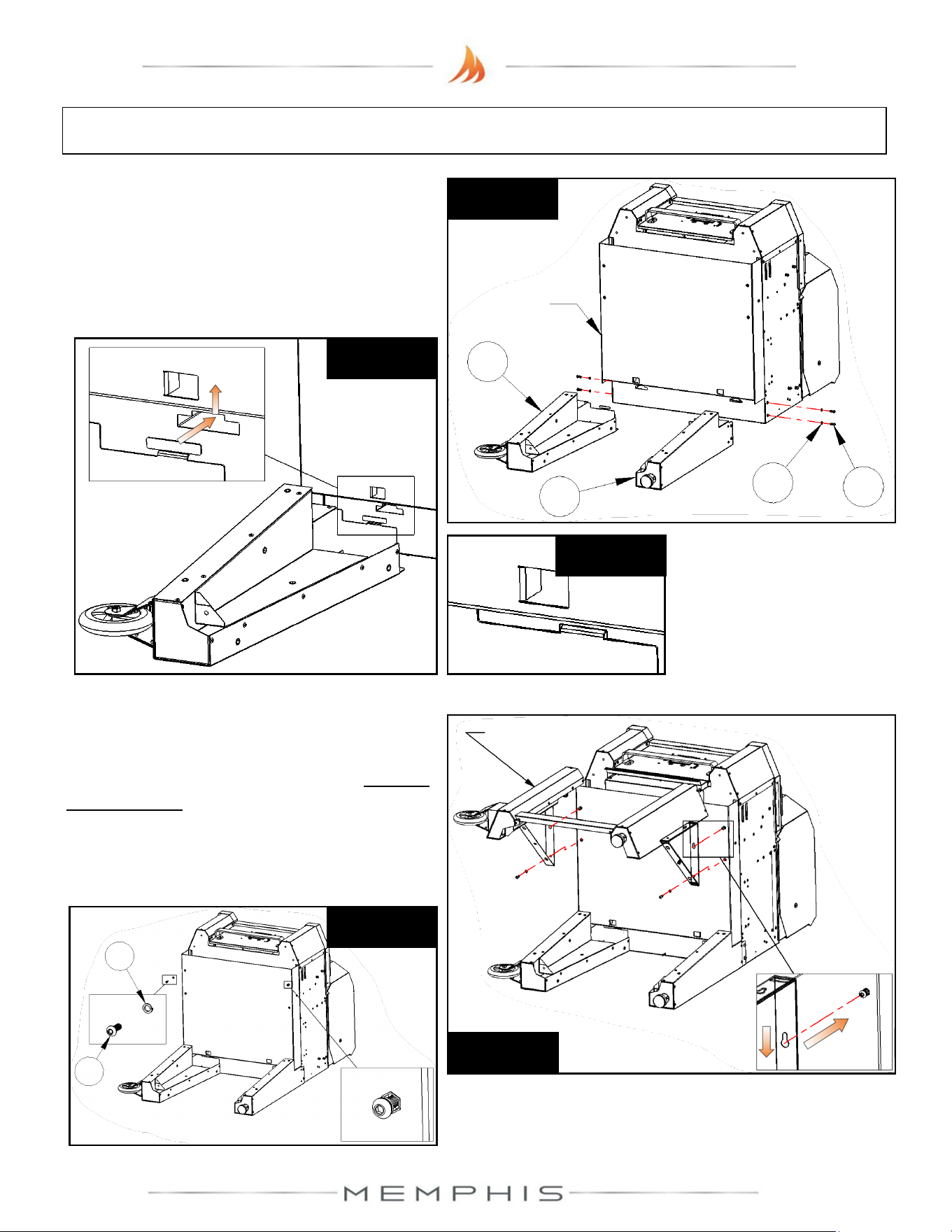
Leg Assembly: Assembly Instructions
Step 3) Lay grill on its back. Attach rear legs
(Part 3 & Part 4) onto the grill using 4 screws
(Part 11) and 4 lock washers (Part 12) (See
Figure 3a). Slide and set the tab into the slot
(See Figures 3b & 3c) before threading on
the screws with lock washers.
Figure 3a
3
4
11
12
Grill
Figure 3c
Figure 3b
Step 4) Attach the front leg assembly from
Step 2 using 4 screws (Part 11) and 4 lock
washers (Part 12) (See Figure 4a). Partially
thread screws with lock washers onto the top
holes, and then insert and position the leg
braces before tightening (See Figure 4b).
From Step 2
Figure 4a
Applies to
both sides
Figure 4b
12
11
25
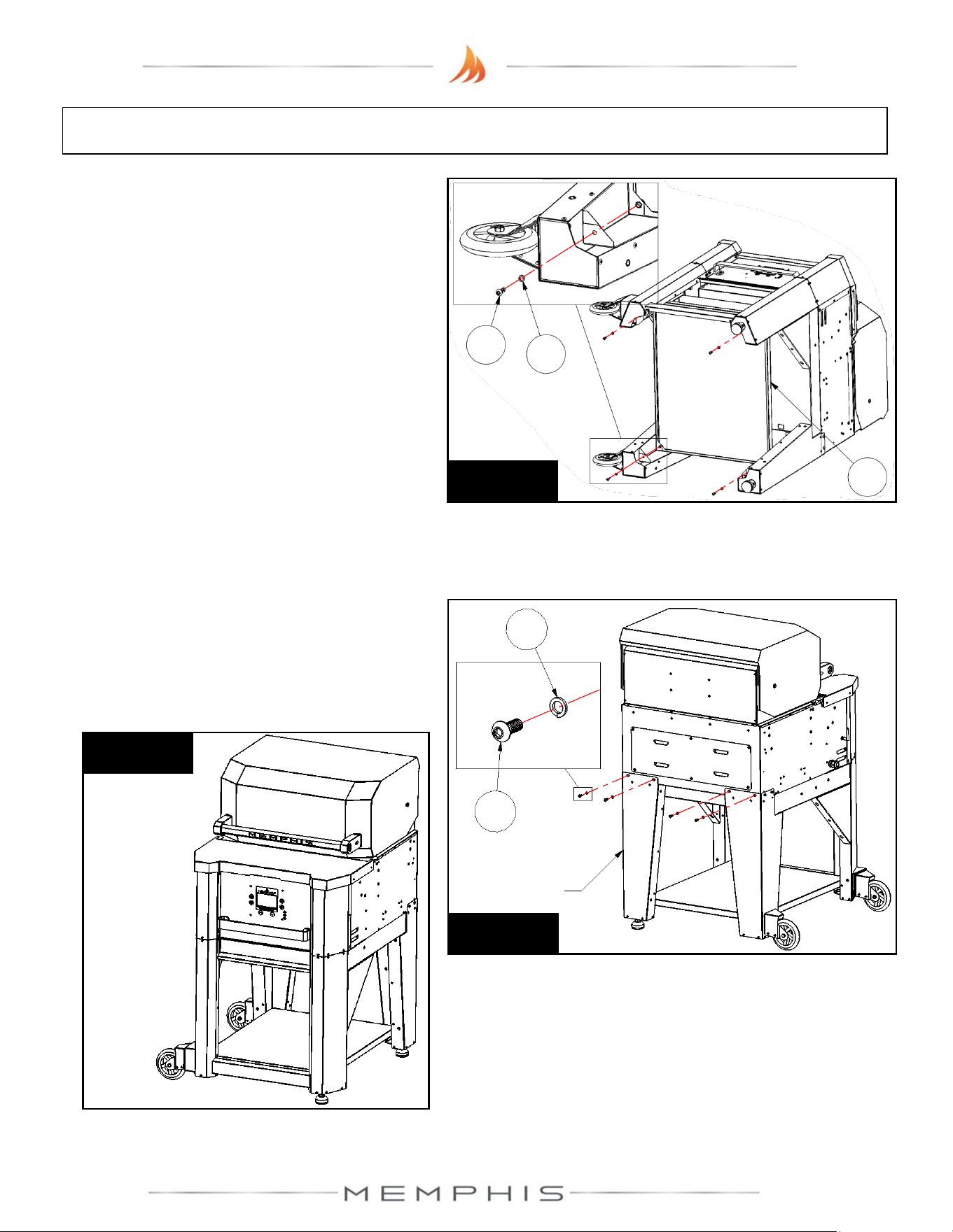
Leg Assembly: Assembly Instructions
Step 5) Attach lower shelf (Part 8) onto the
leg assembly using 4 screws (Part 11) and 4
lock washers (Part 12) (See Figure 5).
Figure 5
11
12
8
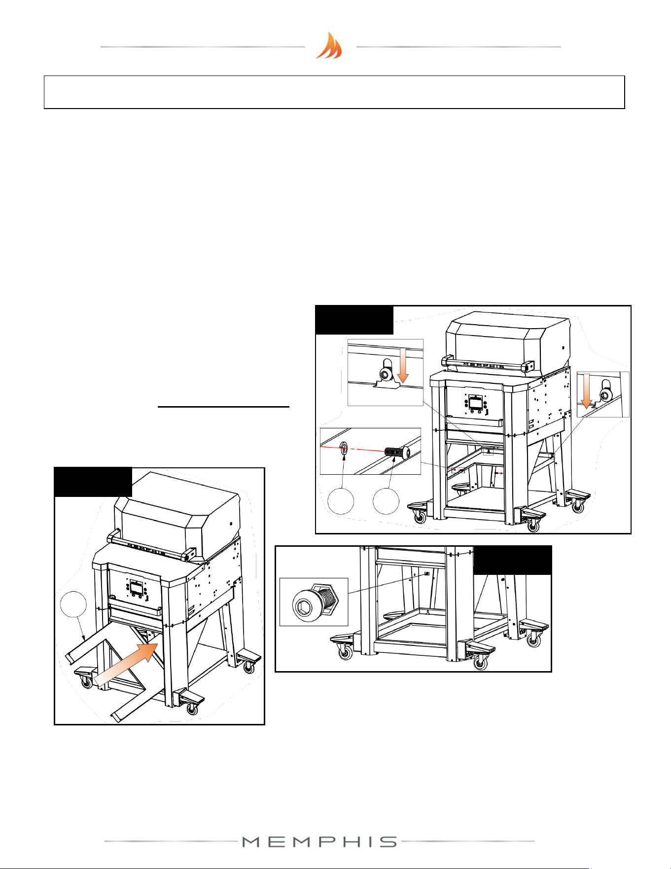
Step 6) With two people, lift grill into the
upright position (See Figure 6b). From the
rear of the grill, attach the leg assembly onto
the grill using 4 screws (Part 11) and 4 lock
washers (Part 12) (See Figure 6a).
Figure 6a
12
11
Leg
Assembly
Figure 6b
26
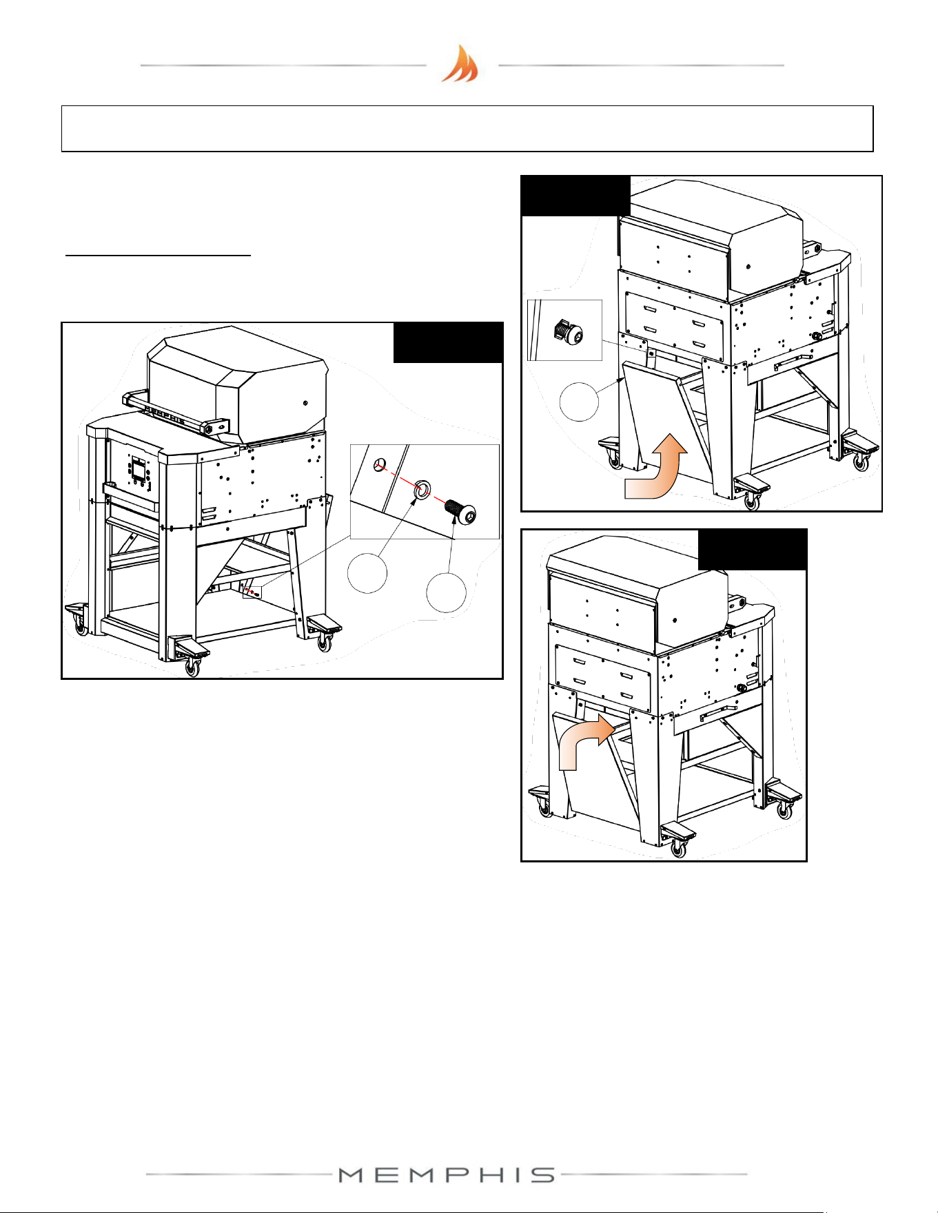
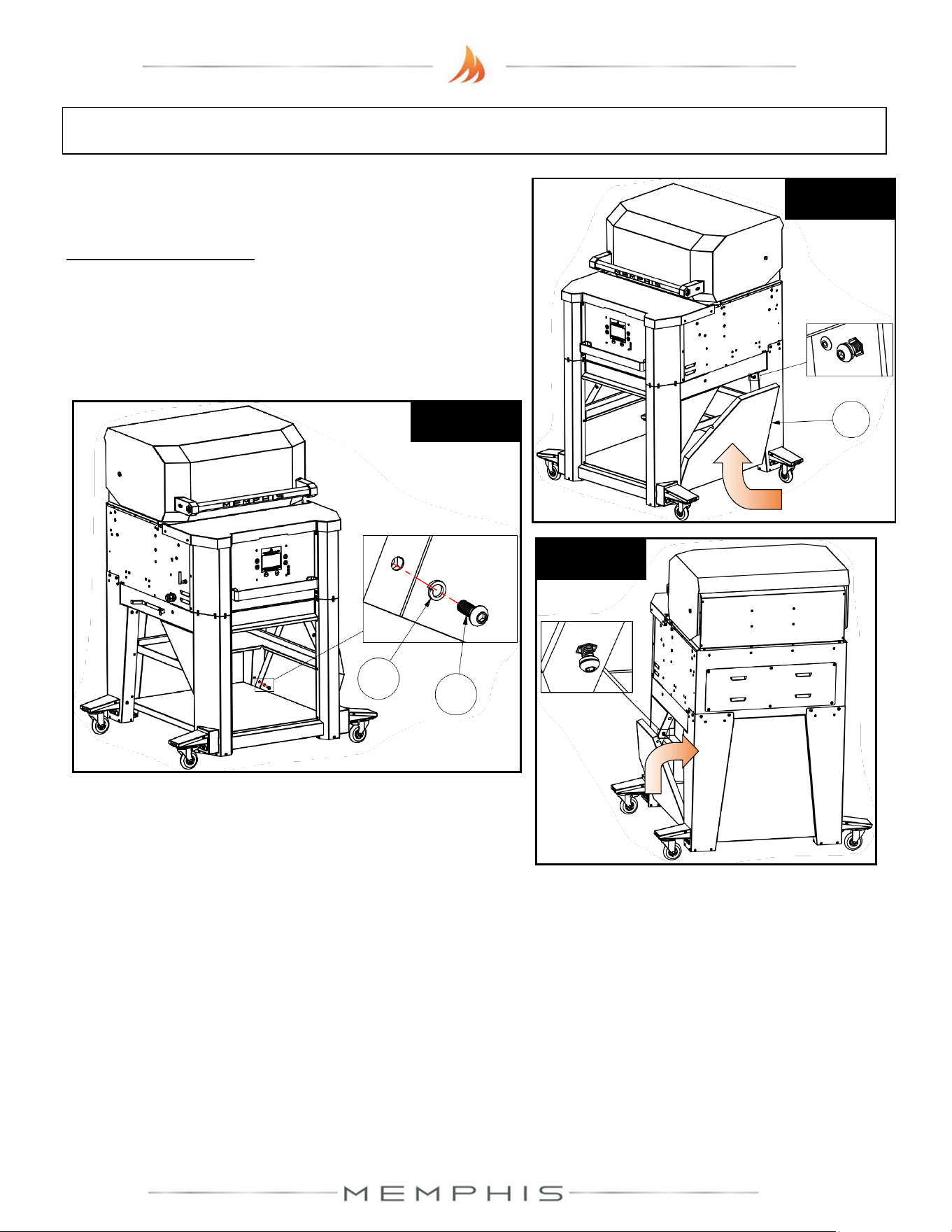
Leg Assembly: Assembly Instructions
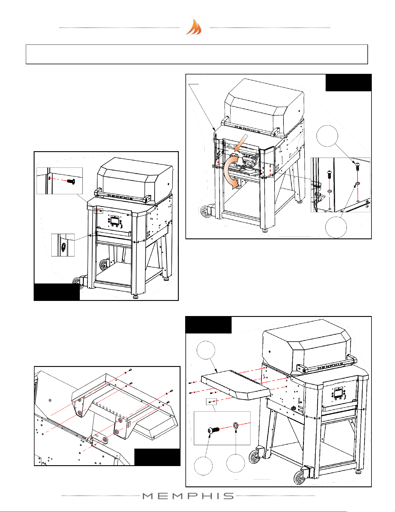
Step 7) Loosen the bottom two screws and
remove the top two screws from the front
panel (See Figure 7b). Slide the hopper lid
forward, and lift and rotate the front panel
forward to access the interior. Attach the grill
to the legs using 4 screws (Part 11) and 4
lock washers (Part 12) (See Figure 7a).
Figure 7b
Applies to
both sides
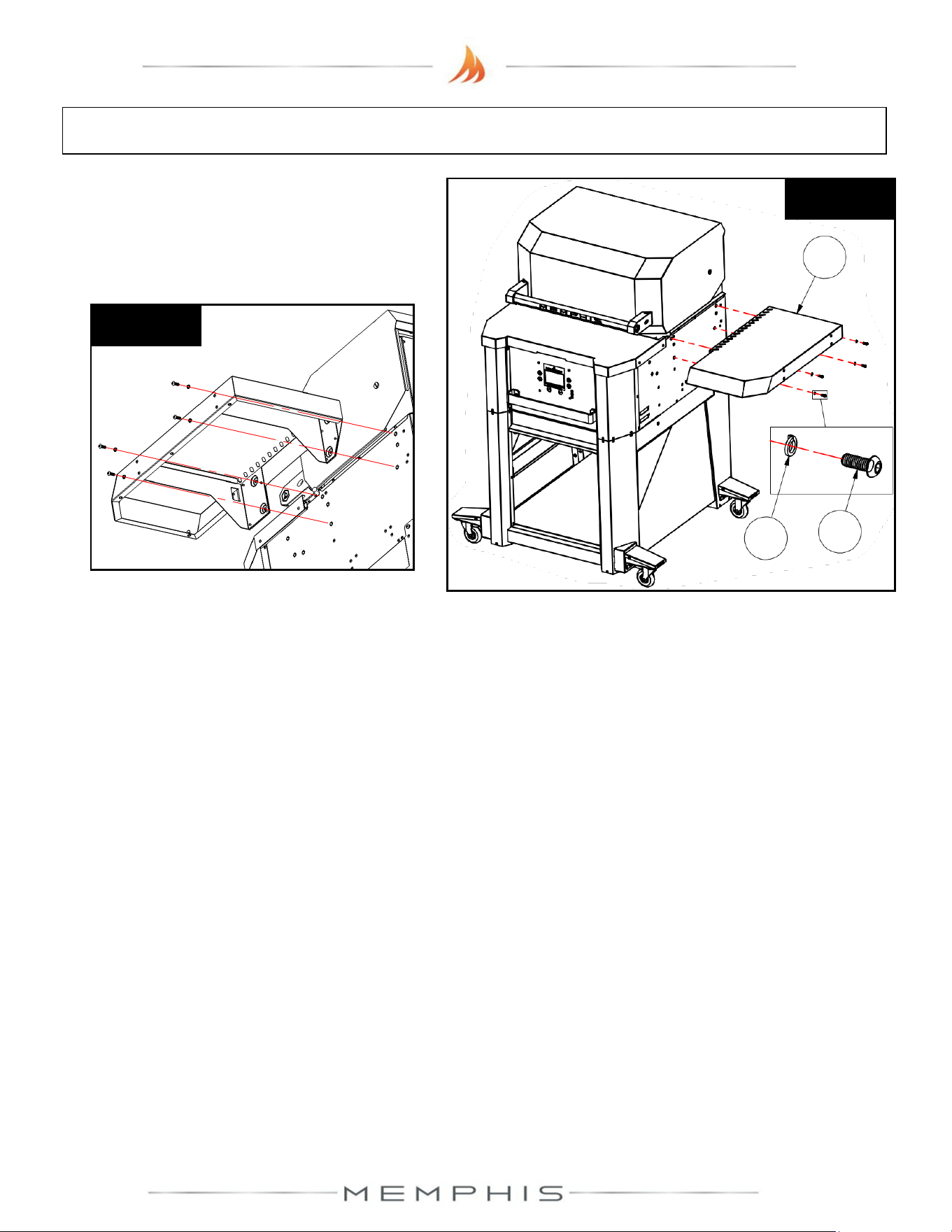
Step 8) Attach left side shelf (Part 9) onto the
left side of the grill using 4 screws (Part 11)
and 4 lock washers (Part 12) (See Figure 8a
& 8b).
Figure 8a
11
12
9
Figure 8b
Applies to
both sides
Figure 7a
11
12
Hopper
Lid
27
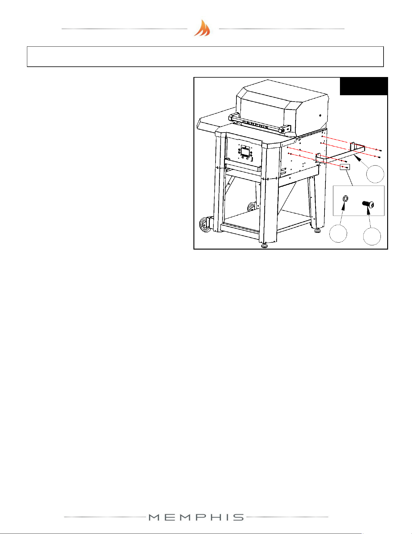
Step 9) Attach grill side handle (Part 10) onto
the right side of the grill using 4 screws (Part
11) and 4 lock washers (Part 12) (See
Leg Assembly: Assembly Instructions
Figure 9
11
12
10
28
MODEL NUMBER: MG11-06-003
Surround Assembly
1. Dimensions
2. Parts List
3. Assembly Instructions
29
Surround Assembly Dimensions
Additional Grill Dimensions
Main Grate Area– 24.5 in X 17.7 in [62 cm X 45 cm] 428 in
2
[2,761 cm
2
]
Top Grate Area– 24.5 in X 6.125 in [63 cm X 16 cm] 150 in
2
[968 cm
2
]
*Middle Grate Kit Area– 3 x 24.5 in X 6.125 in [3 x 63 cm X 16 cm] 501 in
2
[3,232 cm
2
]
* - Item sold separately
Grill Height with Hood Open– 60.9 in [155 cm]
30
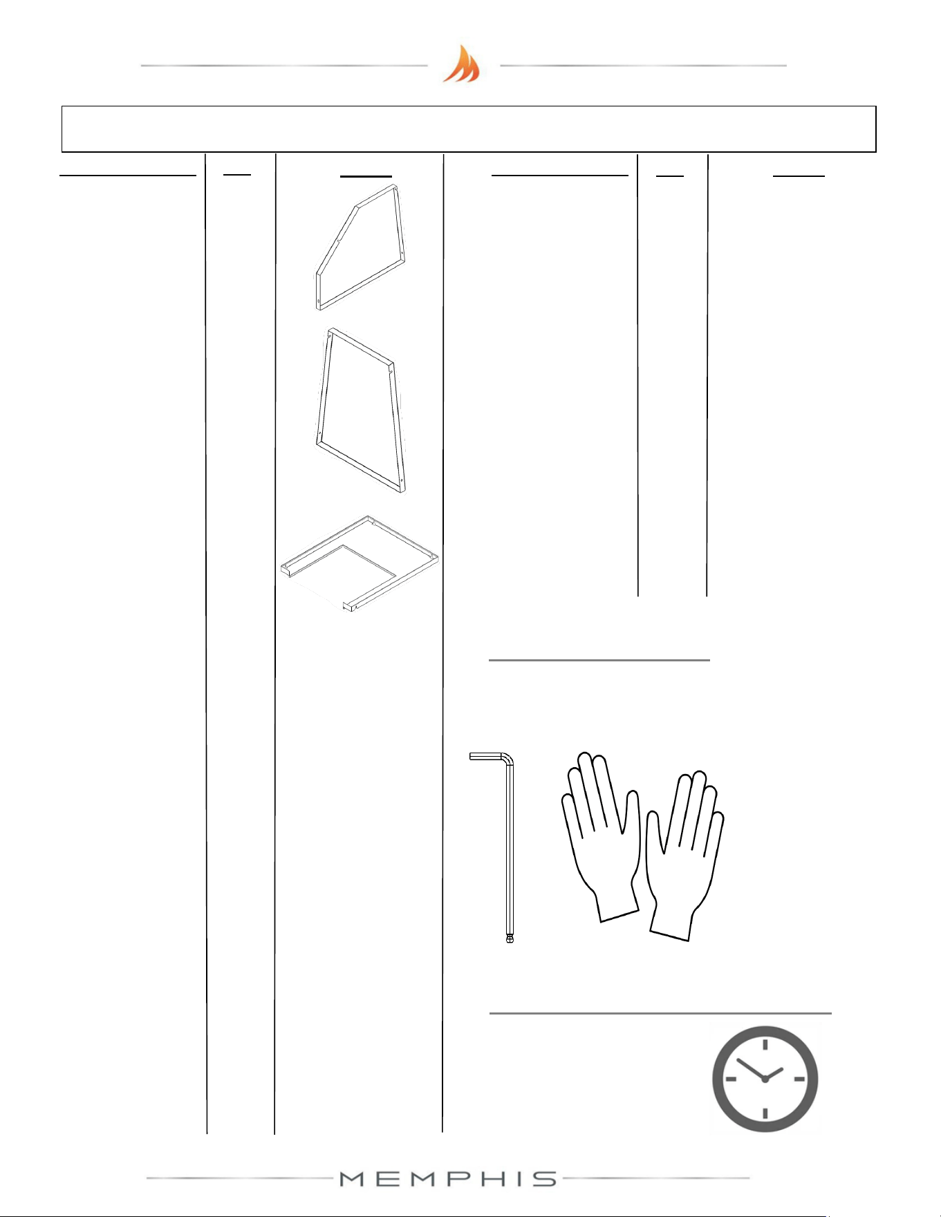
Surround Assembly Parts List
Description/ Part No. Qty: Picture:
Description/ Part No.
Qty: Picture:
10. Side Shelf Right
MA06-00012
1
13. Right Panel
MD09-00045
1
1. Front Leg Right
MA09-00018
1
2. Front Leg Left
MA09-00028
1
3. Rear Leg Right
MA09-00019
1
4. Rear Leg Left
MA09-00029
1
7. Bottom Cross
Brace
MA09-00005
1
6. Front Leg Brace
Left
MA09-00030
1
5. Front Leg Brace
Right
MA09-00020
1
9. Side Shelf Left
MA06-00011
1
8. Lower Shelf
MA06-00003
1
11. M6 Screw (SS
MH01-00021
52
12. M6 Lock Washer
MH02-00002
52
Parts List Continued…...
31
Surround Assembly Parts List continue
Description/ Part No.
Qty:
Picture:
Description/ Part No.
Qty: Picture:
TOOLS REQUIRED
• 4mm Allen Wrench
• Cut Resistant Gloves
ESTIMATED TIME REQUIRED
2.00 Hours
(excludes removal
of protective film)
16. Middle Shelf
MD06-00006 1
14. Left Panel
MD09-00046
1
15. Rear Panel
MD09-00047
1
32
Surround Assembly: Assembly Instructions
Peel all plastic protective film off prior to performing the assembly steps listed below. Refer
to page 30-31 for item part numbers, descriptions, and quantities.
Step 1) Turn to the Leg Assembly: Assembly Instructions section (pages 23 to 26) and complete
assembly instructions step 1 to step 7.
Step 2) Attach middle shelf onto the leg
assembly using 4 screws (Part 11) and 4 lock
washers (Part 12) (See Figure 2a). First,
slide the middle shelf (Part 16) into the leg
assembly and lay it on the bottom shelf (See
Figures 2b & 2c). Partially thread screws
with lock washers at the rear locations (See
Figure 2c), and then position the middle
shelf before tightening.
Figure 2b
16
Figure 2c
Applies to
both sides
Figure 2a
12
11
33
Surround Assembly: Assembly Instructions
Step 3) Attach rear panel (Part 15) using 4 screws
(Part 11) and 4 lock washers (Part 12).
Partially thread screws with lock washers at the top
rear locations, and then slide rear panel (Part 15) onto
the rear opening of the leg assembly (See Figure 3a).
Figure 3b
12
11
15
Figure 3a
Applies to
both sides
Figure 3c
Attach the screws with lock washers at the bottom
locations (See Figure 3b). Fold the rear panel upward
before tightening the screws (See Figure 3c).
34
Surround Assembly: Assembly Instructions
Step 4) Attach right panel (Part 13) using 4 screws
(Part 11) and 4 lock washers (Part 12).
Partially thread screws with lock washers at the top
side locations, and then slide right panel (Part 13) onto
the side opening of the leg assembly (See Figure 4a).
Attach the screws with lock washers at the bottom
locations, and then fold the right panel upward before
tightening the screws (See Figure 4b & 4c).
Figure 4b
12
11
13
Figure 4a
Figure 4c
Step 5) Attach left panel (Part 14) using 4 screws (Part 11) and 4 lock washers (Part 12). Follow
Step 4, but this time for the left hand side.
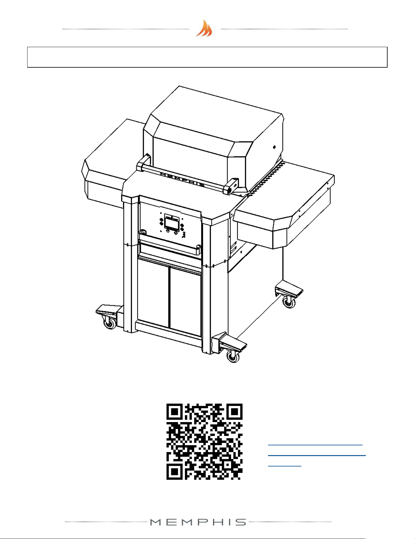
35
Surround Assembly: Assembly Instructions
Step 6) Attach right side shelf (Part 10) onto
the right side of the grill using 4 screws (Part
11) and 4 lock washers (Part 12) (See
Figure 6a & 6b).
Figure 6a
12
11
10
Figure 6b
Step 7) Attach left side shelf (Part 9) using 4 screws (Part 11) and 4 lock washers (Part 12).
Follow Step 6, but this time for the left hand side.

37
Attention!
To access the latest Product Manuals,
scan the QR Code above.
Or visit our website at:
https://memphisgrills.com/support-resources/support-manuals/
Scan to access
Product Manuals