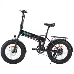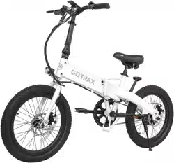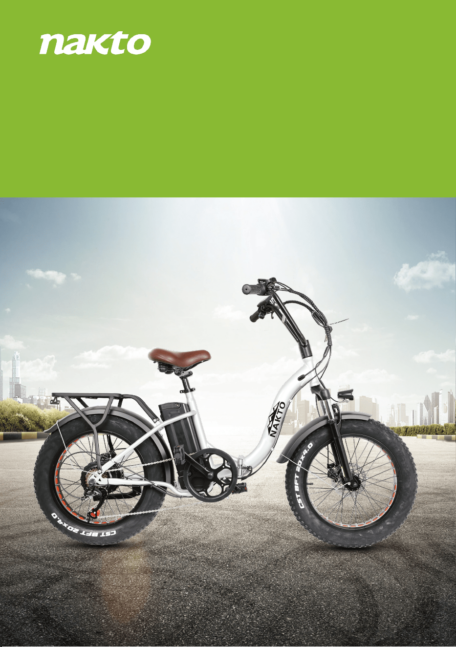
Folding OX
Fully Assembled Folding OX Black and Folding OX Silver.
Folding OX Black
Folding OX Silver
Let’s start assembling your NAKTO Folding OX ebike!
(Please read this entire assembly manual before assembly as it will save
you a lot of time!)
Step One.
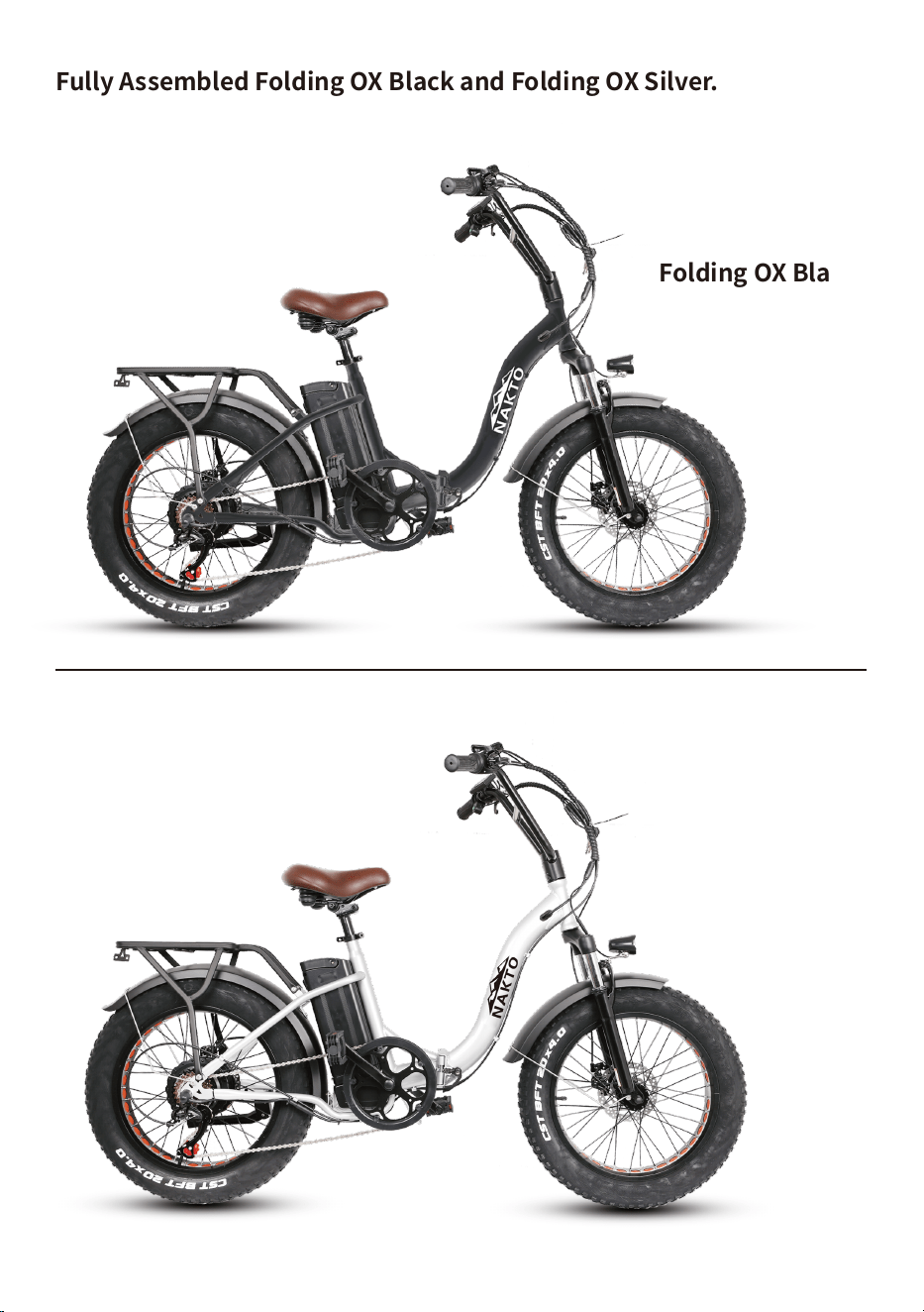
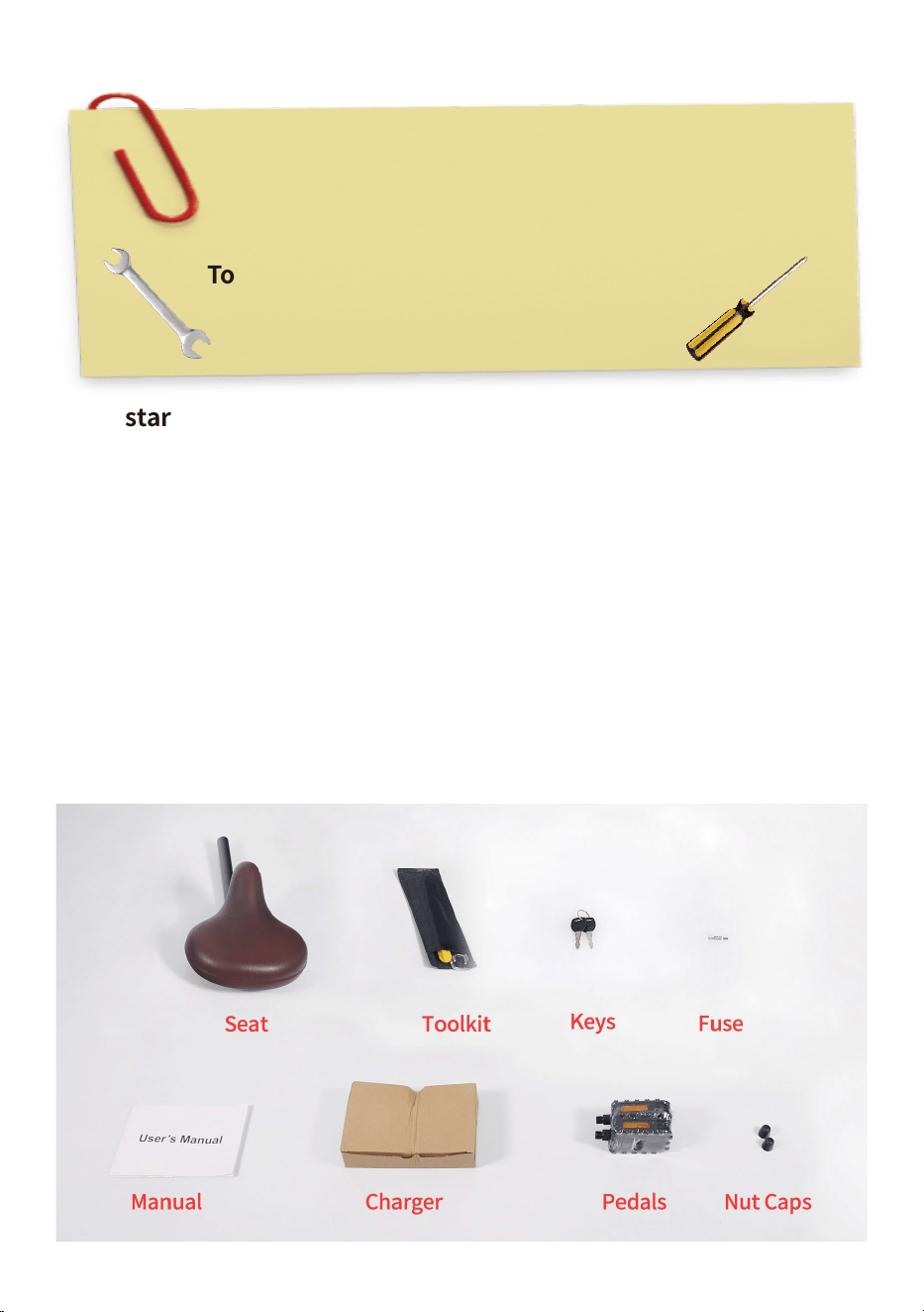
1.Unpack the bike. Pull the frame and all parts ( seat, manual, charger,
pedals, nut caps, keys, fuse and toolkit) out of cardboard box. Separate
bike from foam padding. Cut off all zip ties with scissors while being extra
careful as not to damage the paint or cut any wires or cables.Notice:
Keep the spare fuse in a safe place.It is not used for assembly and will be
used for the replacement if the original fuse were damaged.
Ensure all the following pieces are included with the Nakto Folding
OX.
Assembly Instructions: Folding OX
Tools included: Screwdriver, Phillips & Slotted 2 in 1
Double open-end wrench, 13mm/15mm
Allen wrench, 5mm
Tools needed: Scissor
Bike pump
2.Now stand the bike upright. Place some foam padding under the front
fork if placed on the ground or put it on bike assembly/repair stand if you
have one. We want to keep your bike looking new!
Step Two: Assemble the front wheel.
1.Loosen axle nuts on front wheel to make room for the front fork.
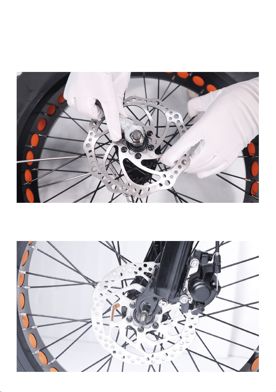
2.Lift the front of the bike and lower the fork onto the wheel axle. Notice:
The brake rotor should go into the brake caliper in between the brake
pads and the axle should enter the fork dropouts fully. The front rotor
orientation should be to the left of the fork.
3.After inserting the front axle onto the fork, you will need to line up the
axle lock washers (These are the metal washer with a bent tab on one
side) with the hole at each fork. Notice: These two special fork lock
washers keep the wheel from falling off if the axle nuts ever loosen up!
Tighten the axle nuts by hand.
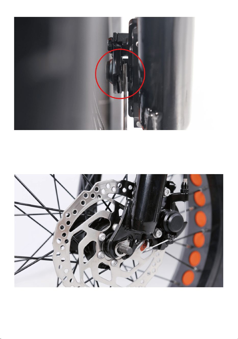
4.Once the lock washers are in place tighten both axle nuts with the
supplied double-open end wrench. Notice: Before doing the final tight-
ening of the axle nuts ,make sure the wheel is square and true with the
forks.
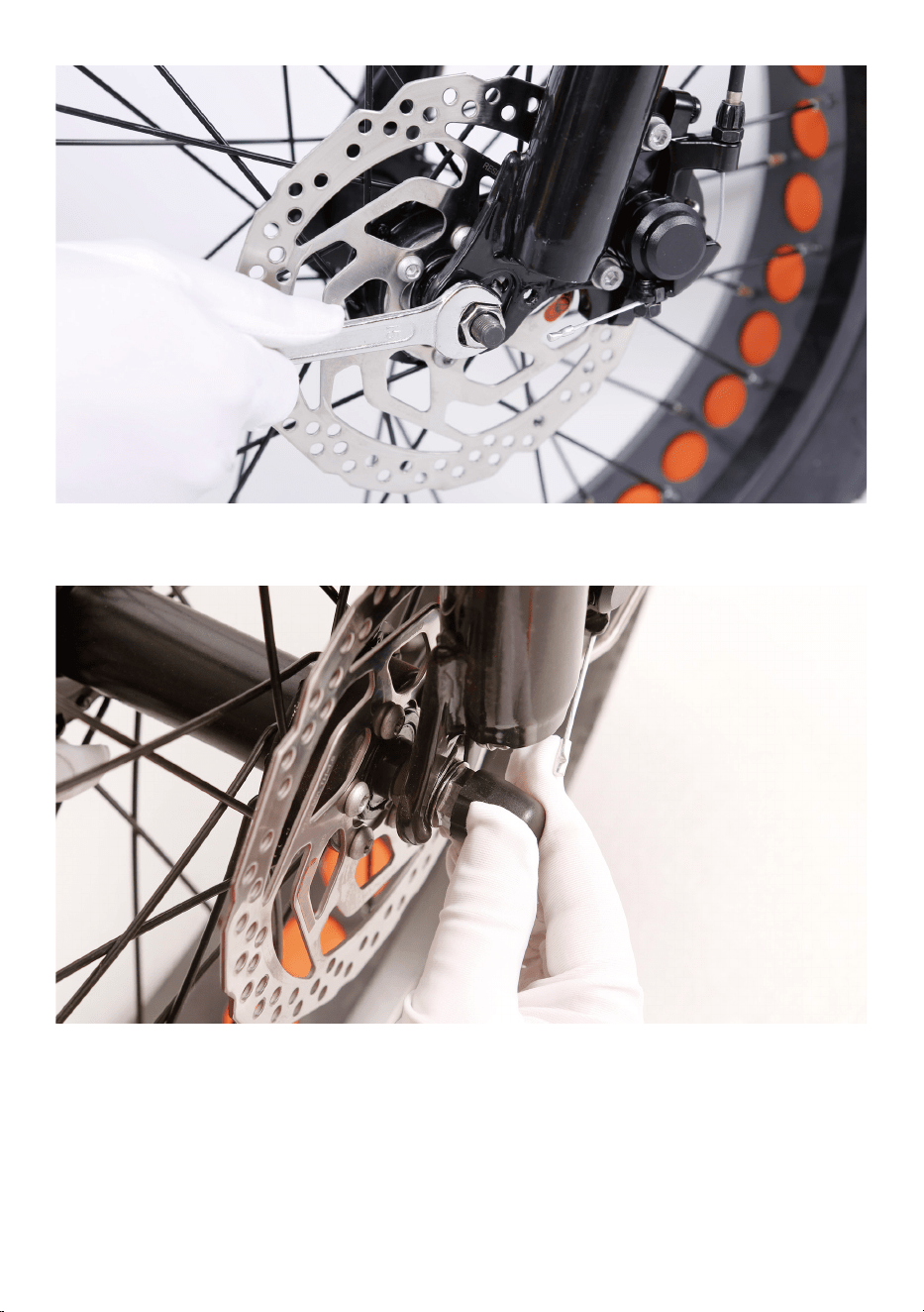
5.Push the black plastic nut caps onto the axle nuts.
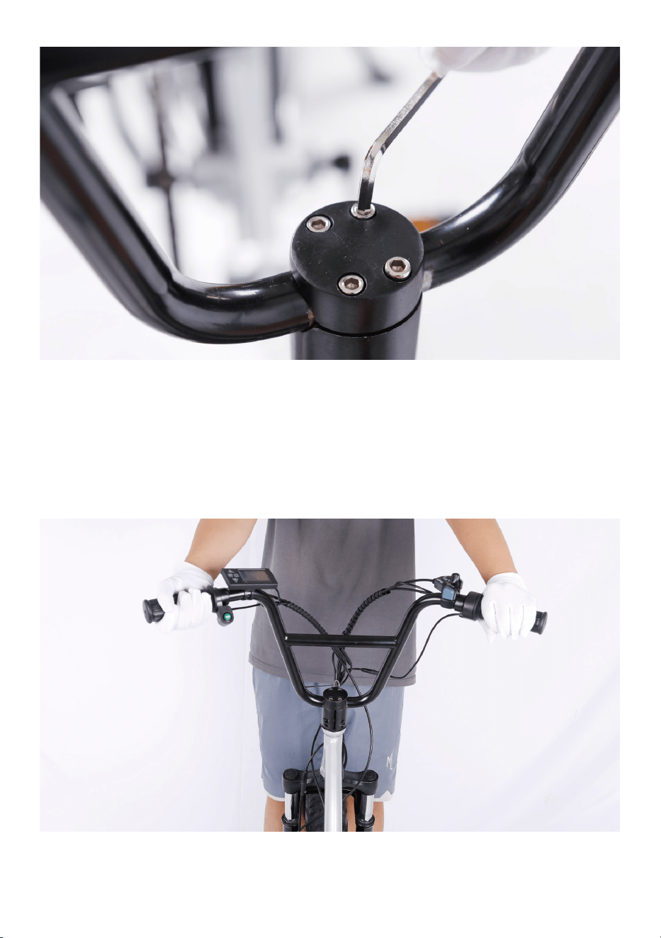
Step Three: Install the handlebar.
1. Loosen the four stem faceplate bolts with supplied Allen wrench,
remove the stem faceplate and set aside.
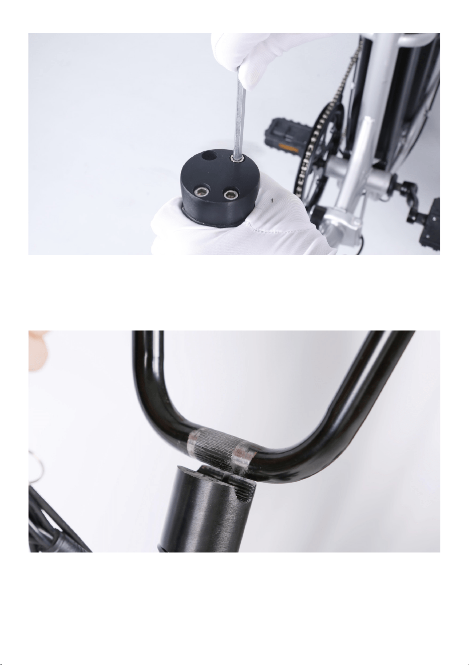
2.Place the handlebar on the stem correctly. Trace the front brake cable
directly up from the front brake caliper to the left handlebar and ensure
the cables and wires are not twisted. Notice: The horn is on the left hand
side and the gear shift is on the right.
3. Center the handlebar and tighten the bolts on stem faceplate evenly.
4.Perform a twist test.
(1).Brace the front wheel between your legs.
(2).Switch hands so the opposite hands are pushing and pulling with
about 20 pounds of force make sure the handlebar and front wheel are
still properly aligned.
(3).Repeat the twist test pulling/pushing with the opposite hands.
Step Four:Adjust the front brake system.
NOTICE: The The adjustment of the front brake system is not easy. The
following steps are only a general guide to assist in the adjustment of the
front brake system. Consult a certified, reputable bike mechanic to assist
with it.
The end goal is a caliper that is parallel to the rotor, with even gap
(2mm-3mm) on each side, and an adequate lever feel. Before adjusting
the front brake system, make sure the axle nuts in Step One have been
tightened.
1.Alignment procedure of the front brake.
Notice: Usually, all bike's rear brake were adjusted in the good condition
at factory. If not, alignment procedures are the same for front and rear
brakes. The end goal here is to keep 2mm-3mm clearance on either side
of the disc brake rotor so that the pads do not rub on the rotor when they
are not applied.
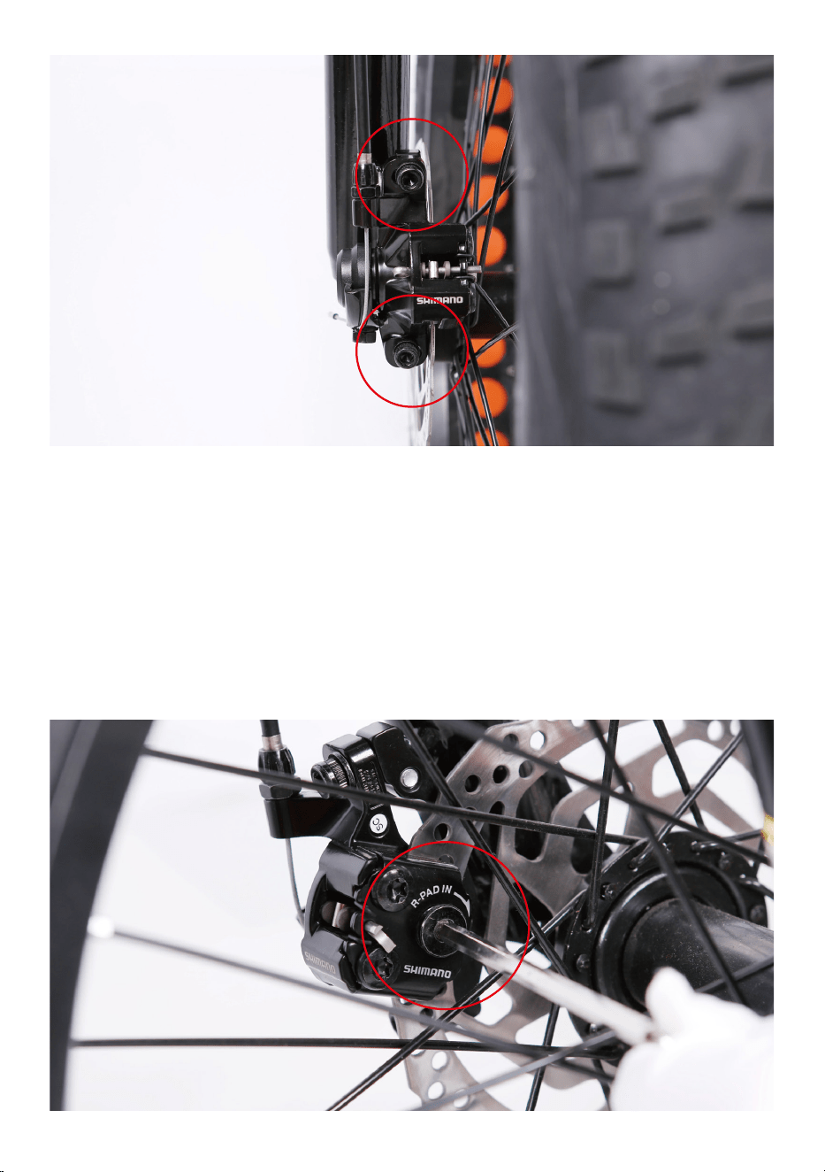
On the front disc brake caliper there are two bolts mounting it to the front
fork. Loosen the mounting bolts until the caliper body is able to freely
move side to side. Then squeeze the brake lever(this centers the caliper
body over the rotor). While holding the lever, tighten the bolts. Release
the brake lever, spin the wheel and check for pad rub. If there is no
rubbing, the pads are aligned. Secure the mounting bolts to full torque
and your work is complete.
If the pads are still rubbing, we need to do some fine-tuning. Loosen one
bolt at a time and adjust until there is a gap on either side of the rotor.
Once the pads are not rubbing, fully secure each mounting bolt and the
process is complete.
To achieve proper gap, it is sometimes necessary to move pads by pad
adjusters. Calipers are equipped with pad adjusters that move the brake
pads in or out from the rotor. Notice: Turning the mounting bolt clock-
wise will move the pad closer to the rotor. Turning it counterclockwise
will move it away from it. Adjust the mounting bolt with the supplied
allen wrench.
Step Five: Install the front fender and headlight.
1.Remove the fender and headlight mounting bolt from the fork arch with
the supplied screwdriver and set aside.
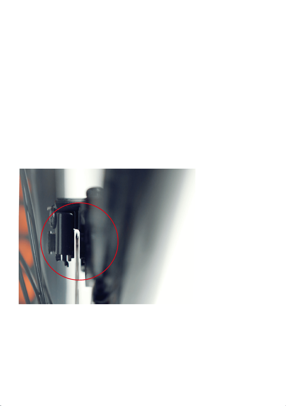
2.Check and adjust the travel at the brake lever at the handlebars.
Typically, the pads should feel like they are contacting the rotor at a
minimum of 1/2 the lever travel. We will get it by adjusting the brake
cable tension.
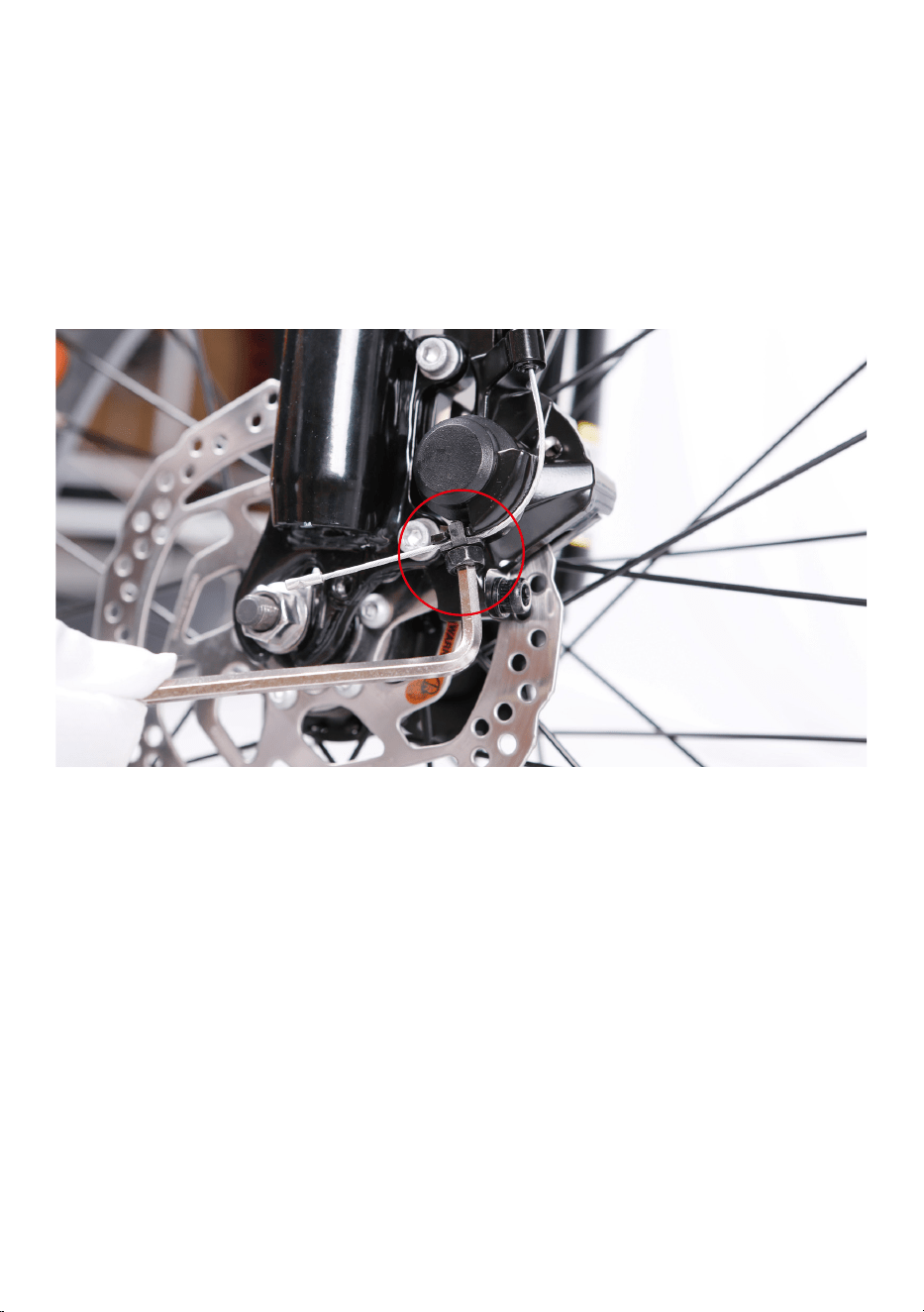
Loosen the bolt on the end of the disc brake caliper arm with the supplied
allen wrench to adjust the brake cable tension. Once achieve the required
tension mentioned above, fully secure the mounting bolt and the process
is complete.
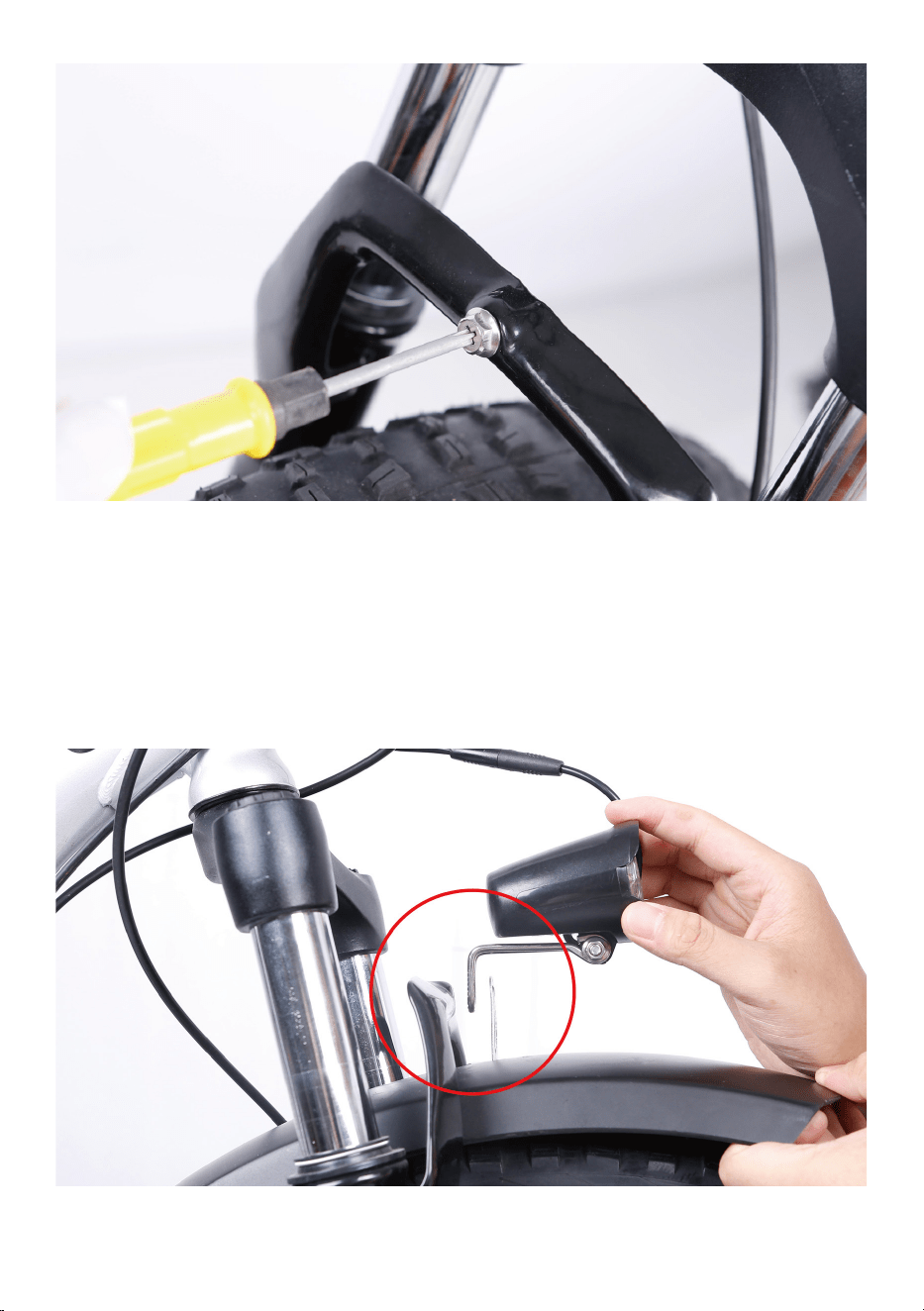
2.Place the fender in position. Pass the front fender mounting point under
the front fork arch from the back of the front tire.
3.Attach the headlight and fender to the fork arch. Pass the bolt through
the headlight mount, the fender mounting point and the fork arch
mounting point. Thread the locknut onto the bolt end and tighten with
the supplied screwdriver. Notice: the fender bracket will go in between
the arch bracket and headlight bracket.
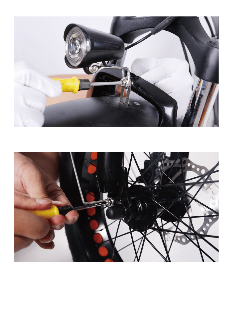
4.Attach the fender mounting arms to the front fork. Ensure the fender is
centered and tignten all mounting bolts.
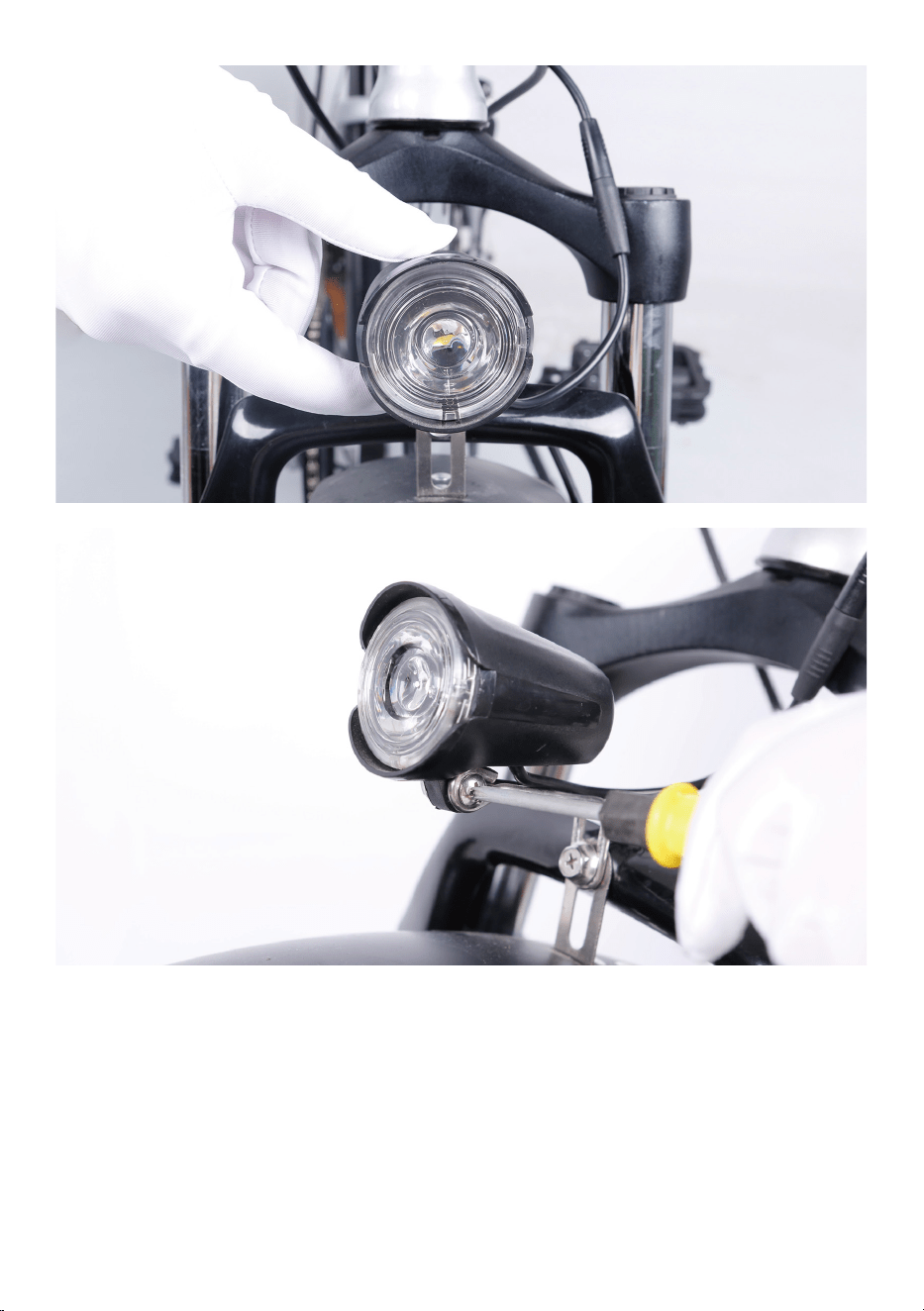
5.Center the headlight and adjust the angle slightly downwards to illumi-
nate the road ahead and not blind oncoming traffic. Use the supplied
Phillips-head screwdriver to loosen the headlight angle adjustment bolt,
tilt the headlight to the optimal position, and then tighten in place
securely.
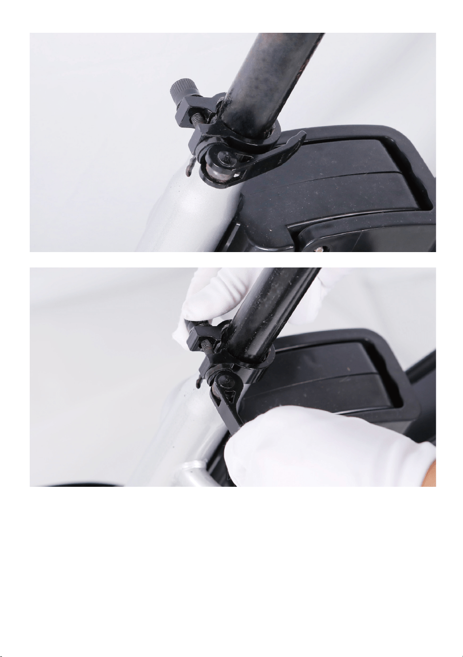
Step Six: Install the seat.
1.Open the quick release lever by hinging it open fully.
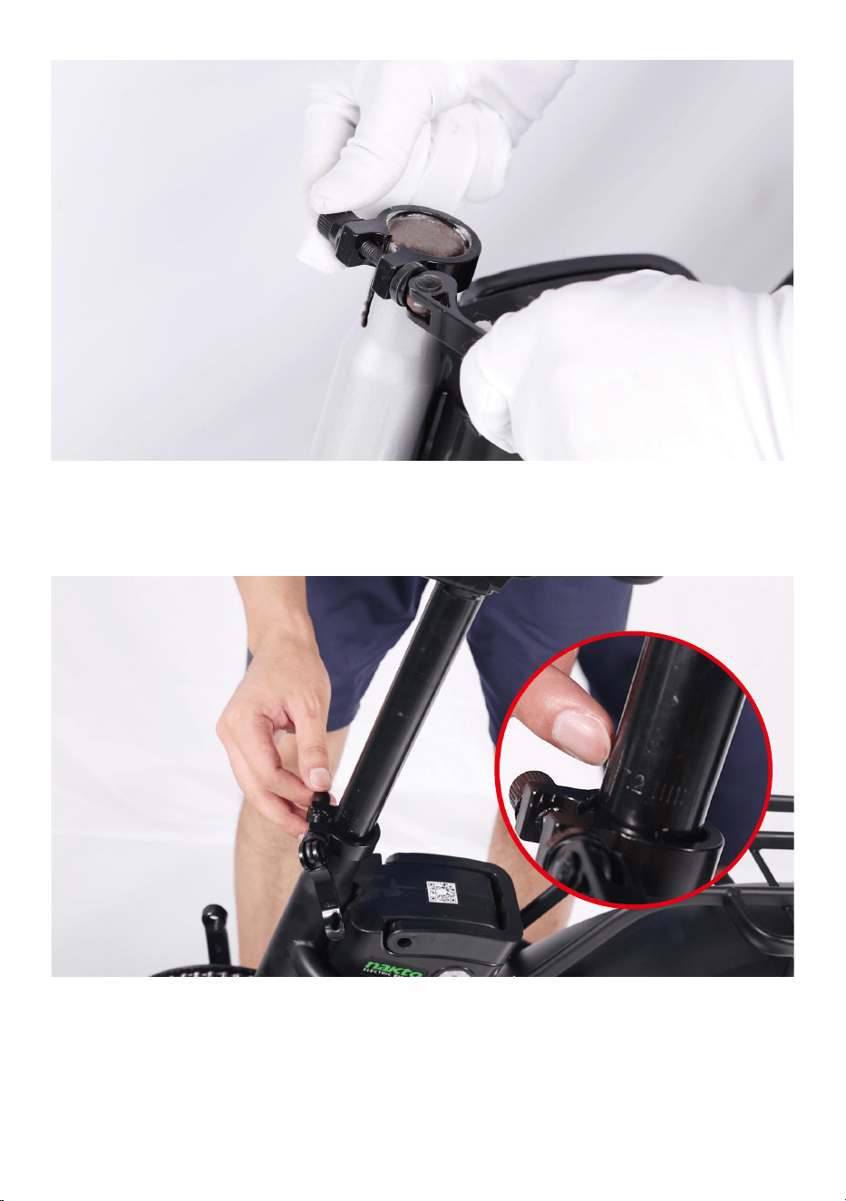
2.Insert seat post into seat tube. Adjust the seat post up or down to a
comfortable height, while ensuring the seat post is inserted into the
frame past the minimum insertion point.
3.Close the quick release lever to secure the seat post and check that it
cannot move. If needed, use the thumb nut to add tension to the clamp
so there is some resistance when the lever is in line with the clamp bolt.
Step Seven: Install the pedals.
1. Locate the pedal with an “R” stamped into the end of the pedal axle,
which indicate it is the right pedal. The right pedal goes on the crank on
the right side of the bike. The remaining pedal with an “L” stamped into
the end of the axle, is the left pedal. The left pedal goes on the crank on
the left side of the bike.
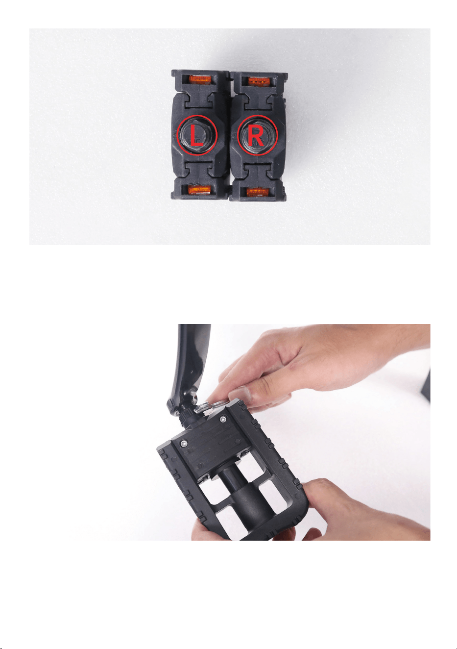
2. The right pedals threaded to tighten by turning clockwise. The left
pedals reverse-threaded and tightens counterclockwise. Carefully thread
the pedal onto the crank by hand slowly.
3.Further tighten with the supplied double open-end wrench. Do not
cross thread or damage the threads.
Step Eight: Inflate the tires.
Check that the tire beads and tires are evenly seated around the rims. Use
a pump with a Schrader valve and pressure gauge to inflate each tire to
the recommended pressure indicated on the tire sidewall. Do not overin-
flate or underinflate tires.
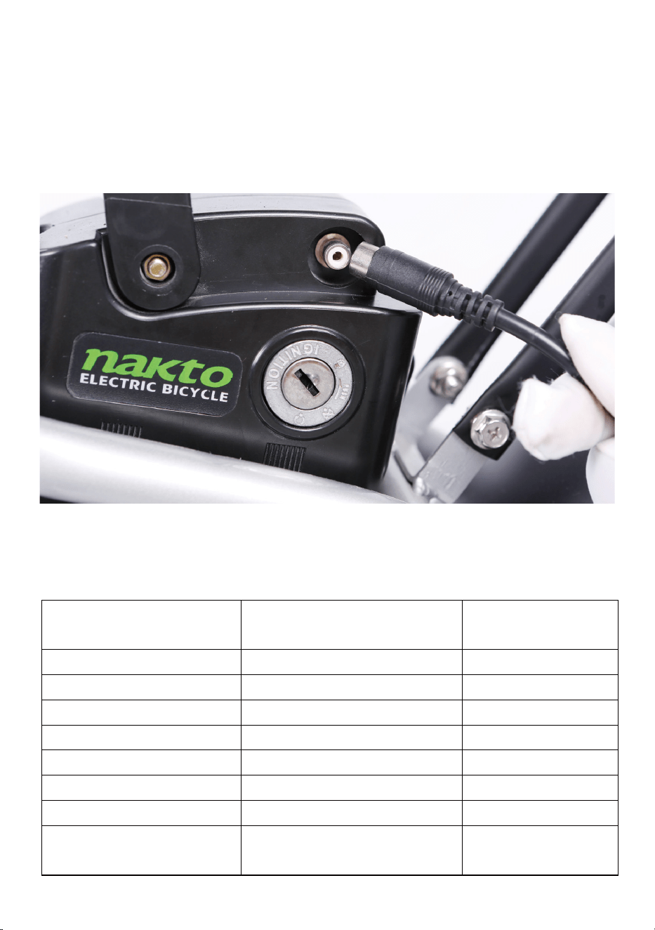
Step Nine: Charge the battery.
Operate the electrical system when the battery has been adequately
charged and the battery is secured to the frame mount.
Your Nakto bike comes partially charged. We recommend you Connect
the charger input plug (110/220-volt plug) to the power outlet for 3 to 4
hours. The charger light will go from red to green when it is fully charged.
Step Ten: Ensure all hardware is tightened properly
following recommended torque values.
Recommended Torque Values:
Hardware Loca�on Hardware
Torque Required
(Nm)
Front Dropout Area
Front Axle Nuts
40
Handlebar Area
Handlebar Stem Clamp Bolts
10
Handlebar Area
Brake Lever Clamp Bolt
6
Handlebar Area
Shi�er Clamp Screw
6
Brakes
Caliper Adapter to Frame
8-10
Brakes Pad to Caliper Arm 6
Brakes Brake Cable to Caliper Clamp
6
Fenders
All Fender Moun�ng Bolts
and Hardware
6

Step Eleven:Register warranty card with us ASAP.
Notice: Keep proof of purchase in a safe place. Keep packing and box for
at least two weeks from the date of purchase. (As we do not provide a
box for returns if needed.)
Have fun and be safe!
Hardware Loca�on Hardware
Torque Required
(Nm)
Headlight
Headlight Angle Adjustment
Bolt
6
Basket Area
All Basket Moun�ng Bolts
and Hardware
6
Seatpost Area
Seat Angle Adjustment Bolt
20
Rear Dropout Area
Rear Axle Nuts
40
Rear Dropout Area
Rear Torque Arm Bolt
5
Rear Dropout Area
Derailleur Hanger Moun�ng
Bolt
6
Rear Dropout Area
Derailleur Moun�ng Bolt
10
Rear Dropout Area
Derailleur Cable Pinch Bolt
6-8
Rear Dropout Area
Kickstand Moun�ng Bolts
8
Bo�om Bracket and
Crank Area
Bo�om Bracket and Lockring
60
Bo�om Bracket and
Crank Area
Crank Arm Bolt into Bo�om
Bracket Spindle
35
Bo�om Bracket and
Crank Area
Pedal into Crank Arm 35
Bo�om Bracket and
Crank Area
Chainring Bolts 10
Bo�om Bracket and
Crank Area
Controller Moun�ng Bolts 6
Quick Start Guide
This ebike is equipped with two ways for a rider to use power assistance
from the motor to propel the bike forward:
The pedal assist system (PAS) ⸺The rider can engage the pedal assist
system (PAS) while pedaling, and it will call up assistance from the motor
to help propel the bike forward.
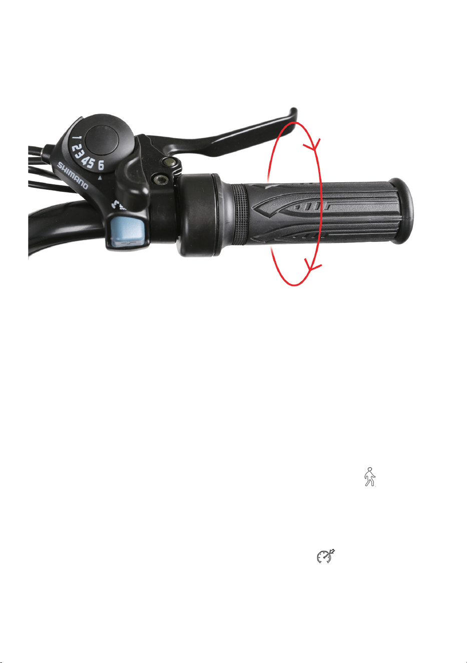
The twist throttle⸺The throttle is located on the right side of the
handlebar. The rider can use it with a twist of the throttle grip to propel
the bike forward without pedaling.
Warning: The throttle is active whenever the bike is turned on. Do not use
the throttle unless you are on the bike.
Start-Up Procedure
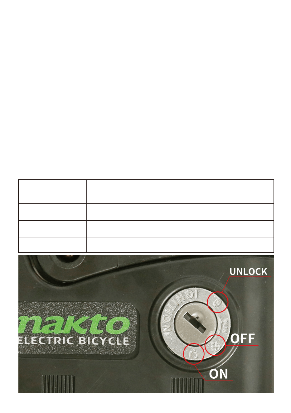
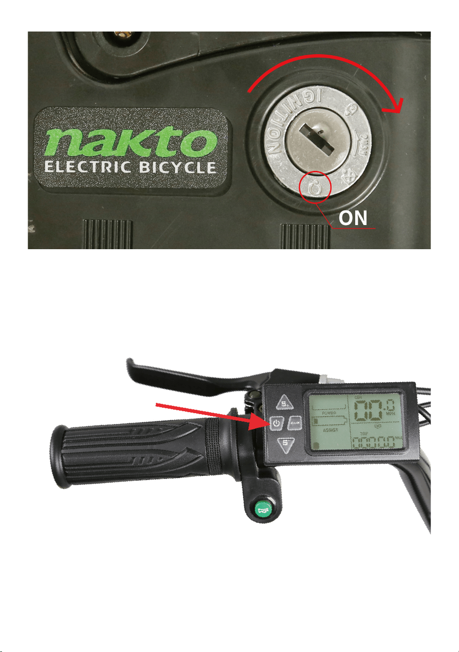
1.Turn on the battery with the key. Insert the key and turn clockwise to
position (1).
Battery Key Positions
Key Position /
Icon
Description
1
2
3
ON , Locked to the frame
OFF, Locked to the frame
OFF, Unlocked (ready for removal from the frame)
2.Sit on the bike.
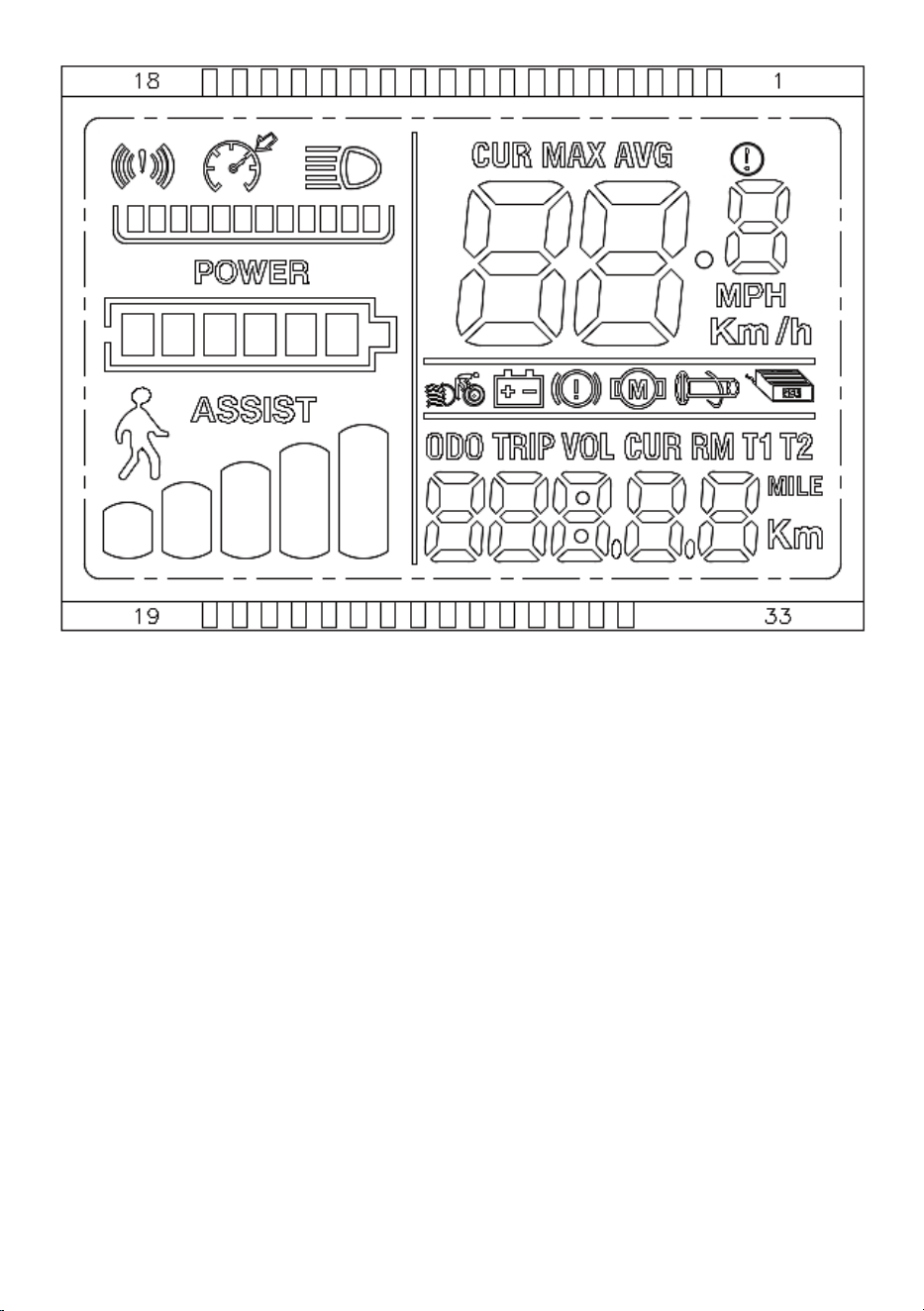
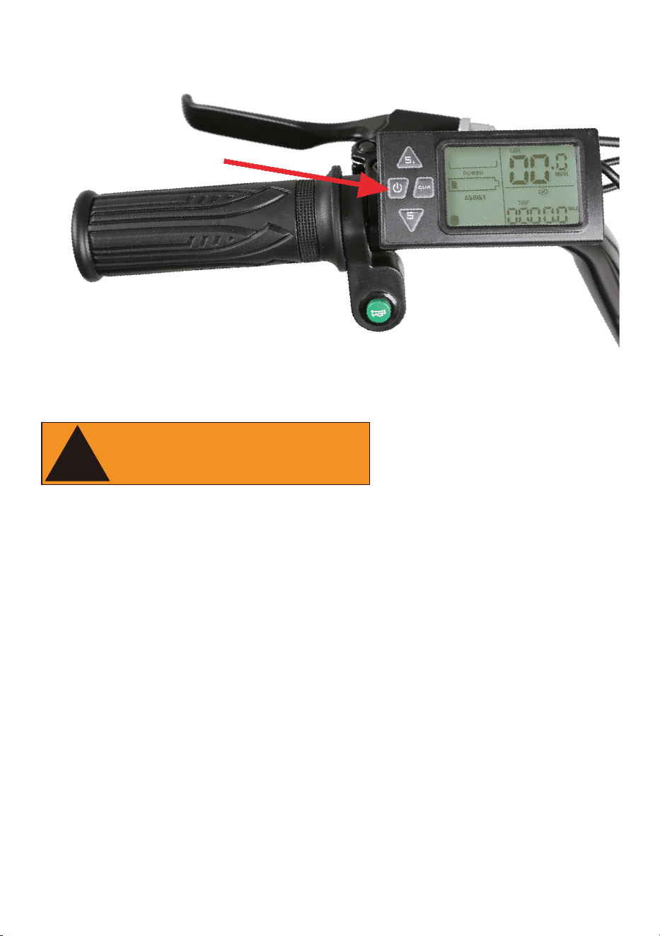
3.Turn on the electrical system⸺Press and hold the start button on
LCD display panel for approximately 3 seconds until power is delivered to
the LCD Display.
4.Turn on the headlight if needed or desired. Once the LCD Display is on,
press “CUR” button to turn the headlight on. Press it again to turn the
headlight off.
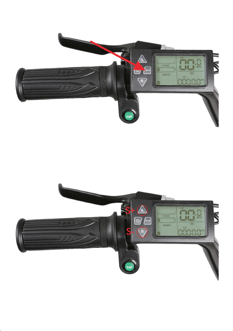
5.Select the desired level of pedal assistance⸺Select the level from
0-3 by pressing “S+” and “S-” . Level 1 corresponds to the lowest level of
pedal assistance, and level 3 corresponds to the highest level of pedal
assistance. Level 0 indicates pedal assistance is inactive. Start in PAS level
0 or 1 and adjust from there.
6.Begin riding carefully⸺Hold handlebars and start pedaling on a flat
surface, in a low gear (1 or 2), most riders should be able to begin pedal-
ing the bike with pedal assist level 0 or 1. You may also use the throttle to
accelerate and maintain your desired speed.
Do not use the throttle while dismounted. Avoid accidental application of
the throttle while dismounted; anytime you are moving the bike while
dismounted, ensure the bike is powered off to prevent accidental applica-
tion of the throttle.
8.Brake⸺Brake the bike by squeezing the brake lever (Notice: as a
safety feature applying either front or rear brake will disengage the
motor.)
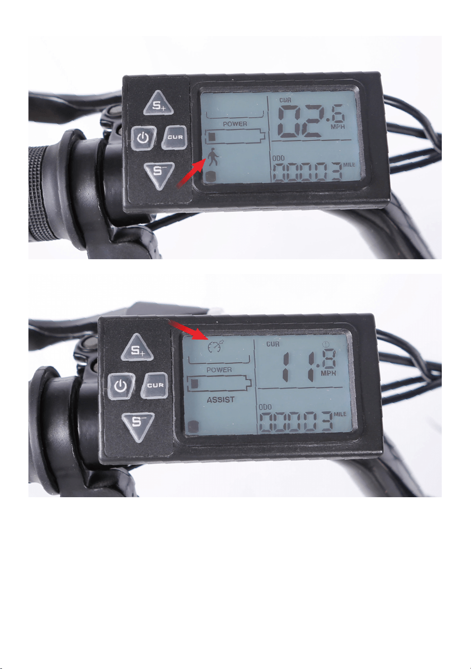
9.Cruise Control:
This ebike is equipped with two mode of cruise control:
Walk Cruise Mode---While dismounted, press and continue to hold down
“CUR”. The walk cruise mode is active. The indicator lights in the LCD
display light up. A speed of 6kg/h is maintained. Warning: Walk mode
should only be used while dismounted from the bike and with both hands
on the handlebar.
Ride Cruise Mode---While riding, press and continue to hold down “CUR”.
The ride cruise mode is active. The indicator lights in the LCD display
light up. The current speed is maintained and stored as desired speed.
7.The throttle is used by slowly and carefully rotating the throttle back-
ward toward the rider. The more you twist, the more powerfully the
throttle will propel the bike forward.
Switching off---Press and continue to hold down “CUR” to switching
cruise control.
Warning:Always keep at least one hand on a brake lever to allow quick
cutoff of the motor assistance if necessary and to maintain control of the
bike.
The desired speed can be incorrectly adjusted or called up by mistake.
There is a risk of an accident. Adjust the desired speed to the traffic
conditions. Watch traffic closely and actively intervene where appropri-
ate.
10.Turn off the electrical system by pressing and holding the start
button approximately 3 seconds again before getting off the bike.
We recommend that you always wear protective gear when cycling such
as a helmet, gloves, elbow pads and goggles.
When riding, obey the same road laws as all other road vehicles as appli-
cable by law in your area.
Best to charge the battery during the day when someone is around.
Overnight charging is not recommended.
Before riding always carry out a through safety check each time. We
highly recommend that you read the instruction manual before your very
first ride.
It is the user’s responsibility to ensure a potential passenger on the Nakto
eblike is adequately experienced and healthy enough to ride safely as a
passenger. Serious injury or death can occur if passengers are inexperi-
enced or in poor health such that it impacts their ability to ride as passen-
gers safely.
Carrying baggage may reduce the control of your ebike.
Take extra care while riding in wet and sandy surface including decreasing
speed and increasing braking distances.
11.Turn off the battery and remove the key when you park.
!
WARING

Trek Power Inc
Toll Free: 1-855-997-7297
E-mail: support@nakto.com
Website: www.nakto.com
Adress:1683 Sierra Madre,Placentia,CA 92870
ELECRTIC
BICYCLE