
2
CONTENTS
IMPORTANT SAFETY INFORMATION
3
PARTS
5
INSTALLATION
6
CHANGING THE VENTILATION METHOD
6
CHANGING THE VENTILATION OUTLET
7
PREPARING FOR INSTALLATION
8
CUPBOARD MOUNTING INSTALLATION
9
WALL MOUNTING INSTALLATION
10
OPERATION
11
REPLACING THE BULB
12
INSTALLING THE OPTIONAL CARBON FILTER
12
CLEANING AND MAINTENANCE
13
TROUBLESHOOTING
14
SPECIFICATION
15
MANUFACTURER SUPPORT
16

3
IMPORTANT SAFETY INFORMATION
Please read this instruction manual carefully and retain for
future reference. It contains important information concerning
the safe operation, installation and maintenance of the
appliance.
There must be adequate ventilation of the room when the
hood is used at the same time as appliances burning gas or
other fuels.
This cooker hood is only designed for domestic use, and
should not be used in a commercial environment.
Never use the hood for any purpose other than its intended
use.
Do not check the status of the filters during operation of the
cooker hood.
Do not touch the light bulb within 30 minutes of use.
Do not flambé or excessively flame under the hood.
Never leave frying food unattended as it can be a serious
fire hazard.
If the supply cord is damaged, it must be replaced by the
manufacturer, its service agent or a similarly qualified
person in order to avoid a hazard.
The socket outlet for the hood must be located so it is easily
accessible for the user after installation.
Ensure the mains supply voltage corresponds with that of
the appliance.
There is a fire risk if cleaning is not carried out in
accordance with the instructions.
Ensure that the socket used provides adequate earthing of
the appliance, if unsure professional advise must be sought.
This appliance can be used by children aged from 8 years
and above and persons with reduced physical, sensory or
mental capabilities or lack of experience and knowledge if
they have been given supervision or instruction concerning
use of the appliance in a safe way and understand the
hazards involved.

4
Children must not play with the appliance.
Cleaning and user maintenance must not be carried out by
children without supervision.
When the hood is being maintained, cleaned or filters
changed, make sure it is switched off at the mains supply.
The exterior of the hood should be cleaned with mild
detergent on a warm damp sponge or cloth.
The air must not be discharged into a flue that is used for
exhausting fumes from appliances burning gas or other
fuels.
Regulations concerning the discharge of air have to be
fulfilled.
The minimum distance between the supporting surface for
the cooking vessels on the hob and the lowest part of the
hood must be at least 65 cm.
When the cooker hood is used in conjunction with
appliances supplied with energy other than electric, the
negative pressure in the room must not exceed 0,04 mbar
to prevent fumes being drawn back into the room by the
cooker hood.
Failure to install the hood in accordance with these
instructions may result in electrical hazards.
CAUTION:
Accessible parts may become hot when used with cooking
appliances.
Deep fat fryers must be continuously monitored during use:
overheated oil can burst into flames
5
PARTS
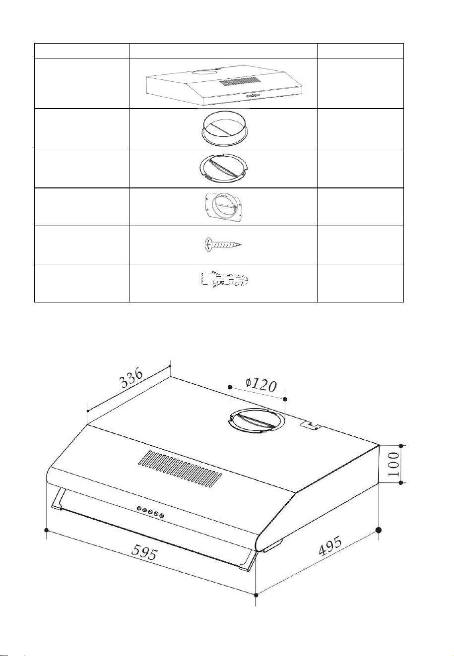
DIMENSIONS
Description
Illustration
Qty
Cooker hood
1
Outlet
assembly
1
Outlet cover
1
Rear Air Flow
Adaptor
1
Screw
(4mm x 30mm)
6
Wall plug
6
6
INSTALLATION
BEFORE INSTALLING YOUR CANOPY HOOD:
Please read the instructions carefully.
Unpack the hood and check that all functions are working.
Ensure that the voltage (V) and the frequency (Hz) indicated
on the serial plate match the voltage and frequency at the
installation site.
Check that the area behind the installation surface to be drilled
is clear of any electrical cables or pipes, etc.
The surfaces of the canopy are very easily damaged during
installation if grazed or knocked by tools. Please take care to
protect the surfaces during installation.
Protect the cooktop surface below with cardboard, or similar,
to prevent damage occurring whilst the hood is being installed
above.
The manufacturer shall not be liable for any failure to observe all
safety regulations in force for the correct and normal operation of electrical
products.
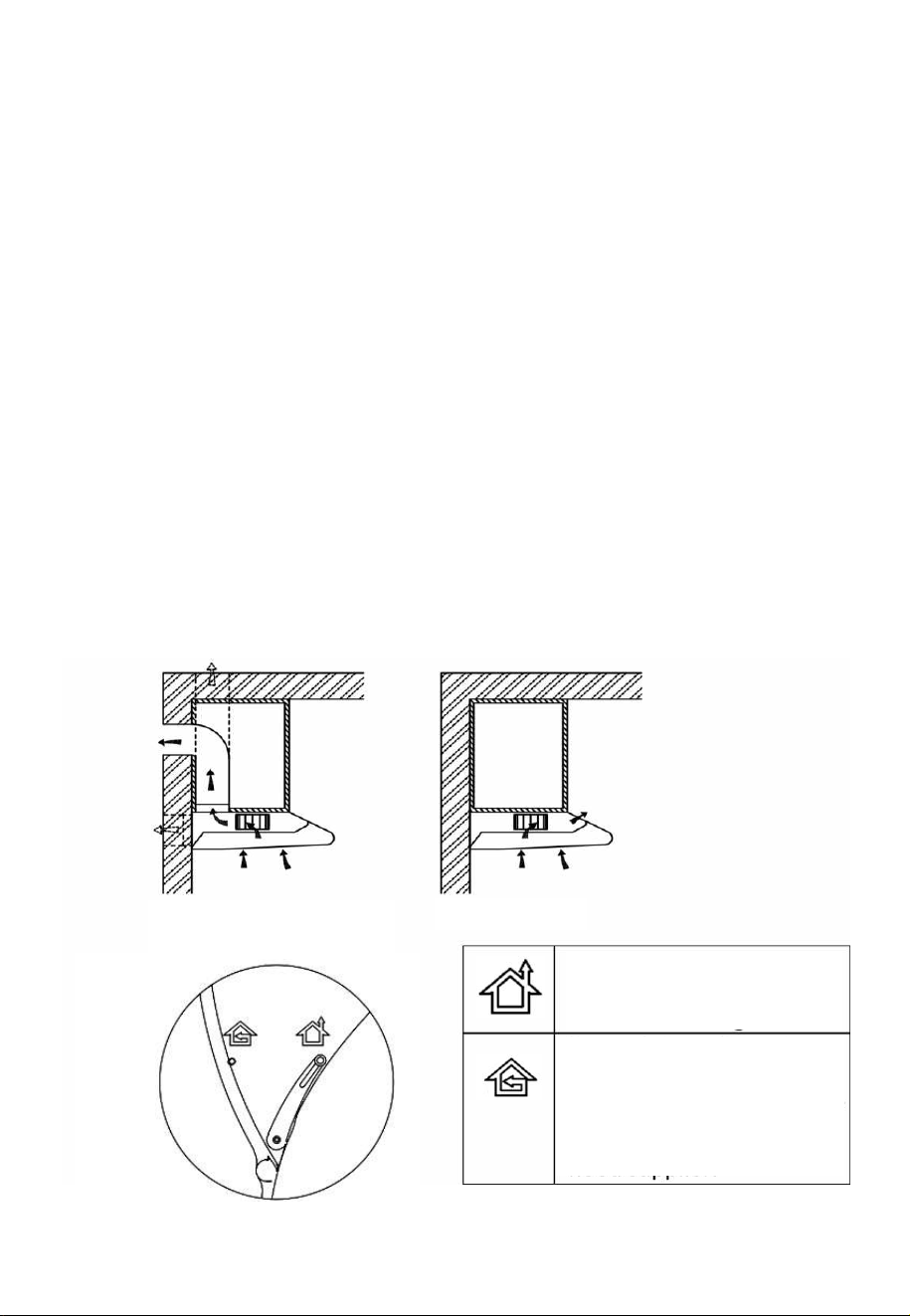
CHANGING THE VENTILATION METHOD
EXTRACTION MODE
Turn the lever to this position when
using with an external vent pipe
RECIRCULATE MODE
Turn the lever to this position
when venting back into the room.
This mode must be used with an
optional carbon filter.
EXTRACTION
(TOP OR
REAR VENT)
RECIRCULATE
7
INFORMATION
Sufficient air is needed for proper combustion and exhaustion of
gases through the flue (chimney) of fuel burning equipment to
prevent back drafting. Ductless fans must always be vented to
the outdoors.
When assessing the air pressure, the entire ventilation system
in the house/apartment must be taken into account.
All legal regulations must be observed for the conveyance of
exhaust air. If the extractor hood is used in recirculating mode
with the optional carbon filter, there are no operating restrictions.
Make sure the vent option knob is set correctly (page 6).
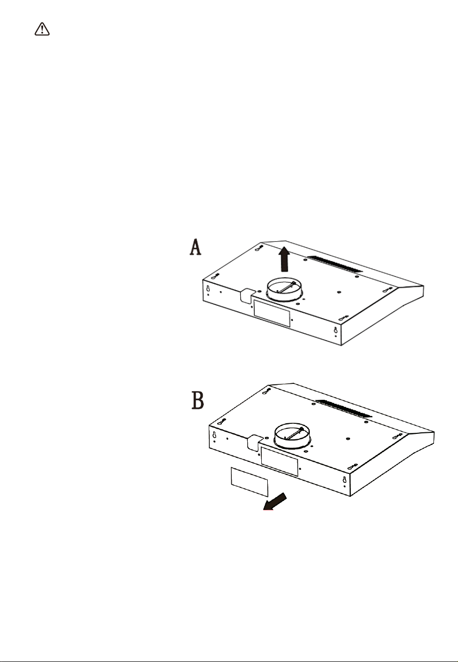
CHANGING THE VENTILATION OUTLET (EXTRACTION MODE)
As well as providing the
options of recirculation or
extraction, when the unit
is externally vented, it can
be vented either vertically
out of the top of the unit,
or horizontally out of the
back.
The default set up is
vertical venting. To vent
the unit horizontally,
remove the check valve
from the top of the unit,
and replace with the air
outlet cap. Remove the
plate from the rear of the
hood. And fit the rear air
flow adaptor, securing
with 4 screws.
8
PREPARING FOR INSTALLATION:
Ensure the power has been
turned off at the mains before
beginning installation.
Connection to the mains supply
must be in an accessible
location. To install this hood
you will require two assistants.
You may need the following
tools to complete this
installation:
Drill appropriate for your
wall
Phillips Screwdriver
Tape Measure
Hand Saw or Jig Saw
Electrical wiring must be done
by a qualified person in
accordance with all applicable
codes and standards, including
fire rated construction.
Do not discharge the exhaust air into a flue from other appliances
burning gas or other fuels.
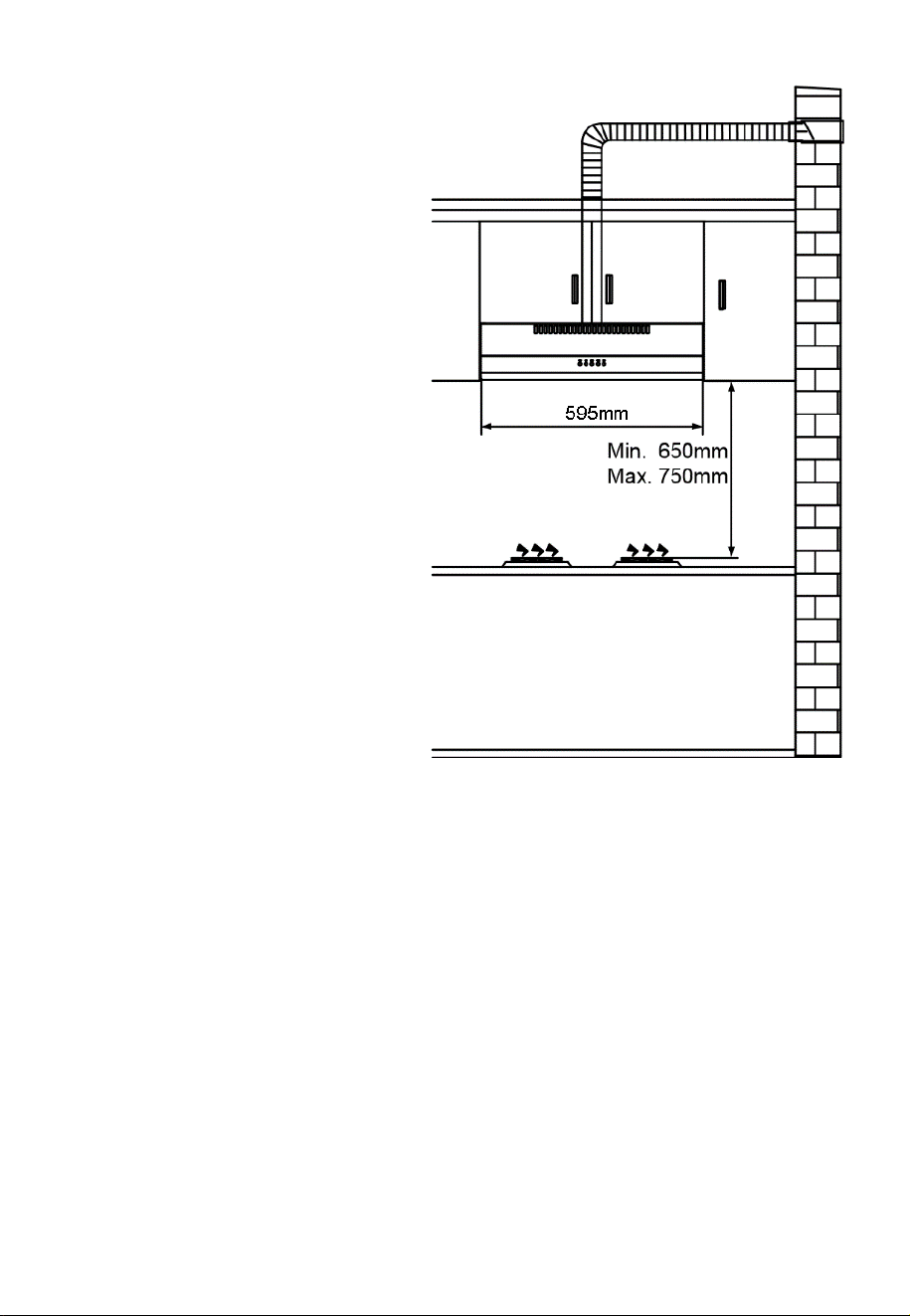
The cooker hood must be placed at a minimum distance of 65cm
above the cooking surface of a hob.
9
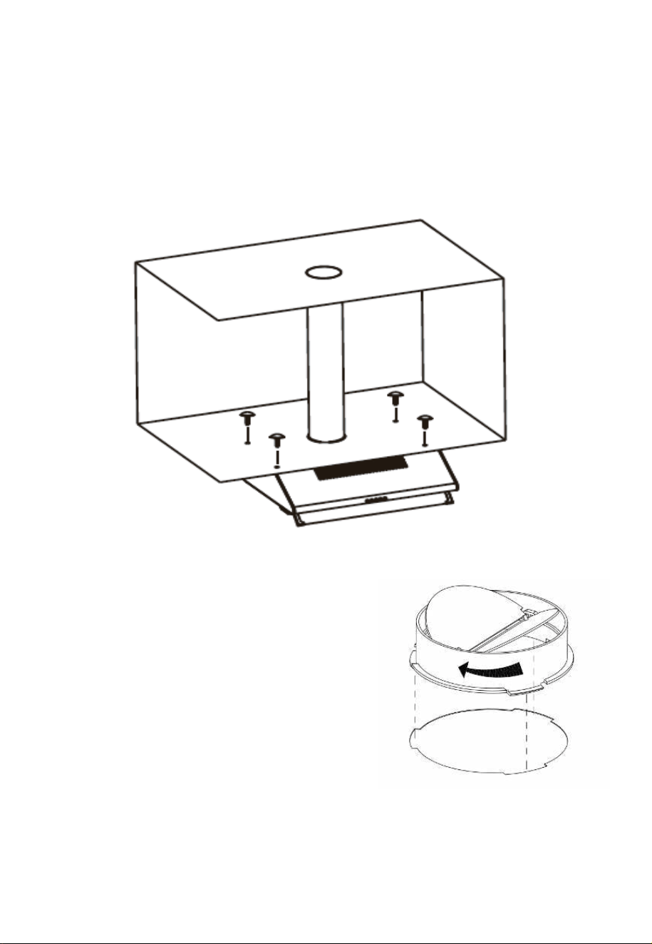
CUPBOARD MOUNTING INSTALLATION:
1. Drill a 130mm diameter and four 6mm diameter holes as shown in the
diagram.
NOTE: If your cooker hood is to be used in recirculating air mode or is
configured for rear venting, it is not necessary to cut the 130mm
diameter hole.
2. Attach the one way valve and then
use 4 screws to fix the cooker hood
to the underside of the kitchen
cupboard. Check that your fixings
are correctly located, by temporarily
fitting the cooker hood. If correct, fit
the unit into position. Tighten the
screws as necessary.
10
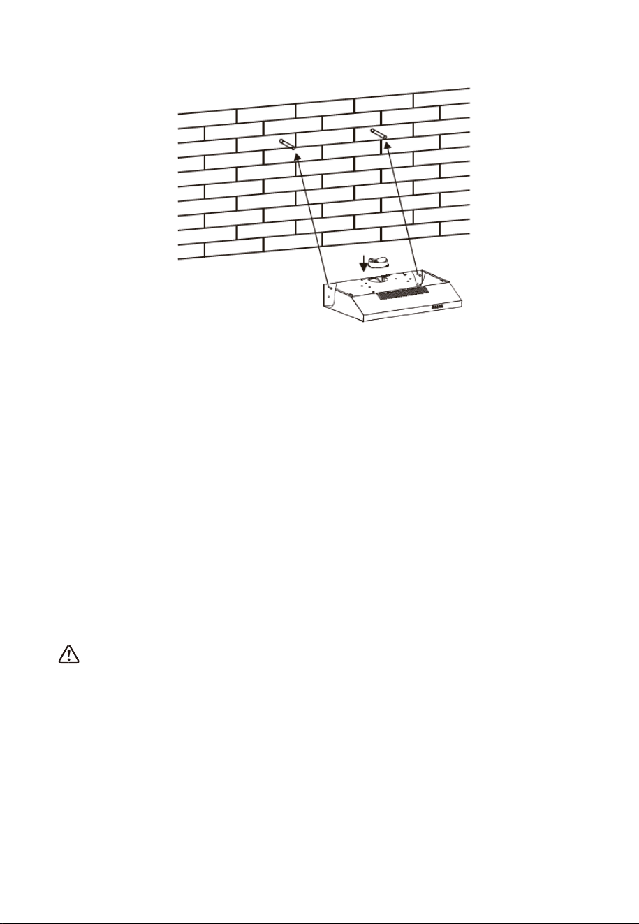
WALL MOUNTING INSTALLATION:
1. Drill two 8mm diameter holes in the correct position on the wall when
compared to the hanging holes on the rear of the hood. Make sure
the hood is aligned directly over the hob, a minimum of 65cm above
the hob surface.
2. Insert two plastics wall plugs into the holes.
3. Insert two screws into the wall plugs and tighten them leaving around
3mm protruding from the wall.
4. Mount the cooker hood onto the two screws and mark the bottom two
screw positions.
5. Remove the hood and drill the bottom two screw holes and insert the
plastic wall plugs.
6. Mount the hood on the top screws, insert the bottom screws and fully
tighten all the screws.
Information
The air must not be discharged into a flue that is used for
exhausting fumes from appliances burning gas or other fuels.
11
OPERATION
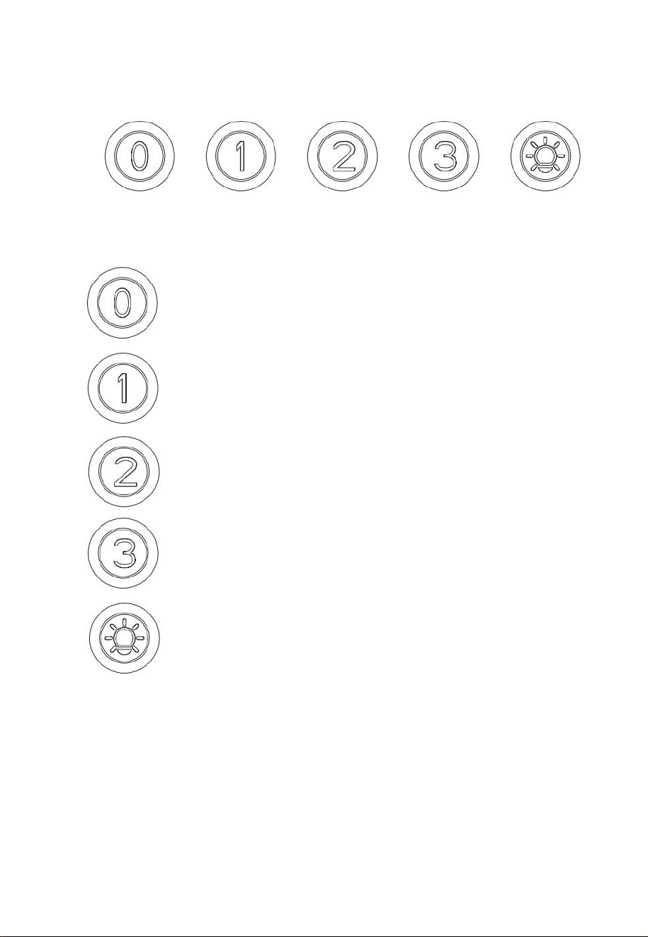
MOTOR OFF BUTTON:
Press on this switch to stop operation of the
motor.
LOW SPEED BUTTON:
Press to run the motor at LOW speed.
MEDIUM SPEED BUTTON:
Press to run the motor
at MEDIUM speed.
HIGH SPEED BUTTON:
Press to run the motor
at HIGH speed.
LIGHT ON/OFF BUTTON:
Press to turn on the lights, press again to
turn them off.
12
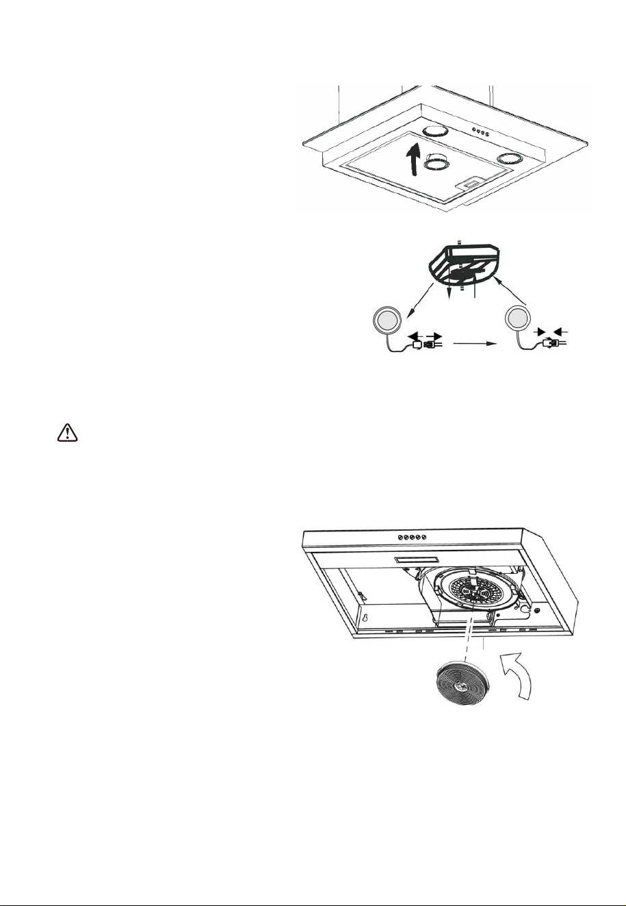
REPLACING THE BULB
1. Switch off the extractor
hood and ensure it is also
switched off at the mains
supply.
2. Remove the grease filter.
3. Unclip the lamp holder
using the spring clip on the
rear of the holder.
4. Disconnect the wiring connector on
the lead running from the lamp
holder.
5. Replace the holder and lamp with
identical unit available from the
retailer/manufacturer.
6. Remember to switch on at the mains once installation is
completed and the hood has been fully reassembled.
Information
Clean ventilation fans frequently. Grease should not be allowed to
accumulate on fan or filter.
INSTALLING THE OPTIONAL CARBON FILTER:
1. Remove the grease filter
2. The carbon filter is located
at the end of the motor. To
fit, rotate the filter
clockwise onto the motor
housing; to remove, rotate
filter anti-clockwise until it
is unscrewed.
Warning: the carbon filter cannot be washed or recycled. It should
be replaced after approximately 2-3 months of use.
Note: The optional carbon filter is available from the hood
supplier/manufacturer under stock code: eiQVISTMCARBON
13
CLEANING AND MAINTENANCE
Disconnect range hood from power supply before cleaning or
servicing.
1. Clean the hood surface frequently using mild detergent and a
warm damp sponge or cloth.
2. Do not use harsh alkalis or abrasives.
3. Avoid the use of scouring powers or dishwasher compounds.
4. If the optional carbon filter is being used, these cannot be
cleaned and require replacing every 2-3 months depending on
frequency of use. They are available from the retailer who
supplied your hood.
Information
Cleaning water must be kept away from the motor, control switch
and all electrical components.
It is recommended that the grease filter is cleaned every two to
three months by carrying out the following instruction:
1. Remove the grease filter from the cooker hood and wash it in a
solution of warm water and neutral liquid detergent, leaving to
soak.
2. Rinse thoroughly with warm water and allow to dry thoroughly
before refitting.
3. The metallic filter may alter in colour after several washes.
There is a fire risk if cleaning is not carried out in accordance with
the instructions.
14
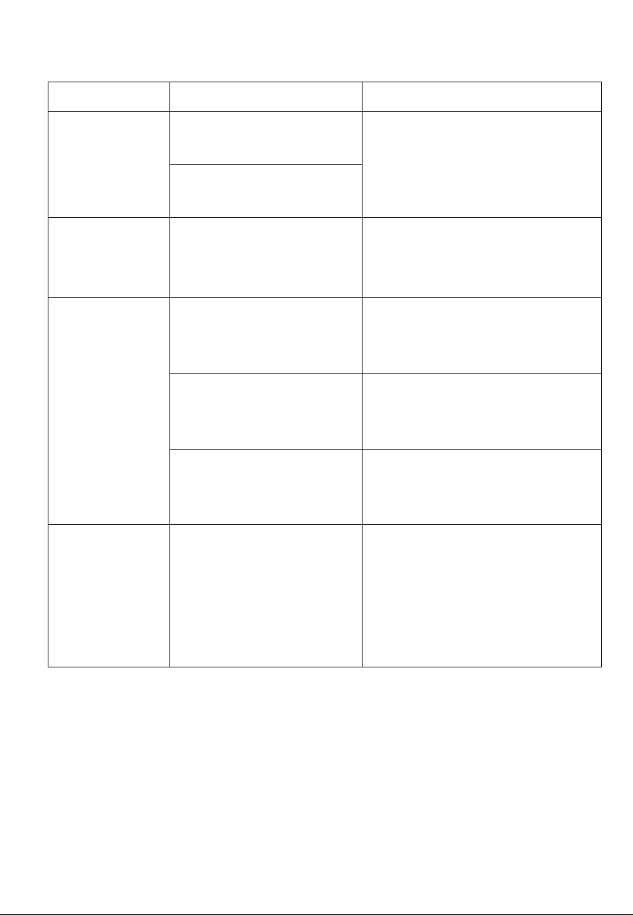
TROUBLESHOOTING
Fault
Cause
Solution
Light on, but
fan does not
work
The fan blade is
jammed.
Switch off the unit. Repair to
be carried out by qualified
service personnel only.
The motor is
damaged.
Both light
and fan do
not work
Power cord loose
Plug in to the power supply
again.
Excessive
Vibration
The fan blade is
damaged.
Switch off the unit. Repair to
be carried out by qualified
service personnel only.
The fan motor is not
fixed tightly.
Switch off the unit. Repair to
be carried out by qualified
service personnel only.
The unit is not hung
properly on the
bracket.
Take down the unit and
check whether the bracket is
in proper location.
Suction
performance
not good
1. Grease filters
clogged
2. Distance between
the unit and the
cooking plane too
great.
1 Clean or replace grease
filters.
2 Adjust the distance to
between 70cm and 80cm.
15
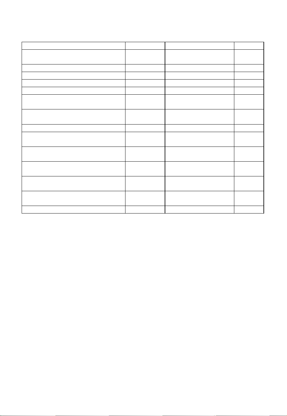
SPECIFICATION
Symbol
Value
Unit
Model identification
eiQTMVISORWH
eiQTMVISORSTEEL
Annual Energy Consumption
AEChood
33.55
kWh/a
Time increase factor
f
1.65
Fluid Dynamic Efficiency
FDEhood
9.6
Energy Efficiency Index
EEIhood
73.52
Measured airflow rate at the best
efficiency
QBEP
95.86
m3/h
Measured air pressure at best
efficiency point
PBEP
191.91
Pa
Maximum airflow
Qmax
201.55
m3/h
Measured electric power input at
best efficiency point
WBEP
53.16
W
Nominal power of the lighting
system
WL
2
W
Average illumination of the lighting
system on the cooking surface
Emiddle
94
lux
Measured power consumption on
standby mode
PS
--
W
Measured power consumption on
off mode
PO
0
W
Sound power level
LWA
70
dB
The following shows how to reduce total environmental impact (e.g.
energy use) of the cooking process).
(1) Install the cooker hood in a proper place where there is efficient
ventilation.
(2) Clean the cooker hood regularly so as not to block the airway.
(3) Remember to switch off the cooker hood light after cooking.
(4) Remember to switch off the cooker hood after cooking.
16
MANUFACTURER SUPPORT
www.electriQ.co.uk
Unit J6, Lowfields Business Park
Lowfields Way, Elland
West Yorkshire, HX5 9DA
Telephone: 0871 984 4416
Office Hours: 9:00am to 5:00pm Monday to Friday
ENVIRONMENTAL PROTECTION
Waste electrical products should not be disposed of
with household waste. Please recycle where facilities
exist. Check with your Local Authority or retailer for
recycling advice.
INFORMATION FOR DISMANTLING
Do not dismantle the appliance in a way which is not shown in the user
manual. The appliance could not be dismantled by user. At the end of
life, the appliance should not be disposed of with household waste.
Check with your Local Authority or retailer for recycling advice.