Questions, problems, missing parts?
Before returning to your retailer, call our customer service at 1-800-887-6326.
Monday – Friday 9:00 a.m. – 5:00 p.m. CST
SKU Number: 343-4164
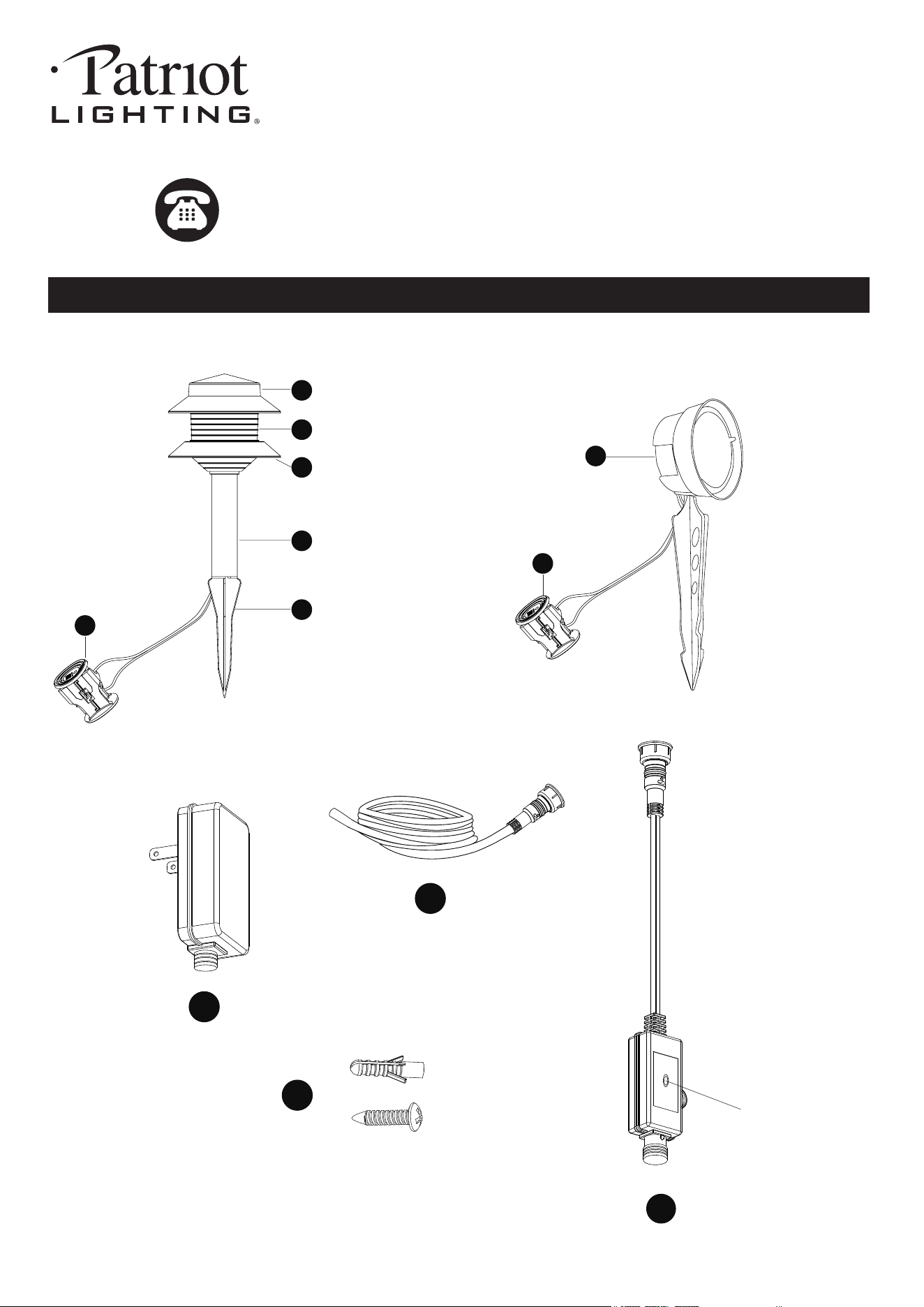
Low Voltage LED Light Set
Model Number: LV21028 BK
221024
Photocell
I
H
K
J
PACKAGE CONTENTS
A
B
D
E
F
C
G
F
X 8
X 2
Page 2 of 6
SAFETY INFORMATION
Please read and understand this entire manual before attempting to assemble, operate or install the product.
WARNING
Do not install within 10 feet (3 m) of a pool, spa or fountain.
For use with 12 volt low voltage outdoor landscape lighting system only. Not for use with submersible light or pool/spa
equipment.
There are no serviceable parts inside the power supply unit. DO NOT DISASSEMBLE.
Do not submerge transformer. Do not connect two or more transformers in parallel. Do not use with a dimmer.
Plug the power supply unit directly into a GFCI outlet that is marked "wet location". Do not use an extension cord.
The maximum output of this transformer is 24 watts. Do not overload the transformer. Be sure that the total cumulative
wattage of all 12 volt fixtures connected to the transformer is equal to or less than 23 watts.
If more fixtures are needed to be installed, a higher wattage transformer should be purchased separately.
Note: The power of the provided power cable is max 60 watts.
221024
Before beginning assembly, installation or operation of product, make sure all parts are present. Compare parts with
package contents list and diagram on previous page. If any part is missing or damaged, do not attempt to assemble,
install or operate the product. Contact customer service for replacement parts.
Tools Required for Assembly (not included): Phillips Screwdriver, Drill, Electrical Tape and Wire Cutters.
PREPARATION
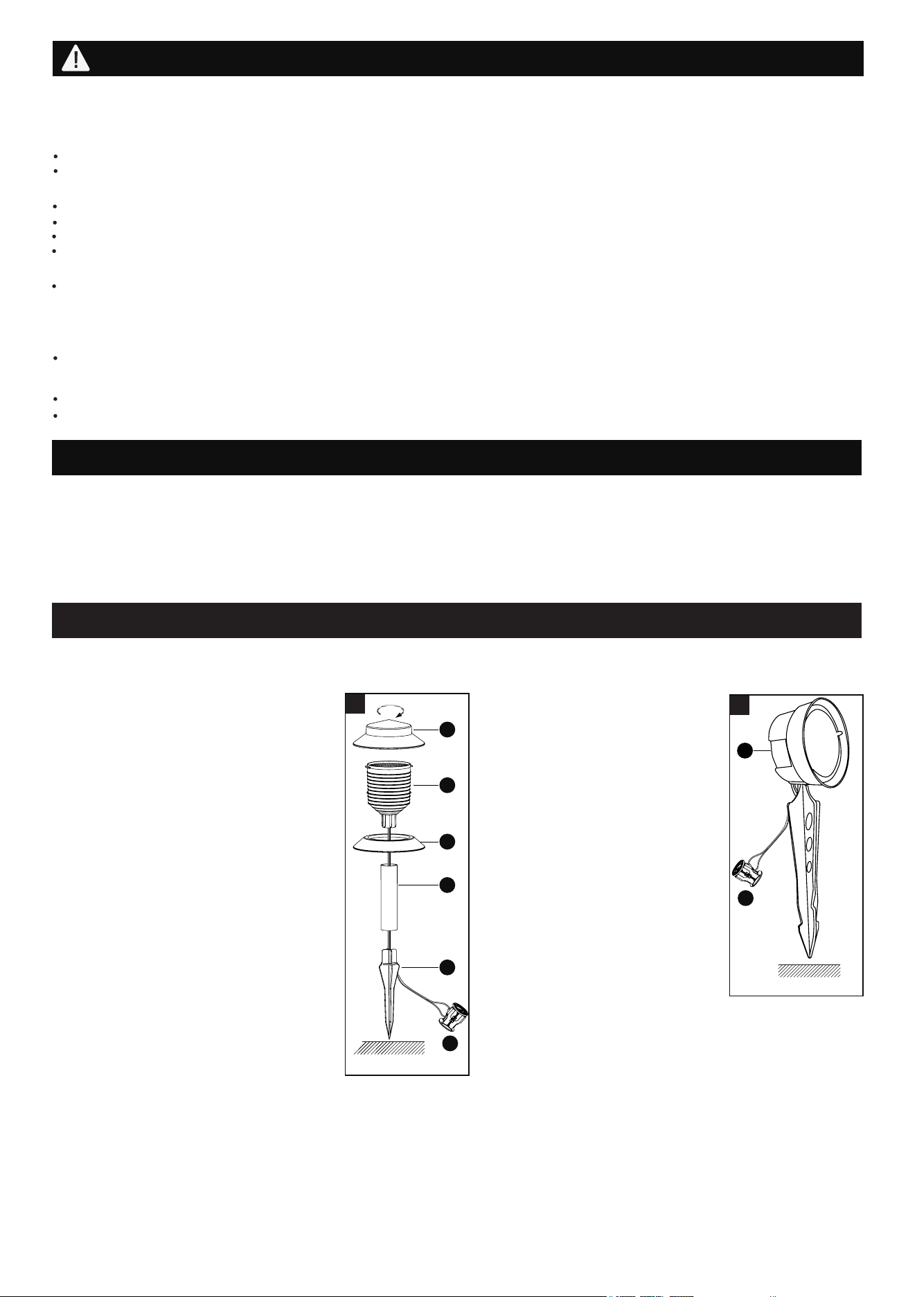
ASSEMBLY INSTRUCTIONS
1.1 Insert ground stake (E) by pressing
it into the tube (D). Install the tube (D)
by pressing it into the lens (B). Snap
the disk (C) into the slot in the lens (B).
Turn the cover (A) on the lens (B) until
it stops. Gently insert the ground
stake (E) into the ground. (Fig.1.1)
Fixture installation
1.2 The flood light is fully assembled.
The lamp body (G) can be rotated
up and down. The lens should be
point up and never towards the
ground. Gently insert the ground
stake into the ground. (Fig.1.2)
Never push the fixture into the
ground by the fixture head.
Note: In compacted, clay, or
hard soils, moisten the ground
with water before inserting the
stake into the ground to avoid
breakage. (Fig.1.1 and Fig.1.2).
1.1
A
Ground
B
C
D
E
F
1.2
G
Ground
Fixture Assembly
F
CAUTION
This lighting fixture is only suitable for a 12V power supply.
Use shielded cable for outdoor use in the following sizes: 18 AWG, 16 AWG, 14 AWG, 12 AWG.
Do not submerge in water.
Do not repair or modify this product.
2.1 Make sure power is turned off.
2.2 The wire connector (F) is intended for use with 18 AWG, 16 AWG, 14 AWG or 12 AWG outdoor cables.
Page 3 of 6
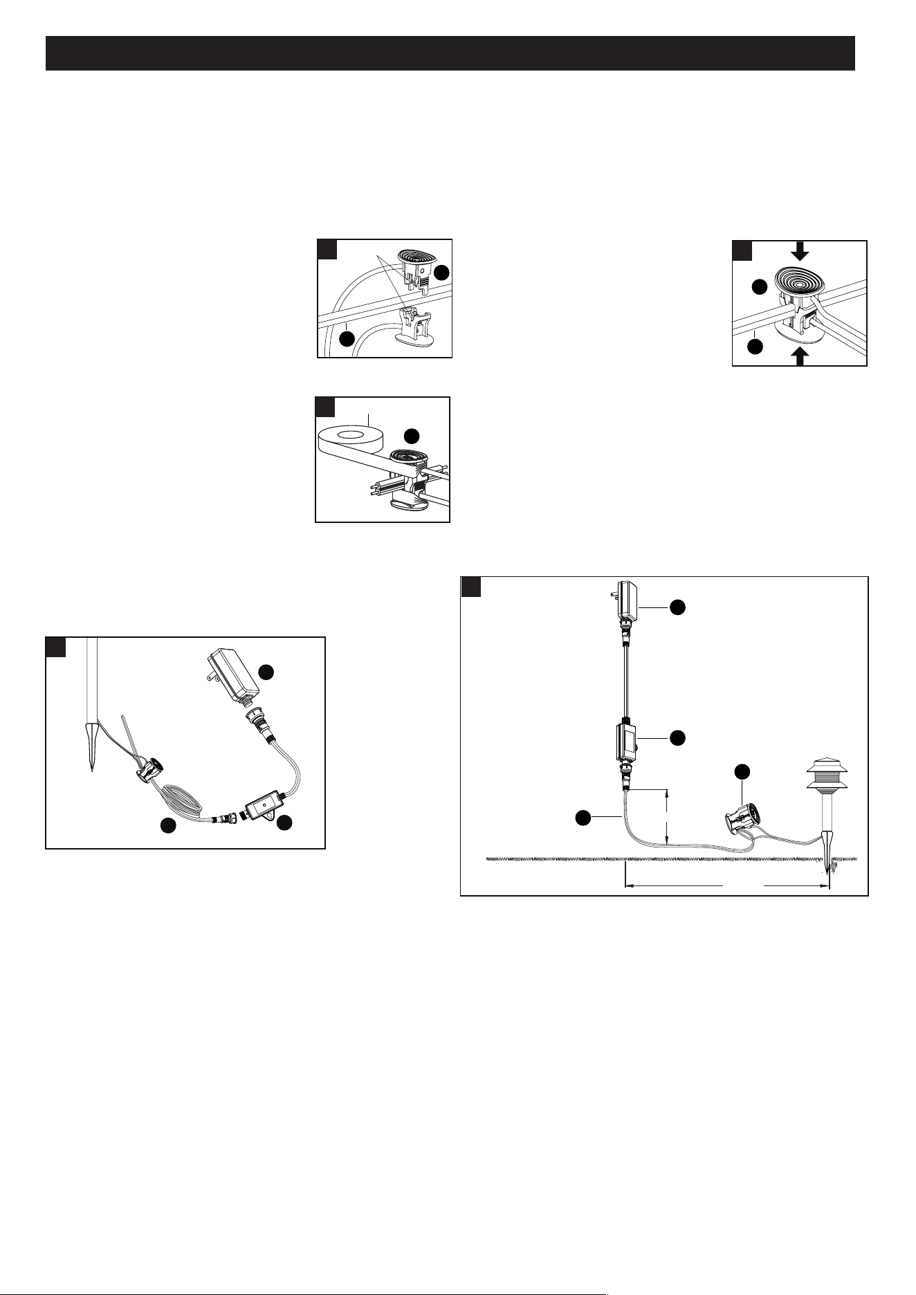
3. Connect the female terminal from the
power cable (I) to male terminal from the
photocell (J). And then connect the
female terminal from the photocell (J)
to the male terminal from the transformer (H).
Finally plug the transformer (H) into the proper
electrical outlet. (Fig.3)
NOTE: Power Cable (I) :18AWG 50'
length; Transformer (H): 24W
4. Attach the fixture to the power cable (I) with the wire
connector (F). To insure uniform brightness the first
fixture should be a minimum of 10 feet (3 meters) from
the transformer (H). (Fig.4)
ASSEMBLY INSTRUCTIONS (continued)
221024
2.3 Place the wire connector (F) on
opposite sides of the power
cable (I) where the fixture will be
located. Align and fit the power
cable (I) vertically in the slot of wire
connector (F) as shown. (Fig.2.3)
Contact Pin
2.3
F
I
2.4 Press the wire connector (F)
together until fully seated and
locked around the power cable (I).
Pre-set prongs will pierce the
power cable (I) insulation and
establish contact. Turn on the
power unit. If the light fixture does
not turn on, repeat operations
2.3 and 2.4. (Fig.2.4)
2.5 Once the wire connector (F) is in
place, wrap it with electrical tape
for additional protection. (Fig.2.5)
2.4
F
F
2.5
Wire Connector wiring instructions
4
12"(30cm)
10 ft. (3m)
3
I
J
H
H
J
I
F
I
Electrical Tape
Page 4 of 6
Caution:
a. The included wire connectors are to be used only on low voltage power cable with 18 AWG, 16 AWG, 14 AWG or
12 AWG cable.
b. The fixture's cable and wire connector shall:
● Be protected by routing in close proximity to the light fixture, or next to a building structure such as a house or deck.
● Not be buried except for a maximum 6 inches (15.2 cm) to connect to the power cable.
● Have a length such that the connector is within 6 inches (15.2 cm) from the light fixture or a building structure.
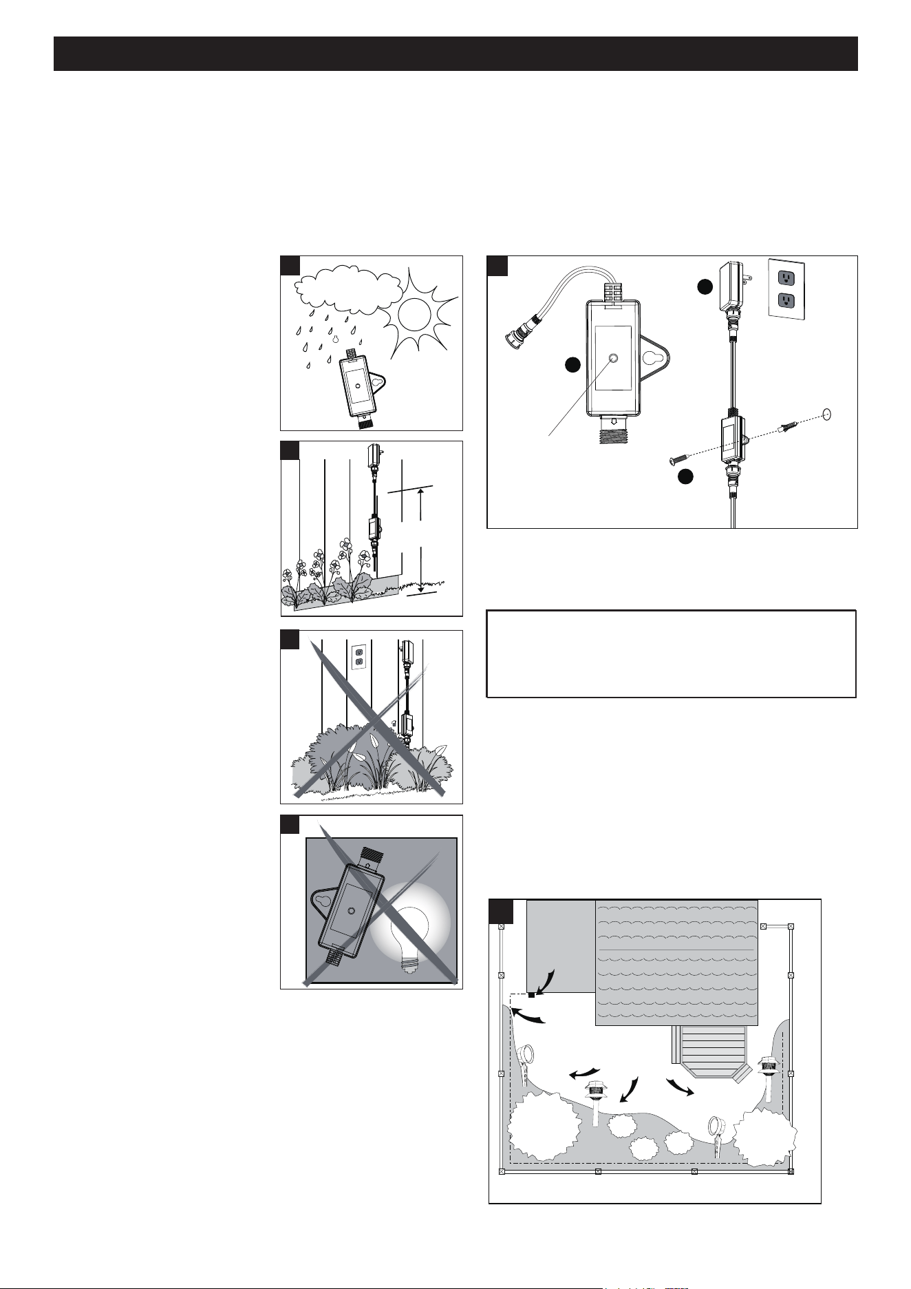
5.1
5.2
5.3
5.4
5.1 Outdoor use, weatherproof.
5.2 Install the transformer (H) at
level where the controls are
visible and accessible.
6. Install the photocell (J) with a screw and an anchor (K)
in a wall near an electrical outlet and mount the
transformer (H).
Photocell
5.3 Do not install behind shrubs.
It will affect photocell .
5.4 Photocell (J) will not operate
properly if installed too
close to a nighttime light
source.
5. Find a location for transformer and photocell: 6. Mount the transformer and photocell:
6
7. Run The Power Cable (included)
Safe
from 12” to 48”
(30cm to 121cm)
Photocell:
IMPORTANT:
The sensor has an excellent photocell function
to enable the light to turn on at dusk and off at
dawn automatically.
This photocell reacts to light conditions. It should not
have direct contact with any other light sources. A 8
second delay may be experienced when light conditions
change. To test the system during the daytime, simply
cover the photocell with black tape.
Optional Installation: Disconnect Photocell
The photocell (J) can be disconnected if not needed.
Directly connect the female terminal from the power
cable (I) to the male terminal from the transformer (H).
ASSEMBLY INSTRUCTIONS (continued)
221024
Power
Cable
Fixtures
7
* Illustration of fixtures is for example only.
Transformer
H
J
K
Page 5 of 6
7. The power cable (I) should run from the transformer to each light without being cut. Do not run the power cable (I)
within 10 feet (3m) of a pool, spa or fountain. If the power cable (I) is too long, cut it with a cable cutter.
The power cable (I) should be protected by routing it close to proximity of the light fixture or next to a building, deck
or fence. Use the power cable included in this kit. For uniform brightness and longer bulb life, attach first fixture at
least 10 feet from transformer.
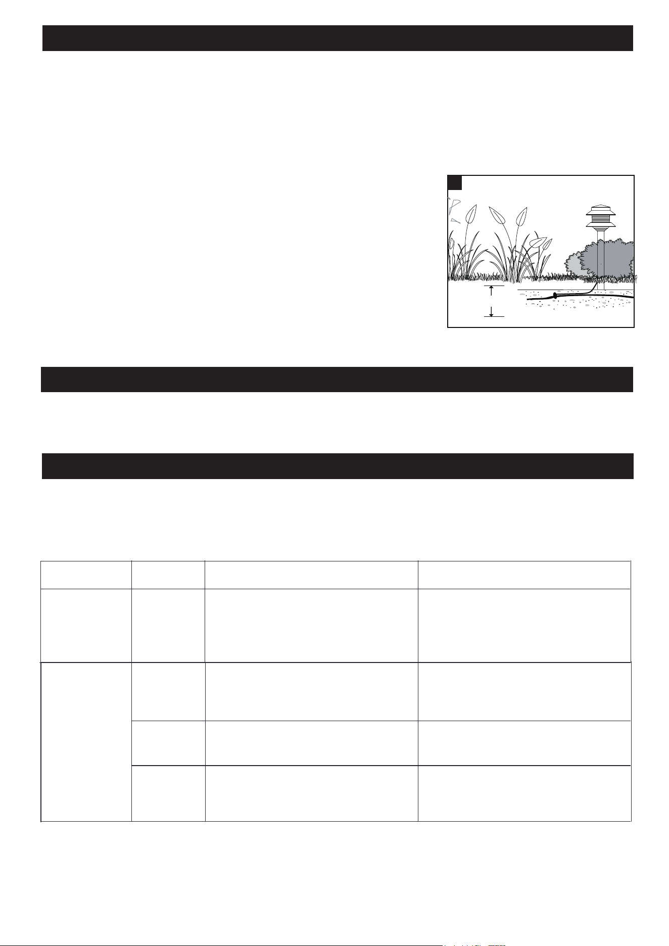
8. Bury the power cable
PLEASE NOTE: This garden light system must be installed in accordance with all local
codes and ordinances. If you are experiencing problems, contact a qualified electrician.
TROUBLESHOOTING
CARE AND MAINTENANCE
Clean the lens and surfaces with a non-abrasive cleaner. Do not use any cleaners with chemicals, solvents or harsh
abrasives. Use only a soft dry cloth to dust or wipe the lens area.
If all the light does not work.
1. Check that the transformer power is on.
2. Check if there is a loose connection at the transformer screw terminal.
3. Check that the control switch is not in the OFF setting.
ASSEMBLY INSTRUCTIONS (continued)
8. The power cable (I) and wire connector (F) can also be hidden under mulch,
stone or buried under grass at a maximum depth of 6" (15.2cm).
8
6" (15.2cm) max.
*
Illustration of fixture is for example only.
221024
If the light
isn’t on
It is suggested to only use 8 path
lights + 2 spot lights.
Re-confirm that the metal contact pins
have pierced the power cable, and
ensure the wiring is connected well.
You can cover the sensor by hand. Once
the light is on, you can change the
location. Keep away from the light glaring.
Poor contact of the wire connector.
Exceeding the rated current of the power
supply, causing overload and the light is
off.
It is installed where there is strong light.
Day and night
Day and night
Night
Symptom
If the light
isn’t on
Day / Night
Day
PHOTOCELL sensor is exposed to
bright light.
For the first installation during the day, it's
necessary to test the sensor function by
hand covering.
Possible Cause Solution
Page 6 of 6
If unable to fix any of the above issues, please consult a certified electrician.
221024
If only some of
the lights are on
or flash.
If the light stays
on
1. Remove the wire connector and visually
inspect the metal contact pins and
ensure the metal contact pins pierce
the insulation on the power cable from
the transformer.
2. Make sure you are using less than
24 watts. If necessary, remove the
unlit light.
If the light turns off after a strong light is
shined on the photocell sensor after a
few minutes, it is operating normally.
Just need to relocate fixture.
1. Poor contact of the wire connector.
2. Exceeding the rated current of the
power supply, causing an overload to
occur which causes the light to shut
off.
The fixture may be installed in a shady
area.
Day
Day and night
Symptom
Day / Night
Possible Cause Solution
TROUBLESHOOTING (continued)
FIVE-YEAR LIMITED WARRANTY: If, during normal use, this PATRIOT LIGHTING lighting fixture breaks or fails
due to a defect in material workmanship within five (5) years from the date of original purchase, simply bring this
lighting fixture with the original sales receipt back to your nearest MENARDS retail store. At its discretion, PATRIOT
LIGHTING agrees to have the product or any defective part(s) repaired or replaced with the same or similar PATRIOT
LIGHTING product or part free of charge, within the stated warranty period, when returned by the original purchaser
with original sales receipt. This warranty; (1) excludes expendable parts including but not limited to light bulbs; (2) does
not cover damage that has resulted from abuse or misuse; and (3) does not cover any losses, labor, injuries to
persons/property or costs. This warranty does give you specific legal rights and you may have other rights, which vary
from state to state.
R
R
R
R
Questions, problems, missing parts?
Before returning to your retailer, call our customer service at 1-800-887-6326
Monday – Friday 9:00 a.m. – 5:00 p.m. CST