NOTE: Spring Pin (21)
and Switch Paddle (24)
must be removed in
order to access Screw
(18). See additional
note below.
18
21
24
25
NOTE: Replace 16
whenever handle
halves are removed
1a
1b
1c
7
8(3x)
10
9
103
2
3
4
102
6
13
22
19
15
104
24
23
20
21
14
17
18(5x)
16(4x)
16 17 18
19 20 21
105
7 8
9 10
106
1a 1b
1c
28
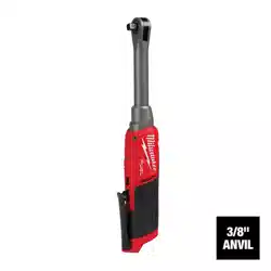
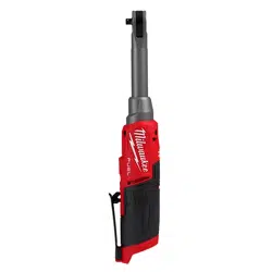
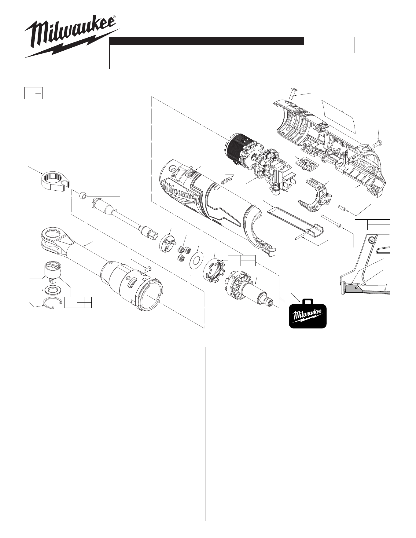
2568-20
M12™ FUEL 1/4" LONG REACH RATCHET
Nov. 2022
FIG. PART NO. DESCRIPTION OF PART NO. REQ.
1a --------------- 1/4" Anvil (1)
1b --------------- Friction Plate (1)
1c --------------- Retaining Ring (1)
2 45-98-0020 Yoke (for 1/4" ratchet) (1)
3 42-40-0017 Bushing (for 1/4" ratchet) (1)
4 36-17-0016 Crank Shaft (for 1/4" ratchet) (1)
6 44-60-0890 Drive Pin (1)
7 28-23-1010 Carrier (1)
8 32-62-0085 Planet Gear (for 1/4" ratchet) (3)
9 32-64-0130 Ring Gear (for 1/4" ratchet) (1)
10 05-90-0230 Washer (1)
13 44-66-1006 Motor Plate (1)
14 05-84-0205 M2.5 Screw (3)
15 06-82-2310 M3 x 8mm Pan Hd. T-10 Screw (1)
16 05-81-0594 M4 Flat Hd. T-20 Screw (4)
17 12-20-0461 Service Nameplate (1)
18 05-71-0017 M4 x 10mm Pan Hd. T-20 Screw (5)
19 --------------- Housing Cover - Right Housing Halve (1)
20 --------------- Housing Support - Left Housing Halve (1)
21 44-60-0575 Rivet Pin (1)
22 42-42-0119 Switch Lock-Out (1)
23 10-20-7229 Fuel Gauge Label (1)
24 44-10-0740 Switch Paddle (1)
25 42-55-2559 Zippered Tool Case (1)
26 49-16-2569 Rubber Boot (Optional, Acc) (Not Shown) (1)
28 42-06-0146 1/4" Anvil Service Kit (1)
102 14-30-0446 1/4" Yoke / Beam / Gearcase Service Assy (1)
103 16-01-2560 Rotor Service Assembly (for 1/4" ratchet) (1)
104 14-20-2561 Electronics Service Assembly (1)
105 14-38-0505 Housing Service Kit (1)
106 28-23-2500 Gear Set Service Kit (1)
54-47-0430
REVISED BULLETIN
SERVICE PARTS LIST
BULLETIN NO.
WIRING INSTRUCTION
DATE
CATALOG NO.
SPECIFY CATALOG NO. AND SERIAL NO. WHEN ORDERING PARTS
SERIAL
NUMBER
EXAMPLE:
Component Parts
(Small #) Are Included
When Ordering Assy.
(Large #).
0
00
N27A
See Pages 2 and 3
FIG. NOTES
17,19 Prior to installing a new service nameplate, apply isopropyl
alcohol to the handle cover with a clean, lint free applicator
and allowed to dry.
21 Use a thin blunt punch with the same OD or a similiar tool like
anishingnailwiththesameODandthepointedtipground
down to remove spring pin from the handle halves and switch
paddle. As an aid, be sure to prop up that corner end of
ratchet to support the tapping out of the spring pin. When
reinstalling pin, align the holes and carefully press or tap the
pin in place.
MILWAUKEE TOOL
l
www.milwaukeetool.com
13135W.LisbonRoad,Brookeld,WI53005
Drwg. 2
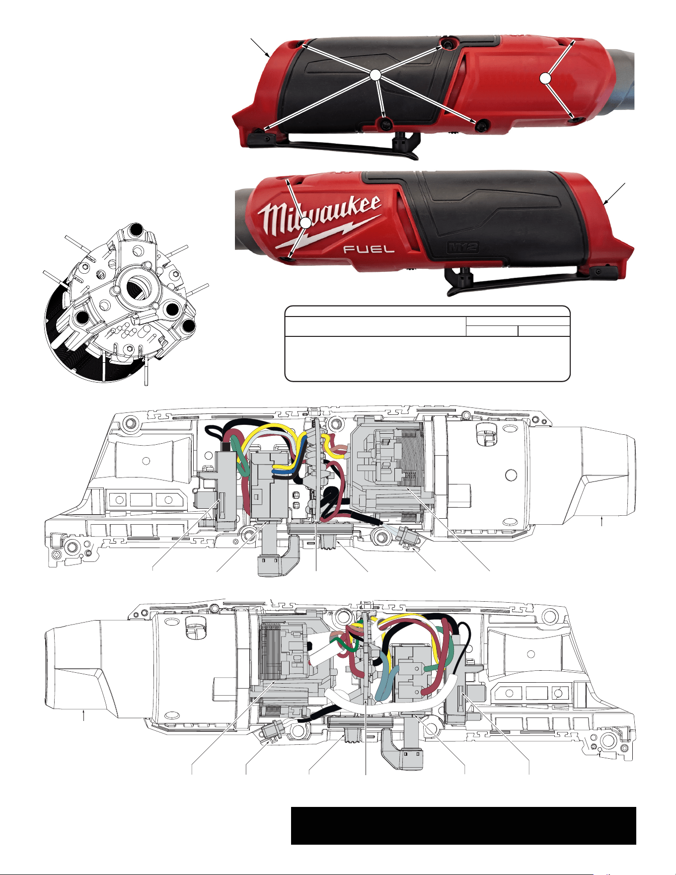
Battery
Terminal Block
RIGHT SIDE
VIEW
LEFT SIDE
VIEW
On/Off
Switch
PCBA
Board
LED
Lens
Switch
Lock Out
Stator
Battery
Terminal Block
On/Off
Switch
PCBA
Board
LED
Lens
Switch
Lock Out
Stator
Yoke housing
assembly
Yoke housing
assembly
16
20
16
19
NOTE:
Wires of the electronics assembly (104) are
routed in traps and cavities in the right handle
halve (19).
To replace the Electronics Assembly (104):
Remove five T-10 handle screws (18) from
right handle halve (19) and two T-10
handle/gear case screws (16) from right
handle halve.
Gently turn tool over and remove two T-10
handle/gear case screws (16) from left handle
halve.
Carefully remove the left handle halve to
expose the electronics assembly.
Use a hex key to remove the three socket
head screws (14) and slide stator/rotor/motor
mount plate out of yoke housing assembly
(31).
18
SEE NEXT PAGE FOR SERVICE INSTRUCTIONS
TO AID WITH THE REMOVAL AND INSTALLATION
OF ELECTRONICS ASSEMBLY (104).
Battery
Terminal Block
RIGHT SIDE
VIEW
LEFT SIDE
VIEW
On/Off
Switch
PCBA
Board
LED
Lens
Switch
Lock Out
Stator
Battery
Terminal Block
On/Off
Switch
PCBA
Board
LED
Lens
Switch
Lock Out
Stator
Yoke housing
assembly
Yoke housing
assembly
16
20
16
19
NOTE:
Wires of the electronics assembly (104) are
routed in traps and cavities in the right handle
halve (19).
To replace the Electronics Assembly (104):
Remove five T-10 handle screws (18) from
right handle halve (19) and two T-10
handle/gear case screws (16) from right
handle halve.
Gently turn tool over and remove two T-10
handle/gear case screws (16) from left handle
halve.
Carefully remove the left handle halve to
expose the electronics assembly.
Use a hex key to remove the three socket
head screws (14) and slide stator/rotor/motor
mount plate out of yoke housing assembly
(31).
18
SEE NEXT PAGE FOR SERVICE INSTRUCTIONS
TO AID WITH THE REMOVAL AND INSTALLATION
OF ELECTRONICS ASSEMBLY (104).
SCREW TORQUE SPECIFICATIONS
SEAT TORQUE
FIG. PART NO. WHERE USED (KG/CM) (IN/LBS)
14 05-84-0205 Motor Plate 5-7 4-6
15 06-82-2310 Electronics Assy. 12-14 10-12
16 -------------- Housing Halves 17-21 15-18
18 -------------- Housing Halves 10-12 9-10
15
14
14
14
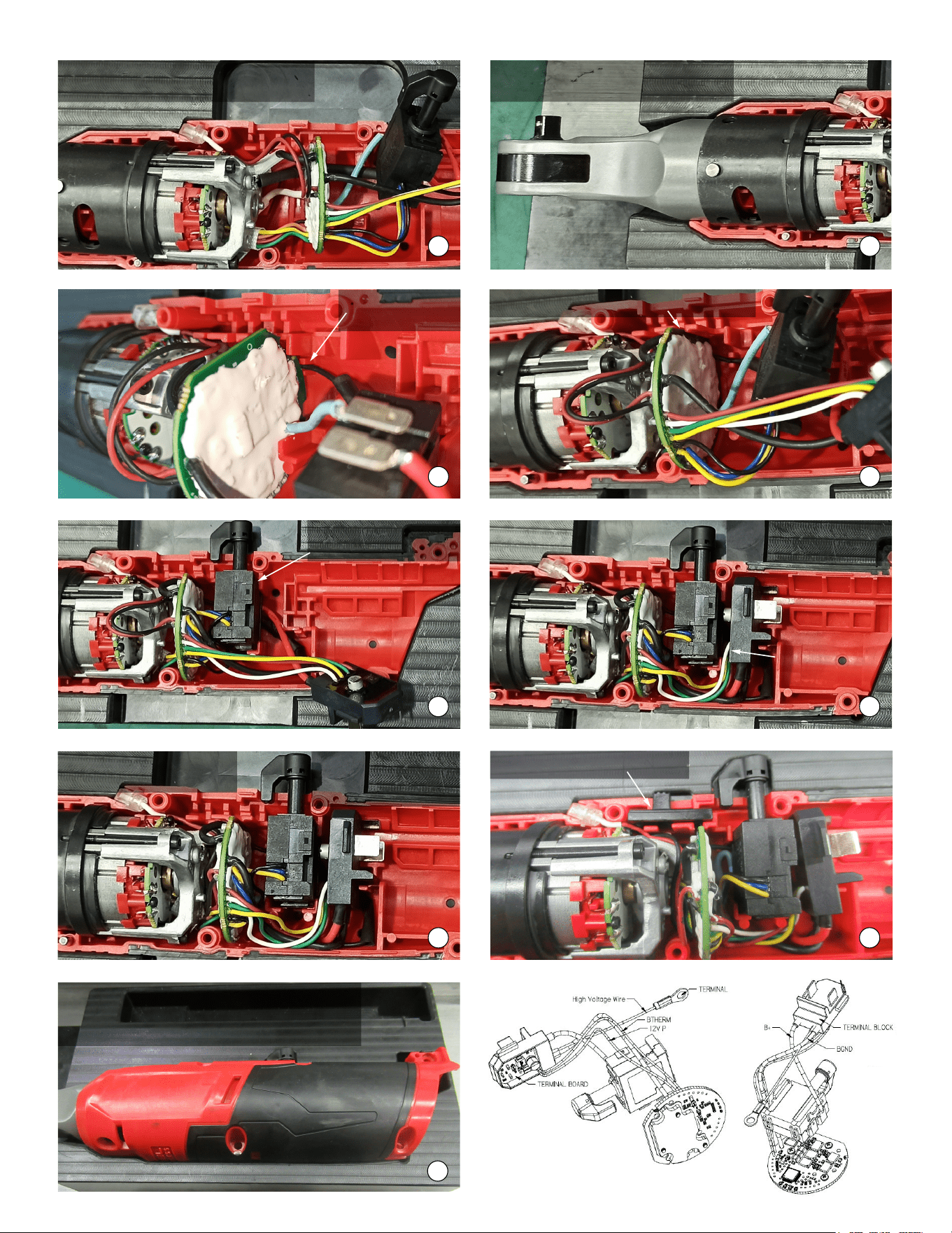
Install yoke assembly onto
housing support/electronics assembly.
Place the HV wire
into wite trap.
Assemble control board into housing slot.
Assemble on-off switch
into housing cavity.
Place battery terminal
block into housing cavity.
Push all wires down into
housing cavities as shown.
Install the switch lock-out slideBe sure that all
components are firmly
and squarely in place.
PRIOR TO INSTALLING THE HOUSING COVER
ONTO THE HOUSING SUPPORT, BE SURE THAT
THERE ARE NO INTERFERENCES.
Place electronics assembly into housing
support. Install LED lens as shown.
1 2
3 4
5 6
7
8
9
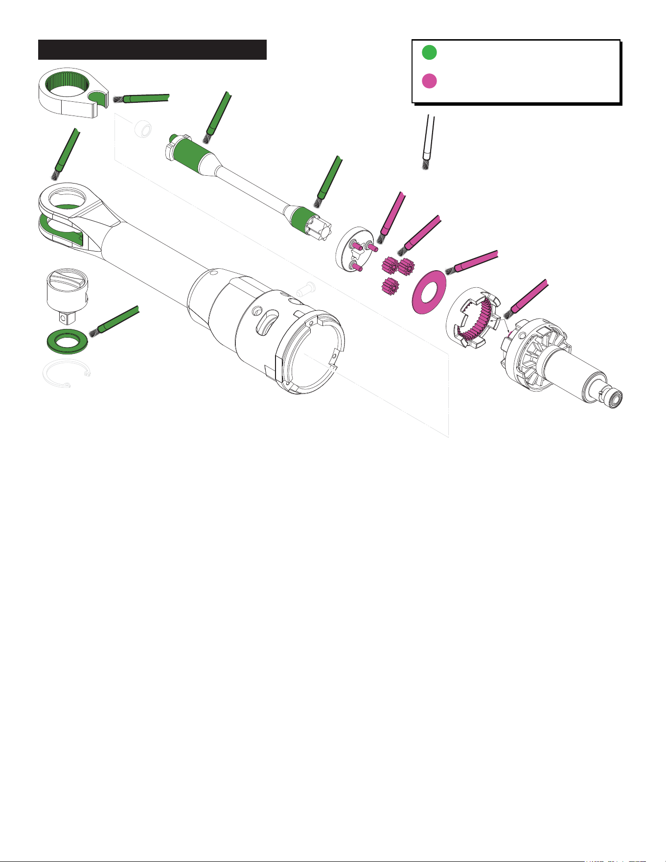
NOTE
When servicing, remove 90-95% of the existing
grease prior to installing grease. Clean gear
assemblies with a clean, dry cloth.
Apply a liberal amount of grease to all areas
indicated. Be sure all teeth of gears, inside
diameter gear teeth of the ring gear and the
teeth of the motor pinion are completely coated.
Internal components of the anvil assemblies
should come from the factory pre-lubricated.
DECH 5166 Grease, No. 49-08-0018
(26-oz., 0.8kg plastic tub)
DECH 5157 Grease, No. 49-08-0016
(26-oz., 0.8kg plastic tub)
LUBRICATION INSTRUCTIONS