
2556-20
M12™ FUEL 1/4" RATCHET
Aug. 2021
FIG. PART NO. DESCRIPTION OF PART NO. REQ.
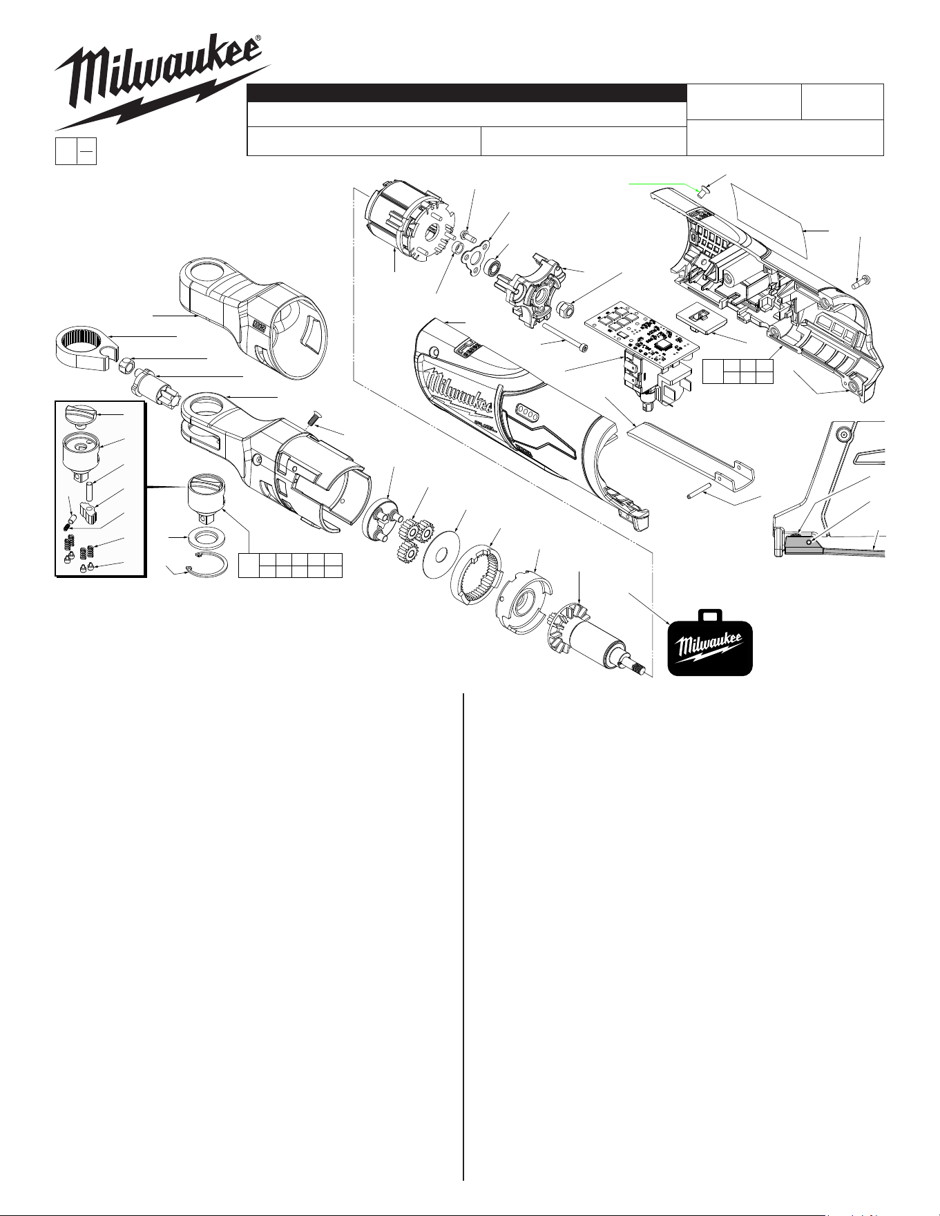
1 42-06-2556 1/4" Anvil Service Kit (1)
1a --------------- Forward/Reverse Knob (1)
1b --------------- 1/4" Anvil (1)
1c --------------- Pawl Pin (1)
1d --------------- Pawl (1)
1e --------------- Cap (1)
1f --------------- Spring (1)
1g --------------- Spring (4)
1h --------------- Spring Pin (4)
1j --------------- Friction Plate (1)
1k --------------- Retaining Ring (1)
2 45-98-0060 Yoke (for 1/4" ratchet) (1)
4 42-40-0975 Bushing (for 1/4" ratchet) (1)
5 36-17-0400 Crank Shaft (for 1/4" ratchet) (1)
6 28-23-1000 Carrier Assembly (for 1/4" ratchet) (1)
7 32-62-0610 Planet Gear (for 1/4" ratchet) (3)
8 45-88-2035 Washer (1)
9 32-65-0400 Ring Gear (for 1/4" ratchet) (1)
10 44-66-0047 Motor Holder (1)
11 05-81-0105 M3 x 10mm Flat Hd. Machine T-10 Screw (3)
14 42-40-0210 Bushing (1)
15 06-82-2310 M3 x 8mm Pan Hd. Tapt. T-10 Screw (3)
16 44-86-1405 Bearing Plate (1)
17 02-04-0307 Ball Bearing (1)
18 44-66-1007 Motor Plate (1)
19 05-84-0200 M2.5 x 31mm Socket Head Hex Screw (3)
20 05-55-0047 Hex Nut (1)
21 05-81-0592 M4 x 6mm Flat Hd. T-15 Machine Screw (4)
22 06-82-3002 M3 x 10mm Pan Hd. Tapt. T-10 Screw (4)
23 --------------- Housing Cover - Right Housing Halve (1)
24 --------------- Housing Support - Left Housing Halve (1)
25 44-60-0575 Spring Pin (1)
26 44-10-0740 Switch Paddle (1)
27 42-42-0033 Switch Lock-Out (1)
30 31-44-0522 Housing Kit (1)
31 14-46-0472 1/4" Yoke Housing Assembly (1)
32 14-20-0107 Electronics Assy. (for 1/4" & 3/8" ratchet) (1)
33 16-01-1025 Rotor Assembly (for 1/4" ratchet) (1)
34 12-20-2556 Service Nameplate (1)
54-47-0441
REVISED BULLETIN
SERVICE PARTS
BULLETIN NO.
WIRING INSTRUCTION
DATE
CATALOG NO.
SPECIFY CATALOG NO. AND SERIAL NO. WHEN ORDERING PARTS
SERIAL
NUMBER
EXAMPLE:
Component Parts
(Small #) Are Included
When Ordering Assy.
(Large #).
0
00
J18B
54-47-0440
See Pages 2 and 3
FIG. PART NO. DESCRIPTION OF PART NO. REQ.
35 42-55-0300 Zippered Tool Case (1)
36 42-04-0805 1/4" to 3/8" Adapter (Not Shown) (1)
37 49-16-2556 Rubber Boot (Optional, Accessory) (1)
FIG. NOTES
23,34 Prior to installing a new service nameplate, apply isopropyl
alcohol to the handle cover with a clean, lint free applicator
and allowed to dry.
25 Use a thin blunt punch with the same OD or a similiar tool like
anishingnailwiththesameODandthepointedtipground
down to remove spring pin from the handle halves and switch
paddle. As an aid, be sure to prop up that corner end of
ratchet to support the tapping out of the spring pin. When
reinstalling pin, align the holes and carefully press or tap the
pin in place.
FIG. LUBRICATION
(Type 'E' Grease, No. 49-08-4122):
5 Apply a moderate coating of grease to the small cylindrical
surface that goes into driver bushing and to the large cylindri-
cal surface that is surrounded by the two needle bearings.
6 Apply a moderate coating of grease to the three axles of the
carrier assembly prior to installing the planet gears.
8 Apply a light coat of grease to the surface of the washer.
9,33 Apply a heavy coating of grease to the inside diameter gear
teeth of the ring gear and the teeth of the motor pinion.
MILWAUKEE TOOL
l
www.milwaukeetool.com
13135 W. LISBON RD., BROOKFIELD, WI 53005
Drwg. 2
1a
1b
1c
1d
1f
1g
1h
1e
1j
1k
1a 1b 1c 1d 1e
1f 1g 1h 1j 1k
1
2
4
5
31
11(3x)
6
7(3x)
8
9
10
33
15(3x)
16
17
18 20
27
23
32
19(3x)
26
24
14
32
25
34 22(4x)
21(4x)
21 22 23
24 25 34
30
NOTE: Spring Pin (25)
and Switch Paddle (26)
must be removed in
order to access Screw
(22). See additional
note below.
22
25
26
35
37
NOTE: Replace 21
whenever handle
halves are removed
NOTE: Add a drop of
Red Loctite 263 to
the threads of four
screws (21). Clean
threaded holes of any
old Loctite prior to installing.
= Part number change from
previous service parts list.
22 21
23
21
24
23
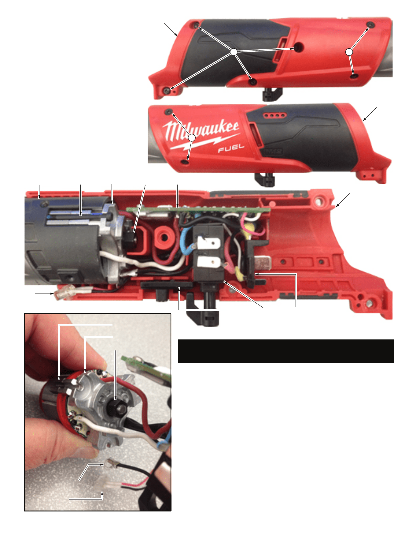
NOTE:
Wires of the electronics assembly (32) are
routed in traps and cavities in the right handle
halve (23).
To replace the Electronics Assembly (32):
Remove four T-10 handle screws (22) from right
handle halve (23) and two T-10 handle/gear
case screws (21) from right handle halve.
Gently turn tool over and remove two T-10
handle/gear case screws (21) from left handle
halve.
Carefully remove the left handle halve to expose
the electronics assembly.
Use a hex key to remove the three socket head
screws (19) and slide stator/rotor/motor mount
plate out of yoke housing assembly (31).
Rotor assembly (33) must be removed from the
stator by securing the rotor fan and unscrewing
the hex nut (20) outside of motor plate (18).
SEE NEXT PAGE FOR SERVICE INSTRUCTIONS
TO AID WITH THE REMOVAL AND INSTALLATION
OF ELECTRONICS ASSEMBLY (32).
Ground wire terminal
LED assembly
Stator
Motor plate (18)
Hex nut (20)
Yoke housing
assembly (31)
Socket head
screws (19)
Hex nut
(20)
Motor plate
(18)
PCBA
LED
On-off
switch
Battery terminal
block
Switch lock
out (27)
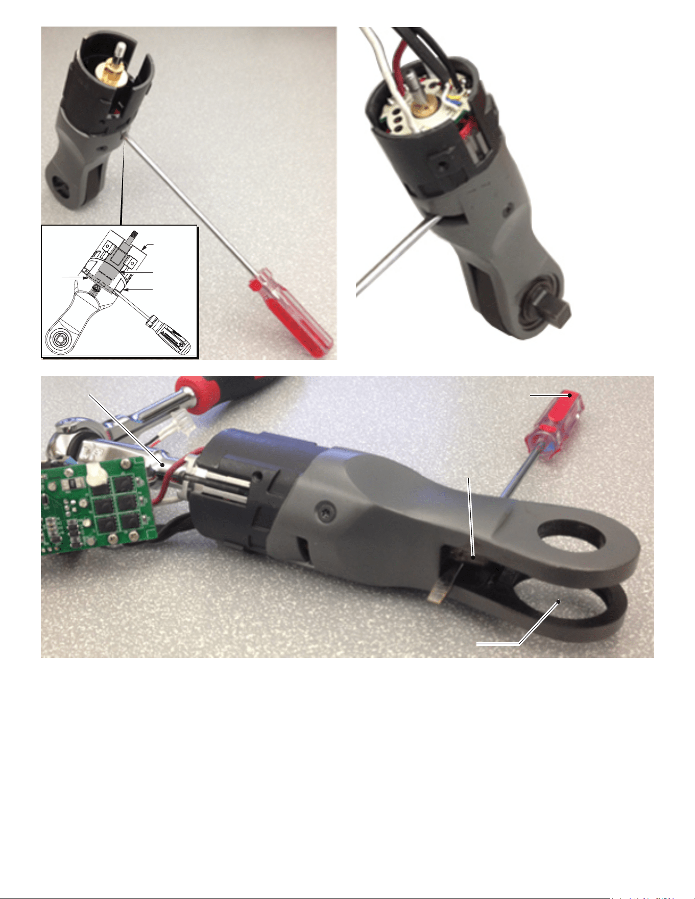
Assemble existing rotor (33) into yoke
housing assembly (31). Engage rotor
pinion with planet gears (7) and seat
rotor bearing in motor holder (10).
NOTE:
It is important to keep the rotor seated
when installing the stator. Magnetism
from the stator WILL pull the rotor out of
position. As an aid to assembly, use a
flat blade screwdriver and place it
through yoke housing air vent so blade is
on top of rotor fan. Place yoke housing
assembly on a level surface and tilt
towards screwdriver to maintain
pressure on rotor fan. Yoke housing
is wide enough to remain
upright with screwdiver in
place, allowing both
hands to be used to
install stator.
Orient stator with red wire to the top of tool. Place
stator assembly into yoke housing and over rotor.
Slide the existing bushing (14) over thread-
ed rotor spindle. Work existing motor
plate/bearing/bearing plate assembly
(15,16,17,18) through stator wires and
over threaded rotor spindle. Slide
the three legs of motor plate into the
corresponding channels of yoke
housing assembly.
Secure motor plate with three
socket head screws (19), being
sure to capture the ground
terminal, positioned at bottom.
Tighten the three screws
uniformally using a 2mm hex
key.
Secure rotor with hex nut
(20) as explained below.
5/16” hex socket
Crank shaft pin
Remove yoke and
anvil assembly so a screwdriver
can be placed under the pin of crank shaft
to lock rotor so hex nut can be tightened.
Screwdriver or similar tool to prevent the rotor
assembly from rotating when tightening hex nut.
NOTE: It is recommended to use the largest
screwdriver/tool possible when performing
this step.
Yoke
housing
Rotor
Air vent
Rotor
fan
To properly tighten hex nut (20) to rotor (33), it is important to lock rotor
and keep it from spinning. The recommended approach is illustrated
above.
With a snap ring pliers, remove snap ring (1k). Carefully remove the
anvil kit (1) being sure to keep the friction plate (1j) pressed against it.
Remove yoke (2) and bushing (4) exposing the ‘pin’ of crank shaft (5).
With a screwdriver or similar tool, slide under crank shaft pin and wedge
between pin and yoke housing, preventing crank shaft and all gearing
(including rotor pinion) from moving. Use a 5/16” socket to secure hex
nut to rotor spindle. Tighten to 33-37 kg-cm (approx. 28-32 in-lbs).
Remove screwdriver and reinstall bushing and yoke onto crank shaft
pin. Carefully place anvil kit and friction plate back into yoke and secure
with snap ring.
Place yoke assembly in right handle halve. Prior to installing switch and
PCBA, place LED assembly in housing halve. Route LED wires and
ground wire through channels and traps, than behind the switch as
shown above. Be sure all wires are pressed down firmly.
Place switch, PCBA and battery terminal block into the handle slots and
cavities. Be sure those components are seated firmly and squarely. Pay
particular attention that excess wires are tucked behind the battery
terminal block and that no wires will interfer with the installation of the
other handle halve.
Install the switch lock-out slide (27). Carefully place the left handle halve
(24) onto the right handle halve. Be sure the handles fit together
properly and secure with screws (21 and 22).
Check for proper functionality of switch and switch lock-out slide. Install
battery to make sure tool runs properly.
Install switch paddle (26) and secure with spring pin (25).
NOTE:
Anvil ass-
embly, yoke
and crankshaft
don’t need to be
installed during this
step.