1
• For Outdoor Use Only (outside
any enclosure).
• This instruction manual
contains important information
necessary for proper assembly
and safe use of this appliance.
• Read and follow all warnings
and instructions before
assembling and using the
appliance.
• Follow all warnings and
instructions when using the
appliance.
• Keep this manual for future
reference.
• If you smell gas:
1. Shut off gas to the appliance.
2. Extinguish any open ames.
3. Open the lid.
4. If the odor continues, keep
away from the appliance and
immediately call your re
department.
• Do not store or use gasoline
or other ammable liquids or
vapors in the vicinity of this or
any other appliance.
• An LP cylinder not connected
for use shall not be stored in
the vicinity of this or any other
appliance.
DANGER
WARNING
MODEL NO: CGG-9020
28” Outdoor Griddler -
2-in-1 Griddle & Broiler
DO NOT RETURN PRODUCT TO THE STORE
Before visiting your local retailer, please email outdoors@
cuisinart.com or call our customer service department at
1-866-994-6390 to chat with a representative. To best serve
you, our representatvies are available to answer calls Monday
to Friday 9 AM to 5 PM EST.
Customer Service Hotline
1-866-994-6390
ANSI Z21.58-2018 • CSA 1.6-2018

2
Table of Contents
Table of Contents 2
Safety Information 3
What’s In The Box 5
Assembly Instructions 6
Setup Instructions 28
Operating Instructions for Griddler 30
Care and Maintenance 32
Match Light Instructions 38
Trouble Shooting 39
Exploded View & Parts List 41
Warranty & Replacement Parts Back Cover
3
SAFETY INFORMATION
• The installation must conform with local codes or, in the absence of local codes either ANSI Z223.1/NFPA 54, CSA
B149.1, or CSA B149.2
• This outdoor cooking gas appliance must only be used outdoors and must not be used in a building, garage, or any other
enclosed area
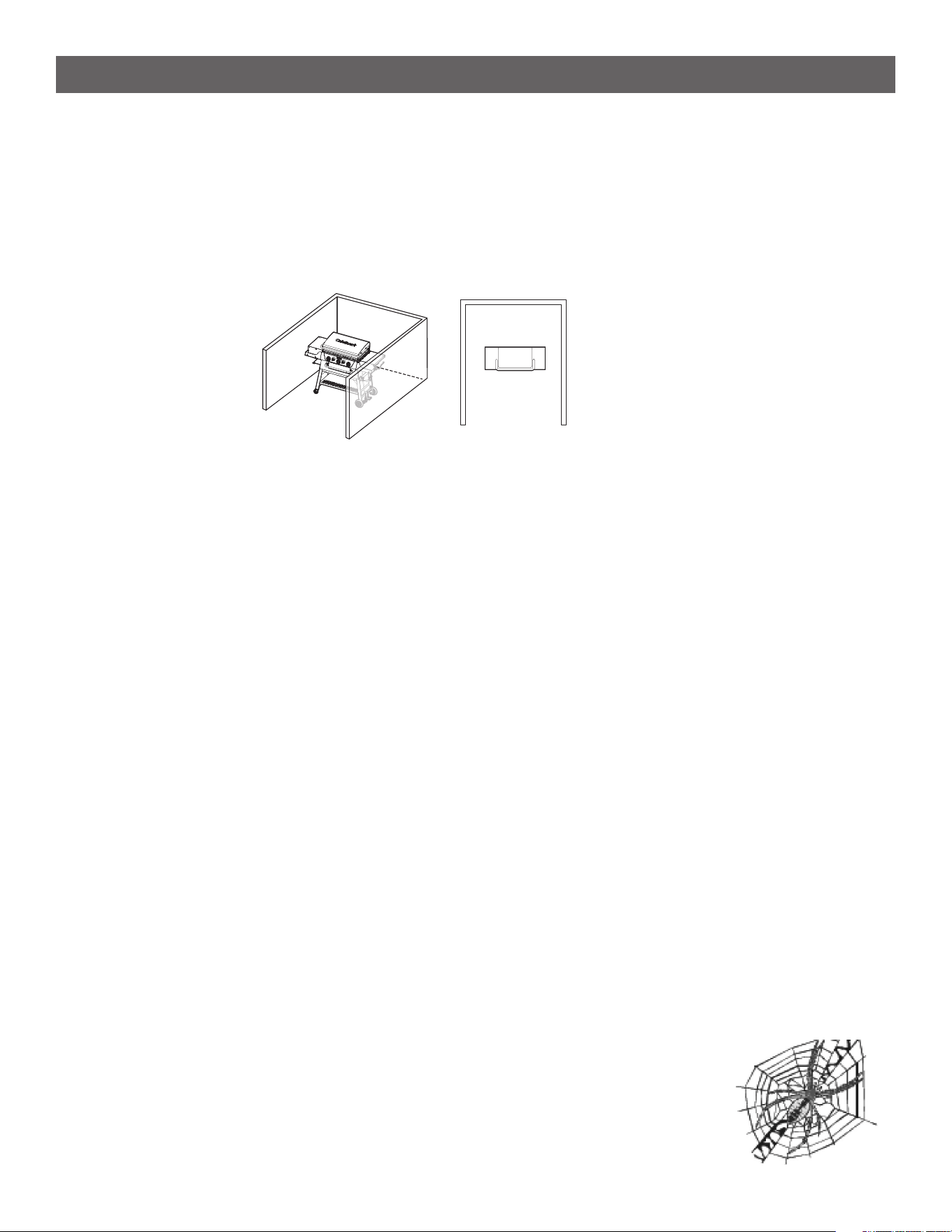
• An appliance is considered to be outdoors if installed with shelter no more inclusive than with walls on three sides, but
with no overhead cover; all openings must be permanently open; sliding doors, garage doors, windows, or screened
openings are not considered as permanent openings.
• This outdoor cooking gas appliance is not intended to be installed in or on boats or on recreational vehicles.
• A minimum clearance of 36 inches from combustible constructions to the sides of the griddle and 36 inches from the
back of the griddle to combustible constructions must be maintained.
• Do not use this appliance under an overhead combustible construction.
• Inspect the hose before each use of the outdoor cooking gas appliance. If it is evident that there is excessive abrasion or
wear, or the hose is cut, it shall be replaced prior to the outdoor cooking gas appliance being put into operation. Please
use the contact information on the front cover to reach our customer service team for any replacement parts.
• Keep any electrical supply cord and the fuel supply hose away from any heated surfaces.
• Keep the outdoor cooking gas appliance area clear and free from combustible materials, gasoline, and other ammable
vapours and liquids.
• Do not obstruct the ow of combustion and ventilation air around the burner box.
• Keep the ventilation openings of the cylinder enclosure free and clear from debris.
• Do not use the griddle unless it is COMPLETELY assembled, and all parts are securely fastened and tightened.
• After a period of storage and/or nonuse, check for leaks, burner obstructions and inspect for any abrasion, wear, cuts to
the hose.
• This appliance is not intended for commercial use.
• The use of alcohol, prescription, or non-prescription drugs may impair the consumer’s ability to properly assemble or
safely operate the appliance.
• When cooking with oil or grease, have a type BC or ABC re extinguisher readily available.
• Do not move the appliance when in use. Allow the cooking vessel to cool to 115°F (45 °C) before moving or storing.
• Do not store a spare LP gas cylinder under or near this appliance.
• Never ll the cylinder beyond 80 percent capacity.
• If these instructions are not followed exactly, a re causing death or serious injury may occur.
NATURAL HAZARD • SPIDERS
FACT: Sometimes spiders and other small insects climb into the burner tube. The spiders spin webs, build nests and lay eggs.
The webs or nests can be very small, but they are very strong and can block the ow of gas. Clean
burner prior to use after storing, at the beginning of outdoor cooking season or after a period of one
month not being used.
SAVE THESE INSTRUCTIONS
FOR OUTDOOR HOUSEHOLD USE ONLY
4
SAFETY INFORMATION
The Fuel System
• Gas appliances are used safely by millions of people when following simple safety precautions. This appliance is
congured for liquid propane, do not use a natural gas supply.
• The components in the fuel system including the pressure regulator and hose are designed for operation with
this Griddle/Broiler. They must not be modied or replaced by components from other brands. (See replacement
parts list on page XX for manufacturer approved components.)
Total gas consumption when set to “High”: 50,000 BTU/Hr.
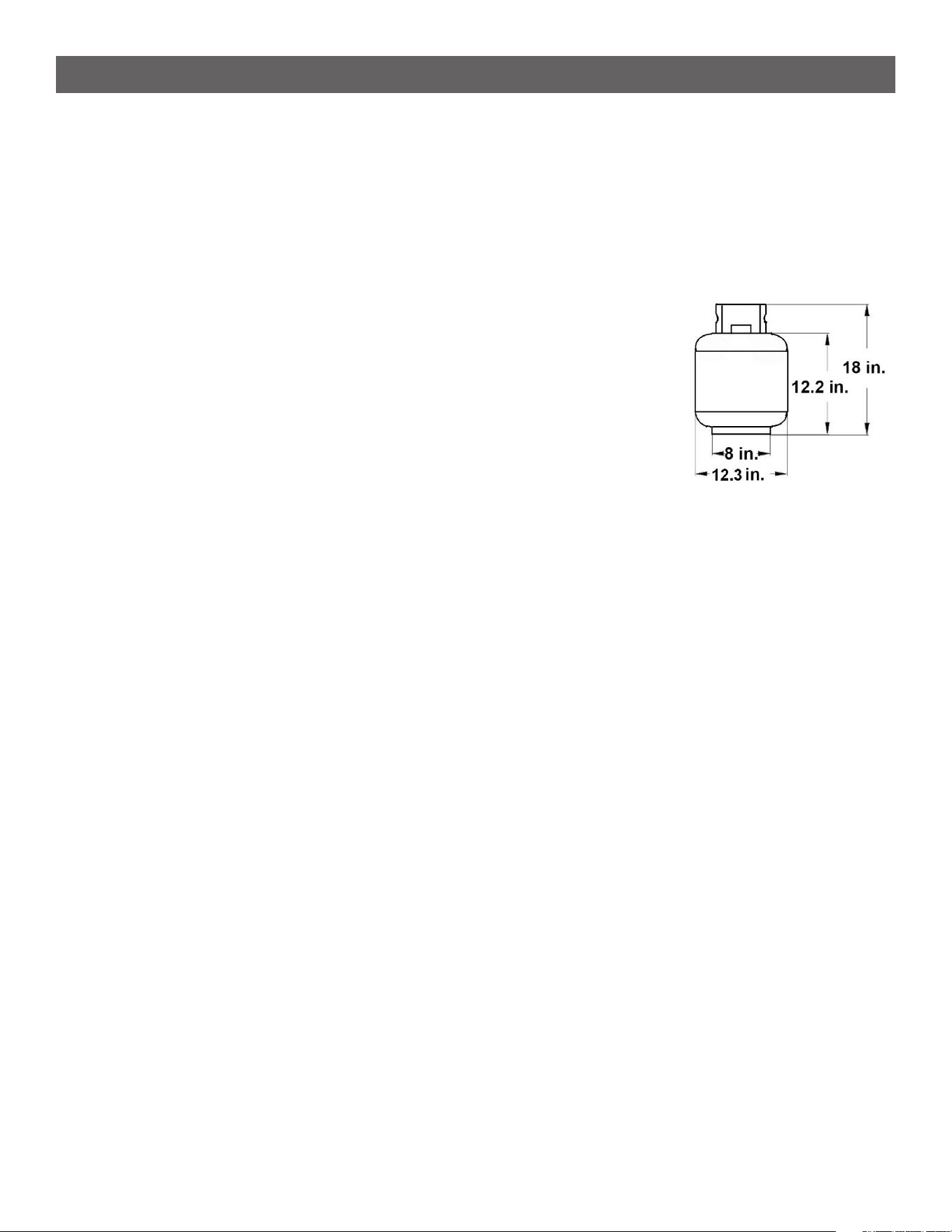
Liquid Propane (LP) Cylinder Requirements
(20-lb Cylinder)
• The approximate specications of an approved LP cylinder is
• 18 inches high, 12.3 inches in diameter and marked for 20 pounds of liquid
propane gas capacity or 47.6 pounds of water capacity.
• Provided with a listed overlling prevention device.
• Provided with a cylinder connection device compatible with the connector for
outdoor cooking appliances
• The Liquid Propane cylinder must be constructed and marked in accordance with the specications for Liq-
uid Propane cylinders by the United States Department of Transportation (DOT) or the National Standard of
Canada, CAN/CSA-B339, Cylinders, Spheres and Tubes for Transportation of Dangerous Goods Commission.
• A dented or rusty liquid propane cylinder may be hazardous and should be checked by your supplier. Never
use a cylinder with a damaged valve.
• The 20-lb cylinder must have a shut off valve terminating in a valve outlet specied, as applicable, for connec-
tion type QCC1 in the standard for compressed gas cylinder valve outlet and inlet connection ANSI/CGA-V-1.
• When appliance is not in use always turn off the gas at the liquid propane cylinder.
• Storage of an outdoor cooking gas appliance indoor is permissible only if the cylinder is disconnected and
removed from the outdoor cooking gas appliance.
• Liquid propane cylinders must be stored outdoors out of the reach of children. They shall not be stored in a
building, garage, or any other enclosed area.
• The cylinder system must be arranged for vapor withdrawal.
• The cylinder must include a collar to protect the cylinder valve.
• Manifold pressure: (operating) 11 inches water column (W.C.), (non-operating) 11.2 inches water column
(W.C.).
• The liquid propane cylinder must be tted with an Overll Protection Device (OPD) and a CGA 791 tank con-
nection.
• Place dust cap on cylinder valve outlet whenever the cylinder is not in use. Only install the type of dust cap on
the cylinder valve outlet that is provided with the cylinder valve. Other types of caps or plugs may result in leak-
age of propane. Remove this cap before use.
• Make sure the gas hose does not contact hot surfaces like the burner shield when the Liquid Propane cylinder
is positioned for use.

5
WHAT’S IN THE BOX
1 Front Left Leg 1pc
2 Back Left Leg 1pc
3 Front Right Leg 1pc
4 Back Right Leg 1pc
5 Lower Brace 2pc
6 Upper Left Brace 1pc
7 Upper Right Brace 1pc
8
Horizontal
Brace
2pc
9 Shelf 1pc
10 Locking Casters 2pc
11 Wheels 2pc
12 Wheel Bushing 2pc
13
Broiler
Grease Pan
1pc
14 Grease Cup Bracket 2pc
15 Grease Cup 2pc
16 Burner Body 1pc
17
Broiler
Door Handle
1pc
18
Broiler
Rack Supports
2pc
PART COMPONENT DESCRIPTION QTY
19 Broiler Rack 1pc
20
Griddle
Grease Chute
1pc
21 Grease Cup Tray 1pc
22 Left Side Table 1pc
23 Right Side Table 1pc
24 Ignitor Bracket 1pc
25 Griddle Plate 1pc
26 Short Lid Hinge 2pc
27 Long Lid Hinge 2pc
28 Griddle Lid 1pc
29
Broiler
Bafe Knobs
2pc
30 Burner Knobs 3pc
31 Garbage Bag Frame 1pc
32 Paper Towel Holder 1pc
33 Propane Tank Bracket 1pc
34 Propane Tank Wire 1pc
PART COMPONENT DESCRIPTION QTY
Phillips Head Screw
1/4-20x1/2”
Phillips Head Screw
5/32-32x25/64”
Shoulder Screw
1/4”
25pc
A
8pc
B
16pc
C
PART HARDWARE DESCRIPTION QTY
Washer
5/32”
6pcD
2pc
F
Wheel Washer
5/16”
G
Wheel Nut
5/16”
2pc
I
H
Nut
1/4”
8pcE
PART HARDWARE DESCRIPTION QTY
AA Battery
1pc
Wrench
1pc
6
ASSEMBLY INSTRUCTIONS
Before beginning assembly, installation or operation of product, make sure all parts are present. Compare parts
with package contents list. If any part is missing or damaged, do not attempt to assemble, install or operate the
product. Contact customer service for replacement parts.
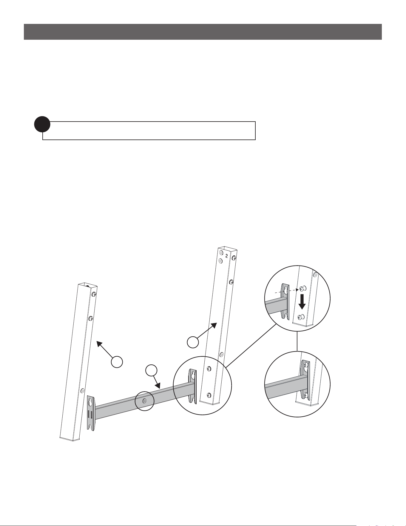
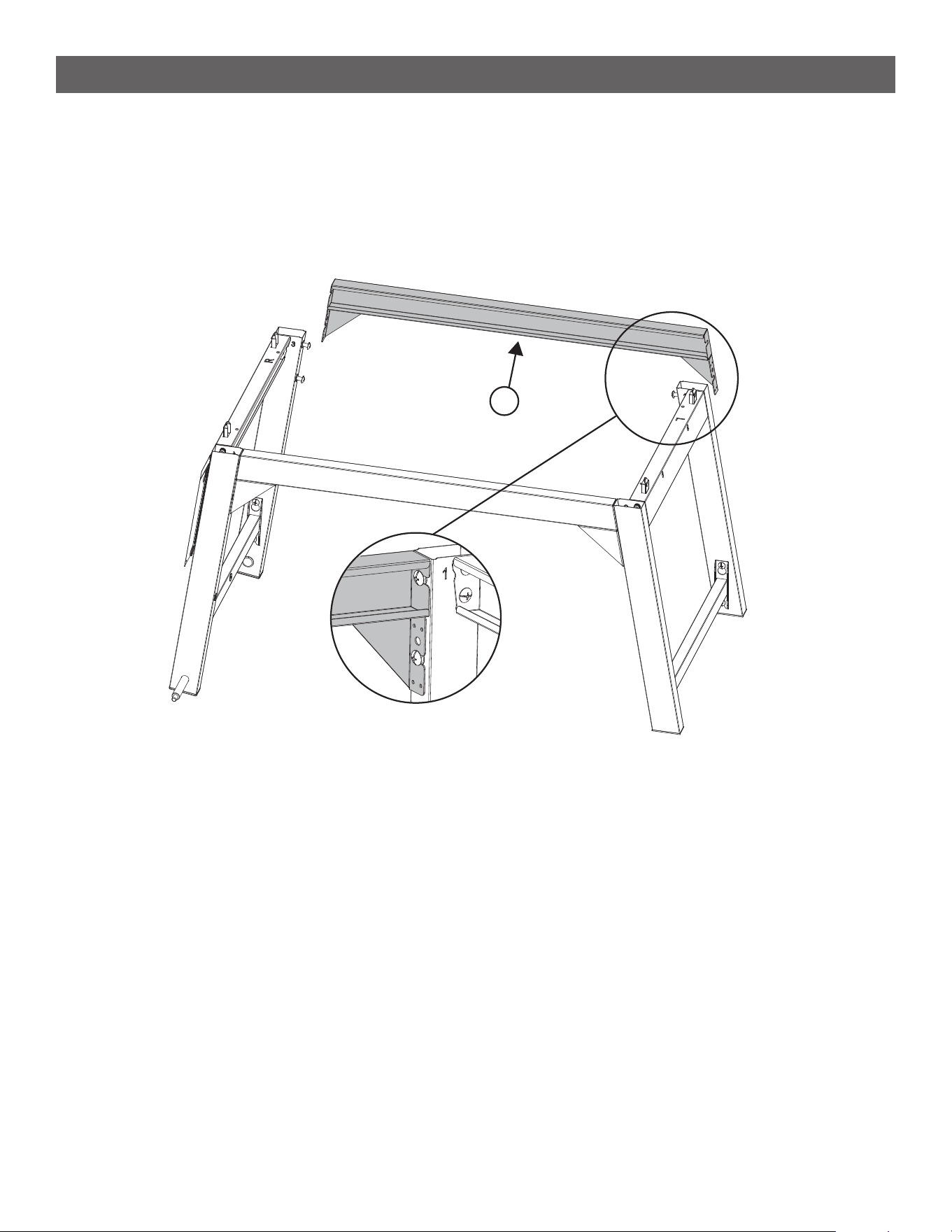
STEP 1
--------------------------------------------------------------------------------------
• Loosen the bottom two screws on Back Left Leg (2) and hook the Lower Brace (5) to it. See [ I ]
• Tighten the screws. See [ II ]
• Attach the Front Left Leg (1) in the same way.
Note: Ensure the threaded hole in the middle of the lower brace is facing the right way. Reference the diagram.
Estimated asembly time:
2 hours
Tools you will need:
• Phillips Head Screwdriver
• Adjustable Wrench
Note: Step 14 requires two people to complete safely.
!
[ I ]
[ II ]
1
5
2
7
ASSEMBLY INSTRUCTIONS
STEP 2
--------------------------------------------------------------------------------------
• Attach the Upper Left Brace (6) to the left leg assembly using 4 A Screws.
A
x 4
6
STEP 3
--------------------------------------------------------------------------------------
• Loosen the bottom two screws on Back Right Leg (4) and hook the Lower Brace (5) to it per the detail
view. Tighten the screws.
• Attach the Front Right Leg (3) in the same way.
Note: Ensure the threaded hole in the middle of the lower brace is facing the right way. Reference
the diagram.
!
[I]
[II]
5
4
3
8
ASSEMBLY INSTRUCTIONS
STEP 4
--------------------------------------------------------------------------------------
• Attach the Upper Right Brace (7) to the right leg assembly using 4 A Screws.
A
x 4
7
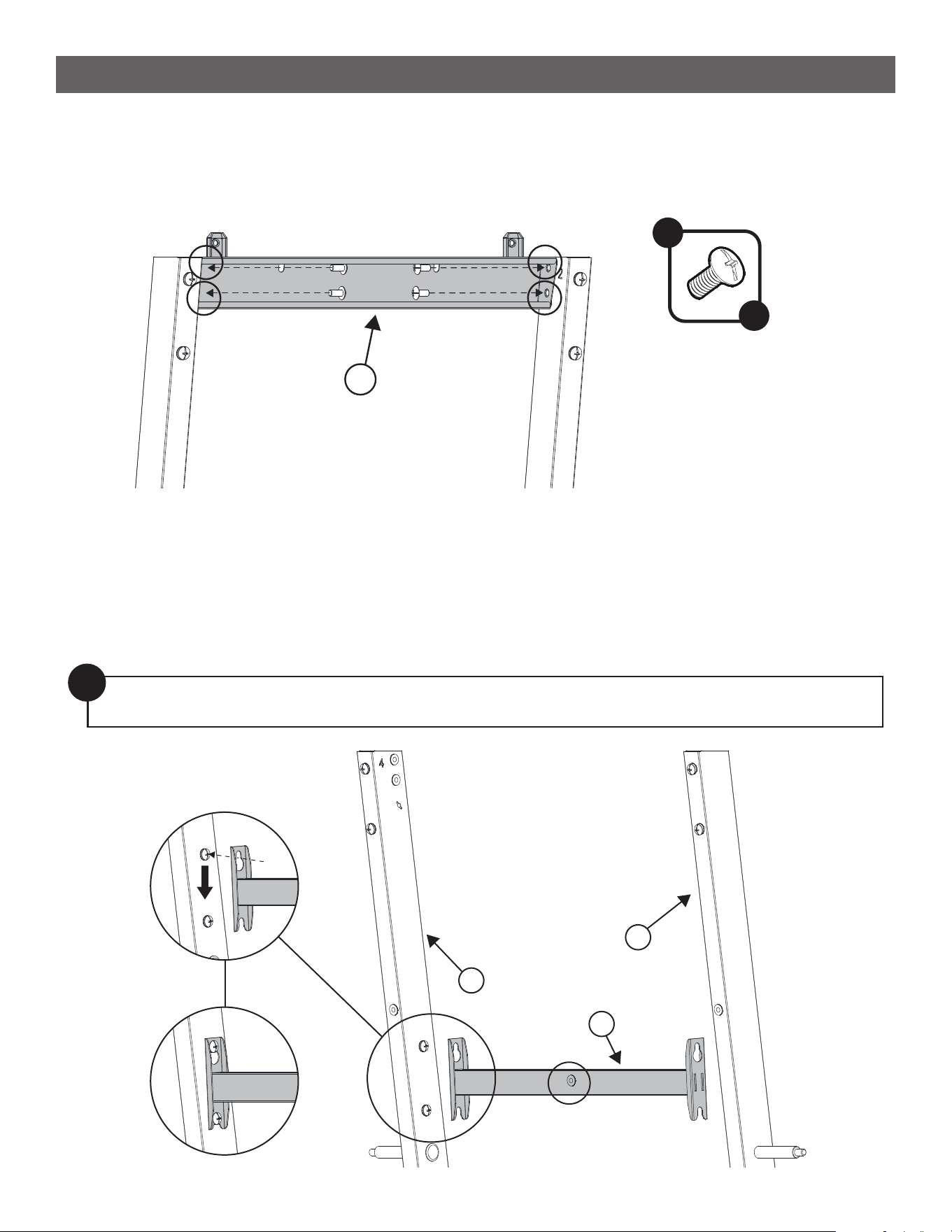
STEP 5
--------------------------------------------------------------------------------------
• Loosen the top two screws on each of the legs.
• Slide the Horizontal Brace (8) under both screw heads of the left leg frame and tighten. Repeat for the right
leg frame.
8
9
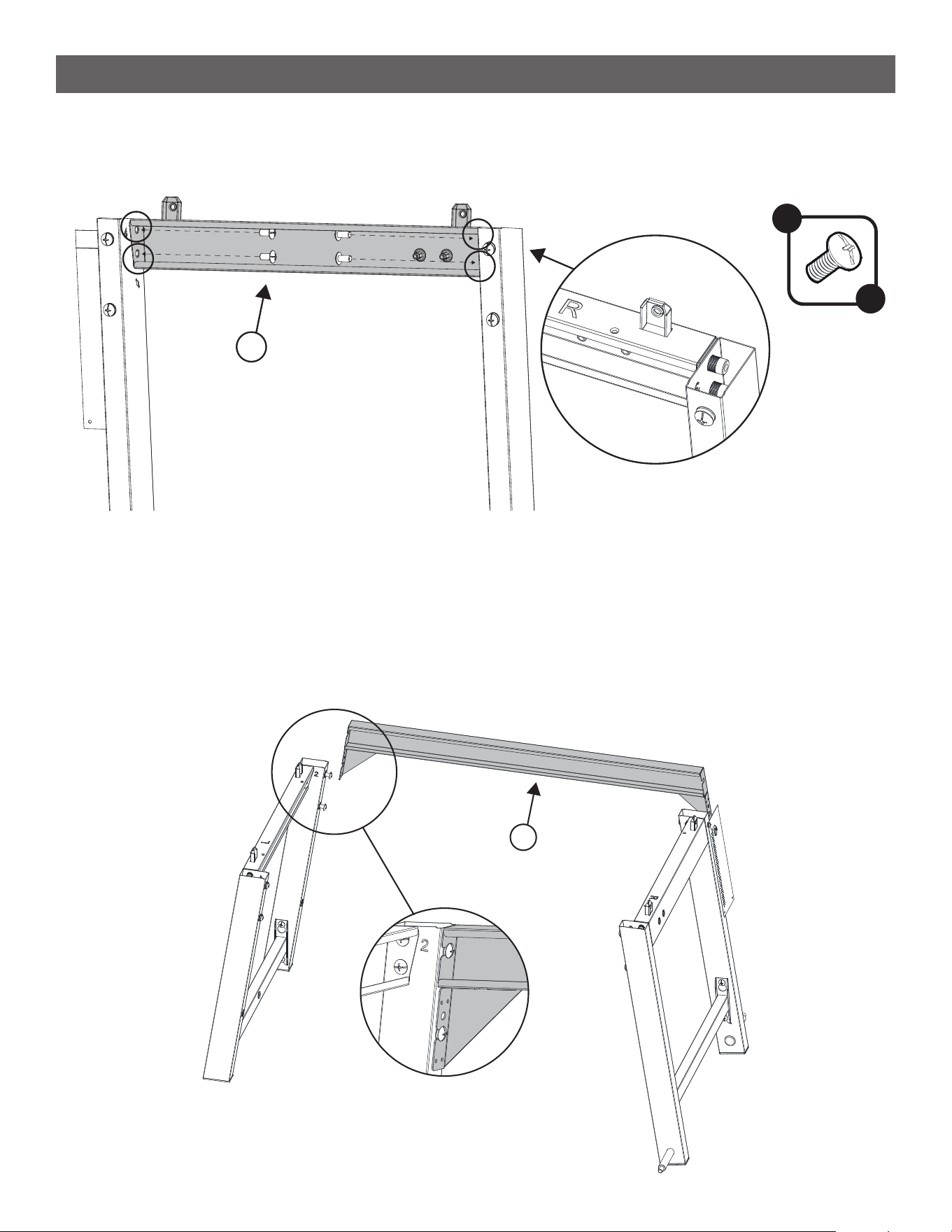
ASSEMBLY INSTRUCTIONS
STEP 6
--------------------------------------------------------------------------------------
• Attach the second Horizontal Brace (8) in the same way.
8
10
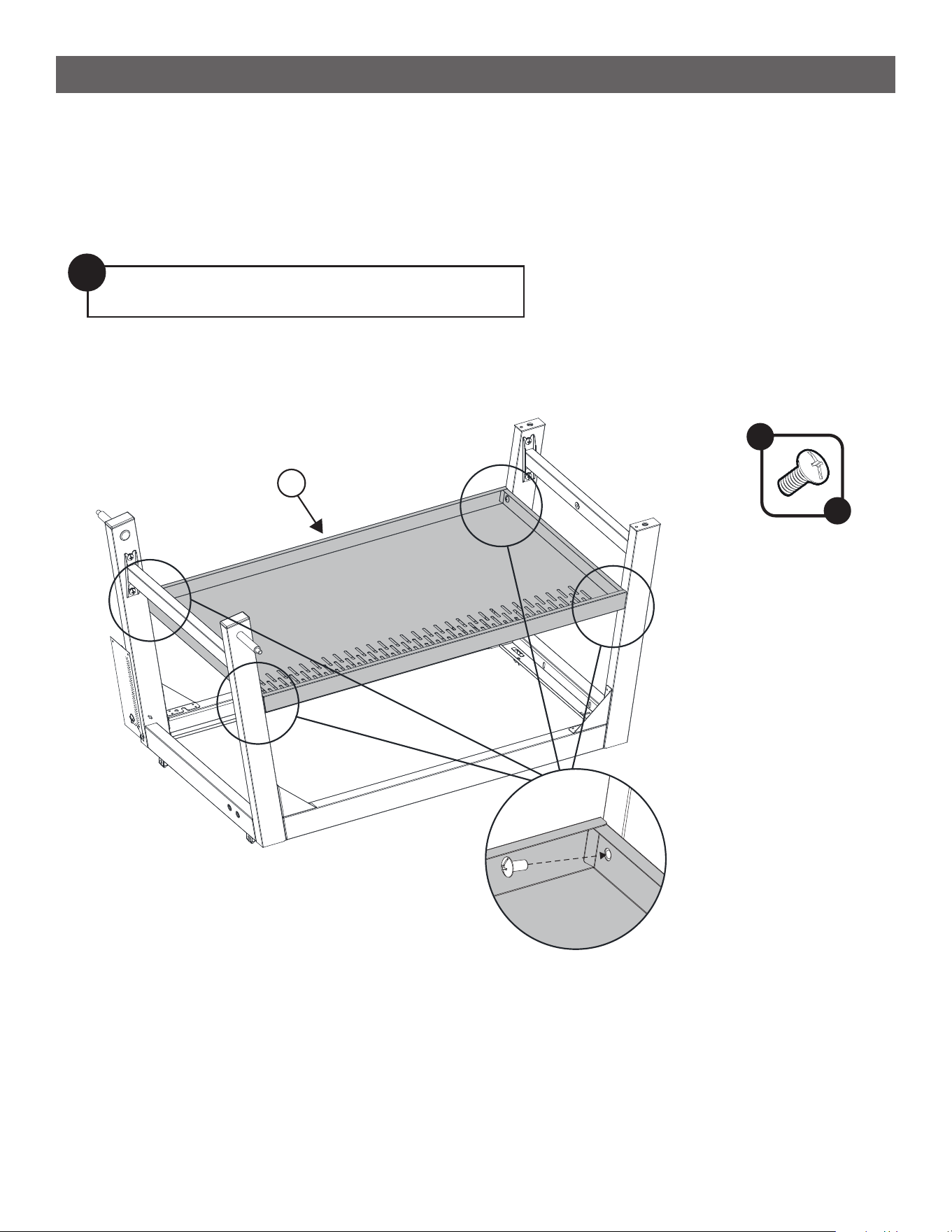
ASSEMBLY INSTRUCTIONS
STEP 7
--------------------------------------------------------------------------------------
• Flip the frame upside down and orient the legs with horizontal pegs to your left.
• Place the Shelf (9) upside down in between the frame so that the hole pattern is closer to you. Adjust the
shelf so that the screw holes in the 4 corners by the legs line up.
• Attach the shelf to the frame using 4 A Screws.
Note: Ensure the holes on the shelf are facing you.
!
A
x 4
9
11
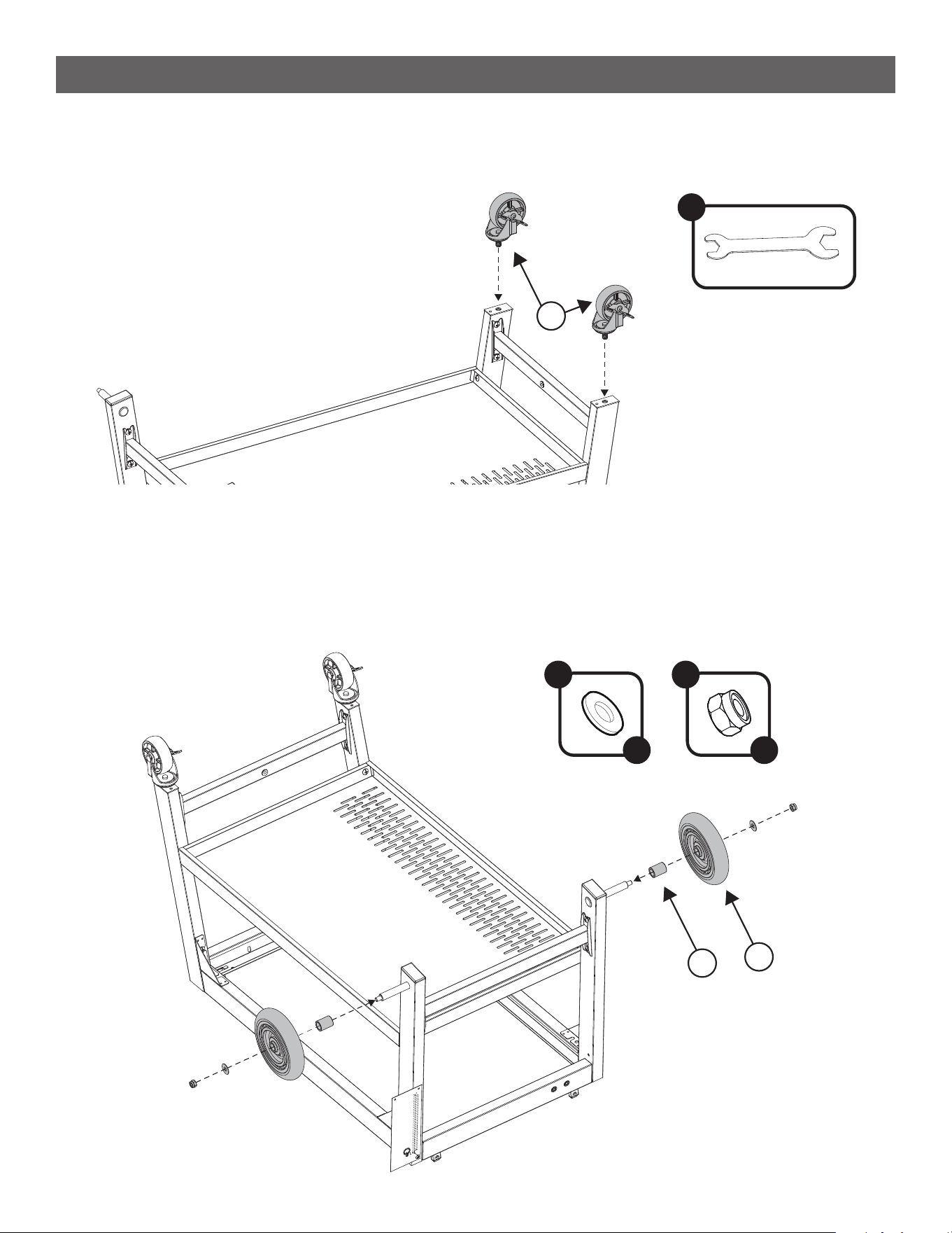
ASSEMBLY INSTRUCTIONS
STEP 8
--------------------------------------------------------------------------------------
• Using the supplied Wrench attach the two Locking Casters (10) to the bottom of the legs on your right.
I
10
F
x 2
G
x 2
12
11
STEP 9
--------------------------------------------------------------------------------------
• In this order, slip the Wheel Bushing (12) over the peg, the Wheel (11), Wheel Washer (F), and secure it all
with the Wheel Nut (G). Repeat for the other wheel.
12
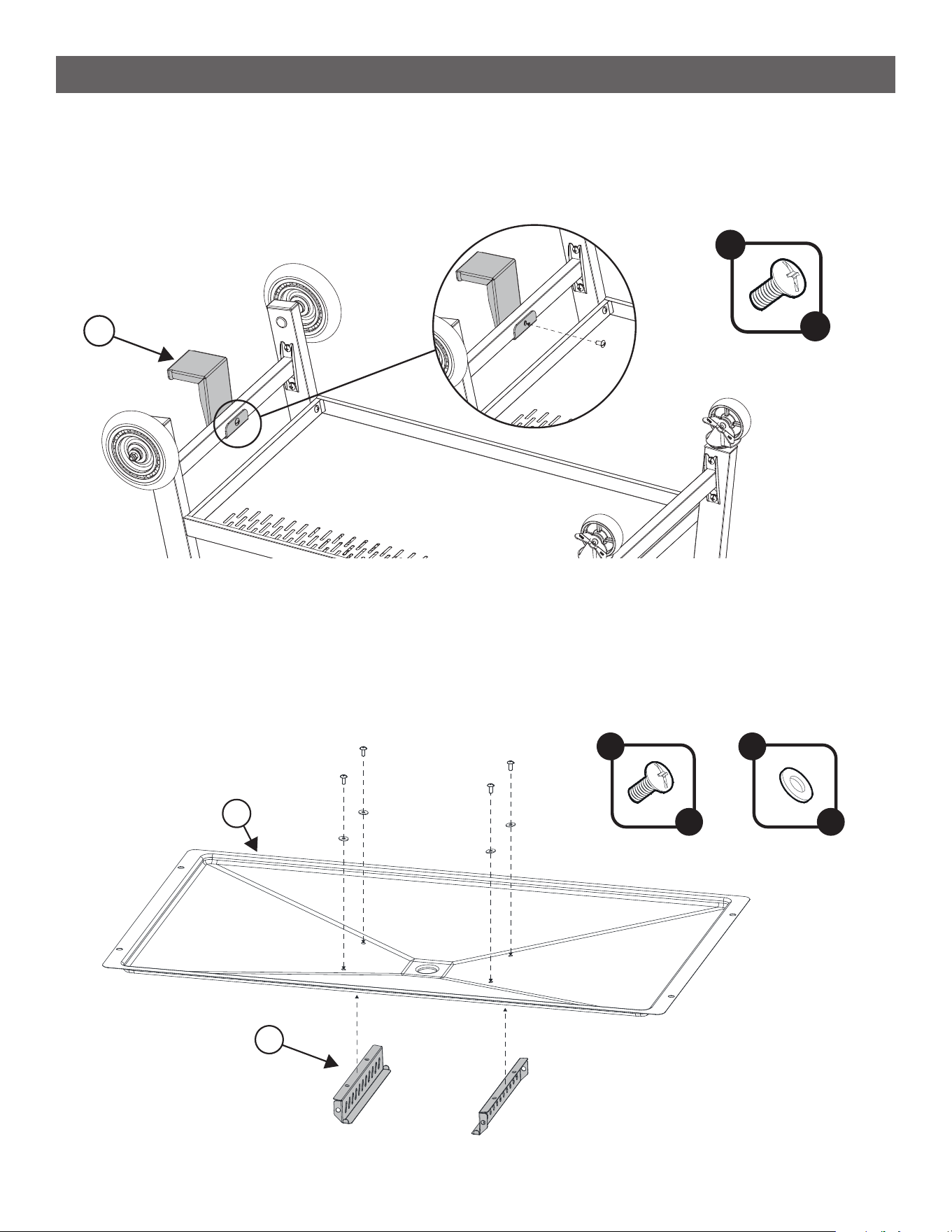
ASSEMBLY INSTRUCTIONS
STEP 10
--------------------------------------------------------------------------------------
• Attach the Propane Tank Bracket (33) to the bottom brace on the wheel side using 1 A Screw.
A
x 1
33
STEP 11
--------------------------------------------------------------------------------------
• Attach two Grease Cup Brackets(14) to the Broiler Grease Pan (13) using 2 C Screws with 2 D Washers
each. Ensure the ledge of each bracket are facing inward towards each other.
C
x 4
D
x 4
13
14
13
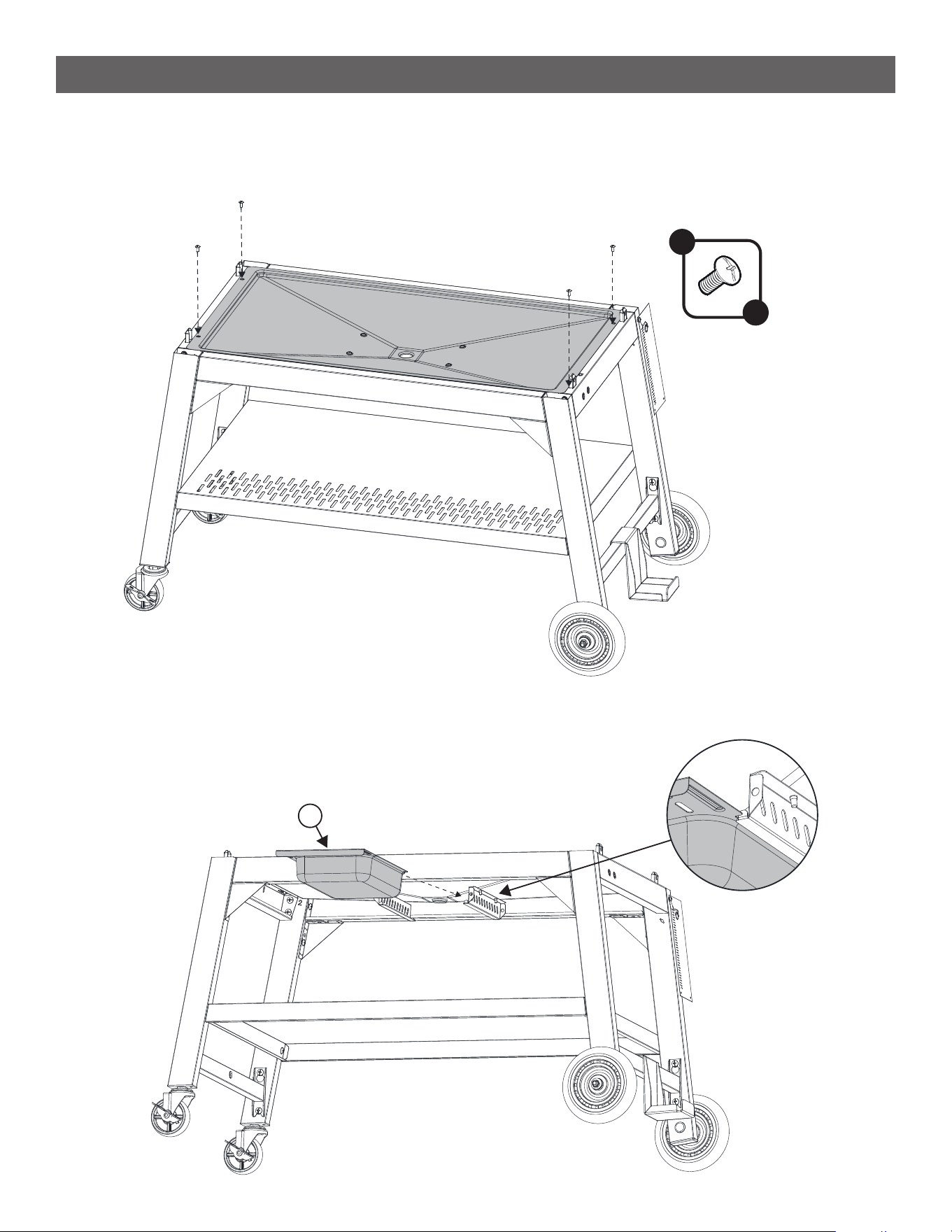
ASSEMBLY INSTRUCTIONS
STEP 12
--------------------------------------------------------------------------------------
• Place the broiler grease pan on top of the assembled frame and secure it with 4 C Screws.
C
x 4
STEP 13
--------------------------------------------------------------------------------------
• Insert the Grease Cup (15) to the bottom of the broiler grease pan.
15
14
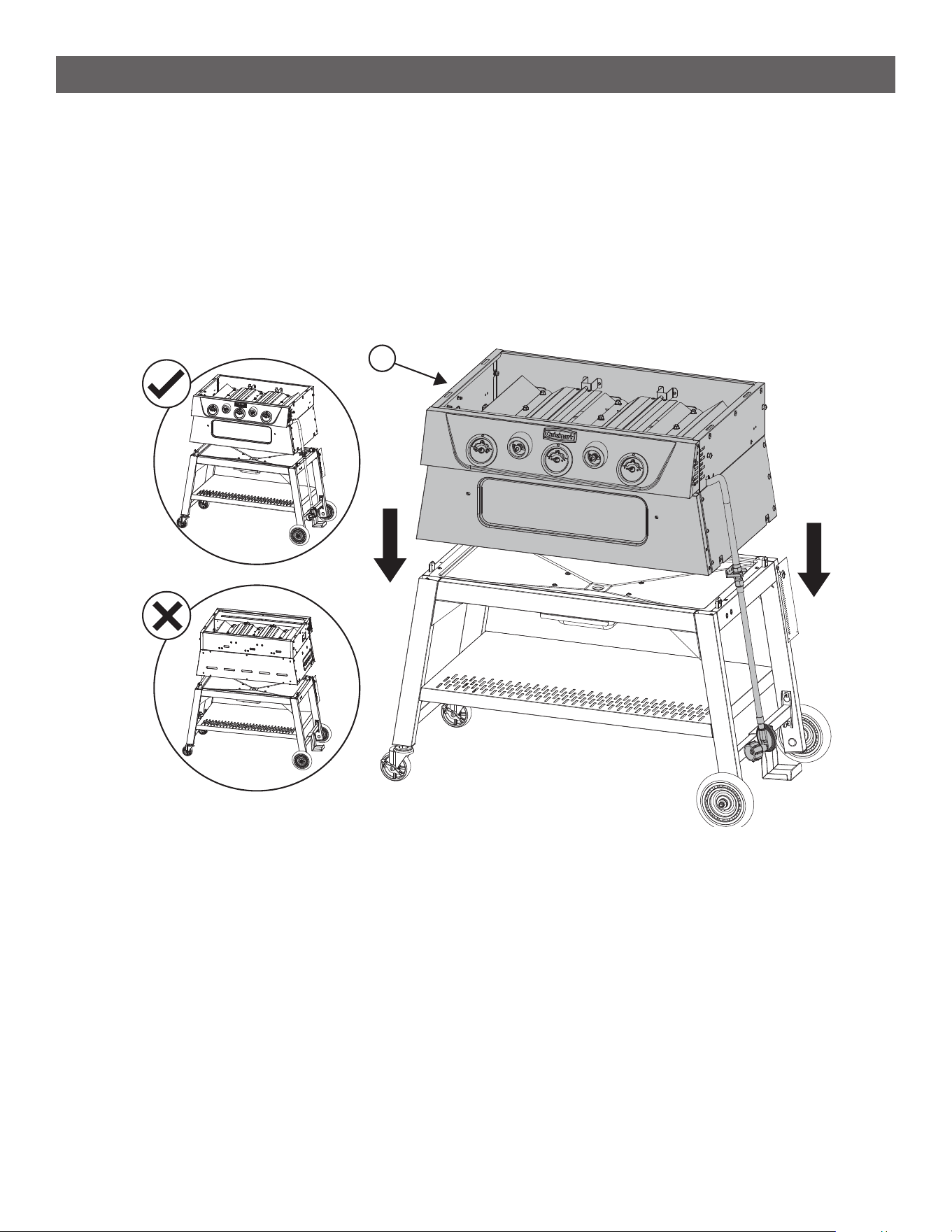
ASSEMBLY INSTRUCTIONS
STEP 14
--------------------------------------------------------------------------------------
• This step should be performed by two people.
• Pick up the Burner Body (16) and place it on top of the cart, ensuring the posts of the cart slot into the
holes of the burner body in the four corners.
• NOTE: Pay attention to the correct orientation of the burner body. From the front, the wheels are on the
right, and the casters are on the left.
16
15
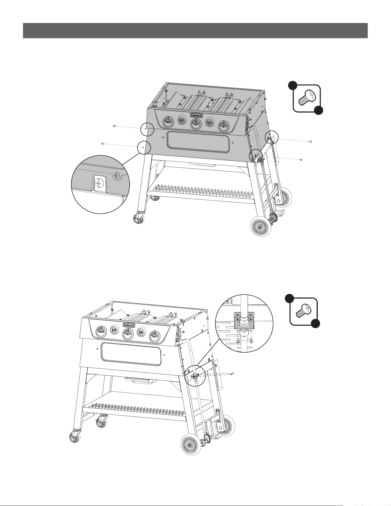
ASSEMBLY INSTRUCTIONS
STEP 15
--------------------------------------------------------------------------------------
• Secure the Burner Body (16) to the frame using 4 A Screws in each corner.
STEP 16
--------------------------------------------------------------------------------------
• Secure the gas hose to the right side of the frame using 2 C Screws.
A
x 4
C
x 2
16
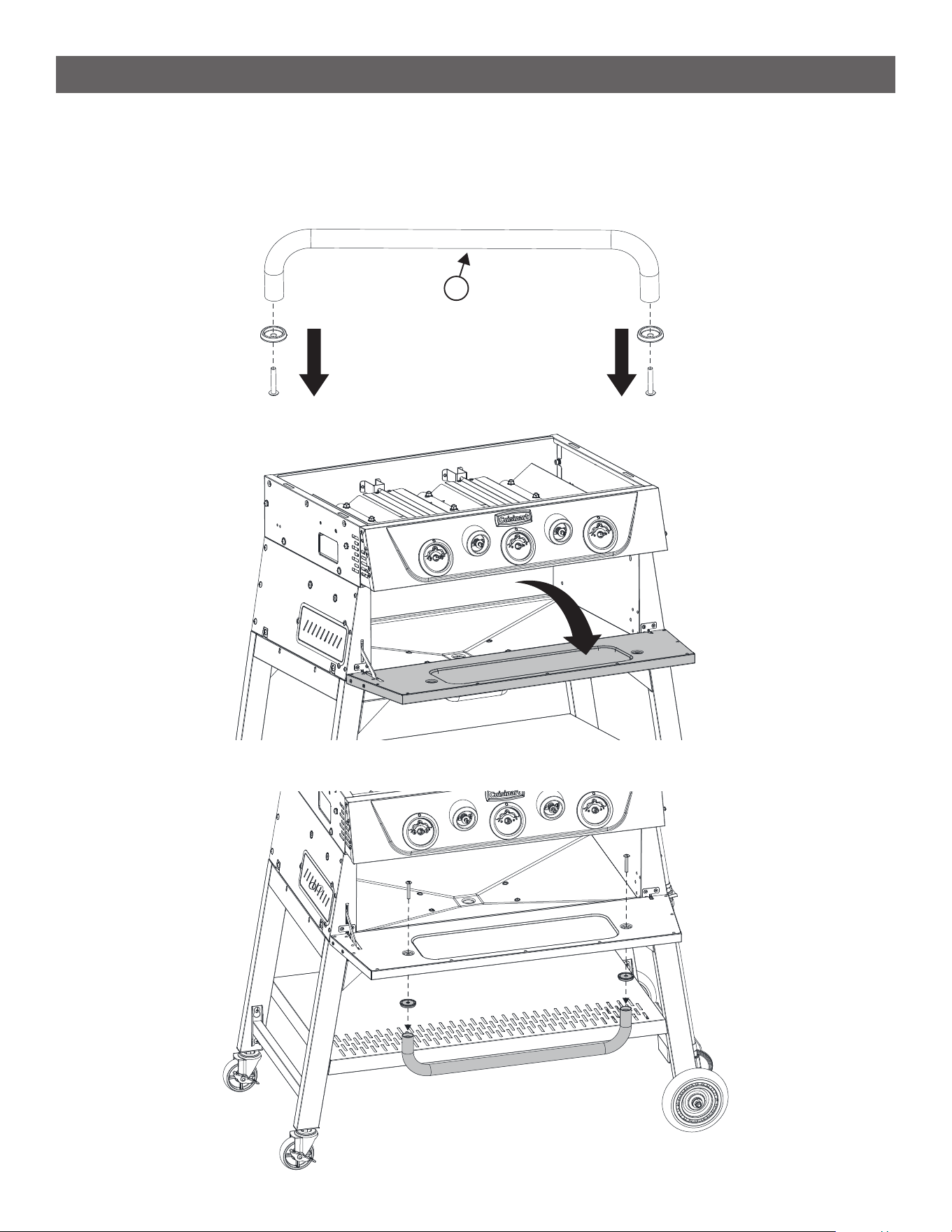
ASSEMBLY INSTRUCTIONS
STEP 17
--------------------------------------------------------------------------------------
• Remove the preassembled screws and bezel from the Broiler Door Handle (17).
• Attach the handle to the broiler door by rst pushing the screws through the door from the inside out, then
put the bezels over the screws, and nally attach the handle.
17
17
ASSEMBLY INSTRUCTIONS
STEP 18
--------------------------------------------------------------------------------------
• Hook the angled side of the Broiler Rack Support (18) to the top two holes of the broiler chamber.
• Let the support pivot down and insert the L shaped end into the holes at the bottom. Repeat for both
sides.
• These supports are intended to be easily removable for cleaning.
[ I ]
[ III ]
18
[ II ]
STEP 19
--------------------------------------------------------------------------------------
• Slip the Broiler Rack (19) in between any of the 3 positions of the support bars.
• There is a downward facing feature on the sides of the rack which should be oriented towards the back.
This feature acts as a stopper to reduce the risk of the rack being pulled out by accident during use.
19
18
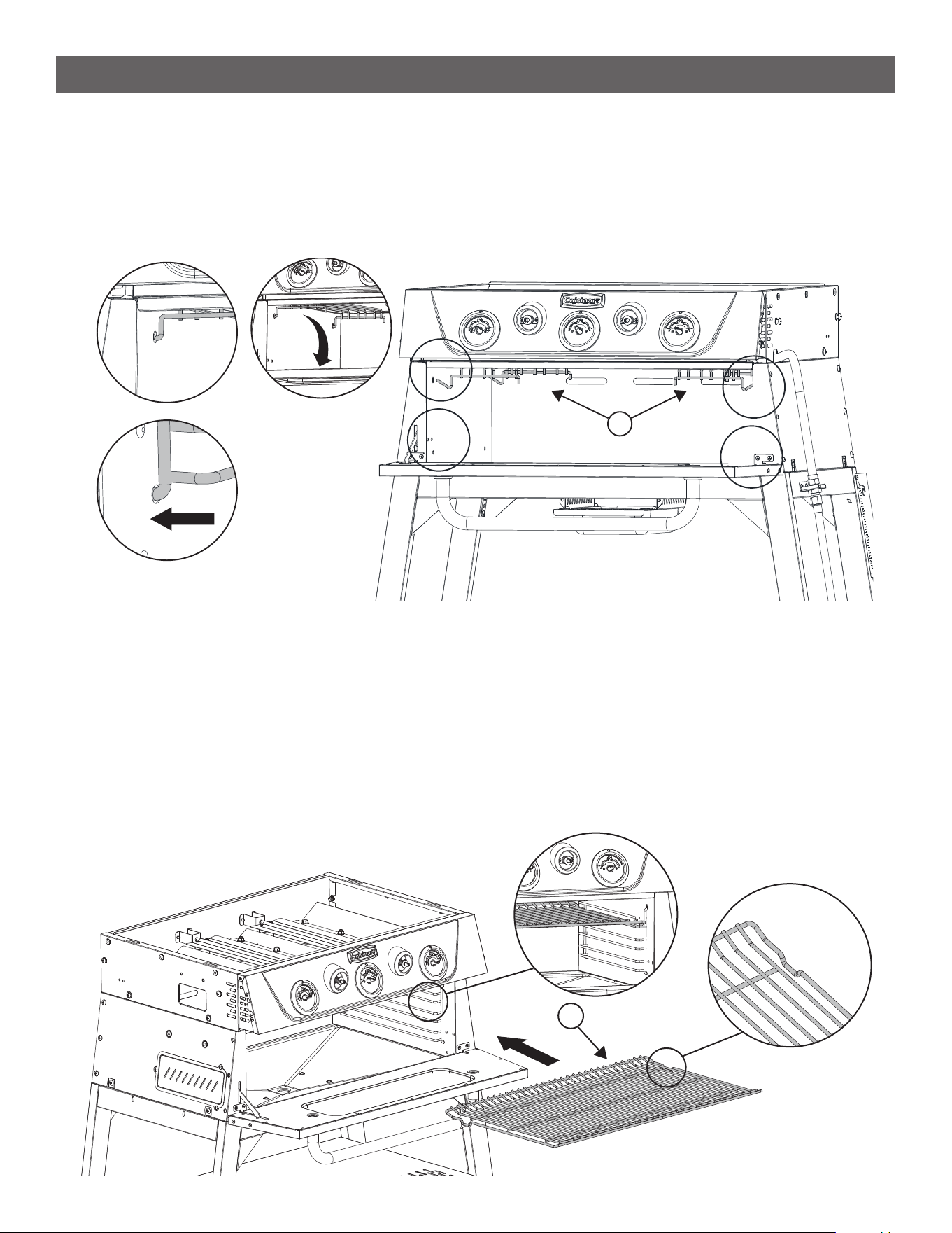
ASSEMBLY INSTRUCTIONS
STEP 20
--------------------------------------------------------------------------------------
• Insert the Griddle Grease Chute (20) into the rectangular hole on the left side of the burner body from the
inside out.
• Secure the chute using 2 C Screws with 2 D Washers.
C
x 2
20
D
x 2
STEP 21
--------------------------------------------------------------------------------------
• Attach the Grease Cup Tray (21) to the left side of the burner body using 2 A screws
A
x 4
21
19
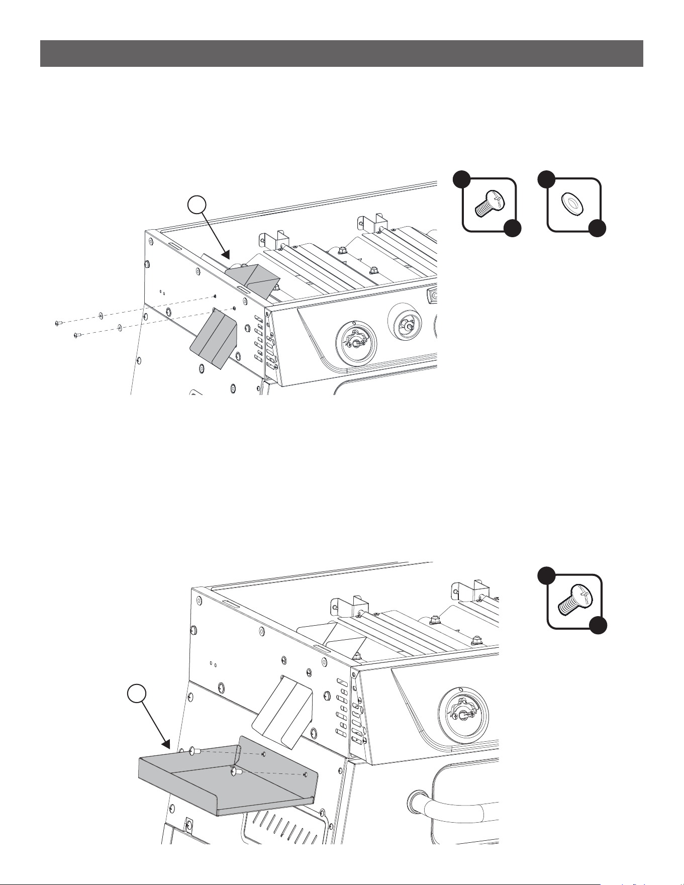
ASSEMBLY INSTRUCTIONS
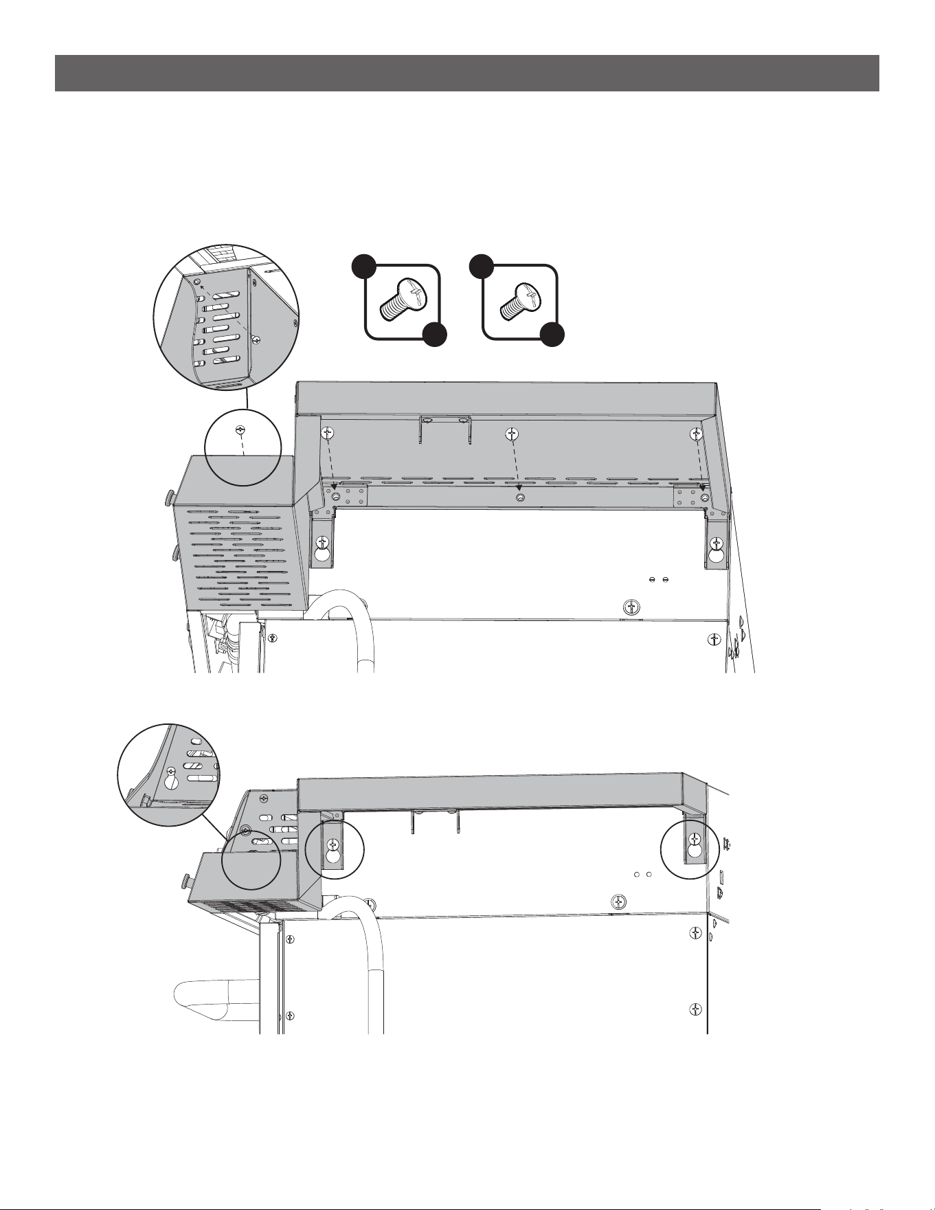
STEP 22
--------------------------------------------------------------------------------------
• Loosen but do not remove two screws that are assembled to the left side of the burner body.
• Remove the top screw from the side of the control panel, and loosen but do not remove the bottom screw.
STEP 23
--------------------------------------------------------------------------------------
• Hook the Left Side Table (22) onto the burner body by the 3 loosened screws from the previous step.
• Ensuring the table is well aligned with the burner body, tighten all 3 screws.
22
20
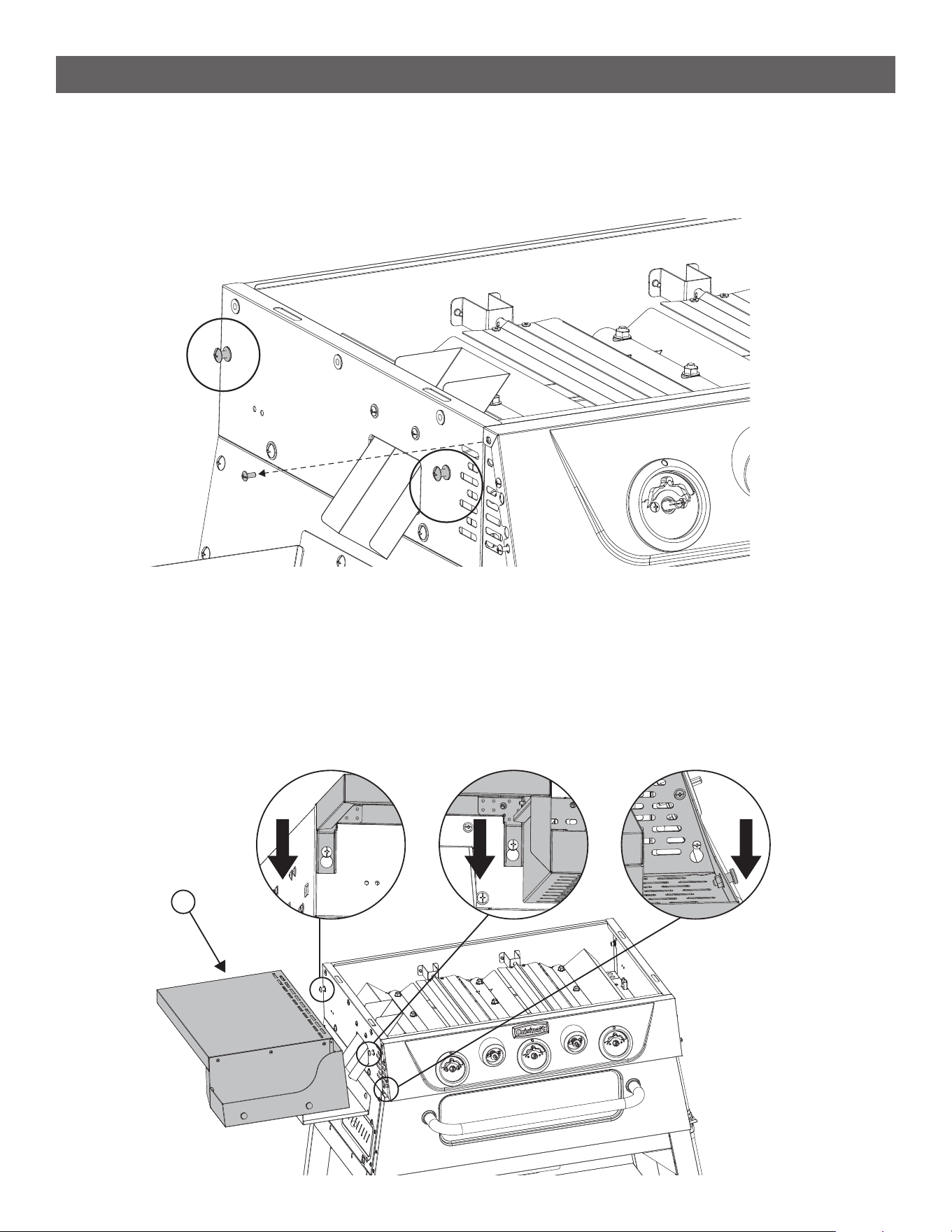
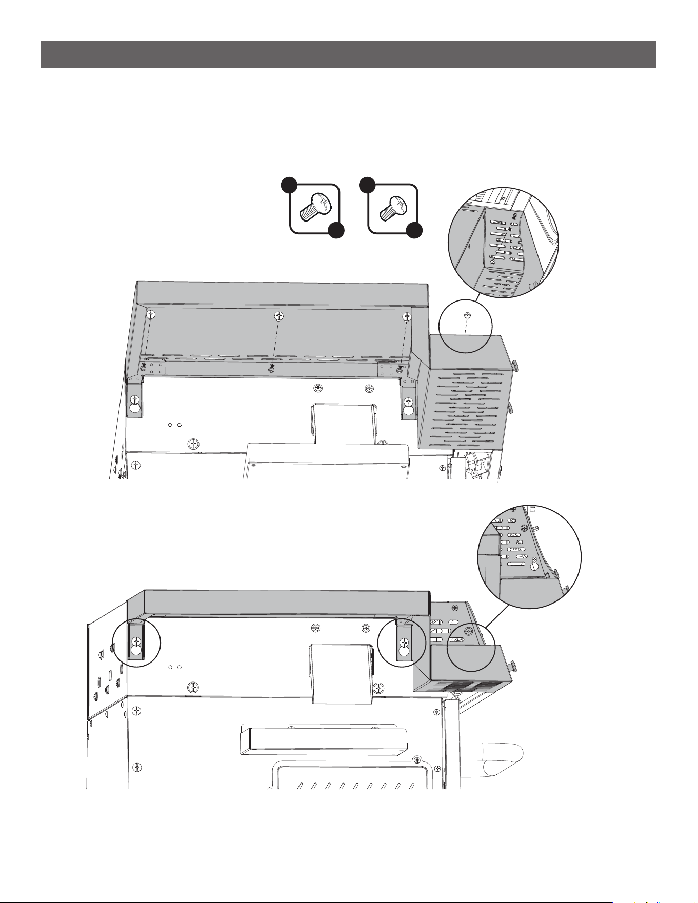
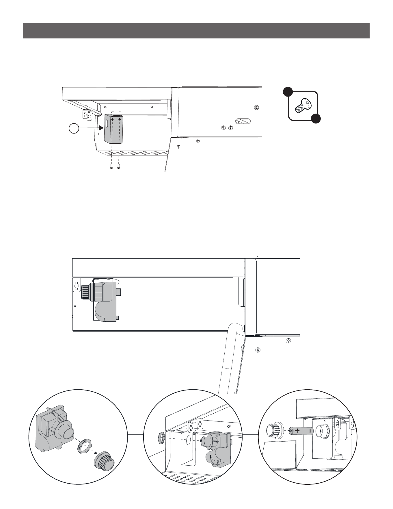
ASSEMBLY INSTRUCTIONS
STEP 24
--------------------------------------------------------------------------------------
• Reinstall the C Screw that was removed from the top of the control panel in Step 22.
• From the bottom, install 3 A Screws across the top edge.
A
x 3
C
x 1
21
ASSEMBLY INSTRUCTIONS
STEP 25
--------------------------------------------------------------------------------------
• Repeat steps 22 through 24 to assemble the Right Side Table (23).
A
x 3
C
x 1
22
ASSEMBLY INSTRUCTIONS
STEP 26
--------------------------------------------------------------------------------------
• Attach the Ignitor Bracket (24) to the bottom of the right side table so that the panel with the hole is facing
outward.
24
C
x 2
STEP 27
--------------------------------------------------------------------------------------
• The ignitor should be attached by wires to the right side of the burner body.
• Unscrew the battery cap and plastic nut from the threaded portion of it. See [ I ]
• Insert the threaded portion into the hole of the ignitor bracket, and secure it using the plastic nut. See [ II ]
• Insert the AA battery (H) into the ignitor with the + side facing out. Screw the battery cap back to secure
the battery. [ III ]
• Test the connection by pressing in on any of the knobs, you should hear a clicking sound.
[ I ] [ II ]
[ III ]
23
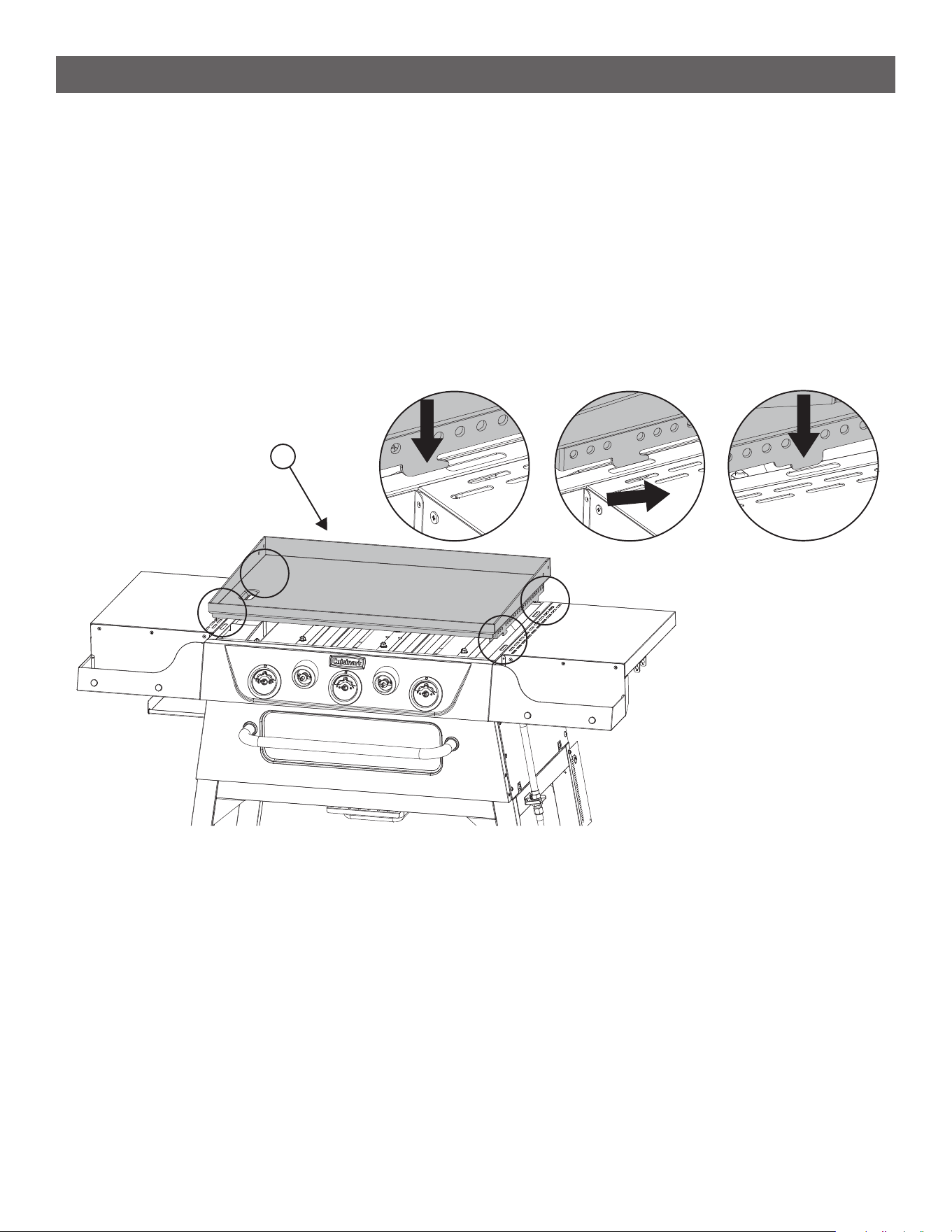
ASSEMBLY INSTRUCTIONS
STEP 28
--------------------------------------------------------------------------------------
• Place the Griddle Plate (25) on top of the burner body and slot the front two hooks into their corresponding
slots. See [ I ]
• Slide the griddle plate towards the back to hook it in place. See [ II ]
• The back of the griddle plate has a tab which will fall into the slot, securing the griddle in place. See [ III ]
• To remove the griddle plate, lift the rear tabs up out of the slot and slide the griddle plate forward to
disengage the front hooks.
25
[ I ] [ II ]
[ III ]
24
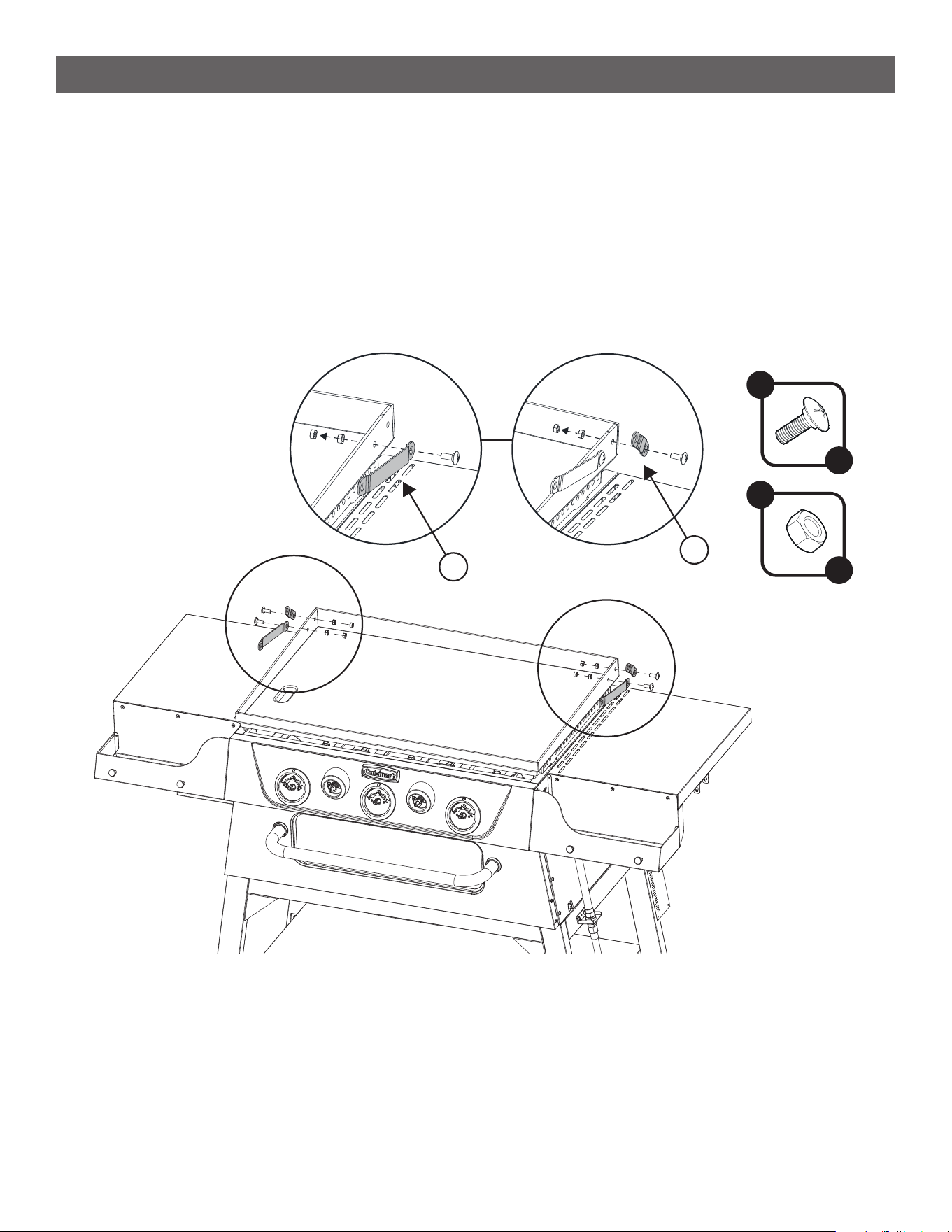
ASSEMBLY INSTRUCTIONS
STEP 29
--------------------------------------------------------------------------------------
• Install the lid hinges to the back corners of the griddle plate. Use a B Screw and 2 E Nuts for each hinge.
Hand tighten the rst nut, then back it off ½ turn. Then holding the rst nut in place fully tighten the second
nut with a wrench to lock them in place. The hinge should be able to turn freely but the nuts should be
tight.
• Assemble the Long Lid Hinge (27) to the front hole. See [ I ]
• Assemble the Short Lid Hinge (26) to the back hole. [ II ]
[I] [II]
B
x 4
E
x 8
27
26
25
ASSEMBLY INSTRUCTIONS
STEP 30
--------------------------------------------------------------------------------------
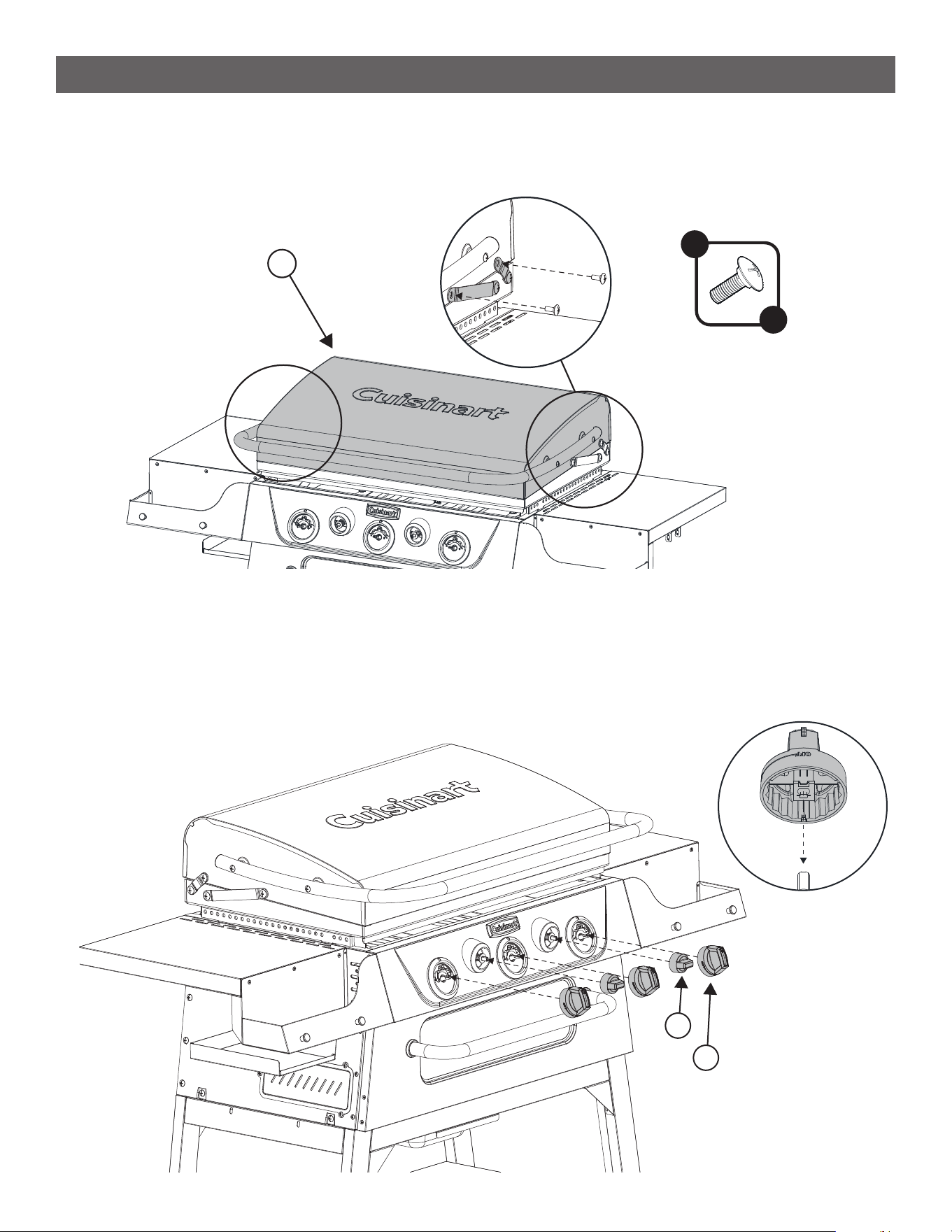
• Place the Lid (28) on top of the griddle plate.
• Attach it to each lid hinge using one B Screw for each hinge.
28
B
x 4
STEP 31
--------------------------------------------------------------------------------------
• Press the 3 Burner Knobs (30) onto the large bezels on the front of the control panel. Note the ‘D-shaped’
stems correspond to ‘D-shaped’ holes in the knob. The red indicator tab should be pointing up.
• Press the Broiler Bafe Knobs (29) onto the smaller bezels that are located between the larger bezels.
29
30
26
ASSEMBLY INSTRUCTIONS
STEP 32
--------------------------------------------------------------------------------------
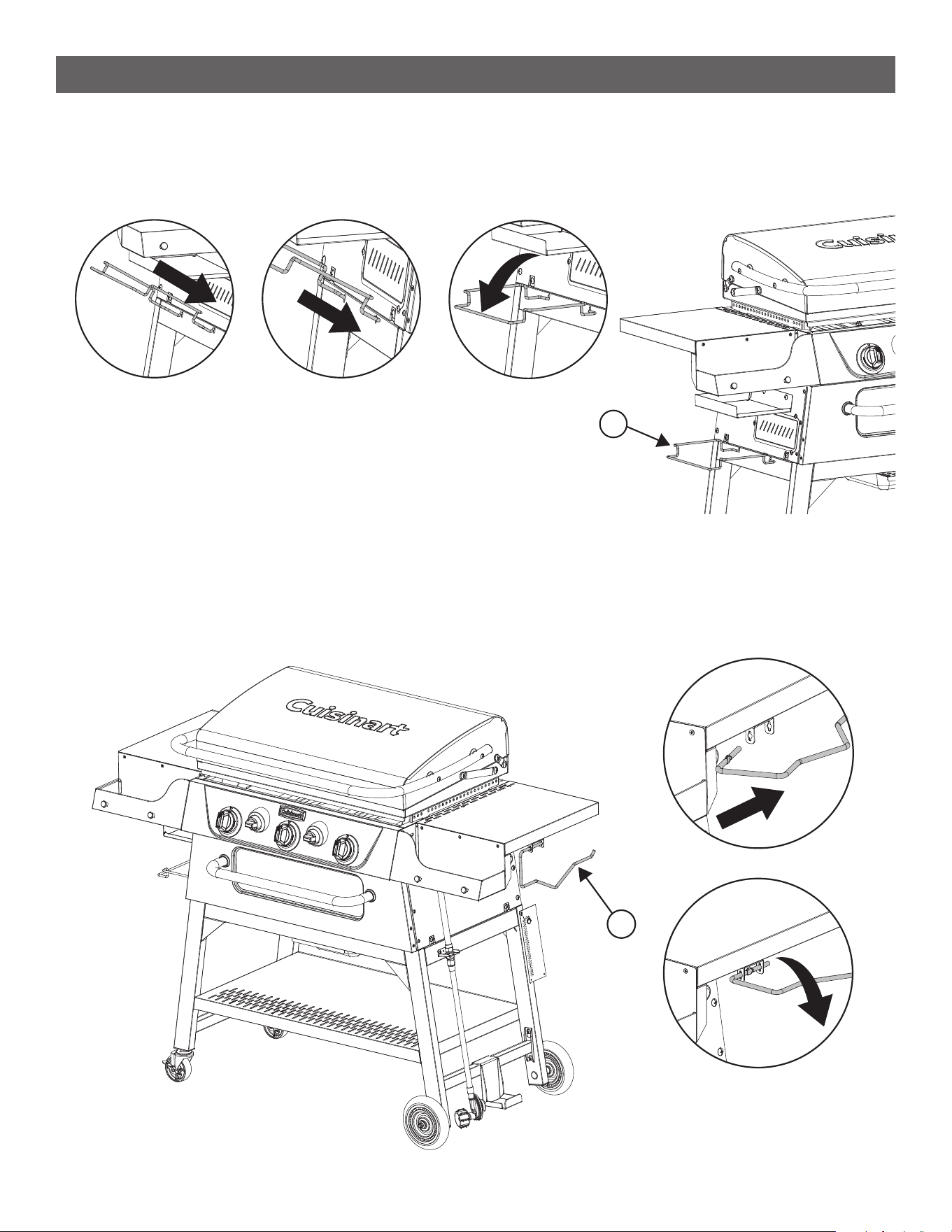
• Hook the Garbage Bag Frame (32) into the left side of the Griddle, below the grease tray.
31
[ I ] [ II ] [ III ]
STEP 33
--------------------------------------------------------------------------------------
• Insert the Paper Towel Holder (32) into the bracket of the right side table.
32
[ I ]
[ II ]
27
ASSEMBLY INSTRUCTIONS
STEP 34
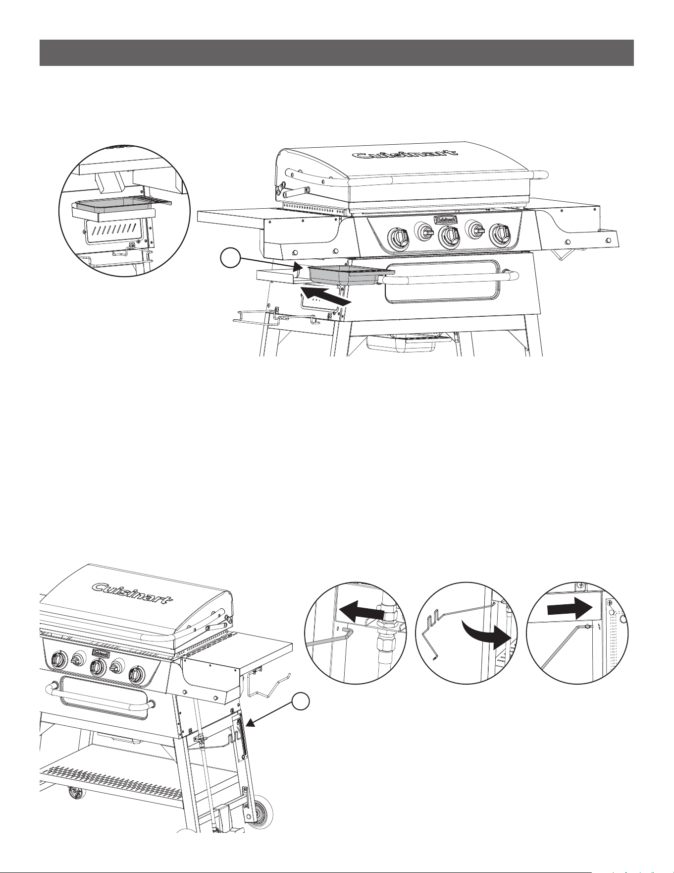
--------------------------------------------------------------------------------------
• Place the Grease Cup (15) into the grease cup tray under the left side table.
15
STEP 35
--------------------------------------------------------------------------------------
• Install the Propane Tank Wire (34) into the right legs. See [ I ]
• Take the hook side of the wire and insert it into the hole of the front right leg. See [ II ]
• Insert the other side of the wire into the key slot of the back right leg and let it drop down locking it in place.
See [ III ]
• The rectangular feature of the wire should be pointing upwards.
34
[ I ] [ II ] [ III ]
28
SETUP INSTRUCTIONS
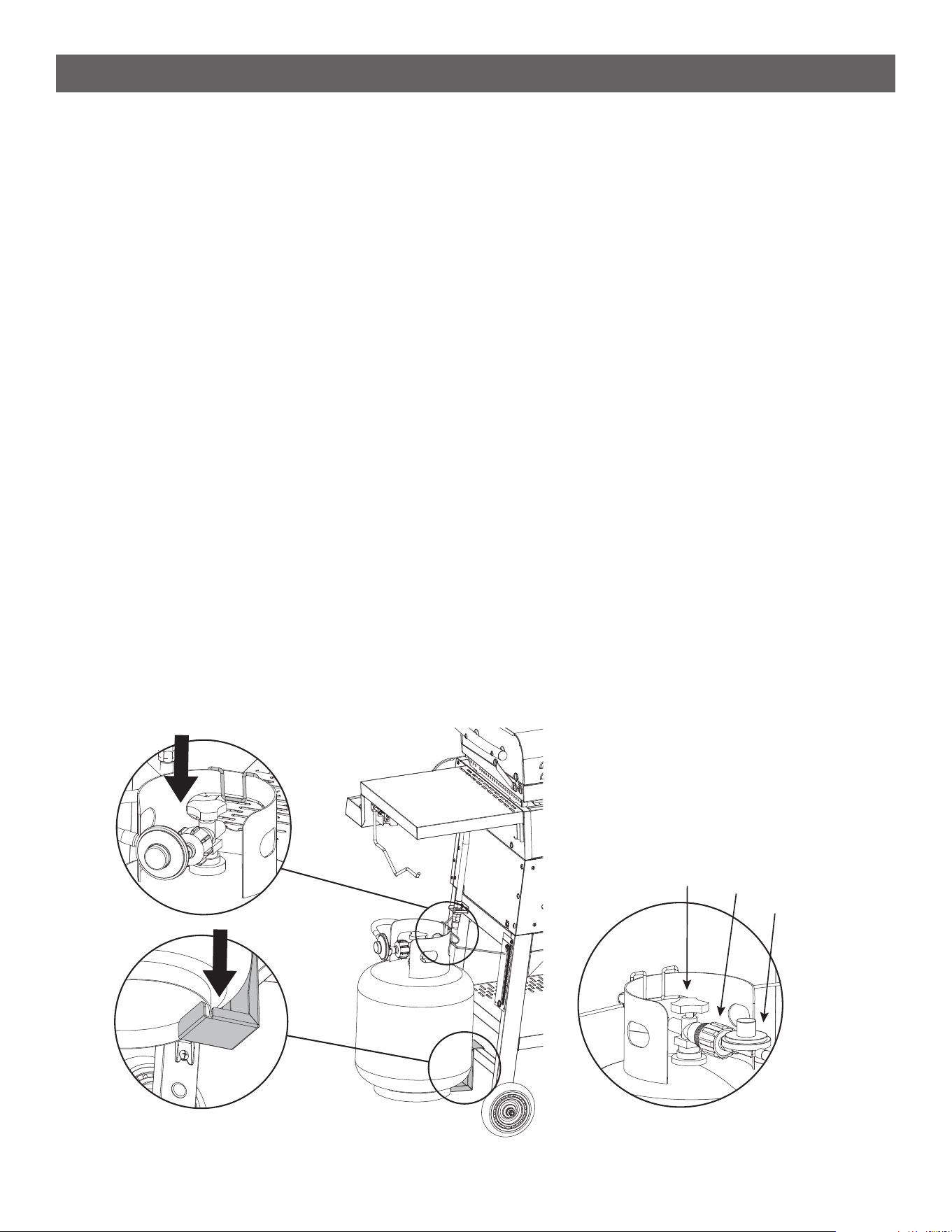
CONNECTING THE LIQUID PROPANE (LP) CYLINDER
--------------------------------------------------------------------------------------
• Double check the cylinder valve to ensure it is in the “OFF” position. If not, turn the valve clockwise until it
stops.
• Conrm the cylinder valve matches the mating style of the regulator.
• Make sure the burner valves are in the “OFF” position. If not, push the knob in and turn it clockwise until
the words “OFF” is displayed on the top of the knob.
• Inspect the regulator assembly to ensure there is no debris or damage.
• Thoroughly inspect the gas hose for any debris or damage like cracks, abrasion, or cuts before each use.
Clean the hose if it is dirty. Do not use the product if the hose is damaged, contact Cuisinart customer
service to get a replacement.
• Place the liquid propane cylinder on the Propane Tank Bracket so that the ring at the bottom of the cylinder
sits inside the notches.
• Flip the tank retention clip down so that it clips onto the upper collar of the LP cylinder. The Cylinder should
be secured in a perfectly upright position.
• Thread the plastic nut of the regulator onto the valve of the LP cylinder by hand. Do not use tools because
they can damage the components resulting in a dangerous gas leak.
• Before lighting the Griddle conduct a leak test, detailed in a later section.
DISCONNECTING THE LIQUID PROPANE (LP) CYLINDER
--------------------------------------------------------------------------------------
• Press in and then turn the burner valve clockwise to “OFF”, then wait until all surfaces are cool.
• Close the LP cylinder valve by turning it clockwise until it stops.
• Detach the LP cylinder from the regulator by turning the regulator nut counter clockwise until it comes off.
• Place dust cap on cylinder valve outlet whenever the cylinder is not in use. Only install the type of dust cap
on the cylinder valve outlet that is provided with the cylinder valve. Other types of caps or plugs may result
in leakage of propane.
[ I ]
[ II ]
Cylinder
Valve
Nut
Regulator
29
Example of a good
rubber seal.
Example of a damaged
rubber seal.
SETUP INSTRUCTIONS
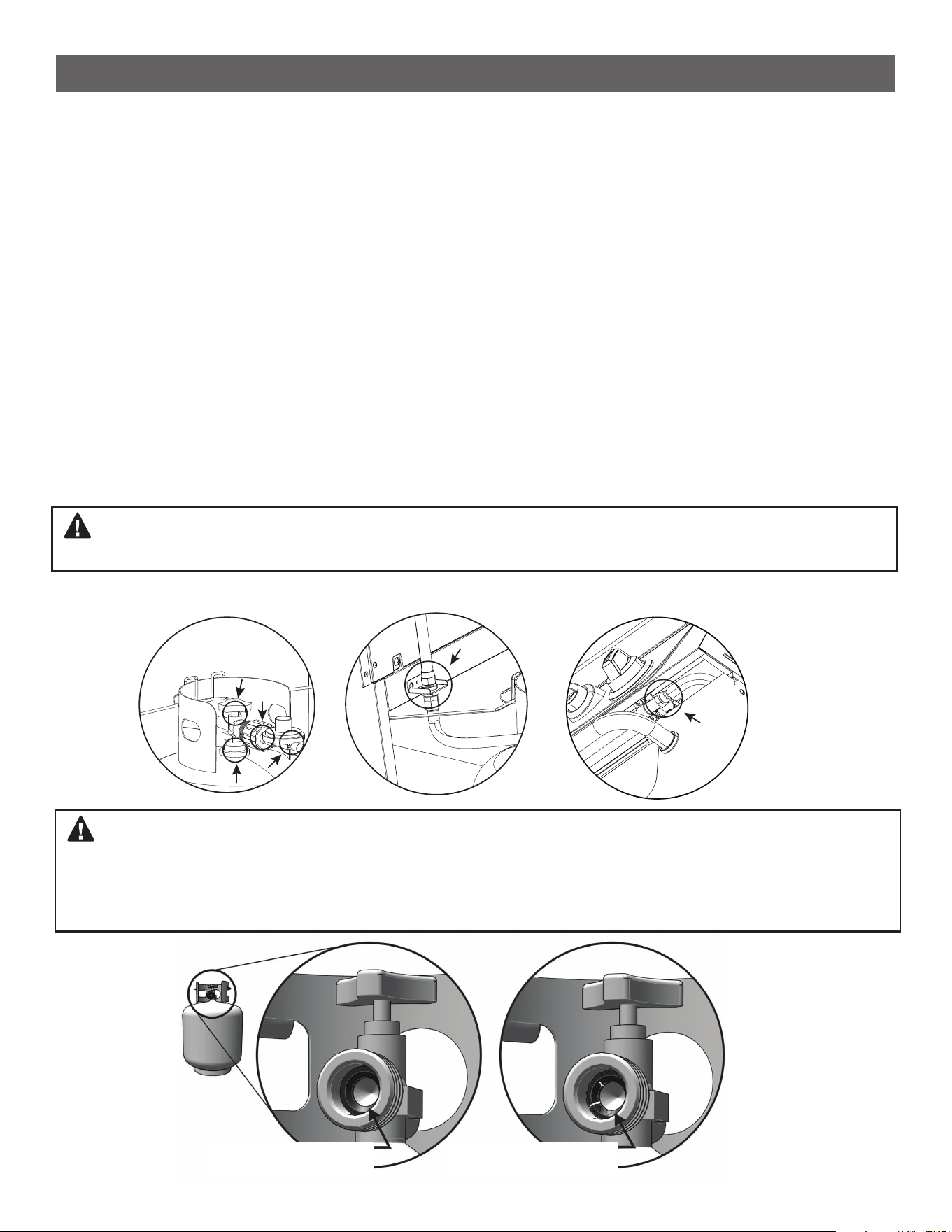
LEAK TEST PROCEDURE
--------------------------------------------------------------------------------------
Although gas connections on the griddle are leak tested prior to shipment, we recommend conducting a leak test
after initial setup and every time an LP cylinder is attached. In addition, we recommend performing a leak test
once a year. If the unexpected smell of gas is detected at any time a full leak test should be performed.
1. Create a solution of 80% water and 20% liquid soap in a spray bottle.
2. Connect the LP cylinder to the product by following the steps in the earlier section “CONNECTING THE LP
CYLINDER”.
3. Turn the LP cylinder valve counterclockwise to open the valve.
4. Spray soapy water to all gas tting connection points focusing on areas where the regulator connects to the
propane tank, where the rubber gas line connects to the corrugated gas line, and where the corrugated line
connects to the valve manifold.
5. If a leak is discovered immediately turn the gas supply off and tighten any loose ttings.
6. Turn the gas back on and recheck.
7. If the leak continues turn off all gas and disconnect the LP cylinder. Contact our customer service team for
further assistance at 866-994-6390 or email [email protected].
WARNING: Check all gas supply ttings for leaks regularly. Do not use the Griddle until all connections have
been checked and do not leak. Do not smoke while leak testing. Never leak test with an open ame.
WARNING: The rubber seal on your propane tank valve may, over time, show marked and visible damage
or deterioration. If the seal has deteriorated a leak may occur even if the connection is tightened fully. Visual
inspection of the seal must be conducted every time a LP gas cylinder is attached to the griddle. If your LP-gas
cylinder shows signs of seal damage, including visible cracks, and pitting, you must return it to the propane tank
supplier.
LP Cylinder
Rubber Gas Line Connection
To Corrugated Line
Corrugated Line Connection
To Manifold
30
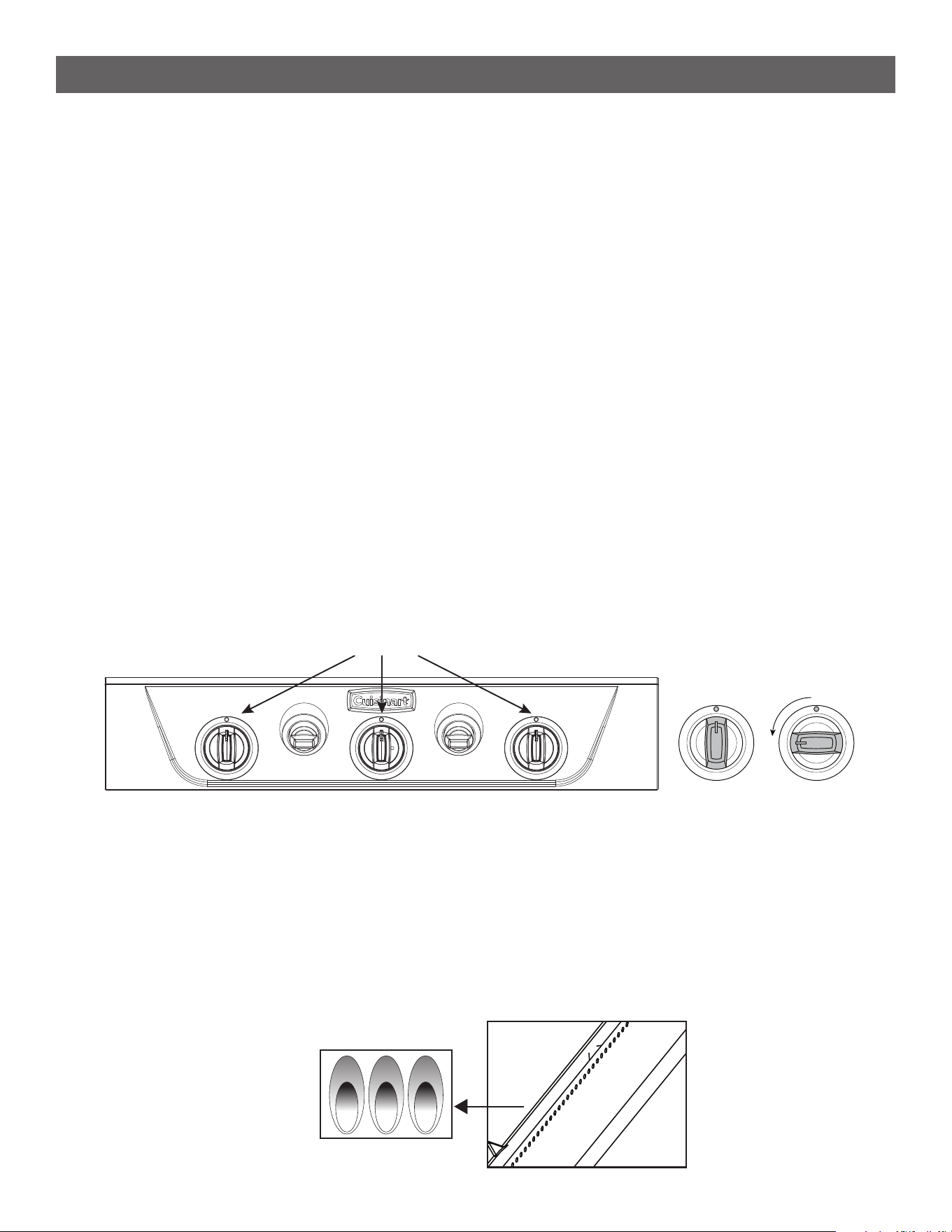
OPERATING INSTRUCTIONS
GETTING STARTED- OPERATION
--------------------------------------------------------------------------------------
OUTDOOR USE ONLY / NEVER LEAVE UNATTENDED
1. Make sure the propane cylinder is tightly threaded into the regulator. Also check that the burner knob is in the
“OFF” position.
2. Slowly turn the propane cylinder counterclockwise to open it. It is important to open the rst half turn slowly to
ensure safety shut off mechanisms are not triggered in the regulator. After the rst half turn it is ok to open it
the rest of the way at normal ow.
3. Open the hood. Each burner is equipped with its own electronic ignitor. When you press in each knob,
the ignitor will begin to click, like how your kitchen stove works. Press and turn each burner knob
counterclockwise until HIGH is displayed.
4. If Ignition does not occur in 3-5 seconds, turn the burner knob off. Wait 5 minutes before attempting to re-light
the burner. If a second attempt fails to ignite the burner, call our customer service team at 866-994-6390 for
assistance.
5. Burner will start in the HIGH position, adjust to desired power level by turning the knob counterclockwise.
6. The main burners also heat the broiler cabinet. There is no separate ignition.
7. Let the unit pre-heat for at least 10-15 minutes before beginning to cook.
8. To turn the appliance off rotate all burner knobs clockwise until the red indicator is pointing straight up, 12:00.
Visually inspect the burners to ensure there are no ames.
9. Close the LP cylinder valve by turning it clockwise until it stops.
FLAME CHARACTERISTICS
--------------------------------------------------------------------------------------
• Visually check ames on the burner to ensure the gas is combusting effectively. Flames should be blue with a
lighter blue cone in the center. The ames should be in contact with the burner and all burner ports should be
lit. Some orange at the tips is OK but if more than half the ame is orange and appears lazy, there could be an
issue with the air supply.
• The burners on this griddle are specially designed to enhance broiler performance. It is easiest to view them in
operation by looking up from the inside of the broiler chamber.
Burner Knobs
OFF HIGH / START

31
OPERATING INSTRUCTIONS
HOW TO SEASON YOUR GRIDDLE
--------------------------------------------------------------------------------------
A properly seasoned griddle surface creates a naturally non-stick cook top and helps prevent rusting.Season-
ing your griddle surface is essential for optimal performance and longevity. When you receive your griddle, it will
already have a thin layer of oil applied. This is to protect from rust during shipping.
1. Start by using warm soapy water and a towel to wash off the shipping oil.
2. Next, you’ll want to select a high smoke point oil.(e.g. Sunower Oil, Vegetable Oil, Soy Oil, Peanut Oil, Avo-
cado Oil)
3. Turn all burners on to HIGH and let the griddle heat for 10-15 minutes. The area above each burner on the
griddle surface will begin to darken. Once you see the darkened spots, turn the burners off.
4. Use paper towels to apply a thin coat of oil on the entire griddle surface with tongs or heat-resistant gloves to
avoid burning your hand. Turn on all burners to HIGH.
5. The oil will eventually begin to smoke. Leave it on HIGH until the smoke stops (about 15-20 mins). Once the
smoke is gone, you have passed the smoke point and can turn the burners off.
6. Repeat oil seasoning process 2-3 more times, until your griddle surface is a smooth, dark brown color.
HOW TO USE THE BROILER
--------------------------------------------------------------------------------------
• The three main burners that heat the griddle surface also heat the broiler cabinet. There is no separate ignition.
• If you are using the griddle, then the broiler will be “ON” by default. You will not use any extra fuel by using
both functions simultaneously.
• The 2 smaller knobs on the control panel control the Broiler Bafes.
• The Broiler Bafes direct heat down into the broiler cabinet for high-heat, open-ame broiling.
• When the knobs are turned to the BROIL setting, this will give you temperatures up to 600° F in the broiler
cabinet.
• When the knobs are turned to the TOAST/MELT setting, it will release heat from the broiler cabinet (about 75-
100 F), giving you lower temperatures to toast rolls or melt cheeses.
• Use the main burner control knobs to adjust temperature in the broiler cabinet as needed.
• Using the broiler will not compromise your griddle cooking performance.
• The Broiler Bafes do not close off all heat to the griddle plate. They simply direct additional heat down when
needed for broiling.
• The cooking rack can be adjusted between 3 height levels.
• Adjust the rack based on the cooking function you are using.
• Based on the height of what you are cooking, use the top 2 racks for BROIL.
• Use the bottom rack position for TOAST/MELT.
• Always keep the door closed when in use.
• For additional tips, tricks, and recipes for the broiler, scan the QR code on the back cover to access the prod-
uct page and download the Quick Start Guide and Recipe Booklet.

32
CLEANING AND CARE
--------------------------------------------------------------------------------------
Griddle Plate
• After you’ve nished cooking, use a squeeze bottle to add water to the hot griddle surface to create steam to
help break up debris and scrape down the surface. Scrape all the residue and remaining water into the grease
trap.
• Turn the griddle off and let the surface cool. While it cools, remove and clean out the grease trap. Do this after
each use to ensure you have no spillovers the next time.
• When the surface is cool, apply a thin coat of oil over the entire surface to maintain your seasoning. Store
your griddle in a cool, dry place. If you’re storing outside, cover the griddle to prevent water collecting on the
surface. Griddles are very resilient and, if they rust, can easily be restored. Use a steel scouring pad to remove
all rust from the surface and follow the seasoning steps again.
Griddle Plate Warping
• Warping occurs when the griddle surface is exposed to extreme temperature changes. This typically happens
when too much cool water is applied to the hot surface for cleaning.
• The griddle surface is made from carbon-steel and will naturally expand and contract during heating cycles to
allow for thermal expansion.
• As your griddle surface becomes accustomed to the heat, you may experience some warping during one of
your rst uses.
• Warping is normal and is something that can happen with any brand of griddle your purchase.
• Not every griddle surface will warp, but those that do could warp up to 5 times or more.
• When the griddle surface warps, turn the burners back on (if they were previously turned off) and allow the
surface to re-heat. The surface should level again with 20-30 minutes.
• If your griddle surface warps more than 5 times, please reach out to our customer service department for
troubleshooting and assistance.
There are a few things you can do to help prevent your griddle surface from warping:
1. Do not excessively preheat your griddle surface before beginning to cook, especially if you are going to be
applying cold food to the surface.
2. Use a squeeze bottle to apply water for cleaning as needed. Do not add large amounts of water to the surface
while cleaning.
3. Do not add frozen food to the hot griddle surface
Broiler Cabinet
• To clean the broiler cooking rack, use a steel wire brush or at edge steel scraper to remove any larger pieces
of debris.
• Scrape all debris off the Broiler Grease Pan and towards the grease drain hole in the center.
• Clean out the Grease Cup and replace it for next use.
CARE AND MAINTENANCE

33
MAINTENANCE
--------------------------------------------------------------------------------------
• There is very little care and maintenance needed for this Griddle which is designed and made of materials that
will last for many years with normal use.
• Following these instructions will improve the longevity and quality of cooking.
• Keep appliance area clear and free from combustible materials, gasoline, and other ammable vapors and
liquids.
• Keep the ventilation opening(s) of the cylinder enclosure free and clear from debris.
• It is recommended to disassemble the burner and clean both inside and outside at least twice a year and
especially after long storage. Thoroughly dry the inside and outside of the burner before reassembly. A clogged
burner can lead to a re beneath the appliance.
• When Griddle is not in use, turn the control knob and the knob on the propane cylinder to the “OFF” position,
then detach the regulator from the propane cylinder
• Keep area adjacent to the burner box clear of debris and free of anything ammable or combustible.
• Non-rechargeable batteries are not to be recharged. Batteries are to be inserted with the correct polarity.
Exhausted batteries are to be removed from the product. DO NOT DISPOSE OF BATTERIES IN A FIRE.
BATTERIES MAY EXPLODE OR LEAK.
• The burner components are factory-adjusted for optimal combustion. Please do not attempt to adjust the
burner. It is preset to the factory specications.
General Care
• All painted and stainless steel surfaces can be cleaned with warm soapy water and a soft sponge. We do not
recommend harsh scrubbers like steel wool on any of the surfaces as this can damage the paint and scratch
the stainless steel.
• Before each use ensure both grease cups are empty and clean. To easily clean the grease cups use our foil
liners (Item # CAP-6753 - Sold Separately) which can be disposed of when full. Two liners are provided with
this product and more can be purchased from our store. If not using a liner, use a paper towel and wipe out
any grease or debris into a garbage can.
• After the station is cool to the touch, we recommend using our weather resistant fabric cover to protect it
from the elements. For a perfect t use our custom t Griddler cover (Item # CGC–9224 – Sold Separately).
Griddles are very resilient and, if they rust, can easily be restored. Use a steel scouring pad to remove all rust
from the surface and follow the seasoning steps again.
CARE AND MAINTENANCE
34
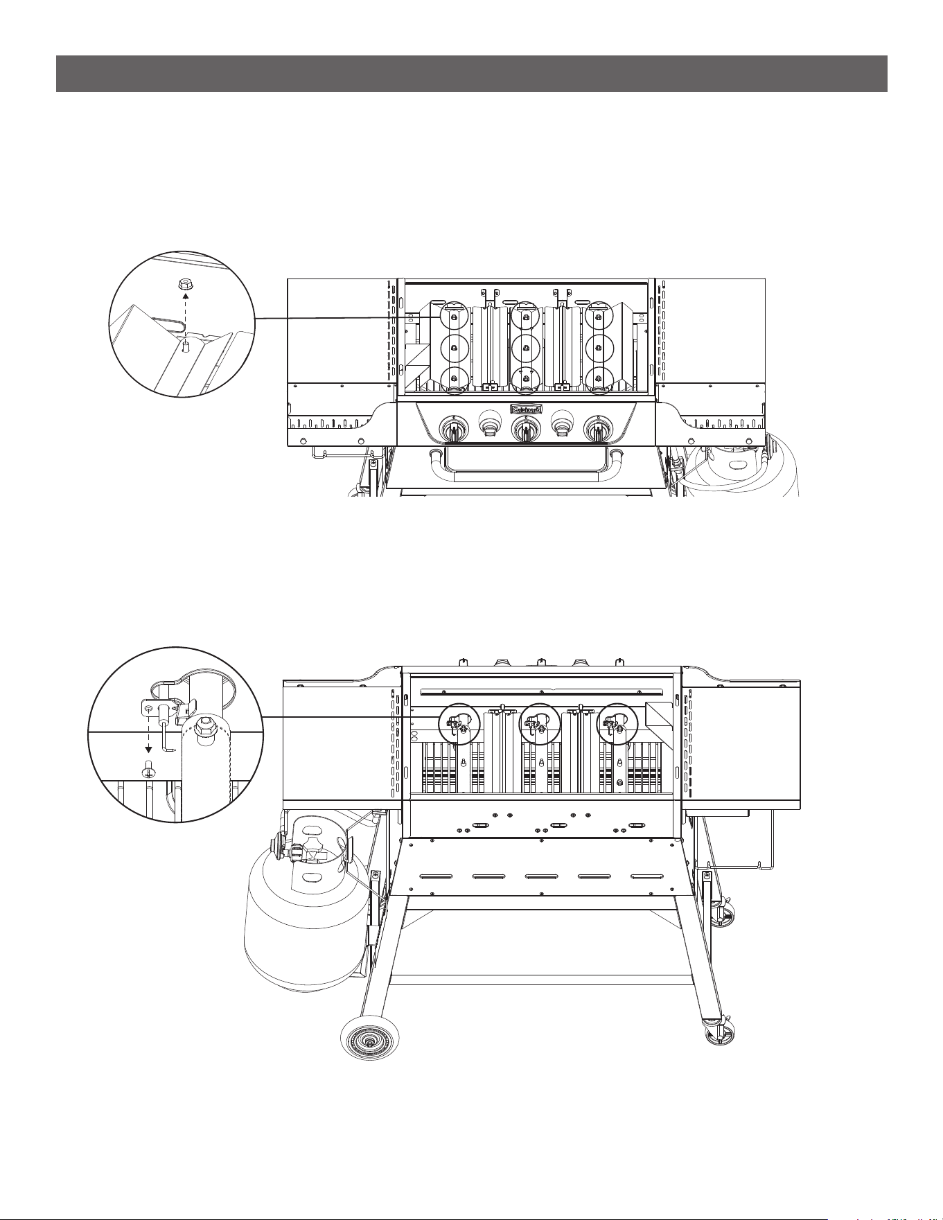
REPLACING YOUR BURNERS
STEP 1
--------------------------------------------------------------------------------------
• With the griddle plate removed, unscrew the nuts on the top of the ame tamers and remove them.
• Set the 3 ame tamers and 9 nuts aside to be reinstalled at the end.
CARE AND MAINTENANCE
STEP 2
--------------------------------------------------------------------------------------
• Towards the front of the griddle, remove the screw that secures the ignition electrode to the burner tubes.
Save the screw to be reinstalled later and carefully thread the electrode out of the burner.
• Leave the electrode hanging inside the rebox to be reinstalled later.
35
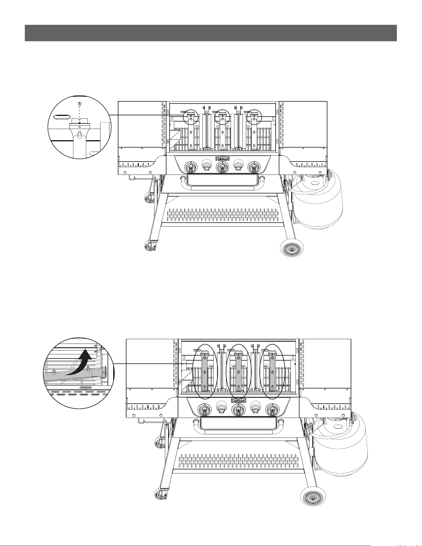
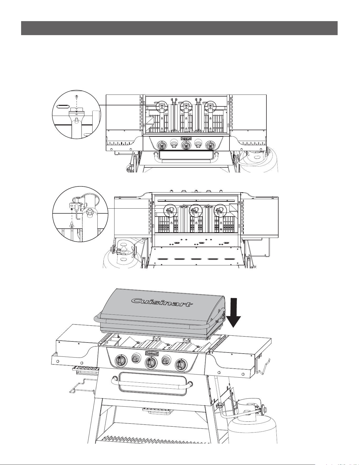
STEP 3
--------------------------------------------------------------------------------------
• Remove the screw at the back of the burner which secures it to the griddle re box.
CARE AND MAINTENANCE
STEP 4
--------------------------------------------------------------------------------------
• To remove the burners, lift the back up rst and then back the burner out of the hole in the front of the rebox.
36
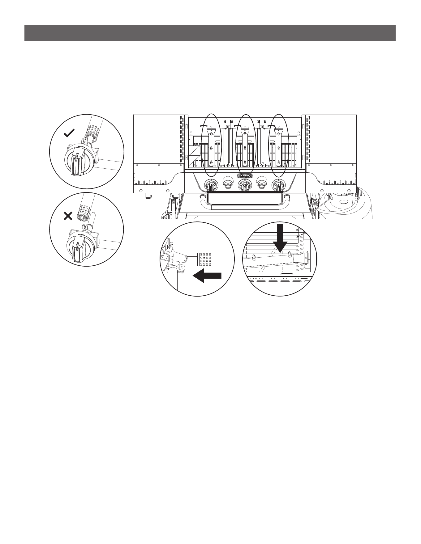
STEP 5
--------------------------------------------------------------------------------------
• To install a new burner, insert the round end of the burner into the hole at the front of the rebox. There is a
tubular section of the valve which should t perfectly inside the burner tube as you are inserting it.
• When it is all the way in, angle the back of the burner tube down so that it rests on the bracket.
CARE AND MAINTENANCE
37
STEP 6
--------------------------------------------------------------------------------------
• Secure the burner with the previously removed screw, reattach the electrode to each replaced burner, and
reinstall the ame tamers the same way they were disassembled.
• Place the griddle plate back on top of the re box and you are done.
CARE AND MAINTENANCE
38
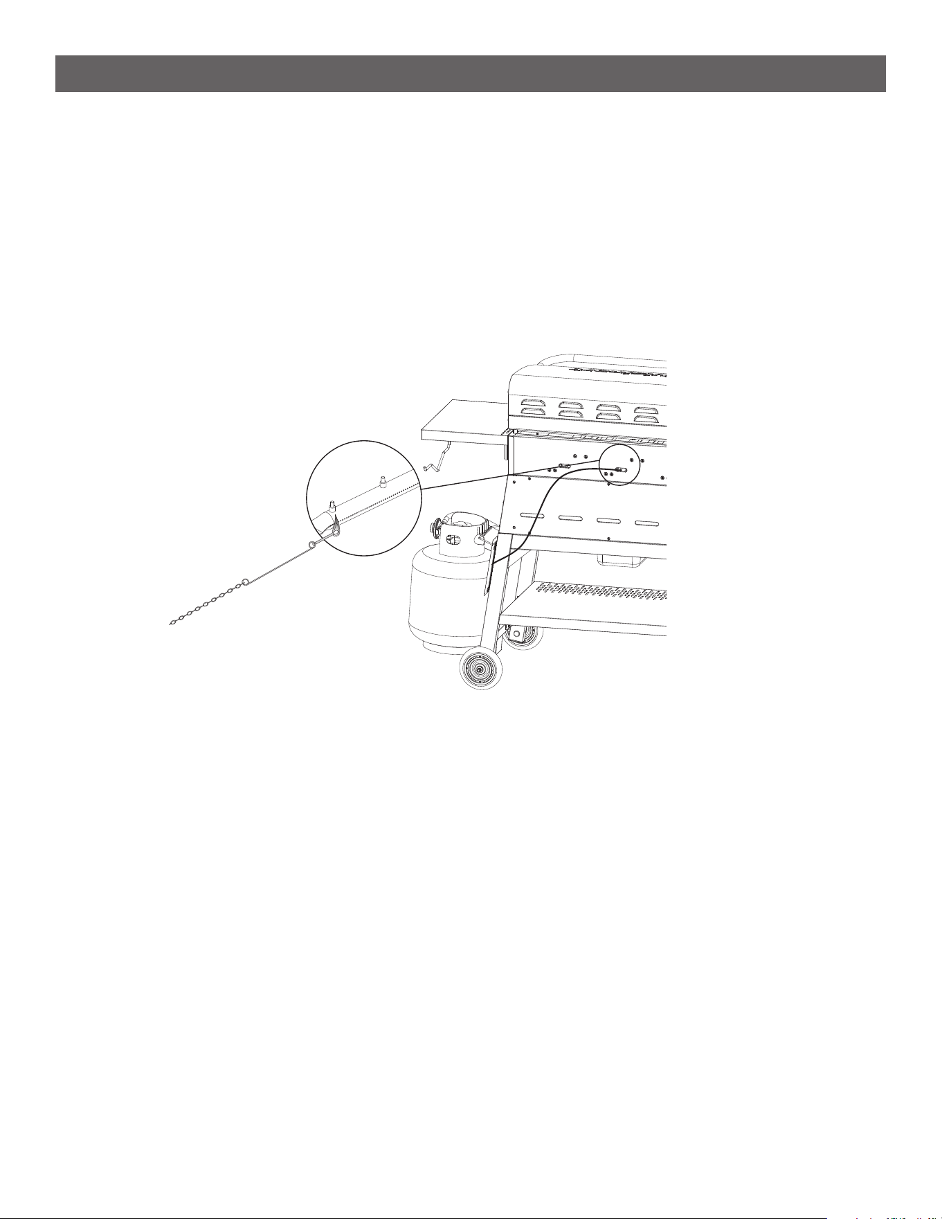
MATCH LIGHT INSTRUCTIONS
If for any reason you want to use a match to start this product please follow these instructions:
• Open the lid
• Verify the propane tank is installed and when turning the burner valve, gas ows through the burner.
• Locate the match holder which is installed on the top of the Back Right Leg.
• Slip a match into the ring clip at the end of the match holder.
• Strike the match.
• Turn the burner knob to the START/HIGH position then move the lit match towards the burner ports through
the gaps at the back of the griddle. Burner will light.

39
TROUBLE SHOOTING
WARNING
Spiders and insects can nest inside the burners of the Griddle and disrupt gas ow. This very dangerous
condition could cause a re behind the valve panel, thereby damaging the Griddle and making it unsafe
for operation. Inspect the Griddle at least twice a year.
When to Look for Spiders
You should inspect the burner at least twice a year or immediately after any of the following conditions occur:
• The smell of gas in conjunction with burner ames appearing yellow.
• The product does not reach temperature.
• The product heats unevenly.
• The burner makes popping noises.
BEFORE CALLING FOR SERVICE
If the Griddle does not function properly, use the following checklist before contacting customer service.
Problems What To Do
• Griddle won’t turn on/ ignite
• Griddle ames are yellow or irregular
• Griddle takes too long to heat up
• Ensure the propane tank is full and the valve is fully open.
• Check if the burner knobs are set to the “Off” position before
lighting, then turn them to “Ignite.”
• Inspect the ignition system (igniter button, electrode, and wires)
for any damage or debris.
• Test the ignition system by pressing the igniter button while listen-
ing for a clicking sound. If there’s no sound, the igniter might need
to be replaced.
• Inspect the burner ports for blockages from dirt or debris and
clean them if necessary.
• Try manually lighting the grill with a long match or lighter through
the match-light hole.
• Uneven heating
• Temperature inconsistency
• Preheat the griddle evenly for the recommended time before
cooking.
• Check for any debris or residue under the griddle surface that
could interfere with heating.
• Ensure that the griddle is placed on a level surface.
• Inspect the propane tank or gas line for leaks or low fuel.
• Food sticking to the griddle • Make sure the griddle is properly preheated before placing food
on it.
• Apply a light coat of oil or non-stick spray before cooking.
• Clean the griddle thoroughly after each use to remove any lef-
over residue.

40
TROUBLE SHOOTING
Problems What To Do
• Griddle smokes excessively • Ensure that you’re using the correct cooking oil (high smoke point
oils like canola or peanut oil are preferred).
• Clean the griddle after each use to remove any leftover grease or
food particles that can burn and cause smoke.
• If the griddle is too hot, reduce the heat to avoid burning oil and
food.
• Broiler is not getting hot • Ensure the propane tank is full and the valve is fully open.
• Inspect the ignition system (igniter button, electrode, and wires)
for any damage or debris.
• Test the ignition system by pressing the igniter button while
listening for a clicking sound. If there’s no sound, the igniter might
need to be replaced.
• Inspect the burner ports for blockages from dirt or debris and
clean them if necessary.
• Ensure the Broiler Bafes are closed.
• Unable to rotate Broiler Bafes • Inspect Bafes for any damages.
• If damaged, call customer care for replacement.
• Inspect for blockages from dirt or debris aroundthe bafe rod
and clean them if necessary.
41
EXPLODED VIEW & PARTS LIST
47
48
67
68
48
70
69
58
71
72
83
83
27
28
31
33
34
35
36
37
59
60
61
58
52
51
49
62
63
64
65
74
73
56
57
54
55
53
82
84
85
88
89
77
88
87
81
86
90
85
84
80
80
79
78
75
76
78
77
50
3
1
3
7
8
9
4
4
2
10
11
38
39
40
6
12
18
19
43
41
44
45
46
42
22
20
13
21
14
40
40
40
23
24
25
26
29
32
15
16
17
5
66
30
42
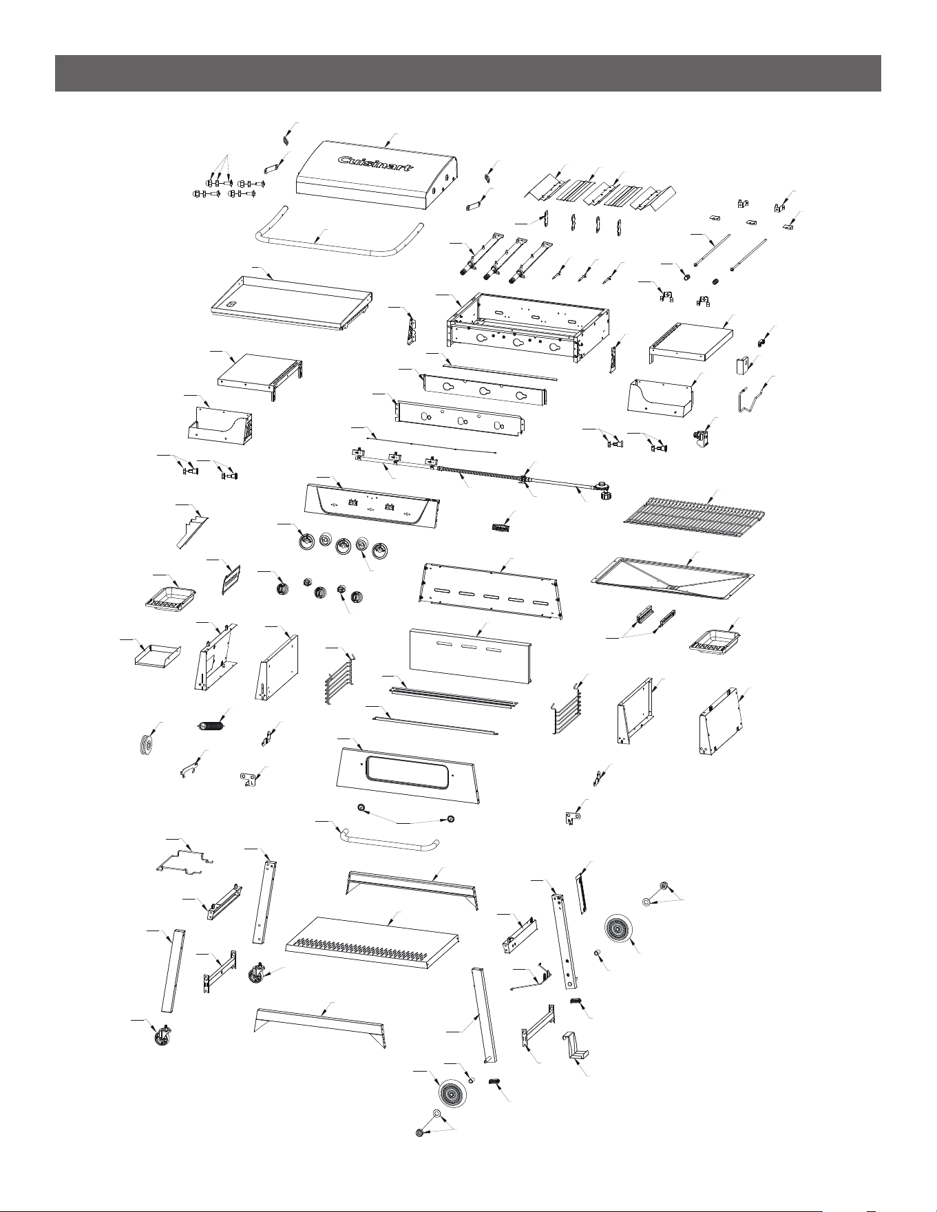
EXPLODED VIEW & PARTS LIST
For replacement parts, call our customer service department 866-994-6390, 9 a.m.-5 p.m., EST, Monday-Friday
or email [email protected] NOTE: Not all parts are replaceable.
Part Description Quantity
1 Lid assembly 1 pc
2 Lid handle assembly 1 pc
3 Lid hinges A 2 pc
4 Lid hinges B 2 pc
5 Lid axle assembly 4 pc
6 Griddle assembly 1 pc
7 Flame tamer 2 pc
8 Broiler bafe 2 pc
9 Flame tamer 1 pc
10 Broiler bafe rear bracket 2 pc
11 Burner support 3 pc
12 Broiler bafe axle 2 pc
13 Reector 4 pc
14 Burner assembly 3 pc
15 Ignition pin A (L=880) 1 pc
16 Ignition pin B (L=680) 1 pc
17 Ignition pin C (L=480) 1 pc
18 Flame tamer rod spring 2 pc
19 Broiler bafe front bracket 2 pc
20 Firebox assembly 1 pc
21 Control panel left side panel 1 pc
22 Control panel right side panel 1 pc
23 Front rain sheild 1 pc
24 Control panel heat shield B 1 pc
25 Control panel heat shield A 1 pc
26 Switch wire set 1 pc
27 Valve and hose assembly 1 pc
28 Flex gas line 1 pc
29 Adaptors xing plate 1 pc
30 Adaptor 1 pc
31 Hose and regulator 1 pc
32 Control panel assembly 1 pc
33 Logo badge 1 pc
34 Knob bezel 3 pc
35 Broiler bafe knob bezel 2 pc
36 Knob set 3 pc
37 Broiler bafe knob set 2 pc
38 Left side table assembly 1 pc
39 Left side panel 1 pc
40 Hook set 4 pc
41 Right side table 1 pc
42 Right side table panel 1 pc
43 Towel xing plate 1 pc
44 Pulse ignitor xing plate 1 pc
45 Towel rod 1 pc
43
EXPLODED VIEW & PARTS LIST
Part Description Quantity
46 Pulse ignitor (1 out 3) 1 pc
47 Grease guiding xing plate 1 pc
48 Grease cup 2 pc
49 Grease box bracket B 1 pc
50 Maintain cover 1 pc
51 Broiler left side panel 1 pc
52 Broiler left side inner panel assembly 1 pc
53 Alex wheel 1 pc
54 Tension springs 1 pc
55 Broiler door hinges 1 pc
56 Alex left lower xing plate 1 pc
57 Alex left upper xing plate 1 pc
58 Cooking grid support assembly 2 pc
59 Broiler rear panel assembly 1 pc
60 Broiler rear panel inner plate 1 pc
61 Broiler upper heat shield 1 pc
62 Broiler lower heat shield 1 pc
63 Front door assembly 1 pc
64 Broiler door handle bezel 2 pc
65 Broiler door handle assembly 1 pc
66 Cooking grid, broiler 1 pc
67 Grease tray 1 pc
68 Grease cup bracket A 2 pc
69 Broiler right side inner panel assembly 1 pc
70 Broiler right side panel assembly 1 pc
71 Alex right lower xing plate 1 pc
72 Alex right upper xing plate 1 pc
73 Garbage bag bracket 1 pc
74 Left rear cart leg assembly 1 pc
75 Left upper cart brace assembly 1 pc
76 Left front cart leg assembly 1 pc
77 Left upper cart brace assembly 2 pc
78 Caster 2 pc
79 Cart bottom panel 1 pc
80 Cart middle brace assembly 2 pc
81 Cart rear leg assembly 1 pc
82 Lighting rod 1 pc
83 Cart wheel nuts set 2 pc
84 Wheel 2 pc
85 Axle sleeves 2 pc
86 Cart right upper brace assembly 1 pc
87 Gas bottle xing wire 1 pc
88 Cart leg 2 pc
89 Gas bottle xing plate 1 pc
90 Right front cart leg assembly 1 pc

44
Questions, problems, missing parts? Before returning to your retailer,
call our customer service department at 866-994-6390, 9 a.m.-5 p.m.,
EST, Monday-Friday or email [email protected]
Visit our website: www.cuisinart.com
2410
Model#CGG-9020
Cuisinart Outdoors a division of Conair LLC
Newton, MA 02466
WARRANTY AND REPLACEMENT PARTS
• This warranty covers defects in parts and workmanship for a period of 3 years from the original purchase date.
• Any damage claim regarding the enameling must be submitted within 30 days of purchase to be covered by
the warranty.
The following conditions are NOT covered by this warranty:
• Unevenness and color variations in the coated surfaces.
• Damage caused by improper assembly or disregard of the manual.
• Use of spare parts not supplied by manufacturer.
• Damage resulting from modications or inappropriate use.
• Abuse of the griddle.
• Damage caused by improper maintenance or repairs by an unauthorized person.
Limitations and exclusions:
1. This warranty applies only to the original purchaser and may not be transferred.
2. If you can not verify the purchase date of the griddle the warranty period will begin on the date the griddle
was manufactured.
3. Replacement or repair parts are warranted for the remaining period of the original part warranty.
Your obligations:
• This griddle must be assembled, installed, operated and maintained in accordance with all applicable codes
and the instruction manual furnished with this griddle. You must keep an invoice, cancelled check or payment
record to verify the purchase date of the griddle.