www.peavey.com
PVXp
™
10 Bluetooth®
Powered Speaker System
Operating
Manual

FCC/ICES Compliancy Statement
This device complies with Part 15 of the FCC. Operation is subject to the following two conditions: (1) this device may
not cause harmful interference, and (2) this device must accept any interference received, that may cause undesired
operation.
Le présent appareil est conforme aux CNR d’lndustrie Canada applicables aux appareils radio exempts de
licence. L’exploitation est autorisée aux deux conditions suivantes: (1) I’appareil ne doit pas produire de
brouillage, et (2) I’utilisateur de I’appareil doit accepter tout brouillage radioélectrique subi, même si le
brouillage est susceptible d’en compromettre le fonctionnement.
Warning: Changes or modifications to the equipment not approved by Peavey Electronics Corp. can void the
user’s authority to use the equipment.
Note – This equipment has been tested and found to comply with the limits for a Class A digital device,
pursuant to Part 15 of the FCC rules. These limits are designed to provide reasonable protection against
harmful interference when the equipment is operated in a commercial environment. This equipment
generates, uses and can radiate radio frequency energy and, if not installed and used in accordance with the
instruction manual, may cause harmful interference to radio communications. Operation of this equipment in
a residential area is likely to cause harmful interference in which case the user will be required to correct the
interference at their expense.

Introduction
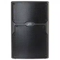
ank you for purchasing the powered Peavey® PVX™p 10 Bluetooth® speaker system. e PVX™p 10 Blue-
tooth® features an reliable bi-amped power section that provides a total of 520 Watts of peak dynamic power
with DSP based compression and limiting. Featuring a 10” heavy-duty woofer with a 2 3/8 inch voice coil
and 50 ounce magnet, and the RX™10 compression driver with a 1 inch titanium diaphragm on a 100 degree
horizontal x 60 degree vertical pattern asymmetrical horn. e PVX™p 10 Bluetooth® provides two channels
with a balanced input via a combination jack that accepts balanced TRS 1/4 inch input as well as a balanced
XLR input. A switch is provided to change between line level gain and mic level gain. A third channel is for a
Bluetooth® source, or alternatively a 1/8” AUX input jack. Each channel has an adjustable Level control, and a
three-band EQ section. ere is a balanced output, a Male XLR, that can feed the mixed signals from the three
channels out to another component. A front bae LED indicator that can be set to light when power is on, and
when the “so-limiting” DDT circuit is activated, or turned o altogether. e LCD display and EQ presets,
along with other DSP operating parameters are accessed via a one-knob selector.
Features
* Two-way bi-amped sound reinforcement enclosure
* 10” heavy-duty woofer with 2 3/8” voice coil & 50 oz. magnet
* RX™10 compression driver, with 1 inch titanium diaphragm
* Reliable fan-cooled power amps with DSP protection
* Total of 520W peak dynamic power
* DSP control for precise crossover, EQ and limiting functions
* DSP I/O is at 48 kHz and 24 bits, internal processing is 56 bit double-precision
* Peavey’s Quadratic roat Waveguide™ technology, 100 by 60 degree coverage
* Asymmetrical horn aims the sound down 10 degrees, at the audience, not over their heads
* Bluetooth® input is via a dedicated input channel
* Analog input is via a combo female XLR and 1/4” TRS phone jack with balanced input
* ree channels in total, two for analog, and one for Bluetooth or AUX input via a 1/8” jack
* Each channel has a level control and a 3-band EQ section to adjust and shape the input signals
* Mix/ru Output is via a male XLR jack
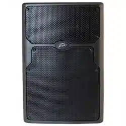
* Durable plastic injection-molded trapezoidal enclosure
* Extra angled section on right side allows oor monitor use
* Full-coverage heavy-duty perforated steel grilles, with powder coat nish
* Pole mount molded-in for 1 3/8” diameter poles
* Top and bottom ying point inserts
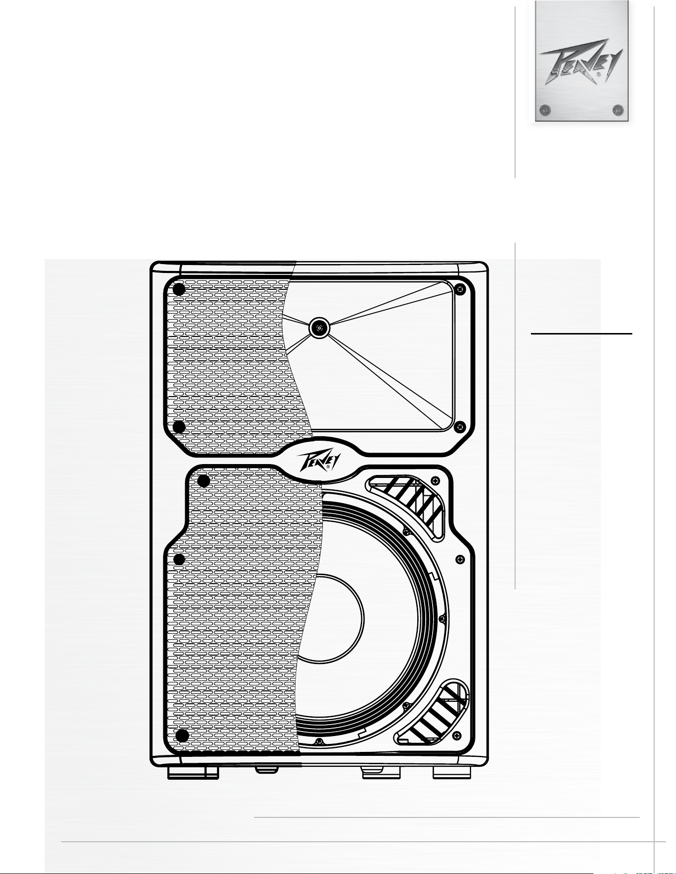
Description
e PVX™p 10 Bluetooth® is a two-way sound reinforcement system based on a heavy-duty Pro 10 10” woofer
and a RX™10 titanium diaphragm dynamic compression driver mounted on a 100 by 60 degree coverage Qua-
dratic roat Waveguide™. It’s sleek, modern appearance coupled with excellent performance, oer a superb
overall package.
e lightweight yet rugged injection-molded plastic enclosure with molded-in stand mount cup facilitates
portable use for live music or PA sound. e trapezoidal cabinet has two handles for ease of portability, and an
extra 45-degree angled section on the right side to allow use as a oor monitor. Four sets of ying/mounting
ENGLISH

points, two sets on the top, two sets on the bottom, and one single insert on the rear near the bottom, with a total
of 13 cabinet inserts, provide for the ultimate in installation exibility. A pair of black powder coated perforated
steel grilles provides driver protection and a professional appearance.
e heavy-duty 10” woofer has a 2 3/8” voice coil diameter, and a 50 oz. magnet for chest-pounding bass. e
RX™10 compression driver tweeter is coupled to a Quadratic roat™ constant directivity waveguide. e Qua-
dratic roat Waveguide™ is an original Peavey® design, with smooth, even response, low distortion and good
high frequency dispersion. is horn has an asymmetrical vertical polar response, aiming the main energy lobe
down 10 degrees, so it is aimed at the audience, instead of over their heads. e vertical polar pattern is +20
degrees, -40 degrees. is helps reduce ceiling reections for greater clarity and gain before feedback.
e PVX™p 10 Bluetooth® speaker system power ampliers providing the bi-amplication are low-distortion
reliable fan-cooled units providing a total of 520W peak dynamic power for the system.
ere is 400W peak dynamic power for the woofer, and 120W peak dynamic power for the tweeter. e power
supply for both amps is a switch mode type for low weight and high eciency. Both ampliers feature sophis-
ticated DSP based signal compression, which virtually eliminates audible power amplier clipping. Cooling is
provided via a low-noise fan, for reliable operation under any conditions.
Input for two of the three input channels is via a combo female XLR and 1/4” TRS phone jack with balanced
input to the preamp/EQ electronics, and a level control. For these two channels, a switch is provided to change
between line level gain and mic level gain. A third channel is for a Bluetooth® source, or alternatively a 1/8” AUX
input jack. Each channel has an adjustable Level control knob, and also a three-band EQ section that is accessi-
ble via the DSP menu Push knob. ere is a balanced output, a Male XLR, that can feed the mixed signals from
the three channels out to another component. is output allows linking of additional speaker systems, or feed
of the signal to a powered subwoofer, etc.
e cabinet of the PVX™p 10 Bluetooth® speaker system has multiple mounting y points, providing outstanding
versatility in permanent install use. A pair of widely spaced M8 inserts is molded-in on the top, and a pair on
the bottom, and a set of four M8 inserts is available on the top, on the bottom for use with the Versamount™ 70,
and one M8 on the rear near the bottom. is is a total of 13 mounting inserts in all. All of these inserts have
retaining hardware on the inside of the plastic cabinet, providing a more reliable and safe mode of mounting the
cabinet.
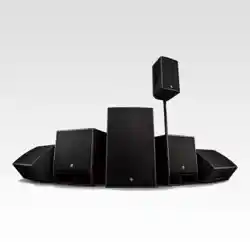
Applications
e Peavey PVX™p 10 Bluetooth® has a variety of applications such as sound reinforcement, public address, side
ll system, karaoke or musical playback.
e multiple y points make use as a permanent install system very convenient with lots of installation exibility.
A typical signal source for the line-level inputs of the Peavey PVX™p 10 Bluetooth® would be a sound reinforce-
ment mixing console (mixer) or the output from a CD player, MP3 player or tape deck. e Bluetooth® link
provides for many modern devices to link to the system, such as smart phones, digital mixers, etc. A typical
dynamic microphone can be connected directly via the XLR input and used as well.
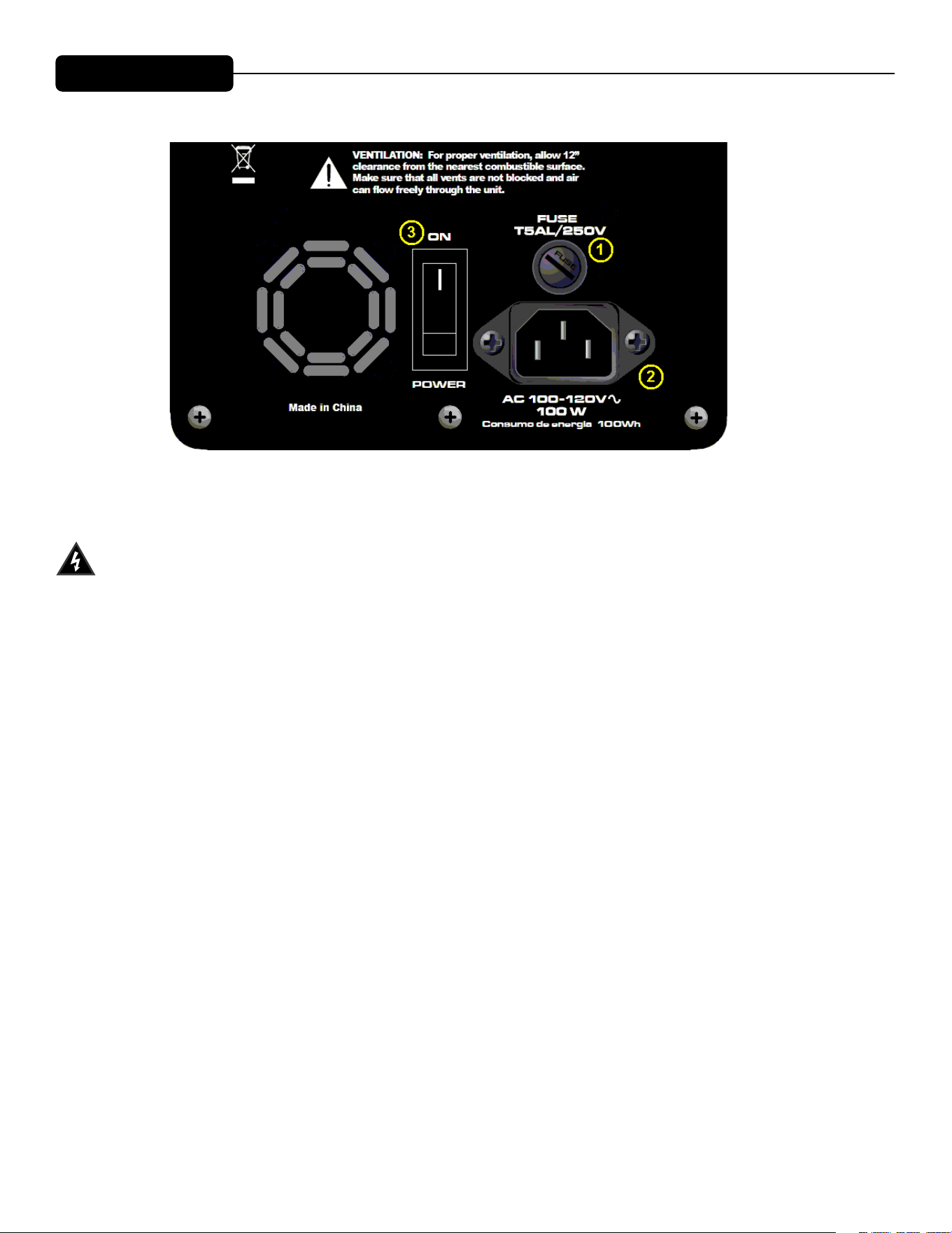
LOWER REAR PANEL
FUSE (1)
The unit is AC power line fuse protected from overloads and fault conditions with a slow-blow 5 x
20mm 250V fuse. This fuse is located within the cap of the fuse enclosure just above the IEC power cord
connection. If the fuse fails, THE FUSE MUST BE REPLACED WITH THE SAME TYPE AND VALUE IN
ORDER TO AVOID DAMAGE TO THE EQUIPMENT AND TO PREVENT VOIDING THE WARRANTY!
The fuse in the PVX™p 10 Bluetooth® can be replaced with a time-delay type 5 x 20 mm size 250V rated fuse.
For 100-120VAC operation, a fuse rated at 5 amps should be used. In the USA, types GDC, GMC, 215, 218, and
477 cartridge-style 5 x 20 mm size fuses with a 5 amp 250V rating can be used. The fuse should conform to the
international fuse classification “T5AL”.
For the Export model, using an input power voltage range of from 220VAC to 240VAC, use a 2.5 amp rated,
250V 5 x 20 mm cartridge type time-delay fuse, which conforms to the international fuse classification
“T2.5AL”.
If the unit continues to blow replacement fuses, do not keep replacing them- it should be taken to a qualified
service center for repair.
To replace the fuse, be sure to remove the IEC power cord from the IEC socket (2).
Remove the cap to the fuse enclosure (1) using a flat blade screwdriver tip inserted into the fuse cap slot. Push
the cap in and turn the cap CCW and unscrew the cap out until it comes free from the rear portion of the
holder. The blown fuse should come out with the cap.
Remove the blown fuse and replace it with the proper type per instructions previously supplied. Then, once the
new fuse has been put in place, re-insert the fuse enclosure cap, push in and screw the cap in CW, and make
sure it is fully seated.
Before re-attaching the IEC power cord to the IEC socket, make sure the Power switch is in the OFF position,
so that intermittent contact of the IEC cord while it is being connected will not unduly stress the amplifier or
the fuse.
Now re-attach the IEC power cord, and you can then use the Power switch (3) to turn the unit on.

IEC POWER CORD CONNECTION (2)
is receptacle is for the IEC line cord (supplied) that provides AC power to the unit. It is very important
that you ensure the PVX™p 10 Bluetooth® has the proper AC line voltage supplied. You can nd the proper
voltage for your PVX™p 10 Bluetooth® printed next to the IEC line (power) cord on the rear panel of the unit.
Please read this guide carefully to ensure your personal safety as well as the safety of your equipment. Never
break o the ground pin on any equipment. It is provided for your safety. If the outlet used does not have a
ground pin, a suitable grounding adapter should be used and the third wire should be grounded properly. To
prevent the risk of shock or re hazard, always be sure that the mixer and all other associated equipment are
properly grounded.
ON-OFF SWITCH (3)
This rocker switch supplies AC power to the PVX™p 10 Bluetooth® when switched to the ON position. The ON
position is with the top side of the switch pushed “in” or nearly flush with the rear panel.
UPPER REAR PANEL
INPUTs (4)
e line-level inputs are of the medium impedance balanced type. For channels 1 and 2 (4a and 4b), the jack is a
combo female XLR and 1/4” TRS connector. For channel 3 (4c), the optional AUX input jack is a 1/8”phone type.
Otherwise, channel 3 is the Bluetooth input channel when the PVX™p 10 Bluetooth® is linked with a Bluetooth
audio device. Sensitivity of the combo jacks is 0.50 volts for full output, and 0.18 volts for channel 3 (4c). See the
Level Control Adjustment section below for more details on the input sensitivity with a range of DSP mixer gain
settings.
Level (5)
Controls the gain or output level of the input signal. It is used to directly set the system output level for a given
input channel input signal. All three channels can be mixed together, and made available at the Output jack (7)
MIC/LINE switch (6)
ese control the gain of the Channel 1 (4a) and Channel 2 (4b) to switch from line level gain to mic gain
levels. Gain is increased 40 dB when the switch is in the MIC position. DO NOT FEED A LINE LEVEL
SIGNAL INTO THE INPUT WITH THE MIC/LINE SWITCH IN THE MIC POSITION! e analog input
circuitry and the DSP system will overload and cause severe distortion that can not be removed by turning
down the Level control !
OUTPUT jack (7)
is jack is intended for the use of linking multiple PVX™p 10’s in a line or to provide a feed to a powered sub-
woofer, or other electronics that needs to receive a full range version of the input signal. e connector is a male
XLR jack.
Loudspeaker System Specifications
6
REAR PANEL
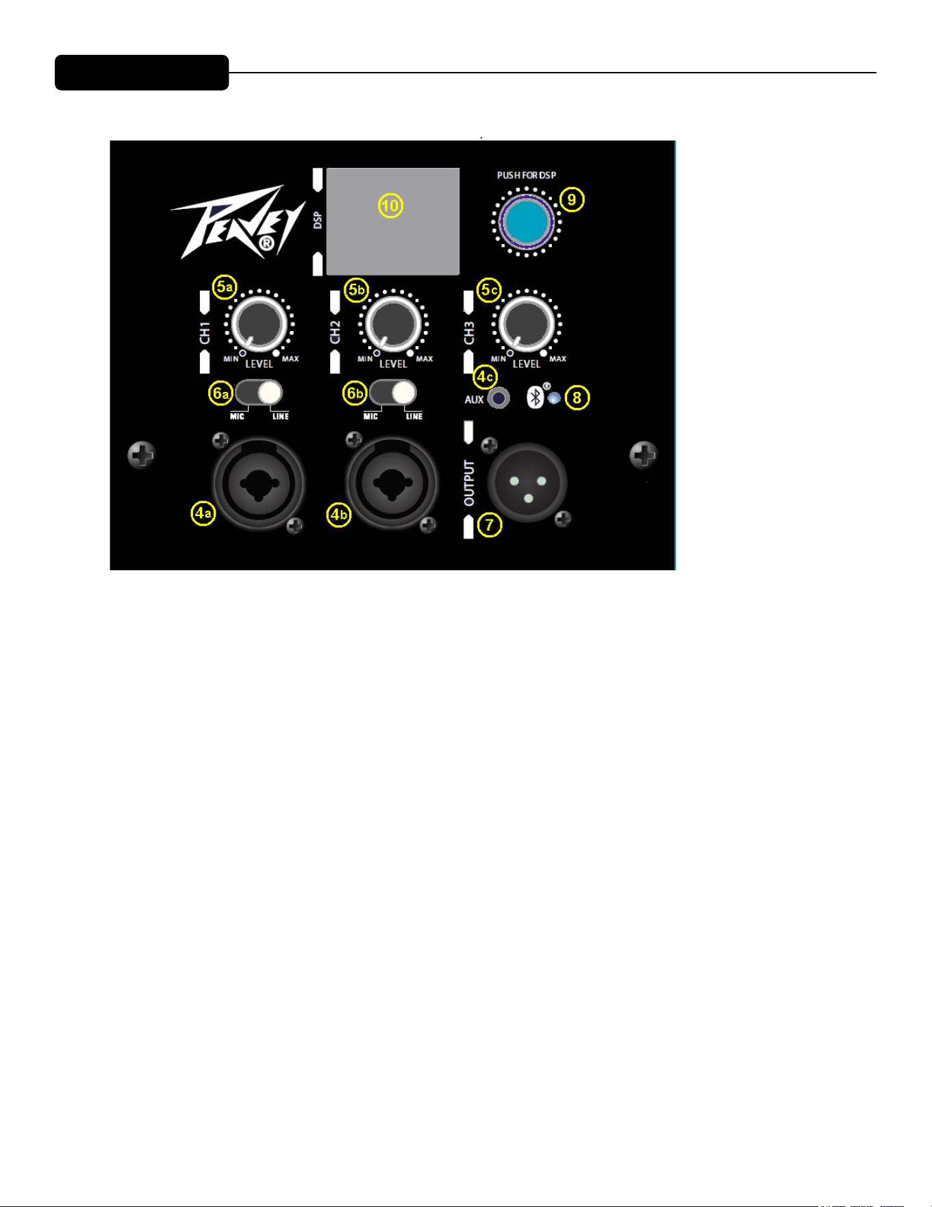
TOP – OPERATING CONTROLS, INPUTS & OUTPUTS
INPUTS (4)
The line-level inputs are of the medium impedance balanced type. For channels
1 and 2 (4a and 4b), the jack is a combo female XLR and 1/4" TRS connector.
For channel 3 (4c), the optional AUX input jack is a 1/8"phone type. Otherwise,
channel 3 is the Bluetooth input channel when the PVX™p 10 Bluetooth® is
linked with a Bluetooth audio device..
Sensitivity of the combo jacks is 0.50 volts for full output, and 0.18 volts for
channel 3 (4c). See the Level Control Adjustment section below for more
details on the input sensitivity with a range of DSP mixer gain settings.
LEVEL (5)
Controls the gain or output level of the input signal. It is used to directly set the
system output level for a given input channel input signal. All three channels can
be mixed together, and made available at the Output jack (7)
MIC/LINE Switch (6)
These control the gain of the Channel 1 (4a) and Channel 2 (4b) to switch from
line level gain to mic gain levels. Gain is increased 40 dB when the switch is in
the MIC position. DO NOT FEED A LINE LEVEL SIGNAL INTO THE INPUT
WITH THE MIC/LINE SWITCH IN THE MIC POSITION! The analog input
circuitry and the DSP system will overload and cause severe distortion that can
not be removed by turning down the Level control !

CAUTIONS
Bluetooth® LED (8)
Illuminates blue when the Bluetooth® channel has been activated. See the Bluetooth® section for more informa-
tion.
Push for DSP (9)
is knob accesses the DSP system user control functions, which include a wide variety of trims and adjust-
ments to the system, and to individual input channels, etc. See the DSP Menu section for more details.
LCD Screen for DSP Menu (10)
is screen displays the DSP menu options when the Push for DSP knob (9) is accessed and operated. See
the DSP Menu section for more details.
Not shown in the above rear panel diagram is a front bae LED which can be switched to OFF, ON (blue)
when power is applied, and LIMIT to indicate when compression and limiting are occurring by ashing
RED. is function is controlled by accessing the DSP system functions via the Push for DSP Knob (9).
Loudspeaker System Specifications
7
OUTPUT jack (7)
This jack is intended for the use of linking multiple PVX™p 12's in a line or to
provide a feed to a powered subwoofer, or other electronics that needs to
receive a full range version of the input signal. The connector is a male XLR
jack.
Bluetooth® LED (8)
Illuminates blue when the Bluetooth® channel has been activated. See the
Bluetooth® section for more information.
Push for DSP (9)
This knob accesses the DSP system user control functions, which include a wide
variety of trims and adjustments to the system, and to individual input channels,
etc. See the DSP Menu section for more details.
LCD Screen for DSP Menu (10)
This screen displays the DSP menu options when the Push for DSP knob (9) is
accessed and operated. See the DSP Menu section for more details.
Not shown in the above rear panel diagram is a front baffle LED which can be
switched to OFF, ON (blue) when power is applied, and LIMIT to indicate when
compression and limiting are occurring by flashing RED. This function is
controlled by accessing the DSP system functions via the Push for DSP Knob
(9).
OPERATING INSTRUCTIONS
Cautions
The unit must be disconnected from the AC power source before any
work is done on it. Refer all servicing to qualified service personnel.
The back plate can become hot to the touch. Do not block or cover the fan or
the exhaust louvers from ventilation. There must be a minimum of 4” of space
behind the fan. Do not allow the airflow to be become blocked by objects such
as curtains or drapes, thermal building insulation, etc. It is recommended that
the rear of the PVX™p 10 Bluetooth® not be placed in a closed space or a
space that has no fresh, cool airflow.
Be sure to keep the microphone away from the front of the speaker after
connecting it to the input, and while setting the microphone level, or very loud
feedback will occur! Damage to the system is likely if this occurs!
UPPER REAR PANEL

Loudspeaker System Specifications
8
DO NOT connect the inputs of the PVX™p 10 Bluetooth® to the output
of a power amplifier. The inputs are meant to be driven from a line-level strength
signal.
DO NOT remove the protective metal grilles.
WARNING! The PVX™p 10 Bluetooth® is very efficient and powerful! This
sound system can permanently damage hearing! Use extreme care setting the
overall maximum loudness!
The apparent sound level of the PVX™p 10 Bluetooth® can be deceiving due to
its clear, clean sound output. The lack of distortion or obvious distress can make
the sound level seem much lower than it actually is. This system is capable of
SPL in excess of 123 dB at 1 M from the speaker!
Flying the PVXp™10 Bluetooth®
IMPORTANT SAFETY INFORMATION FOR THE MOUNTING AND FLYING OF
THE PEAVEY PVX™p 10 BLUETOOTH®
CAUTION: Before attempting to suspend this speaker, consult a certified
structural engineer. Speaker can fall from improper suspension, resulting in
serious injury and property damage. Other enclosures may NOT be suspended
below one, nor should additional weight be suspended from one of these units.
Use only the correct mating hardware. All associated rigging is the responsibility
of others.
Maximum enclosure angle from vertical hang is 30 degrees.
Always use a suitable safety chain or wire rope, attached to an unused group of
fly points or to the cabinet as directed by a certified structural engineer, and
firmly attached to a suitable structural member as indicated by a certified
structural engineer.
The recommended range of torque for the mounting bolts is 3.5 to 4.0 foot-lbs.
(4.75 to 5.42 N-m). DO NOT OVERTIGHTEN ! If an insert spins free, it has
been damaged, and the cabinet can not be safely flown from that set of inserts!
Never transport the cabinet while mounted on an array bracket or other mounting
bracket, this may unduly stress the mounting inserts.
The use of threadlocker (blue type/medium strength) on the mounting bolts is
recommended, as are the appropriate lockwashers, to insure that the mounting
hardware will not vibrate loose over time.
OPERATING INSTRUCTIONS

Loudspeaker System Specifications
9
GROUPING OF INSERT SETS
Group A
A set of two widely spaced M8 inserts on the top, designed to hang the cabinet
using the proper eyebolts.
Group B
A set of two widely spaced M8 inserts on the bottom, designed to hang the
cabinet using the proper eyebolts.
Group C
A set of four M8 inserts on the top, designed to be used with the Peavey
Versamount™ 70 mounting bracket.
Group D
A set of four M8 inserts on the bottom, designed to be used with the Peavey
Versamount™ 70 mounting bracket.
For Group A and B, always use both inserts as a pair; NEVER use just one insert
to fly a cabinet!
For Group C, and D, Always use all four inserts of a given group as a set;
NEVER use just one insert to fly a cabinet! The four insert groupings are meant
to have all four inserts used at once within a group.
Group D should only be used with the Versamount™ 70 oriented beneath the
cabinet, and at an angle less than 30 degrees from vertical.
SPECIFICATIONS FOR INSERT MATING HARDWARE
Group A and Group B should use an M8 forged steel shoulder-type lifting
eyebolt, which meets the requirements of DIN 580 or ASTM A489. They should
only be used in pairs, and in conjunction with the rear most pair of M8 inserts on
the same surface as a pull-back/aiming adjustment, using M8 eyebolts of a
similar specification. The length of the threaded shank on the eyebolts should
not exceed 0.709” (approx. 18 mm), so that it does not bottom out in the insert.
Thread pitch: 1.25 mm per thread.
The length of the threaded shank into the cabinet on the rear M8 eyebolt should not
exceed 0.709” (approx. 18 mm), so that it does not bottom out in the insert. Thread
pitch: 1.25 mm per thread.
Group C should use an M8, grade 8.8 or better, 1.25 mm per thread, metric bolt,
that does not penetrate the cabinet past the cabinet surface more than 0.709”
(approx. 18 mm). When using a Peavey Versamount™ 70 mounting bracket
Loudspeaker System Specifications
8
DO NOT connect the inputs of the PVX™p 10 Bluetooth® to the output
of a power amplifier. The inputs are meant to be driven from a line-level strength
signal.
DO NOT remove the protective metal grilles.
WARNING! The PVX™p 10 Bluetooth® is very efficient and powerful! This
sound system can permanently damage hearing! Use extreme care setting the
overall maximum loudness!
The apparent sound level of the PVX™p 10 Bluetooth® can be deceiving due to
its clear, clean sound output. The lack of distortion or obvious distress can make
the sound level seem much lower than it actually is. This system is capable of
SPL in excess of 123 dB at 1 M from the speaker!
Flying the PVXp™10 Bluetooth®
IMPORTANT SAFETY INFORMATION FOR THE MOUNTING AND FLYING OF
THE PEAVEY PVX™p 10 BLUETOOTH®
CAUTION: Before attempting to suspend this speaker, consult a certified
structural engineer. Speaker can fall from improper suspension, resulting in
serious injury and property damage. Other enclosures may NOT be suspended
below one, nor should additional weight be suspended from one of these units.
Use only the correct mating hardware. All associated rigging is the responsibility
of others.
Maximum enclosure angle from vertical hang is 30 degrees.
Always use a suitable safety chain or wire rope, attached to an unused group of
fly points or to the cabinet as directed by a certified structural engineer, and
firmly attached to a suitable structural member as indicated by a certified
structural engineer.
The recommended range of torque for the mounting bolts is 3.5 to 4.0 foot-lbs.
(4.75 to 5.42 N-m). DO NOT OVERTIGHTEN ! If an insert spins free, it has
been damaged, and the cabinet can not be safely flown from that set of inserts!
Never transport the cabinet while mounted on an array bracket or other mounting
bracket, this may unduly stress the mounting inserts.
The use of threadlocker (blue type/medium strength) on the mounting bolts is
recommended, as are the appropriate lockwashers, to insure that the mounting
hardware will not vibrate loose over time.

Loudspeaker System Specifications
9
GROUPING OF INSERT SETS
Group A
A set of two widely spaced M8 inserts on the top, designed to hang the cabinet
using the proper eyebolts.
Group B
A set of two widely spaced M8 inserts on the bottom, designed to hang the
cabinet using the proper eyebolts.
Group C
A set of four M8 inserts on the top, designed to be used with the Peavey
Versamount™ 70 mounting bracket.
Group D
A set of four M8 inserts on the bottom, designed to be used with the Peavey
Versamount™ 70 mounting bracket.
For Group A and B, always use both inserts as a pair; NEVER use just one insert
to fly a cabinet!
For Group C, and D, Always use all four inserts of a given group as a set;
NEVER use just one insert to fly a cabinet! The four insert groupings are meant
to have all four inserts used at once within a group.
Group D should only be used with the Versamount™ 70 oriented beneath the
cabinet, and at an angle less than 30 degrees from vertical.
SPECIFICATIONS FOR INSERT MATING HARDWARE
Group A and Group B should use an M8 forged steel shoulder-type lifting
eyebolt, which meets the requirements of DIN 580 or ASTM A489. They should
only be used in pairs, and in conjunction with the rear most pair of M8 inserts on
the same surface as a pull-back/aiming adjustment, using M8 eyebolts of a
similar specification. The length of the threaded shank on the eyebolts should
not exceed 0.709” (approx. 18 mm), so that it does not bottom out in the insert.
Thread pitch: 1.25 mm per thread.
The length of the threaded shank into the cabinet on the rear M8 eyebolt should not
exceed 0.709” (approx. 18 mm), so that it does not bottom out in the insert. Thread
pitch: 1.25 mm per thread.
Group C should use an M8, grade 8.8 or better, 1.25 mm per thread, metric bolt,
that does not penetrate the cabinet past the cabinet surface more than 0.709”
(approx. 18 mm). When using a Peavey Versamount™ 70 mounting bracket
Loudspeaker System Specifications
10
and lock washer, the length of the bolt should not exceed 1.00” (approx. 25
mm).
Group D should use an M8, grade 8.8 or better, 1.25 mm per thread, metric bolt,
that does not penetrate the cabinet past the cabinet surface more than 0.400”
(10 mm). When using a Peavey Versamount™ 70 mounting bracket and lock
washer, the length of the bolt should not exceed 3 / 4” (approx. 20 mm).
WARNING! (note to structural engineer)
The thread insertion depth past the surface of the cabinet of the end of the
mounting bolt should not be more than 0.787” (20 mm) for insert groups A, B,
and C, and not more than 0.400” (10 mm) for Group D.
If these thread insertion depths are exceeded, then the inserts may be damaged
or unseated from the cabinet, severely compromising the mounting integrity of
the cabinet!
For maximum mounting strength, safety and reliability, the bolt threads should
engage at least 8 mm of depth for Group A, B, C, and D.
The PVX™p 10 Bluetooth® mounting insert groups C, and D are designed to be
used with the Peavey® Versamount™ 70 mounting bracket (00454470 black,
00454460 white. It can also be used with the Peavey® Wall-Mount Speaker
Stand (00922940 black, 00487390 white), which will fit into the built-in stand
mount cup on the bottom of the cabinet.
Connecting AC Power To The PVX™p 10 Bluetooth®
The PVX™p 10 Bluetooth® comes with an 6-foot IEC connection AC power
cord. If you are using an extension cord or power strip with this powered
speaker, make sure it is of good quality and of a sufficient current capacity to
maintain safety and maximize the power output capability of the PVX™p 10
Bluetooth®. For maximum undistorted output, do not connect any other device
to the same extension cord that the PVX™p 10 Bluetooth® is connected to. Do
not exceed the rated current capacity of the extension cord with the sum total of
all units connected to it.
When first plugging in the AC cord, make sure the power switch is in the Off
position, and then turn it On only once the power cord has been connected.
Built-in muting will engage when the proper sequence of steps is taken.
Special Note for Permanent Installation
When installing the PVX™p 10 Bluetooth®, AC power runs will be used and a
certified electrician should be consulted to be sure that all AC wiring complies
with local codes and regulations. It is also advisable to use a cable clip properly

11
Loudspeaker System Specifications
affixed to the cabinet to strain relief the IEC power cord connected to the
amplifier module at (2) so the power cord cannot be pulled out or vibrate loose.
Use of the PVX™p 10 Bluetooth® with a Subwoofer Pole
The built-in stand mount cup allows use with the Peavey PVS™ series Subs and
the threaded pole that comes with those models.
Always be sure to place the subwoofer used in this manner on a flat, level and
stable surface.
Use of the PVX™p 10 Bluetooth® with a Speaker Stand
The PVX™p 10 Bluetooth® has a stand mount cup molded-in so that the system
can be stand mounted on a standard 1 3/8” (36mm) diameter stand pole.
When using stands or poles, be sure to follow these precautions:
Check the stand or pole specs to make sure that it can support the weight of the
PVX™p 10 Bluetooth® (28 lbs./12.7 kg), and observe all safety precautions
stated by the stand manufacturer, including the maximum height the stand is
rated for.
Always place the stand on a flat, level and stable surface, and be sure to fully
extend the stand legs as per the stand manufacturer’s instructions.
Try to make sure that the stand legs are oriented for the least danger of tripping
to those in the vicinity of the stand. Never block a doorway or hallway with the
legs of a stand.
Try to route cables so that people will not trip over them, or tip the speaker over.
Use of duct tape, cable channels or guards, or other appropriate tie-down/cover
–up devices should be carefully considered and implemented.
When installing or de-installing the speaker on the stand, it is a good practice to
have a helper if possible, it can be hard to “thread the needle” and mate the
stand cup to the stand pole while holding the PVX™p 10
Bluetooth® speaker
system at arm’s length. It is also helpful if someone holds the speaker stand and
pole down while the PVX™p 10 Bluetooth® is removed from the stand pole, this
prevents the PVX™p 10 Bluetooth® from pulling the pole up with it.
When using stands outdoors, never attach banners or flags to the stands or the
PVX™p 10 Bluetooth® speaker system, strong winds may cause the speaker to
blow over. If there is a possibility of windy conditions, then it may be prudent to
consider weighting or locking down the stand legs to prevent the PVX™p 10
Bluetooth® speaker system from being blown over.
Connecting a Signal to the PVX™p 10 Bluetooth®
There are a variety of ways to input a signal to the PVX™p 10 Bluetooth®.
The inputs (4a and 4b) provides either a balanced mic- or line-level input,
allowing the use of a 1/4" TRS (ring-tip-sleeve) type phone plug or a male XLR
plug.
Do not connect cables to the jacks while the unit is ON and the Level knob is
turned up! While a standard single-ended 1/4" phone plug-equipped shielded
cable will work well, and the balanced input circuitry will provide some

12
Loudspeaker System Specifications
interference rejection, a balanced cable using either the balanced TRS 1/4"
phone plug or the XLR plug will provide superior interference rejection and
performance.
Sometimes, with difficult interference problems, it will be helpful to lift the shield
ground ( Pin #1 of an XLR) of a balanced cable at the PVX™p 10 Bluetooth®
end. Check any input changes carefully, always turning the Level control down
before plugging and unplugging cables, or lifting the ground.
Use of high quality, premium cables is recommended for the PVX™p 10
Bluetooth®, as these usually have better shielding and materials and will provide
greater long-term reliability. The best option is a shielded balanced cable no
longer than necessary to reach the PVX™p 10 Bluetooth®. It is usually a good
idea to leave some slack at the input to the PVX™p 10 Bluetooth® and also to
tape the cables down or run them under a cable guard to avoid anyone tripping
over them or pulling the PVX™p 10 Bluetooth® over when stand mounted.
Level Control Adjustment
The PVX™p 10 Bluetooth® is equipped with a Level controls (5a, b and c)) on
the inputs to facilitate use in many different applications. With the Rear Panel
Level control adjusted fully clockwise, and the DSP Master Gain at +10 dB, and
the DSP Channel Gain at nominal (0 dB), the gain is such that the input
sensitivity is 0.50 V RMS for full-rated output with the Combo jack. There is still
10 dB more gain available in the individual DSP Channel inputs, which makes
the sensitivity with all DSP channel sliders full up, the DSP Master Gain full up,
and the Level control full CW, approximately 0.16 V RMS.
If the PVX™p 10 Bluetooth® has been Factory Reset, or the App control turned
OFF, then the default gain for the DSP Master Gain is set to 0 dB.
This results in a se
nsitivity of 1.58 V RMS with the Rear Panel Level control
adjusted fully clockwise, and the DSP Channel Gain at default (0 dB).
We recommend the following gain structure for the PVX™p 10 Bluetooth®
speaker system:
Rear Panel Level control starting out at straight up
DSP Master Gain at +10 dB
DSP Channel Gain at 0 dB
This results in a sensitivity of 0.50 V RMS for full power output.
When driving the PVX™p 10 Bluetooth® from a mixer, it may be advantageous
to reduce the input sensitivity by turning the Level control to the halfway point.
The PVX™p 10 Bluetooth® will now more closely match a typical power amp.
If the mixing board indicates clipping of its output signals, then all of the PVX™p
10 Bluetooth® power capability is not being utilized cleanly. Clipping the signal
before it gets to the PVX™p 10 Bluetooth® is not optimal. Reduce the mixer
output level and turn up the Level control on the PVX™p 10 Bluetooth®.

13
Loudspeaker System Specifications
The amplifiers in the PVX™p 10 Bluetooth® are equipped with DSP controlled
compression and limiting, and the LED indicator will show when PVX™p 10
Bluetooth® compression/limiting has engaged. If the sound seems heavily
compressed, check this indicator; if it is blinking RED and is On more than it is
Off, then the drive level from the mixer (or the Level control on the PVX™p 10)
needs to be reduced.
When first turning on the sound system, switch on all upstream electronics first,
then the PVX™p 10 Bluetooth® with its Level control fully counterclockwise (all
the way down). Begin checking levels with the mixer output level controls all the
way down, and bring them up slowly with the PVX™p 10 Bluetooth® Level
control set to the desired setting (one-third way up recommended to start).
It is not good practice to turn the Rear Panel Channel Level controls on the
PVX™p 10 Bluetooth® all the way up and then try to control level only from the
mixer, this approach would tend to pick up excess noise. Best practice would be
to run a “hot” signal from the mixer down the cable to the PVX™p 10 Bluetooth®,
and then turn the PVX™p 10 Bluetooth® Level control up only as much as
necessary to reach full desired output. With this approach, it is necessary to
verify the mixer output is not clipping.
When using the system with Bluetooth® as a signal source, it is best to turn
down the Bluetooth® channel (channel 3, 5c) until you are sure the signal level
from your Bluetooth® source device is at a reasonable level, then adjust the
relative gain between the PVX™p 10 Bluetooth® and the Bluetooth® source
device.
Use of 1/8" AUX Jack Input (4c)
If using the 1/8" AUX input jack (4c), this channel has more gain than the XLR
combo jacks, and how much depends on whether both of the "channels" on the
1/8"
jack carry the same signal or not. The 1/8" input jack is a "stereo" jack, in
that it has separate signal contacts for L and R on the tip and ring.
Since the PVX™p 10 Bluetooth® is a single speaker system, signals coming in
on the 1/8" input jack with content on both channels are summed to mono, and
then fed to the speaker system DSP preamp.
If there is a signal on only one channel, then the gain is 9 dB higher than the
XLR combo jacks 4a and 4b. This creates a sensitivity of approximately 0.18 V
RMS with the Rear Panel Level control adjusted fully clockwise, and the DSP
Master Gain at +10 dB, and the DSP Channel Gain at nominal (0 dB).
With the Rear Panel Level control adjusted fully clockwise, and the DSP Master
Gain at +10 dB, and the DSP Channel Gain full up (10 dB), this becomes 0.056
V RMS.
If the SAME signal is sent in on both channels of the 1/8" input jack, then the
gain is increased by 6 dB, and the sensitivity voltages become 0.089 V RMS and
0.028 V RMS respectively.
It should be noted that this is a very high sensitivity with all the gain controls
turned fully up, and when using the 1/8" input jack, it would be a good idea to

Loudspeaker System Specifications
14
turn down both the Rear Panel Level control, and the DSP Master Gain, and the
DSP Channel Gain to avoid a suddenly very loud signal presence.
A good starting point would be -10 dB on the DSP Master Gain, and also on the
DSP Channel Gain, and start with the Rear Panel Level control down (CCW) all
the way, and turn it up slowly with an active signal source feeding the 1/8" input
jack.
It would be prudent to check your signal source default output setting (as in a
Smart Phone feed), as it is not uncommon for this setting to be at a rather high
level. If you are checking the gain with your device "turned down", and later, you
go to hook it up again, in the meantime, it may have become reset to the default
output level.
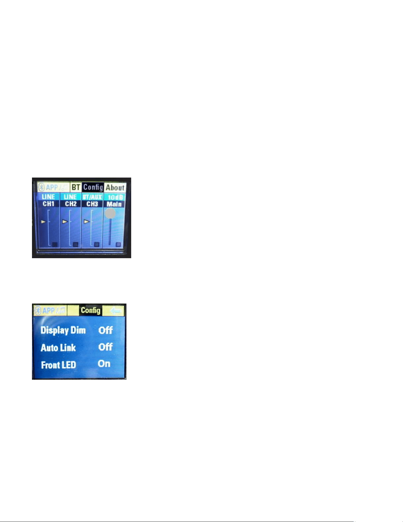
Level Indications on the LCD Display Screen (10)
The LCD screen for the DSP menu also displays a set of level indicator bars in
each segment of the display, channels 1, 2, 3 and the Main (Master) segment.
See Fig. A below, and compare to Fig. 1 a little bit further down.
Fig. A Level Indicator Bars
These indicator bars can be helpful in determining the relative level between
channels, and to see the overall signal level structure. Note that they do not
respond to quick, short transients, but are more of an averaging style of
indication.
They will not be accurate to try and determine when the system has reached it's
output limits, that would best be determined by turning the front baffle LED
indicator to "Limit" mode, as outlined in the Config menu section below, see Figs
53, 54, and 55 and their associated explanations. Please note the information
provided about when the LED indicator turns RED when the Limit indication
function is selected.
Disconnecting AC Power to the PVX™p 10
We recommend that the Power switch (3) be used to turn the unit off first, and
then the AC power cord can be removed, this minimizes stress to the power
amplifiers and the transducers from turn-off transients. The power switch has an
arc suppression capacitor to help during turn-off, and tends to make a clean
disconnect from the AC power, while the power cord IEC connector can make
intermittent contact before finally becoming fully disconnected, e.g., as when
wiggling the cord.
Loudspeaker System Specifications
15
DSP Menu
The DSP menu is accessed via the Push for DSP knob (9), and is displayed on
the LCD Screen for DSP Menu (10).
In this section, we will step through the DSP menu as it is displayed and as each
layer is accessed.
When the unit is first turned on, it displays the Peavey® logo, and then a yellow
bar across the bottom showing the progress of the loading into working memory
of the DSP code, and the model is displayed above the progress bar until it is
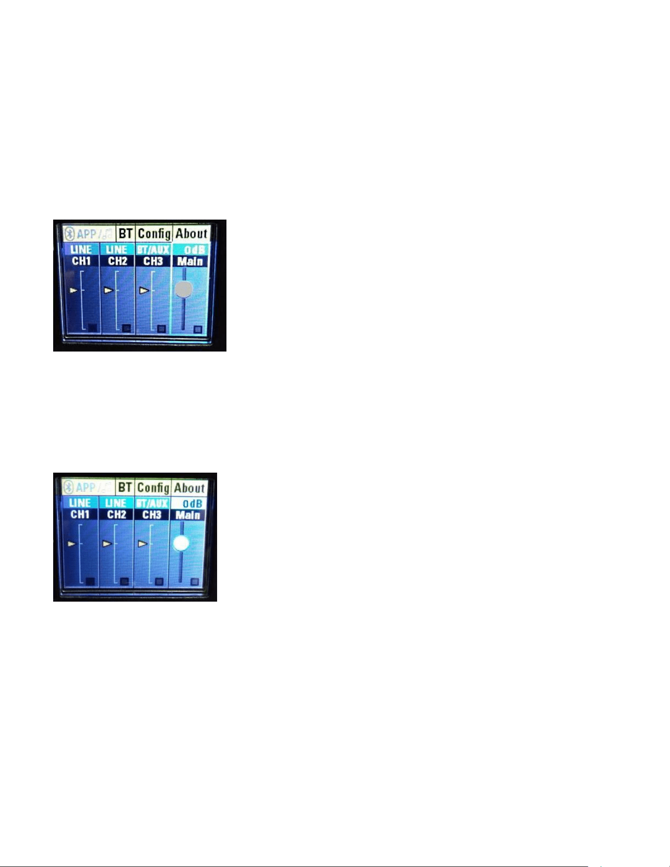
finished loading. Then you see the Main Start Screen.
Fig. 1 Main Start Screen
MAIN (MASTER) LEVEL ADJUST
If you turn the "Push for DSP" knob (9) CCW one notch, then the volume knob
will become highlighted, if you push in the "Push for DSP" knob in, then the "dB"
level indicator highlights, and turning the "Push for DSP" knob will change the
Master Gain level, see figure below.
Fig. 2 Main (Master) Channel Gain (Default)
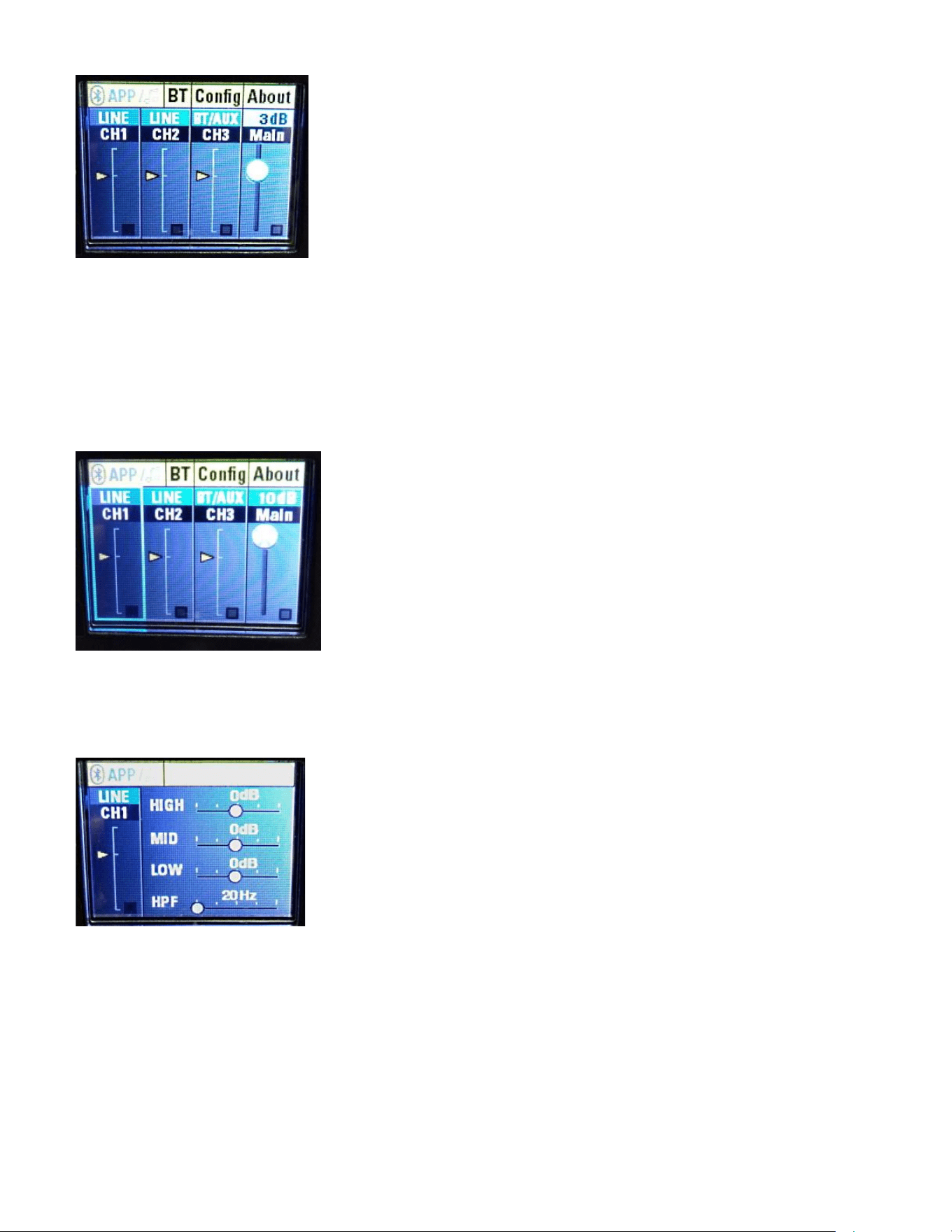
Here is an example of the gain being changed to +3 dB
Loudspeaker System Specifications
16
Fig. 3 Main (Master) Channel Gain +3 dB
The Main (Master) Channel gain is variable from +10 dB to -80 dB.
CHANNELS 1 THRU 3 ADJUSTMENTS
If from the Main Start Screen of Fig. 1, you click the "Push for DSP" knob CCW 4
times, then you end up highlighting the CH1 segment, see below:
Fig. 4 Main Screen - CH1
Then if you push in the "Push for DSP" knob in, you will get the menu for
Channel 1's controls. These consist of three bands of EQ, and an adjustable
high pass filter. See Fig. 5 below:
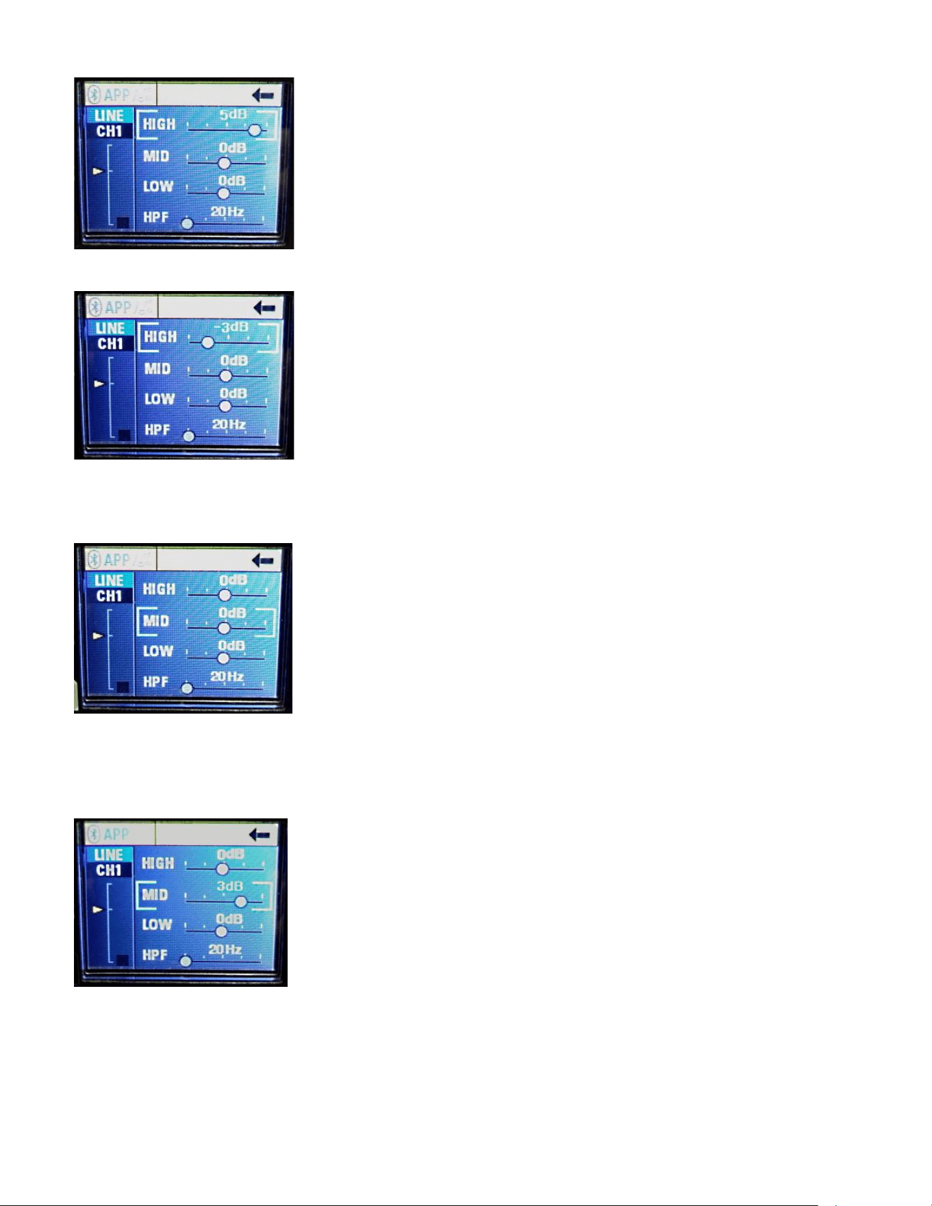
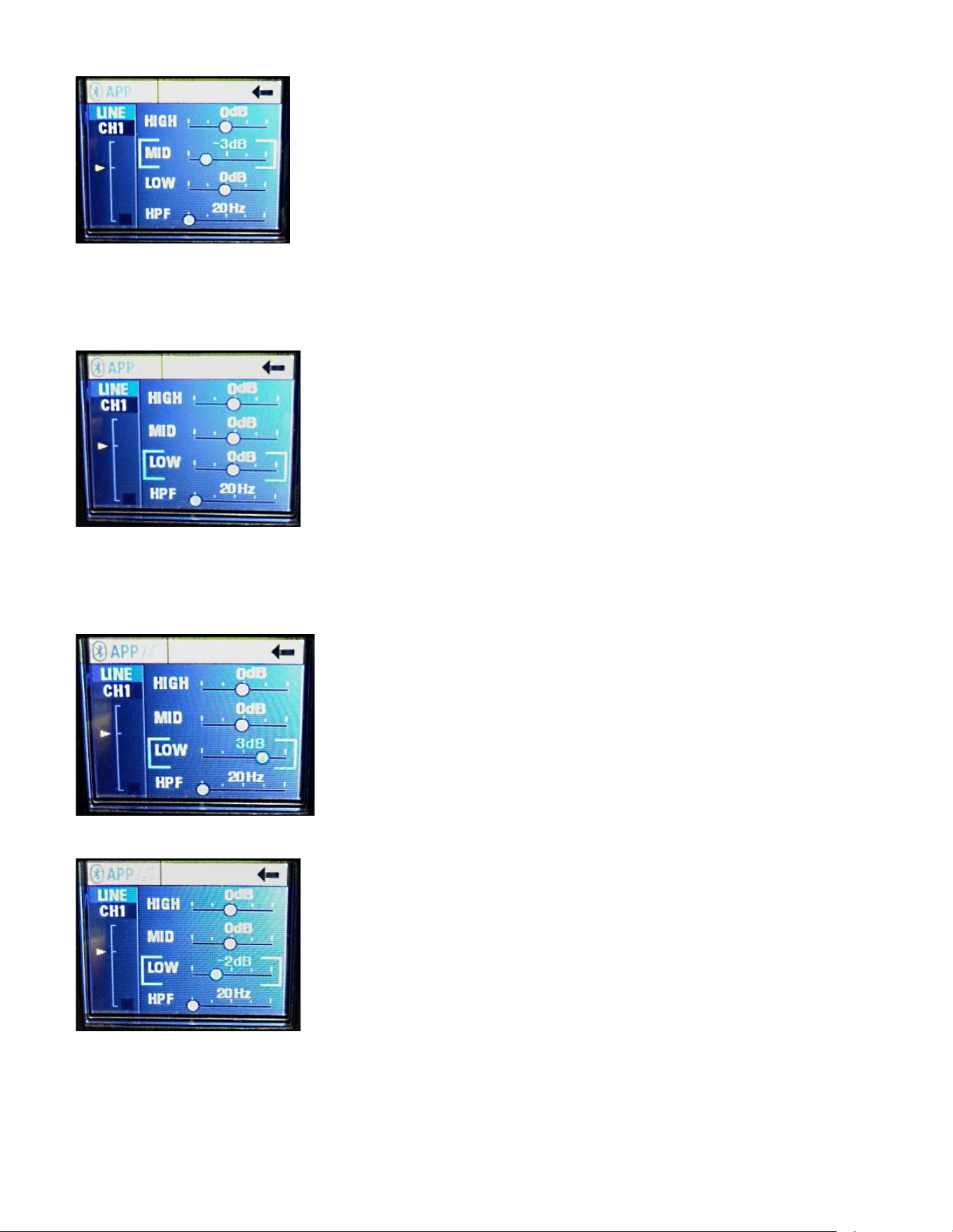
Fig. 5 CH1 Selections
Turn the "Push for DSP" knob one click CW, and the High EQ band is selected.
Push in the knob to activate the EQ slider. Now turning the knob CW increases
the HF boost above 8 kHz up to 6 dB, then turning it all the way CCW the high
frequencies are cut by 6 dB, in 1 dB increments.
See Fig. 6 and Fig. 7
Loudspeaker System Specifications
17
Fig. 6 CH1 High band EQ, +5 dB
Fig. 7 CH1 High band EQ, -3 dB
From Fig. 5, turn the "Push for DSP" knob two clicks CW, and the Mid EQ band
is selected.
Fig. 8 CH1 Mid band EQ
Push in the knob to activate the EQ slider. Now turning the knob CW increases
the Mid boost at 600 Hz by up to 6 dB, turning it all the way CCW cuts the Mid
frequencies by up to 6 dB, in 1 dB increments. See Fig. 9 and Fig. 10
Fig. 9 CH1 Mid band EQ, +3 dB
Loudspeaker System Specifications
18
Fig. 10 CH1 Mid band EQ, -3 dB
From Fig. 5, turn the "Push for DSP" knob three clicks CW, and the Low EQ
band is selected.
Fig. 11 CH1 Low band EQ
Push in the knob to activate the EQ slider. Now turning the knob CW increases
the Low boost at 100 Hz by up to 6 dB, turning it all the way CCW cuts the Low
frequencies by up to 6 dB, in 1 dB increments. See Fig. 12 and Fig. 13
Fig. 12 CH1 Low band EQ, +3 dB
Fig. 13 CH1 Low band EQ, -2 dB
Loudspeaker System Specifications
19
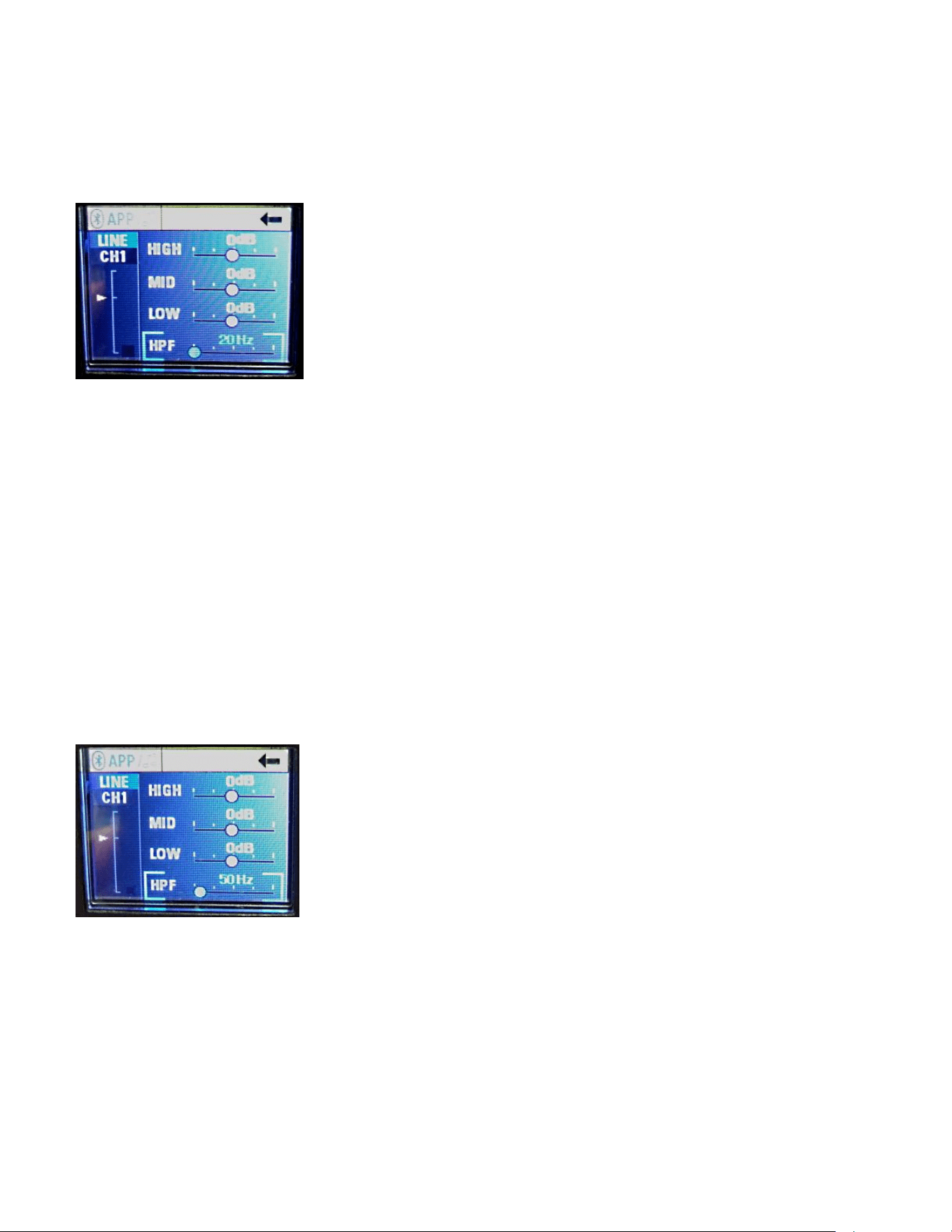
From Fig. 5, turn the "Push for DSP" knob four clicks CW, and the HPF Filter
band is selected. HPF stands for High Pass Filter, which rolls off low
frequencies. See Fig. 14.
Fig. 14 HPF Filter Band
The default filter frequency is 20 Hz, and the filter type is a 2nd order Bessel.
Normally, there is no need to change this setting, but if the speaker will be used
for speech only, or other limited bandwidth signal sources, or with a microphone
exposed to the wind, or excessively plosive talkers, etc. then raising the
frequency of this filter may be helpful in taming these undesired sounds.
Note that raising the frequency to a value above 20 Hz WILL start to roll-off the
lower frequencies, and limit how low a frequency the speaker system can
reproduce. Setting the filter very much higher than 140 Hz should not be
necessary except in extreme and unusual circumstances.
The range of frequencies it can be set to are from 20 Hz to 400 Hz.
Also note that the entire speaker system is protected by a 36 dB/oct. infra-sonic
filter, and this HPF Channel filter is added on top of that existing filtering.
An example of the HPF set to 50 Hz is shown below in Fig. 15
Fig. 15 HPF set to 50 Hz
Note that CH3, the set of Gain and EQ controls for the Bluetooth® signal source,
does not have this filter available, as most pre-recorded music or sources do not
have very much extreme low-frequency content or opportunity to generate
excessive plosives or mic noises, etc.
Loudspeaker System Specifications
20
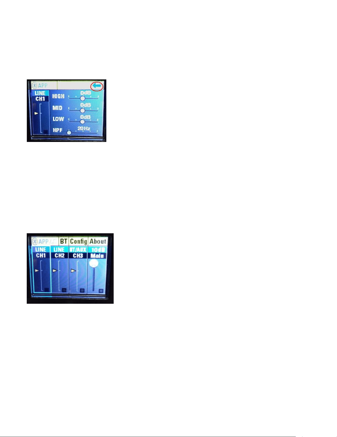
To exit the CH1 EQ and Filter settings, after making any changes to the EQ or
Filter, turn the "Push for DSP" knob until the arrow pointing to the left in the
upper right hand corner of the screen turns from black to light blue.
See Fig. 16, where the blue arrow is circled in red.
Fig. 16 Exit CH menu
Pushing in the "Push for DSP" knob will return you to the Main Screen - CH1,
Fig. 4
Fig. 4 Main Screen - CH1
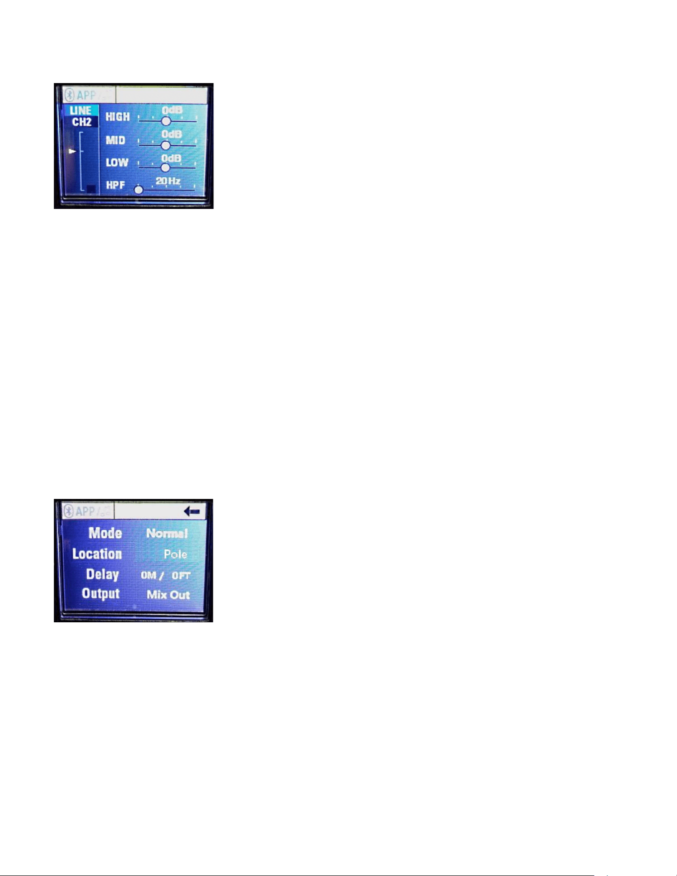
From here, you can use the "Push for DSP" knob and rotate it to arrive at any of
the channels desired, such as CH2, and active it's EQ and Filter menu as
outlined above for CH1. See Fig. 17.
Loudspeaker System Specifications
21
Fig. 17 CH2 Selections
Similarly, you can reach CH3, the adjustments for the Gain and EQ controls for
the Bluetooth® signal source, and push in the "Push for DSP" knob to access
these channel settings. As noted above, this channel does not have any HPF or
adjustments for same.
PARAMETERS MENU
From the Main Start Screen, Fig. 1, if you push in the "Push for DSP" knob
instead of rotating it, a menu screen comes up that allows for adjustment of the
following speaker system parameters:
MODE
LOCATION
DELAY
OUTPUT
See Fig. 18
Fig. 18 Parameters Menu
Mode selects the speaker system EQ Preset.
Location selects the physical location of the speaker with respect to physical
boundaries.
Delay selects how long the input signal is delayed before it is output as sound.
Output selects the mode of the Output jack, Mix or Thru
Turning the "Push for DSP" knob one click CW highlights the Mode parameter,
push in the "Push for DSP" knob, and the parameter is selected.
See Fig. 19
Loudspeaker System Specifications
22
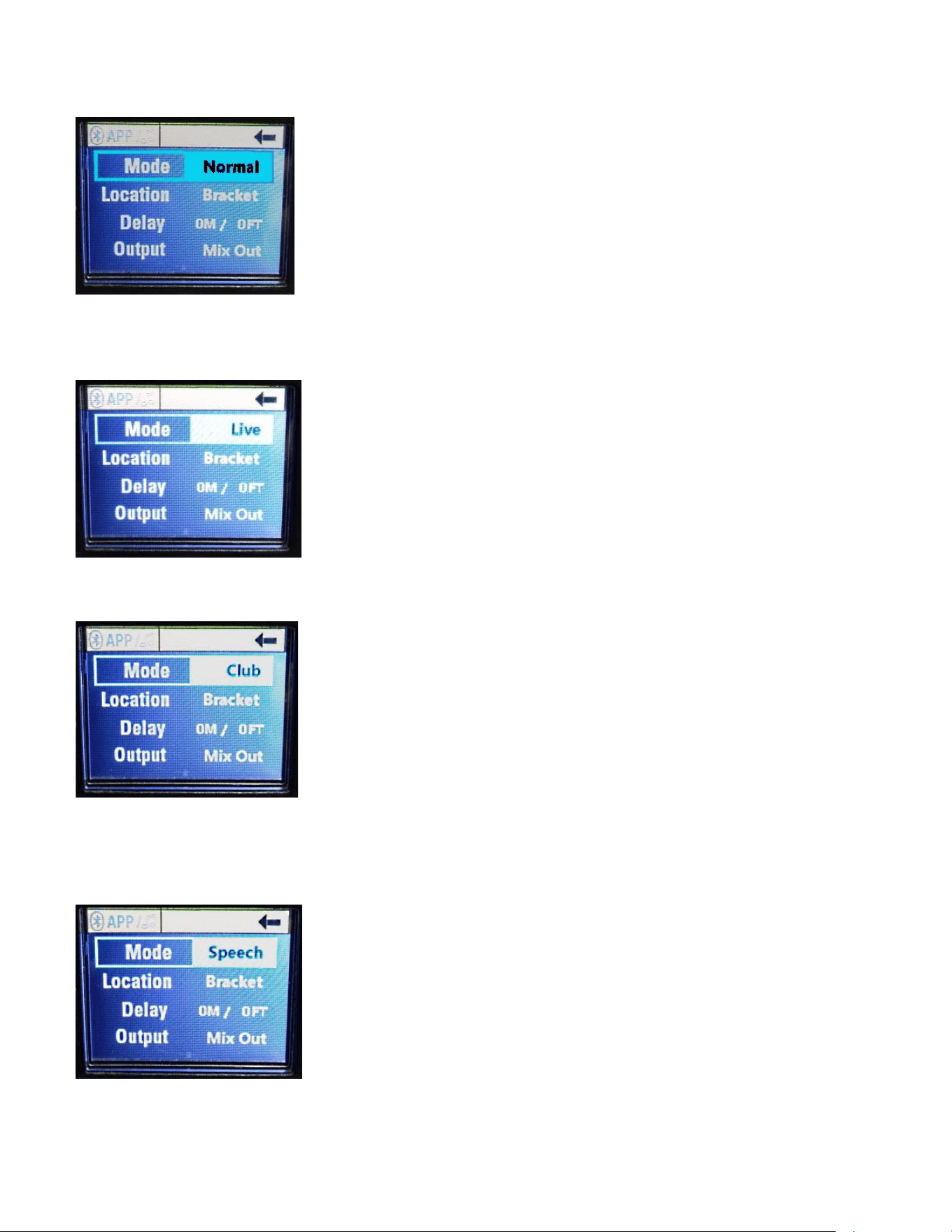
Fig. 19 Mode Parameter Selected
Turning the "Push for DSP" knob brings up the other Mode selections:
Live
Fig. 20 Live Mode Highlighted
Club
Fig. 21 Club Mode Highlighted
and
Speech
Fig. 22 Speech Mode Highlighted
Loudspeaker System Specifications
23
Once a given Mode has been highlighted, pressing the "Push for DSP" knob will
select that Mode, and the highlight will end.
The "Push for DSP" knob can now be rotated to the next parameter or to Exit.
To Exit, turn the "Push for DSP" knob until the arrow pointing to the left in the
upper right hand corner of the screen turns from black to light blue.
See Fig. 16, where the blue arrow is circled in red. Then push in the "Push for
DSP" knob once the Exit arrow has turned blue.
Normal Mode provides the flattest frequency response.
Live Mode provides a slight boost at the frequency extremes and some midband
EQ.
Club Mode provides more boosts at the frequency extremes, with the emphasis
on some extra bass, and with some upper midrange EQ.
Speech Mode rolls off the frequency extremes, and provides a boost in the
presence range for improved vocal intelligibility.
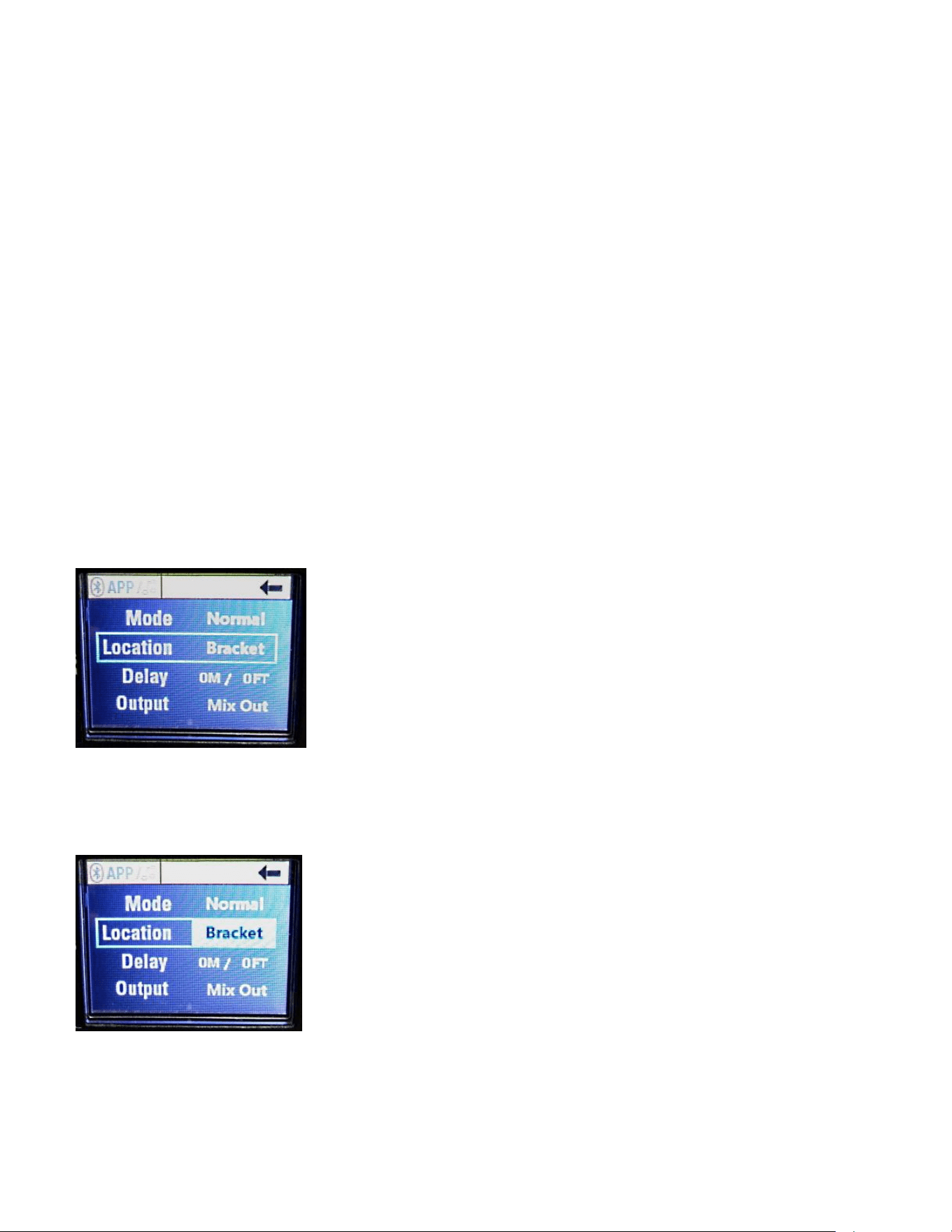
Location Parameter
The Location parameter can be accessed from the Parameter menu (Fig. 18) by
rotating the "Push for DSP" knob, and selecting the Location parameter, see Fig.
23
Fig. 23 Location Parameter Selection
Pushing in the "Push for DSP" knob when it is on this parameter will highlight
that parameter, see Fig. 24
Fig. 24 Bracket Location Selected
Loudspeaker System Specifications
24
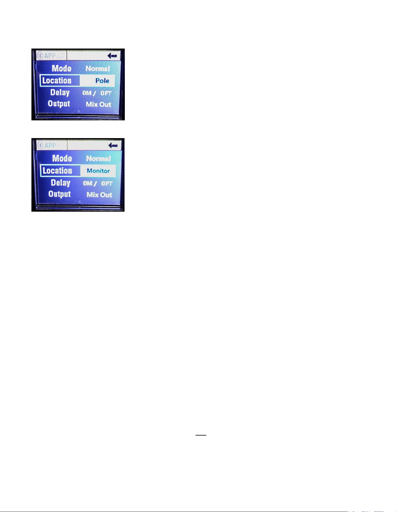
Fig. 25 Pole Location Selected
Fig. 26 Monitor Location Selected
The Pole location provides slight bass boost to compensate for the speaker
system being away from any boundaries such as a wall or corner. It assumes
that the speaker system is at least 6 feet or more off the ground on a pole or
stand.
The Bracket location is for nominal wall placement of the speaker system.
This location setting provides a nominally flat response in the bass under
anechoic conditions. This combined with the Normal mode Preset provides the
very flattest response the speaker is capable of.
The Monitor location setting corrects for the bass boost that floor placement
provides, by slightly reducing the overall bass level to compensate.
These three location settings along with the four Presets provide for 12 different
EQ profiles that are repeatable and precise. These coupled with the Channel
EQ (Low Mid and High band EQ) provide for literally thousands of repeatable
and precise EQ settings available to the end user.
CAUTION!
This speaker system has built-in EQ and frequency shaping to achieve a
basically flat frequency response, as well as Presets and EQ settings available
that can have significant amounts of bass boost beyond a nominally flat
response. It is strongly recommended that you not
ADD additional bass boost
EQ external to the speaker system, as this will pose a very real probability of
creating an overload situation, where the vocals or high frequencies are left
weak and muddied, and the apparent loudness of the speaker system will be
Loudspeaker System Specifications
25
curtailed due to this imbalance in bass EQ. Let the speaker system's built-in EQ
work FOR YOU, and do not attempt to try and make it behave as if it were a
Subwoofer equipped cabinet.
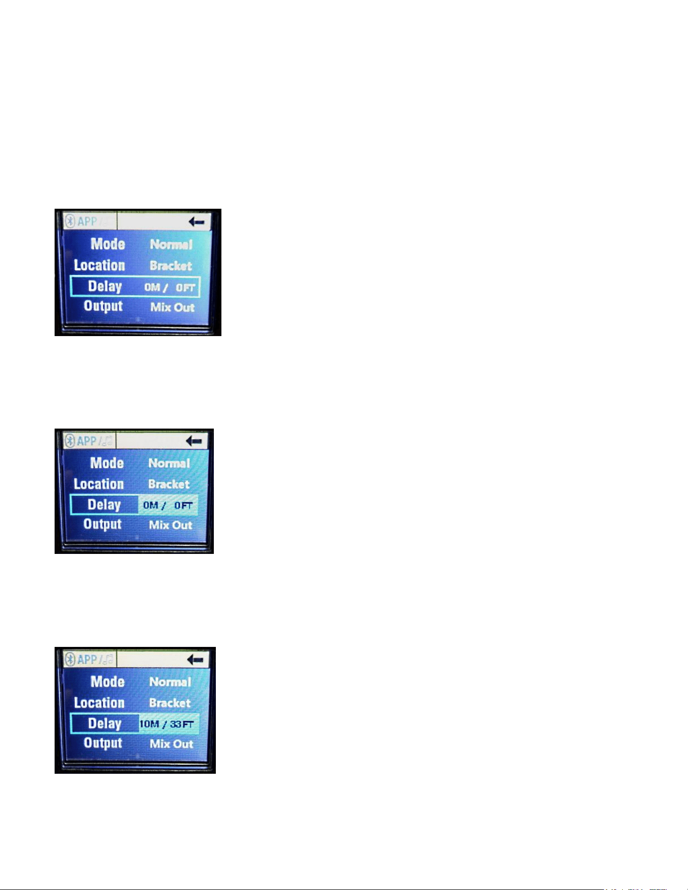
Delay Parameter
The Delay parameter can be accessed from the Parameter menu (Fig. 18) by
rotating the "Push for DSP" knob, and selecting the Delay parameter, see Fig. 27
Fig. 27 Delay Parameter
Note that these are NOT mis-spelled ON and OFF selections, they are zero
meters and zero feet.
Push in the "Push for DSP" knob to highlight this parameter, see Fig. 28
Fig. 28 Delay Parameter Selected
This can adjust the entire speaker systems signal delay to 33 feet or 10 meters,
in one meter increments. 10 meters/33 feet is approximately 29 ms, and 1
meter/3.28 feet is approximately 2.91 ms. See Fig 29
Fig. 29 Delay Parameter at Maximum
Loudspeaker System Specifications
26
This parameter would normally not be used for live sound on stage situations,
but rather, for when the speaker system is used as a side fill or for delay towers.
Should be set to 0 delay for almost all live sound situations.
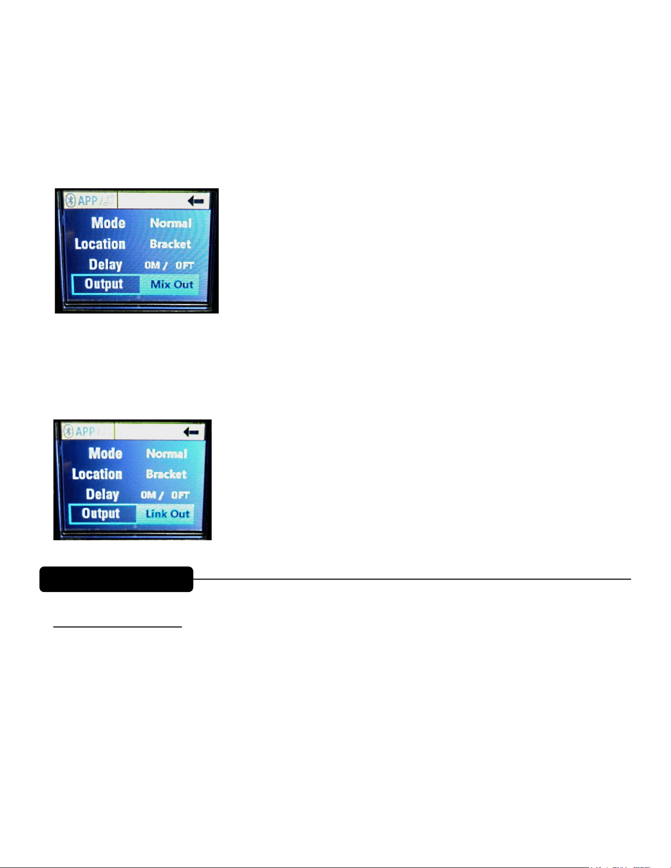
Output Parameter
The Output parameter selects either Mix Out or Link Out, see Fig. 30
Fig. 30 Output Parameter, Mix Out Selected
Mix Out sends the signal present at CH1, CH2 and the Bluetooth® CH3 all mixed
together to the Output jack.
Link Out sends just the signal present at the CH1 input to the Output jack, see
Fig. 31
Fig. 31 Output Parameter, Link Out Selected
Bluetooth® Controls
How to Turn OFF the blinking Bluetooth® LED (8) if you are not going to be
using Bluetooth®
From Fig. 1 the Main Start Screen, if you turn the "Push for DSP" knob (9) CW
one notch, then the BT menu header will become highlighted, see Fig. 32 below.
Pushing in the "Push for DSP" knob in selects the BT menu, see Fig 33 below.
Turning the "Push for DSP" knob CW two notches selects the Streaming
parameter, see Fig. 38 below.
Push in the "Push for DSP" knob to enter the Streaming menu, and turn the
"Push for DSP" knob one notch CW to select OFF, see Fig. 39 below.
Push in the "Push for DSP" knob to turn the Streaming OFF, and the Bluetooth®
LED (8) will turn OFF.
Loudspeaker System Specifications
26
This parameter would normally not be used for live sound on stage situations,
but rather, for when the speaker system is used as a side fill or for delay towers.
Should be set to 0 delay for almost all live sound situations.
Output Parameter
The Output parameter selects either Mix Out or Link Out, see Fig. 30
Fig. 30 Output Parameter, Mix Out Selected
Mix Out sends the signal present at CH1, CH2 and the Bluetooth® CH3 all mixed
together to the Output jack.
Link Out sends just the signal present at the CH1 input to the Output jack, see
Fig. 31
Fig. 31 Output Parameter, Link Out Selected
Bluetooth® Controls
How to Turn OFF the blinking Bluetooth® LED (8) if you are not going to be
using Bluetooth®
From Fig. 1 the Main Start Screen, if you turn the "Push for DSP" knob (9) CW
one notch, then the BT menu header will become highlighted, see Fig. 32 below.
Pushing in the "Push for DSP" knob in selects the BT menu, see Fig 33 below.
Turning the "Push for DSP" knob CW two notches selects the Streaming
parameter, see Fig. 38 below.
Push in the "Push for DSP" knob to enter the Streaming menu, and turn the
"Push for DSP" knob one notch CW to select OFF, see Fig. 39 below.
Push in the "Push for DSP" knob to turn the Streaming OFF, and the Bluetooth®
LED (8) will turn OFF.
BLUETOOTH® OPERATION
Mix Out is the combined post fader/EQ signal of Ch1, Ch2 and Bluetooth channels mixed together.
In this mode, the channel EQ/faders will aect the signal level at the output jack.
Link Out is the combined pre fader/EQ signal of Ch1, Ch2 and Bluetooth channels mixed together.
Loudspeaker System Specifications
27
Then, turn the "Push for DSP" knob two notches CCW to reach the blue Exit
arrow (See Fig. 16 for the Exit arrow circled in Red) and press the "Push for
DSP" knob in to return to the menu screen with the Bluetooth® menu highlighted
(Fig. 32), then rotate the "Push for DSP" knob CCW one notch to return to
the Main menu screen of Fig. 1
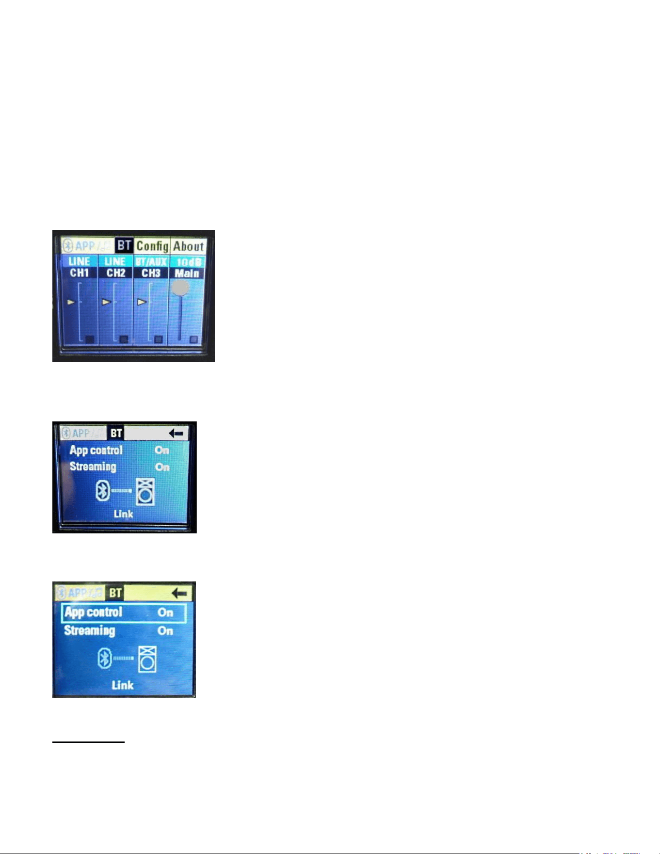
Bluetooth® Functions
From Fig. 1 the Main Start Screen, if you turn the "Push for DSP" knob (9) CW
one notch, then the BT menu header will become highlighted, see Fig. 32
Fig. 32 Bluetooth® Menu header Highlighted
Pushing in the "Push for DSP" knob in selects the BT menu, see Fig 33.
Fig. 33 Bluetooth® Menu
Turning the "Push for DSP" knob CW one notch selects the App Control
parameter, see Fig. 34.
Fig. 34 App Control selected
App control
There are three available settings; On, Off and Secondary.
Loudspeaker System Specifications
28
On" allows the speaker to be controlled with the PVX™p App (available
for the iPhone® only). See "Bluetooth® Connection Instructions" for how
to connect the speaker to a Bluetooth® device. It should also be set to
"On" when this is the primary speaker in the linked configuration, and app
control of the linked speakers is desired. Push in the "Push for DSP"
knob to select the App Control parameter. See Fig. 35
Fig. 35 App Control On highlighted
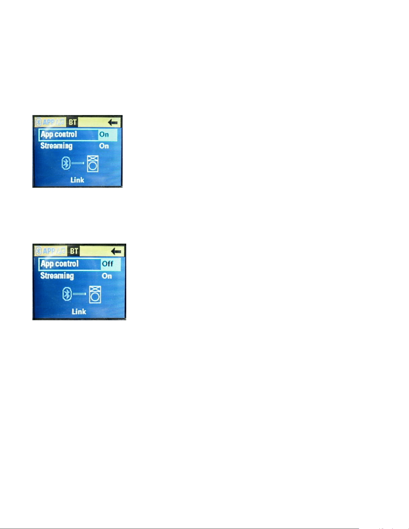
"Off" disconnects the speaker from App control and resets the internal
DSP gains to 0 dB on the Gain slider. Rotate the "Push for DSP" knob
CW to select the Off parameter, and then push it in. See Fig. 36
Fig. 36 App Control Off highlighted
The App Control is now Off, and the PVX™p speaker system is operating
without any outside control by a Bluetooth® device. Certain Bluetooth®
operations can still be performed using the PVX™p speaker system's controls.
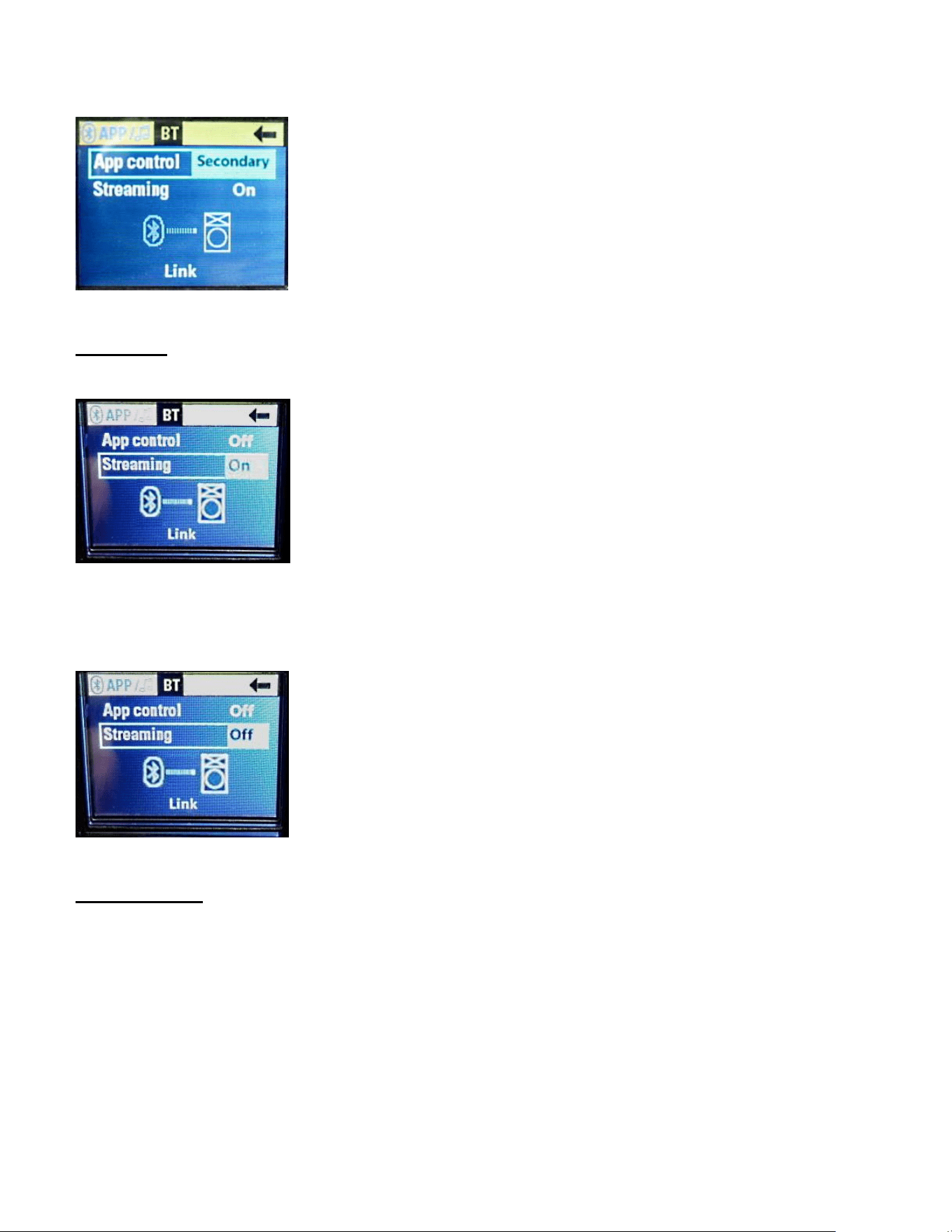
"Secondary" allows the speaker to be controlled by the app when two
speakers are linked. The secondary speaker will be the Right speaker in
this setup. See complete instructions in the "Linking Speakers" section.
Rotate the "Push for DSP" knob CW to select the Secondary parameter,
and then push it in. See Fig. 37
Loudspeaker System Specifications
29
Fig. 37 App Control Secondary parameter highlighted
Streaming
There are two available settings, "On" or "Off". It should be set to "On" to enable
the speaker to receive audio from a handheld Bluetooth® device.
Fig. 38 Streaming parameter On
It can be turned off to prevent the speaker from receiving audio from an
unwanted source. See Fig. 39
Fig. 39 Streaming parameter Off
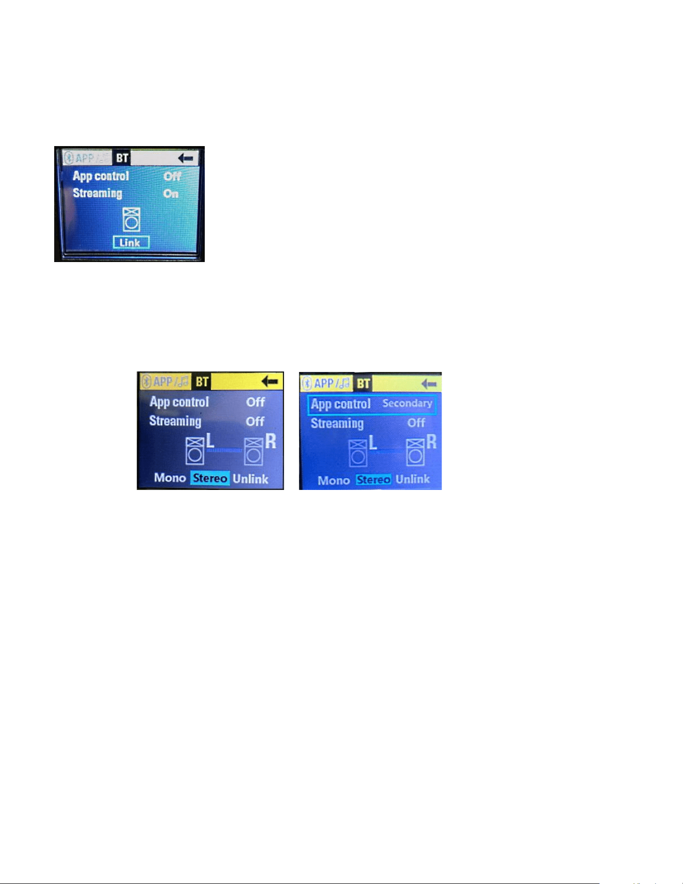
Link Speakers
The PVX™p speakers can be linked together to create a stereo system or a
mono system with two speakers. Additionally, it can be controlled with the App.
To setup a simple stereo system, no Bluetooth® streaming.
On the primary PVX™p speaker, App Control and Streaming
should both be turned off.
On the secondary PVX™p speaker, App Control should be set to
Secondary and Streaming should be off.
Loudspeaker System Specifications
30
On the primary speaker, use the "push for DSP" knob to navigate
to the "LINK", push in the knob to activate the linking action. See
Fig. 40.
Fig. 40 Link parameter selected
Once they connect, the primary speaker will be the Left channel
and the secondary speaker will be the Right channel. The
Left/Right signals can be swapped within the app.
Primary Secondary
Fig. 41 Fig. 42
In order for this to work well, the Secondary speaker must be in Bluetooth®
range of the Primary speaker, and in order to have a good clean connection, it
would be wise to make sure that the Secondary speaker is well within the range
of the Primary, and that there are no metal walls, or other RF shielding structures
between the two speakers.
To add Bluetooth® streaming:
On the primary (Left) PVX™p speaker, turn Streaming from "Off" to
"On".
On your device, make a Bluetooth® connection to the PVX™p
speaker.
The volume of the Bluetooth® signal will be controlled by the CH3
Level controls on each PVX™p speaker (independently).
To add App control:
On the primary PVX™p speaker, turn App control from "Off to On".
The App should connect to and control both linked PVX™p
speakers.
Loudspeaker System Specifications
31
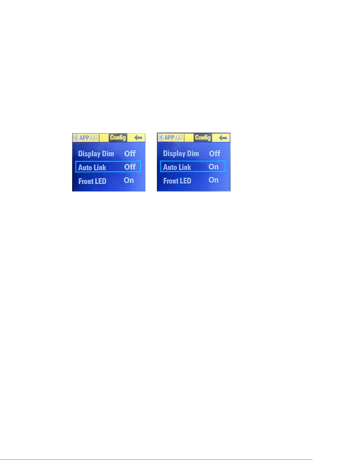
Auto Link
If it is desired that the PVX™p speakers link all of the time as part of a
permanent setup, the two speakers can be set to automatically link every time
they are turned on.
On each PVX™p speaker (Primary and Secondary), navigate to
the "Config" screen. See the Config Menu section below this
section.
Change the "Auto Link" setting from "Off" to "On".
Fig. 43 Fig. 44
To stop the Auto Link feature, simply turn it back to "Off" on each
speaker.
Bluetooth Connection Instructions:
Streaming Audio
On the PVX™p speaker, navigate to the Bluetooth® screen (BT
header and subsequent menu, Fig. 33, 34)
Set Streaming to "On"
The PVX™p speaker's Bluetooth® LED (8) will start blinking
On your Bluetooth® device, navigate to Bluetooth® settings
Select PVXp speaker
The Bluetooth® device should change from "Not Connected" to
"Connected"
Once connected, the PVX™p speaker Bluetooth LED (8) will light
solid.
App Control
In the Bluetooth® App Control menu, change the PVX™p
speaker's "App Control" from "Off" to "On".
Open the App on your Bluetooth® device. The speaker should
connect automatically.
The PVX™p speaker Bluetooth® LED (8) will light solid.
The connected speaker will be listed at the top of the App in the
Device list.
32
Loudspeaker System Specifications
Bluetooth® Range Information
This is a Class 2 Bluetooth® device, and as such is designed to have a typical
maximum range of approximately 10m. However, any intervening materials,
such as walls, shelves, screens, people, or most anything made of a substantial
amount of metal, can reduce and affect that range.
CONFIG MENU
From Fig. 1 the Main Start Screen, if you turn the "Push for DSP" knob (9) CW
two notches , then the Config menu header will become highlighted, see Fig. 45
Fig. 45 Config Menu Header
Pushing in the "Push for DSP" knob in will then bring up the Config menus, see
Fig. 46
Fig. 46 Config Menu Selections
The selection choices are:
Display Dim
Auto Link
Front LED
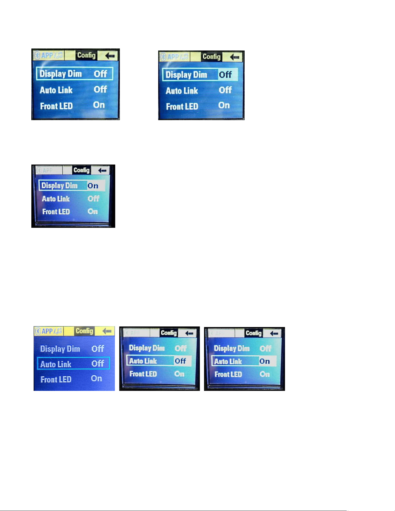
If you turn the "Push for DSP" knob (9) CW one notch, the Display Dim choice
will be highlighted, see Fig. 47.
Loudspeaker System Specifications
33
Fig. 47 Display Dim highlighted Fig. 47A Display Dim Selected
Push in the "Push for DSP" knob in to select the Display Dim choice.
You can now change the Display to Dim, and the selection will show that the
function is "On", see Fig. 48.
Fig. 48 Display Dim turned On
This will reduce the brightness of the display, so that when the speaker system is
used as a floor monitor, the LCD screen is not so bright towards the audience, or
if it needs to be dimmed for on stage use. The screen will dim once the
navigation knob is not moved for 10 seconds.
AutoLink
Auto Link allows two speakers in range of each other to automatically link to form
a stereo or dual mono system.
Fig. 49 Fig. 50 Fig. 51
See Bluetooth® Controls and the Auto Link section for more details.
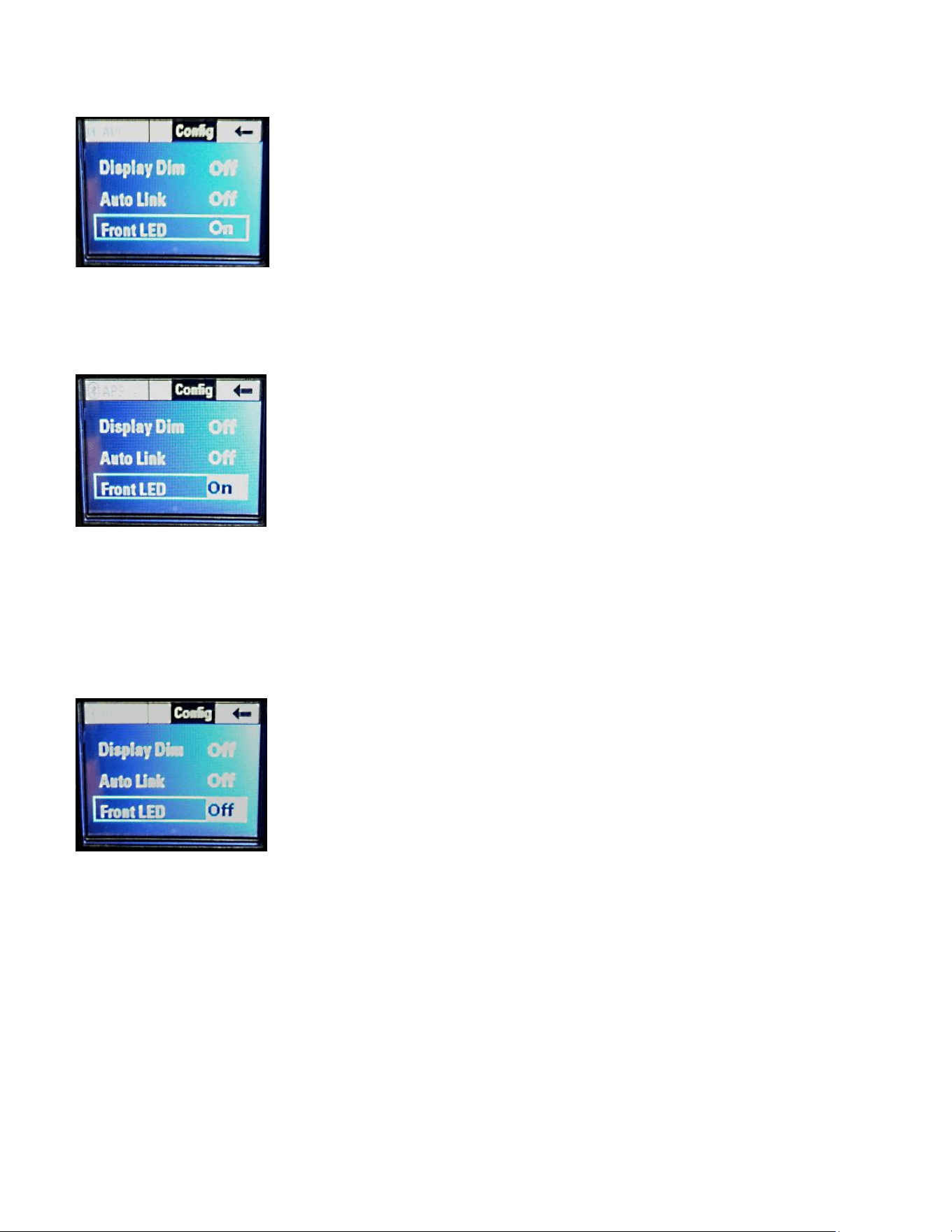
Front LED
From the Config Menu Selection screen (Fig. 46), if you turn the "Push for DSP"
knob (9) CW three notches, the Front LED choice will be highlighted, see Fig. 52.
Loudspeaker System Specifications
34
Fig. 52 Front LED Selection Highlighted
Pushing in the "Push for DSP" knob will select the Front LED parameter, see Fig.
53
Fig. 53 Front LED Selected
The Front LED is mounted on the front baffle behind the grille, and the LED
lights up Blue to show power has been supplied to the speaker system.
Rotating the "Push for DSP" knob will then change that parameter from On to
Off, see Fig. 54
Fig. 54 Front LED turned Off
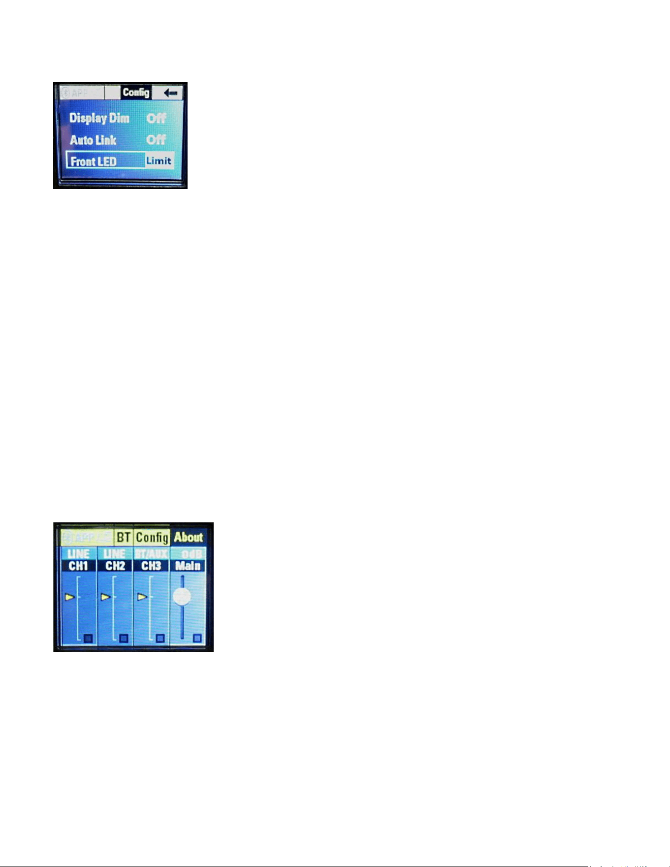
Turning the "Push for DSP" knob one more notch will chose the Limit function of
the Front LED. See Fig. 55
Loudspeaker System Specifications
35
Fig. 55 Front LED parameter set to Limit
Push in the "Push for DSP" knob to select the Limit parameter for the Front LED,
and to exit the Config Menu Selection screen, rotate the "Push for DSP" knob till
the arrow in the upper right hand corner turns blue, then press the "Push for
DSP" knob again to return to the Main Menu screen.
About the Limit Function of the PVX™p 10 Bluetooth® Speaker System
Choosing the Limit parameter allows the Front LED mounted on the baffle
behind the grille to flash RED when the sophisticated DSP based compression
and limiting system engages.
Note that this LED indication when the Limit parameter is selected does NOT
indicate amplifier clipping or system distress, it is OK for it to turn RED on a
regular but intermittent basis, as it just confirms that the compression and limiting
system is doing it's job providing as much clean and unclipped output as
possible. However, in the event that the LED is lighting up RED more often than
not, it would be wise to turn down the drive level, so that excess compression
does not occur to the sound.
ABOUT Header
From the Main Start Screen (Fig. 1), you turn the "Push for DSP" knob three
notch's CW, and the About header will be highlighted. See Fig. 56
Fig. 56 About header highlighted
Press in the "Push for DSP" knob, and the About menu will be selected, see Fig.
57
Loudspeaker System Specifications
36
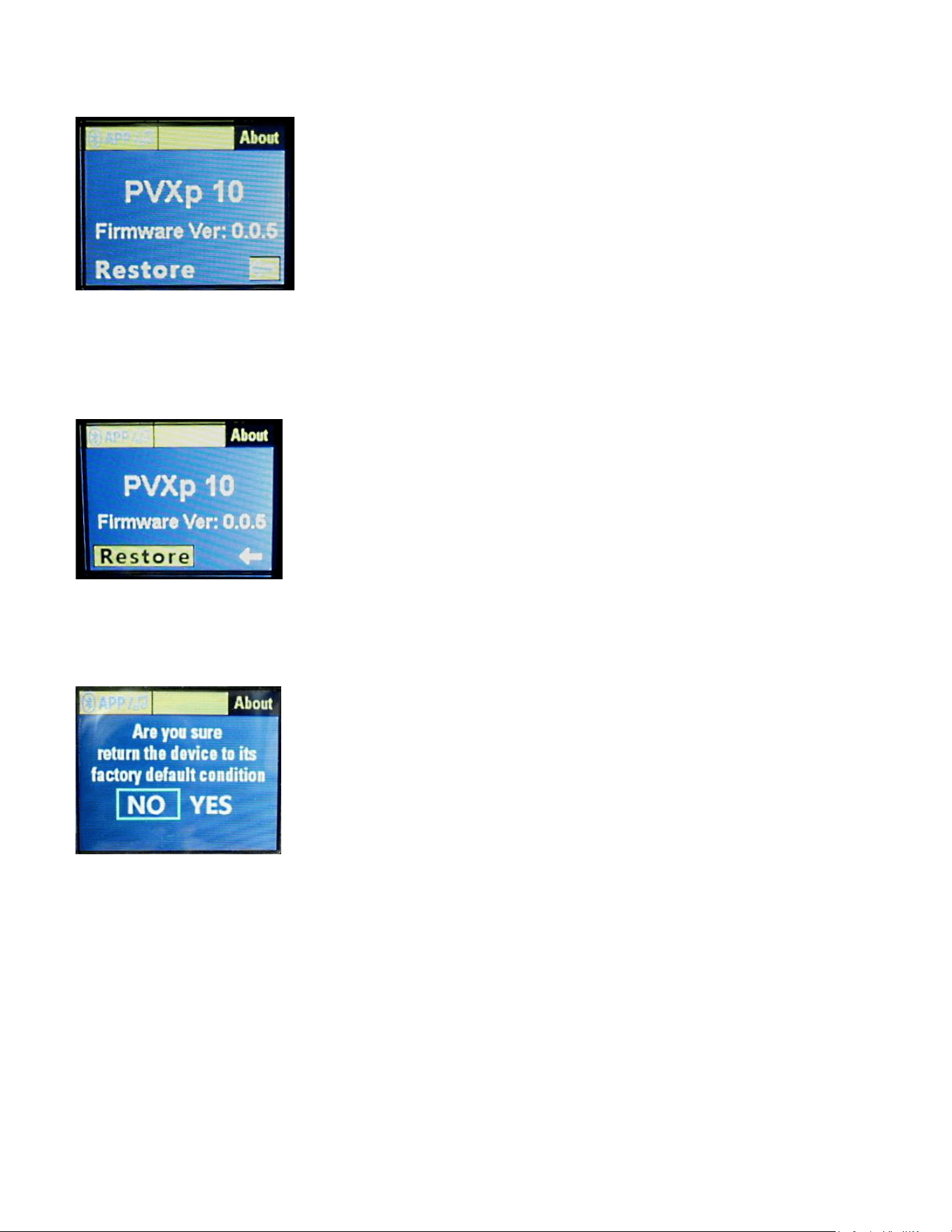
Fig. 57 About Menu
This displays the Model number of the PVXp, the firmware version, and the
Restore function. Turn the "Push for DSP" knob, and the Restore function will
be highlighted, see Fig. 58
Fig. 58 Restore Function Selected
Pressing in the "Push for DSP" knob will bring up the menu choice for the
Restore function, see Fig. 59.
Fig. 59 Restore Function Menu
Turn the "Push for DSP" knob, and it will change the menu selection from NO to
YES. See Fig. 60.

Loudspeaker System Specifications
37
Fig. 60
If you push in the "Push for DSP" knob now, the unit will restore to Factory
Defaults, and any custom set-up will be lost and have to be re-entered.
In order to assure proper operation, we recommend that the speaker
system be turned OFF, and turned back on again before using it or re-
loading any previously desired settings.
All previously loaded gain settings, Presets, Channel EQ choices, filter settings,
etc., will need to be re-loaded into the speaker system after a Factory Reset
event.
Normally, each time a change is made to the speaker system, whether it is the
Preset used, or the Location, or the Bluetooth® system, it will be saved, and on
powering the speaker system back ON, those settings will automatically come
back up. Using the Restore function can be helpful if someone has altered the
settings such that the speaker system will not function normally, or the files have
become corrupted due to a power spike, a brown-out, etc.
TROUBLESHOOTING
No Output at All
First, make sure the unit has AC power and is turned ON. Make sure the LED
on the power amp module is illuminated.
If not, make certain the ON/OFF switch (3) is in the ON position and check the
IEC power cord connection (2) by ensuring it is fully engaged and seated. Make
certain the AC line cord is plugged into a working AC outlet.
Finally, check the fuse (1). (See the Rear Panel: Fuse section, for safety
instructions.)
Once assured your unit is getting AC power, check that the PVX™p 10
Bluetooth® is getting a signal. Temporarily disconnect the cable running to its
inputs and connect it to some other device capable of reproducing the signal
(i.e., a power amp and speaker). If this produces a signal, make sure that all
Level controls being used have been turned up to a satisfactory level (one-third
to halfway).
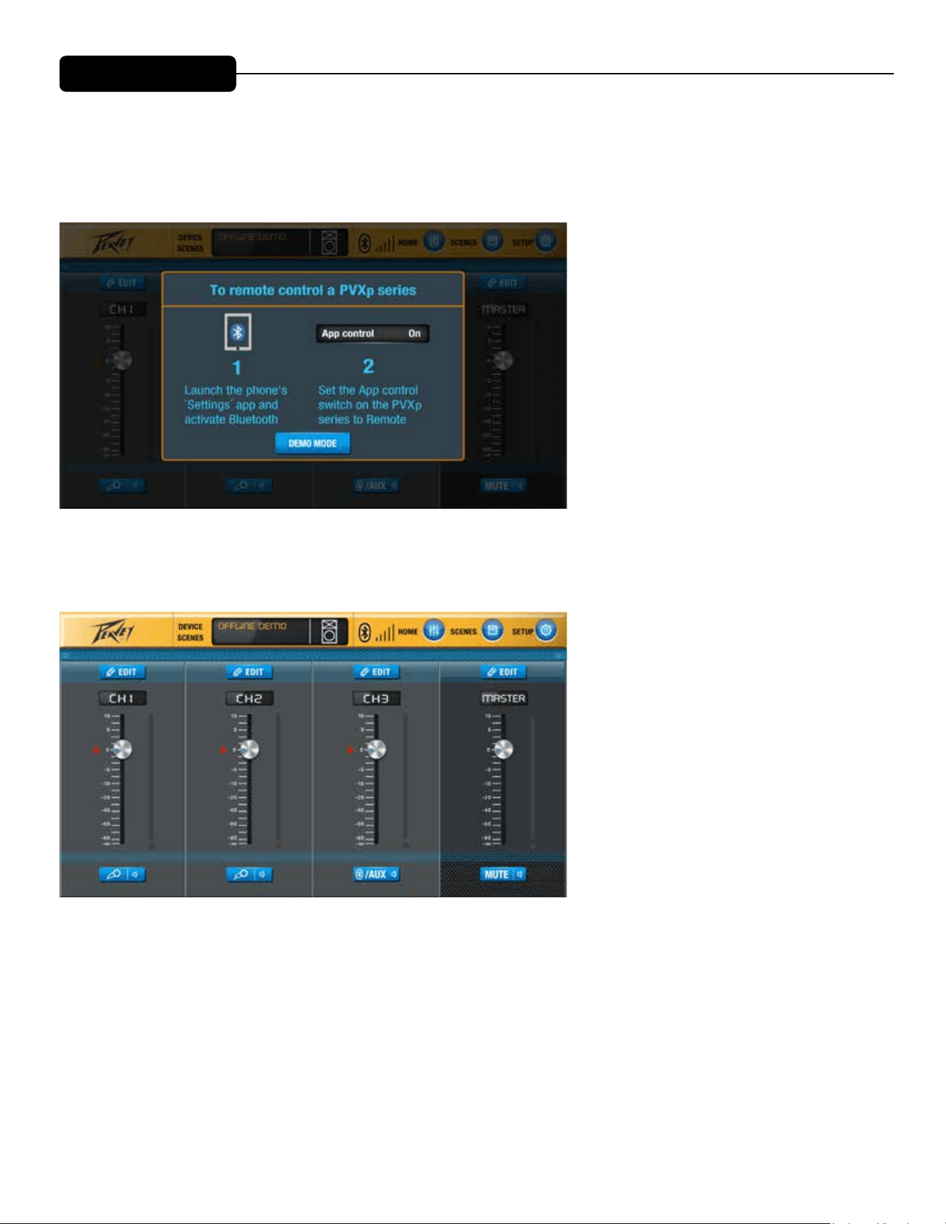
IOS APP FEATURES
e PVXp Bluetooth speakers can be controlled remotely via the PVXp Application on any iOS device. Applica-
tion is available for download on the Apple App Store.
e app controls are listed below. See also page 27 and page 32 of this manual.
Upon opening the application, the above screen will be displayed, prompting connection to the PVXp system.
e home screen display contains a level control for all three channels and a blue edit button above each chan-
nel for access to EQ adjustments at the channel level, as well as individual channel mutes. e Master level will
always be displayed on the right side for easy access.
*Note- Red arrows indicate the loca-
tion of the physical gain knobs on the
back of the speaker.
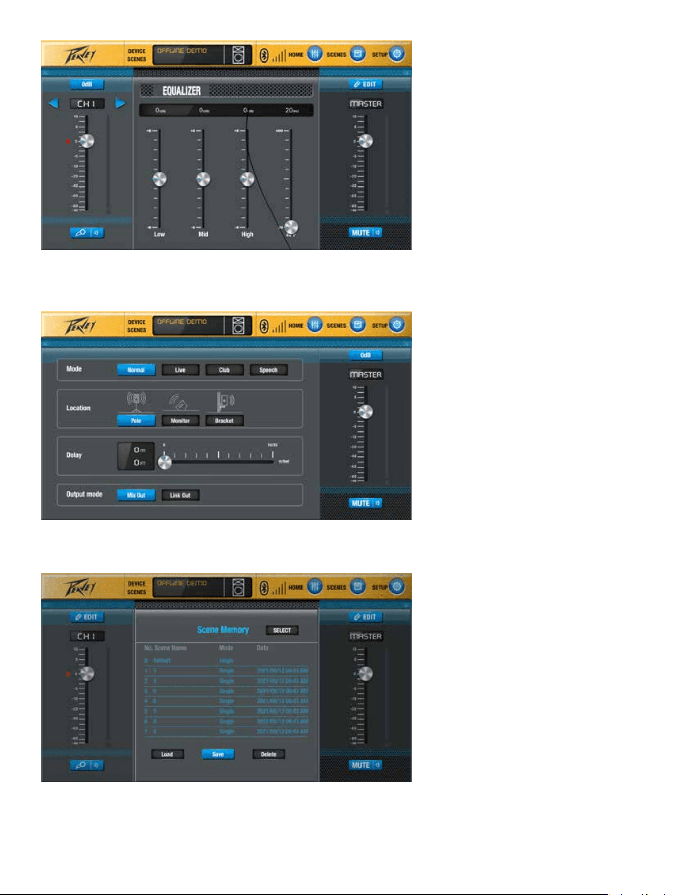
Pressing the blue Edit button will allow access to the Channel-level EQ controls. See also pg 21
e blue “SETUP” button allows access to the following functions: Mode, Location, Delay, and Output Mode.
e blue “Scenes” button will allow user easy access to save and load settings for specic applications.
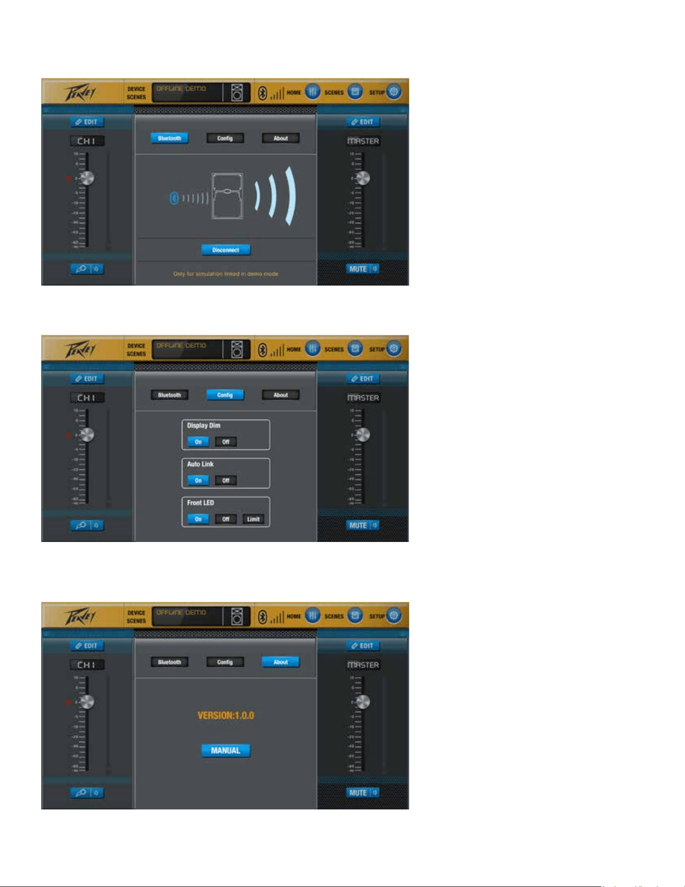
Additional features of the app are shown in following screens.
Connect and disconnect speaker via Bluetooth.
Control Display, Allow Auto Linking, and Allow LED display to signal Bluetooth connection.
Soware information

Loudspeaker System Specifications
37
Fig. 60
If you push in the "Push for DSP" knob now, the unit will restore to Factory
Defaults, and any custom set-up will be lost and have to be re-entered.
In order to assure proper operation, we recommend that the speaker
system be turned OFF, and turned back on again before using it or re-
loading any previously desired settings.
All previously loaded gain settings, Presets, Channel EQ choices, filter settings,
etc., will need to be re-loaded into the speaker system after a Factory Reset
event.
Normally, each time a change is made to the speaker system, whether it is the
Preset used, or the Location, or the Bluetooth® system, it will be saved, and on
powering the speaker system back ON, those settings will automatically come
back up. Using the Restore function can be helpful if someone has altered the
settings such that the speaker system will not function normally, or the files have
become corrupted due to a power spike, a brown-out, etc.
TROUBLESHOOTING
No Output at All
First, make sure the unit has AC power and is turned ON. Make sure the LED
on the power amp module is illuminated.
If not, make certain the ON/OFF switch (3) is in the ON position and check the
IEC power cord connection (2) by ensuring it is fully engaged and seated. Make
certain the AC line cord is plugged into a working AC outlet.
Finally, check the fuse (1). (See the Rear Panel: Fuse section, for safety
instructions.)
Once assured your unit is getting AC power, check that the PVX™p 10
Bluetooth® is getting a signal. Temporarily disconnect the cable running to its
inputs and connect it to some other device capable of reproducing the signal
(i.e., a power amp and speaker). If this produces a signal, make sure that all
Level controls being used have been turned up to a satisfactory level (one-third
to halfway).
Loudspeaker System Specifications
38
If the PVX™p 10 Bluetooth® has been subjected to direct sunlight or excessive
heat, the built-in thermal protection may have been triggered. If so, turn off the
PVX™p 10 Bluetooth® and let it cool for a sufficient amount of time.
Try doing a system Restore, as described above in the DSP operating section,
this will return the unit to it's Factory Defaults, and reset all the controls to a
nominal setting, allowing the gain and frequency response to return to "normal".
If there is still no output, contact your authorized Peavey dealer or the Peavey
International Service Center.
Hum or Buzz
If the PVX™p 10 Bluetooth® is producing a hum or buzz, this can be AC outlet
related. Try plugging the PVX™p 10 Bluetooth® into a different AC outlet.
Sometimes, if a different circuit (breaker) is used for the mixer and for the
PVX™p 10 Bluetooth®, it can cause hum problems. Unless it is not practical, it
is best to use the same wall outlet (breaker) to supply power to both the mixer
and the powered speaker.
Ensure that shielded cables have been used to route the signal to the PVX™p
10’s input. If speaker cables with 1/4" plugs are used as input cables instead of
shielded cables, they will be prone to hum or buzz.
Hum may be ground loop related. It may be helpful to lift the shield ground (Pin
#1) on a balanced cable at the PVX™p 10 Bluetooth® end. Check any input
changes carefully by first turning down the Level control, before plugging and
unplugging cables, or lifting the shield ground at the speaker end.
Check to make sure light dimmers are not on the same circuit as the PVX™p 10
Bluetooth®, the mixer or any source devices. If light dimmers are used, then it
may be necessary to turn them full ON or full OFF to eliminate or reduce hum.
This is a typical AC wiring/light dimmer interference problem, not a design flaw of
the PVX™p 10 Bluetooth®.
The third wire (ground plug) on the AC plug should NEVER be removed or
broken off, as this is a potential safety hazard.
Distorted or Fuzzy Sound
First, ensure the mixer (signal source) is not clipping or being overdriven. Make
sure the Level (6) control on the PVX™p 10 Bluetooth® has not been set too
low.
Make sure that the MIC/LINE Switch (6), is not in the mic position when driving
the system with a line level signal. The analog input circuitry and the DSP
system will overload and cause severe distortion that can not be removed by
turning down the Level control !
TROUBLESHOOTING

Loudspeaker System Specifications
38
If the PVX™p 10 Bluetooth® has been subjected to direct sunlight or excessive
heat, the built-in thermal protection may have been triggered. If so, turn off the
PVX™p 10 Bluetooth® and let it cool for a sufficient amount of time.
Try doing a system Restore, as described above in the DSP operating section,
this will return the unit to it's Factory Defaults, and reset all the controls to a
nominal setting, allowing the gain and frequency response to return to "normal".
If there is still no output, contact your authorized Peavey dealer or the Peavey
International Service Center.
Hum or Buzz
If the PVX™p 10 Bluetooth® is producing a hum or buzz, this can be AC outlet
related. Try plugging the PVX™p 10 Bluetooth® into a different AC outlet.
Sometimes, if a different circuit (breaker) is used for the mixer and for the
PVX™p 10 Bluetooth®, it can cause hum problems. Unless it is not practical, it
is best to use the same wall outlet (breaker) to supply power to both the mixer
and the powered speaker.
Ensure that shielded cables have been used to route the signal to the PVX™p
10’s input. If speaker cables with 1/4" plugs are used as input cables instead of
shielded cables, they will be prone to hum or buzz.
Hum may be ground loop related. It may be helpful to lift the shield ground (Pin
#1) on a balanced cable at the PVX™p 10 Bluetooth® end. Check any input
changes carefully by first turning down the Level control, before plugging and
unplugging cables, or lifting the shield ground at the speaker end.
Check to make sure light dimmers are not on the same circuit as the PVX™p 10
Bluetooth®, the mixer or any source devices. If light dimmers are used, then it
may be necessary to turn them full ON or full OFF to eliminate or reduce hum.
This is a typical AC wiring/light dimmer interference problem, not a design flaw of
the PVX™p 10 Bluetooth®.
The third wire (ground plug) on the AC plug should NEVER be removed or
broken off, as this is a potential safety hazard.
Distorted or Fuzzy Sound
First, ensure the mixer (signal source) is not clipping or being overdriven. Make
sure the Level (6) control on the PVX™p 10 Bluetooth® has not been set too
low.
Make sure that the MIC/LINE Switch (6), is not in the mic position when driving
the system with a line level signal. The analog input circuitry and the DSP
system will overload and cause severe distortion that can not be removed by
turning down the Level control !
Loudspeaker System Specifications
39
Check that the input plug is fully seated in the input jack on the rear panel of the
PVX™p 10 Bluetooth®.
Ensure that a power amp has not been plugged into the input jack of the PVX™p
10 Bluetooth®.
If an extension cord is being used to provide the AC power to the unit, insure that
it is of sufficient current capacity and that it is not also being used to supply
power to any other device.
The PVX™p 10 Bluetooth® has built-in EQ to extend and smooth the natural
response of the speakers in the system. If excessive additional bass boost or
HF boost have been added externally to the PVX™p 10 Bluetooth®, it could
cause premature overload at high SPL. Reduce the amount of any external
(mixer, rack) EQ and see if that clears up the distortion.
Finally, realize that even though the PVX™p 10 Bluetooth® is a powerful and
high output unit, it does ultimately have limits, and it may need additional
powered units (or a subwoofer) to provide enough sound output or coverage. In
this case, try turning the mixer levels down a little to see if that clears things up.
If, after checking all the things listed to check and anything else you can think of
to check safely, and the system still exhibits problems, carefully note all
conditions and check with your Peavey dealer for advice.
Care and Maintenance
Your PVX™p 10 Bluetooth® is a sturdy and durable product and will provide
years of reliable use if properly cared for. Use common sense and read the
safety warnings to avoid hazardous operating conditions.
The unit must be disconnected from the AC power source before any work is
done on it. Refer all servicing to qualified service personnel.
Sunlight/Heat
Avoid prolonged exposure to direct sunlight, as this may cause the unit to
overheat and thermally shut off.
Excessively hot operating conditions can also cause a thermal shutdown.
Do not store in extremely hot or cold conditions or extremely high humidity.
Always allow unit to come to room temperature before use.
Cleaning
Never clean the PVX™p 10 Bluetooth® while plugged in or turned ON! When the
unit has been fully disconnected from AC power sources, use a dry cloth to
remove soil or other dirt. Never use strong solvents on the PVX™p 10
Bluetooth®, as they could damage the cabinet. Do not allow ANY fluids to drip
inside the PVX™p 10 Bluetooth®.

40
Loudspeaker System Specifications
Touchup
For an overall finish enhancement and protective coating, use gloves to apply a
plastic finish protector, such as Armor-All® protectant or a similar product, to the
surface of the plastic cabinet only. Note that the cabinet will be slippery after
these treatments; rub them down firmly with a dry, lint-free cloth to minimize this.
Check for Secure Hardware
After the first few months of use and periodically thereafter, check the hardware
of the PVX™p 10 Bluetooth® for tightness, including the rear panel screws and
the screws that hold the baffle and rear cabinet together.
The unit is subject to a great deal of vibration, and this could cause them to
loosen with use.
Architectural and Engineering Specifications
The powered loudspeaker system shall have a frequency response from 65 Hz
to 20 kHz. The peak SPL with inaudible distortion shall reach 123 dB with music
as a source, when measured at a distance of 1M and driven to full output
capacity. The system shall utilize a Peavey® Pro™10 10” heavy-duty woofer and
a Peavey® RX™10 1.0” titanium diaphragm dynamic compression driver. The
nominal radiation pattern shall be 100° in the horizontal plane, and 60° in the
vertical plane. Axis of the vertical main polar lobe is angled down 10 degrees,
resulting in the angular pattern with respect to straight ahead being +20, -40
degrees
The powered, bi-amplified loudspeaker system shall have three input channels
consisting of a medium impedance input connector consisting of one combo
female XLR and 1/4” TRS phone jack for channel 1 and channel 2 on the rear
panel. Channel three shall provide Bluetooth® signal source input control, as
well as doubling as an AUX in for a 1/8" phone jack.
There shall be a output connector consisting of a male XLR jack.
The system power amplifiers shall have
an unfiltered frequency response of 20
Hz to 20 kHz which deviates no more than +0, -3 dB up to rated power, hum and
noise better than 90 dB below rated power, and THD and IMD of less than 0.5%.
The woofer amplifier shall be capable of 160W sine wave power output into a 4
ohm nominal load, and the tweeter amplifier shall be capable of 45W sine wave
power output into a nominal 8 ohm load (with compression and limiting
bypassed), and both shall incorporate independent DSP controlled signal
compression.
The input signal shall be electronically divided into high frequencies and low
frequencies by a fourth order slope line-level crossover at 1.8 kHz. The low
frequencies shall be processed to provide bass boost, subsonic filtering and
overall response shaping, and the high frequencies shall be equalized for
response-shaping.
The enclosure shall be constructed of injection-molded plastic with a UL flame
rating, and reinforcing ribs internally. A handgrip shall be incorporated on the
right side near the woofer and towards the front of the cabinet.

41
Loudspeaker System Specifications
A separate powder-coated metal grille shall be provided for horn and woofer
protection. The cabinet shall incorporate a pole mount for speaker stand use,
four tall sturdy rubber feet for floor standing use, and two sets of mounting point
inserts on the top and bottom each, for flying use.
The outside dimensions shall be: 20.0” (50.8 cm) tall x 12.69” (32.2 cm) wide x
11.06” (28.1 cm) deep, and the weight shall be 27 lbs. (12.4 kg). Power
requirements shall be: 100 Watts nominal, 100-120 VAC, 50/60 Hz Domestic
and 220-240 VAC, 50/60 Hz (Export). The loudspeaker system shall be called a
Peavey PVX™p 10 Bluetooth®.
GENERAL SPECIFICATIONS
Frequency Range, 1 meter on-axis, swept-sine in ½ Space environment:
52 Hz to 20 kHz
Frequency Response, 1 meter on-axis, swept-sine in anechoic
environment:
65 Hz to 20 kHz (±3 dB)
Usable Low Frequency limit (-10 dB point anechoic):
54 Hz
Nominal sensitivity (1W @1M, swept sine input in anechoic environment):
96 dB (average)
Maximum Sound Pressure Level (1 meter):
123 dB SPL peak with music
Radiation Angle measured at -6 dB point of polar response:
Nominal: 100 degrees horizontal X 60 degrees vertical
(Axis of the vertical main polar lobe is angled down 10 degrees, resulting in the
angular pattern with respect to straight ahead being +20, -40 degrees)
Transducer Complement:
Heavy-duty 10” woofer with 2 3/8” voice coil & 50 oz. magnet
RX™10 1.0” titanium diaphragm dynamic compression driver
Box Tuning Frequency:
75 Hz
Electroacoustic crossover frequency: 2,000 Hz
Crossover type:
Advanced DSP based filter also providing driver EQ, level matching, bass boost,
limiting, compression and subsonic filtering.
SPECIFICATIONS

42
Loudspeaker System Specifications
Crossover Slopes:
Nominally 24 dB/octave (4th order) low pass, 24dB/octave (fourth order) high
pass, both with driver EQ incorporated.
Input Connections (Each, Channels 1 and 2):
One combo female XLR and1/4" phone jack providing balanced line-level
operation. Mic/Line switch provides extra gain for microphone use.
Input Connections (Channel 3):
AUX is a 1/8" phone type jack. Channel 3 is nominally the Bluetooth® signal
source channel.
Output Connection:
One male XLR jack. This jack is intended for the use of linking multiple PVX™p
10‘s in a line or to provide a feed to a powered subwoofer, or other electronics
that needs to receive a full range version of the input signal.
Enclosure Materials & Finish:
Black injection-molded plastic with textured surface, black powder-coated
perforated grilles.
Mounting provisions:
Unit has two sets of two M8 inserts, one pair on the top, and one pair on the
bottom.
Additional mounting points are a set of four M8 inserts on the top, and a set of
four on the bottom, which use the Peavey VersaMount™ 70 mounting bracket.
Four rubber feet provide vibration free floor or stage use, and a molded-in stand
mounting cup is on the bottom.
Dimensions (H x W x D):
Rear:
19.62 in. x 7.19 in. x 11.06 in.
508 mm x 322 mm x 281 mm
Front:
20.00 in. x 12.69 in. x 11.06 in.
498 mm x 183 mm x 281 mm
Net Weight:
27 lbs. (12.4 kg)
ELECTRONICS AND AMPLIFIER SPECIFICATIONS
Internal power amplifiers Power Ratings (@120 VAC line):
Total of 520 watts peak dynamic power
Woofer - 400 watts peak dynamic power

43
Loudspeaker System Specifications
Sine wave Power*: 160 watts @ less than 1% distortion
Tweeter - 120 watts peak dynamic power
Sine wave Power*: 45 watts @ less than 1% distortion.
*
Before DSP compression and limiting engages.
Electronic Input Impedance (Nominal):
Line: 20 k ohms balanced (1/4" and XLR), 15 k ohms unbalanced 1/4",
6.4 k ohms 1/8" jack
Mic: 2.7 k ohms balanced (XLR) No phantom power available.
Input Sensitivity for Full Output (Channel Input Level knob full CW, Master
DSP gain full-up, DSP CH1 or CH2 at 0 dB):
1 / 4” TRS /XLR combo jack: 0.50 V RMS
See Level Control Adjustment section for more details under different channel
and Main Gain settings.
DSP Specifications: DSP Input and Output is at 48 kHz and 24 bits, internal
processing is 56 bit double-precision. Latency: 1.2 ms
Infrasonic filter protection: Minimum 36 dB/octave roll-off, 48 dB/octave roll-off
with adjustable input filters engaged.
Nominal Amplifier Frequency Response: +0, -3 dB from 20 Hz to 20 kHz
Hum and Noise: Greater than 90 dB below rated power
Overdrive Dynamic Range: Greater than 15 dB
THD and IM: Typically less than 0.5 %
Power requirements of Peavey PVX™p 10 Bluetooth® System:
Nominal 100 Watts, 100-120 VAC 50-60 Hz
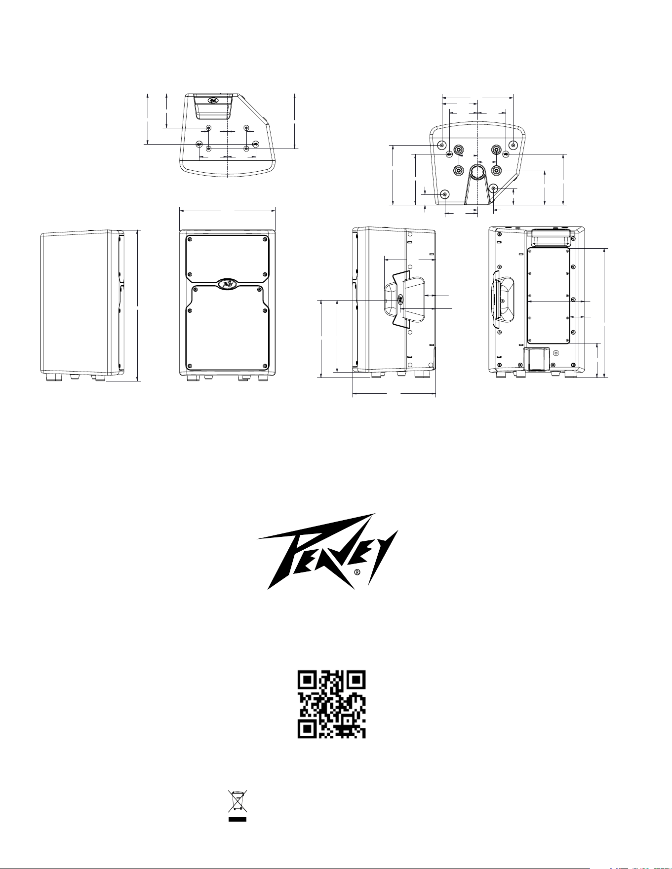
Logo referenced in Directive 2002/96/EC Annex IV
(OJ(L)37/38,13.02.03 and defined in EN 50419: 2005
The bar is the symbol for marking of new waste and
is applied only to equipment manufactured after
13 August 2005
www.peavey.com
Warranty registration and information for U.S. customers available online at
www.peavey.com/warranty
or use the QR tag below
Features and specications subject to change without notice.
Peavey Electronics Corporation 5022 Hartley Peavey Drive Meridian, MS 39305 (601) 483-5365 FAX (601) 486-1278
ARCHITECTURAL AND ENGINEERING SPECIFICATIONS
The passive loudspeaker system shall have a frequency response from 74 Hz to 18 kHz. The peak SPL with inaudible distortion shall reach 122 dB with
music as a source, when measured at a distance of 1M and driven to full output capacity. Power handling shall be rated at 200W continuous, 400W
program and 800W peak. The system shall utilize a Peavey heavy-duty 10" heavy-duty woofer and a Peavey RX 10N dynamic compression driver .
The nominal radiation pattern shall be 100° in the horizontal plane, and 60° in the vertical plane. Axis of the vertical main polar lobe is angled down 10
degrees, resulting in the angular pattern with respect to straight ahead being +20, -40 degrees
The loudspeaker system shall have an input consisting of 1/4" phone jack in parallel with an NL-4 4-pin twist-lock jack on the rear panel. Impedance
shall be 8 ohms nominal.
The input signal shall be divided into high frequencies and low frequencies by a passive high level crossover at 3.0 kHz. The enclosure shall be
constructed of injection-molded ABS with a UL ame rating, and reinforcing ribs internally. A handgrip shall be incorporated on the top rear of the
cabinet, and on the right side.
A separate powder-coated metal grille shall be provided for horn and woofer protection. The cabinet shall incorporate a pole mount for speaker stand
use, four tall sturdy rubber feet for oor standing use, and a group of two widely spaced inserts, and a rectangular grouping of four mounting point
inserts on the top and bottom each, for ying use.
The outside dimensions shall be: 20.00" (50.8 cm) tall x 12.69" (32.2cm) wide x 11.06" (28.1 cm) deep, and the weight shall be 25 lbs (11.3 kg). The
loudspeaker system shall be called a Peavey PVX™10 .
12.690
20.000
11.060
10.303 9.594
4.701
1.479
6.804
1.977
7.547
4.567
17.165
4.528
6.694
6.694
1.378
7.874
2.165
9.449
2.500
2.500
3.740
3.740
2.087
4.331
4.724
6.694
2.500
2.500
4.534
7.283
3.740
3.740
PVX 10
12.690
20.000
11.060
10.303 9.594
4.701
1.479
6.804
1.977
7.547
4.567
17.165
4.528
6.694
6.694
1.378
7.874
2.165
9.449
2.500
2.500
3.740
3.740
2.087
4.331
4.724
6.694
2.500
2.500
4.534
7.283
3.740
3.740
PVX 10
12.690
20.000
11.060
10.303 9.594
4.701
1.479
6.804
1.977
7.547
4.567
17.165
4.528
6.694
6.694
1.378
7.874
2.165
9.449
2.500
2.500
3.740
3.740
2.087
4.331
4.724
6.694
2.500
2.500
4.534
7.283
3.740
3.740
PVX 10
Logo referenced in Directive 2002/96/EC Annex IV
(OJ(L)37/38,13.02.03 and defined in EN 50419: 2005
The bar is the symbol for marking of new waste and
is applied only to equipment manufactured after
13 August 2005
www.peavey.com
Warranty registration and information for U.S. customers available online at
www.peavey.com/warranty
or use the QR tag below
Features and specications subject to change without notice.
Peavey Electronics Corporation 5022 Hartley Peavey Drive Meridian, MS 39305 (601) 483-5365 FAX (601) 486-1278