by
Body-Solid
®
Assembly Instructions
1
Be careful to assemble all components
in the sequence they are presented.
A. Attach Main Base Frame (A) to Rear Base Frame (B) using:
Two 46 (3/8” x 2 3/4” carriage bolts)
Two 53 (3/8” flat washer)
Two 52 (3/8” nylon lock nut)
B. Attach 2 Foot Caps (9) to Rear Base Frame (B) as shown.
C. Attach Vertical Support Pillar (D) and Flat Plate (10) to Main Base Frame (A) using:
Two 42 (3/8” x 2 3/4” hex head bolt)
Four 53 (3/8” flat washer)
Two 52 (3/8” nylon lock nut)
D. Attach Angled Support Pillar (E) to Main Base Frame (A) using:
Two 42 (3/8” x 2 3/4” hex head bolt)
Four 53 (3/8” flat washer)
Two 52 (3/8” nylon lock nut)
E. Attach Convex End Cap (3) to the front of the Main Base Frame (A).
Attach Convex End Cap (3) to the top of the short pillar on top of the Main Base Frame (A).
Attach Rubber Stop (35) with Jam Nut (34) to the short pillar on the Main Base Frame (A)
as shown.
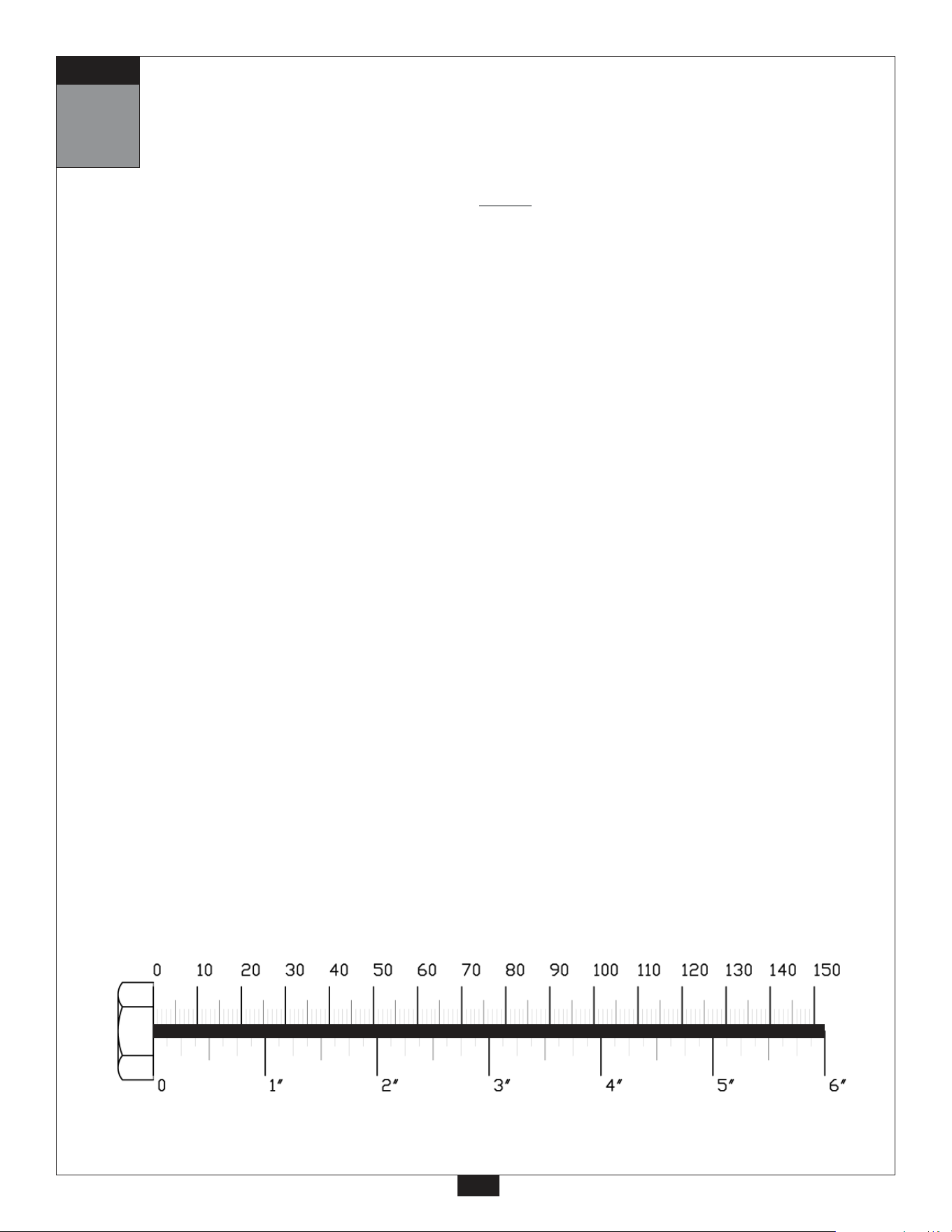
mm
Inch
2
NOTE:
Finger tighten all hardware in this step. Do Not wrench tighten until end of step 6.
STEP
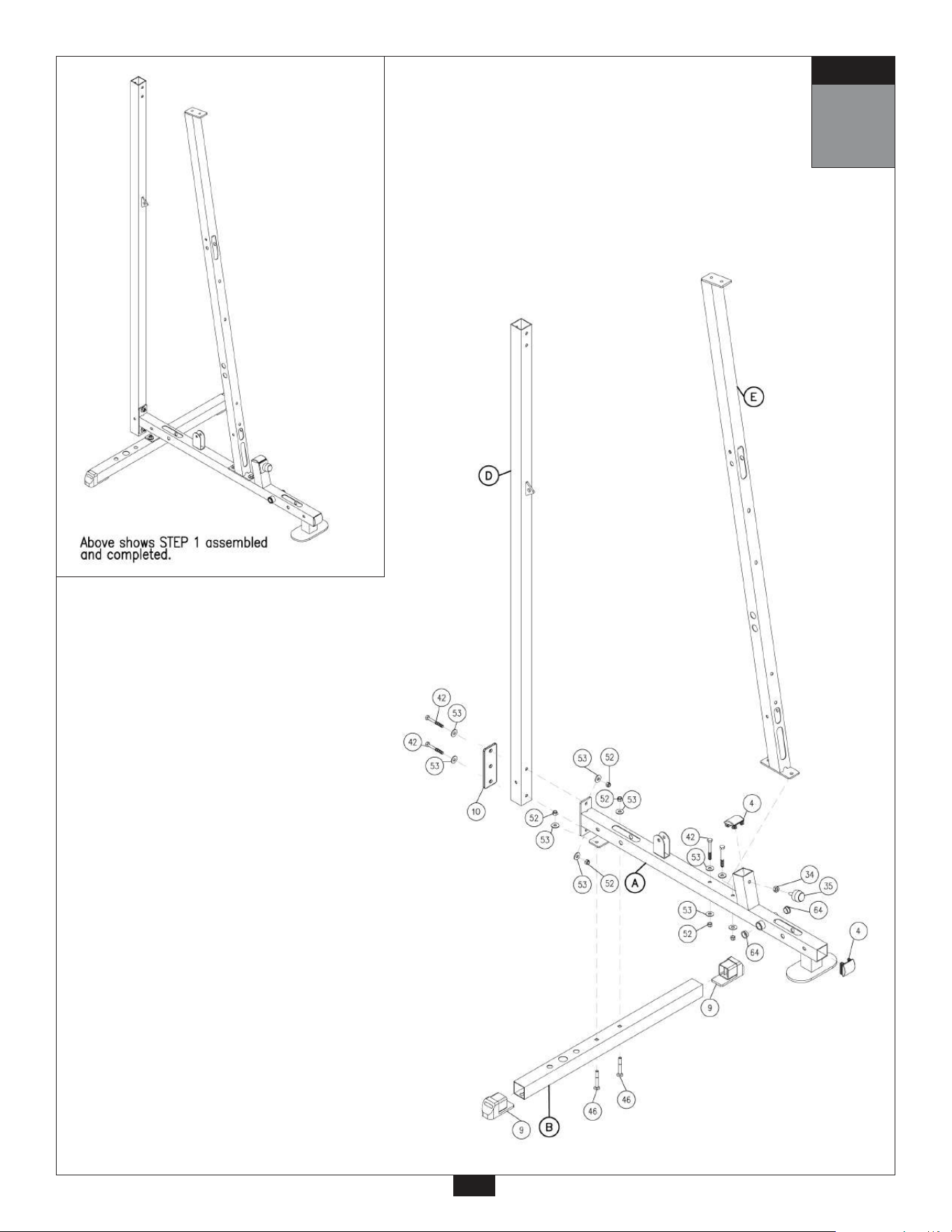
1
3
STEP

A. Attach Top Frame (F) to Angled Support Pillar (E) using:
Two 43 (3/8” x 2 1/2” hex head bolt)
Two 53 (3/8” flat washer)
Note:
Both bolts (43) go into the threaded housing inside the Angled Support Pillar (E)
B. Bolt Top Frame (F) and 2”x4” Plate (G) to Vertical Support Pillar (D) using:
Two 43 (3/8” x 2 1/2” hex head bolt)
Note:
Both bolts (43) go into the threaded housing inside the Vertical Support Pillar (D)
C. Put Foam Roller Bar (H) through Angled Support Pillar (E) and attach two Foam Rollers (18)
with two 1” Roller End Cap (8) as shown. There are two possible openings to mount Foam
Roller Bar (H) to Angled Support Pillar (D). If the main user of this gym is 6’ tall (or more)
mount in the top opening, for shorter people (under 6’) mount in the lower opening. This
piece is not inter-changeable, once these pads are installed they are permanent.
mm
Inch
2
Be careful to assemble all components
in the sequence they are presented.
4
NOTE:
Finger tighten all hardware in this step. Do Not wrench tighten until end of step 6.
STEP
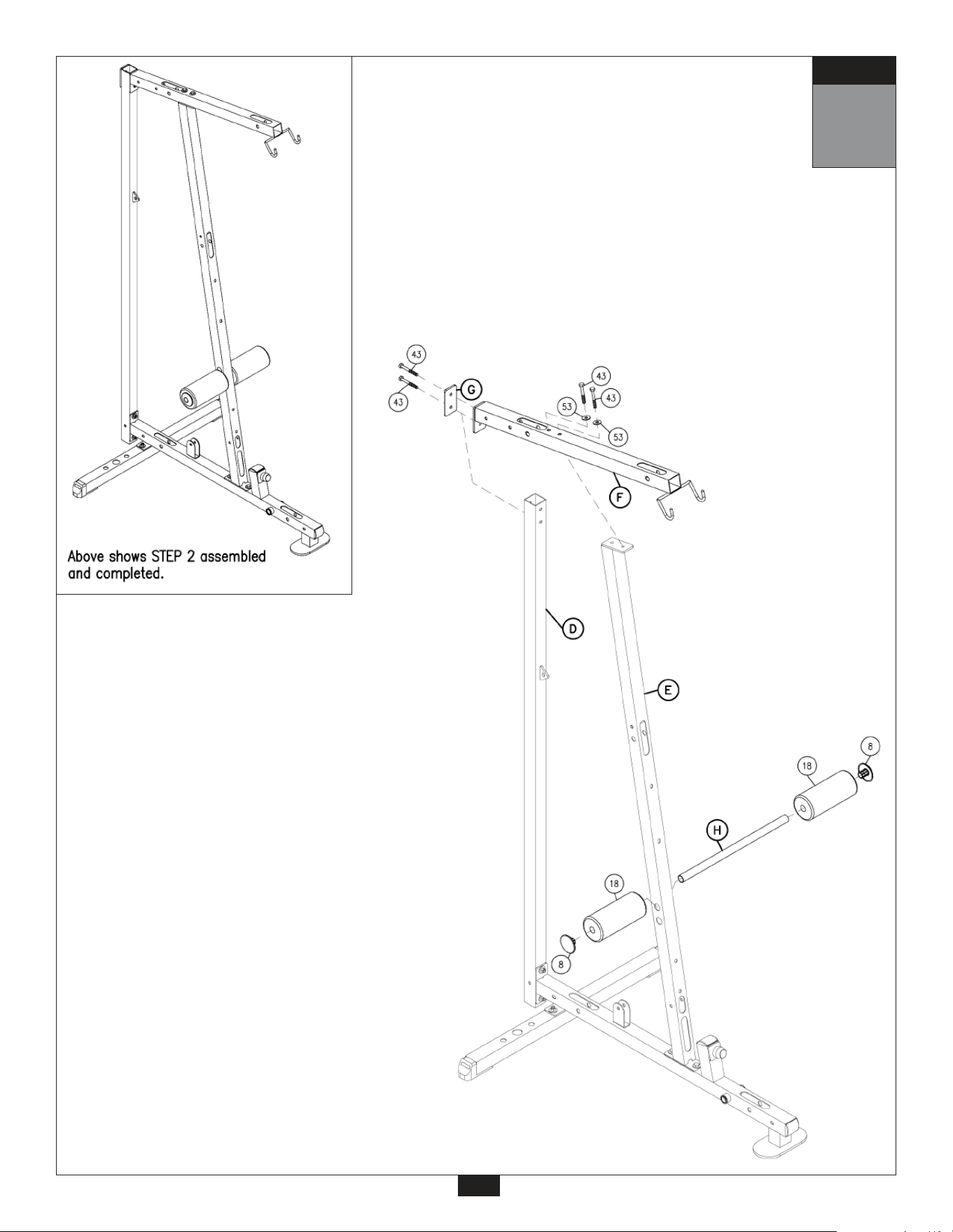
2
5
STEP
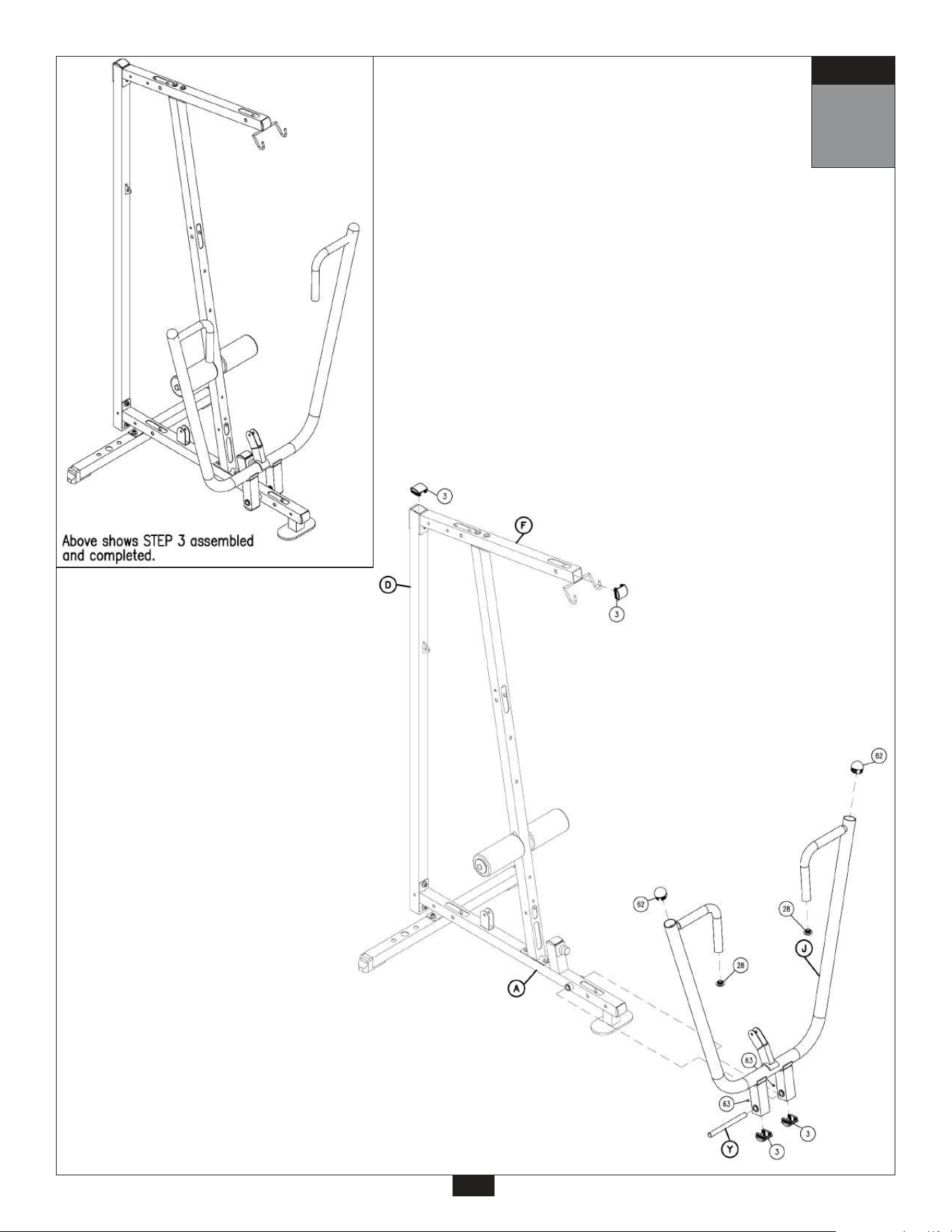
Be careful to assemble all components
in the sequence they are presented.
A. Loosen Allen Head Bolts (63) at the bottom of Bench Press Frame (J).
Slide out Pivot Shaft (Y) from inside of Bench Press Frame (J).
B. Attach Bench Press Frame (J) to Main Base Frame (A) using the Pivot Shaft (Y) as shown.
Retighten Allen Head Bolts (63) at the bottom of Bench Press Frame (J).
C. Attach Convex End Caps (3) to the top of Vertical Support Pillar (D), front of Top Frame (F),
and to the bottom of Bench Press Frame (J) as shown.
mm
Inch
3
6
Note:
Wrench tighten all hardware in this step only. Do not wrench tighten Frame
bolts until after the installation of the weight stack in step 6.
STEP
3
7
STEP
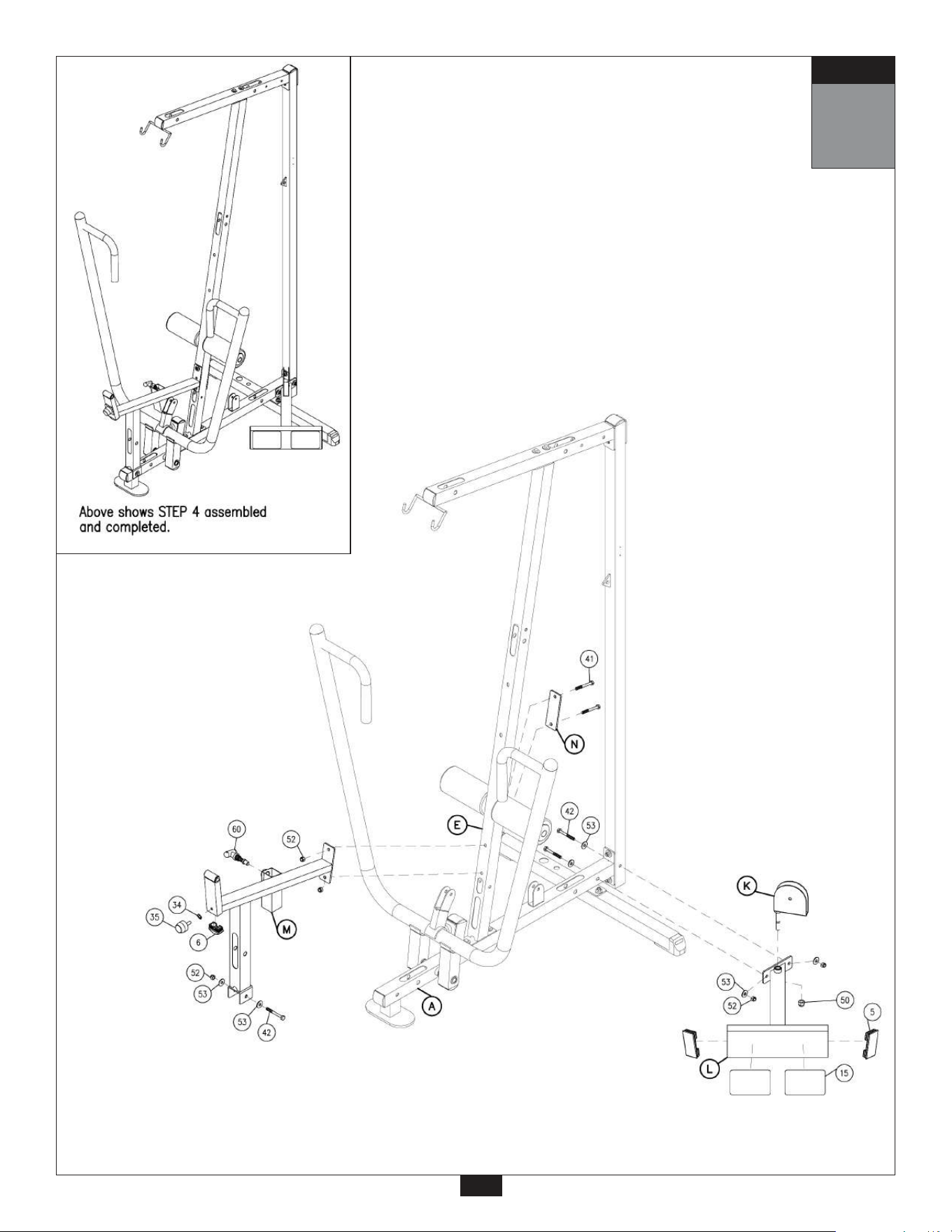
A. Attach Low Pulley Bracket (K) to Foot Brace (L) using:
One 50 (1/2” nylon lock nut)
Note:
Wrench tighten the Nylon Lock Nut (50), but do not over-tighten. Over-tightening will
restrict the Low Pulley Bracket (K) range of motion.
B. Attach Foot Brace (L) to Main Frame (A) using:
Two 42 (3/8” x 2 3/4” hex head bolt)
Four 53 (3/8” flat washer)
Two 52 (3/8”nylon lock nut)
Note:
Foot Brace (L) goes onto the right side of the gym (standing in front, facing the gym).
Make sure holes for the weight stack are on the opposite side (left side).
C. Attach Seat Extension Frame (M) and 2”x5” Plate (N) to Angled Support Pillar (E) using:
Two 41 (3/8” x 3” hex head bolt)
Two 52 (3/8” nylon lock nut)
D. Attach bottom of Seat Extension Frame (M) to Main Base Frame (A) using:
One 42 (3/8” x 2 3/4” hex head bolt)
One 52 (3/8” nylon lock nut)
E. Attach 2 Convex End Caps (5) and Grip Tape (15) to Foot Brace (L) as shown.
Attach 1 Convex End Cap (6) and Rubber Pad (27) to Seat Extension Frame (M) as shown.
Make sure Rubber Stop (35) and Jam Nut (34) is pre-installed into Seat Extension Frame (M).
4
Be careful to assemble all components
in the sequence they are presented.
mm
Inch
8
Note:
Finger tighten all hardware in this step (except where noted in step 4A).
STEP
4
9
STEP

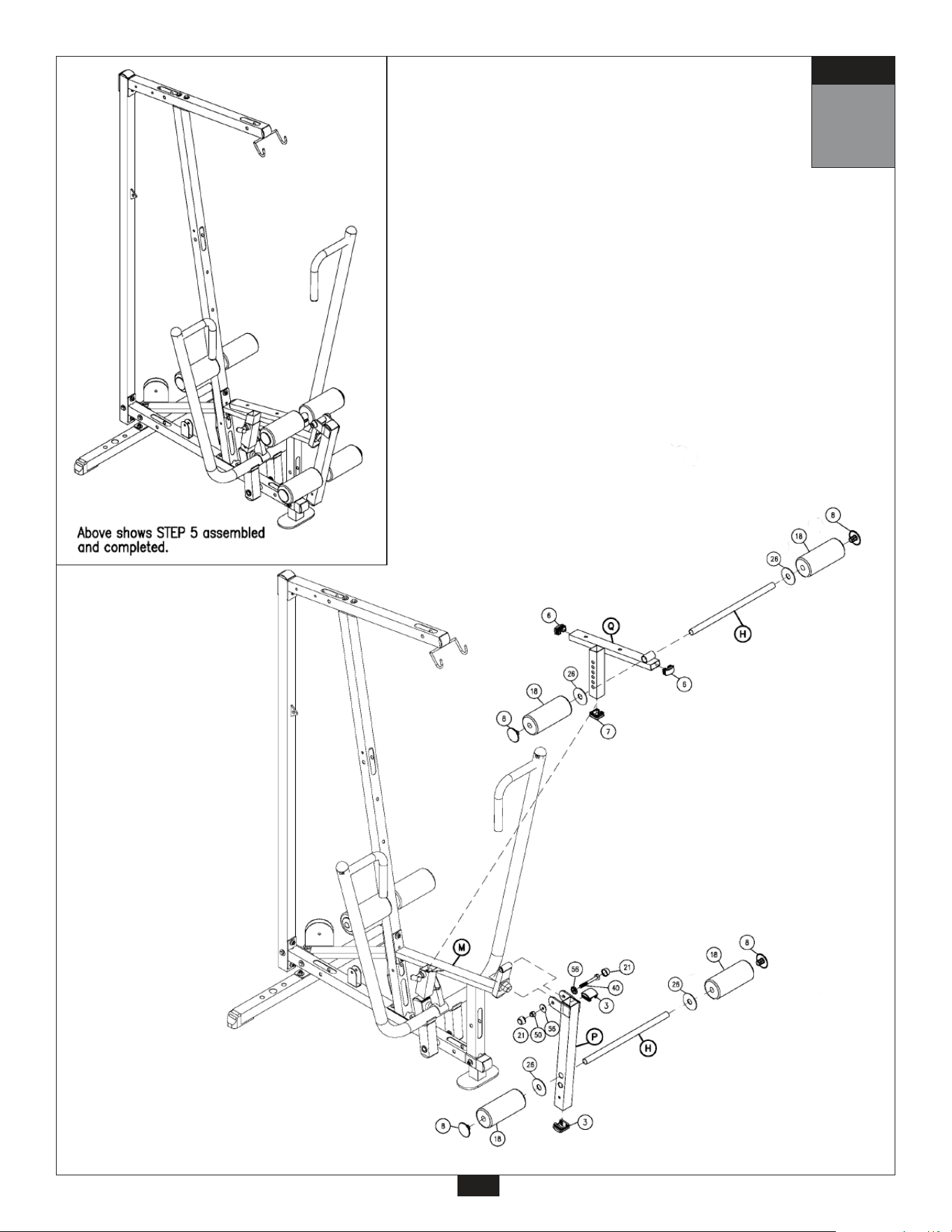
5
Be careful to assemble all components
in the sequence they are presented.
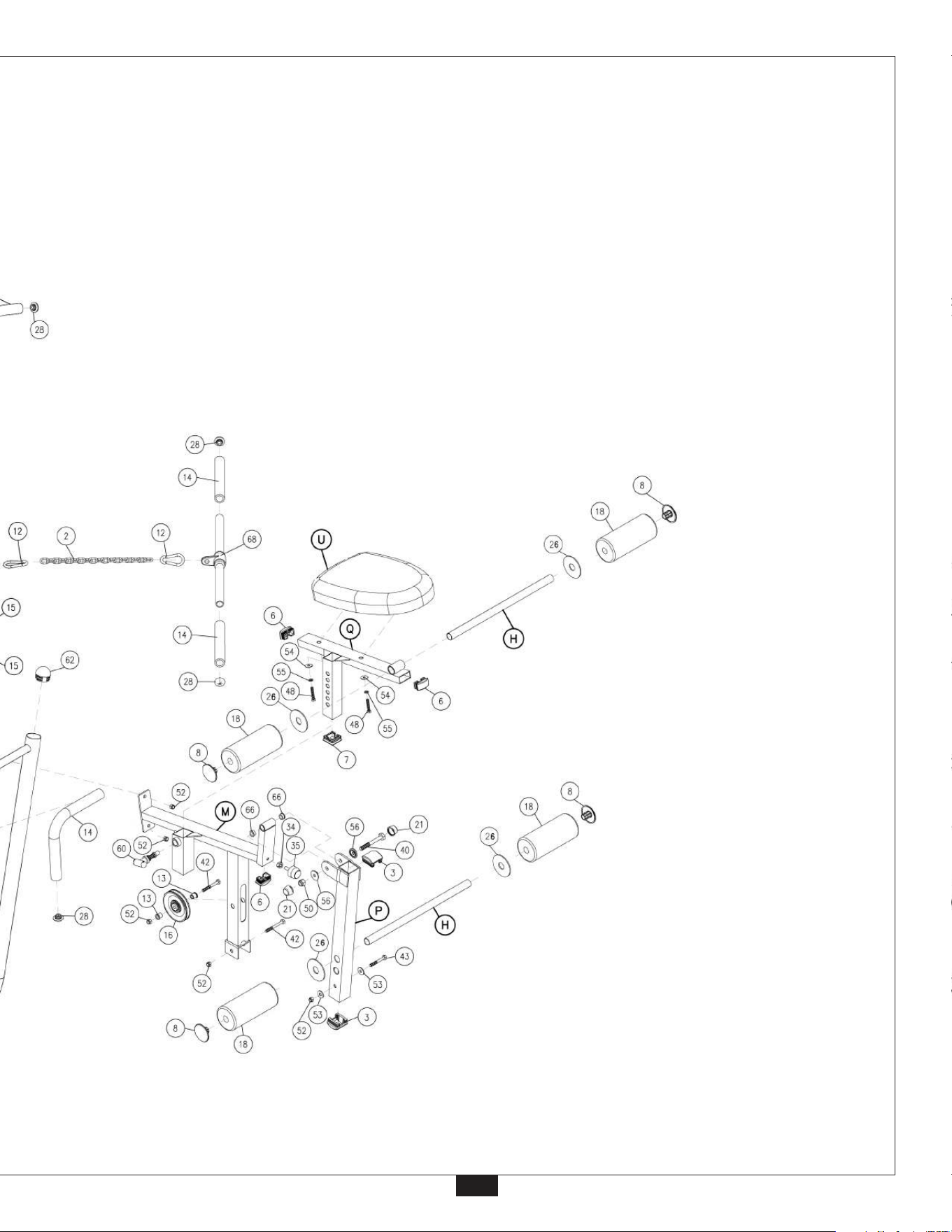
A. Put Foam Roller Bar (H) through Leg Frame (P) and attach 2 Foam Rollers (18) with
3” Plastic Washer (26) on the inside and 1” Roller End Cap (8) on the outside as shown.
Note:
There are two possible holes to mount Foam Roller Bar (H) to Leg Frame (P). If the
main user of this gym is 6’ tall (or more) mount in the lower opening, for shorter
people (under 6’) mount in the top opening. This piece is not inter-changeable,
once these pads are installed they are permanent.
B. Attach Leg Frame (P) to Seat Extension Frame (M) using:
One 40 (1/2” x 3 1/4” hex head bolt)
Two 56 (1/2” round end cap washer)
One 50 (1/2” nylon lock nut)
Two 21 (1/2” bolt cover)
Note:
Wrench tighten bolt (40) only. Leave all other bolts finger tight.
Round End Cap Washers (56) hold Bolt Caps (21) in place.
C. Put Foam Roller Bar (H) through Seat Frame (Q) and attach 2 Foam Rollers (18) with
3” Plastic Washer (26) on the inside and 1” Roller End Cap (8) on the outside as shown.
D. Put two Convex End Caps (3) into the top and bottom of Leg Frame (P). Put 1 3/4” x 1 3/4”
End Cap (7) into the bottom of Seat Frame (Q). Slide Seat Frame (Q) into Seat Extension
Frame (M), hold in place with Threaded Pop Pin (60). Attach two Convex End Caps (6) to the
front and back of Seat Frame (Q) as shown.
mm
Inch
10
Note:
Finger tighten all hardware in this step (except where noted in step 5B).
STEP
5
11
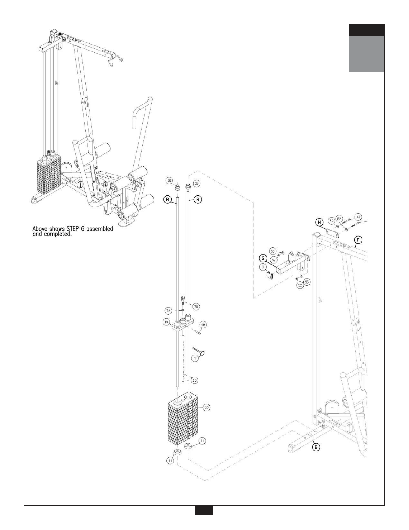
STEP
A. Place two 2 1/2” Rubber Donuts (11) on Rear Base Frame (B) over the two widest openings.
Slide two Chrome Guide Rods (R) through the two 2 1/2” Rubber Donuts (11) and into Rear
Base Frame (B).
B. Slide fifteen Weight Stack Plates (30) onto the two Chrome Guide Rods (R). Make sure
the holes in the Weight Stack Plates (30) are facing forward as shown.
C. Connect Top Plate (19) to Selector Rod (20) using:
One 49 (7/16” x 1” round bolt)
Note:
Selector Rod Top Bolt (70) is preinstalled in Selector Rod (20).
D. Slide Top Plate (19) and Selector Rod (20) onto Guide Rods (R).
Note:
Make sure that the Round Bolt (49) is facing forward as shown.
E. Slide two Shaft Collars (29) onto Guide Rods (R). Make sure the Allen Head Screws inside
the Shaft Collars (29) are loose.
F. Insert two Guide Rods (R) into Top Weight Stack Frame (S).
Attach 2” x 5” Plate (N) and Top Weight Stack Frame (S) to Top Frame (F) using:
Two 41 (3/8” x 3” hex head bolt)
Four 53 (3/8” washer)
Two 52 (3/8” nylon lock nut)
Insert Convex End Cap (3) into Top Weight Stack Frame (S) as shown.
G. Secure two Shaft Collars (29) into Top Weight Stack Frame (S). Tighten the Allen Head
Screws in each Shaft Collar.
H. You should now wr
ench tighten all bolts and nuts on the main frame unit.
6
Be careful to assemble all components
in the sequence they are presented.
mm
Inch
12
STEP
6
13
STEP
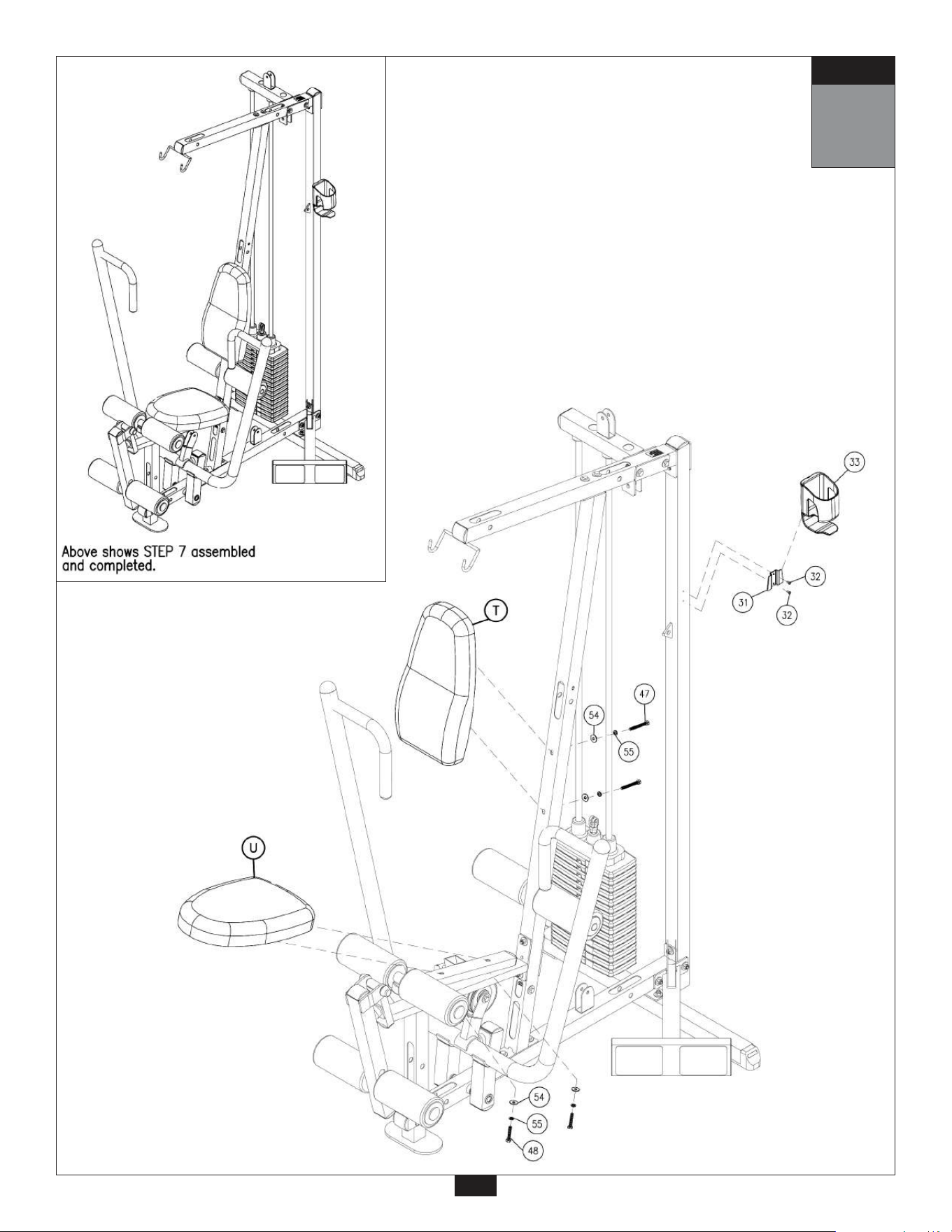
A. Attach Back Pad (T) to Angled Support Pillar (E) using:
Two 47 (5/16” x 2 3/4” hex head bolt)
Two 55 (5/16” spring lock washer)
Two 54 (5/16” flat washer)
Note:
Do not over tighten Pad Bolts (47), over tightening will strip the T-nuts pressed into
the wood.
B. Attach Seat Pad (U) to Seat Frame (J) using:
Two 48 (5/16” x 1 3/4” hex head bolt)
Two 55 (5/16” spring lock washer)
Two 54 (5/16” flat washer)
Note:
Do not over tighten Pad Bolts (48), over tightening will strip the T-nuts pressed into
the wood
.
C. Connect the Water Bottle Bracket (31) to the Vertical Support Pillar (D) using:
Two 32 (1/8” x 3/8” screw)
D. Slide the Water Bottle Holder (33) onto the Water Bottle Bracket (31) as shown.
7
Be careful to assemble all components
in the sequence they are presented.
mm
Inch
14
STEP
7
15
STEP
8
Be careful to assemble all components
in the sequence they are presented.
mm
Inch
Note:
All Pulleys in this step are 4 1/4” diameter, except where noted in step 8B.
Leave all pulley bolts hand tight until step 12 is completed.
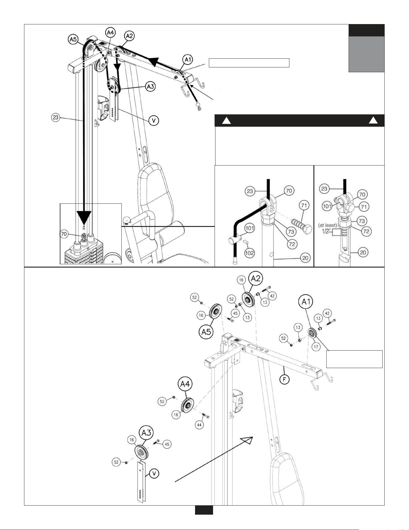
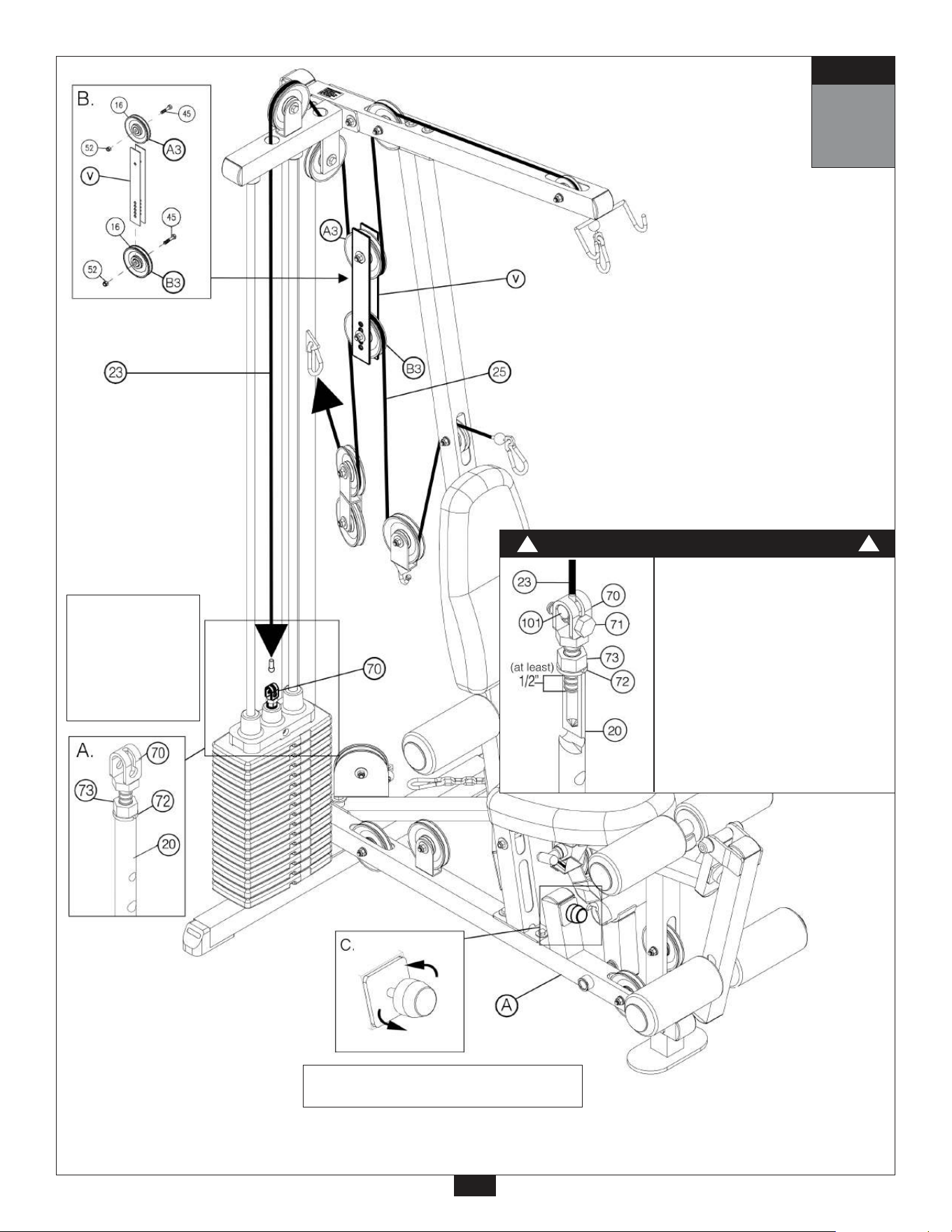
A. See diagram 1. Begin at the high pulley station. Route the metal ball end of Lat Cable (23) up and through
the opening where the Pulley (A1) will be installed and then down through the next opening where
Pulley (A2) will be installed.
B. See diagram 2. Install 3 1/2” diameter Pulley (A1), under Cable (23) and into Top Frame (F) as shown.
Install Pulley (A2) into Top Frame (F) under Cable (23) using:
Two 42 (3/8” x 2 3/4” hex head bolt)
Four 13 (pulley spacer)
Two 52 (3/8” nylon locknut)
C. Route Cable (23) through the top portion of the Adjustable Double Bracket (V) as shown in diagram 1.
Hold Cable (23) in place by installing Pulley (A3) as shown in diagram 2 using:
One 45 (3/8” x 1 3/4” hex head bolt)
One 52 (3/8” nylon locknut)
D. See diagram 1. Route Cable (23) up and through the opening above where Pulley (A4) will be installed and
then down and through the opening next to Pulley (A5) as shown.
E. Install Pulley (A5) to the top of the Top Weight Stack Frame (S), as shown using:
One 45 (3/8” x 1 1/2” hex head bolt)
One 52 (3/8” nylon lock nut)
Install Pulley (A4) to the bottom of the Top Weight Stack Frame (S), as shown using:
One 44 (3/8” x 1 3/4” hex head bolt)
One 52 (3/8” nylon lock nut)
F. See diagram 1A. The Metal Ball End of Cable (23) should be hanging just above the Weight Stack. Remove
Bolt (71) from Selector Rod Top Bolt (70), slide Metal Ball End of Cable (23) through Selector Rod Top
Bolt (70). Attach Cable End Shaft (101) and securely tighten Allen Screw (102). Pull Cable (23) tight, so
Cable End Shaft (101) fits securely inside Selector Rod Top Bolt (70). Reinstall Bolt (71) in Selector Rod
Top Bolt (70).
Note:
Make sure the Selector Rod Top Bolt (70) is threaded inside Selector Rod (20) at least one half
inch. Make sure Spring Lock Washer (72) is in place and wrench tighten Jam Nut (73).
16
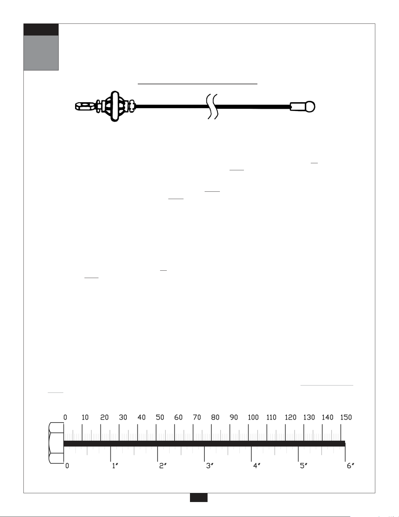
Ball Stop End
Metal Ball End
3225 mm
10’ 7”
Lat Pulldown Cable (23)
STEP
Start at high pulley station by inserting the
Metal Ball End here.
8
17
Lat Pulldown
Cable
Selector Rod Top Bolt (70) must be threaded a minumum of
1/2” into the Selector Rod (20), and Jam Nut (73) tightened
securely against spring lock washer (72) to ensure proper
connection. Check the Jam Nut (73) once a week to make
sure it is tight.
Diagram 1
Cable Installation
Diagram 2
Pulley Installation
WARNING
!
!
Diagram 1A
STEP
3 1/2” diameter
pulley
3 1/2” diameter pulley
9
Be careful to assemble all components
in the sequence they are presented.
mm
Inch
18
Note:
All Pulleys in this step are 4 1/4” diameter, except where noted in step 9B.
Leave all pulley bolts hand tight until step 12 is completed.
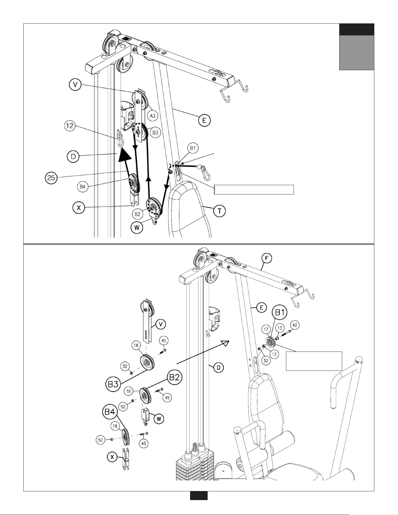
A. See diagram 1. Insert stamped eye end of the Ab Crunch Cable (25) into the opening in Angled
Support Pillar (E), above Back Pad (T), and pull entire length through.
B. Install 3 1/2” diameter Pulley (B1), under Cable (25) and into Angled Support Pillar (E) as shown
in diagram 2 using:
One 42 (3/8” x 2 3/4” hex head bolt)
Two 13 (pulley spacer)
One 52 (3/8” nylon lock nut)
C. Route Cable (25) through Single Pulley Hook (W) as shown in diagam 1 and hold cable in place
by installing Pulley (B2) using:
One 45 (3/8” x 1 1/2” hex head bolt)
One 52 (3/8” nylon lock nut)
D. See diagram 1. Route Cable (25) up through the bottom of Adjustable Double Bracket (V),
and hold cable in place by installing Pulley (B3) as shown using:
One 45 (3/8” x 1 1/2” hex head bolt)
One 52 (3/8” nylon lock nut)
E. Attach the stamped eye end of Cable (25) to the Vertical Support Pillar (D) with a Snap Link (12)
as shown in diagram 1.
F. See diagram 1. Take up the slack in the cable by hanging the Double Bracket (X) in the proper
position and install Pulley (B4) as shown in diagram 2 using:
One 45 (3/8” x 1 1/2” hex head bolt)
One 52 (3/8” nylon lock nut)
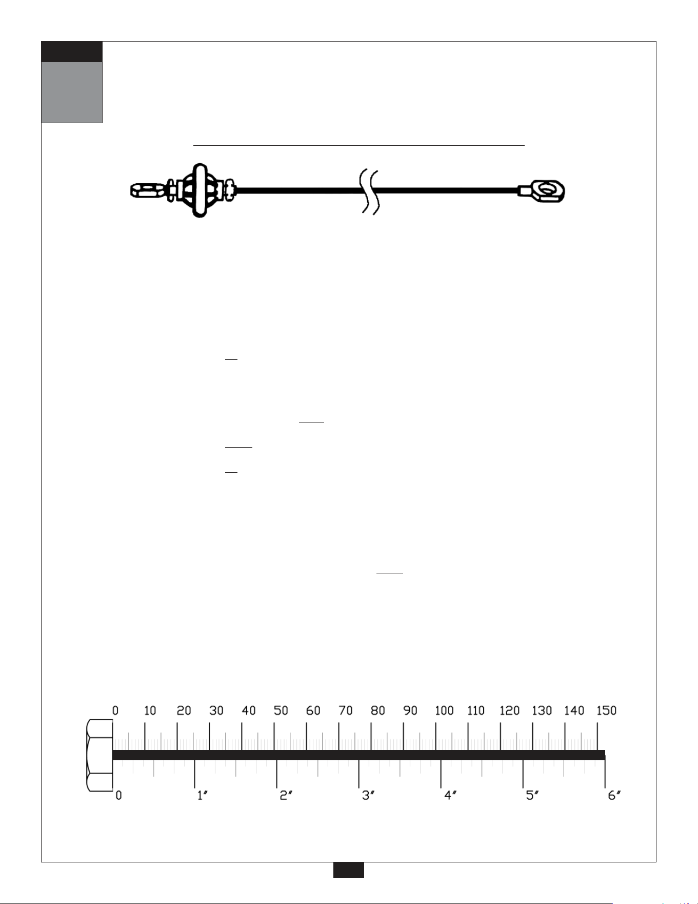
Ab Cr
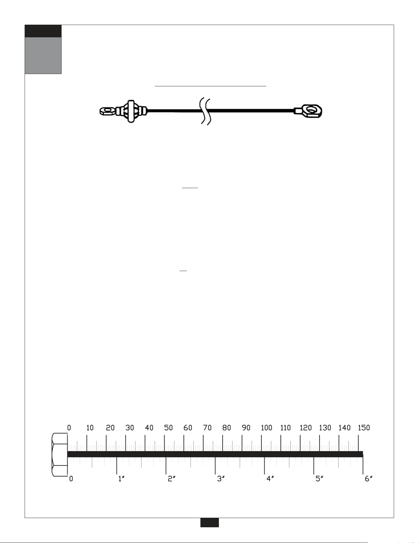
unch Cable (25)
Ball Stop End
Stamped Eye End
2480 mm
8’ 1”
STEP
Start here at ab crunch station by inserting
the Stamped Eye End here.
9
19
Ab Crunch
Cable
Diagram 1
Cable Installation
3 1/2” diameter
pulley
3 1/2” diameter pulley
STEP
Diagram 2
Pulley Installation
10
Be careful to assemble all components
in the sequence they are presented.
mm
Inch
Note:
All Pulleys in this step are 4 1/4” diameter.
Leave all pulley bolts hand tight until step 12 is completed.
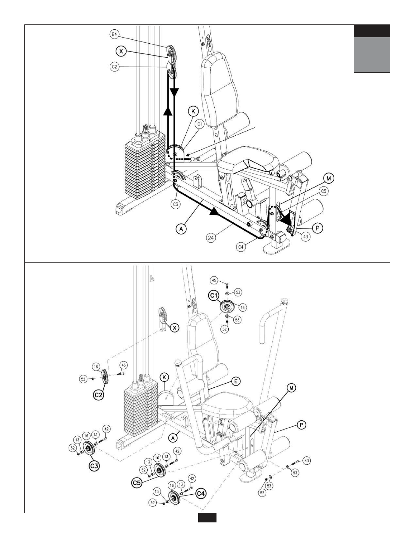
A. See diagram 1. Insert stamped eye end of the Low Pulley / Leg Extension Cable (24) through
Low Pulley Bracket (K) and install Pulley (C1) as shown using:
One 45 (3/8” x 1 1/2” hex head bolt)
Two 53 (3/8” flat washer)
One 52 (3/8” nylon lock nut)
B. Route Cable (24) up and through the bottom portion of the Double Pulley Bracket (X), and hold
Cable (24) in place by installing Pulley (C2) as shown using:
One 45 (3/8” x 1 1/2” hex head bolt)
One 52 (3/8” nylon lock nut)
C. See diagram 1. Route Cable (24) down and through the hole in the Main Base Frame (A), where
Pulley (C3) will be installed.
Route Cable (24) under Main Base Frame (A).
D. Route Cable (24) up and through the opening in the Main Base Frame (A) where Pulley (C4) will
be installed.
Route Cable (24) through the opening in the Seat / Extension Frame (M). Attach Stamped eye
end of Cable (24) to the Leg Frame (P) as shown in diagram 2 using:
One 42 (3/8” x 2 3/4” hex head bolt)
Two 13 (pulley spacer)
One 52 (3/8” nylon lock nut)
E. Insert Pulley (C5) into Seat / Extension Frame (M), under
Cable (24), as shown using:
One 42 (3/8” x 2 3/4” hex head bolt)
Two 13 (pulley spacer)
One 52 (3/8” nylon lock nut)
F. Take up the slack in the Cable (24) by installing Pulleys (C3) and (C4) into Main Base Frame (A)
as shown in diagram 2 using for each pulley:
One 42 (3/8” x 2 3/4” hex head bolt)
Two 13 (pulley spacer)
One 52 (3/8” nylon lock nut)
20
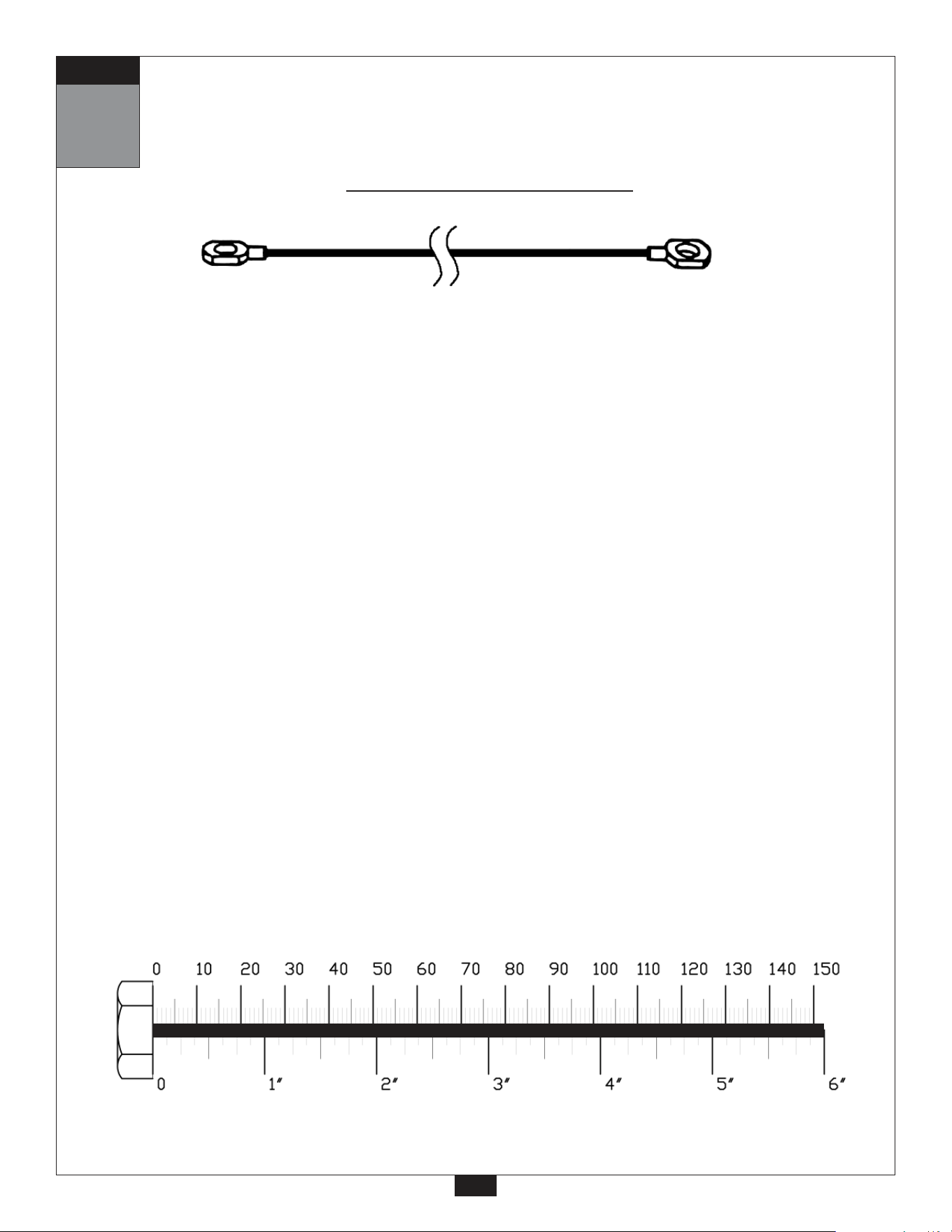
Low Pulley / Leg Extension Cable (24)
Ball Stop End
Stamped Eye End
3050mm
10’
STEP
10
Start at low pulley station by inserting
the Stamped Eye End here.
21
Low Pulley / Leg
Extension Cable
Diagram 1
Cable Installation
Diagram 2
Pulley Installation
STEP
Note:
All Pulleys in this step are 4 1/4” diameter.
Leave all pulley bolts hand tight until step 12 is completed.
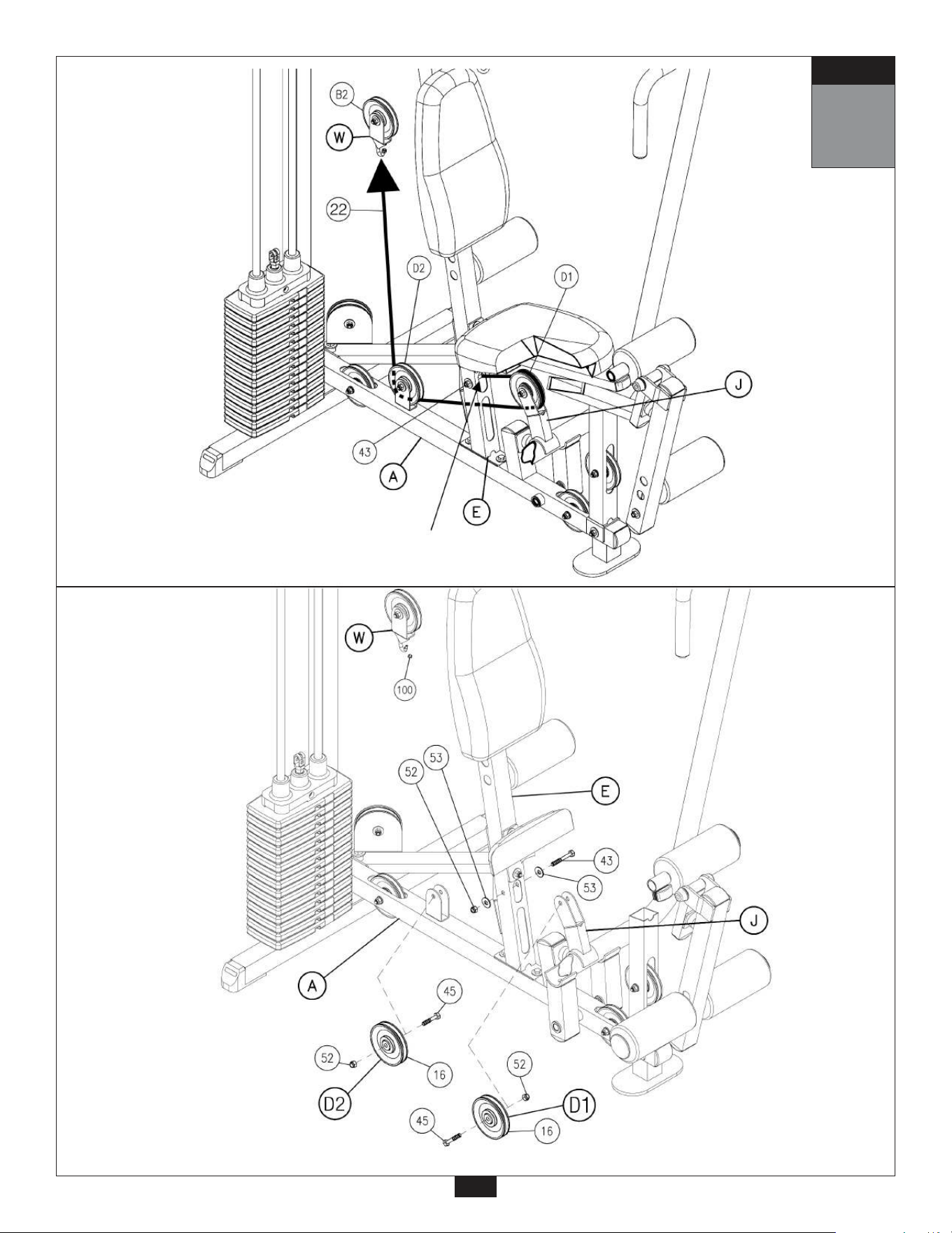
A. See diagram 1. Attach either end of Seated Press Cable (22) to Angled Support Pillar (E) as
shown using:
One 43 (3/8” x 2 1/2” hex head bolt)
Two 53 (3/8” flat washer)
One 52 (3/8” nylon lock nut)
B. Route Cable (22) through the pulley bracket on Bench Press Frame (J) and install Pulley (D1)
as shown using:
One 45 (3/8” x 1 1/2” hex head bolt)
One 52 (3/8” nylon lock nut)
C. Route Cable (22) through Angled Support Pillar (E) as shown in diagram 1.
D. Route Cable (22) through pulley bracket where Pulley (D2) will be installed and hold cable in
place by installing Pulley (D2) as shown in diagram 2 using:
One 45 (3/8” x 1 1/2” hex head bolt)
One 52 (3/8” nylon lock nut)
E. Connect the end of Cable (22) to the hook on the bottom of Single Pulley Hook (W) as shown in
diagram 1.
11
Be careful to assemble all components
in the sequence they are presented.
mm
Inch
22
Seated Press Cable (22)
Stamped Eye End
Stamped Eye End
1440 mm 4’ 8.5”
STEP
Start here by attaching the
Seated Press Cable to the
Angled Support Pillar.
11
23
Seated Press
Cable
Diagram 1
Cable Installation
Diagram 2
Pulley Installation
STEP
12
Be careful to assemble all components
in the sequence they are presented.
NOW IS THE TIME TO MAKE ALL NECESSARY
CABLE ADJUSTMENTS
After cable installation is complete you must check all cables for proper tension. Obvious signs that
cable tension problems exist include:
c Top Plate (19) does not rest directly on the top Weight Stack Plate (30).
c The holes in the Selector Rod (20) do not line up with holes in the Weight Stack Plates (30).
c Cable(s) are sloppy and there is no resistance from the weight stack for the first few
inches of the exercise.
There are Three areas for cable adjustment on the G1S:
A. Selector Rod Top Bolt (70)
B. Adjustments in Adjustable Double Bracket (V).
C. Rubber Stop (35) on Main Base Frame (A).
SEE NOTE 1 ON PAGE 25
If there is to much tension, and the Top Plate (19) is not resting directly on top of the weight stack plates:
1st. -Tighten Rubber Stop (35).
2nd. -Move Pulley (B3) down to a lower hole in Adjustable Double Bracket (V), or move
Pulley (A3) up to a higher hole in Adjustable Double Bracket (V).
If there is to much play or excessive slack;
1st. -Loosen Rubber Stop (35).
2nd. -Move Pulley (B3) up to a higher hole in Adjustable Double Bracket (V), or move
Pulley (A3) down to a lower hole in Adjustable Double Bracket (V).
3rd. -Screw the Selector Rod Top Bolt (70) farther into the Selector Rod (20) of the weight stack.
NOTE:
Cables should be inspected daily and adjusted periodically to ensure safe and
smooth operation.
NOTE:
After cable adjustment is complete, you should now wrench tighten all bolts.
Do NOT re-tighten any pad bolts.
24
STEP
Selector Rod
Top Bolt
NOTE 1
Check Jam Nut (73)
weekly to be sure it
is tight and locked
onto the Selector
Rod (20).
12
STEP
25
Loosen
Turn and loosen Rubber Stop (35) to take
up space and tighten cable.
Selector Rod Top Bolt (70)
must be threaded a
minumum of 1/2” into the
Selector Rod (20), and
Jam Nut (73) tightened
securely against spring
lock washer (72) to ensure
proper connection.
WARNING
!
!

Part numbers are required when ordering parts.
G1S Mainframe Parts List
KEY# QTY PART# DESCRIPTION
A
B
D
E
F
G
H
J
K
L
M
N
P
Q
R
S
V
W
X
1
1
1
1
1
1
3
1
1
1
1
2
1
1
2
1
1
1
1
G1SMBF-A
G1SRBF-B
G1SVSP-D
G1SASP-E
G1STF-F
G1SP-G
G1SFRB-H
G1SBPF-J
G1SLPB-K
G1SFB-L
G1SSEF-M
G1SP-N
G1SLF-P
G1SSF-Q
G1SCGR-R
G1STWSF-S
G1SWADB-V
G1SSPH-W
G1SWDB-X
MAIN BASE FRAME
REAR BASE FRAME
VERTICAL SUPPORT PILLAR
ANGLED SUPPORT PILLAR
TOP FRAME
2”X4” PLATE
FOAM ROLLER BAR
BENCH PRESS FRAME
LOW PULLEY BRACKET
FOOT BRACE
SEAT/EXTENSION FRAME
2” X 5 1/2” PLATE
LEG FRAME
SEAT FRAME
CHROME GUIDE ROD
TOP WEIGHT STACK FRAME
ADJUSTABLE DOUBLE BRACKET
SINGLE PULLEY HOOK
DOUBLE BRACKET
26

G1S Hardware List
Part numbers are required when ordering parts.
KEY# QTY PART# DESCRIPTION
27
Continued on next page
1
2
3
4
5
6
7
8
9
10
11
12
13
15
16
17
18
19
20
21
26
27
28
29
30
31
32
33
34
35
1
1
7
2
2
3
1
6
2
1
2
5
12
2
14
2
6
1
1
2
4
1
6
2
15
1
2
1
2
1
JPIN4.25
JSCH.18
JCEC22
JCEC22LE
JCEC24
JCEC12
JCEC1.75X1.75
JREC1
JFC22
JFP22.5
JRD2.5
JSNAP3
JPS.62X.37
JGT5.5
JPP4.25W.75
JPP3.5W.75
JFOAM3.5x8
JTP10
JSR15
JBC.5
JPW3
JRP1.5X1.75
JREC1.5
JSC1.37X.75
JSP10
JWBB
JS.125X.37FT
JWBH
JJN.37
JRS1.5
WEIGHT STACK PIN 4 1/4” X 7/16”
STEEL CHAIN 3/16”
CONVEX END CAP 2” X 2” I.D. 1 3/8”
CONVEX END CAP 2” X 2” I.D. 1 7/16”
CONVEX END CAP 2” X 4”
CONVEX END CAP 1” X 2”
END CAP 1 3/4” X 1 3/4”
ROLLER END CAP 1”
FOOT CAP 2” X 2”
FLAT PLATE 2” X 5 1/2”
RUBBER DONUT 2 1/2”
SNAP LINK
PULLEY SPACER 5/8” OD X 3/8” ID X 5/8” L
GRIP TAPE 5 1/2” X 3 3/4”
PLASIC PULLEY 4 1/4” X 3/4” WIDE
PLASIC PULLEY 3 1/2” X 3/4” WIDE
FOAM ROLLER 3 1/2” X 8”
TOP PLATE (10 lbs.)
SELECTOR ROD (15 selector holes)
BOLT COVER 1/2”
PLASIC WASHER 3”
RUBBER PAD 1 1/2” X 1 3/4”
ROUND END CAP 1 1/2”
SHAFT COLLAR 1 3/8” OD X 3/4” ID 1.5” L
WEIGHT PLATE
WATER BOTTLE BRACKET
SCREW 1/8” X 3/8” FULL THREAD
WATER BOTTLE HOLDER
JAM NUT 3/8”
RUBBER STOP (1 1/2” diameter)

28
G1S Hardware
(continued)
KEY# QTY PART# DESCRIPTION
40
41
42
43
44
45
46
47
48
49
50
52
53
54
55
56
60
62
63
64
65
66
70
71
72
73
100
101
102
103
1
4
13
6
1
9
2
2
2
1
2
32
32
4
4
2
1
2
2
2
2
2
1
1
1
1
1
1
1
1
JHEX.5X3.25PTB
JHEX.37X3PTB
JHEX.37X2.75PTB
JHEX.37X2.5PTB
JHEX.37X1.75PTB
JHEX.37X1.5PTB
JCB.37X2.75PTB
JHEX.31X2.75PTB
JHEX.31X1.75PTB
JRAH.43X1.5PTB
JNLN.5
JNLN.37
JWFLT.37
JWFLT.31
JWSW.31
JREC.5
JTSPP3
JREC2
JAS.31X.31
JBB.87X.75
JBB.75X.5
JBB.75X.5
JSRTB.5
JHEX.37X.87FTB
JSLW.5
JJN.5
JACN.19
JCES
JAS.125X.25
JWSPL
HEX HEAD BOLT 1/2” X 3 1/4” PARTIAL THREAD
HEX HEAD BOLT 3/8” X 3” PARTIAL THREAD
HEX HEAD BOLT 3/8” X 2 3/4” PARTIAL THREAD
HEX HEAD BOLT 3/8” X 2 1/2” PARTIAL THREAD
HEX HEAD BOLT 3/8” X 1 3/4” PARTIAL THREAD
HEX HEAD BOLT 3/8” X 1 1/2” PARTIAL THREAD
CARRIAGE BOLT 3/8” X 2 3/4” PARTIAL THREAD
HEX HEAD BOLT 5/16” X 2 3/4” PARTIAL THREAD
HEX HEAD BOLT 5/16” X 1 3/4” PARTIAL THREAD
ROUND ALLEN HEAD 7/16” X 1 1/2” PARTIAL THREAD
NYLON LOCK NUT 1/2”
NYLON LOCK NUT 3/8”
WASHER 3/8”
WASHER 5/16”
SPRING LOCK WASHER 5/16”
ROUND END CAP WASHER 1/2”
T-SHAPED POP PIN 3” L
ROUND END CAP 2”
ALLEN SCREW 5/16” X 5/16” FULL THREAD
OILITE BUSHING 7/8”OD 3/4”ID - PREINSTALLED
OILITE BUSHING 3/4”OD 1/2”ID 7/16”L- PREINSTALLED
OILITE BUSHING 3/4”OD 1/2”ID 7/16”L- PREINSTALLED
SELECTOR ROD TOP BOLT 1/2” X 2” FULL THREAD
HEX HEAD BOLT 3/8” X 7/8” FULL THREAD
SPRING LOCK WASHER 1/2”
JAM NUT 1/2”
ACORN CAP NUT 3/16” ID - PREINSTALLED
CABLE END SHAFT 3/4” L
ALLEN SCREW 1/8” X 1/4” FULL THREAD
WEIGHT STACK PIN LANYARD
Part numbers are required when ordering parts.

Pads List
Part numbers are required when ordering parts.
Cable List
Accessories List
KEY# QTY PART# DESCRIPTION
KEY# QTY PART# DESCRIPTION
KEY# QTY PART# DESCRIPTION
T
U
1
1
G1SBP-T
G1SSP-U
BACK PAD
SEAT PAD
22
23
24
25
1
1
1
1
JSPC1440
JLP3240
JLP3050
JACC2210
SEATED PRESS CABLE
LAT PULLDOWN CABLE
LOW PULLEY / LEG EXTENSION CABLE
AB CRUNCH CABLE
29
LAT BAR
LOW ROW BAR
LAT BAR PAD
FOAM GRIP 1 1/2” OD X 18” L -PREINSTALLED
FOAM GRIP 1 1/2” OD X 8 1/2” L -PREINSTALLED
FOAM GRIP 1 1/2” OD X 14” L -PREINSTALLED
67
68
69
80
81
82
1
1
1
2
2
2
JE15LB
JE15LRB
JE15LBP
JFG18
JFG8.5
JFG14
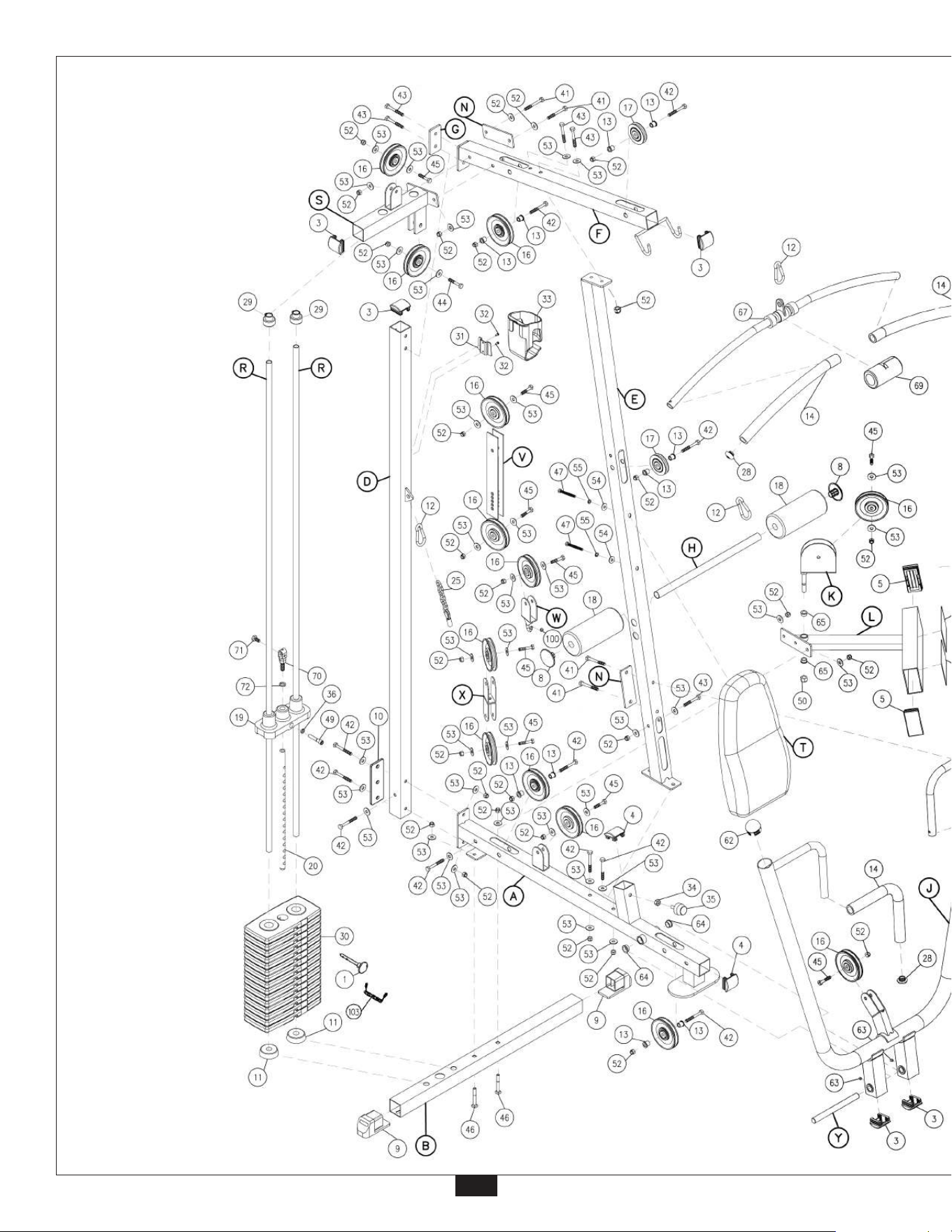
30
EXPLODED VIEW
DIAGRAM
G1S
© Copyright 2003. Body-Solid. All rights reserved. Body-Solid reserves the right to change design and specifications when we feel it will improve the product.
Body-Solid machines maintain several patented and patent pending features and designs. All rights reserved on all design patents and utility patents.
31
