Body-Solid
®
Assembly Instructions
1
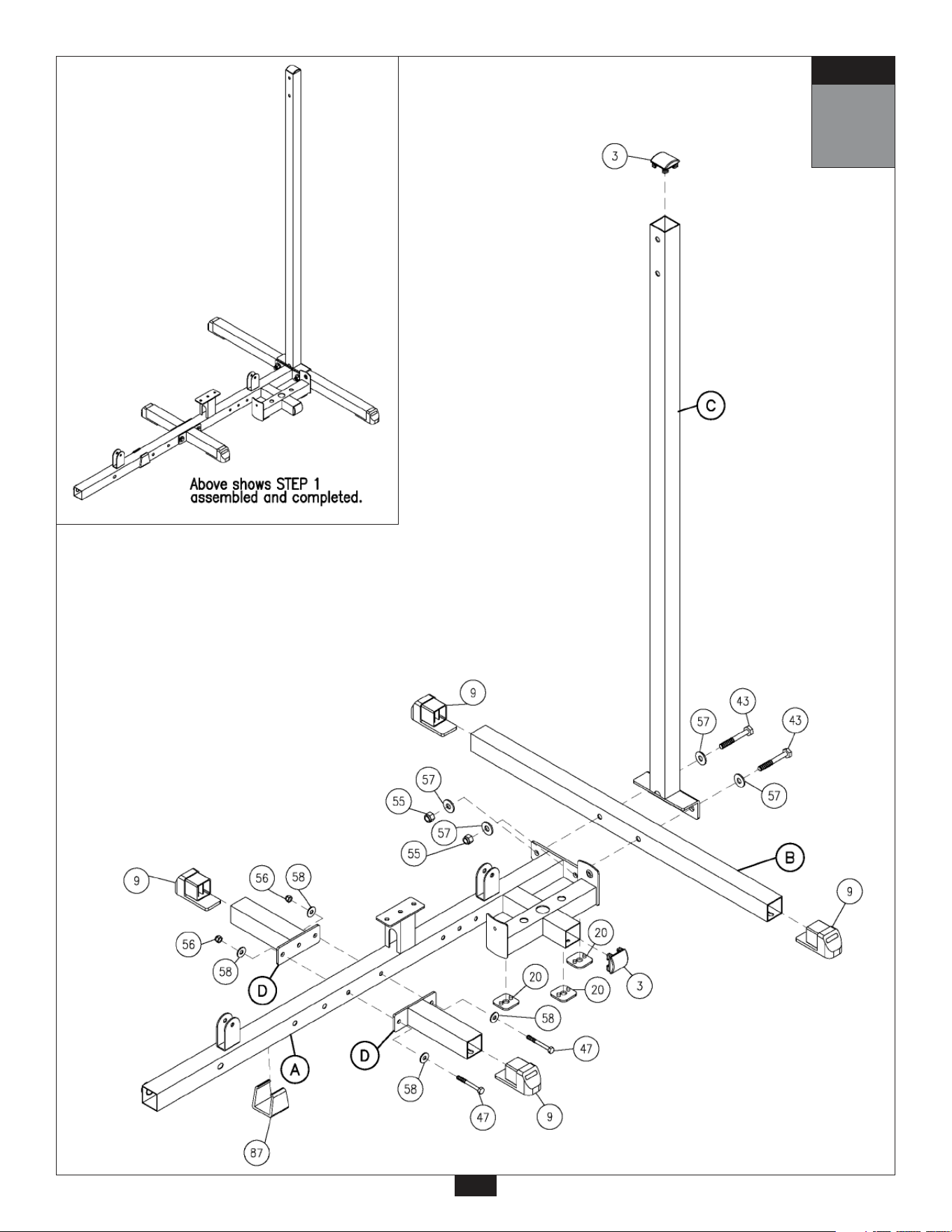
Be careful to assemble all components
in the sequence they are presented.
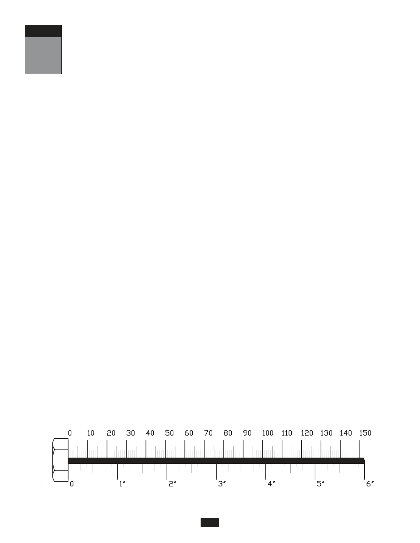
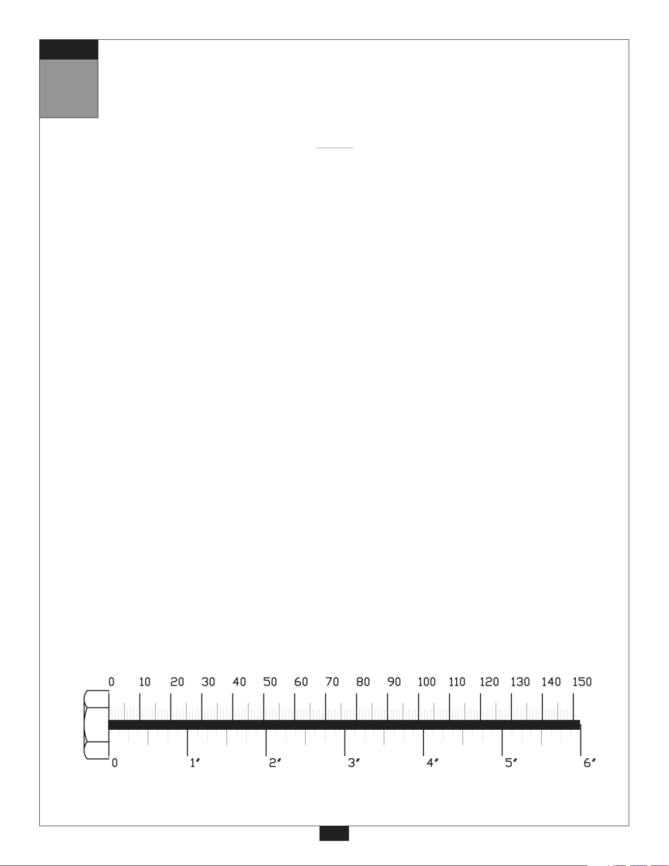
mm
Inch
A. Insert two Foot Caps (9) into the ends of Rear Base Frame (B). Insert Convex End Cap (3) to
the top of Rear Vertical Frame (C).
B. Attach Main Base Frame (A) to Rear Base Frame (B) and Rear Vertical Frame (C) using:
Two 52 (1/2” x 3 1/2” hex head bolt)
Four 57 (1/2” washer)
Two 55 (1/2” nylon lock nut)
C. Insert two Foot Caps (9) to the ends of Side Base Frame (D).
D. Attach two Side Base Frames (D) to Main Base Frame (A) using:
Two 47 (3/8” x 3” hex head bolt)
Four 58 (3/8” washer)
Two 56 (3/8” nylon lock nut)
E. Insert Weight Stack Shim (20) to Main Base Frame (A).
Connect Frame Leveler (87) to Main Base Frame (A).
Insert Convex End Cap (3) to the side of Main Base Frame (A) as shown.
2
NOTE:
Finger tighten all hardware in this step. Do Not wrench tighten until end of step 7.
STEP
1
STEP
3
2
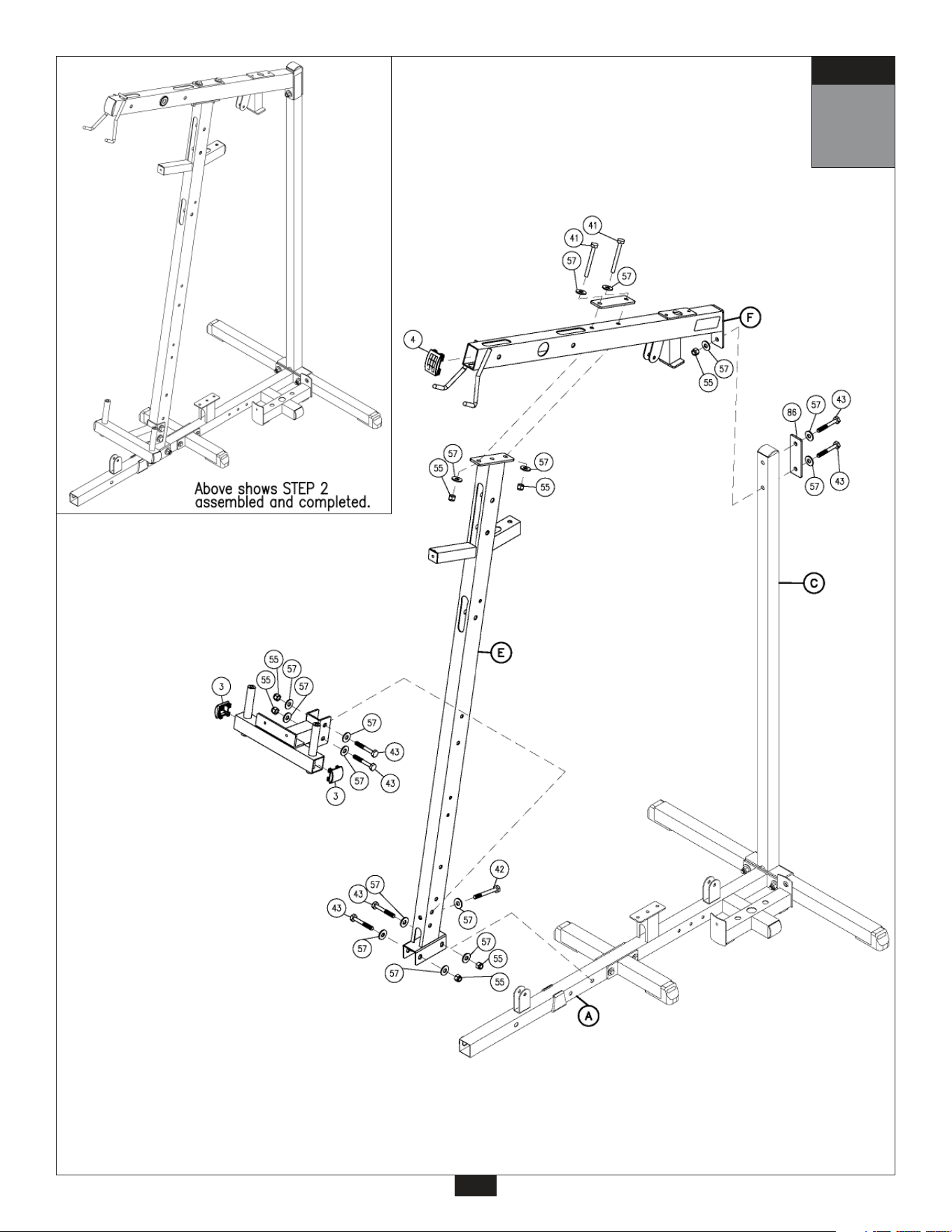
Be careful to assemble all components
in the sequence they are presented.
mm
Inch
A. Attach Angled Support Frame (E) to Main Base Frame (A) using:
Two 43 (1/2” x 3 1/4” hex head bolt)
Four 57 (1/2” washer)
Two 55 (1/2” nylon lock nut)
B. Insert Convex End Cap (4) to the front of the Top Frame (F).
Attach Top Frame (F) and Plate (86) to the Rear Vertical Frame (C) using:
Two 43 (1/2” x 3 1/4” hex head bolt)*
Three 57 (1/2” washer)
One 55 (1/2” nylon lock nut)
*NOTE:
The top bolt (43) goes into an internally threaded nut inside the Top Frame (F).
C. Attach Top Frame (F) and Plate (86) to Angled Support Frame (E) using:
Two 41 (1/2” x 4 1/4” hex head bolt)
Four 57 (1/2” washer)
Two 55 (1/2” nylon lock nut)
D. Attach Pec Dec Frame (G) to Angled Support Frame (E) in the bottom two holes as shown using:
One 42 (1/2” x 3 3/4” hex head bolt)
Two 43 (1/2” x 3 1/4” hex head bolt)
Five 57 (1/2” washer)
Two 55 (1/2” nylon lock nut)
Attach two Curved End Caps (3) to Pec Dec Frame (G) as shown.
4
NOTE:
Finger tighten all hardware in this step. Do Not wrench tighten until end of step 7.
STEP
2
STEP
5
Be careful to assemble all components
in the sequence they are presented.
mm
Inch
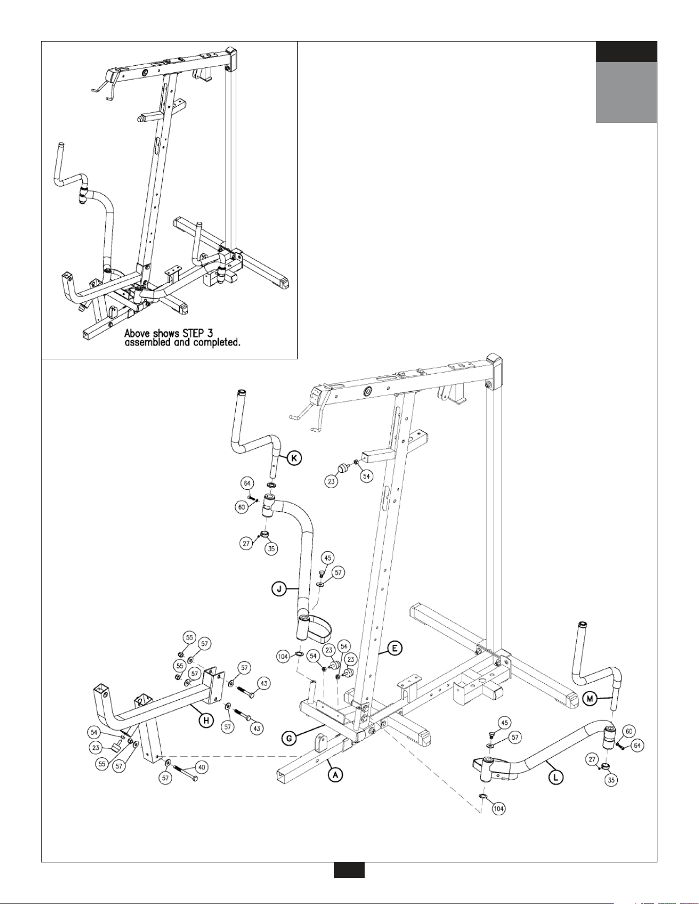
3
A. Above the Pec Dec Frame (G) connect the Leg Extension Frame (H) to Angled Support
Frame (E) using:
Two 43 (1/2” x 3 1/4” hex head bolt)
Four 57 (1/2” washer)
Two 55 (1/2” nylon lock nut)
B. Attach the Leg Extension Frame (H) to Main Base Frame (A) using:
One 40 (1/2” x 5 1/2” hex head bolt)
Two 57 (1/2” washer)
One 55 (1/2” nylon lock nut)
C. Attach Left Pec Dec Arm (J) to Pec Dec Frame (G) using:
One 45 (1/2” x 3/4” hex head bolt)
One 57 (1/2” washer)
Attach Left Pec Dec Handle (K) to Left Pec Dec Arm (J) using:
One 64 (5/16” x 3/4” round allen head bolt)
One 60 (5/16” spring lock washer)
D. Attach Right Pec Dec Arm (L) to Pec Dec Frame (G) using:
One 45 (1/2” x 3/4” hex head bolt)
One 57 (1/2” washer)
Attach Right Pec Dec Handle (M) to Right Pec Dec Arm (L):
One 64 (5/16” x 3/4” hex head bolt)
One 60 (5/16” spring lock washer)
E. Attach two Chrome Round End Cap (34) to the top of the Left Pec Dec Handle (K) and one to the
top of the Right Pec Dec Handle (M) as shown, and tighten Allen Screw (67).
Attach two Chrome Collars (35) one to the bottom of the Left Pec Dec Handle (K) and one to the
bottom of the Right Pec Dec Handle (M) as shown, and tighten Allen Screw (27).
F. Attach one Rubber Stop (23) to the front of Leg Extension Frame (H).
Attach two Rubber Stops (23) to the Pec Dec Frame (G).
Attach one Rubber Stop (23) to the horizontal pillar sticking out of the Angled Support Frame (E)
as shown.
6
NOTE:
Finger tighten all hardware in this step. Do Not wrench tighten until end of step 7.
STEP
3
STEP
7

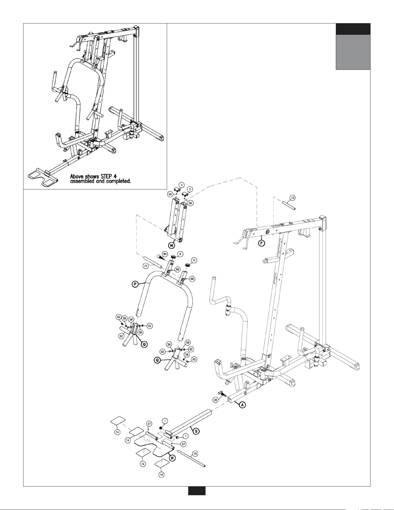
4
Be careful to assemble all components
in the sequence they are presented.
mm
Inch
A. Attach two Convex End Caps (3) to the top of Seated Press Arm Support (N).
Attach Seated Press Arm Support (N) to Top Frame (F) using Shaft (73), and tighten
Allen Screw (66).
B. Attach Seated Press Arm (P) to Seated Press Arm Support (N) using Shaft (74), and tighten
Allen Screw (66).
Attach two 1” X 2” Convex End Caps (6) to the top of the Seated Press Arm (P).
C. Attach two Seated Press Handles (Q) to Seated Press Arm (P) using:
Six 62 (3/8” x 5/8” flat allen head bolt)
Six 92 (3/8” bent lock washer)
Foam Grip (83) and Round End Cap (16) are preinstalled.
D. Attach Foot Plate (R) to Adjustable Chrome Frame (S) with Shaft (76) and tighten Allen Screw (27).
E. Slide Adjustable Chrome Frame (S) into Main Base Frame (A) and hold in place with T-Shaped
Pop Pin (26).
Slide two Round End Caps (7) into the openings on the top of the Adjustable Chrome Frame (S)
as shown.
8
NOTE:
Finger tighten all hardware in this step. Do Not wrench tighten until end of step 7.
STEP
4
9
STEP
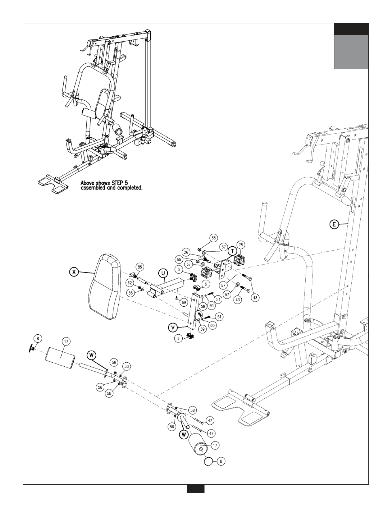
5
Be careful to assemble all components
in the sequence they are presented.
mm
Inch
A. Slide two Plastic Bushings (78) into Back Pad Holder (T) as shown.
Attach Back Pad Holder (T) To Angled Support Frame (E) using:
Two 43 (1/2” x 3 1/4” hex head bolt)
Four 57 (1/2” washer)
Two 55 (1/2” nylon lock nut)
B. Slide Convex End Cap (3) into Chrome Back Pad Frame (U) as shown.
Slide Chrome Back Pad Frame (U) into Back Pad Holder (T) and hold in place with
T-Shaped Pop Pin (26).
C. Slide two 1” X 2” Convex End Caps (6) into Back Pad Frame (V) as shown.
Attach Back Pad Frame (V) to Chrome Back Pad Frame (U) as shown with a T-Shaped
Pop Pin (85), and using:
One 62 (3/8” x 5/8” allen bolt)
One 58 (3/8” washer)
D. Attach two Leg Hold Downs (W) to the Angled Support Frame (E) using:
Two 53 (3/8” x 3 1/4” hex head bolt)
Four 58 (3/8” washer)
Two 56 (3/8” nylon lock nut)
C. Attach two Foam Rollers (17) onto Leg Hold Downs (W) and hold in place with two Roller End
Caps (8) as shown.
F. Attach Back Pad (X) to Back Pad Frame (V) using:
Two 51 (5/16” x 1 3/4” hex head bolt)
Two 60 (5/16” spring lock washer)
Two 59 (5/16” washer)
G. Insert Flat Allen Head Bolt (69) into Chrome Back Pad Frame (U), this will help hold the Chrome
Back Pad Frame (U) in place.
10
NOTE:
Finger tighten all hardware in this step. Do Not wrench tighten until end of step 7.
STEP
5
11
STEP

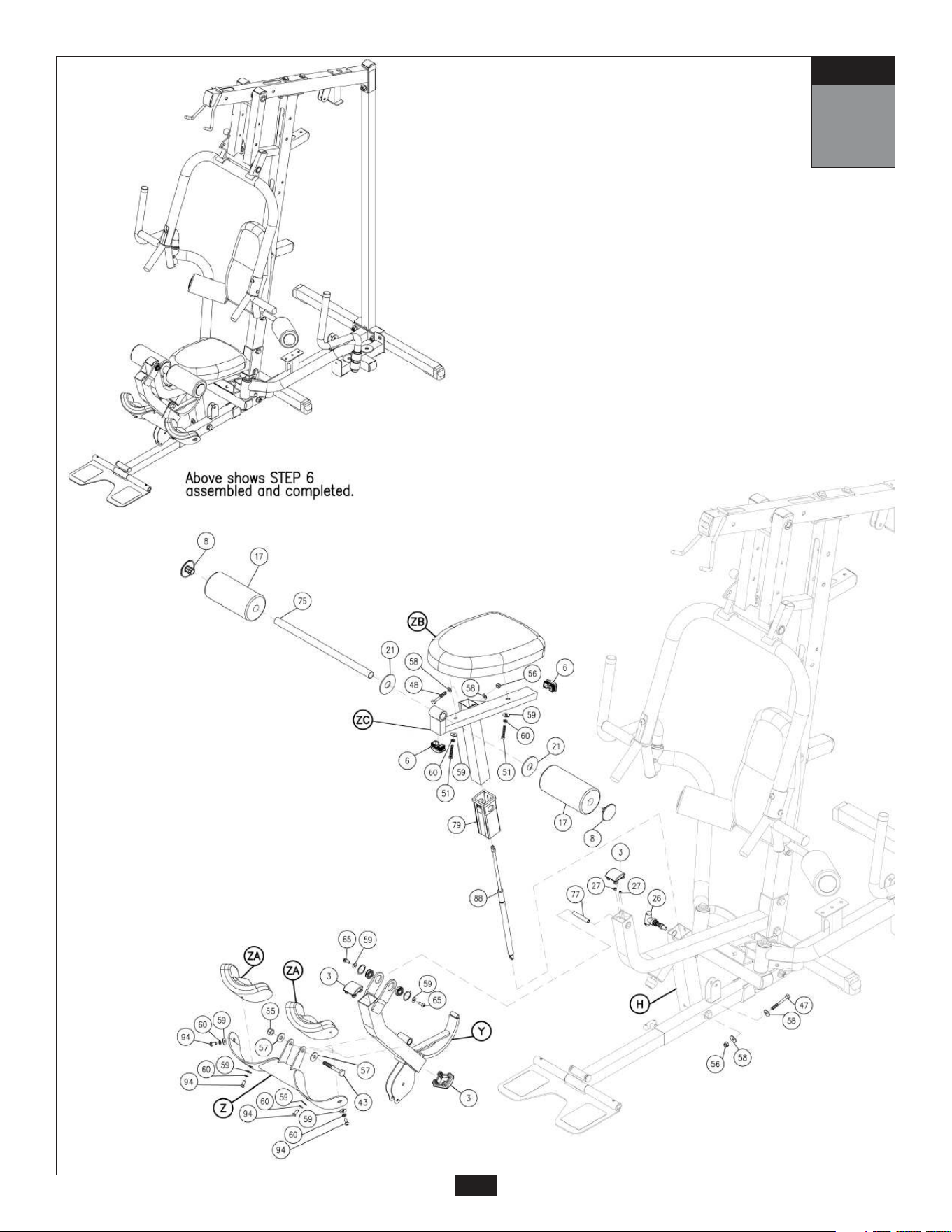
6
Be careful to assemble all components
in the sequence they are presented.
mm
Inch
A. Attach two Convex End Caps (3), one to the top and one to the bottom, of Leg Extension Arm (Y).
Attach Leg Extension Arm (Y) to Leg Extension Frame (H) using pre-installed Shaft (77) as
shown. Tighten the two Allen Screws (27) to lock down Shaft (77) in Leg Extension Frame (H).
Attach Convex End Cap (3) to the front of Leg Extension Frame (H) as shown.
B. Attach Leg Extension Pad Holder (Z) to Leg Extension Arm (Y) using:
One 43 (1/2” x 3 1/4” hex head bolt)
Two 57 (1/2” washer)
One 55 (1/2” nylon lock nut)
C. Attach the two Leg Pads (ZA) to Leg Extension Pad Holder (Z) using:
Four 94 (5/16” x 3/4” hex head bolt)
Four 60 (5/16” spring lock washer)
Four 59 (5/16” washer)
D. Attach two 1” X 2” Curved End Caps (6) to the front and back of the Leg Extension Seat Pad
Frame (ZC) as shown.
Attach Leg Extension Seat Pad (ZB) to Leg Extension Seat Pad Frame (ZC) using:
Two 51 (5/16” x 1 3/4” hex head bolt)
Two 60 (5/16” spring lock washer)
Two 59 (5/16” washer)
E. Slide Plastic Bushing (79) into Leg Extension Frame (H) as shown.
Attach Hydraulic Seat Adjuster (88) to the bottom and inside the receptacle in the Leg Extension
Frame (H) using:
One 47 (3/8” x 3” hex head bolt)
Two 58 (3/8” washer)
One 56 (3/8” nylon lock nut)
F. Slide Leg Extension Seat Pad Frame (ZC) into Plastic Bushing (79) in Leg Extension Frame (H)
and attach to the top of Hydraulic Seat Adjuster (88) using:
One 48 (3/8” x 2 3/4”hex head bolt)
Two 58 (3/8” washer)
One 56 (3/8” nylon lock nut)
Insert T-Shaped Pop Pin (26) into the threaded opening in the Leg Extension Frame (H).
G. Attach Foam Roller Bar (75) to the front of the Leg Extension Seat Pad Frame (ZC) as shown.
Slide Foam Rollers (17) onto Foam Roller Bar (75). Hold in place with 3” Plastic Washer (21), on
the inside, and Roller End Caps (8) on the outside.
12
NOTE:
Finger tighten all hardware in this step. Do Not wrench tighten until end of step 7.
STEP
6
13
STEP
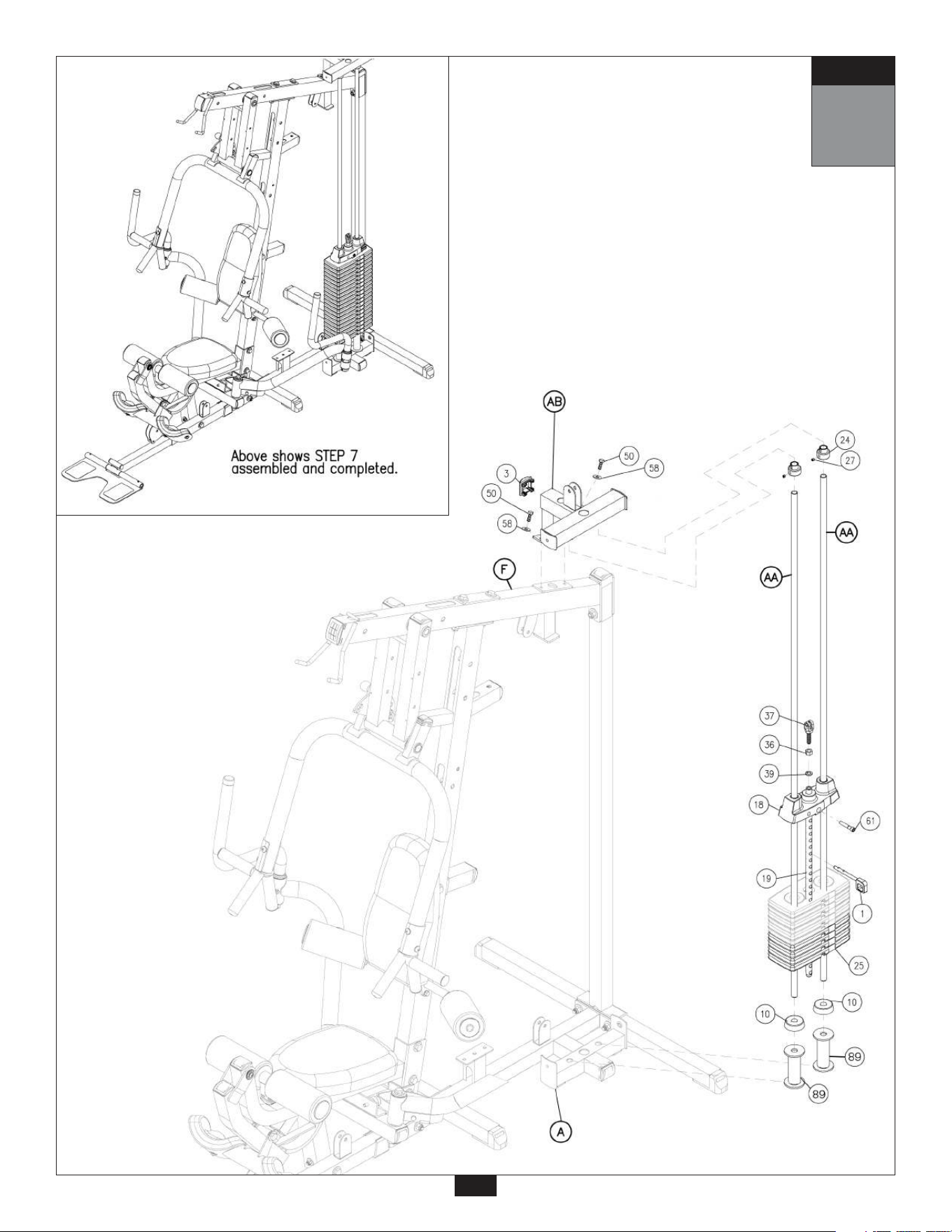
7
Be careful to assemble all components
in the sequence they are presented.
mm
Inch
A. Place two Weight Stack Risers (89) and two Rubber Donuts (10) onto Main Base Frame (A) as
shown. Slide two Guide Rods (AA) through the Rubber Donuts (10), through the two Weight Stack
Risers (89), and into the Main Base Frame (A).
B. Slide Weight Stack Plates (25) onto Guide Rods (AA). Make sure the opening in each Weight
Stack Plate (25), for the Weight Stack Pin (1), is facing outwar
d.
C. Connect Top Plate (18) to the Selector Rod (19) using:
One 61 (3/8” X 1 1/2” round allen head)
Slide Top Plate (18) and Selector Rod (19) onto Guide Rods (AA).
D. Slide two Shaft Collars (24) onto the two Guide Rods (AA) as shown.
E. Insert Guide Rods (AA) into Top Weight Stack Frame (AB), and Attach Top Weight Stack
Frame (AB) to Top Frame (F) using:
Two 50 (3/8” x 1” hex head bolt)
Two 58 (3/8” washer)
Attach Curved End Cap (3) to Top Weight Stack Frame (AB) as shown.
F. Slide Shaft Collars (24) up into the Top Weight Stack Frame (AB) and turn the Shaft Collar, so the
Shaft Collars (24) lock onto the Top Weight Stack Frame (AB), Now tighten each Allen Screw (27)
in Shaft Collars (24).
G. At this point you can now wrench tighten all bolts and nuts on the main frame unit.
14
STEP
7
15
STEP

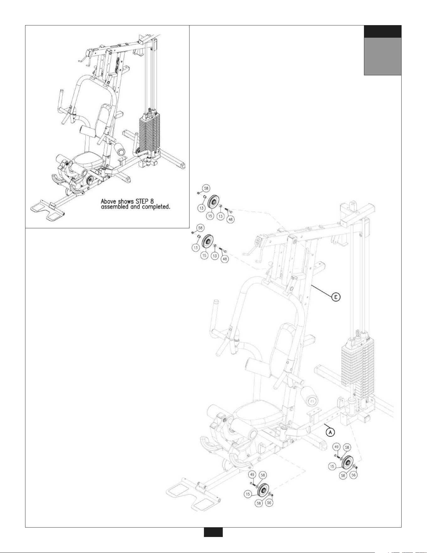
8
Be careful to assemble all components
in the sequence they are presented.
STEP
mm
Inch
A. Insert two Pulleys (15) into Angled Support Frame (E) as shown using:
Two 48 (3/8” x 2 3/4” hex head bolt)
Four 13 (pulley spacer)
Two 56 (3/8” nylon lock nut)
B. Install two Pulleys (15) onto Main Base Frame (A) as shown using:
Two 49 (3/8” x 1 3/4” hex head bolt)
Four 58 (3/8” washer)
Two 56 (3/8” nylon lock nut)
NOTE:
Leave all hardware finger tight. Do not wrench tighten hardware until after the final
cable adjustments are complete in Step 18.
16
8
STEP
17
9
Be careful to assemble all components
in the sequence they are presented.
STEP
mm
Inch
18
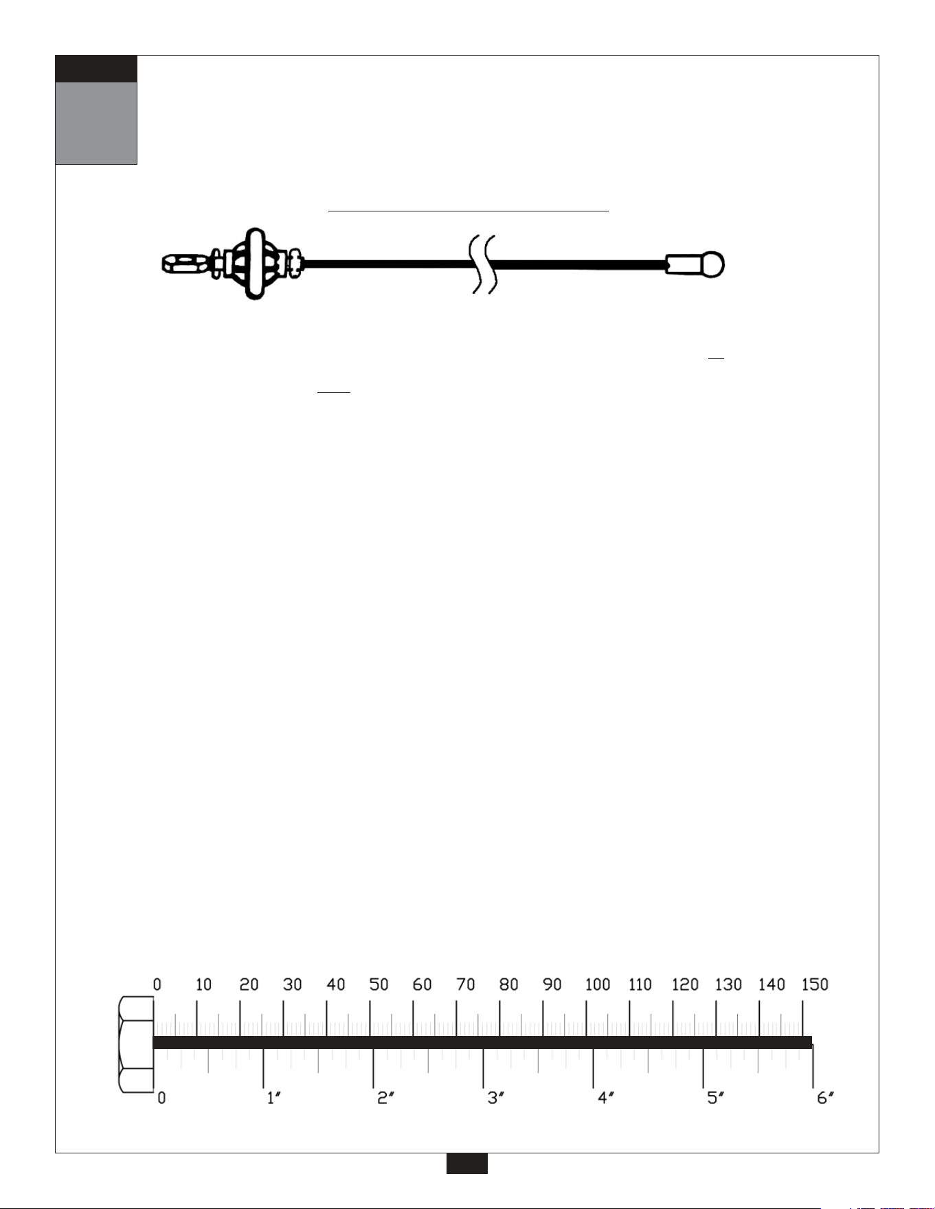
Lat Pulldown Cable (96)
Ball Stop End Metal Ball End
4955 mm
16’ 3”
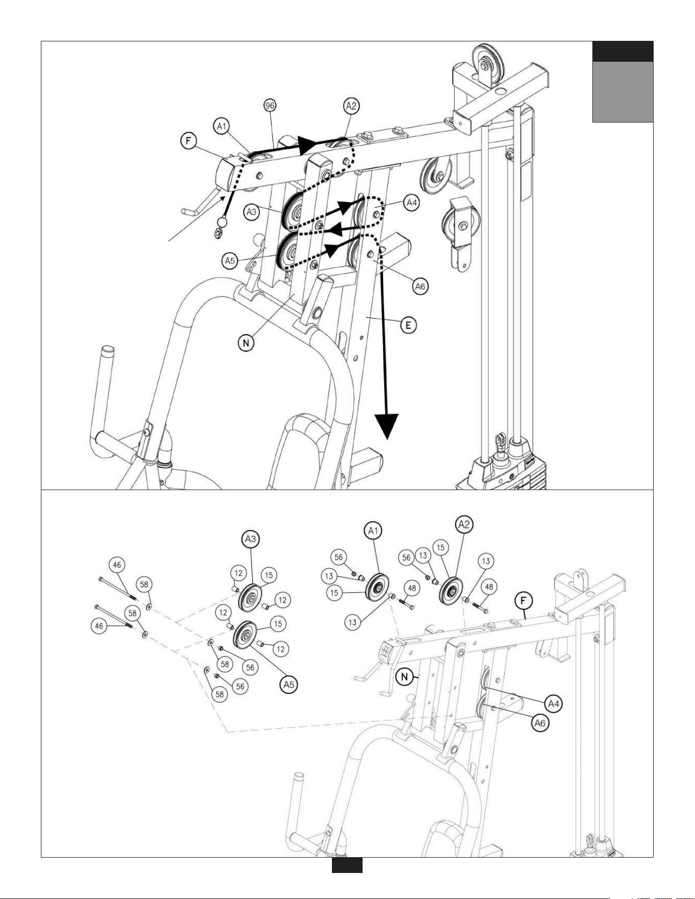
A. See diagram 1. Begin at the high pulley station. Route the Lat Pulldown Cable (96) up
through the first
opening where pulley (A1) will be installed, and out through the top. Route Cable (96) above the Top
Frame (F) and then down through the second opening where pulley (A2) will be installed. Pull the
entire length of cable through.
B. See diagram 2. Insert two Pulleys (15), Pulleys (A1) and (A2), into Top Frame (F) under Cable (96)
and attach using for each pulley:
One 48 (3/8” x 2 3/4” hex head bolt)
Two 13 (pulley spacer)
One 56 (3/8” nylon lock nut)
C. Route Cable (96) around Pulley (A3) as shown in diagram 1 and attach Pulley (A3) to Seated Press
Arm Support (N) as shown in diagram 2 using:
One 46 (3/8” x 7 1/2” hex head bolt)
Two 12 (metal spacer)
One 56 (3/8” nylon lock nut)
D. See diagram 1. Feed Cable (96) above Pulley (A4) -already installed. Route Cable (96) around
Pulley (A4) and feed back between Pulley (A4) and Pulley (A6) -already installed.
E. Route Cable (96) around Pulley (A5) as shown in diagram 1 and attach Pulley (A5) to Seated Press
Arm Support (N) as shown in diagram 2 using:
One 46 (3/8” x 7 1/2” hex head bolt)
Two 12 (metal spacer)
One 56 (3/8” nylon lock nut)
F. See diagram 1. Feed Cable (96) back between Pulley (A4) and Pulley (A6) -already installed. Pull
entire length of Cable (96) through, and feed down through the hole in the small arm sticking out of
Angled Support Frame (E).
9
STEP
19
Start here at high pulley
station by inserting the
metal ball end here.
Lat Pulldown
Cable
Diagram 1
Cable Installation
Diagram 2
Pulley Installation
10
Be careful to assemble all components
in the sequence they are presented.
STEP
mm
Inch
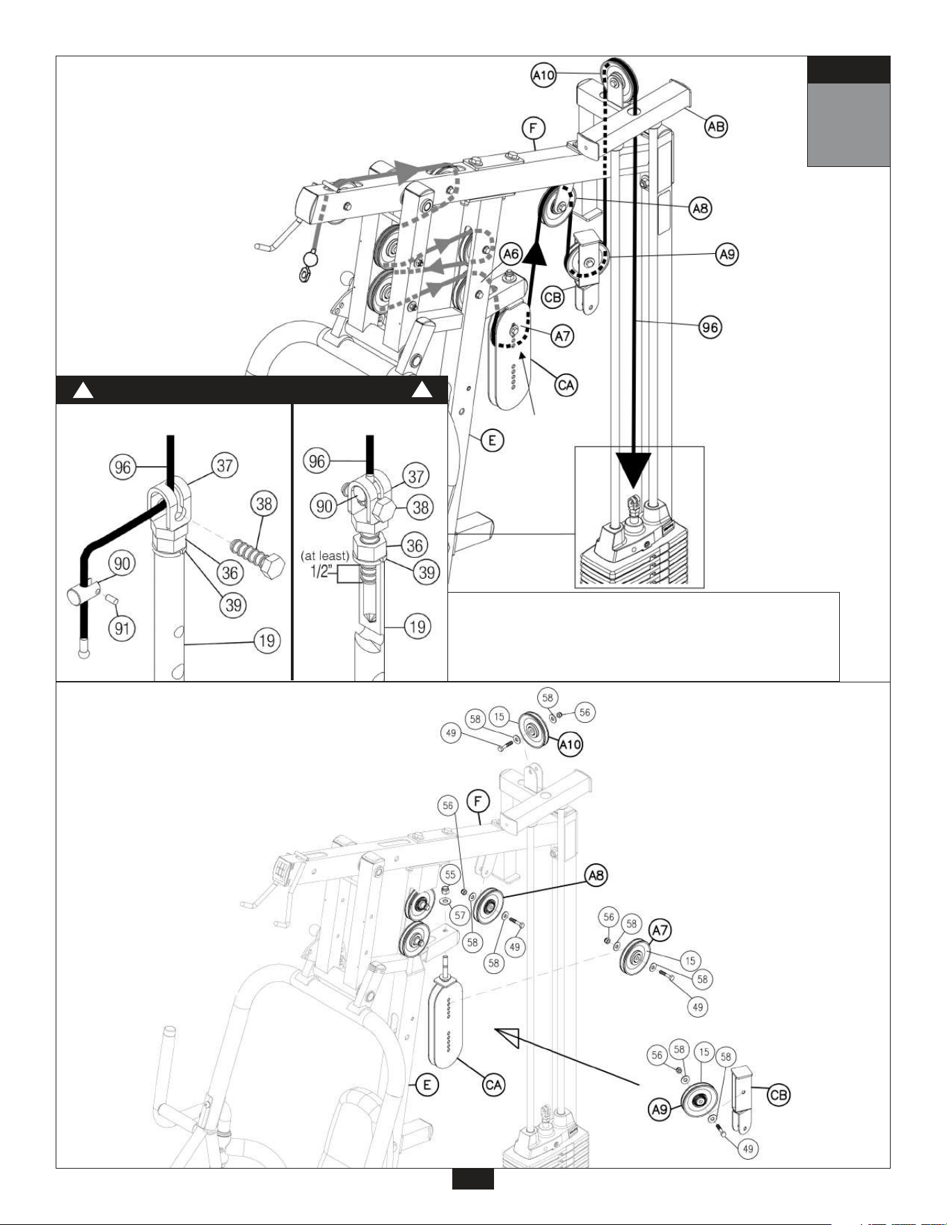
20
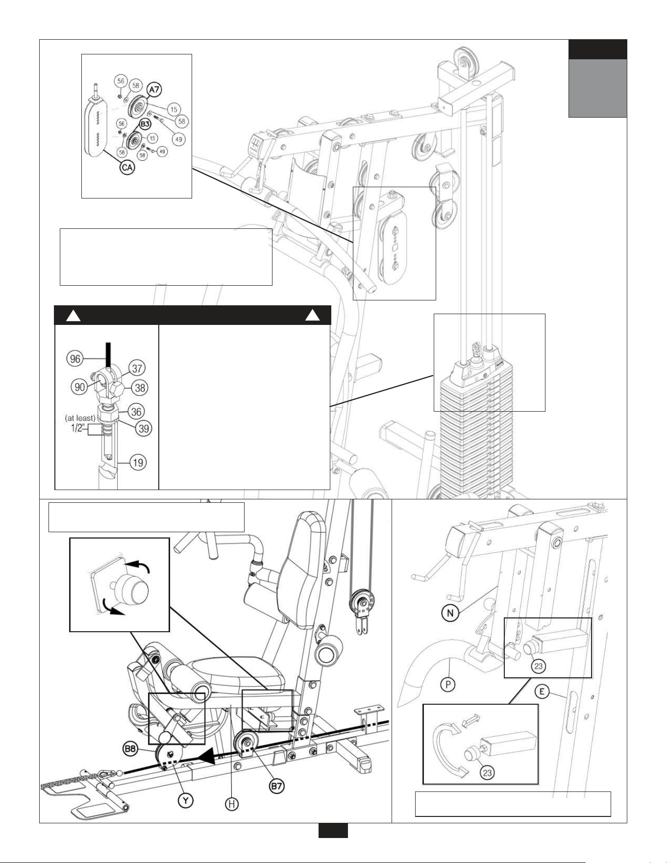
A. See diagram 2. Attach Double Adjustable Pulley Holder (CA) to the small arm sticking out of the
Angled Support Frame (E) as shown using:
One 57 (1/2” washer)
One 55 (1/2” nylon lock nut)
B. Install Pulley (A7) into Double Adjustable Pulley Holder (CA), install into the third hole from the
top, as shown in diagram 2 using:
One 49 (3/8” x 1 3/4” hex head bolt)*
Two 58 (3/8” washer)
One 56 (3/8” nylon lock nut)
See diagram 1. Route Cable (96) through Double Adjustable Pulley Holder (CA) and under
Pulley (A7).
*NOTE:
Leave Pulley (A7) finger tight, until after final cable adjustments in Step 15.
C. See diagram 1. Route Cable (96) through the flange hanging from Top Frame (F) and hold in
place with Pulley (A8). Install Pulley (A8) as shown in diagram 2 using:
One 49 (3/8” x 1 3/4” hex head bolt)
Two 58 (3/8” washer)
One 56 (3/8” nylon lock nut)
D. Route Cable (96) through the top of 45 Degree Double Pulley Holder (CB) and hold in place with
Pulley (A9) as shown in diagram 2 using:
One 49 (3/8” x 1 3/4” hex head bolt)
Two 58 (3/8” washer)
One 56 (3/8” nylon lock nut)
E. See diagram 2. Install Pulley (A10) to the flange above the Top Weight Stack Frame (AB) using:
One 49 (3/8” x 1 3/4” hex head bolt)
Two 58 (3/8” washer)
One 56 (3/8” nylon lock nut)
F. See diagram 1. Route Cable (96) up through the Top Weight Stack Frame (AB) above
Pulley (A10), and down through Top Weight Stack Frame (AB) toward weight stack.
G. See diagram 1A. Remove Hex Head Bolt (38) from Selector Rod Top Bolt (37), slide Cable (96)
through Selector Rod Top Bolt (37) and out through the side. Attach Cable End Shaft (90) and
tighten Allen Screw (91). Pull Cable (96) tight, so Cable End Shaft (90) fits inside Selector Rod
Top Bolt (37). Reinstall Hex Head Bolt (38) in Selector Rod Top Bolt (37).
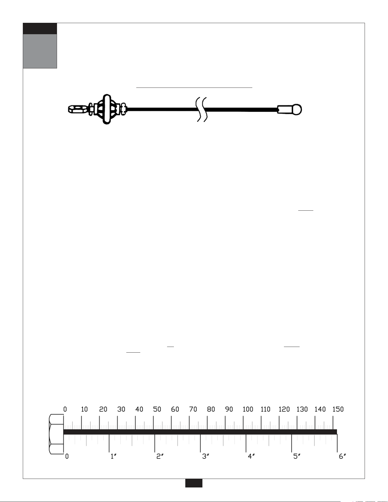
Ball Stop End
Metal Ball End
4955 mm
16’ 3”
Lat Pulldown Cable (96)
WARNING
!
!
Diagram 1A
21
10
STEP
Selector Rod Top Bolt (37) must be threaded a minimum of
1/2” into the Selector Rod (19), and Jam Nut (36) tightened
securely against spring lock washer (39) to ensure proper
connection. Check the Jam Nut (36) once a week to make
sure it is tight.
Start here
by routing
the cable
around
pulley A7.
Lat Pulldown
Cable
Diagram 1
Cable Installation
Diagram 2
Pulley Installation
11
Be careful to assemble all components
in the sequence they are presented.
STEP
mm
Inch
A. See diagram 1. Insert either end of Ab Crunch Cable (97) into the opening in Angled Support
Frame (E), above Back Pad (X), and pull entire length of cable through.
B. Install Pulley (B1) into Angled Support Frame (E) under Cable (97) as shown in diagram 2 using:
One 48 (3/8” x 2 3/4” hex head bolt)
Two 13 (pulley spacer)
One 56 (3/8” nylon lock nut)
C. See diagram 1. Route Cable (97) through the top of the 90 Degree Double Pulley Holder (CC)
and hold Cable (97) in place with Pulley (B2) using:
One 49 (3/8” x 1 3/4” hex head bolt)
Two 58 (3/8” washer)
One 56 (3/8” nylon lock nut)
D. See diagram 1. Route Cable (97) through the bottom of the Double Adjustable Pulley Holder (CA).
Insert Pulley (B3) into the Double Pulley Holder (CA) and install into the third hole from the bottom
as shown in diagram 2 using:
One 49 (3/8” x 1 3/4” hex head bolt)*
Two 58 (3/8” washer)
One 56 (3/8” nylon lock nut)
*NOTE:
Leave Pulley (B3) finger tight, until after final cable adjustments in Step 15.
22
Ball Stop End Ball Stop End
5185mm
17’ 1”
Ab Cr
unch Cable (97)
23
11
STEP
Start here
Ab
Crunch
Cable
by inserting
either end
of cable.
Diagram 1
Cable Installation
Diagram 2
Pulley Installation
12
STEP
Be careful to assemble all components
in the sequence they are presented.
Ball Stop End
Ball Stop End
5185mm
17’ 1”
Ab Cr
unch Cable (97)
mm
Inch
24
757mm
2’ 5”
Stamped Eye
Stamped Eye
Shor
t Cable (99)
A. See diagram 1. Route Cable (97) through Pulley Holder with Hook (CD) and hold Cable (97) in place
with Pulley (B4) as shown in diagram 2 using:
One 49 (3/8” x 1 3/4” hex head bolt)
Two 58 (3/8” washer)
One 56 (3/8” nylon lock nut)
NOTE:
If you are not
installing the Leg Press, then connect Short Cable (99) to the bottom of
Pulley Holder With Hook (CD) and to Main Frame (A). See Cable 99 diagram .
B. See diagram 1. Route Cable (97) through the bottom of the 45 Degree Double Pulley Holder (CB) and
hold Cable (97) in place with Pulley (B5) as shown in diagram 2 using:
One 49 (3/8” x 1 3/4” hex head bolt)
Two 58 (3/8” washer)
One 56 (3/8” nylon lock nut)
C. See diagram 1. Route Cable (97) under Pulley (B6) -preinstalled. Route Cable (97) forward towards the
front of the gym.
Insert Cable (97) through small pillar in Main Frame (A), then through Angled Support Frame (E),
and under Pulley (B7) -preinstalled.
D. See diagram 1. Route Cable (97) through pulley holder at the end of the Leg Extension Arm (Y).
Install Pulley (B8) as shown in diagram 2 using:
One 49 (3/8” x 1 3/4” hex head bolt)
Two 58 (3/8” washer)
One 56 (3/8” nylon lock nut)
Install hex head bolt (49) into the end of the Leg Extension Arm (Y) to hold Cable (97) in place as
shown in diagram 2.
25
12
STEP
Ab Crunch
Cable
Start here and route
cable around pulley B4.
Cable 99
Diagram
Short Cable
Diagram 1
Cable Installation
Diagram 2
Pulley Installation
Be careful to assemble all components
in the sequence they are presented.
mm
Inch
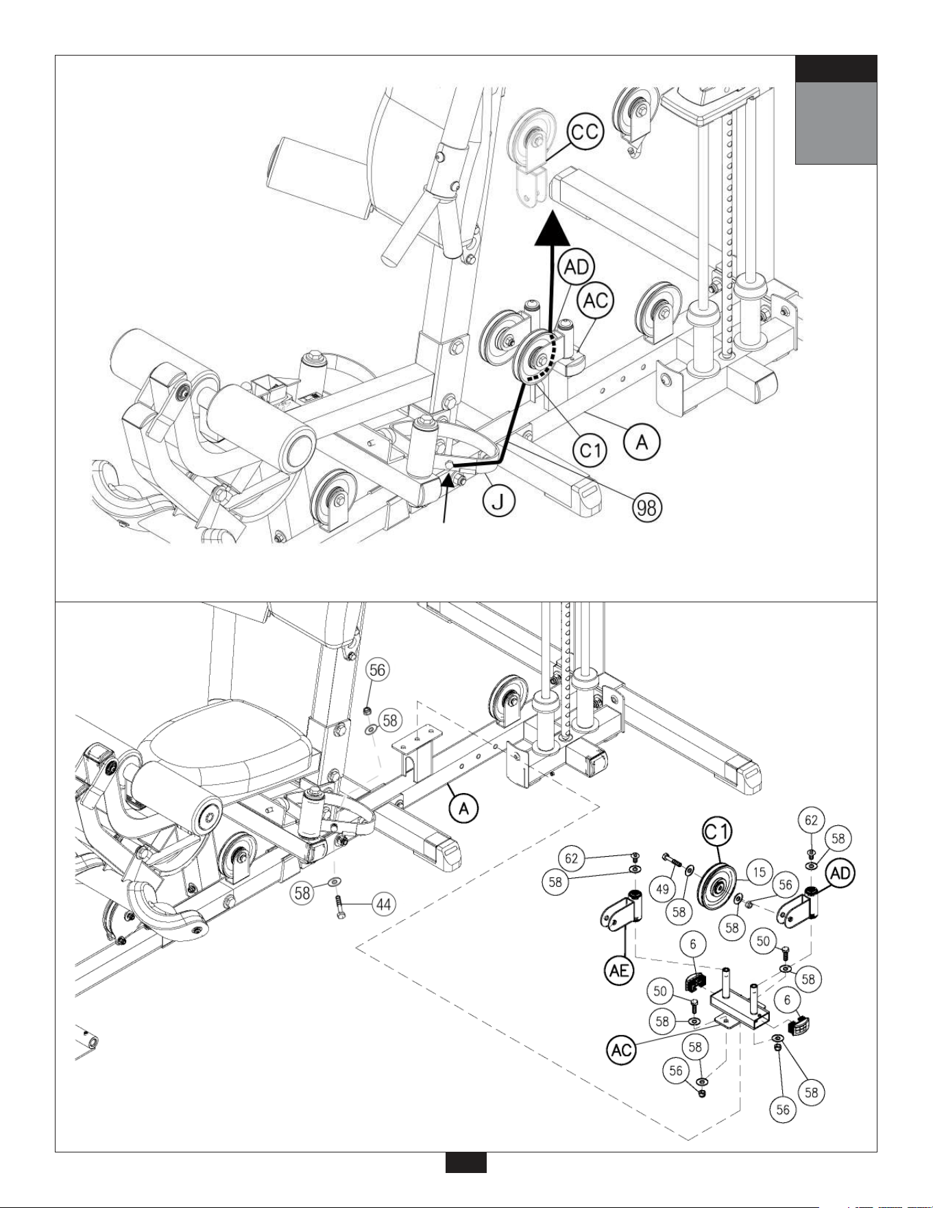
A. See diagram 2. Attach Pec Dec Pulley Frame (AC) to Main Frame (A) using:
Two 50 (3/8” x 1” hex head bolt)
Four 58 (3/8” washer)
Two 56 (3/8” nylon lock nut)
B. See diagram 2. Attach two End Caps (6) to either end of Pec Dec Pulley Frame (AC).
Attach Left Pec Dec Pulley Holder (AD) to Pec Dec Pulley Frame (AC) using:
One 62 (3/8” x 5/8” allen bolt)
One 58 (3/8” washer)
Attach Right Pec Dec Pulley Holder (AE) to Pec Dec Pulley Frame (AC) using:
One 62 (3/8” x 5/8” allen bolt)
One 58 (3/8” washer)
C. Bolt Pec Dec Cable (98) to cam on Left Pec Dec Arm (J) as shown in diagram 1 using:
One 44 (3/8” x 3/4” hex head bolt)
Two 57 (3/8” washer)
One 55 (3/8” nylon lock nut)
D. See diagram 1. Route Cable (98) through Left Pec Dec Pulley Holder (AD), hold cable in place
with Pulley (C1) using:
One 49 (3/8” x 1 3/4” hex head bolt)
Two 58 (3/8” washer)
One 56 (3/8” nylon lock nut)
13
STEP
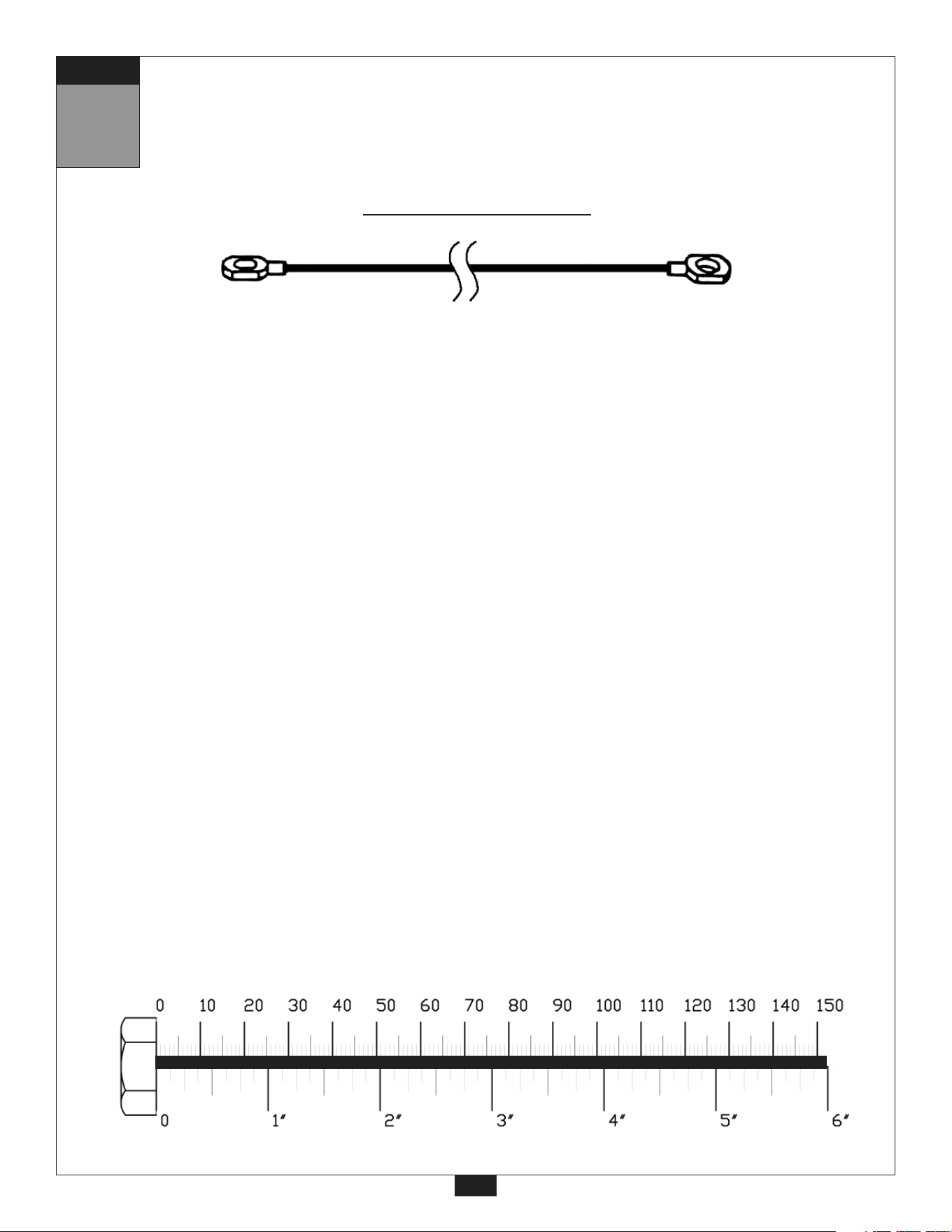
Pec Dec Cable (98)
Stamped Eye EndStamped Eye End
2020mm
6’ 7.5”
26
27
13
STEP
Start routing cable here
by bolting cable to Left
Pec Dec Arm (J).
Pec Dec Cable
Diagram 1
Cable Installation
Diagram 2
Pulley Installation
14
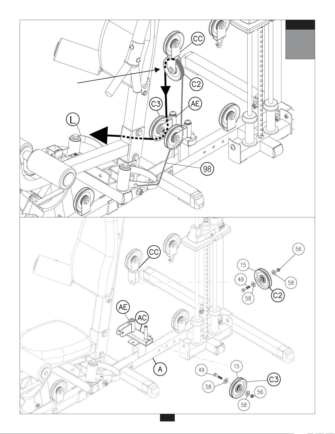
STEP
A. See diagram 1. Route Cable (98) up and into 90 Degree Double Pulley Holder (CC) and install
Pulley (C2) using:
One 49 (3/8” x 1 3/4” hex head bolt)
Two 58 (3/8” washer)
One 56 (3/8” nylon lock nut)
B. Insert Cable (98) into Right Pec Dec Pulley Holder (AE) hold cable in place by installing
Pulley (C3) as shown in diagram 2 using:
One 49 (3/8” x 1 3/4” hex head bolt)
Two 58 (3/8” washer)
One 56 (3/8” nylon lock nut)
C. Attach Cable (98) to cam on Right Pec Dec Arm (L) using:
One 44 (3/8” x 3/4” hex head bolt)
Two 57 (3/8” washer)
One 55 (3/8” nylon lock nut)
Be careful to assemble all components
in the sequence they are presented.
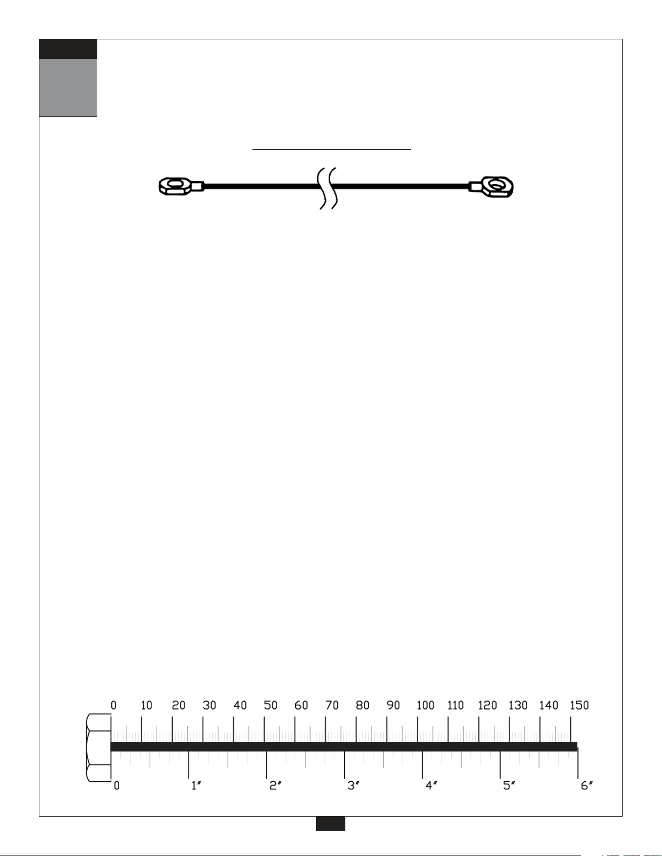
Pec Dec Cable (98)
mm
Inch
28
Stamped Eye End
Stamped Eye End
2020mm
6’ 7.5”
29
14
STEP
Start here by routing
cable around pulley C2.
Pec Dec Cable
Diagram 1
Cable Installation
Diagram 2
Pulley Installation
Be careful to assemble all components
in the sequence they are presented.
Inch
NOW IS THE TIME TO MAKE ALL NECESSAR
Y
CABLE ADJUSTMENTS
After cable installation is complete you must check all cables for proper tension. Obvious signs that
cable tension problems exist include:
c Top Plate (18) does not rest directly on the top Weight Stack Plate (25).
c The holes in the Selector Bar (19) do not line up with holes in the Weight Stack Plates (25).
c Cable(s) are sloppy and there is no resistance from the weight stack for the first few
inches of the exercise.
There are SEVEN areas for cable adjustment on the G5S:
A. Selector Rod Top Bolt (37).*
B. TWO adjustments in Double Adjustable Pulley Holder (CA).
C. FOUR Rubber Stops (23).
*SEE NOTE 1 ON PAGE 39
If there is to much tension, and the Top Plate (18) is not resting directly on the top weight stack plate:
1st. -Move pulley (A7) up, or Pulley (B3) down in the Double Adjustable Pulley Holder (CA).
2nd. -Turn and tighten one of the Rubber Stops (23).
If there is to much play or excessive slack:
1st. -Turn and loosen the Rubber Stop (23).
2nd. -Move Pulley (A7) down, or Pulley (B3) up in the Double Adjustable Pulley Holder (CA).
3rd. -Screw the Selector Rod Top Bolt (37) farther into the Selector Rod (19).
NOTE:
Cables should be inspected daily and adjusted periodically to ensure safe and
smooth operation.
NOTE:
After cable adjustment is complete, go back and tighten two bolts holding pulleys
in pulley housing on Double Adjustable Pulley Holder (CA).
30
15
mm
STEP
31
15
STEP
Selector Rod Top Bolt (37)
must be threaded a
minimum of 1/2” into the
Selector Rod (19), and
Jam Nut (36) tightened
securely against spring
lock washer (39) to ensure
proper connection.
WARNING
!
!
NOTE 1
Check Jam Nut (36) weekly to be sure it is
tight and locked onto the Selector Rod (19).
(See page 49)
Turn and loosen Rubber Stop (23) to take
up space and tighten cable.
Loosen
Turn and loosen Rubber Stop (23) to take
up space and tighten cable.
B.
A.
C.
C.
Be careful to assemble all components
in the sequence they are presented.
mm
Inch
SEE NOTE 1 ON PAGE 41:
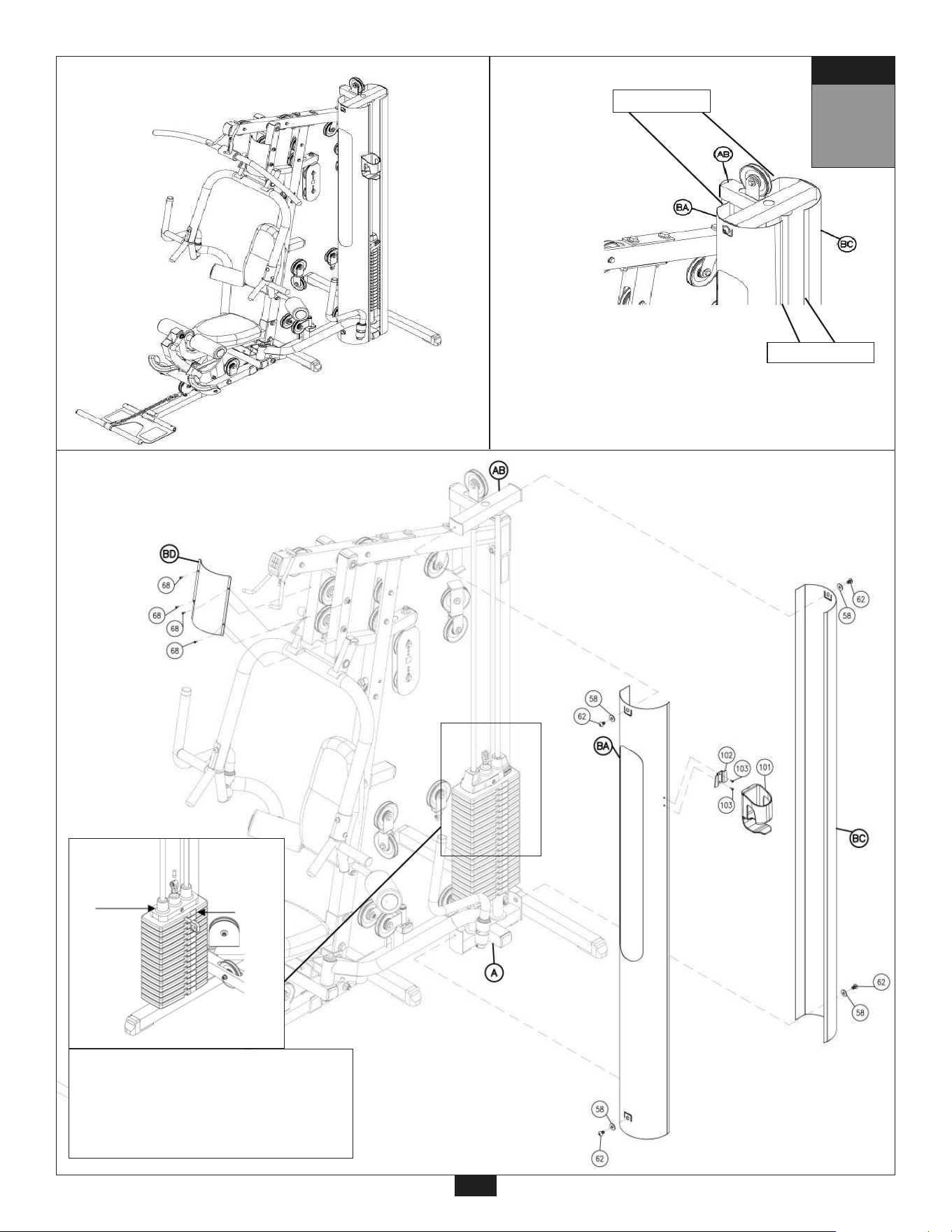
A. Apply weight stack numbers to weight stack Top Plate (8) and each Weight Stack Plate
as shown.
SEE NOTE 2 ON PAGE 41:
B. Weight Stack Shroud (BA) is pre-assembled with Shroud Insert (BB).
Attach Weight Stack Shroud (BA) to the side of the weight stack as shown.
Bolt onto Main Base Frame (A) at the bottom and Top Weight Stack Frame (AB) using:
Two 62 (3/8” x 5/8” round allen head)
Two 58 (3/8” washer)
C. Attach Back Weight Stack Shroud (BC), to the back side of the weight stack, onto the Main Base
Frame (A) at the bottom and to the Top Weight Stack Frame (AB) as shown using:
Two 62 (3/8” x 5/8” round allen head)
Two 58 (3/8” washer)
D. Attach Press Arm Shroud (BD) to the Seated Press Arm Support (N) using:
Four 68 (1/8” x 5/8” round allen head)
E. Connect the Water Bottle Bracket (102) to the Weight Stack Shroud (BA) using:
Two 103 (1/8” x 3/8” screw)
F. Slide the Water Bottle Holder (101) onto the Water Bottle Bracket (102) as shown.
32
16
STEP
33
16
STEP
2” flat side
3/4” flat side
Above shows STEP 16
assembled and complete.
NOTE 2
This is the top view of the two Weight Stack Shrouds.
Note the shape of each shroud for proper placement.
Apply weight stack numbers to the Weight
Stack Plates (25). Start at the Top Plate (18)
with the number 1, and the first plate
should be number 2. The following Weight
Stack Plates (25) should be numbered in
sequential order down through the stack.
NOTE 1
#1
#2

G5S Parts List
KEY# QTY PART# DESCRIPTION
Part numbers are required when ordering parts.
A
B
C
D
E
F
G
H
J
K
L
M
N
P
Q
R
S
T
U
V
W
Y
Z
ZC
AA
AB
AC
AD
AE
1
1
1
2
1
1
1
1
1
1
1
1
1
1
2
1
1
1
1
1
2
1
1
1
2
1
1
1
1
G5SMBF-A
G5SRBF-B
G5SRVF-C
G5SSBF-D
G5SASF-E
G5STF-F
G5SPDF-G
G5SLEF-H
G5SLPDA-J
G5SLPDH-K
G5SRPDA-L
G5SRPDH-M
G5SSPAS-N
G5SSPA-P
G5SSPH-Q
G5SFP-R
G5SACF-S
G5SBPH-T
G5SCBPF-U
G5SBPF-V
G5SLHD-W
G5SLEA-Y
G5SLEPH-Z
G5SLESPF-ZC
G5SGR-AA
G5STWSF-AB
G5SPDPF-AC
G5SLPDPH-AD
G5SRPDPH-AE
MAIN BASE FRAME
REAR BASE FRAME
REAR VERTICAL FRAME
SIDE BASE FRAME
ANGLED SUPPORT FRAME
TOP FRAME
PEC DEC FRAME
LEG EXTENSION FRAME
LEFT PEC DEC ARM
LEFT PEC DEC HANDLE
RIGHT PEC DEC ARM
RIGHT PEC DEC HANDLE
SEATED PRESS ARM SUPPORT
SEATED PRESS ARM
SEATED PRESS HANDLES
FOOT PLATE
ADJUSTABLE CHROME FRAME
BACK PAD HOLDER
CHROME BACK PAD FRAME
BACK PAD FRAME
LEG HOLD DOWN
LEG EXTENSION ARM
LEG EXTENSION PAD HOLDER
LEG EXTENSION SEAT PAD FRAME
GUIDE RODS
TOP WEIGHT STACK FRAME
PEC DEC PULLEY FRAME
LEFT PEC DEC PULLEY HOLDER
RIGHT PEC DEC PULLEY HOLDER
34

G5S Hardware List
KEY# QTY PART# DESCRIPTION
Part numbers are required when ordering parts.
1
2
3
4
5
6
7
8
9
10
11
12
13
14
15
16
17
18
19
20
21
22
23
24
25
26
27
28
29
30
31
32
33
34
35
36
37
38
39
40
41
42
43
44
45
46
47
48
49
WEIGHT STACK PIN 4 1/4” X 7/16”
STEEL CHAIN 3/16”
CONVEX END CAP 2” X 2”
CONVEX END CAP 2” X 3”
ROUND END CAP 1 3/8”
CONVEX END CAP 1” X 2”
ROUND END CAP 1” OD X 5/16” L
ROLLER END CAP 1”
FOOT CAP 2” X 2”
RUBBER DONUT 2 1/2”
SNAP LINK
METAL SPACER 5/8” OD X 3/8” ID X 7/8” L
PULLEY SPACER 5/8” OD X 3/8” ID X 5/8” L
GRIP TAPE 5 1/2” X 3 3/4”
PLASTIC PULLEY 4 1/4” X 3/4” WIDE
ROUND END CAP 1 1/2”
FOAM ROLLER 3 1/2” X 8”
TOP PLATE (10 lbs.)
SELECTOR ROD (25 selector holes)
WEIGHT STACK SHIMS 2” X 2”
PLASTIC WASHER 3”
RUBBER PAD 1 1/2” X 1 3/4”
RUBBER STOP 1 1/2”
SHAFT COLLAR 1 3/8” OD X 3/4” ID 1.5” L
WEIGHT PLATE
T-SHAPED POP PIN 3” L
ALLEN SCREW 5/16” X 5/16” FULL THREAD
STEEL BUSHING 1 5/8“ OD 7/8” ID PREINSTALLED
STEEL BUSHING 1 5/8” OD 1” ID 5/8” L
OILITE BUSHING 1 5/8” OD 1” ID 5/8” L- PREINSTALLED
OILITE WASHER 1 1/2” OD 1” ID 1/16” L- PREINSTALLED
OILITE BUSHING 7/8” OD 9/16” ID 7/16” L- PREINSTALLED
OILITE BUSHING 3/4” OD 1/2” ID 3/8” L
CHROME ROUND END CAP 1 7/16” OD 1” ID 3/4” L
CHROME COLLAR 1 7/16” OD 1” ID 5/8” L
JAM NUT 1/2”
SELECTOR ROD TOP BOLT 1/2” X 2” FULL THREAD
HEX HEAD BOLT 3/8” X 7/8” FULL THREAD
SPRING LOCK WASHER 1/2”
HEX HEAD BOLT 1/2” X 5 1/4” PARTIAL THREAD
HEX HEAD BOLT 1/2” X 4 1/4” PARTIAL THREAD
HEX HEAD BOLT 1/2” X 4” PARTIAL THREAD
HEX HEAD BOLT 1/2” X 3 1/4” PARTIAL THREAD
HEX HEAD BOLT 3/8” X 3/4” FULL THREAD
HEX HEAD BOLT 1/2” X 3/4” FULL THREAD
HEX HEAD BOLT 3/8” X 7 1/4” PARTIAL THREAD
HEX HEAD BOLT 3/8” X 3” PARTIAL THREAD
HEX HEAD BOLT 3/8” X 2 3/4” PARTIAL THREAD
HEX HEAD BOLT 3/8” X 1 3/4” PARTIAL THREAD
1
1
11
1
4
8
2
4
4
2
5
4
10
4
21
6
4
1
1
2
2
1
4
2
25
3
10
2
2
8
2
4
2
2
2
1
1
1
1
1
2
1
12
2
2
2
3
5
15
35
JPIN4.25
JSCH.18
JCEC22
JCEC23
JREC1.37
JCEC12
JREC1X.31
JREC1
JFC22
JRD2.5
JSNAP3
JMS.62X.37
JPS.62X.37
JGT5.5
JPP4.5X.75
JREC1.5
JFOAM3.5x8
JTP10
JSR25
JWSS22
JPW3
JRP1.5
JRS1.5
JSC1.37
JSP10
JTSPP3
JAS.31X.31
JSB1.62X.87
JSB1.62X1
JBB1.62X1
JBB1.5X1
JBB.87X.56
JBB.75X.5
JCREC.43
JCC.43
JJN.5
JSRTB.5
JHEX.37X.87FTB
JSLW.5
JHEX.5X5.25PTB
JHEX.5X4.25PTB
JHEX.5X4PTB
JHEX.5X3.25PTB
JHEX.37X.75FTB
JHEX.5X.75FTB
JHEX.37X7.25PTB
JHEX.37X3PTB
JHEX.37X2.75PTB
JHEX.37X1.75PTB

G5S Hardware
(continued)
Part numbers are required when ordering parts.
50
51
52
53
54
55
56
57
58
59
60
61
62
63
64
65
66
67
68
69
73
74
75
76
77
78
79
80
81
82
83
84
85
86
87
88
89
90
91
92
94
100
103
HEX HEAD BOLT 3/8” X 1” FULL THREAD
HEX HEAD BOLT 5/16” X 1 3/4” PARTIAL THREAD
HEX HEAD BOLT 1/2” X 3 1/2” PARTIAL THREAD
HEX HEAD BOLT 3/8” X 3 1/4” PARTIAL THREAD
LOCK NUT 3/8”
NYLON LOCK NUT 1/2”
NYLON LOCK NUT 3/8”
WASHER 1/2”
WASHER 3/8”
WASHER 5/16”
SPRING LOCK WASHER 5/16”
ROUND ALLEN HEAD 3/8” X 2” FULL THREAD
FLAT ALLEN HEAD 3/8” X 5/8” FULL THREAD
FLAT ALLEN HEAD 5/16” X 3/4” FULL THREAD
ROUND ALLEN HEAD 5/16” X 3/4” FULL THREAD
FLAT ALLEN HEAD 5/16” X 9/16” FULL THREAD
ALLEN SCREW 5/16” X 3/8” FULL THREAD
ALLEN SCREW 3/16” X 3/16” FULL THREAD
FLAT ALLEN HEAD 1/8” X 5/8” FULL THREAD
FLAT ALLEN HEAD 5/16” X 3/8” FULL THREAD
SHAFT 1” OD X 7” L
SHAFT 1” OD X 9 3/4” L
FOAM ROLLER SHAFT 1“ OD X 19” L
SHAFT 3/4“ OD X 16” L
SHAFT 1/2” OD X 3” L
PLASTIC BUSHING 2” X 2” (2” LONG)
PLASTIC BUSHING 2” X 2” (6 1/2” LONG)
FOAM GRIP 1 1/2” OD X 26” L -PREINSTALLED
FOAM GRIP 1 1/2” OD X 18” L -PREINSTALLED
FOAM GRIP 1 1/2” OD X 8 1/2” L -PREINSTALLED
FOAM GRIP 1 1/2” OD X 14” L -PREINSTALLED
BALL HEAD POP PIN 3 3/4” L
T-SHAPED POP PIN 6 3/4” L
PLATE 2” X 5 7/8”
FRAME LEVELER 2” X 2”
HYDRAULIC SEAT ADJUSTER
WEIGHT STACK RISERS
CABLE END SHAFT
ALLEN SCREW 3/16” X 5/16”
BENT LOCK WASHER 3/8”
HEX HEAD BOLT 5/16” X 3/4” FULL THREAD
ACORN CAP NUT 3/16” ID - PREINSTALLED
SCREW 1/8” X 3/8” FULL THREAD
4
4
2
2
4
20
31
31
47
10
10
1
13
4
2
2
4
4
4
1
1
1
1
1
1
2
1
2
2
2
6
1
1
2
1
1
2
1
1
6
4
1
1
36
KEY# QTY PART# DESCRIPTION
JHEX.37X1FTB
JHEX.31X1.75PTB
JHEX.5X3.5PTB
JHEX.37X3.25PTB
JLN.37
JNLN.5
JNLN.37
JWFLT.5
JWFLT.37
JWFLT.31
JSLW.31
JRAH.37X2FTB
JFAH.37X.62FTB
JFAH.31X.75FTB
JRAH.31X.75FTB
JFAH.31X.56FTB
JAS.31X.37FTB
JAS.18X.18FTB
JFAH.125X.62FTB
JFAH.31X.37FTB
JS1X7
JS1X9.75
JFRS1X19
JS.75X16
JS.5X3
JPB22
JPB22X6.5
JFG26
JFG18
JFG8.5
JFG14
JBHPP3.75
JTSPP6.75
JP2X5.87
JFL22
JHSA
JWSR
JCES
JAS.18X.31
JBLW.37
JHEX.31X.75
JACN.18
JS.125FTB

KEY# QTY PART# DESCRIPTION
KEY# QTY PART# DESCRIPTION
KEY# QTY PART# DESCRIPTION
Pulley Holder
Shroud List
Pads List
Part numbers are required when ordering parts.
BACK PAD
LEG PADS
SEAT PAD
X
ZA
ZB
CA
CB
CC
CD
DOUBLE ADJUSTABLE PULLEY HOLDER
45 DEGREE DOUBLE PULLEY HOLDER
90 DEGREE DOUBLE PULLEY HOLDER
PULLEY HOLDER WITH HOOK
BA
BB
BC
BD
WEIGHT STACK SHROUD
SHROUD INSERT
BACK WEIGHT STACK SHROUD
PRESS ARM SHROUD
2
2
2
1
G5SWSS-BA
G5SSI-BB
G5SBWSS-BC
G5SPAS-BD
1
1
1
1
G5SDAPH-CA
G5S45DDPH-CB
G5S90DDPH-CC
G5SPHWH-CD
1
2
1
G5SBP-X
G5SLP-ZA
G5SSP-ZB
Accessories List
KEY# QTY PART# DESCRIPTION
Cable List
KEY# QTY PART# DESCRIPTION
70
71
72
101
102
LAT BAR
LOW ROW BAR
LAT BAR PAD
WATER BOTTLE HOLDER
WATER BOTTLE BRACKET
1
1
1
1
1
37
96
97
98
99
1
1
1
1
JLPDC16
JACC17
JPDC6
JSC2
LAT PULLDOWN CABLE 16’ 3”
AB CRUNCH CABLE 17” 1”
PEC DEC CABLE 6’ 7.5”
SHORT CABLE 2’ 5”
JLB
JLRB
JLBP
JWBH
JWBB
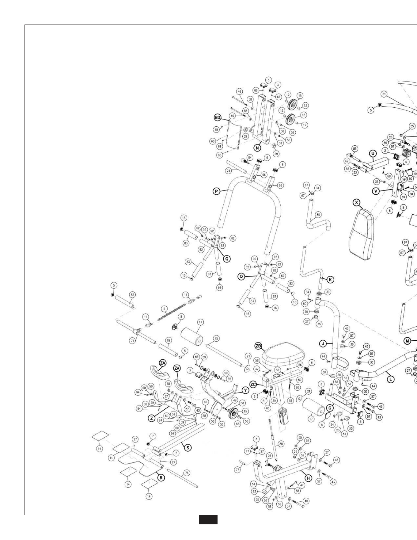
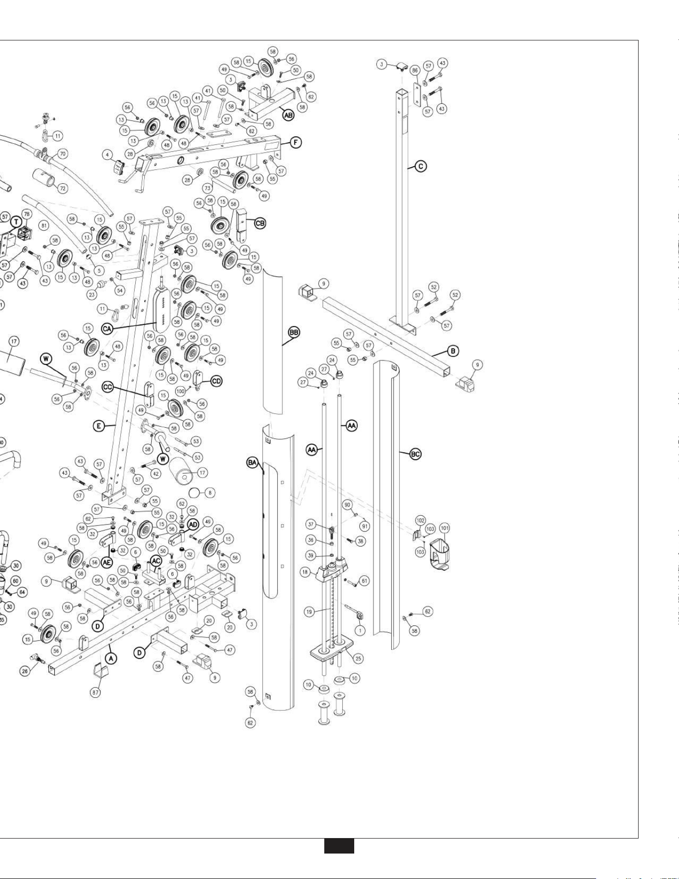
EXPLODED VIEW
DIAGRAM
G5S
38
© Copyright 2003. Body-Solid. All rights reserved. Body-Solid reserves the right to change design and specifications when we feel it will improve the product.
Body-Solid machines maintain several patented and patent pending features and designs. All rights reserved on all design patents and utility patents.
39