
TVIBH
BACKPACK CONCRETE VIBRATOR
Operation Manual
FIND THE HOW TO GUIDE ON
YEAR
W
A
R
R
A
N
T
Y
Honda Engine
on
3

2
TABLE OF CONTENTS
1. Safety Information
- Laws Pertaining to Spark Arresters
- Operating Safety
- Safety while using Combustion Engines
- Service Safety
2. Technical Data
3. Checks Before Starting
4. Machine’s Safety Rules
5. Vibrator Operation
6. Dimensions of Poker Wear
7. Maintenance
8. Troubleshooting
9. Spare Parts
10. Operation Recommendations
11. Parts Manual
12. Tomahawk Catalog and Coupon
4
5
5
6
6
7
7
8
10
11
12
15
16
17
18
29

3
Register Your Equipment
Thank you for purchasing TOMAHAWK equipment! Your product is covered by the
TOMAHAWK Warranty policy, but in order to activate your warranty, we need you to register
your product. In addition to activating your equipment warranty, product registration will
grant you access to important product updates, streamlined customer service and more.
INCLUDED WITH YOUR REGISTRATION
☑ Equipment Warranty Activation
☑ Product Updates
☑ Streamlined Customer Service
☑ Excusive Discounts and Sales
STEPS TO REGISTER YOUR EQUIPMENT
1. Visit www.tomahawk-power.com
2. Choose “Product Registration” at the bottom of the page
3. Enter your equipment’s serial number to get started
4. Provide all required information
5. Submit Registration
Equipment Resources
Tomahawk Customer Service doesn’t stop at checkout. We understand to keep a job-site
running smoothly - the proper equipment, spare parts, instruction manuals, and more are
needed at the drop of a hat. Visit www.tomahawk-power.com to gain access to the incredible
resources below.
How To Video Library
More of a visual person? Visit our Video Library for equipment
assembly instructions, troubleshooting tips, and more!
Found on each product listing or the Service Videos Page
Manual and Assembly Guide Library
Visit our Manual Library if you are looking for a lost
operations manual or a particular spare part?
Found on each product listing or the Tomahawk Manuals Page
Service Requests
In need of a quick fix or a service center referral? Submit a
Service Request and a Tomahawk Technician will respond
shortly to get you the help you need.
Choose “Service Request” at the bottom of www.tomahawk-power.com

This manual provides information and procedures to safely operate and maintain this
equipment. For your own safety and protection from injury, carefully read, understand and
observe the safety instructions described in this manual.
Keep this manual or a copy of it with the equipment. If you lose this manual or need an
additional copy, please contact Tomahawk Power LLC or visit www.tomahawk-power.com
This equipment is built with user safety in mind; however, it can present hazards if
improperly operated and serviced. Follow operating instructions carefully. If you have
questions about operating or servicing this equipment, contact Tomahawk Power.
The information contained in this manual is based on equipment’s production at the time of
publication. Tomahawk Power reserves the right to change any portion of this information
without notice.
No part of this publication may be reproduced in any form or by any means, electronic or
mechanical, including photocopying, without express written permission from
Tomahawk Power.
Any type of reproduction or distribution not authorized by Tomahawk Power represents an
infringement of valid copyrights and will be prosecuted. We expressly reserve the right to
make technical modifications, even without due notice, which aim at improving our
machines or their safety standards.
1. SAFETY INFORMATION
This manual contains DANGER, WARNING, CAUTION, and NOTE callouts which must be
followed to reduce the possibility of personal injury, damage to the equipment, or improp-
er service.
This is the safety alert symbol. It is used to alert you to potential personal injury
hazards. Obey all safety messages that follow this symbol to avoid possible injury
or death.
DANGER indicates an imminently hazardous situation which, if not avoided, will
result in death or serious injury.
WARNING indicates a potentially hazardous situation which, if not avoided, could
result in death or serious injury.
CAUTION indicates a potentially hazardous situation which, if not avoided, may
result in minor or moderate injury.
DANGER
WARNING
CAUTION
4

5
CAUTION: Used without the safety alert symbol, CAUTION indicates a potentially
hazardous situation which, if not avoided, may result in property damage.
1.1 Laws Pertaining to Spark Arresters
Notice: State Health Safety Codes and Public Resources Codes specify that in certain
locations spark arresters be used on internal combustion engines that use hydrocarbon
fuels. A spark arrester is a device designed to prevent accidental discharge of sparks or
flames from the engine exhaust. Spark arresters are qualified and rated by the United
States Forest Service for this purpose.
In order to comply with local laws regarding spark arresters, consult the engine distributor
or the local Health and Safety Administrator.
1.2 Operating Safety
Familiarity and proper training are required for the safe operation of equipment!
Equipment operated improperly or by untrained personnel can be dangerous! Read
the operating instructions contained in both this manual and the engine manual and
familiarize yourself with the location and proper use of all controls. Inexperienced
operators should receive instruction from someone familiar with the equipment before
being allowed to operate the machine.
1.2.1 NEVER allow anyone to operate this equipment without proper training. People
operating this equipment must be familiar with the risks and hazards associated with it.
1.2.2 NEVER touch the engine or muffler while the engine is on or immediately aer it has
been turned off. These areas get hot and may cause burns.
1.2.3 NEVER use accessories or attachments that are not recommended by Tomahawk
Power. Damage to equipment and injury to the user may result.
1.2.4 NEVER leave machine running unattended.
1.2.5 ALWAYS be sure operator is familiar with proper safety precautions and operation
techniques before using machine.
1.2.6 ALWAYS wear ANSI Z87.1-approved safety goggles or safety glasses with side shields,
or when needed, a face shield. Use a dust mask in dusty work conditions. Also use non-skid
safety shoes, hardhat, gloves, dust collection systems, and hearing protection when
appropriate. This applies to all persons in the work area.
1.2.7 ALWAYS close fuel valve on engines equipped with one when machine is not being
operated.
1.2.8 ALWAYS store equipment properly when it is not being used. Equipment should be
stored in a clean, dry location out of the reach of children.
WARNING

6
1.2.9 ALWAYS operate machine with all safety devices and guards in place and in working
order. DO NOT modify or remove safety devices. DO NOT operate machine if any safety
devices or guards are missing or inoperative.
1.2.10 ALWAYS read, understand, and follow procedures in Operator's Manual before
attempting to operate equipment.
1.3 Safety while using Combustion Engines
Internal combustion engines present special hazards during operation and fueling!
Read and follow warning instructions in engine owner's manual and safety guidelines
below. Failure to follow warnings and DANGER safety guidelines could result in severe
injury or death.
1.3.1 DO NOT run machine indoors or in an enclosed area such as a deep trenches unless
there is adequate ventilation, through such items as exhaust fans or hoses are provided.
Gasoline exhaust from the engine contains poisonous carbon monoxide gas; exposure to
carbon monoxide can cause loss of consciousness and may lead to death.
1.3.2 DO NOT smoke while operating machine.
1.3.3 DO NOT smoke when refueling engine.
1.3.4 DO NOT refuel hot or running engine.
1.3.5 DO NOT refuel engine near open flame.
1.3.6 DO NOT spill fuel when refueling engine.
1.3.7 DO NOT run engine near open flames.
1.3.8 ALWAYS refill fuel tank in well-ventilated area.
1.3.9 ALWAYS replace fuel tank cap aer refueling.
1.3.10 ALWAYS check fuel lines and fuel tank for leaks and cracks before starting engine.
1.3.11 DO NOT run machine if fuel leaks are present or fuel lines are loose.
1.4 Service Safety
Poorly maintained equipment can become a safety hazard! In order for the
equipment to operate safely and properly over a long period of time, periodic
maintenance and occasional repairs are necessary.
1.4.1 DO NOT attempt to clean or service machine while it is running. Rotating parts can
cause severe injury.
1.4.2 DO NOT crank a flooded engine with the spark plug removed on gasoline-powered
engines. Fuel trapped in the cylinder will squirt out the spark plug opening.
DANGER
WARNING

7
1.4.3 DO NOT test for spark on gasoline-powered engines, if engine is flooded or the smell
of gasoline is present. A stray spark could ignite fumes.
1.4.4 DO NOT use gasoline or other types of fuels or flammable solvents to clean parts,
especially in enclosed areas. Fumes from fuels and solvents can become explosive.
1.4.5 ALWAYS keep area around muffler free of debris such as leaves, paper, cartons, etc. A
hot muffler could ignite them, starting a fire.
1.4.6 ALWAYS replace worn or damaged components with spare parts designed and
recommended by Tomahawk Power.
1.4.7 ALWAYS disconnect spark plug on machines equipped with gasoline engines, before
servicing, to avoid accidental start-up.
1.4.8 ALWAYS keep machine clean and labels legible. Replace all missing and hard-to-read
labels. Labels provide important operating instructions and warn of dangers and hazards.
1.4.9 ALWAYS check for damaged parts before each use. Carefully check that the screed
will operate properly and perform its intended function. Replace damaged or worn parts
immediately. Never operate the screed with a damaged part.
1.4.10 ALWAYS inspect the screed prior to placing in storage and before re-use. Store the
screed in a dry, secure place out of the reach of children when not in use.
1.4.11 ALWAYS use only accessories that are recommended by the manufacturer for use
with the screed. Accessories that may be suitable for one Screed may create a risk of injury
when used with the screed equipment.
1.4.12 ALWAYS keep boards clean when not in use and guards in place and in working
order.
2. TECHNICAL DATA
2.1 Design and Features
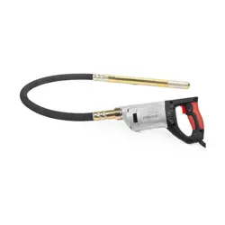
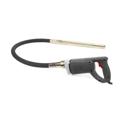
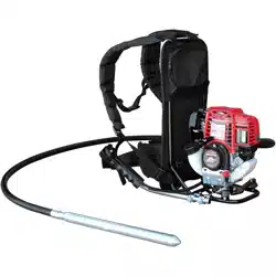
Ideal for construction, formwork, patching, and other repair jobs, the Tomahawk TVIBH
Backpack Concrete Vibrator is the perfect for removing air bubbles at 12,000 VPM to help
properly settle concrete faster. Tomahawk vibrators are designed with superior padding
with adjustable straps and cushion to distribute weight evenly to reduce operator fatigue.
2.2 Quick Connect Design
Work smarter, not harder and change vibrator shas and heads quicker than before with
Tomahawk’s Quick Connect Vibrator Design!
2.3 Honda Engine
Honda’s GX35 engine is legendary for superior reliability and performance. And there’s no
doubt about it. Low noise levels, low vibration, and low emissions – without sacrificing
power output or performance.

8
2.4 Machine Data
3. CHECKS BEFORE STARTING
3.1 Recommended Fuel
The engine requires regular grade unleaded gasoline, 89 octane or higher. Use only fresh,
clean gasoline. Gasoline containing water or dirt will damage fuel system. Consult engine
owner's manual for complete fuel specifications.
3.2 Starting Checklist
Read and understand safety and operating instructions at beginning of this manual.
• Oil level in engine
• Fuel level
• Condition of air cleaner
• Tightness of external fasteners
• Condition of fuel lines
• Wear of the spark plug
Engine Brand Honda
Engine Model GX35
Engine Type Air-cooled 4-stroke OHV
Displacement 35.8 cm3
Net Power Output* 1.3 hp (1.0 kW) @ 7,000 rpm
Net Torque 1.2 lb- (1.6 Nm) @ 5,500 rpm
Starting System Recoil
Oil Capacity 3.4 US oz (100cc)
Fuel Tank Capacity 0.67 U.S. qt (.63 liter)
Vibra�ons 10,000 - 12,000 VPM
Vibrator Type Eccentric
Sha� Connec�on Type Quick Connect
Mount Type Swivel Mounted
Weight 15 lbs
ENGINE DATE
VIBRAT
OR DATA

4. MACHINE’S SAFETY RULES
4.1 For your own safety, the safety of others, and the safety of this equipment, read
the following instructions carefully:
4.1.1 For the proper use of this device, please assure that the operator has been correctly
informed of the content of this manual before using it.
4.1.2 This machine must be used only under the applications for which it has been
designed and according to these safety instructions.
4.1.3 DO NOT touch any part of the vibrating group when the motor is running.
4.1.4 DO NOT work in an area exposed to flammable liquids or gases.
4.1.5 DO NOT allow inexperienced or not trained personnel to use the machine.
4.1.6 Please secure all the threads and bolts before working.
4.1.7 DO NOT stop the machine until the concrete mass is fully vibrated.
4.1.8 DO NOT work with the machine if any type of dysfunction, even small, has been
observed.
4.1.9 DO NOT connect the flexible sha to the motor when this is working.
4.1.10 DO NOT operate in the motor sha when this is working and without transmission
4.1.11 DO NOT work with transmission or poker in bad conditions, the motor overheats.
4.1.12 DO NOT permit untrained personnel to operate the motor or connections.
4.1.13 Read the engine manufacturer's manual BEFORE working.
4.1.14 DO NOT work in closed rooms, as the exhaust fumes may be toxic.
4.1.15 Wait 2 minutes for the petrol refill until the motor gets cold.
4.1.16 Keep the air intake clean and open for the correct running of the motor.
4.1.17 The vibration that transmitted to the operator does not exceed 8.2 fps2 of
acceleration.
4.2 Usage Conditions
For your own safety, the safety of others, and the safety of this equipment, read the
following instructions carefully:
4.2.1 Before working, be sure the hose joint nut is fastened to the motor (screwed to LEFT).
4.2.2 Make sure the poker is well screwed to the flexible sha (screwed to LEFT).
4.2.3 DO NOT work with a flexible sha with big bends.
4.2.4 DO NOT over lubricate the sha.
4.2.5 DO NOT keep working the poker out of the concrete for more than 5 minutes.
4.2.6 DO NOT restrict the movement of the poker during the work.
4.2.7 DO NOT stop the poker inside the concrete.
4.2.8 Change the wear parts to avoid damage to the internal parts.
4.2.9 Do the maintenance with the kinds and quantities of recommended lubricants.
9

5. VIBRATOR OPERATION
5.1 Before Starting
5.1.1 Before working, make sure that all the security devices are operating under normal
conditions.
5.1.2 Read the engine manufacturer manual thoroughly.
5.1.3 DO NOT work in rooms with scarce ventilation.
5.1.4 Make sure there is NO flammable good near to the escape.
5.1.5 Check the petrol level in the reservoir (use always unleaded gas in 4 stroke engines).
5.1.6 Check the oil reservoir of the motor is full (see engine manual) in the 4-stroke engine
(SAE10W30).
5.1.7 Check all the bolts are well tightened.
5.1.8 Start the motor, regulate the speed with the accelerator until it reaches a good
vibration.
5.1.9 When a defect or a malfunction has been detected, endangering the use of this
machine or not, stop the work and make the correspondent maintenance to avoid any
danger or bigger damage.
5.2 Getting Started
Read item #5 in USAGE CONDITIONS
5.3 Sha Connection to Power Unit
The power unit is designed to facilitate a quick and safe connection to the flexible sha.
5.4 Connection Procedure
5.4.1 Connect the transmission sha to the square engine housing.
5.4.2 Screw the plastic nut of the sha to the aluminium thread of the power unit.
5.4.3 The nut turns le.
5.4.4 No tool is required.
5.5 Connection Choices
5.5.1 Flexible Sha Length: TVW10-P 10.
5.5.2 Vibrator Head Diameter: 1” (TVW10-P-1) and 2” (TVW10-P-2)
5.6 Poker Connection to Flexible Sha
CONNECTION PROCEDURE:
5.6.1 Introduce the hexagonal driver of the poker in the sha.
5.6.2 Screw the poker on the screwed end of the transmission up to fasten with a spanner
(le threads).
10
5.7 Inspection
5.7.1 Before starting the job, ensure that all handling and safety devices are working
correctly.
5.7.2 Regularly inspect the condition of the transmission to ensure it is in good condition.
When the hose is broken, repair it or replace it to avoid damaging the sha or the poker.
5.7.3 Replace parts that are worn down.
5.7.4 If defects are found in the safety devices or other defects which could reduce the safe
handling of the equipment, notify the person in charge immediately.
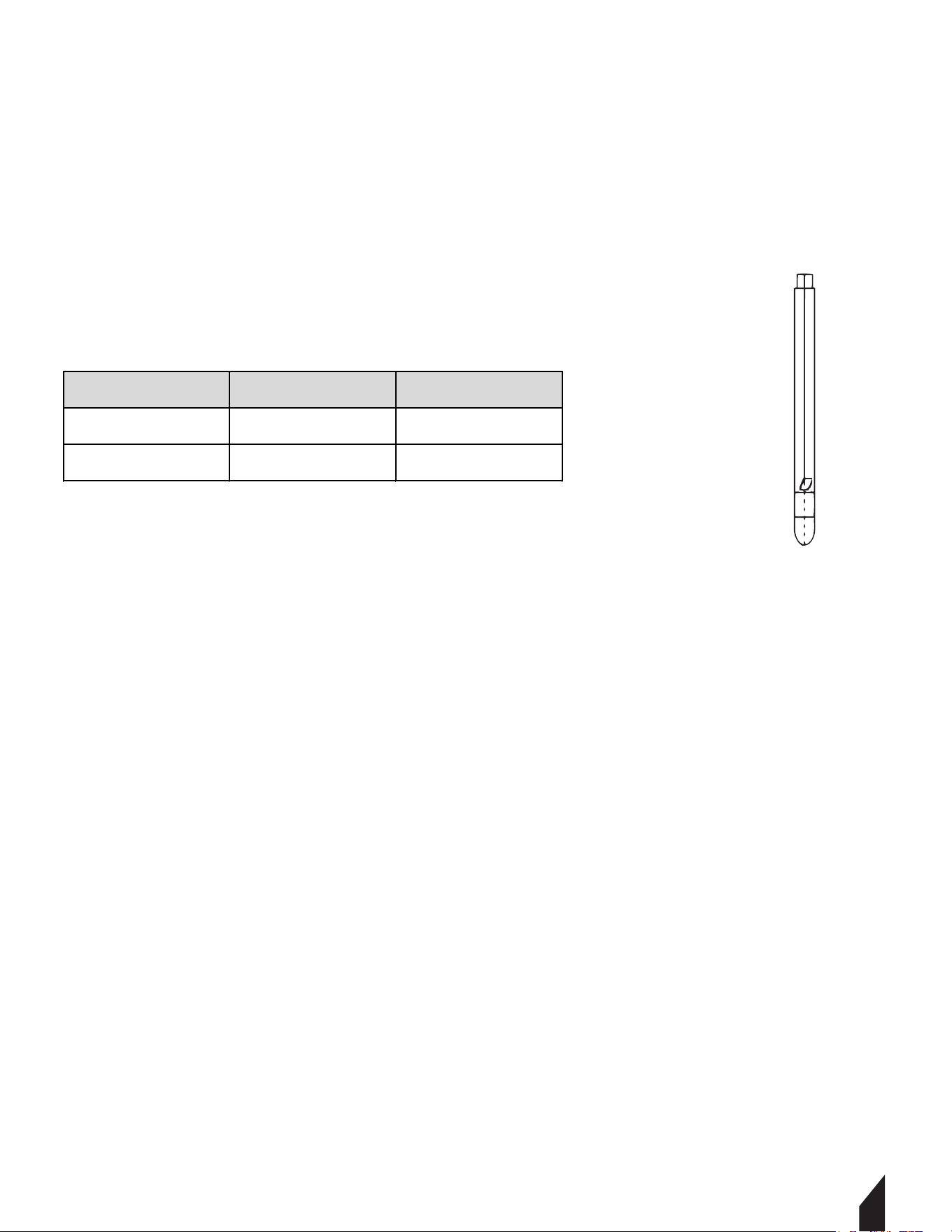
6. DIMENSIONS OF WEAR FOR THE POKERS
6.1.1 The minimum dimensions are printed in bold.
6.1.2 The dimensions within brackets are the original dimensions.
6.1.3 Replace the housing when it has been worn down to the minimum diameter.
6.1.4 Replace the tip when it has reached the minimum length.
11
MODEL DIAMETER (inch) LENGTH (inch)
TVW10-P1 1 12
TVW10-P2 2 12

12
7. MAINTENANCE
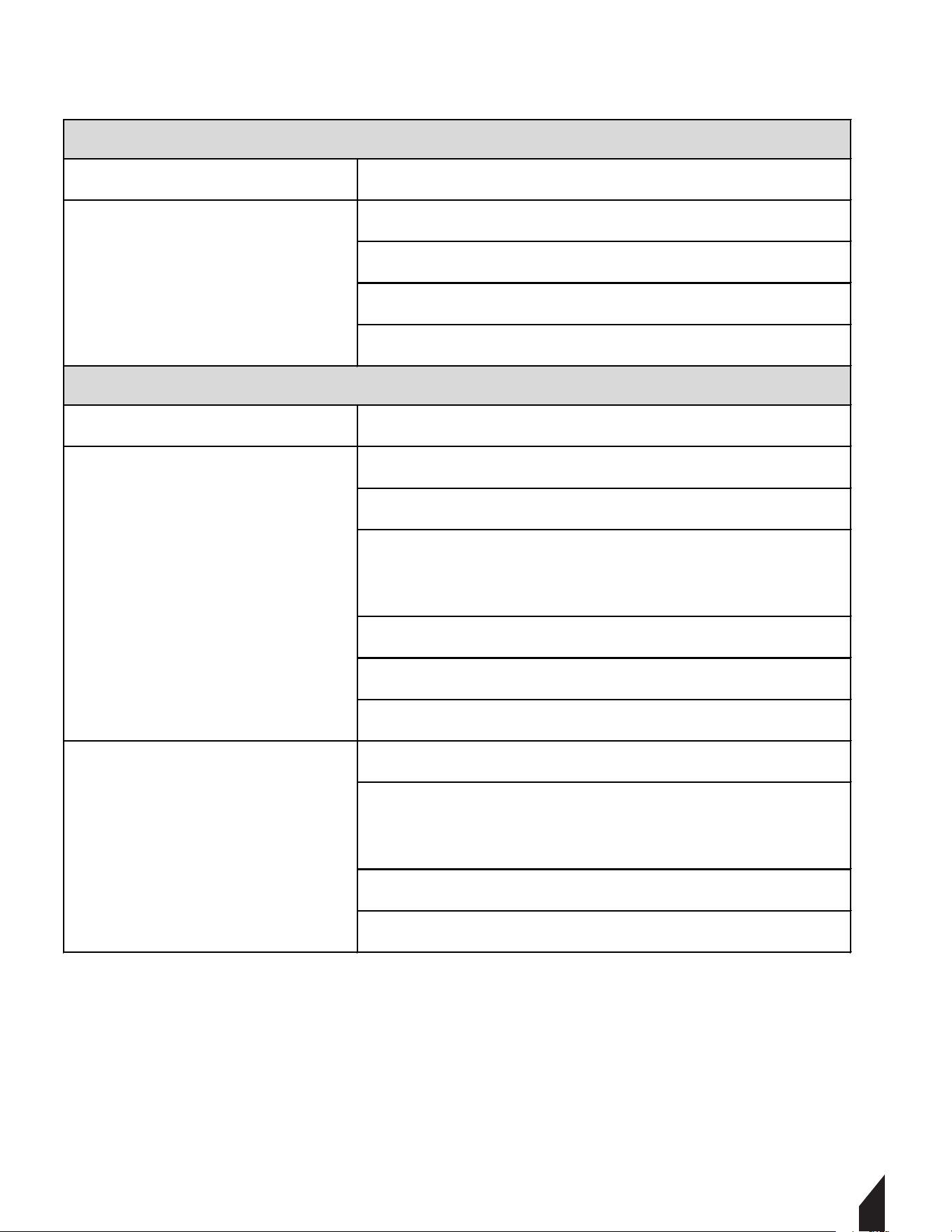
7.1 Maintenance Table
Maintain the equipment in accordance with the following recommended procedures. Refer
to the engine manufacturer’s instruction manual for additional information about engine
maintenance. The following chart is based on a normal operation schedule.
Clean the engine and beams
Set the valves
Replace the spark plug
Check the nuts and bolts
Check the engine and fill with oil
Change the motor oil (first 20
hours of use)
Clean the air filter
Adjust the spark plugs as needed
Clean the carburetor
Clean the spark plugs
Clean the oil filter
MONTHLY
(BEFORE STARTING
WEEKLY
(EVERY 50 HOURS)
MONTHLY
(EVERY 200 HOURS)
QUARTERLY
(EVERY 250 HOURS)
Clean the spark plugs
Clean the cylinder head

7.2 Additional Maintenance Information
7.2.1 Safety fittings must be checked aer every maintenance check.
7.2.2 Always use the original parts for every maintenance check.
7.2.3 DO NOT fill the fuel tank near any potential source of danger. (EX: while smoking)
7.2.4 Lock the petrol admission key while filling the fuel tank.
7.2.5 Use unleaded, clean gas.
7.2.6 The “idle” speed of the motor cannot exceed 3,000RPM. Check this speed during
maintenance checks.
7.2.7 Refer to the engine’s manual for correct information on engine speed, starting, and
stopping.
7.3 Periodic Maintenance of Flexible Sha and Pokers
7.3.1 To perform maintenance on the transmission and poker, begin by disconnecting the
motor.
7.3.2 Use only original parts in all maintenance operations.
7.3.3 Check the wear of the poker controlling- located on the outside diameter and length
of the poker.
A. Replace the housing or cap when the diameter or length is less than specified in
the reference table.
7.3.4 Lubricate the sha every 100 working hours.
A.To lubricate the sha, grasp some grease in the palm of your hand and run over
the length of the sha. The sha will have a light coating of lubricant.
B. The recommended quantity is 25 g per meter.
C. DO NOT over lubricate, as it could cause the grease to penetrate into the poker.
D. DO NOT clean the sha with solvent.
7.3.5 When the length of the sha is not equal to the length of the hose, replace.
7.3.6 Every 300 hours, change the oil of the poker.
A.To change the oil:
i. Remove the cap.
ii.Hold the housing with a clamp.
iiii.Tap the cap with a plastic hammer. This will help to break the seal and to
loosen the threads.
iv.Take out the old oil and fill the cavity of the cap with a light, non foaming
SAE40 oil or equivalent.
v.Mount the poker back into place..
vi.
If inspection reveals that the oil is a thick, heavy, sticky mixture, then the
grease of the flexible sha has penetrated into the head. Then, all seals
must be replaced.
13

7.2 Additional Maintenance Information
7.2.1 Safety fittings must be checked aer every maintenance check.
7.2.2 Always use the original parts for every maintenance check.
7.2.3 DO NOT fill the fuel tank near any potential source of danger. (EX: while smoking)
7.2.4 Lock the petrol admission key while filling the fuel tank.
7.2.5 Use unleaded, clean gas.
7.2.6 The “idle” speed of the motor cannot exceed 3,000RPM. Check this speed during
maintenance checks.
7.2.7 Refer to the engine’s manual for correct information on engine speed, starting, and
stopping.
7.3 Periodic Maintenance of Flexible Sha and Pokers
7.3.1 To perform maintenance on the transmission and poker, begin by disconnecting the
motor.
7.3.2 Use only original parts in all maintenance operations.
7.3.3 Check the wear of the poker controlling- located on the outside diameter and length
of the poker.
A. Replace the housing or cap when the diameter or length is less than specified in
the reference table.
7.3.4 Lubricate the sha every 100 working hours.
A.To lubricate the sha, grasp some grease in the palm of your hand and run over
the length of the sha. The sha will have a light coating of lubricant.
B. The recommended quantity is 25 g per meter.
C. DO NOT over lubricate, as it could cause the grease to penetrate into the poker.
D. DO NOT clean the sha with solvent.
7.3.5 When the length of the sha is not equal to the length of the hose, replace.
7.3.6 Every 300 hours, change the oil of the poker.
A.To change the oil:
i. Remove the cap.
ii.Hold the housing with a clamp.
iiii.Tap the cap with a plastic hammer. This will help to break the seal and to
loosen the threads.
iv.Take out the old oil and fill the cavity of the cap with a light, non foaming
SAE40 oil or equivalent.
v.Mount the poker back into place..
vi.If inspection reveals that the oil is a thick, heavy, sticky mixture, then the
grease of the flexible sha has penetrated into the head. Then, all seals
must be replaced.
14
7.3 Periodic Maintenance of Flexible Sha and Pokers Continued
7.3.7 Maintenance Steps:
A. Flush the parts with solvent and wipe it all down.
B. Examine the bearings, seals and hex driver.
i. If the inspection shows that grease has penetrated into the head, the oil
seals need replacement.
ii. When replacing the oil seals, mount them back to back (neoprene seal lips
face away from each other).
C. The purpose of the seals is to keep the oil of the head in, and the flexible sha
grease out. Be careful not to damage the polished surface where the seals are
located.
i. Change the seals when they are removed.
D. Fill the cavity of the cap with a light non-foaming SAE40 oil or equivalent.
E. Apply sealant before assembling.
F. Assemble the O ring.
G. Tighten and clean the excess sealant.
H. It is important all the parts are tightened securely to avoid water and cement
from entering the head.
7.3.8 Assemble all of the parts correctly once maintenance checks are completed.
7.3.9 Every 12 months (or more frequently depending on use), have the unit inspected by a
dealer authorized by Tomahawk Power.
7.4 Storage
7.4.1 When the motor will not be used for a long period of time, store in a clean, dirt-free,
protected area.
7.5 Transportation
7.5.1 When transporting the unit, ensure that the motor is safe from slipping, overturning,
and hard hits.
15
8. Troubleshooting
P ROBLEM CAUSE/SOLUTIONS
Check the gas level.
Check the gas admission key is open.
Check the de choke position.
Check the engine oil level.
P ROBLEM CAUSE/SOLUTIONS
Head is overlubricated.
Too much grease in shaft or too little
Failure of seal and the transmission grease have
gone into the head or the head oil have gone out.
Head movement is restricted.
Transmission with extreme bents.
Transmission in bad condit
ion, broken hose.
Not enough oil in the head.
The head has been working out of the concrete
during a long time.
Water has penetrated the head
The housing has received strong stroke.
The motor does not work
The motor works overload
and overheats
LOCATING MALFUNCTIONS WITH THE ENGINE
LOCATING MALFUNCTIONS OF FLEXIBLE SHAFT AND POKERS
Bearing Failure

16
9. SPARE PARTS
9.1 How to Order Spare Parts
9.1.1 For all spare parts, contact Tomahawk Power Customer Support. If Tomahawk Power
does not have the part, customer service will refer you to an authorized dealer in your
area.
9.1.2 All spare parts requested must include the part code number as stated in the Parts
Manual. Also include the manufacturer number, if available.
9.1.3 The identification plate with manufacturer and model number is located in the top
part of the motor’s plastic frame. You can also find the numbers in the Parts Manual
on the Tomahawk Power website.
9.1.4 The transmission and pokers have the manufacture number engraved outside.
9.2 Warranties
9.2.1 Your warranty is valid for 1 year aer purchasing your Concrete Vibrator.
A. This warranty covers parts with manufacturer defects.
B. The warranty will not cover a malfunction due to improper usage of the
equipment.
9.2.3 For all warranty requests, contact Tomahawk Power Customer Support.
9.2.4 The unit must be sent to Tomahawk Power, or an authorized dealer.
A. The complete address and name of the consignee must be included.
9.2.5 Customer Support will notify you if your warranty is valid.
9.2.6 Warranty will be void if any equipment has been handled by personnel outside of
Tomahawk Power, or an unauthorized dealer.
9.2.7 Tomahawk Power reserves the right to modify any part of this manual without prior
notice.*

17
10. OPERATION RECOMMENDATIONS
10.1 Choose the type of vibrator adequate to the dimensions of the structure, the distance
among the reinforcement, and the slump cone. It is recommendable to have an additional
concrete vibrator, based on the scope of your project.
10.2 Before beginning the job, check that the concrete vibrator is in good use and it works
correctly. Use safe practices and protection.
10.3 Pour the concrete in the structure, avoiding high heights. Try to pour levelled the
concrete. The thickness of every layer should be less than 50 cm. Between 30 and 50cm is
recommended.
10.4 Introduce the vibrator vertically in the concrete mass without moving it horizontally.
10.5 Do not use the vibrator to push the concrete horizontally.
10.7 The concrete vibrator should be introduced into the mass at regular intervals.
10.7.1 Intervals should be from 8 to 10 times the diameter of the poker.
10.7.2 Watch the concrete during the process of vibrating to determine the field of action
of the vibrator. This field should be overlapped to avoid areas without vibrating.
10.8 To obtain optimum compacting, plunge it 10 cm into the precedent layer to assure a
good adherence. Different layers should not be big to avoid cold joints while vibrating.
10.9 Do not push or force the vibrator into the mass, as it could be stuck in the reinforce-
ments.
10.10 The time of vibration in each point depends on the type of the concrete, the size of
the vibrator and other factors.
10.10.1 This time can be from 5 to 15 seconds aer the immersion in each point.
10.10.2 The time is shorter for a fluid mass, a vibration in excess can produce segrega-
tion.
10.11 Well vibrated concrete creates a shiny and compact surface around the poker. There
should be no more air bubbles, as well a change in the noise of the vibrator is produced.
10.12 Many flawed structures are produced due to the vibration performed in an disorder-
ly, rushed manner.
10.13 DO NOT push or force the vibrator against the reinforcement.
10.13.1 Keep a minimum distance of 7 cm from the walls.
10.14 Always remove the poker vertically with movements upwards and downwards so the
concrete fills the empty space again.
10.15 DO NOT switch off until you stop the vibration completely.
10.16 The speed when removing the vibratpr should be approximately 8 cm per second.
When the vibrator is nearly out, extract quickly to avoid shaking the surface.
10.17 In order to vibrate slabs, the poker has to be kept at an angle.
10.18 DO NOT keep the concrete vibrator out of the concrete during long periods of time.
10.19 If you do not continue vibrating, turn off the unit.
10.20 Always follow the maintenance and safety instructions.

1718
11. TIPS AND SUGGESTIONS FOR VIBRATION CONCRETE
Proper concrete vibration techniques WILL:
• Produce concrete with the maximum strength and qualities designed in the mixture.
• Bond rebar to maximize concrete strength.
• Slow down the penetration of rust-causing liquids by increasing density.
• Eliminate rock pockets and li lines.
• Minimize patchwork, improving surface appearance by removing trapped air.
Proper concrete vibration techniques WILL NOT:
• Cause segregation.
• Eliminate a significant amount of entrained air.
• Normally damage the lower layers, as long as the concrete in these lower layers
becomes plastic under the vibrating action.
For quality concrete results, we recommend the following:
1. Select the largest concrete vibrator that is suitable for the job at hand.
2. Insert the concrete vibrator vertically. Using it’s own weight, allow it to sink to the
desired depth.
a. DO NOT FORCE, as it may lock in between rebars.
3. Hold the concrete vibrator for 5 to 15 seconds. Then, slowly li it up, remaining behind
the trapped air’s upward movement.
a. Allow around 15 seconds for each 2-foot distance to avoid re-trapping the air.
4. To close the hole formed by the vibrator, move it up and down slightly.
5. To prevent churning air into the top layer, withdraw the vibrator quickly when near the
top.
6. Move the vibrator and re-insert it at a distance of 1 ½ X the “Radius Of Action”. (Shown
in diagrams on page 19)
7. Allow the vibrator to pass 3 to 6 inches into the previous layer. This knits the layers
together, ensuring a strong bond and preventing “li lines” when the forms are removed.
8. Try to limit concrete pours to 2 to 3 feet high. This way, air has less resistance to
escape.
9. DO NOT use the vibrator to move the concrete laterally, as it causes segregation.
Instead use a shovel.
a. Place the vibrator in the center of the mounds to knock them down.
19
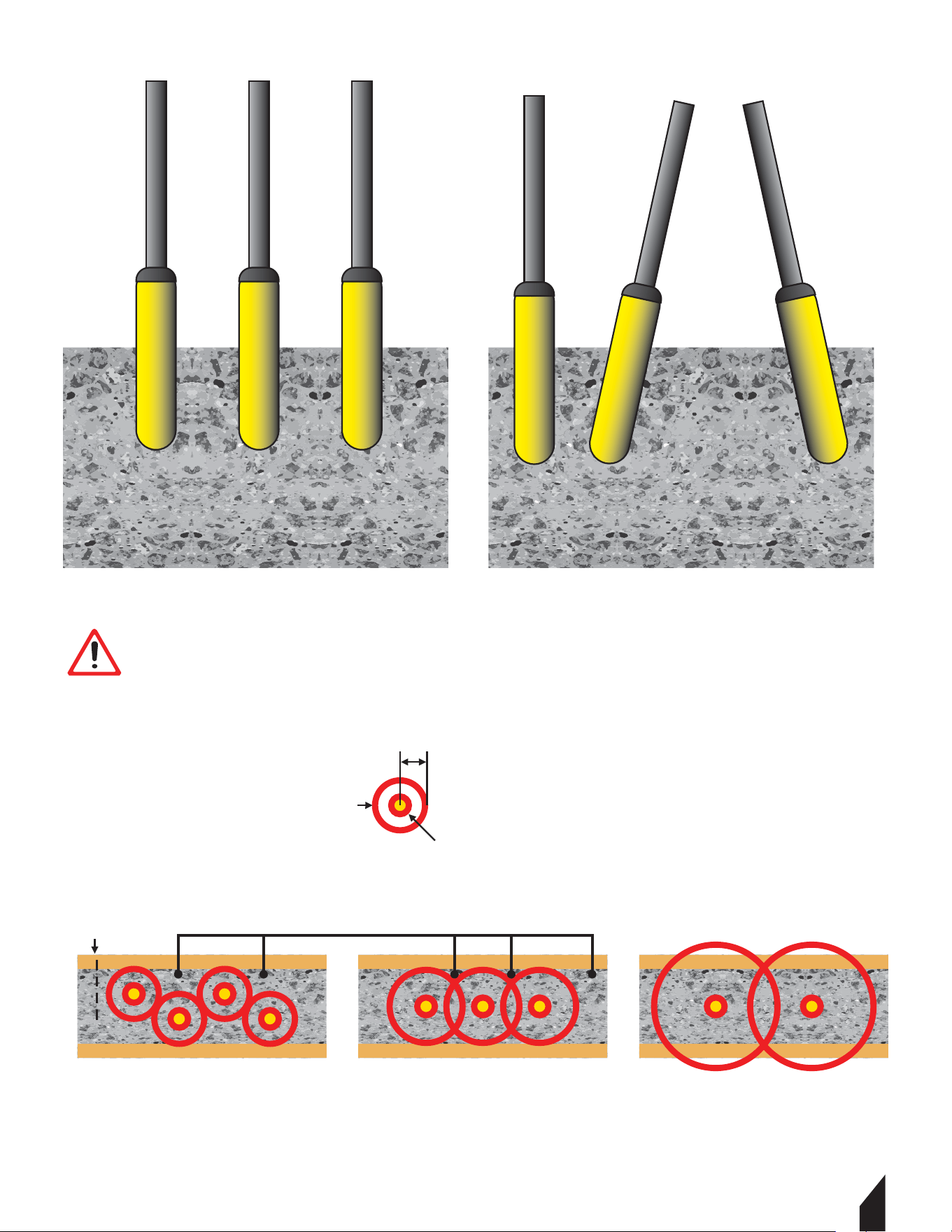
PROPER TECHNIQUE
INCORRECT TECHNIQUE
PROPER SIZETOO SMALL TOO SMALL
FORM NO VIBRATIONS
RADIUS OF VIBRATOR ACTION.....
AREA OF INFLUENCE
INSERTION POINT OF VIBRATOR
IMPORTANT
Trapped air moves upward in the mixture from 1 to 3 inches per second.
(1 inches in near 0 slump; 3 inches in 4 to 5 inch slump).

1720
11. TIPS AND SUGGESTIONS FOR VIBRATION CONCRETE CONTINUED
Consolidation eliminates the pockets of aggregate and air bubbles. This maximizes
strength and eliminates surface voids, bringing sufficient fine material to the surface and
against forms to produce the desired finish.
Concrete vibrators consolidate concrete by sending out shock waves, which allows aggre-
gate to float freely while pushing lighter trapped air up and out of the mixture.
They allow pouring stiff mixtures of concrete possible. Stiffer mixtures are stronger, more
economical, result in less segregation, less bleeding, and less shrinkage cracks.
When you have consolidated concrete properly, a thin line of mortar will appear along the
form near the vibrator, or the coarse aggregate will disappear into the concrete.
For more information regarding vibrating concrete, refer to publications from the American
Concrete Institute.

21
TVIBH
BACKPACK CONCRETE VIBRATOR

17
22

23

24

25

26

27

1728
24
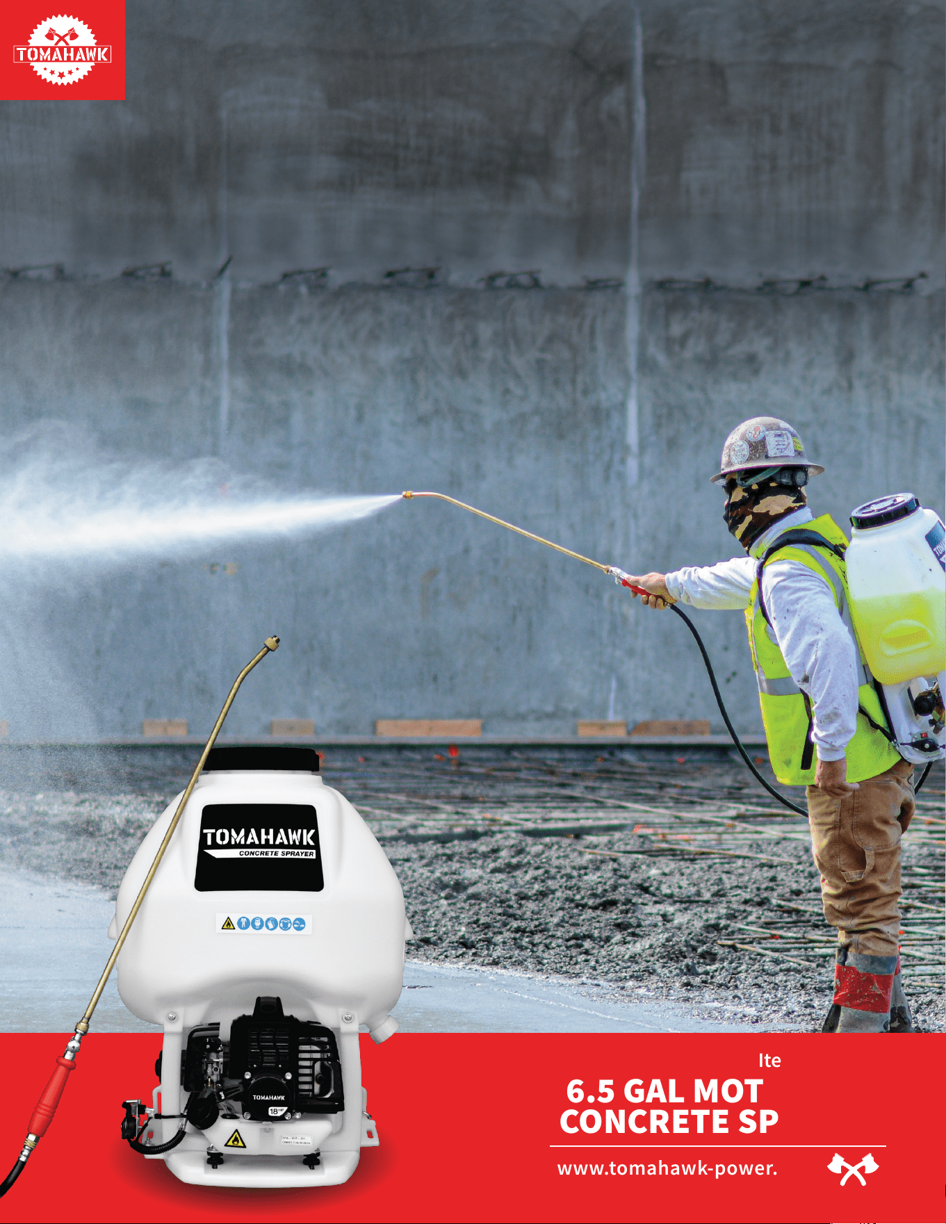
NEVER PUMP
NEVER LOSE PRESSURE
Lose the manual pump and gain the power to spray 15,000 ² in 10 minutes
or less while maintaining constant, adjustable pressure from 50-435 PSI with
your ideal concrete sealant, cure, top cast, form release, and more!
Item #: TCS6.5
6.5 GAL MOTORIZED
CONCRETE SPRAYER
www.tomahawk-power.com
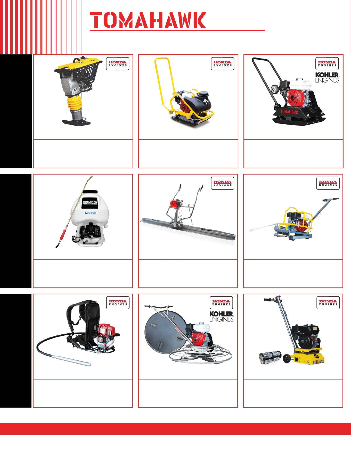
1.6HP Backpack Concrete Vibrator
Part#: TVIBH + TVW10-P
1.6 HP Honda GX35 engine
Consolidation with speeds of 10,000-12,000 VPM
Quick Connect centrifugal clutch vibrator
1” and 2” Diameter Whips Available in 10ft Length
3 Year Engine Warranty & 1 Year Product Warranty
8” Gas Powered Concrete Scarifier
Part#: TSCAR8H
5.5 HP Honda GX160 Engine
Remove traffic lines at 800 - 1,000 linear ft/hr
Tungsten Carbide Blade Kit Available
OSHA approved dust port for silica vacuum removal
3 Year Engine Warranty & 1 Year Product Warranty
36” & 46” Concrete Power Trowel
Part#: TPT36H/K & TPT46H/K
6 HP/14HP Kohler & 5.5HP/8.5HP Honda Engines
Adjust trowel blade pitch from 0-28°
60-115 RPM rotor speed for superior concrete finishes
Includes float pan and trowel blades
3 Year Engine Warranty & 1 Year Product Warranty
HAVE QUESTIONS?
Contact us. We’re here to help!
Email us at [email protected]
3,550 lbs/ft Vibratory Rammer
Part#: TR68H
3.6 HP Honda GXR120 Engine
Easily achieve a 100% compaction rating
3-in-One Fuel System with carburetor protection
13” x 11” plate for narrow trenches and corners
3 Year Engine Warranty & 1 Year Product Warranty
3,400 lbs/ft Plate Compactor
Part#: TPC90H
5.5 HP Honda GX160 Engine
Easily achieve a 100% compaction rating
22” x 20” cold, rolled steel beveled base plate
Includes 3.5 gallon water tank for asphalt compaction
3 Year Engine Warranty & 1 Year Product Warranty
3,000 lbs/ft Plate Compactor
Part#: TPC80 & TPC80H
6 HP Kohler CH260 & 5.5 HP Honda GX160 Engines
Easily achieve a 100% compaction rating
16.5” x 21.5” plate for narrow trenches and corners
Optional Honda Engine model: TPC80H
3 Year Engine Warranty & 1 Year Product Warranty
COMPACTION
6.5 Gal Backpack Concrete Sprayer
Part#: TCS6.5
Maintain constant, adjustable pressure up to 450 PSI
Achieve superior concrete finishes with even spraying
Spray 15,000 sq ft in less than 10 minutes
Compatible with major manufacturer wands
1 Year Product Warranty
1.6 HP Vibratory Concrete Screed
Part#: TVSA-H
1.6 HP Honda GX35 Engine
Aluminum Magnesium blades available from 8ft - 14ft
Finish concrete 4X faster than other screed methods
360° adjustable handle placement
3 Year Engine Warranty & 1 Year Product Warranty
6” Early Entry Green Concrete Saw
Part#: TFS6H
5.5 HP Honda GX160 Engine
Maximum cutting depth of 1 3/16 inches
OSHA compliant vacuum port for dust collection
Includes 6” early entry concrete blade
3 Year Engine Warranty & 1 Year Product Warranty
FINISHINGFINISHING
1.6HP Backpack Concrete Vibrator
Part#: TVIBH + TVW10-P
1.6 HP Honda GX35 engine
Consolidation with speeds of 10,000-12,000 VPM
Quick Connect centrifugal clutch vibrator
1” and 2” Diameter Whips Available in 10ft Length
3 Year Engine Warranty & 1 Year Product Warranty
8” Gas Powered Concrete Scarifier
Part#: TSCAR8H
5.5 HP Honda GX160 Engine
Remove traffic lines at 800 - 1,000 linear ft/hr
Tungsten Carbide Blade Kit Available
OSHA approved dust port for silica vacuum removal
3 Year Engine Warranty & 1 Year Product Warranty
36” & 46” Concrete Power Trowel
Part#: TPT36H/K & TPT46H/K
6 HP/14HP Kohler & 5.5HP/8.5HP Honda Engines
Adjust trowel blade pitch from 0-28°
60-115 RPM rotor speed for superior concrete finishes
Includes float pan and trowel blades
3 Year Engine Warranty & 1 Year Product Warranty
PRODUCT
CATALOG
HAVE QUESTIONS?
Contact us. We’re here to help!
Email us at [email protected]
3,550 lbs/ft Vibratory Rammer
Part#: TR68H
3.6 HP Honda GXR120 Engine
Easily achieve a 100% compaction rating
3-in-One Fuel System with carburetor protection
13” x 11” plate for narrow trenches and corners
3 Year Engine Warranty & 1 Year Product Warranty
3,400 lbs/ft Plate Compactor
Part#: TPC90H
5.5 HP Honda GX160 Engine
Easily achieve a 100% compaction rating
22” x 20” cold, rolled steel beveled base plate
Includes 3.5 gallon water tank for asphalt compaction
3 Year Engine Warranty & 1 Year Product Warranty
3,000 lbs/ft Plate Compactor
Part#: TPC80 & TPC80H
6 HP Kohler CH260 & 5.5 HP Honda GX160 Engines
Easily achieve a 100% compaction rating
16.5” x 21.5” plate for narrow trenches and corners
Optional Honda Engine model: TPC80H
3 Year Engine Warranty & 1 Year Product Warranty
COMPACTION
6.5 Gal Backpack Concrete Sprayer
Part#: TCS6.5
Maintain constant, adjustable pressure up to 450 PSI
Achieve superior concrete finishes with even spraying
Spray 15,000 sq ft in less than 10 minutes
Compatible with major manufacturer wands
1 Year Product Warranty
1.6 HP Vibratory Concrete Screed
Part#: TVSA-H
1.6 HP Honda GX35 Engine
Aluminum Magnesium blades available from 8ft - 14ft
Finish concrete 4X faster than other screed methods
360° adjustable handle placement
3 Year Engine Warranty & 1 Year Product Warranty
6” Early Entry Green Concrete Saw
Part#: TFS6H
5.5 HP Honda GX160 Engine
Maximum cutting depth of 1 3/16 inches
OSHA compliant vacuum port for dust collection
Includes 6” early entry concrete blade
3 Year Engine Warranty & 1 Year Product Warranty
FINISHINGFINISHING
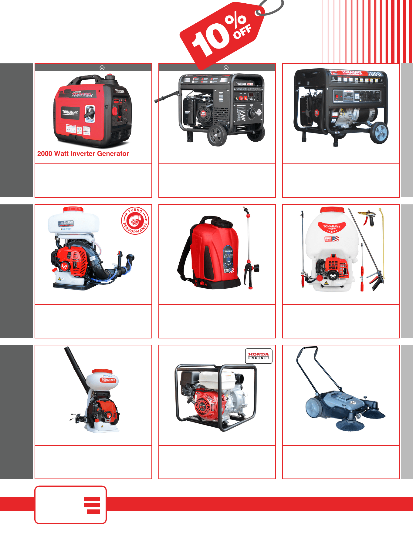
3.7 Gallon 3HP Backpack Fogger
Part#: TMD14
Turbo Boosted Pump with 40ft + Horizontal Reach
Sprays 1 acre in 30 minutes
10X Faster than Manual Pump Sprayers
Converts to Leaf Blower with 200 MPH Air Velocity
1 Year Product Warranty
Commercial 38" Push Sweeper
Part#: TOS38
Collect up to 14.5 gallons of dust and debris
Can be used indoors & outdoors on wet or dry surfaces
Includes integrated airflow control and fine dust filter
Lightweight design, capable of fitting through doorways
1 Year Product Warranty
INVERTER SERIES
210 Amp Portable Welder Generator
Part#: TWG210A
Steady 50 - 210 Amp DC welding output
60% Duty Cycle for extended use
Suitable for welding rods from 6010 to 7024
Electric Key Start with battery included
2 Year Product Warranty
7000 Watt Generators
Part#: TG7000
7000 Max Watts, 5500 Rated Watts
Voltage Selector gives Full Wattage for 120V or 240V
Run Time of 8 hours at 50% Load
OSHA and GFCI Compliant
2 Year Product Warranty
INVERTER SERIES
Part#: TG2000i
2000 Max Watts, 1600 Rated Watts
Run Time of 8 hours on 1 gallon of gas
OSHA and GFCI Compliant
Parallel technology capable for double the power
2 Year Product Warranty
2000 Watt Inverter Generator
5 Gallon Backpack Power Sprayer
Part#: TPS25
Reach Up to 30ft Horizontal Reach
Sprays acres in 10 minutes
10X Faster than Manual Pump Sprayers
50-435 Adjustable PSI Commercial Grade Pump
1 Year Product Warranty
4.75 Gallon Battery Power Sprayer
Part#: eTPS18
Reach Up to 30ft Horizontal Reach
Sprays 6000 sq ft in 10 minutes
10X Faster than Manual Pump Sprayers
70 PSI Commercial Grade Pump
1 Year Product Warranty
4 Gal. Backpack Fertilizer Spreader
Part#: TGS30
Reach up to 30ft Horizontally
Sprays 1 acre in 30 minutes
20X Faster than push spreaders
Converts to Leaf Blower with 200 MPH Air Velocity
1 Year Product Warranty
3” Full Trash Water Pump
Part#: TW3H
Moves liquids at a rate up to 375 gal/min
Handle solids up to 1.5"
Silicone carbide seals and a chrome plated volute
8 HP engine protected by rugged all purpose frame
3 Year Engine Warranty & 1 Year Product Warranty
AND MORE GENERATORSWELDING / POWER
www.tomahawk-power.com
(866) 577-4476
ASSEMBLED IN THE
PARTS SOURCED GLOBALLY
USA
INVERTER SERIESINVERTER SERIES
Part#: TG2000i
2000 Max Watts, 1600 Rated Watts
Run Time of 8 hours on 1 gallon of gas
OSHA and GFCI Compliant
Parallel technology capable for double the power
2 Year Product Warranty
2000 Watt Inverter Generator
AND MORE POWER / WELDINGPEST CONTROL
www.tomahawk-power.com
(866) 577-4476
ASSEMBLED IN THE
PARTS SOURCED GLOBALLY
USA
USE CODE
SAVE10
AT CHECKOUT FOR
10% OFF
YOUR NEXT ORDER*
* All coupons in this manual are valid only for orders placed on www.tomahawk-power.com, unless otherwise noted. Coupon codes
may only be used once per customer and may not be combined with any other offer. Coupons may expire at any time without notice.

Tomahawk Power, LLC
San Diego, CA
Sales Support
(866) 577-4476
Equipment Support
(866) 577-4476
www.tomahawk-power.com
Tomahawk understands to keep a job-site running smoothly the proper equipment and
spare parts are needed at the drop of a hat. With same day shipping and faster
delivery times, count on Tomahawk to keep you powered throughout the day! With
long lasting parts and engines, Tomahawk equipment will be the star of your fleet for
years to come. Visit www.tomahawk-power.com to get started today!
Power Your World
FACEBOOK
facebook.com/TomahawkPowerUSA
YOUTUBE
youtube.com/TomahawkPower
INSTAGRAM
@tomahawkpower