BULLETIN NO.
54-20-9370
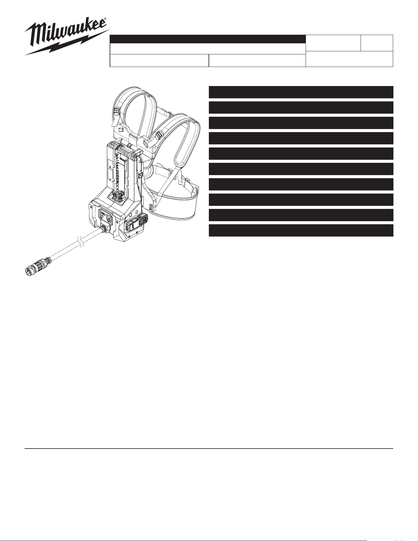
SERVICE PARTS LIST
CATALOG NO. MXF372
REVISED BULLETIN
SPECIFY CATALOG NO. AND SERIAL NO. WHEN ORDERING PARTS
MX FUEL™ HIGH CYCLE CONCRETE VIBRATOR
SERIAL NO.
DATE
May 2025
WIRING INSTRUCTION
P48A
See Pages 5-7
MILWAUKEE TOOL
l
www.milwaukeetool.com
13135 W. LISBON RD., BROOKFIELD, WI 53005
Drwg. 2
Only maintenance, service, repairs, and replacements of parts as dened in the Operator's Manual
can be performed by the user.
All other repairs are to ONLY be performed by personnel authorized by MILWAUKEE TOOL.
Do not attempt to install other parts; this COULD void your tool warranty.
For service, parts, or inquiries, contact us:
• Customer Service at 1.800.SAWDUST (1.800.729.3878)
• E-Service tool repair at: www.milwaukeetool.com/e-service
• Find a local authorized MILWAUKEE service location at Milwaukeetool.com
• Find a MILWAUKEE factory Service Center Location or MILWAUKEE factory Central Repair
Center at Milwaukeetool.com. Send the following, posted paid and insured:
• Your name, address, and phone number
• Description of the issues
• Copy of the proof of purchase
• Tool, charger, and batteries involved with the issues
MILWAUKEE factory Central Repair Centers:
MILWAUKEE TOOL MILWAUKEE TOOL
Central Repair Central Repair
1401 Sycamore Avenue 2198 Southtech Drive
Greenwood, MS 38930 Greenwood, IN 46143
OVERVIEW PAGE 2
ELECTRONICS SUB-ASSEMBLY PAGE 3
REMOTE SUB-ASSEMBLY PAGE 3
TORQUE CHART PAGE 3
BILL OF MATERIAL - BOM LISTING PAGE 4
VCU WHIP ASSEMBLY PAGE 4
WHIP ASSEMBLY PAGE 4
WIRING PAGE 5
WIRING - CONTINUED PAGE 6
WIRING - CONTINUED PAGE 7
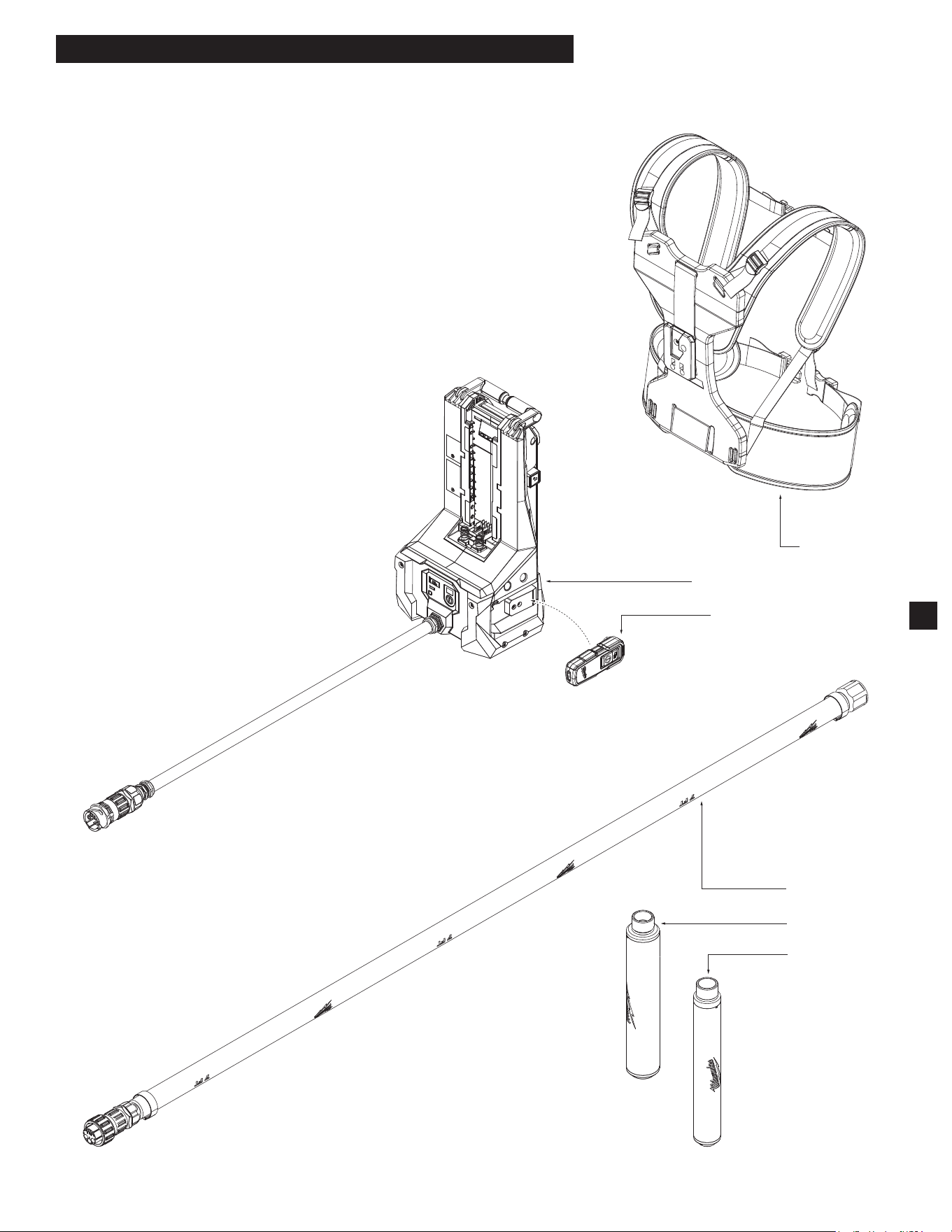
5
Electronics Assembly
Remote Assembly
400
300
200
2
MX FUEL HIGH CYCLE CONCRETE VIBRATOR
FIG. PART NO. DESCRIPTION OF PART NO. REQ.
5 1000 Quick-Release Back Plate (1)
21 48-37-0718H 48mm Head and 7' Whip Assembly, Accessory (Not Shown) (1)
22 48-37-1618H 48mm Head and 16' Whip Assembly, Accessory (Not Shown) (1)
23 48-37-3218H 48mm Head and 32' Whip Assembly, Accessory (Not Shown) (1)
31 48-37-0722H 59mm Head and 7' Whip Assembly, Accessory (Not Shown) (1)
32 48-37-1622H 59mm Head and 16' Whip Assembly, Accessory (Not Shown) (1)
33 48-37-3222H 59mm Head and 32' Whip Assembly, Accessory (Not Shown) (1)
200 --------------- 48mm Head Assembly (1)
300 --------------- 59mm Head Assembly (1)
400 --------------- Whip Assembly (1)
151
(x2)
142
106
151
(x7)
116
(x7)
154
(x4)
138
(x5)
119
125
140
114
(x2)
116
(x2)
151
(x2)
134
(x2)
118
122
108
159
160
147
107
101
133
110
153
(x2)
157
(x4)
172
171
105
151
(x7)
116
(x7)
60
59
158
(x2)
126
121
128
161
158
(x4)
132
143
127
(x5)
50
129
166
158
(x6)
163
130
102
164
165
120
105 116
151
51
128 158
159 160
161
57
102 130
132 152
163 164
165
53
127 129
143 157
54
106 116
151
52
125 140
147
55
114 118
134
56
142 151
58
0
00
EXAMPLE:
Component Parts (Small #)
Are Included When Ordering
The Assembly (Large #).
SEE PAGE 4 FOR BILL OF MATERIAL (BOM) LISTING
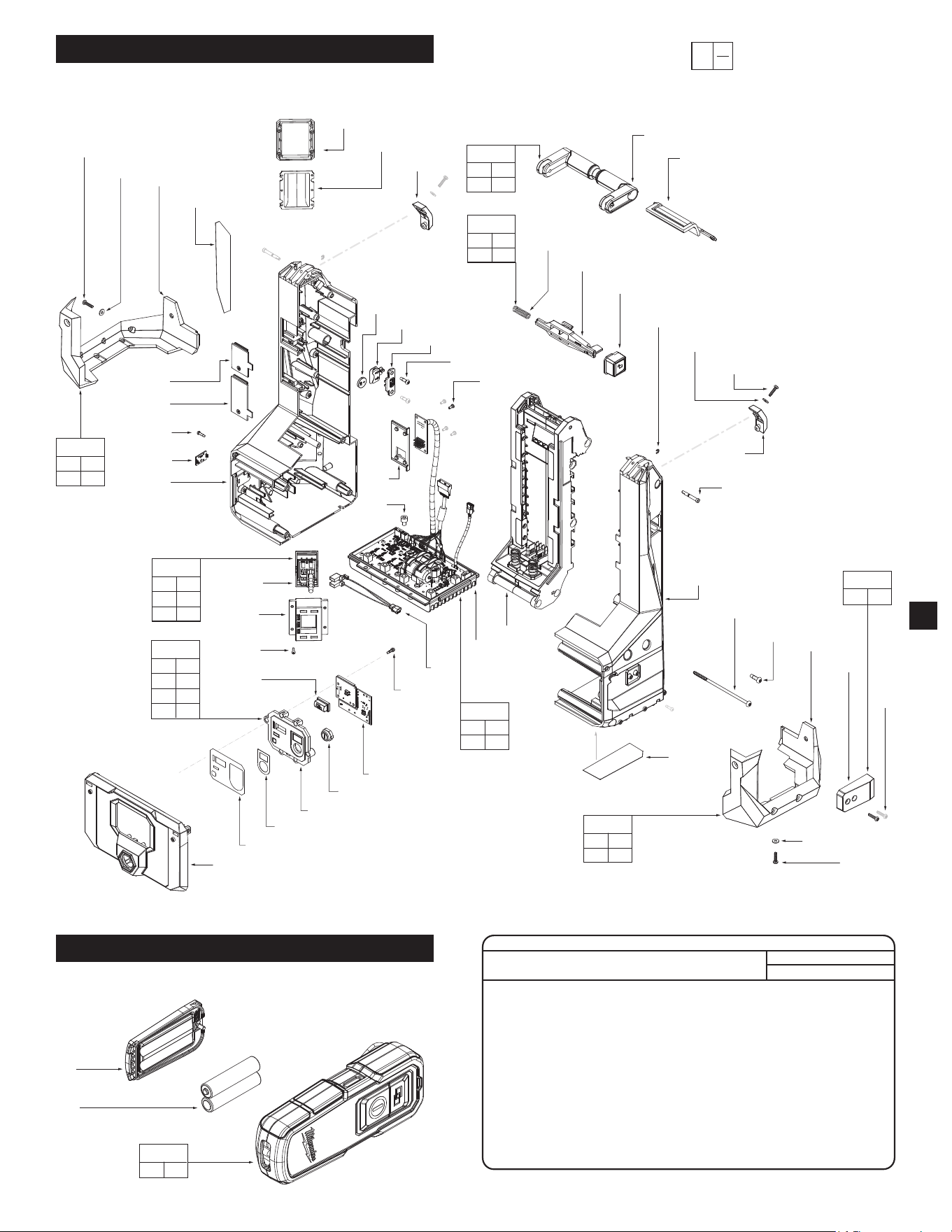
3
ELECTRONICS HOUSING ASSEMBLY
REMOTE CONTROL
61
104
(x2)
61
131
SEE PAGE 4 FOR BILL OF MATERIAL (BOM) LISTING
SCREW TORQUE SPECIFICATIONS
SEAT TORQUE
FIG. PART NO. WHERE USED (kgf-cm) (lb-in)
112 --------------- Coin Cell Cover 5-7 4-6
113 ---------------
Reprogramming Header Cover
5-7 4-6
127 06-82-9820 PCBA Board 27-33 23-29
138 05-88-0087 Housing Cover Assembly 22-28 19-24
151 06-82-0095 Brackets for Housing Support 8-12 7-10
151 06-82-0095 Remote Bracket 8-12 7-10
153 05-88-5375
Coin Cell Pocket Holder Support
10-12 9-10
154 06-82-0029 Housing Cover Assembly 22-28 19-24
157 06-82-0027
Reprogramming Header Board
7-9 4-8
158 06-82-3002 Switch Pocket
7-9 4-8
158 06-82-3002 Housing Front Panel
7-9 4-8
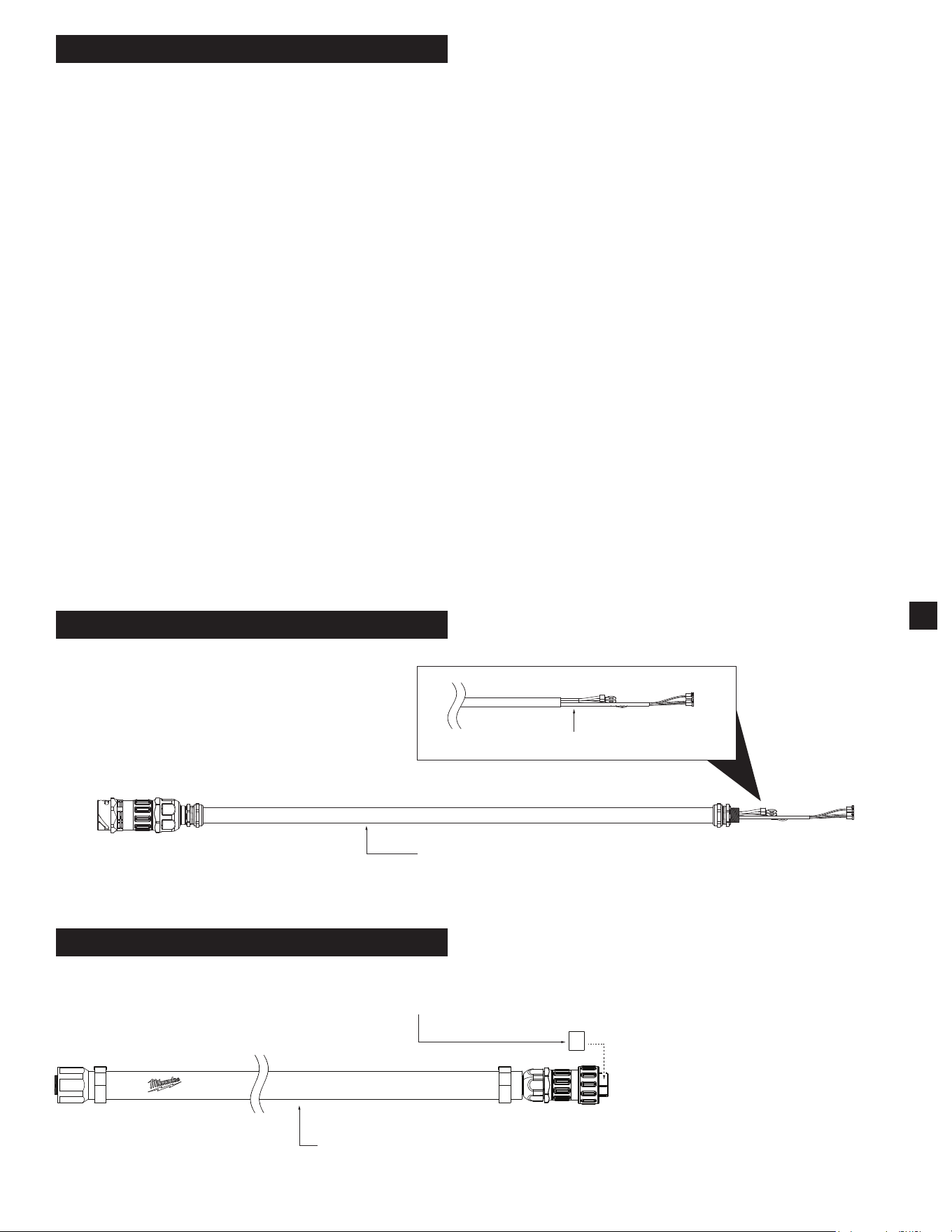
168
VCU Whip Assembly
Apply label to OD
of male connector
401
402
403
422
WHIP ASSEMBLY
4
SERVICE BILL OF MATERIAL (BOM) LISTING
FIG. PART NO. DESCRIPTION OF PART NO. REQ.
50 14-20-9501 Battery Rails Sub-Assembly (1)
51 14-46-9969 Left Bracket Kit (1)
52 14-46-9972 Right Bracket Kit (1)
53 14-46-9977 UI Assembly (1)
54 14-46-9976 PCBA Assembly (1)
55 14-46-9973 Ejector Pin Kit (1)
56 14-46-9974 Lift Handle Kit (1)
57 23-66-6530 Switch Kit (1)
58 14-46-9971 Remote Bracket Kit (1)
59 14-46-9340 Reprogramming Header Cover Assy (1)
60 14-46-9335 Coin Cell Cover Assembly (1)
61 31-21-0041 Battery Cover Assembly for Remote (1)
101 --------------- Coin Cell Battery (CR2032) (1)
- See local hardware store
102 42-42-4010 Arm Button (1)
104 --------------- AAA Battery - See local hardware store (2)
105 --------------- Left Bracket (1)
106 --------------- Right Bracket (1)
107 42-38-9060 Left Bumper (1)
108 42-38-9065 Right Bumper (1)
110 14-20-9485 Coin Cell Pocket Holder Support (1)
114 34-60-0401 E-Ring (2)
116 45-88-0377 Flat Washer (16)
118 --------------- Handle, Folding (1)
119 31-44-7265 Housing Cover Assy (1)
120 31-50-8990 Housing Front Panel (1)
121 31-44-7157 Housing Support Assy (1)
122 42-92-7110 Latch Cover VCU (1)
125 --------------- Locking Pin (1)
126 31-01-9120 Logo Plate (1)
127 06-82-9820 M6 x 7mm CH M Screw (5)
128 --------------- Jiaben K2 Switch (1)
129 --------------- PCBA Control Board Assy (1)
130 --------------- PCBA UI Arm Board (1)
131 3701 Remote Assembly (1)
132 22-68-0211 Pairing Button (1)
133 22-09-2810 PCBA Coin Cell Board (1)
134 06-65-7550 Pin (2)
138 05-88-0087 M5 x 115mm PH Torx T-20 Screw (5)
140 --------------- Release Button (1)
142 --------------- Remote Bracket (1)
143 45-60-2135
Reprogramming Header Board Holder Support
(1)
147 --------------- Compression Spring (1)
151 06-82-0095 M4 x 16mm Cap Hd. Screw (18)
153 05-88-5375
M4 x 13.5mm Pan Hd. Torx T-20 Screw
(2)
154 06-82-0029 M5 x 16mm PH Torx T-25 B Screw (4)
157 06-82-0027 M3 x 7mm Pan Hd. Torx T-10 Screw (4)
158 06-82-3002 M3 x 10mm PH Torx T-10 B Screw (12)
159 --------------- Switch Bezel (1)
160 --------------- Switch Cover (1)
161 --------------- Switch Pocket (1)
163 10-20-7259 UI Label (1)
164 --------------- UI Panel (1)
165 40-20-6707 UI Power Label (1)
166 14-20-9490 Wire Assy for Vibrator Switch (1)
168 14-20-9495 Wire Assy of Cable & Connector Assy (1)
for Control Board
171 10-22-0670 Warning Label (1)
172 12-20-9975 Service Nameplate (1)
200 --------------- 48mm Head Assembly (1)
300 --------------- 59mm Head Assembly (1)
401 --------------- 7 ft. Whip Sub-Assembly (1)
402 --------------- 16 ft. Whip Sub-Assembly (1)
403 --------------- 32 ft. Whip Sub-Assembly (1)
422 12-20-9906 Service Nameplate for Whips (1)
FIG. PART NO. DESCRIPTION OF PART NO. REQ.
VCU WHIP ASSEMBLY
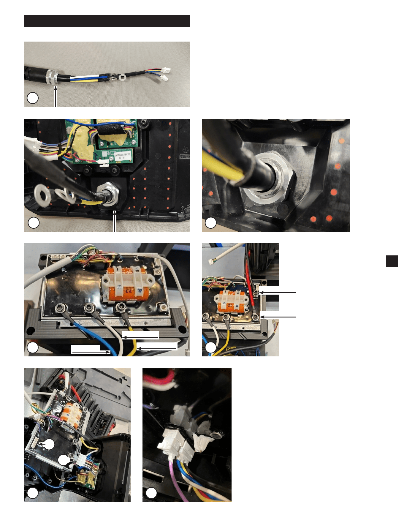
YELLOW WIRE
WHITE WIRE
BLUE WIRE
RED WIRE
BLACK WIRE
B
A
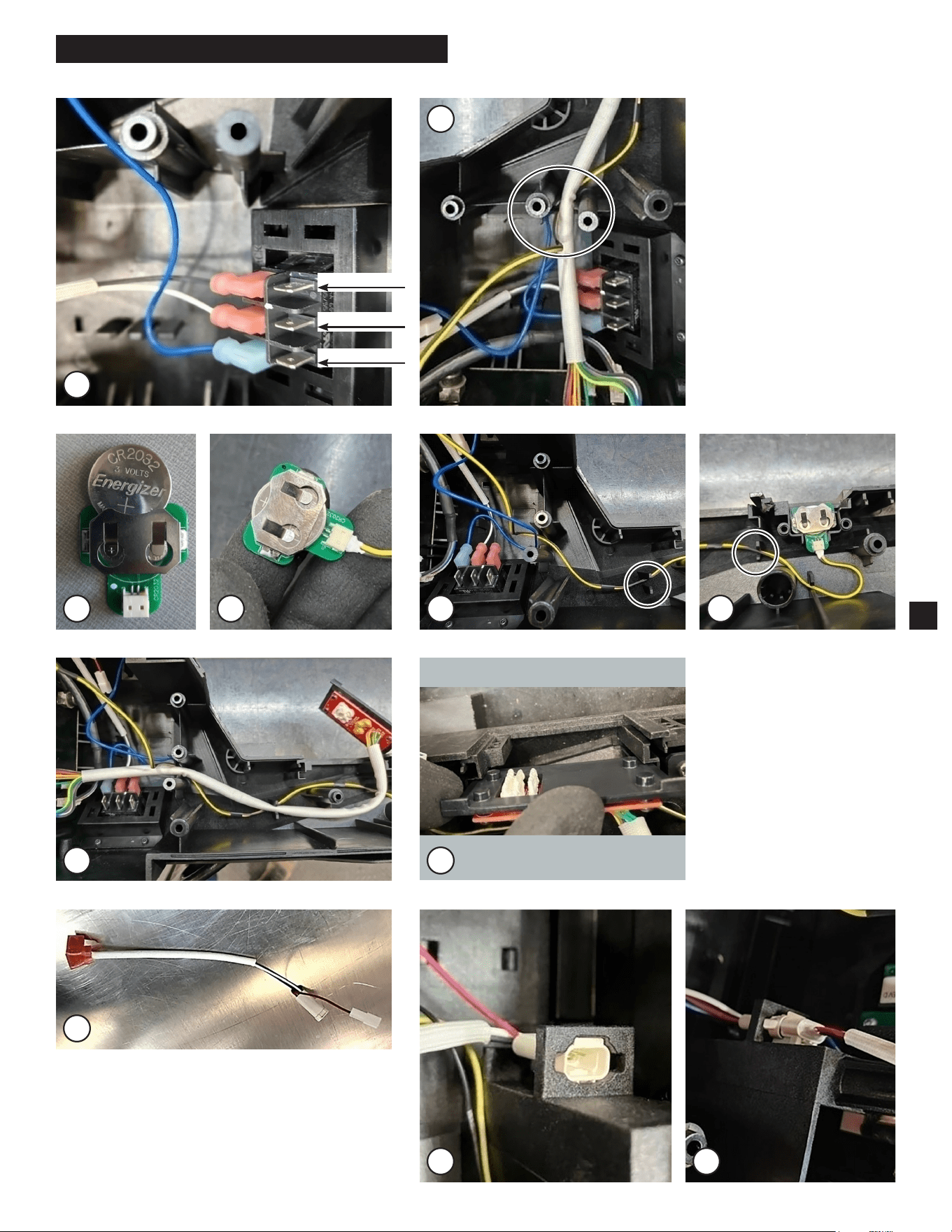
WIRING
4
1
5
6 7
2 3
5
1. Remove nut from connector assembly.
2. Thread Cable through the front panel.
3. Insert nut.
Torque to 32.5 ± 2.5 kgf-cm (28 in-lbs)
4. Attach phase wires to
PCB using M6 Screws
in order shown.
5. Attach battery to the
red and black wires
as shown.
6A. Fill two female connectors on PCB
with dielectric grease to cover pins.
6B. Plug male hall wire connectors from
wire harness.
7. Verify connectors are fully seated.
GRAY WIRE
WHITE WIRE
BLUE WIRE
WIRING - CONTINUED
9
8
6
10 11 12 13
8. Attach switch wire
harness blade clips
in order shown.
9. Make sure wires are
routed as shown.
10. Verify battery is inserted
in orientation shown.
11. Attach black/yellow wire
clip to 3V battery PCB.
12. Route 3V battery wire
through housing as
shown. Verify wire is
fully seated in wire traps.
14
13. Place 3V battery PCB
in housing half slot as
shown.
14. Route rework PCB in
housing. Verify wire
bundle is fully seated
in wire traps.
15. Place rework PCB
in housing slot in
orientation as shown.
15
16. Add dielectric grease to 3 pin connector
from switch harness.
17. Locate connector in housing slot as shown.
18. Fully seat 3 pin male side connector from
PCB assembly.
16
17
18
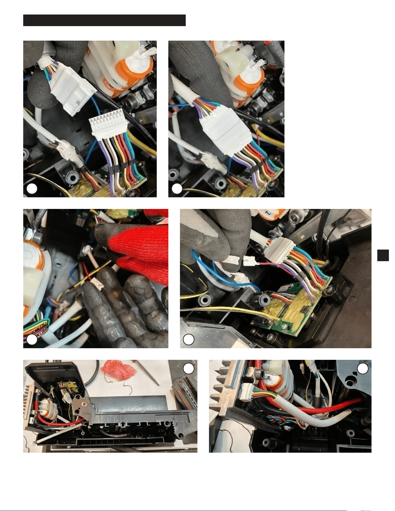
WIRING - CONTINUED
7
19
20
21
22
23 24
19. Add dielectric grease
to large connector from
PCB to cover pins.
20. Connect to male
connector from UI PCB
as shown.
21. Add dielectric grease to
cover pins to single red
wire connector.
22. Fully seat connector
with single red wire
from UI PCB.
23. Add dielectric grease to cover pins in remaining female
connector on PCB.
24. Fully seat wire bundle connector from battery rail.