
7-INCH
ANGLE GRINDER
Instruction Manual
IMPORTANT: Your new tool has been engineered and manufactured to WEN’s highest standards for dependability,
ease of operation, and operator safety. When properly cared for, this product will supply you years of rugged,
trouble-free performance. Pay close attention to the rules for safe operation, warnings, and cautions. If you use
your tool properly and for its intended purpose, you will enjoy years of safe, reliable service.
NEED HELP? CONTACT US!
Have product questions? Need technical support? Please feel free to contact us:
TECHSUPPOR[email protected]1-847-429-9263 (M-F 8AM-5PM CST)
For replacement parts and the most up-to-date instruction manuals, visit WENPRODUCTS.COM
MODEL 94487

CONTENTS
WELCOME 3
Introduction ......................................................................................................3
Specifications ....................................................................................................3
SAFETY 4
General Safety Rules .........................................................................................4
Angle Grinder Safety Warnings .........................................................................6
Electrical Information ........................................................................................8
BEFORE OPERATING 9
Unpacking & Packing List .................................................................................9
Know Your Angle Grinder ..................................................................................9
Assembly & Adjustments ................................................................................10
OPERATION & MAINTENANCE 11
Operation ........................................................................................................11
Maintenance ....................................................................................................13
Exploded View & Parts List .............................................................................14
Warranty Statement ........................................................................................16
To purchase accessories and replacement parts for your tool, visit WENPRODUCTS.COM
2

SPECIFICATIONS
INTRODUCTION
Thanks for purchasing the WEN Angle Grinder. We know you are excited to put your tool to work, but first, please
take a moment to read through the manual. Safe operation of this tool requires that you read and understand this
operator’s manual and all the labels affixed to the tool. This manual provides information regarding potential safety
concerns, as well as helpful assembly and operating instructions for your tool.
NOTE: The following safety information is not meant to cover all possible conditions and situations that may occur.
WEN reserves the right to change this product and specifications at any time without prior notice.
At WEN, we are continuously improving our products. If you find that your tool does not exactly match this manual,
please visit wenproducts.com for the most up-to-date manual or contact our customer service at 1-847-429-9263.
Keep this manual available to all users during the entire life of the tool and review it frequently to maximize
safety for both yourself and others.
Indicates danger, warning, or caution. The safety symbols and the explanations with them deserve your
careful attention and understanding. Always follow the safety precautions to reduce the risk of fire, electric shock
or personal injury. However, please note that these instructions and warnings are not substitutes for proper ac-
cident prevention measures.
Model Number 94487
Motor 120V, 60 Hz, 15A
Speed 8400 RPM
Disc Size 7 in. (180mm)
Arbor Size 5/8"-11 UNC
Inner Flange Adapter Size 1.6 in. (40mm) Diameter
Power Cord Length 6 ft.
Product Weight 10.8 lbs
Product Dimensions 18.1 in. x 3.9 in. x 6.7 in.
3

GENERAL SAFETY RULES
WORK AREA SAFETY
1. Keep work area clean and well lit. Cluttered or dark
areas invite accidents.
2. Do not operate power tools in explosive atmo-
spheres, such as in the presence of flammable liquids,
gases or dust. Power tools create sparks which may ig-
nite the dust or fumes.
3. Keep children and bystanders away while operating
a power tool. Distractions can cause you to lose control.
ELECTRICAL SAFETY
1. Power tool plugs must match the outlet. Never mod-
ify the plug in any way. Do not use any adapter plugs
with earthed (grounded) power tools. Unmodified plugs
and matching outlets will reduce risk of electric shock.
2. Avoid body contact with earthed or grounded surfac-
es such as pipes, radiators, ranges and refrigerators.
There is an increased risk of electric shock if your body
is earthed or grounded.
3. Do not expose power tools to rain or wet conditions.
Water entering a power tool will increase the risk of elec-
tric shock.
4. Do not abuse the cord. Never use the cord for car-
rying, pulling or unplugging the power tool. Keep cord
away from heat, oil, sharp edges or moving parts.
Damaged or entangled cords increase the risk of electric
shock.
5. When operating a power tool outdoors, use an ex-
tension cord suitable for outdoor use. Use of a cord
suitable for outdoor use reduces the risk of electric
shock.
6. If operating a power tool in a damp location is un-
avoidable, use a ground fault circuit interrupter (GFCI)
protected supply. Use of a GFCI reduces the risk of elec-
tric shock.
PERSONAL SAFETY
1. Stay alert, watch what you are doing and use com-
mon sense when operating a power tool. Do not use a
power tool while you are tired or under the influence
of drugs, alcohol or medication. A moment of inatten-
tion while operating power tools may result in serious
personal injury.
2. Use personal protective equipment. Always wear
eye protection. Protective equipment such as a respira-
tory mask, non-skid safety shoes and hearing protection
used for appropriate conditions will reduce the risk of
personal injury.
3. Prevent unintentional starting. Ensure the switch is
in the off-position before connecting to power source
and/or battery pack, picking up or carrying the tool.
Carrying power tools with your finger on the switch or
energizing power tools that have the switch on invites
accidents.
4. Remove any adjusting key or wrench before turning
the power tool on. A wrench or a key left attached to a
rotating part of the power tool may result in personal
injury.
5. Do not overreach. Keep proper footing and balance
at all times. This enables better control of the power
tool in unexpected situations.
6. Dress properly. Do not wear loose clothing or jew-
elry. Keep your hair and clothing away from moving
parts. Loose clothes, jewelry or long hair can be caught
in moving parts.
Safety is a combination of common sense, staying alert and knowing how your item works. The term “power tool”
in the warnings refers to your mains-operated (corded) power tool or battery-operated (cordless) power tool.
SAVE THESE SAFETY INSTRUCTIONS.
WARNING! Read all safety warnings and all instructions. Failure to follow the warnings and instructions may
result in electric shock, fire and/or serious injury.
4

GENERAL SAFETY RULES
7. If devices are provided for the connection of dust
extraction and collection facilities, ensure these are
connected and properly used. Use of dust collection
can reduce dust-related hazards.
POWER TOOL USE AND CARE
1. Do not force the power tool. Use the correct power
tool for your application. The correct power tool will
do the job better and safer at the rate for which it was
designed.
2. Do not use the power tool if the switch does not turn
it on and off. Any power tool that cannot be controlled
with the switch is dangerous and must be repaired.
3. Disconnect the plug from the power source and/or
the battery pack from the power tool before making
any adjustments, changing accessories, or storing
power tools. Such preventive safety measures reduce
the risk of starting the power tool accidentally.
4. Store idle power tools out of the reach of children
and do not allow persons unfamiliar with the power
tool or these instructions to operate the power tool.
Power tools are dangerous in the hands of untrained us-
ers.
5. Maintain power tools. Check for misalignment or
binding of moving parts, breakage of parts and any
other condition that may affect the power tool’s opera-
tion. If damaged, have the power tool repaired before
use. Many accidents are caused by poorly maintained
power tools.
6. Keep cutting tools sharp and clean. Properly main-
tained cutting tools with sharp cutting edges are less
likely to bind and are easier to control.
7. Use the power tool, accessories and tool bits, etc.
in accordance with these instructions, taking into ac-
count the working conditions and the work to be per-
formed. Use of the power tool for operations different
from those intended could result in a hazardous situa-
tion.
8. Use clamps to secure your workpiece to a stable
surface. Holding a workpiece by hand or using your
body to support it may lead to loss of control.
9. KEEP GUARDS IN PLACE and in working order.
SERVICE
1. Have your power tool serviced by a qualified repair
person using only identical replacement parts. This
will ensure that the safety of the power tool is main-
tained.
CALIFORNIA PROPOSITION 65 WARNING
Some dust created by power sanding, sawing, grinding,
drilling, and other construction activities may contain
chemicals, including lead, known to the State of Califor-
nia to cause cancer, birth defects, or other reproductive
harm. Wash hands after handling. Some examples of
these chemicals are:
• Lead from lead-based paints.
• Crystalline silica from bricks, cement, and other
masonry products.
• Arsenic and chromium from chemically treated
lumber.
Your risk from these exposures varies depending on
how often you do this type of work. To reduce your ex-
posure to these chemicals, work in a well-ventilated area
with approved safety equipment such as dust masks
specially designed to filter out microscopic particles.
5
Safety is a combination of common sense, staying alert and knowing how your item works. The term “power tool”
in the warnings refers to your mains-operated (corded) power tool or battery-operated (cordless) power tool.
SAVE THESE SAFETY INSTRUCTIONS.
WARNING! Read all safety warnings and all instructions. Failure to follow the warnings and instructions may
result in electric shock, fire and/or serious injury.

ANGLE GRINDER SAFETY WARNINGS
WARNING! Do not operate the power tool until you have read and understood the following instructions and
the warning labels.
ANGLE GRINDER SAFETY
1. Tool purpose. This power tool is intended to function
as a grinder and sander. Using the tool for operations for
which the it was not designed may create a hazard and
cause personal injury.
2. Work environment. Do not operate the tool in wet
or damp conditions; doing so significantly increases the
risk of electrical shock. Do not operate the tool in the
presence of flammable liquids or gases; sparks generat-
ed by the grinder could ignite these flammable materials.
3. Personal Safety. Always wear ANSI Z87.1-approved
glasses with side shields., hearing protection and a dust
mask when using the angle grinder. Tie back long hair.
Do not wear loose clothing or jewelry as they might get
drawn in by the tool.
4. Tool and accessory inspection. Before operation,
check the tool and accessories for any damage or miss-
ing parts. Do not use the tool if any part is missing or
damaged. Make sure all adjustments are correct and all
connections are tight. Keep all guards in place.
5. Preventing electric shock. Hold your power tool by
the insulated gripping surfaces, especially when per-
forming an operation where the accessory could con-
tact hidden wiring or its own cord. Contact with a “live”
wire will make exposed metal parts of the tool “live” and
shock the operator. Always be aware of power cord loca-
tion to avoid accidentally contacting the power cord.
6. Use the right grinding wheel for your tool and the
workpiece.
• The rated speed of the accessory must be equal to
or higher than the operation speed (8000 RPM) of the
angle grinder. Accessories running faster than the rated
speed can fly apart and cause injury.
• Use grinding wheels with 7 inch outer diameter and
a 5/8”-11 threaded arbor or 7/8 inch unthreaded arbor.
The grinding wheel thickness should not exceed 1/4
inch. Incorrectly sized accessories cannot be adequately
guarded or controlled.
7. Securing the workpiece. Secure any loose workpiec-
es using vises or clamps to prevent wobble, damage to
the workpiece, and personal injury.
8. Starting the tool. Hold the tool with both hands in
front and away from you. Do not run the tool while car-
rying it at your side. Start the angle grinder before apply-
ing it to the workpiece. Let the wheel come to full speed
before contacting the workpiece.
9. During operation. To prevent personal injury, main-
tain a firm grip on the tool with both hands. Keep hands,
hair and other beloved body parts away from the rotating
components of the tool.
10. Turning off the tool. Lift the tool from the workpiece
before turning the machine off. Do not lay the tool down
until it has come to a complete stop. Do not touch the
pad or the workpiece immediately after operation. They
may be extremely hot and could burn your skin.
11. Making adjustments. Always turn off and unplug
the grinder before cleaning, making adjustments or
changing attachments. Accidental start-ups may occur
if the tool is plugged in during an accessory change or
adjustment.
12. Cleaning after use. Blow off the motor vents and
power switch after every use, using compressed air (not
to exceed 25 PSI). Failure to do so can lead to buildup
of grinding debris and dust, possibly leading to motor or
switch failure.
6

REDUCING KICKBACK
Kickback is a sudden reaction to a pinched or snagged
rotating grinding wheel or any other accessory. Pinching
or snagging causes rapid stalling of the rotating acces-
sory which in turn causes the uncontrolled power tool
to be jump toward or away from the operator, depend-
ing on direction of the wheel’s movement at the point
of pinching. Take proper safety prevention methods to
reduce the risk of kickback:
1. Maintain a firm grip on the power tool and position
your body and arm to allow you to resist kickback forc-
es. Always use the auxiliary handle for maximum control
over kickback or torque reaction during start-up. The op-
erator can control torque reactions or kickback forces, if
proper precautions are taken.
2. Never place your hand near the rotating accessory.
Accessories may kick back over your hand.
3. Do not position your body in the area where power
tool will move if kickback occurs. Kickback will propel
the tool in direction opposite to the wheel’s movement at
the point of snagging.
4. Use special care when working corners, sharp edges
etc. Avoid bouncing and snagging the accessory. Cor-
ners, sharp edges or bouncing have a tendency to snag
the rotating accessory and cause loss of control or kick-
back.
ANGLE GRINDER SAFETY WARNINGS
VIBRATION SAFETY
This tool vibrates during use. Repeated or long-term
exposure to vibration may cause temporary or perma-
nent physical injury, particularly to the hands, arms and
shoulders. To reduce the risk of any vibration-related in-
jury:
1. First be examined by a doctor and then have regular
medical check-ups to ensure medical problems are not
being caused or worsened from use. Pregnant women
or people who have impaired blood circulation to the
hand, past hand injuries, nervous system disorders, dia-
betes, or Raynaud’s disease should not use this tool. If
you feel any symptoms related to vibration (such as tin-
gling, numbness, and white or blue fingers), seek medi-
cal advice as soon as possible.
2. Do not smoke during use. Nicotine reduces the blood
supply to the hands and fingers, increasing the risk of
vibration-related injury.
3. Wear suitable gloves to reduce the effects of vibration.
4. Use tools with the lowest vibration when there is a
choice.
5. Take vibration-free breaks during each day of work.
6. To reduce vibration, maintain the tool as explained in
this manual. If any abnormal vibration occurs, stop us-
ing the tool immediately.
7
WARNING! Do not operate the power tool until you have read and understood the following instructions and
the warning labels.

ELECTRICAL INFORMATION
AMPERAGE
REQUIRED GAUGE FOR EXTENSION CORDS
25 ft. 50 ft. 100 ft. 150 ft.
15A 14 gauge 12 gauge Not Recommended
IMPORTANT: Servicing a double-insulated product requires extreme care and knowledge of the system, and
should be done only by qualified service personnel using identical replacement parts. Always use original factory
replacement parts when servicing.
1. Polarized Plugs. To reduce the risk of electric shock, this equipment has a polarized plug (one blade is wider
than the other). This plug will fit in a polarized outlet only one way. If the plug does not fit fully in the outlet, reverse
the plug. If it still does not fit, contact a qualified electrician to install a proper outlet. Do not modify the machine
plug or the extension cord in any way.
2. Ground fault circuit interrupter protection (GFCI) should be provided on the circuit or outlet used for this power
tool to reduce the risk of electric shock.
3. Service and repair. To avoid danger, electrical appliances must only be repaired by a qualified service technician
using original replacement parts.
GUIDELINES AND RECOMMENDATIONS FOR EXTENSION CORDS
When using an extension cord, be sure to use one heavy enough to carry the current your product will draw. An
undersized cord will cause a drop in line voltage, resulting in loss of power and overheating. The table below shows
the correct size to be used according to cord length and ampere rating. When in doubt, use a heavier cord. The
smaller the gauge number, the heavier the cord.
DOUBLE-INSULATED TOOL
The tool’s electrical system is double-insulated where two systems of insulation are provided. This
eliminates the need for the usual three-wire grounded power cord. Double-insulated tools do not need
to be grounded, nor should a means for grounding be added to the product. All exposed metal parts are
isolated from the internal metal components with protecting insulation.
1. Examine extension cord before use. Make sure your extension cord is properly wired and in good condition.
Always replace a damaged extension cord or have it repaired by a qualified person before using it.
2. Do not abuse extension cord. Do not pull on cord to disconnect from receptacle; always disconnect by pulling on
plug. Disconnect the extension cord from the receptacle before disconnecting the product from the extension cord.
Protect your extension cords from sharp objects, excessive heat and damp/wet areas.
3. Use a separate electrical circuit for your tool. This circuit must not be less than a 12-gauge wire and should be
protected with a 15A time-delayed fuse. Before connecting the motor to the power line, make sure the switch is in
the OFF position and the electric current is rated the same as the current stamped on the motor nameplate. Running
at a lower voltage will damage the motor.
8
9
KNOW YOUR ANGLE GRINDER
TOOL PURPOSE
Grind metal, cut tile, sand, polish and sharpen all with your WEN Angle Grinder. Refer to the following diagrams to
become familiarized with all the parts and controls of your angle grinder. The components will be referred to later in
the manual for assembly and operation instructions.
Auxiliary Handle
Grinding Disc Cover
Grinding Disc
Spindle Lock
Trigger Lock
Angle Adjustment Lock
Power Cord
Directional Arrow
Threaded Handle Hole
UNPACKING
Carefully remove the angle grinder from the packaging and place it on a sturdy, flat surface. Make sure to take out
all contents and accessories. Do not discard the packaging until everything is removed. Check the packing list below
to make sure you have all of the parts and accessories. If any part is missing or broken, please contact customer
service at 1-847-429-9263 (M-F 8-5 CST), or email [email protected].
UNPACKING & PACKING LIST
PACKING LIST
Description Quantity
Angle Grinder 1
7-Inch Grinding Disc 1
Disc Guard 1
Auxiliary Handle 1
Lock Nut Wrench 1
Pair of Carbon Brushes 1
Power Trigger
10
ASSEMBLY & ADJUSTMENTS
WHEEL GUARD INSTALLATION
Fig. 1
1
WARNING! Use the wheel guard with disc grinding
wheels. Always close the locking handle to secure the guard.
Keep the guard between you and the wheel. Do not direct the
guard opening toward your body.
The position of the guard can be adjusted to accommodate the
operation being performed.
1. Make sure that the tool is OFF and removed from the power
supply before installing the wheel guard.
2. Loosen the guard locking handle (Fig. 1 - 1) and position the
guard on to the spindle neck so that the bump on the guard lines
up between the notches on the spindle neck.
3. Rotate the guard in either direction to the desired position.
Lock the guard locking handle to secure the guard in place.
INSTALLING & REMOVING THE GRINDING DISC
1. Turn the tool OFF and remove it from the power supply. Make
sure that the wheel guard (Fig. 2 - 1) has been properly installed
before assembling the grinding disc.
2. Place the inner flange (Fig. 2 - 2) onto the spindle first so that
the grooves align with the spindle nut.
3. Slide the grinding disc (Fig. 2 - 3) onto the spindle.
NOTE: You may use an accessory with either a threaded arbor
(diameter 5/8”-11) or an unthreaded arbor (diameter 7/8”). If us-
ing an accessory with an unthreaded 7/8” arbor, be sure it sits
properly on the inner flange before installing the outer flange.
4. Screw the outer flange (Fig. 2 - 4) in place with the protruding
lip facing downwards. This lip should fit snugly into the center
of the grinding wheel. Tighten the outer flange in place using the
supplied lock nut wrench (Fig. 2 - 5) while pressing down on the
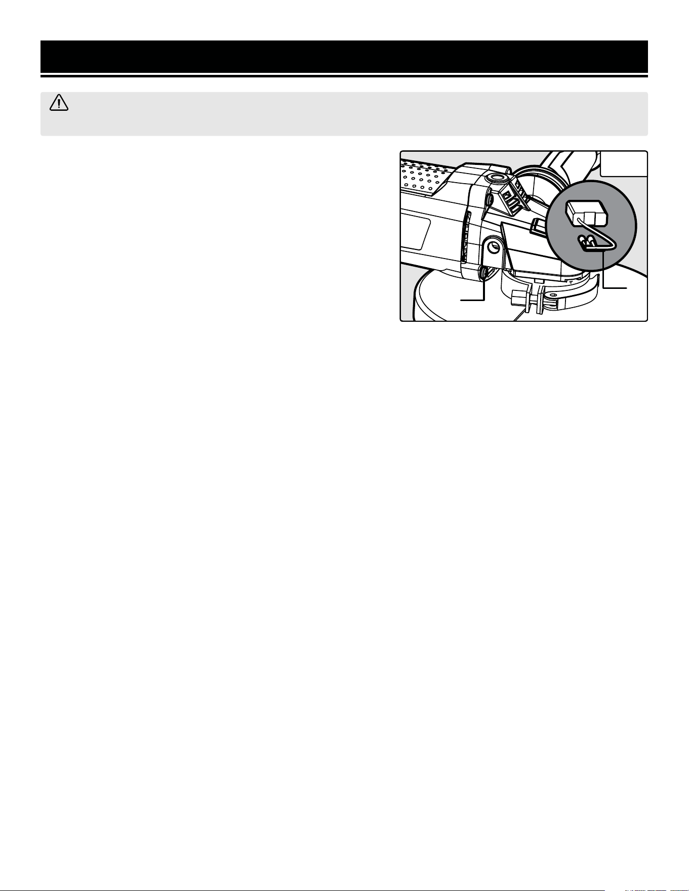
spindle lock (Fig. 3 - 1) to keep the spindle from rotating.
WARNING! To avoid injury from accidental startups, make sure that the tool is OFF and removed from the
power supply when assembling the tool or when making any adjustments.
Fig. 2
Fig. 3
4
3
2
1
5
1
11
ASSEMBLY & ADJUSTMENTS
INSTALLING THE AUXILIARY HANDLE
The auxiliary handle can be installed in one of three different posi-
tions: The left side of the housing, the right side of the housing,
or on top of the housing.
1. Screw the threaded end of the auxiliary handle (Fig. 4 - 1) into
the desired mounting hole. Make sure that the auxiliary handle is
secure before beginning operation.
ADJUSTING THE GRINDING ANGLE
The head of your angle grinder can be adjusted to three different
angles for different operations: 0º, 90º Left, or 90º Right.
1. Press the angle adjustment lock (Fig. 5 - 1) to unlock the ad-
justable head.
2. Rotate the angle grinder head (Fig. 5 - 2) left or right until the
indication arrow on the head aligns with one of the three indica-
tion arrows on the body. The angle grinder head will lock in place.
Make sure that the angle grinder head is secure before beginning
operation.
WARNING! To avoid injury from accidental startups, make sure that the tool is OFF and removed from the
power supply when assembling the tool or when making any adjustments.
Fig. 4
1
WARNING! DO NOT TURN THE ANGLE GRINDER ON OR
OFF WHILE THE TOOL IS UNDER LOAD; this will greatly de-
crease the life of the tool.
OPERATION
TURNING THE TOOL ON & OFF
1. Plug the tool into the power supply.
2. To turn the tool ON, push the trigger lock (Fig. 6 - 1) forward.
With the trigger lock pushed forward, press the power trigger
(Fig. 6 - 2).
Fig. 6
2
1
Fig. 5
1
2
3. To turn the tool OFF, release the power trigger and push the trigger lock backward to lock the power trigger in the
OFF position.
4. Once operation has been completed, unplug the tool from the power supply.
Always hold the tool with both hands since the torque from the motor can cause the grinder to twist. Start the angle
grinder before applying it to the workpiece. Allow the disc to reach full speed before making contact with the work-
piece. Lift the tool from the workpiece before turning the machine OFF.

12
OPERATION
SELECTING THE GRINDING DISC
Before using a grinding wheel, make sure that its maximum safe operating speed is more than 8,500 RPM. Do not
exceed the recommended wheel diameter. Make sure it has a threaded 5/8”-11 arbor, or an unthreaded 7/8” arbor
to fit the supplied inner flange.
Grinding wheels should be carefully selected in order to maximize efficiency. Wheels vary in abrasiveness, bond,
harness, grit size and structure. The correct type of wheel to use is determined by the job at hand. Use disc grinding
wheels for fast grinding of structural steel, heavy weld beads, steel casting, stainless steel and other ferrous metals.
GRINDING TIPS
Efficient grinding is achieved by controlling the pressure and keeping the angle between the wheel and the work-
piece between 15° to 30°. If the wheel is flat, the tool will be difficult to control. If the angle is too steep, the pressure
concentrated on a small area can cause burning to the work surface.
WARNING! - Excessive or sudden pressure on the wheel will slow the grinding action and put dangerous stresses
on the wheel.
When grinding with a new wheel, be sure to grind while pulling the tool backwards until the wheel becomes rounded
on its edge. New wheels have sharp corners which tend to “bite” or cut into the workpiece when pushing forward.
WARNING! Excessive or sudden pressure on the wheel will slow the grinding action and put dangerous
stresses on the wheel.
MAINTENANCE
REPLACING THE CARBON BRUSHES
To maintain maximum efficiency of the motor, we recommend
changing the carbon brushes every 50 hours of operation. Re-
placement carbon brushes (part no. 94487-038) are available at
wenproducts.com. Only genuine WEN replacement brushes de-
signed specifically for your tool should be used.
Your angle grinder comes with one pair of replacement carbon
brushes.
To inspect or replace the carbon brushes:
1. Loosen the four gear box housing screws (Fig. 6 - 1) and re-
move the gear box housing.
2. When removing the carbon brushes (Fig. 6 - 2), take note of
their orientation. The new carbon brushes will need to be installed
in the same orientation.
NOTE: Both carbon brushes should be replaced at the same time.
3. Install the new carbon brushes and replace the gear box hous-
ing cover.
4. Once the new carbon brushes have been installed, run the
angle grinder to make sure that the brushes have been installed
correctly.
NOTE: It is normal for new carbon brushes to spark a bit as they
wear in.
PRODUCT DISPOSAL
Used power tools should not be disposed of together with house-
hold waste. This product contains electronic components that
should be recycled. Please take this product to your local recy-
cling facility for responsible disposal and to minimize its environ-
mental impact.
WARNING! To avoid accidents, make sure the tool is OFF and removed from the power supply before
cleaning or performing any maintenance. Servicing of the tool must be performed by a qualified technician.
13
Fig. 6
1
2
ROUTINE INSPECTION
1. Before each use, inspect the general condi-
tion of the tool.
Check for:
• Loose hardware
• Misalignment or binding of moving parts
• Damaged cord/electrical wiring
• Cracked or broken parts
• Any other condition that may affect its safe
operation
2. After every use, wipe the tool with a soft
cloth. Do not let water enter the tool.
3. Keep the ventilation openings and power
switch free from dust and debris to prevent the
motor from overheating or switch from failing.
Blow the tool off using compressed air (not to
exceed 25 PSI) after every use.
4. Most plastics are susceptible to damage
from various types of commercial solvents. Do
not use any solvents or cleaning products that
could damage the plastic parts. Some of these
include but are not limited to: gasoline, carbon
tetrachloride, chlorinated cleaning solvents,
ammonia and household detergents that con-
tain ammonia.
5. Store the tool in a clean and dry place away
from the reach of children.
14
NOTE: Not all parts may be available for purchase. Parts and accessories that wear down over the course of
normal use are not covered under the warranty.
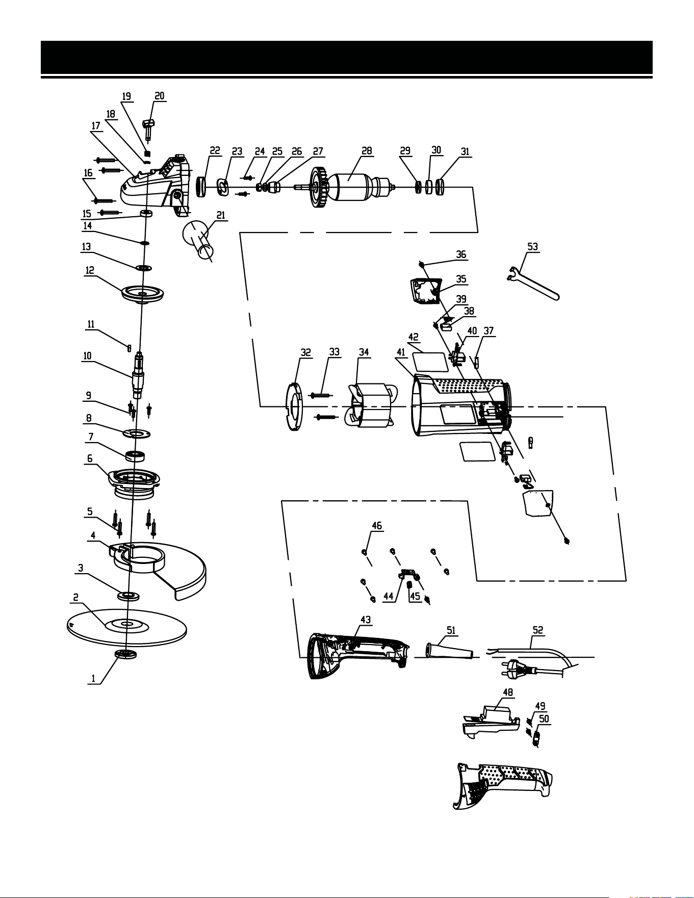
EXPLODED VIEW & PARTS LIST

EXPLODED VIEW & PARTS LIST
No. Part No. Description Qty.
1 94487-001 Outer Flange 1
2 94487-002 Grinding Disc 1
3 94487-003 Inner Flange 1
4 94487-004
Wheel Guard
Assembly
1
5 94487-005 Screw M5x16 4
6 94487-006 Gearing Cover 1
7 94487-007 Bearing 6202 1
8 94487-008 Bearing Cover 1
9 94487-009 Screw M4x10 3
10 94487-010 Spindle 1
11 94487-011 Half Key (4x13) 1
12 94487-012 Large Gear 1
13 94487-013 Wave Washer 1
14 94487-014 Spring Washer 1
15 94487-015 Bearing 608 1
16 94487-016 Screw ST4.8x30 4
17 94487-017 Gear Box Housing 1
18 94487-018 Circlip 1
19 94487-019 Spring 1
20 94487-020 Spindle Lock 1
21 94487-021 Side Handle 1
22 94487-022 Bearing 6001 1
23 94487-023 Bearing Cover 1
24 94487-024 Screw M4x10 2
25 94487-025 Locknut M8 1
26 94487-026 Spring Washer 1
No. Part No. Description Qty.
27 94487-027 Pinion 1
28 94487-028 Rotor 1
29 94487-029 Bearing 608 1
30 94487-030 Bearing Cover 1
31 94487-031 Bearing Seat 1
32 94487-032 Wind Shield 1
33 94487-033 Screw ST 3.9x60 2
34 94487-034 Stator 1
35 94487-035 Brush Cover 2
36 94487-036 Screw ST 3.9X16 2
37 94487-037 Spring 2
38 94487-038 Carbon Brush 2
39 94487-039 Screw ST 3.9X16 2
40 94487-040 Brush Holder 2
40 94487-041 Screw M4x8 2
41 94487-042 Housing 1
42 94487-043 Label 2
43 94487-044 Bottom Handle 1
44 94487-045
Handle Rotation
Button
1
45 94487-046
Spring φ0.8
1
46 94487-047 Screw ST 3.9x16 5
47 94487-048 Switch 1
48 94487-049 Screw ST 3.9x16 2
49 94487-050 Cable Holder 1
50 94487-051 Cable Sleeve 1
51 94487-052 Cable 1
52 94487-053 Wrench 1
NOTE: Not all parts may be available for purchase. Parts and accessories that wear down over the course of
normal use are not covered under the warranty.
15

WARRANTY STATEMENT
WEN Products is committed to building tools that are dependable for years. Our warranties are consistent with this
commitment and our dedication to qualit
y.
LIMITED WARRANTY OF WEN PRODUCTS FOR HOME USE
GRE
AT LAKES TECHNOLOGIES, LLC (“Seller”) warrants to the original purchaser only, that all WEN
consumer
power tools will be free from defects in material or workmanship during personal use for a period of two (2) years
used
for professional or commercial use. Purchaser has 30 days from the date of purchase to report missing or
damaged parts.
SELLER’S
SOLE OBLIGATION AND YOUR EXCLUSIVE REMEDY under this Limited Warranty and, to the extent per-
mitted
by law, any warranty or condition implied by law, shall be the replacement of parts, without charge, which a
re
defective
in material or workmanship and which have not been subjected to misuse, alteration, careless handling,
misrepair
, abuse, neglect, normal wear and tear,
improper maintenance, or other conditions adversely affecting the
Product
or the component of the Product, whether by accident or intentionally, by persons other than Seller. To
make
a claim under this Limited Warranty, you must make sure to keep a copy of your proof of purchase that
clearly
-
dor
of Great Lakes Technologies, LLC. Purchasing through third party vendors, including but not limited to garage
sales,
pawn shops, resale shops, or any other secondhand merchant, voids the warranty included with this
product.
Contact [email protected] or 1-847-429-9263 with the following information to make arrangements:
your
shipping address, phone number, serial number, required part numbers, and proof of purchase. Damaged
or
defective parts and products may need to be sent to WEN before the replacements can be shipped out.
-
turning
a product for warranty service, the shipping charges must be prepaid by the purchaser. The product
must
be
shipped in its original container (or an equivalent), properly packed to withstand the hazards of shipment. The
product
must be fully insured with a copy of the proof of purchase enclosed. There must also be a description of
the
will be returned and shipped back to the pur
chaser at no charge for addresses within the contiguous United States.
THIS
LIMITED WARRANTY DOES NOT APPLY TO ITEMS THAT WEAR OUT FROM REGULAR USAGE OVER TIME,
INCLUDING
BELTS, BRUSHES, BLADES, BATTERIES, ETC. ANY IMPLIED WARRANTIES SHALL BE LIMITED IN
DUR
ATION TO TWO (2) YEARS FROM DATE OF PURCHASE. SOME STATES IN THE U.S. AND SOME CANADIAN
PROVINCES
DO NOT ALLOW LIMITATIONS ON HOW LONG AN IMPLIED WARRANTY LASTS, SO THE ABOVE LIMI-
TAT
ION MAY NOT APPLY TO YOU.
IN
NO EVENT SHALL SELLER BE LIABLE FOR ANY INCIDENTAL OR CONSEQUENTIAL DAMAGES (INCLUDING
BUT
NOT LIMITED TO LIABILITY FOR LOSS OF PROFITS) ARISING FROM THE SALE OR USE OF THIS PRODUCT.
SOME ST
ATES IN THE U.S. AND SOME CANADIAN PROVINCES DO NOT ALLOW THE EXCLUSION OR LIMITAT
ION
OF
INCIDENTAL OR CONSEQUENTIAL DAMAGES, SO THE ABOVE LIMITATION OR EXCLUSION MAY NOT APPLY
TO YOU.
THIS
LIMITED WARRANTY GIVES YOU SPECIFIC LEGAL RIGHTS, AND YOU MAY ALSO HAVE OTHER RIGHTS
WHICH
VARY FROM STATE TO STATE IN THE U.S., PROVINCE TO PROVINCE IN CANADA AND FROM COUNTRY
TO COUNT
RY.
THIS
LIMITED WARRANTY APPLIES ONLY TO ITEMS SOLD WITHIN THE UNITED STATES OF AMERICA, CANA-
DA
AND THE COMMONWEALTH OF PUERTO RICO. FOR WARRANTY COVERAGE WITHIN OTHER
COUNTRIES,
CONT
ACT THE WEN CUSTOMER SUPPORT LINE. FOR WARRANTY PARTS OR PRODUCTS REPAIRED UNDER
W
ARRANTY SHIPPING TO ADDRESSES OUTSIDE OF THE CONTIGUOUS UNITED STATES, ADDITIONAL
SHIPPING
CHARGES MAY APPLY.
V. 2024.09.18
16