© SIMPLIPHI POWER, INC.
SIMPLIPHIPOWER.COM | 805-640-6700 | BSREV202111121120
1
MODEL NO. 052000
Installaon Manual
PHI 3.8-M
TM
Baery Module
PHI 3.8-M
TM
Not for reproduction
© SIMPLIPHI POWER, INC.
SIMPLIPHIPOWER.COM | 805-640-6700 | BSREV202111121120
2
MODEL NO. 052000
SimpliPhi Your Energy
Security and Independence
and gain control of your own power.
SimpliPhi Power helps you manage your power as a personal resource.
Anytime. Anywhere. SimpliPhi energy storage optimizes integration of any
power generation source – solar, wind, generator – on or off grid, and protects
your home and mission-critical business functions from power outages and
intermittency. SimpliPhi storage technology reduces operating temperature
constraints, toxic coolants and the risk of thermal runaway. Safe lithium ferrous
phosphate (LFP). No cobalt. No toxic hazards.
SimpliPhi’s battery technology utilizes the industry’s most environmentally benign
chemistry (LFP) combined with proprietary architecture and power electronics
(BMS) to create a portfolio of high performance, scalable and enduring energy
storage solutions that provide power security, resilience and daily cycling for
savings on your utility bill – all with a 98% efficiency rate.
SimpliPhi Power offers proprietary, commercially available energy storage and
management systems that are safe, non-toxic, reliable, durable, efficient, highly
scalable, and economical over the lifetime of the PHI Battery.
Not for reproduction

© SIMPLIPHI POWER, INC.
SIMPLIPHIPOWER.COM | 805-640-6700 | BSREV202111121120
3
MODEL NO. 052000
Table of Contents
1.0 – Introducon .................................................................................................................................................................................. 6
1.1 – Online Resources ..................................................................................................................................................................... 6
1.2 – Technical Support .................................................................................................................................................................... 6
1.3 – Product Overview .................................................................................................................................................................... 6
1.3.1 – Baery Management System (BMS) ............................................................................................................................ 6
1.3.2 – Built-In Breaker ................................................................................................................................................................. 7
1.4 – Specicaons ............................................................................................................................................................................ 8
2.0 – Safety ............................................................................................................................................................................................. 9
2.1 – General Safety Instrucons ................................................................................................................................................... 9
2.2 – Response to Emergency Situaons ..................................................................................................................................... 9
3.0 – Pre-Installaon ............................................................................................................................................................................. 10
3.1 – PHI Baery Performance ....................................................................................................................................................... 10
3.2 – PHI Baery System Sizing ..................................................................................................................................................... 10
3.2.1 – Sizing for Maximum Instantaneous Discharge (Load Rate) ..................................................................................... 10
3.2.2 – Sizing for Maximum Instantaneous Charge Rate (DC Coupled) ............................................................................ 11
3.2.3 – Sizing for Maximum Instantaneous Charge Rate (AC Coupled) ............................................................................. 12
3.2.4 – Overall Baery System Sizing ....................................................................................................................................... 12
4.0 – Installaon ..................................................................................................................................................................................... 13
4.1 – Installaon Opons ................................................................................................................................................................. 13
4.2 – Environmental Consideraons .............................................................................................................................................. 13
4.2.1 – Charging at Temperatures Below Freezing ................................................................................................................. 13
4.2.2 – Explosive Gas Precauons ............................................................................................................................................. 13
4.2.3 – An-Corrosion Protecon .............................................................................................................................................. 13
4.3 – Mounng Hardware ................................................................................................................................................................ 14
4.4 – Dimensions and Weight ......................................................................................................................................................... 14
4.5 – PHI Baery Connecon Terminals ....................................................................................................................................... 15
4.5.1 – Baeries with Threaded Studs ...................................................................................................................................... 15
4.5.2 – Torque Value for Baeries with Threaded Studs ....................................................................................................... 15
4.6 – Wiring ......................................................................................................................................................................................... 16
4.6.1 – Increasing Storage Capacity via Parallel Wiring ......................................................................................................... 16
4.6.2 – Parallel Wiring Baeries with Threaded Studs using Baery Cables .................................................................... 16
Helpful Tips: ..................................................................................................................................................................................... 18
4.6.3 – Parallel Wiring Baeries with Threaded Studs using Interconnecng Busbars .................................................. 20
4.7 – Baery System Commissioning ............................................................................................................................................ 21
4.8 – Baery Bank Expansion ......................................................................................................................................................... 24
5.0 – Programming ................................................................................................................................................................................ 25
5.1 – Operang Parameters Related to Cycle Life ..................................................................................................................... 25
6.0 – Troubleshoong ........................................................................................................................................................................... 26
Appendix A – PHI Baery Safety & Green Aributes, Cercaons ......................................................................................... 28
Appendix B – PHI Baery Bank Sizing Guide .................................................................................................................................. 30
Appendix C – PHI Approved External Chargers ............................................................................................................................ 32
Not for reproduction

© SIMPLIPHI POWER, INC.
SIMPLIPHIPOWER.COM | 805-640-6700 | BSREV202111121120
4
MODEL NO. 052000
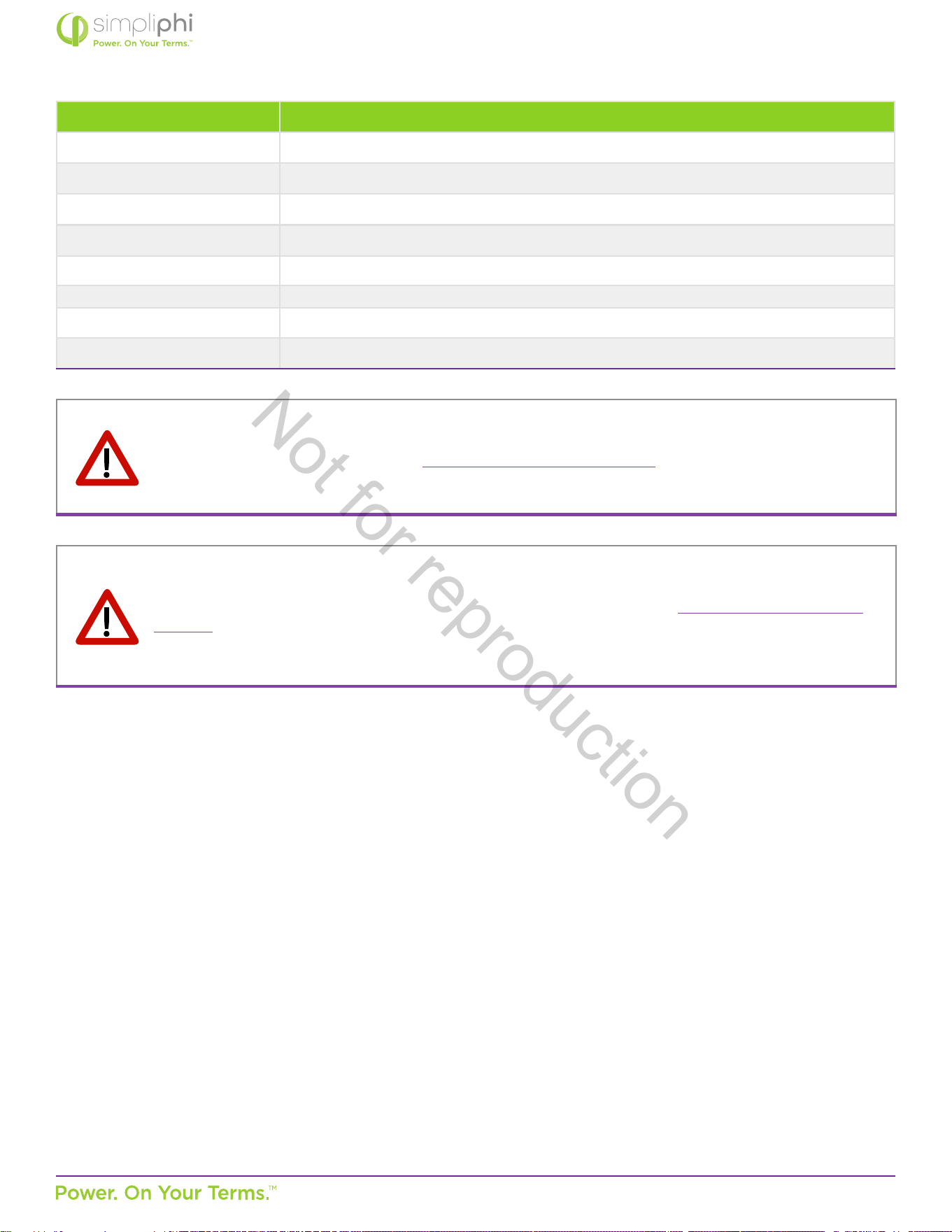
The following abbreviated guidelines do NOT encompass all PHI baery Warranty details. Failure to adhere to the Warranty
and Installaon Manual requirements will Void the Warranty. Read the baery’s complete Warranty prior to installaon and
register the baery according to the form found at the boom of the same web page address: hps://simpliphipower.com/wp-
content/uploads/documentaon/ampliphi-series-phi-series/simpliphi-power-ampliphi-baery-phi-baery-warranty.pdf
CAUTION: The following will result in damage to your PHI baeries and will Void the Warranty:
1. Incorrect baery wiring and/or installaon
A. Verify polarity at all connecons with a standard voltmeter (1) before energizing the system and (2) on baeries with
threaded stud connecons, before switching the built-in circuit breaker to the “ON” posion. Reverse polarity at the
PHI Baery terminals will Void the Warranty and destroy the PHI Baeries.
B. PHI Baeries must be fully charged before commissioning (i.e. before connecng loads). Failure to do so will damage
the PHI baeries and Void the Warranty.
C. Lugs, washers and lug nuts must be installed according to the Installaon Manual. Failure to do so will damage the PHI
Baeries and Void the Warranty.
2. Charging the baery in sub-freezing temperatures.
3. Pairing the baery with incompable equipment. Use of accessories not recommended or sold by the manufacturer may
result in a risk of re, electric shock, or injury to persons and will Void the Warranty.
A. Contact SimpliPhi Technical Support at (805) 640-6700 x 1 regarding the compability of any equipment not explicitly
listed in the ‘Integraon Guides’ secon of the Product Documentaon web page (hps://simpliphipower.com/product-
documentaon/).
B. Refer to the SimpliPhi-Approved Chargers list (Appendix C of this document) for all compable external / plug-in
baery chargers. Use only a SimpliPhi-approved LFP baery charger if ancillary charging is required before installaon,
tesng or troubleshoong. Failure to use a SimpliPhi-approved LFP baery charger will damage the PHI Baery and
Void the Warranty.
4. Incorrect inverter and/or charge controller sengs. Operang the PHI Baery in conjuncon with equipment not
programmed to the PHI Baery’s sengs will Void the Warranty.
A. Refer to the ‘Integraon Guides’ secon of the Product Documentaon web page (hps://simpliphipower.com/product-
documentaon/) for all inverter and charge controller sengs.
B. Although each PHI Baery contains an internal Baery Management System (BMS) with circuitry that protects the PHI
Baery cells from over-charge, over-discharge and extreme load amperage, the PHI Baery must always be installed
with appropriate inverter and/or charge controller sengs and power electronics to protect the PHI Baery from open
solar photovoltaic (PV) voltage and other high voltage charging sources.
C. Failure to protect the PHI baeries from voltages higher than the baery voltage rang will destroy the PHI baeries,
cause electrical res and Void the Warranty.
5. Incorrect baery bank sizing.
A. Exceeding the PHI baeries’ maximum connuous discharge rate or charge rate destroys the PHI baeries and will
Void the Warranty.
B. Refer to Secon 3.2 and Appendix B of this Manual for more informaon on how to accurately and correctly calculate
the PHI baery bank capacity. Failure to do so will destroy the PHI baeries and Void the Warranty.
CAUTION: THESE 5 THINGS WILL VOID THE PHI WARRANTY & DAMAGE THE BATTERIES.
READ IN FULL PRIOR TO BATTERY INSTALLATION
Not for reproduction

© SIMPLIPHI POWER, INC.
SIMPLIPHIPOWER.COM | 805-640-6700 | BSREV202111121120
5
MODEL NO. 052000
MISE EN GARDE: LES CINQ POINTS CI-DESSOUS ANNULERONT VOTRE GARANTIE PHI ET
ENDOMMAGERONT LES BATTERIES. LIRE L’INTÉGRALITÉ DE CE DOCUMENT AVANT L’INSTALLATION.
Les instrucons abrégées suivantes ne couvrent PAS tous les détails de la Garane des baeries PHI.
Ne pas tenir compte des exigences du Manuel de Garane et du Manuel d’Installaon Annulera la Garane.
Lire l’intégralité de ce document ainsi que le Manuel de Garane de la baerie avant l’installaon.
Enregistrez votre baerie PHI en ulisant le formulaire en bas de page du document en cliquant sur le lien ci-dessous. hps://
simpliphipower.com/wp-content/uploads/documentaon/ampliphi-series-phi-series/simpliphi-power-ampliphi-baery-phi-
baery-warranty.pdf
MISE EN GARDE: Ce qui suit entraînera des dommages irréversibles à votre baerie et Annulera sa Garane.
1. Un mauvais câblage et/ou une mauvaise installaon de la baerie
A. Vérier la polarité de tous les branchements à l’aide d’un voltmètre standard (1) avant de mere le système sous tension
et (2) sur les baeries munies de goujons letés, avant de mere le disjoncteur intégré en posion « ON ». Une polarité
inversée aux bornes de la Baerie PHI Annulera la Garane et détruira les Baeries PHI.
B. Les Baeries PHI doivent être complètement chargées individuellement avant la mise en service (c.-à-d. avant de
connecter les charges). Ne pas suivre ces instrucons entraînera l’endommagement des baerie et l’Annulaon de la
Garane.
C. Les cosses, les rondelles et les écrous doivent être installés conformément au Manuel d’Installaon. Ne pas suivre ces
instrucons entraînera l’endommagement des baerie et l’Annulaon de la Garane.
2. Un chargement de la baerie en dessous 0°C (32° F).
3. Une ulisaon de la baerie avec un équipement incompable. L’ulisaon d’accessoires non approuvés ou non vendus
par le fabricant peut entraîner un risque d’incendie, de choc électrique ou de blessures pour les personnes et Annulera la
Garane.
A. Contactez le Support Technique de SimpliPhi au (805) 640-6700 x 1 pour vérier la compabilité de tout équipement
ou accessoires qui ne sont pas listés dans la secon « Guides d’Intégraon » de la page internet de la Documentaon
Produit. (hps://simpliphipower.com/product-documentaon/).
B. Se reporter à la liste des Chargeurs Approuvés par Simpliphi (Annexe C du présent document) pour tous les chargeurs
de baerie externes / à connecteurs compables. Uliser uniquement un chargeur de baerie LFP approuvé par
Simpliphi si une charge auxiliaire est nécessaire avant l’installaon, la mise à l’essai ou le dépannage. Ne pas uliser un
chargeur de baerie LFP approuvé par Simpliphi endommagera la Baerie PHI et Annulera la Garane.
4. Un réglage incorrect de l’onduleur et/ou du contrôleur de charge. L’ulisaon de la Baerie PHI en conjoncon avec un
équipement non programmé selon les paramètres de la Baerie PHI Annulera la Garane.
A. Reportez-vous à la secon « Guides d’intégraon » de la page internet de la Documentaon Produit. (hps://
simpliphipower.com/product-documentaon/)
B. Chaque Baerie PHI conent un système de geson interne (BMS) qui protègent les cellules de la Baerie PHI contre
une surcharge, une décharge excessive et un ampérage trop fort . Cependant la Baerie PHI doit toujours être installée
avec les réglages appropriés de l’onduleur et/ou du régulateur de charge et de l’alimentaon électronique pour protéger
la Baerie PHI d’une charge photovoltaïque (PV) à haute tension ou toute autre source à haute tension.
C. Le fait de ne pas protéger les baeries PHI contre des tensions supérieures à la tension nominale de la baerie détruira
les Baeries PHI, provoquera des incendies électriques et Annulera la Garane.
5. Un mauvais dimensionnement du groupe de baeries.
A. Un dépassement du taux de décharge ou de charge maximal des Baeries PHI détruira les Baeries PHI et Annulera la
Garane.
B. Se reporter à la Secon 3.2 et à l’Annexe B du présent Manuel pour plus d’informaons sur la façon de calculer avec
précision et correctement la capacité du groupe de baeries PHI. Ne pas suivre ces instrucons détruira les baeries
Not for reproduction
© SIMPLIPHI POWER, INC.
SIMPLIPHIPOWER.COM | 805-640-6700 | BSREV202111121120
6
MODEL NO. 052000
MISE EN GARDE: Chaque Baerie PHI conent un système de geson interne (BMS) qui protègent les
cellules de Baerie PHI contre une surcharge, une décharge excessive et ampérage trop fort. Cependant les
baeries PHI doivent toujours être installées avec les réglages appropriés de l’onduleur et/ou du contrôleur
de charge pour protéger la Baerie PHI contre une charge photovoltaïque (PV) à haute tension ou toute
autre source à haute tension. Une exposion à une tension supérieure à la tension nominale de la Baerie
PHI détruira les baeries PHI et Annulera la Garane.
The PHI Baery Warranty does NOT cover product damage caused by mishandling or improper use per the Installaon Manual,
Integraon Guides and Warranty, exposure to liquids, impacts from falling objects or being dropped, or aempts to repair the
baery by any party other than SimpliPhi. The complete list of Warranty Exclusions is included in the PHI Baery Warranty
document: hps://simpliphipower.com/wp-content/uploads/documentaon/ampliphi-series-phi-series/simpliphi-power-
ampliphi-baery-phi-baery-warranty.pdf
1.0 – Introducon
1.1 – Online Resources
The Product Documentaon secon of SimpliPhi’s web site (hps://simpliphipower.com/product-documentaon/) includes
Specicaon Sheets, Warranes, Installaon & Operator’s Manuals, and Integraon Guides for all SimpliPhi’s current products.
For informaon regarding legacy products see Appendix D for baery parameters or contact techsupport@simpliphipower.com.
SimpliPhi’s YouTube channel (hps://www.youtube.com/channel/UCcuCaLT_G3Hhumteh-pI5yg/videos) has instruconal
videos showing various steps of the baery installaon process in detail.
1.2 – Technical Support
SimpliPhi Technical Support (805-640-6700 x 1, techsupport@simpliphipower.com) is available to take any quesons
regarding this manual or general installaon quesons. For assistance with baery system commissioning, SimpliPhi asks that a
commissioning call be scheduled ahead of me with Technical Support.
We encourage you or your installer to contact SimpliPhi with any quesons. We are commied to working with you and your
installaon team to achieve a safe, reliable storage system that will provide years of maintenance-free service that is covered by
our Warranty terms & condions.
1.3 – Product Overview
The PHI deep-cycle Lithium Ferro Phosphate (LFP) Baery is opmized with proprietary cell architecture, power electronics,
Baery Management System (BMS), manufacturing materials and processes. This assures the highest grade and quality, longest
cycle-life, greatest eciency and freedom from material impuries, toxicity and hazardous risk. The PHI Baery is modular,
lightweight and scalable. It provides power security and seamless integraon of renewable and tradional sources of energy in
conjuncon with or independent of the grid.
1.3.1 – Baery Management System (BMS)
Each PHI Baery contains circuitry that protects the LFP cells from overcharge, over-discharge and extreme load amperage.
If pre-programmed BMS values are exceeded, the protecve circuitry will shut down the ow of electricity to/from the PHI
Baeries. In some cases, this will result in the need to re-set the BMS (see Secon 6.0 - Troubleshoong of this Manual)
and re-inialize an inverter/charger. Oen, inverter system sengs will be saved within the inverter memory storage and
will not need to be reset. However, this is not an absolute standard but is common in most inverter/chargers and should be
ancipated if the PHI Baeries go into a state of self-protecon and shut down the ow of electricity. Refer to SimpliPhi’s
Integraon Guides for inverter and/or charge controller sengs (hps://simpliphipower.com/product-documentaon/).
CAUTION: Although each PHI Baery contains an internal BMS with circuitry that protects the PHI Baery
cells from over-charge, over-discharge and extreme load amperage, the PHI Baeries must always be
installed with appropriate inverter and/or charge controller sengs to protect the PHI Baery from open PV
voltage and other high voltage charging sources. Exposure to higher voltage than the PHI baery rang will
destroy the PHI baeries and Void the Warranty.
Not for reproduction
© SIMPLIPHI POWER, INC.
SIMPLIPHIPOWER.COM | 805-640-6700 | BSREV202111121120
7
MODEL NO. 052000
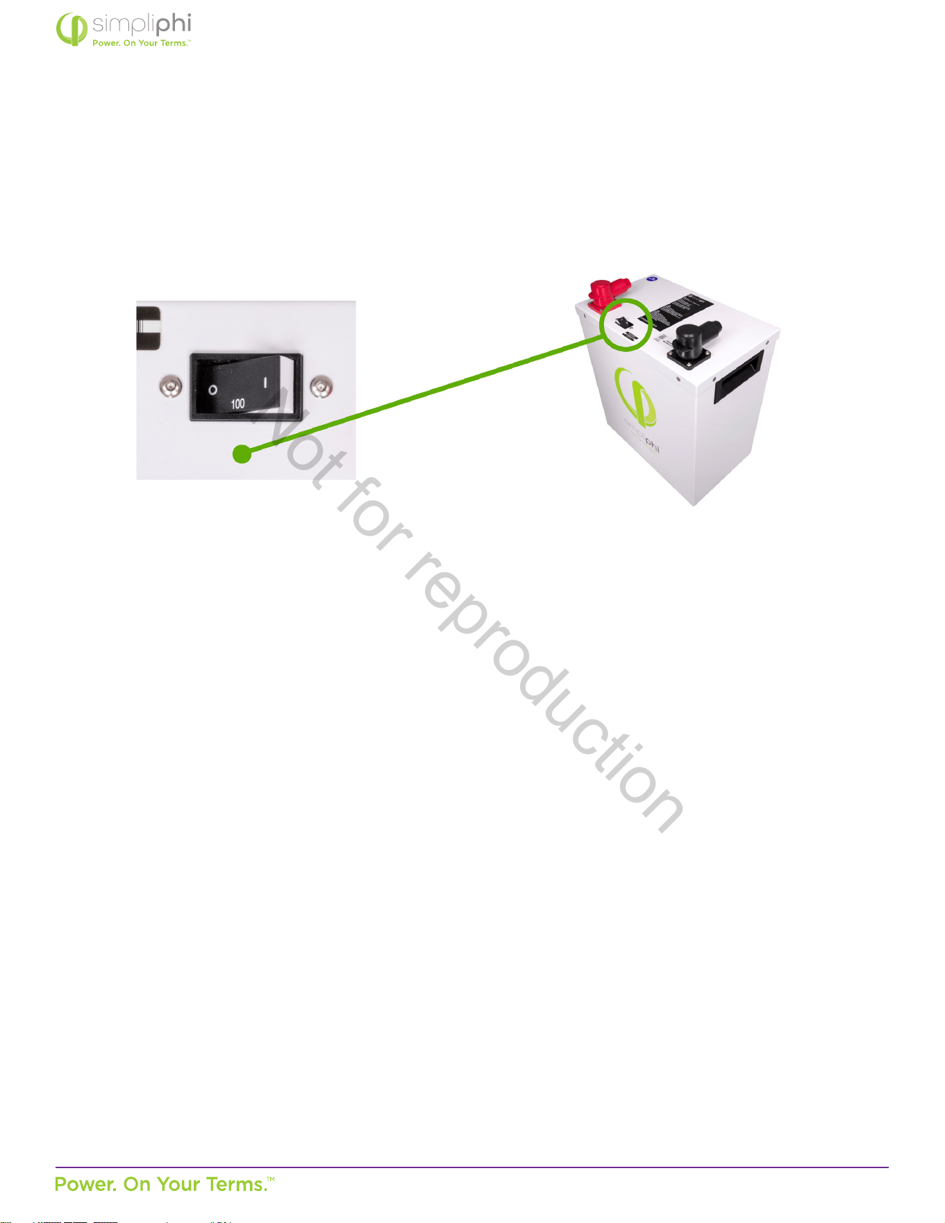
1.3.2 – Built-In Breaker
PHI baeries with threaded stud connecons (such as baery models PHI 3.8-M) are outed with a hydraulic/magnec
circuit breaker. This breaker increases safety during shipping and installaons and allows the baery to eecvely be turned
“OFF” or “ON.” The breaker works in conjuncon with the baery’s built-in BMS and creates addional safety, eciency and
funconality in the overall power storage system.
Figure 1.0 – PHI 3.8 Circuit Breaker
NOTE: Circuit breakers, disconnects and fuses should be employed throughout several points of a power storage and
generaon installaon to eecvely isolate and protect all components of the system to safeguard against faults, short
circuits, polarity reversals or a failure of any component in the overall system. Fuses, breakers, wiring rangs and values
should be determined by established electrical codes and standards and evaluated by cered electricians, licensed
installers, and regional code authories.
Not for reproduction
© SIMPLIPHI POWER, INC.
SIMPLIPHIPOWER.COM | 805-640-6700 | BSREV202111121120
8
MODEL NO. 052000
PHI 3.8-M
TM
48V
DC Voltages - Nominal 51.2 VDC
Amp-Hours 75 Ah
Rated Capacity 3.8 kWh DC
MAX Discharge Rate
(10 minutes)
80 Amps DC
(4.1 kW DC)
MAX Connuous
Discharge & Charge
Rate
37.5 Amps DC
(1.92 kW DC)
DC Voltage Range
1
48 to 56 VDC
Depth of Discharge
1
up to 100%
Operang Eciency 98%
Charging Temperature
1
32° to 120° F (0° to 49° C)
Operang Temperature
1
-4° to 140° F (-20° to 60° C)
Storage Temperature
6 months: 14° to 77° F (-10° to 25° C)
3 months: -4° to 113° F (-20° to 45° C)
Self-Discharge Rate < 1% per month
Expected Cycle Life 10,000 cycles @ 80% DOD / 5,000 cycles @ 90% DOD / 3,500 cycles @ 100% DOD
Memory Eect None
Warranty Period 10 Years
Weight 86 lbs (39 kg)
2
Dimensions (W x H x D)
13.5 x 14 x 8 in.
(15.5” H w/terminals) / 0.88
3
(34.3 x 35.6 x 20.3 cm / 0.025 m
3
)
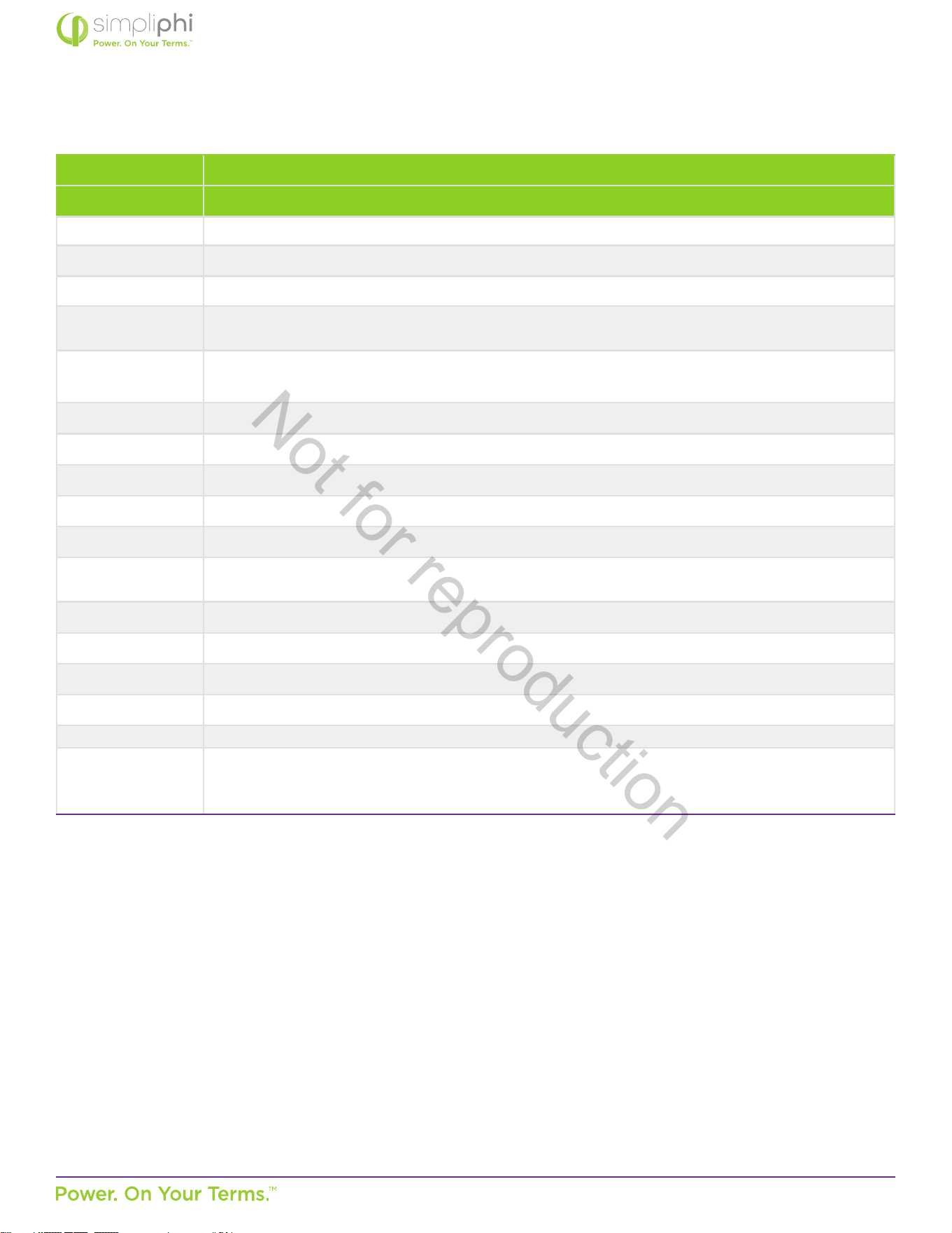
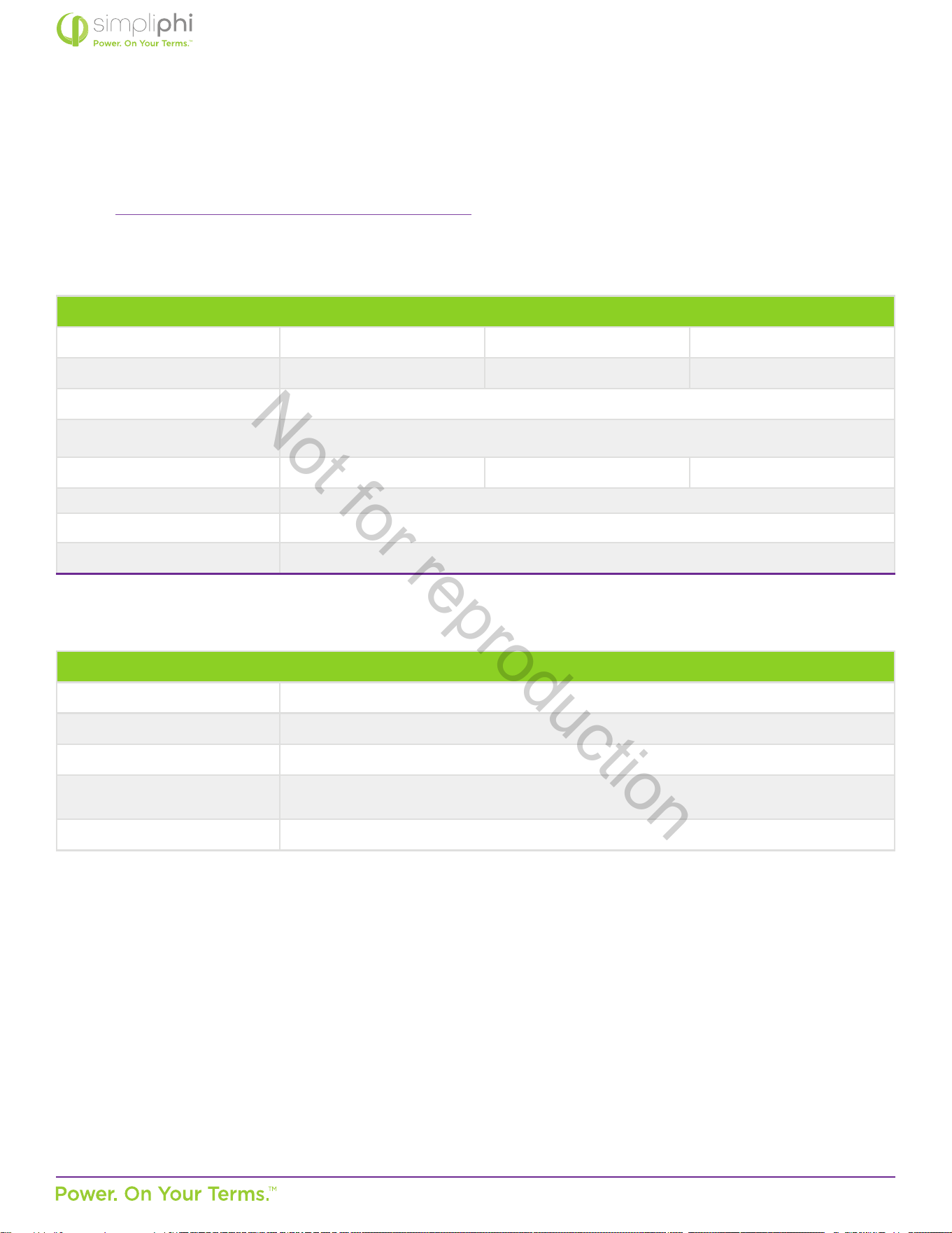
1.4 – Specicaons
Please review Table 1.0 below for PHI Baery specicaons, including physical dimensions, Warranty period, and technical data.
Table 1.0 - PHI Baery Specicaons
Notes:
1
Max operang ranges. Refer to Warranty for recommended condions.
• Specicaons are typical/nominal. Subject to change without noce.
• There is less than 1% loss of energy during charging.
Not for reproduction
© SIMPLIPHI POWER, INC.
SIMPLIPHIPOWER.COM | 805-640-6700 | BSREV202111121120
9
MODEL NO. 052000
2.0 – Safety
For safety reasons, read all instrucons and cauonary markings on the PHI Baeries, and all appropriate secons of this
manual. Failure to follow instrucons provided in the Installaon Manual, Integraon Guides and Warranty will Void the
Warranty.
2.1 – General Safety Instrucons
• Do not operate if the PHI Baery has been damaged in any way during shipping or otherwise.
• To reduce the chance of short-circuits, always use insulated tools when installing or working with PHI baeries or other
electrical equipment.
• Remove personal metal items such as rings, bracelets, necklaces, and watches when working with PHI baeries and electrical
equipment. Wear insulated gloves and rubber shoes.
• PHI Baeries pose some risk of shock or sparking during the installaon and inial wiring and connecon process. This is
consistent with all other baery-based storage formats. For baeries with threaded stud connecons, be sure the built-in
breaker is in the “OFF” posion to minimalize the risk of shock or sparks during the installaon and commissioning of the
system.
• To avoid a risk of re and electric shock, make sure that exisng system wiring is in good condion and that the wire is not
undersized. Do not operate the PHI Baery in conjuncon with damaged or substandard wiring.
These safety precauons are in addion to the Warnings previously outlined on page 4 of this Manual.
2.2 – Response to Emergency Situaons
As with any baery, if the PHI Baery’s cells are severely damaged due to physical abuse, reverse polarity, high voltage,
unmigated current or other electrical phenomenon incurred outside of Warranted specicaons, it can cause electrolyte
leakage and other failures. The electrolyte can be ignited by an open external ame. However, unlike other lithium ion baeries
with cobalt oxides (e.g. LCO, NCM and NCA), the PHI LFP Baeries’ electrolyte and other material components generate a
limited amount of heat and do not go into a state of thermal runaway with re propagaon. The SimpliPhi UL 1973 Baery
Cercaon veries “No Thermal Runaway” (see MSDS for chemical analyses).
While PHI Baeries do not go into thermal runaway with re propagaon, the following protocol should be followed in the event
that the PHI baeries are subjected to electrical re caused by other system components or failures:
• Ensure that the system is no longer energized, either from the solar array or the grid (main disconnect).
• Separate any external cables from baeries if present (cut if necessary) using insulated tools.
• Wear a respirator or dust mask to avoid inhaling soot/dust.
• Wear insulang and abrasion-resistant gloves (if permeable, over nitrile or similar gloves).
• Move baery debris into non-conducve bins capable of handling the weight.
• Dispose as regulaons require.
MISE EN GARDE: Bien que l’eau puisse être un exncteur naturel acceptable et ecace pour les modèles de
baeries PHI Core Power et Peak Power, l’équipement du Système Equilibré Ulisé conjointement avec les
Baeries PHI peut nécessiter l’ulisaon d’exncteurs spécialisés tels que le FM-200 ou autre systèmes de
suppression de CO2.
CAUTION: While water is an acceptable and eecve exnguishing agent for the PHI Core Power and Peak
Power Baery models, the Balance of System equipment used in conjuncon with the PHI Baeries may
require specialized exnguishers such as FM-200 or CO2 suppression systems.
Not for reproduction
© SIMPLIPHI POWER, INC.
SIMPLIPHIPOWER.COM | 805-640-6700 | BSREV202111121120
10
MODEL NO. 052000
3.0 – Pre-Installaon
3.1 – PHI Baery Performance
PHI Baeries do not need to be de-rated unless running connuously at more than 90% capacity, at temperatures below 32° F
(0° C), or above 113° F (45° C). To achieve the greatest cycle life of 10,000 cycles, PHI Baeries are typically operated at 80%
maximum Depth of Discharge.
All PHI Baeries are balanced during nal producon and tesng stages. Following proper wiring guidelines ensures that a
system will not require any manual balancing processes.
3.2 – PHI Baery System Sizing
PHI Baeries are designed to operate at the connuous rangs specied in Table 1.0 – PHI Baery Specicaons. Therefore, a
properly sized PHI Baery bank must be sized to handle both the inverter’s “load rate” as well as the maximum potenal charge
rate from the solar photovoltaic (PV) array. Take care to consider not only the energy (kWh) requirement of the baery bank, but
also all other power-related sizing parameters, as outlined in Secons 3.2.1, 3.2.2 or 3.2.3 and 3.2.4. Failure to do so will Void the
Warranty.
MISE EN GARDE: Un mauvais dimensionnement du groupe de Baeries PHI et non conforme aux secons
suivantes endommagera les Baeries PHI et Annulera la Garane.
CAUTION: PHI Baery bank sizing not in accordance with the following secons will damage the PHI
baeries and Void the Warranty
3.2.1 – Sizing for Maximum Instantaneous Discharge (Load Rate)
The load rate is the amount of power that is discharged from the baery bank to the loads. This may include both alternang
current (AC) and/or direct current (DC) loads. PHI Baery banks are sized so that the baeries’ combined maximum
connuous discharge rate meets or exceeds the load rate.
PHI Baery Bank MAX connuous discharge rate kW DC
≥(Inverter DC Load Rate)+(DC Loads,if any)
Because most loads are AC loads, the load rate is typically represented by the inverter’s AC Power Output rang. Convert
the inverter’s maximum potenal AC power draw to the maximum potenal DC power draw from the baery bank by
factoring in the inverter’s eciency rang.
Inverter DC Load Rate=(Inverter power rang kW AC)÷(Inverter eciency)
Example: An inverter rated at 5 kW AC and 92% eciency potenally draws 5.4 kW DC from the baery bank.
Inverter DC Load Rate=(5 kW AC)÷(0.92)=5.4 kW DC
If the system includes DC Loads, no AC-to-DC conversion is necessary. Calculate the minimum quanty of PHI Baeries
needed to ensure that the baery bank does not over-discharge by dividing the load rate by the MAX Connuous Discharge
Rate per PHI Baery (found in Table 1.0 or on the relevant baery’s specicaon sheet).
Not for reproduction

© SIMPLIPHI POWER, INC.
SIMPLIPHIPOWER.COM | 805-640-6700 | BSREV202111121120
11
MODEL NO. 052000
(Load Rate)÷(MAX Connuous Discharge Rate per Baery)
=Minimum Baery quanty to prevent overdischarge
Example, connued: Three PHI 3.8 kWh baeries must be paired with an inverter rated at 5 kW AC and 92% eciency to
ensure the PHI Baery bank does not over-discharge to power the loads.
(5.4 kW DC)÷(1.92 kW DC)=2.83 --> round to 3
Refer to the Baery Bank Sizing for Maximum Instantaneous Discharge (Load Rate) tables in Appendix B of this Manual for
a complete list of common baery-based inverters and the minimum quanty of PHI Baeries those inverters need to be
paired with to ensure that the PHI Baery bank does not over-discharge. Over-discharging the PHI Baeries will destroy
them and Void the Warranty.
In the case where the inverter’s AC Power Output rang exceeds the connected loads’ actual power draw (i.e. the inverter is
rated at 5 kW but all loads amount to 3 kW of maximum instantaneous power draw), SimpliPhi sll expects that the proper
addional precauons be made to ensure that the PHI Baery bank is not over-discharged. Failure to do so will destroy
the PHI baeries.
3.2.2 – Sizing for Maximum Instantaneous Charge Rate (DC Coupled)
In a DC Coupled system, the solar PV array output can be migated using charge controllers. However, reducing the solar
array’s power output using charge controller programming implies that the PV array’s output is also reduced for the enre
remainder of the system, including the solar power available for powering loads and for exporng to the grid. Furthermore,
greatly reducing the PV array’s output via the charge controllers eecvely wastes the solar PV array’s power and puts
strain on the charge controllers.
Calculate the minimum quanty of PHI Baeries needed to prevent over-charge from the solar PV array by considering
both the solar array size and the charge controller’s potenal output. Whichever value is less should be used to size the
PHI Baery Bank. If the solar array’s maximum potenal current output is less than the paired charge controller’s Output
Amps rang, then the solar array’s maximum potenal current output can be used to size the PHI Baery bank. If the charge
controller’s Amp rang is less than the solar array’s maximum potenal current output, then the charge controller’s rang is
used to size the PHI Baery bank.
Divide the system’s potenal charging current by the MAX Connuous Charge Rate per PHI Baery (found in Table 1.0 or
on the relevant baery’s specicaon sheet) to calculate the minimum quanty of PHI Baeries needed to ensure that the
solar PV array does not over-charge the baery bank.
Example: Three PHI 3.8 kWh-51.2V
nominal
baeries must be paired with a 4,500-Wa solar PV array wired to an 80 Amp-
rated charge controller. In this case, the 80-Amp charge controller is used to determine the minimum PHI Baery quanty
needed to prevent over-charging from the solar PV.
Was = Amps × Volts
4,500 Wa Solar PV Array = Amps × 48 Volts
= 93.75 Amps = MAX potenal solar PV array output
80 Amps < 93.75 Amps --> 80 Amps
= MAX potenal solar PV array output through the charge controller
(MAX potenal charging current) ÷ (MAX Charge Rate per Baery)
= Minimum Baery quanty to prevent overcharge
(80A) ÷ (37.5A) = 2.13 --> round to 3
(4,500 Was)
(48 Volts)
Not for reproduction

© SIMPLIPHI POWER, INC.
SIMPLIPHIPOWER.COM | 805-640-6700 | BSREV202111121120
12
MODEL NO. 052000
Example B: Three PHI 3.8 kWh-51.2Vnominal baeries must be paired with a 3,000-Wa solar PV array wired to a 100
Amp-rated charge controller. In this case, the 3,000-Wa solar array is used to determine the minimum PHI Baery
quanty needed to prevent over-charging from the solar PV.
Was = Amps × Volts
3,000 Wa Solar PV array = Amps × 48 Volts
= 62.5 Amps = MAX potenal solar PV array output
62.5 Amps < 100 Amps --> 62.5 Amps
= MAX potenal solar PV array output through the charge controller
(MAX potenal charging current) ÷ (MAX Charge Rate per Baery)
= Minimum Baery quanty to prevent overcharge
(62.5A) ÷ (37.5A) = 1.66 --> round to 2
Refer to the Baery Bank Sizing for Maximum Instantaneous Charge Rate tables in Appendix B of this Manual for a
complete list of common charge controllers and the minimum quanty of PHI Baeries those controllers need to be paired
with to ensure that the PHI Baery bank does not over-charge (assuming that the charge controllers’ full current output
rang is ulized). Failing to do so will destroy the PHI baeries and Void the Warranty.
3.2.3 – Sizing for Maximum Instantaneous Charge Rate (AC Coupled)
In an AC Coupled system, charge controllers do not regulate the PV solar array’s output, and many baery-based inverters
fail to eecvely regulate the array’s output for baery charging. Therefore, in an AC Coupled system, SimpliPhi assumes
that all the connected PV array’s potenal power output will charge the system’s baeries. Determine the minimum
quanty of PHI Baeries needed to prevent over-charge from the solar PV array by dividing the solar array’s power rang
by the MAX Connuous Charge Rate per PHI Baery (found in Table 1.0 or on the relevant baery’s specicaon sheet).
Example: Four PHI 3.8 kWh-51.2V
nominal
baeries must be paired with 6 kW of AC Coupled solar PV to ensure the PHI
Baery bank does not over-charge from the solar array.
(6 kW)÷(1.92 kW)=3.13 --> round to 4
3.2.4 – Overall Baery System Sizing
Size the PHI baery bank so that the minimum number of baeries in the bank is the greater of the two gures obtained
from the Discharge and Charge calculaons. For example, a system that requires 5 PHI Baeries to ensure that the baery
bank does not over-discharge and 3 PHI Baeries to ensure that the baery bank does not over-charge, should include a
nal minimum quanty of 5 baeries. Failure to do so will destroy the PHI baeries and will Void the Warranty.
Note that this quanty of PHI Baeries is the minimum requirement to prevent over-discharge and over-charge from
an instantaneous power perspecve. The system may need more PHI Baeries in the baery bank in order to meet the
system’s energy requirement (the amount of power the baeries must supply to the loads over me).
Refer to SimpliPhi’s online Baery Bank Sizing Esmator tool for assistance with sizing the PHI Baery Bank according to
connected loads and the desired number of days of autonomy: hps://simpliphipower.com/support/baery-bank-sizing-
esmator/.
(3,000 Was)
(48 Volts)
Not for reproduction
© SIMPLIPHI POWER, INC.
SIMPLIPHIPOWER.COM | 805-640-6700 | BSREV202111121120
13
MODEL NO. 052000
4.0 – Installaon
4.1 – Installaon Opons
The PHI 3.8 Baery can be mounted in praccally any orientaon (terminals up or on any side), with no impact to the
performance of the PHI Baery. Do not install the baery upside down, with the terminals facing the oor.
4.2 – Environmental Consideraons
4.2.1 – Charging at Temperatures Below Freezing
It is important to take necessary steps to determine the temperature of the PHI Baery prior to charging the baery, as the
baery may otherwise be adversely impacted.
MISE EN GARDE: Tous les systèmes de décharge ou de charge ne peuvent pas être modiés par une
programmaon. Un mauvais dimensionnement du groupe de Baeries PHI par rapport à la décharge
maximale ou du taux de charge du système, détruira les Baeries PHI et Annulera la Garane.
CAUTION: Not all system discharge or charge characteriscs can be migated via programming. Under-
sizing a PHI Baery bank relave to the system’s maximum discharge or charge rate will destroy the PHI
Baeries and Void the Warranty.
MISE EN GARDE: Ne pas charger la Baerie PHI en dessous de 0° C (32° F). Tout chargement à des
températures de congélaon peuvent nuire à l’état de santé et la durée de vie de la baerie, et Annuleront la
Garane.
CAUTION: Do not aempt to charge the PHI Baery below 32° F (0° C). Aempts to charge at subfreezing
temperatures can adversely aect SOH and cycle life and will Void the Warranty.
4.2.2 – Explosive Gas Precauons
PHI Baeries are not ignion protected. To prevent re or explosion, do not install this product in locaons that require
ignion-protected equipment. This includes any conned space containing vented baeries, or ammable chemicals such as,
natural gas (NG), liquid petroleum gas (LPG) or gasoline (Benzine/Petrol).
Do not install in a conned space with machinery powered by ammable chemicals, or storage tanks, ngs, or other
connecons between components of fuel or ammable chemical systems.
PHI Baeries do not vent any harmful gasses and do not require special venlaon or cooling.
4.2.3 – An-Corrosion Protecon
Ancorrosive compounds or epoxies are occasionally used in harsh or marine climate installaons. Please consult your
electrician or qualied installer to determine if this is advisable, and if so, what soluon best suits your applicaon.
Not for reproduction
© SIMPLIPHI POWER, INC.
SIMPLIPHIPOWER.COM | 805-640-6700 | BSREV202111121120
14
MODEL NO. 052000
4.3 – Mounng Hardware
PHI Baery mounng brackets (sold separately) are designed to secure one PHI 3.8 Baery to a load bearing surface. The
brackets can be mounted directly to a wall or can be arranged on strut channels for ease of posioning (mounng hardware not
included). Mounng brackets should be mounted into load bearing beams, studs or solid materials with appropriate fasteners.
A qualied installer should be familiar with accomplishing this with the appropriate load bearing requirements. SimpliPhi Power
is not liable for damage caused by inappropriate installaon mounng of brackets. Refer to Figure 2.0 for PHI Baery and
mounng bracket dimensions and weights.
During mechanical tesng, individual PHI 3.8 Mounng Brackets were exposed to 200 pounds each of downward pressure along
the bracket’s outer edge. During this test, a deecon of approximately 30 thousandths of an inch was measured. Bracket sets
are designed to hold one PHI 3.8 Module with a weight of 86 pounds.
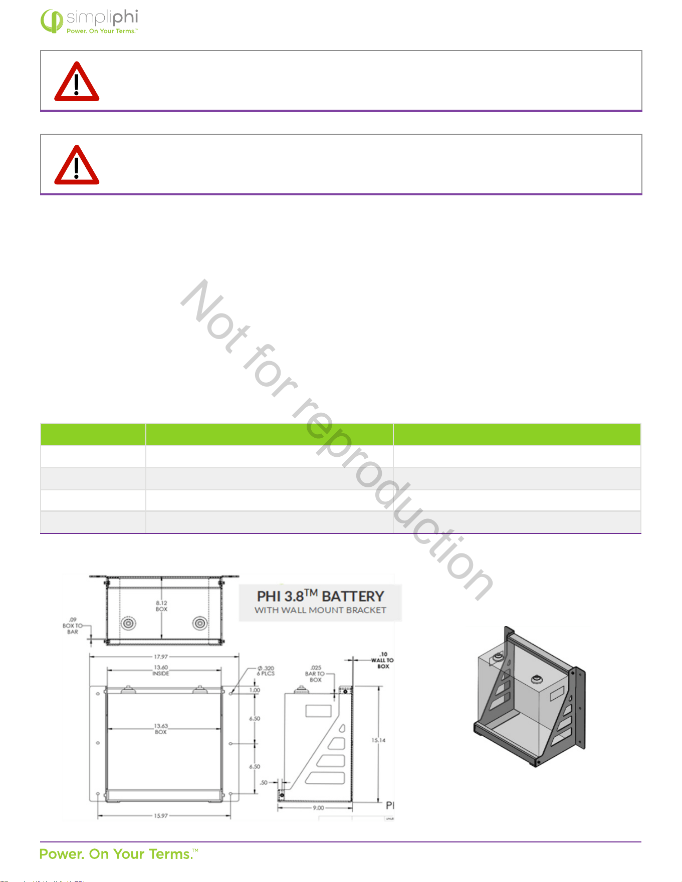
4.4 – Dimensions and Weight
Table 3.0 – Specicaons: PHI 3.8 Baery & PHI 3.8 Baery w/ Mounng Bracket
MISE EN GARDE: Ne pas associer les Baeries PHI avec d’autres marques et/ ou autres produits chimiques.
Ne pas mélanger les Baeries PHI provenant de diérentes installaons, diérents clients ou diérents sites
de travail. L’un ou l’autre de ces mélanges Annulera la Garane.
CAUTION: Do not combine PHI Baeries with other brands or chemistries. Do not mix PHI Baeries from
dierent installaons, clients or job sites. Either of these combinaons will Void the Warranty.
PHI 3.8 Baery PHI 3.8 Baery/ w/ Mounng Bracket
Width
13.5’’
13.7” (18” with mounng anges)
Height 15.5’’ (including 1.5” terminal height) 15.75” (including 1.5” terminal height)
Depth 8” 9”
Weight 86 Pounds 94 pounds
Figure 2.0 – PHI 3.8 Mounng Bracket Assembly
Not for reproduction
© SIMPLIPHI POWER, INC.
SIMPLIPHIPOWER.COM | 805-640-6700 | BSREV202111121120
15
MODEL NO. 052000
4.5.2 – Torque Value for Baeries with Threaded Studs
PHI Baeries with threaded stud terminals have a torque specicaon of 160 in-lbs. (13.3 -lbs.).
Figure 3.0 – PHI 3.8-M Threaded Stud
MISE EN GARDE: Ne pas desserrer le gros écrou en laiton à la base des bornes; cela endommagerait la
Baerie PHI et Annulerait la Garane.
CAUTION: Do not aempt to loosen the large brass nut at the base of the terminals; doing so will damage the
PHI baery and Void the Warranty.
4.5 – PHI Baery Connecon Terminals
4.5.1 – Baeries with Threaded Studs
The PHI 3.8 Baery is equipped with two 3/8’’ (10 mm) threaded studs with a lock washer and nut. The red colored high
temperature molded insert connecon is for the posive lead. The black colored high temperature insert connecon is for
the negave lead.
Water Resistant Cable Boots are also included and will be in place when your units arrive. The boots are to be placed over
the cable terminaons and will stretch to form a water-resistant seal around the base of the molded inserts and terminal
connecons.
Threaded Studs = 3/8” (10mm)
Torque Value = 160 in-lbs
Not for reproduction
© SIMPLIPHI POWER, INC.
SIMPLIPHIPOWER.COM | 805-640-6700 | BSREV202111121120
16
MODEL NO. 052000
4.6.1 – Increasing Storage Capacity via Parallel Wiring
Storage Capacity and total available Amperage is increased incrementally with the number of units wired in Parallel. For
example, two PHI 3.8 kWh-51.2Vnominal (75Ah) Baeries wired in parallel are rated at a combined 7.6 total kWh, 51.2
Volts DC and 150Ah. Each PHI 3.8 kWh-51.2Vnominal Baery also has a maximum connuous discharge rate of 37.5 Amps
DC and paralleling two of these baeries incrementally increases the maximum connuous charge and discharge rate. The
two paralleled PHI 3.8 kWh-51.2Vnominal baeries have a combined maximum connuous charge and discharge rate of 75
Amps DC (2 × 37.5ADC).
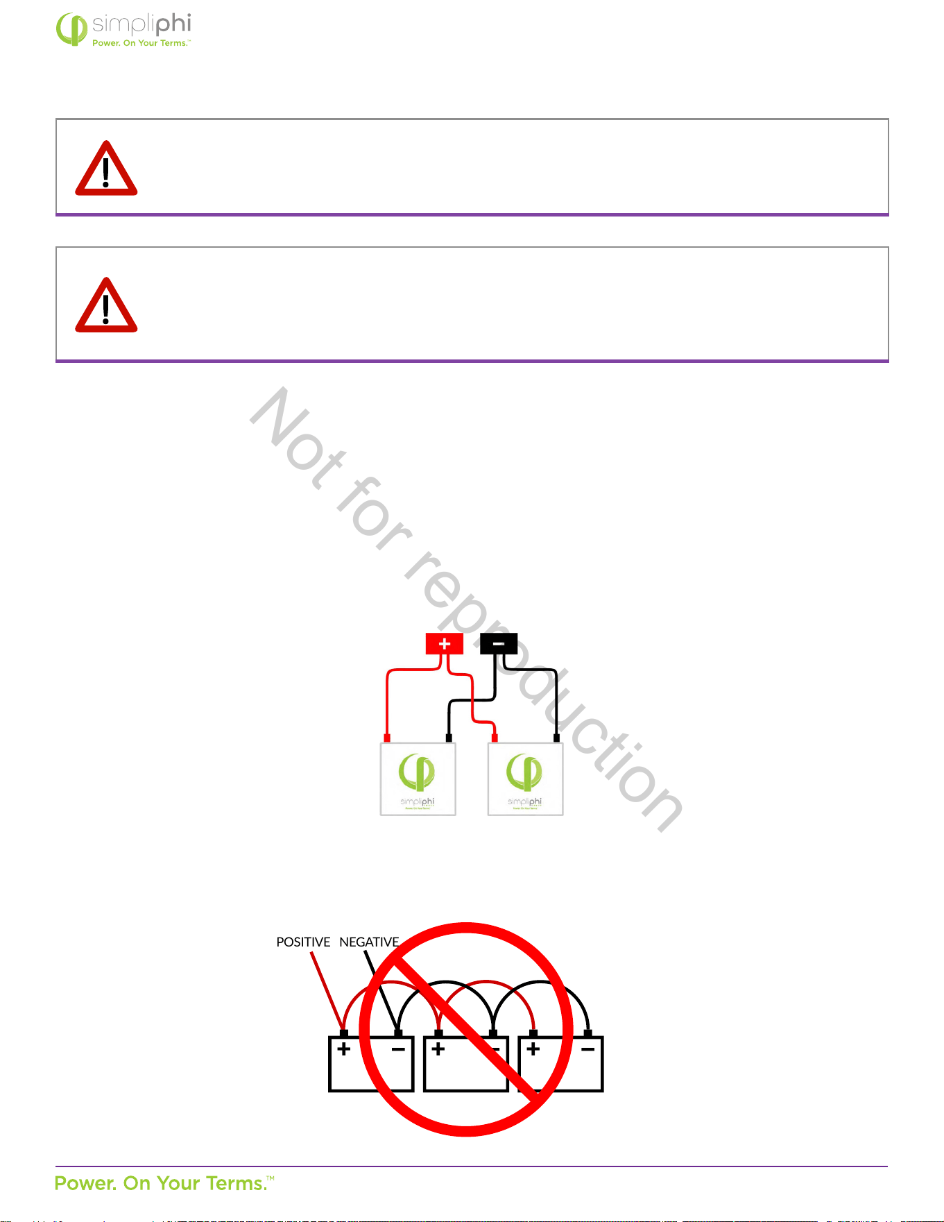
4.6.2 – Parallel Wiring Baeries with Threaded Studs using Baery Cables
PHI Baeries are paralleled by wiring from individual PHI Baeries to DC busbars or plates, which may be located in a DC
combiner box or the inverter’s power panel.
Figure 4.0 – Two PHI Baeries in Parallel
MISE EN GARDE: Toutes les Baeries PHI sont conçues pour performer à des tensions xes et ne peuvent
pas être câblées en série pour augmenter la tension de la baerie. Le câblage des Baeries PHI en série
endommagera les circuits de protecon interne de la Baerie PHI et Annulera la Garane. Les Baeries PHI
sont conçues uniquement pour un câblage en parallèle, cela pour augmenter la capacité de stockage de la
baerie.
CAUTION: All PHI Baeries are designed to serve at xed voltages and cannot be wired in series to increase
the baery bank’s voltage. Wiring the PHI Baeries in series will result in damage to the PHI Baery’s
protecve circuitry and will Void the Warranty. PHI baeries are designed for parallel wiring only to increase
the baery bank’s storage capacity.
Although lead acid baeries are typically wired using baery-to-baery interconnecng cables, SimpliPhi asks that PHI
Baeries NOT be wired in this way.
Figure 5.0 – Incorrect PHI Baery Wiring
4.6 – Wiring
POSITIVE NEGATIVE
+ + +
Not for reproduction
© SIMPLIPHI POWER, INC.
SIMPLIPHIPOWER.COM | 805-640-6700 | BSREV202111121120
17
MODEL NO. 052000
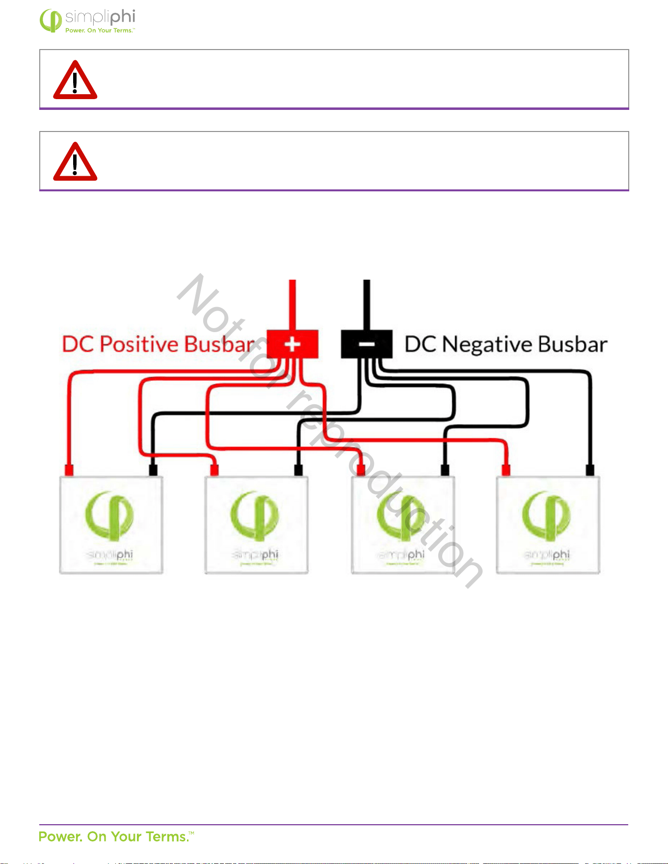
Figure 6.0 depicts four PHI Baeries wired in Parallel. This conguraon requires 8 idencal lengths of idencal gauge
copper wire.
Figure 6.0 - Four PHI Baeries in Parallel
MISE EN GARDE: Impéravement respecter toutes les instrucons de câblage en parallèle. Il est important
de noter que chaque l , relié aux Baeries PHI dans un groupe de baeries, soit d’une longueur et d’une
taille idenque. Un mauvais câblage des Baeries PHI en parallèle Annulera la Garane.
CAUTION: Idencal wire lengths and idencal wire gauges from each PHI Baery in a PHI Baery bank is
a crical feature of parallel power storage systems that must be adhered to throughout all parallel wiring
instrucons. Failure to properly wire the PHI Baeries in parallel will Void the Warranty.
Not for reproduction
© SIMPLIPHI POWER, INC.
SIMPLIPHIPOWER.COM | 805-640-6700 | BSREV202111121120
18
MODEL NO. 052000
Helpful Tips:
• SimpliPhi’s complete wiring guide can be found at this link: hps://simpliphipower.com/wp-content/uploads/
documentaon/phi-series/simpliphi-power-phi-series-baeries-threaded-terminal-wiring-guide.pdf
• Power cabling for paralleling PHI Baeries is not included. All wire should be an appropriate gauge and construcon
to handle the loads that will be placed upon it. Heavy gauge, high strand copper wire is the industry standard due to its
stability, eciency and overall quality.
• Each PHI Baery’s individual wire runs are typically sized at 4 AWG, according to the 80A built-in breaker.
• Conductor ampacity can be determined using Naonal Electrical Code tables.
• Depending on the electrical code of the local Authority Having Jurisdicon, the PHI Baery leads’ gauge may need to be
sized according to the built-in breaker or according to the PHI Baery’s surge rang.
• Baery cables can be custom ordered to include the 3/8” lugs that t on the PHI Baery’s threaded studs.
• Determine the cable length for the PHI Baery terminal farthest from the common busbar or plate rst.
• Addional cabling or slack that remains with the shorter distance runs can be coiled and secured with Zip Ties.
• Wire length should be kept as short as praccal.
• Posive wire runs should be separated from negave wire runs in separate conduit.
• Energy supplied by the PHI Baery is reduced as electrical current moves through wire. For lengths of baery cable
greater than ~10 feet (3 meters), ensure that the voltage drop is no greater than 3%.
• To take full advantage of the combined PHI Baery bank’s surge rang, the DC busbars or plates that the individual PHI
Baeries are wired to should be rated to match the PHI Baery bank’s total surge rang.
• MidNite Solar produces the MNLB Lithium Baery Combiner (rated at 250 Amps MAX) and the MNBCB 1000/50
Baery Combiner (rated at 1,000 Amps MAX)
MISE EN GARDE: Ne pas inverser la polarité. Les câbles posifs de la baerie doivent être raccordés aux
bornes Posives de la Baerie PHI et au jeu de barres ou plaques CC Posives. Les câbles de la baerie
Négave doivent être raccordés aux bornes Négaves de la Baerie PHI et au jeu de barres ou plaques CC
Négaves. Inverser la polarité Annulera la Garane.
CAUTION: Do not reverse polarity. Posive baery cables must connect to the PHI Baery’s Posive
terminal studs and to Posive DC busbars or plates. Negave baery cables must connect to the PHI
Baery’s Negave terminal studs and to Negave DC busbars or plates. Reversing polarity will Void the
Warranty.
Not for reproduction

© SIMPLIPHI POWER, INC.
SIMPLIPHIPOWER.COM | 805-640-6700 | BSREV202111121120
19
MODEL NO. 052000
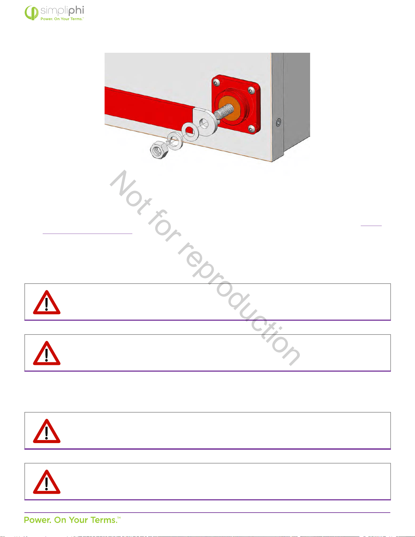
Figure 7.0 – Lug Placement on PHI Baery Threaded Stud
MISE EN GARDE: Aucune pièce (comme une rondelle) ne doit être placée entre la borne de transport de
courant et la cosse de câble ou bien le jeu de barres d’interconnexion. Cela Annulera la Garane.
MISE EN GARDE: Une éncelle peut apparaître lors de la connexion des ls aux bornes de la Baerie PHI.
Assurez-vous que le disjoncteur intégré à la baerie est en posion OFF pour minimiser le risque de choc ou
d’éncelles lors de l’installaon du système.
CAUTION: No material (such as a washer) should be placed between the current carrying terminal and the
cable lug or interconnecng busbar. Doing so will Void the Warranty.
CAUTION: Spark may be present when connecng wires to PHI baery terminals. Be sure the baery’s built-
in circuit breaker is in the OFF posion to minimaze the risk of shock or sparks during system installaon.
Not for reproduction
© SIMPLIPHI POWER, INC.
SIMPLIPHIPOWER.COM | 805-640-6700 | BSREV202111121120
20
MODEL NO. 052000
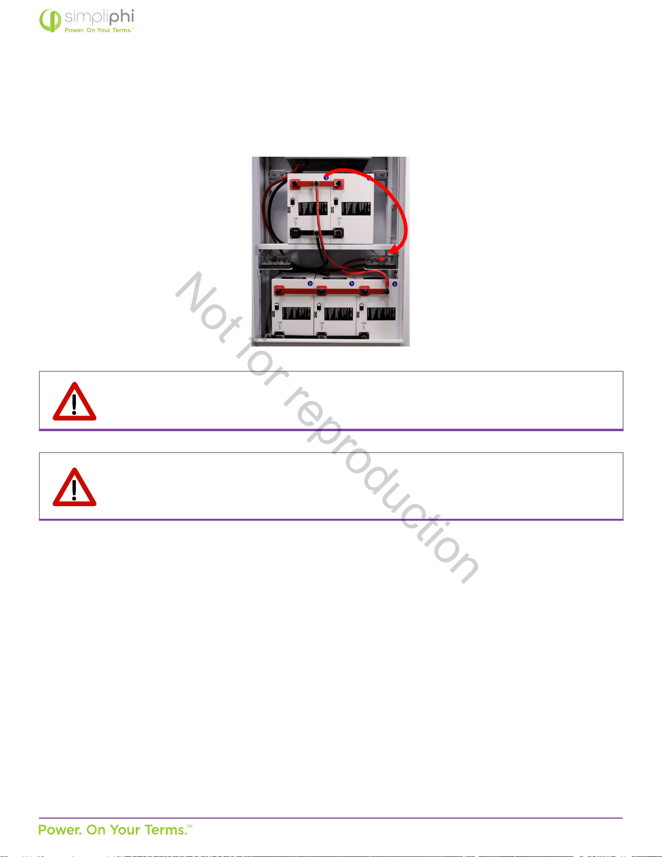
4.6.3 – Parallel Wiring Baeries with Threaded Studs using Interconnecng Busbars
PHI Baeries can be paralleled using common bussing directly aached to the baeries’ terminals. Best pracce involves
wiring the baery leads to opposite ends of the busbars, as illustrated in Figure 8 below. Interconnecng busbars for
paralleling either two (SKU #BB-2) or three (SKU #BB-3) PHI baeries with threaded studs are available from SimpliPhi at
an addional cost.
Figure 8.0 - PHI Baery Wiring Using Interconnecng Busbars
MISE EN GARDE: Encore une fois, aucune pièce (comme une rondelle) ne doit être placée entre la borne de
courant et la cosse du câble, ou bien le jeu de barres. Le jeu de barres d’interconnexion sont d’abord placées
sur les bornes des Baeries PHI, puis la rondelle suivi de la rondelle d’arrêt et enn de l’écrou, le tout xé à la
borne.
CAUTION: Again, no material (such as a washer) should be placed between the current carrying terminal and
the interconnecng busbars. The interconnecng busbars are placed on the PHI Baeries’ terminals rst,
then the at washer, lock washer, and nut are secured to the terminal posts
Not for reproduction
© SIMPLIPHI POWER, INC.
SIMPLIPHIPOWER.COM | 805-640-6700 | BSREV202111121120
21
MODEL NO. 052000
Figure 9.0 - Interconnecng Busbar Placement on PHI Baery Threaded Stud
Helpful Tips:
• The interconnecng busbars’ rangs should match or exceed the PHI Baery bank’s total surge rang.
• Busbars for paralleling more than two or three PHI Baeries can be sourced from Storm Power Components: hps://
stormpowercomponents.com/.
• SimpliPhi recommends paralleling PHI Baeries using interconnecng busbars (not baery cables) for PHI Baery Banks
consisng of more than 20 PHI Baeries for a cleaner installaon.
• Size the baery cables leading from the interconnecng busbars to the Balance of System equipment using the Naonal
Electrical Code’s Conductor Ampacity tables.
MISE EN GARDE: Ne pas inverser la polarité. Uliser un voltmètre pour vérier la polarité avant de se
connecter aux bornes de la baerie. Inverser la polarité Annulera la Garane.
MISE EN GARDE: Les Baeries PHI devraient être installées, câblées et mises en service par un installateur
agréé ou un électricien professionnel qui connaît les mesures de sécurité électriques générales et les
exigences parculières du code régional.
CAUTION: Do not reverse polarity. Use a voltmeter to check polarity before making connecons to the
baery terminals. Reversing polarity will Void the Warranty.
CAUTION: PHI Baeries should be installed, wired and commissioned by a cered installer or professional
electrician who is familiar with general electrical safety precauons and specic regional code requirements.
4.7 – Baery System Commissioning
Not for reproduction
© SIMPLIPHI POWER, INC.
SIMPLIPHIPOWER.COM | 805-640-6700 | BSREV202111121120
22
MODEL NO. 052000
If the PHI Baery’s voltage has dropped (during an extended period in storage) to a voltage below the inverter’s minimum
starng voltage requirement, then the baery will need to be charged using a plug-in / external charger. SimpliPhi’s baeries
have a very low self-discharge rate and typically do not require ancillary charging. If the PHI Baery’s voltage has dropped due to
over-discharge, try the steps outlined in Secon 6.0 – Troubleshoong prior to using ancillary charging equipment.
MISE EN GARDE: Uniquement uliser un chargeur LFP approuvé par SimpliPhi si une charge auxiliaire est
nécessaire avant l’installaon, une mise à l’essai ou un dépannage. Ne pas uliser un chargeur LFP approuvé
par Simpliphi endommagera les Baeries PHI et Annulera la Garane. Voir l’Annexe C pour plus de détails sur
les chargeurs approuvés.
MISE EN GARDE: Ne pas desserrer le gros écrou en laiton à la base des bornes ; cela endommagerait la
Baerie PHI et Annulerait la Garane.
CAUTION: Only use a SimpliPhi approved LFP charger if ancillary charging is required before installaon,
tesng or troubleshoong. Failure to use a SimpliPhi approved LFP charger will damage the PHI Baeries
and Void the Warranty. See Appendix C for more details on approved chargers.
CAUTION: Do not aempt to loosen the large brass nut at the base of the terminals; doing so will damage the
PHI baery and Void the Warranty.
CAUTION: All SimpliPhi Power Core Power and Peak Power products are designed to work exclusively in
parallel. Never connect in series to achieve higher voltages. Wiring in series will destroy the PHI baeries
and Void the Warranty.
Verify polarity at all connecons before energizing system. Reverse polarity at the PHI Baery terminals will
destroy the PHI baeries and Void the Warranty.
1. Before installing the PHI Baery, inspect the baery for any signs of damage. Do not install or operate the baery if it has
been damaged during shipping.
2. Prepare the baery module for installaon by removing its plasc terminal covers, 11/16” stainless steel hex nuts and 3/8”
lock washers from the baery terminals and set aside.
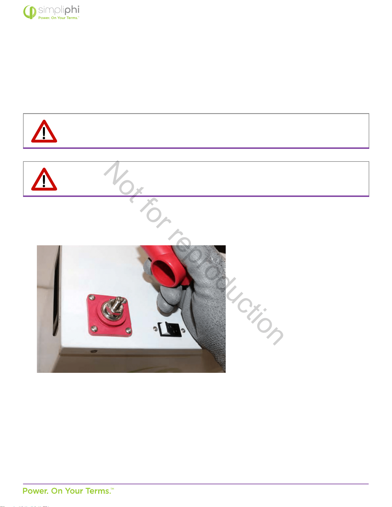
3. Before installing the PHI Baery, test its voltage by turning its built-in breaker to the ON (I) posion.
4. Measure the PHI Baery’s voltage with a mulmeter. Baeries typically ship at 20% State of Charge, which correlates with
~50.2 VDC.
5. When installing more the one PHI Baery, check that the baeries’ voltage readings are similar. Baeries with a voltage
variance greater than 1 Volt DC should be isolated and charged separately.
6. Aer tesng the PHI Baery’s voltage, turn the baery’s built-in circuit breaker back to the OFF (0) posion.
7. Wire the PHI Baery bank with all the included PHI Baeries’ built-in breakers in the OFF (0) posion.
Not for reproduction
© SIMPLIPHI POWER, INC.
SIMPLIPHIPOWER.COM | 805-640-6700 | BSREV202111121120
23
MODEL NO. 052000
MISE EN GARDE: Les Baeries SimpliPhi doivent fonconner en accord avec une programmaon appropriée
du Système Equilibré. Un fonconnement des baeries avec un équipement qui n’a pas été programmé selon
les paramètres spéciés par Simpliphi endommagera les Baeries PHI et Annulera la Garane.
MISE EN GARDE: Charger les baeries à une température inférieure à 0° C (32° F) Annulera la Garane.
CAUTION: SimpliPhi Baeries must operate in conjuncon with properly programmed Balance of System
equipment. Operang the baeries with equipment that has not been programmed to SimpliPhi’s specied
parameters will damage the PHI baeries and Void the Warranty
CAUTION: Remember that charging the baeries in sub-freezing condions will Void the Warranty.
8. Conrm all loads are turned OFF. Disconnect the inverter’s AC Output breaker or turn o the breaker at the top of your
loads’ breaker panel.
9. The main DC disconnect in the inverter’s power panel should sll be in the OFF posion.
10. Turn all baery circuit breaker switches to the ON (I) posion.
11. Turn the main DC disconnect in the inverter’s power panel ON.
12. At this point, the inverter may come on automacally in standby mode, or the inverter might need to be manually turned on.
13. Program the Balance of System Equipment (inverter and/or charge controller) to SimpliPhi’s sengs, as specied in the
relevant Integraon Guide (hps://simpliphipower.com/product-documentaon/) and generally outlined in Secon 5.0 –
Programming of this Manual.
14. Charge the baeries fully. When rst commissioning the baery system, the baeries must be charged fully before
connecng any loads. Neglecng to charge the baeries fully when rst commissioning the baery system will Void the
Warranty.
15. Baery charging may be accomplished via the inverter/charger using an AC power source such as the grid or a generator, or
via a charge controller using power from a connected solar PV array.
16. The baeries will bulk charge to 56 VDC, will Absorb for 6 minutes (0.1 hours), and will then rest at approximately 53.3
VDC. At this point in the charging cycle, these voltages (53.3V / 26.7V / 13.3v) are considered 100% SOC.
17. Once the baeries are fully charged, turn on the inverter’s AC Output breaker and/or the breaker at the top of your loads’
breaker panel.
MISE EN GARDE: Tous les produits SimpliPhi Power Core Power et Peak Power sont conçus pour fonconner
exclusivement en parallèle. Ne jamais les connecter en série pour obtenir une tension plus élevée. Le câblage
en série détruira les Baeries PHI et Annulera la Garane.
Vérier la polarité de tous les branchements avant de mere le système sous tension. Une polarité inverse
aux bornes de la Baerie PHI détruira les baeries PHI et Annulera la Garane.
Not for reproduction
© SIMPLIPHI POWER, INC.
SIMPLIPHIPOWER.COM | 805-640-6700 | BSREV202111121120
24
MODEL NO. 052000
MISE EN GARDE: Ne pas mélanger les Baeries PHI avec d’autres marques ou autres produits chimiques.
Cela Annulera la Garane.
CAUTION: Do not combine PHI Baeries with other brands or chemistries. This will Void the Warranty.
4.8 – Baery Bank Expansion
New SimpliPhi Baeries that are added to an exisng SimpliPhi baery bank must be of the same nameplate voltage and form
factor. If higher capacity PHI baeries are added, such as PHI 3.8-M to a bank of PHI 3.5, the baery bank’s total energy capacity
for system sizing calculaons is the sum of the original baery capacity rang (3.5) mulplied by the new total number of PHI
baeries. Therefore, the capacity rang of the original 3.5 PHI baeries determines the capacity rang for the newer PHI 3.8-M
baery once installed with the original baery bank. For example, a baery bank composed of two PHI 3.5 baeries and one
PHI 3.8-M baery has a total energy storage capacity for system sizing calculaons of 10.5 kWh for the bank (3 X 3.5 kWh= 10.5
kWh total). In addion, the Warranty for the new, addional PHI 3.8-M baery adopts the Warranty and Warranty period for
the original bank of PHI 3.5 baeries.
Consult SimpliPhi Power Technical Support if you wish to expand a SimpliPhi baery bank.
In addion to adhering to all other Installaon Manual instrucons, refer to the following guidelines when expanding upon an
exisng SimpliPhi baery bank:
1. Charge the exisng baery bank (“Bank A”) according to normal charging procedure (48V PHI baeries charge to 56V and
“rest” at approximately 52.5 - 53.5V aer being taken o a charge).
2. Disconnect Bank A from the system, by either
A. Disconnecng all baery cables leading from Bank A’s baeries to the baery combiner box, panelboard, or inverter’s
power panel, OR
B. Turning o the 80A breakers included in each of Bank A’s baeries
3. Connect the addional baeries (Bank B) to the system, following all wiring instrucons and torque specicaons outlined
in previous secons of segment 4.0 in this manual.
4. Modify the sengs in the system’s inverter/charger(s) or charge controller(s), whichever device will be used to inially
charge Bank B.
A. Adjust the charge rate in accordance with the number of baeries in Bank B
5. Charge Bank B fully, making sure all loads are disconnected at the me of inial charge
6. Wire all Bank A baeries and Bank B baeries in parallel, adhering to the wiring methods outlined in Secon 4.3 above.
A. Ensure that DC Posive common bus and DC Negave common bus rangs are appropriate for the new larger quanty
of baeries in the bank.
7. Reprogram all inverter/charger and/or charge controller equipment for the new larger baery bank capacity.
A. New charging current parameters for the expanded bank should be appropriate for the oldest included PHI baery
model. For example, a baery bank composed of one PHI 3.5 baery with a maximum connuous charge rate of
34 Amps DC and one PHI 3.8-M baery with a maximum connuous charge rate of 37.5 Amps DC has a combined
maximum connuous charge rate of 68 Amps DC (not 71.5 Amps DC).
Not for reproduction
© SIMPLIPHI POWER, INC.
SIMPLIPHIPOWER.COM | 805-640-6700 | BSREV202111121120
25
MODEL NO. 052000
Recommended Operang Condions for 10 Year Warranty
Equivalent to 80% Retained Capacity 10,000 cycles 5,000 cycles 3,500 cycles
Depth of Discharge (DoD) 80% 90% 100%
Operang Temperature °F (°C) 32 to 120 (0 to 49)
Programming Sengs for Ancillary
Equipment
48V
Low Baery Cut-O Voltage (V) 50.2 49.6 48
Absorb / Charging Voltage 56V
Absorb Time 6 minutes (0.1 Hours)
Absorb End Amps (if applicable) 2% of the PHI Baery bank’s total Ah capacity
Notes / Operang Limitaons for PHI Baeries
PHI 3.8-M
Minimum Operang Voltage 48V
Connuous Discharge Rate (ADC) 37.5
Surge Discharge Rate (ADC) –
10 minutes maximum
80
Connuous Charge Rate (ADC) 37.5
5.0 – Programming
5.1 – Operang Parameters Related to Cycle Life
To maintain opmal PHI Baery health and longevity, adhere to the operang parameters outlined in Tables 5.0 and 6.0 below.
Refer to the manufacturer-specic Integraon Guide from SimpliPhi’s Product Documentaon web page for a complete list of
sengs: hps://simpliphipower.com/product-documentaon/.
Table 5.0 – Opmal Operaon Parameters
Table 6.0 – Operang Limitaons
• Levels are typically @ 25°C and may need adjusng at temperature extremes.
• When performing rapid deep charge/discharge cycles, the PHI Baery should be allowed to “rest” 15 mins in between.
Although the PHI baery charges to the voltages outlined above, the baery “rests” at approximately 53.3V. Refer to Table 6.0
below for a complete Baery Voltage versus State of Charge (SOC) gauge.
Not for reproduction
© SIMPLIPHI POWER, INC.
SIMPLIPHIPOWER.COM | 805-640-6700 | BSREV202111121120
26
MODEL NO. 052000
SOC Voltage Under Discharge Load < C/2
100% > 52.5 VDC
95% 51.7 VDC
90% 51.65 VDC
75% 51.4 VDC
50% 51.0 VDC
20% 50.2 VDC
10% 49.5 VDC
0% 48.0 VDC
Table 7.0 – Voltage/SOC correlaon under load
MISE EN GARDE: Avant la mise en service du système, le contrôleur et l’onduleur doivent être programmés
conformément aux recommandaons du fabricant avec les réglages appropriés. Consultez les manuels
du fabricant et/ou les Guides d’Intégraon indiqués sur la page internet de la Documentaon Produit de
SimpliPhi (Schneider, Magnum, Outback, etc.). Ne pas respecter ces instrucons endommagera les Baeries
PHI Annulera la Garane.
les tableaux d’Intégraon du Contrôleur de Charge sont uniquement fournis à tre d’exemple.
CAUTION: Before commissioning the system, the appropriate controller and inverter sengs must be
programmed per the manufacturer’s recommendaons. Consult the manufacturer’s manuals and/or the
Integraon Guides listed on SimpliPhi’s Product Documentaon web page (Schneider, Magnum, Outback,
etc.). Failing to do so will damage the PHI baeries and will Void the Warranty. The following Charge
Controller Integraon tables are for general reference only.
6.0 – Troubleshoong
If your PHI Baery bank is reaching its Low Baery Cut Out voltage (LBCO), load disconnects or load shedding set points may
need to be adjusted.
The PHI baeries are reading extremely low or no voltage:
Programmed sengs in the PHI Baery’s accompanying Balance of System equipment should prevent the PHI Baery’s internal
BMS from reaching its low voltage seng. However, in the instance that the PHI Baery’s BMS has turned the PHI baery o,
the baery will read low or no voltage, and the following steps should be taken to re-set the BMS:
1. Turn o each of the built-in breakers in all of the PHI Baeries in the baery bank*.
2. Turn o the main DC disconnect located in the inverter’s power panel, between the baery bank and the inverter.
3. Turn o the main breaker at the top of the inverter’s AC distribuon panel or sub-panel.
4. Wait 5 minutes, for the BMS in each baery to re-set itself.
5. Use a mul meter to take voltage measurements of each PHI baery in the baery bank, to make sure the voltage increased
to the minimum voltage necessary for the inverter to turn on.
To measure a single baery’s voltage within a baery bank, only the baery being measured has its built-in breaker in the
ON (I) posion; all other baeries in the bank must have their built-in breakers OFF (0).
6. Turn on each of the built-in breakers in all of the PHI Baeries in the baery bank.
7. Turn on the main DC disconnect located in the inverter’s power panel.
Not for reproduction

© SIMPLIPHI POWER, INC.
SIMPLIPHIPOWER.COM | 805-640-6700 | BSREV202111121120
27
MODEL NO. 052000
8. Check that all parameters in the Balance of System equipment are programmed according to the relevant SimpliPhi
Integraon Guide. Failure to do so will damage the PHI baeries and Void the Warranty.
9. To charge the baeries quickly, SimpliPhi recommends using an AC power source to immediately charge the PHI baery
bank via the inverter’s charger. However, the PHI baeries will not incur any damage if they are charged using a connected
solar PV array via the charge controller. The important aspect of this step is that the baeries re-charge as soon as the BMS
has re-set.
10. Turn on the inverter’s AC Input breaker and turn on the inverter.
11. The inverter should automacally self-iniate a baery charge. However, a Force Charge may need to be iniated in the
inverter.
Not for reproduction

© SIMPLIPHI POWER, INC.
SIMPLIPHIPOWER.COM | 805-640-6700 | BSREV202111121120
28
MODEL NO. 052000
Appendix A – PHI Baery Safety & Green Aributes,
Cercaons
This Appendix secon covers the PHI Baery safety aributes and cercaons, such as the lack of thermal runaway with
re propagaon, o-gassing, UN DOT cercaon and UL compliance and cercaon. It also covers the PHI Baery’s green
aributes – from products to materials to disposal, as well as relevant environmental and ecological consideraons.
A.1 – Safety Aributes and Cercaons
A.1.1 – Intrinsically Safe Operaon and Installaon
The PHI Lithium Ferrous Phosphate (LFP) baery cell component is made with an intrinsically safe cathode material (iron
phosphate). This creates a strong molecular bond, which withstands extreme condions, prolongs cycle life, and maintains
integrity with lile or no maintenance over extended periods of me. There is virtually no danger of Thermal Runaway with
re propagaon, as there may be with Lead Acid, NiCd, and Lithium Cobalt type baeries (NCA, NMC, LCO). No venng or
cooling is required. No precauons or special structural consideraons are necessary when installing PHI Baeries.
A.1.2 – No Safety Hazards due to O-Gassing, Exposure to Acids, Thermal Runaway
PHI Baeries do not vent dangerous gasses during normal operaon, such as hydrogen and oxygen, because chemicals
contained in Lithium Ferro Phosphate cells’ electrolyte do not electrolyze to any appreciable extent within the PHI Baery’s
operang voltage range. In contrast, lead acid baeries which contain water and sulfuric acid experience signicant
electrolysis into H2 and O2 during normal operaon. There are no dangers of exposure to sulfuric acid because PHI
Baeries do not have causc electrolytes. Thermal runaway with re propagaon is not an issue with PHI products due to
the basic nature of Lithium Ferro Phosphate cell chemistry ulized in all our power storage products.
A.1.3 – PHI Baery Control and Protecve Circuitry
SimpliPhi Power Inc. ulizes balancing, voltage regulaon, thermal and current controls, as well as other protecve
measures, in its PHI Baery Management System (BMS). This protecve circuitry is embedded in the architecture of each
PHI Baery.
A.1.4 – UN DOT Cered Cells
The Lithium Ferrous Phosphate (LFP) cells are independently cered to withstand the UN DOT 38.3 tesng guidelines
with no special circuitry added. These tests include short circuit, over-voltage, overcharging, extreme temperature, high
altudes, shock and extreme vibraon tesng.
A.1.5 – UL Compliance
The Lithium Ferrous Phosphate cells within the PHI Baeries fully comply with the safety tesng parameters of UL 1642.
A.1.6 – RoHS Compliant
SimpliPhi Power 3.8 Baeries are RoHS compliant. Any RoHS compliant component is tested for the presence of Lead
(Pb), Cadmium (Cd), Mercury (Hg), Hexavalent chromium (Hex-Cr), Polybrominated biphenyls (PBB), and Polybrominated
diphenyl ethers (PBDE). For Cadmium and Hexavalent chromium, there must be less than 0.01% of the substance by weight
at raw homogeneous materials levels. For Lead, PBB, and PBDE, there must be no more than 0.1% of the material, when
calculated by weight at raw homogeneous materials. Any RoHS compliant component must have 100 ppm or less of mercury
and the mercury must not have been intenonally added to the component. In the EU, some military and medical equipment
are exempt from RoHS compliance.
A.2 – Green Aributes, Environmental & Ecological Consideraons
A.2.1 – Materials
The primary materials (lithium, iron, phosphate) that make up PHI Baeries are environmentally benign and pose very few
pollung or environmentally degrading by-products in the harvesng and renement processes. This is especially true when
compared to those of lead acid, NMC, NCA, LCO, NiCad, and NiMH baeries.
Not for reproduction

© SIMPLIPHI POWER, INC.
SIMPLIPHIPOWER.COM | 805-640-6700 | BSREV202111121120
29
MODEL NO. 052000
A.2.3 – Operaon
There is no need for maintenance, such as adding water or chemicals, nor is there corrosion of terminals or containment
facilies, or dispersion of fumes as with other baery types. Once installed, PHI Baeries are maintenance free as long as all
the Installaon Manual, Integraon Guidelines and Warranty requirements are adhered to.
A.2.4 – Life Cycles
PHI Baeries are designed for thousands of cycles while maintaining 80 percent or more of their inial capacity. To achieve
this, it is crical to follow the operang condions outlined in the Warranty.
A.2.5 – Disposal
PHI products are non-hazardous, may be disposed of without damage to the ecosystem, and returned to the earth, while
easily recombining with the elements without harmful by-products. The outer casing and brackets contain steel, aluminum,
copper, cardboard, and recyclable plasc. Lithium Ferrous Phosphate (LFP) materials can also be recycled through
established baery centers if desired.
A.2.6 – Lithium Ferrous Phosphate Baeries and the Environment
As the use of this baery chemistry in larger baeries becomes more common, quesons of sustainability and
environmental impact inevitably arise. Of the lithium ferrous phosphate chemistries being considered for large format
baeries, SimpliPhi Power believes that baeries based on our proprietary lithium ferrous phosphate chemistry and
circuitry oer a clear advantage, not only over alternate Li-ion chemistries (lithium cobalt oxide), but all baery chemistries
that are currently commercially available. This belief is based on the minimal environmental impact associated with the
manufacturing of PHI Baeries, the extended cycle life and the signicantly smaller end-of-life footprint that results from
the use of PHI Baeries.
A.3 – Summary
The Lithium Ferrous Phosphate (LFP) cells ulized throughout the enre PHI and LibertyPak product lines are classied as
non-hazardous by OSHA and WHMIS. They are non-toxic, unlike NMC, NCA, LCO, NiMH, NiCad or Lead Acid types of baeries
(including AGM). The PHI Baeries contain the least amount of toxic metals and are the most eco-friendly of all common
baery types. Lithium easily combines into harmless compounds when disposed of. The PHI Baeries are the least pollung
rechargeable baeries on the market today – no fumes, leaking, or gas discharge and no chemicals or acids to worry about.
Designed and Manufactured in the USA Using Exclusive American Patented Technologies.
Not for reproduction

© SIMPLIPHI POWER, INC.
SIMPLIPHIPOWER.COM | 805-640-6700 | BSREV202111121120
30
MODEL NO. 052000
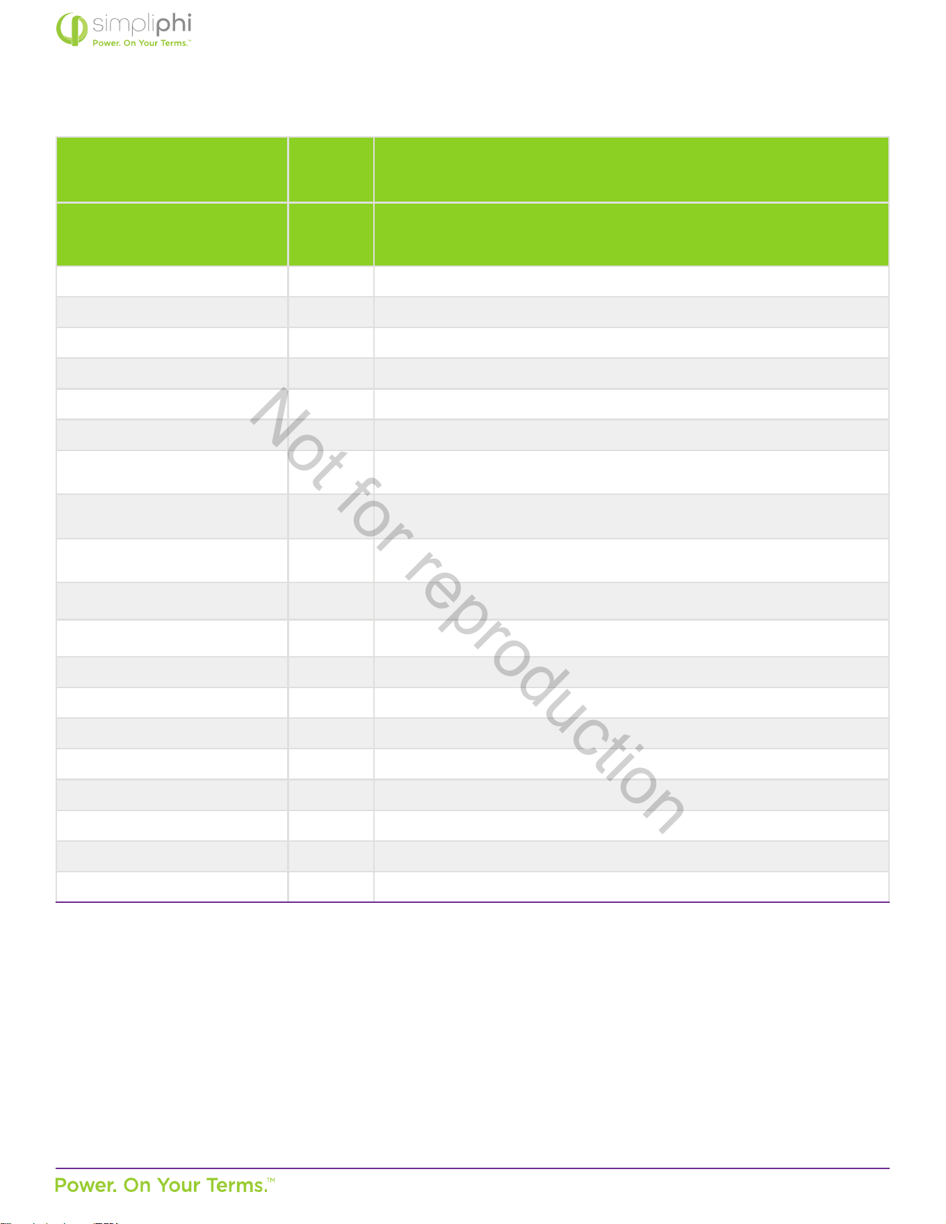
Appendix B – PHI Baery Bank Sizing Guide
48V Sizing for Maximum Instantaneous Discharge (Load Rate)
PHI 3.8 - M 51.2V
nom
Max Connuous
Dis/charge Rate
(ADC)
37.5
Max Connuous
Dis/charge Rate
(kW DC)
1.92
Inverter Make / Model
Inverter Power Rang
(kW AC)
Inverter Eciency Load Rate (kW DC)
PHI 3.8-M 51.2Vnom
Minimum Baery
Quanty
Magnum MS 4448 4.4 94% 4.7 3
Magnum MS 4048 4 94% 4.3 3
OutBack Radian 8048A 8 93% 8.6 5
OutBack Radian 4048A 4 93% 4.3 3
OutBack SkyBox 5 97% 5.2 3
OutBack VFXR 3648A 3.6 93% 3.9 3
OutBack FXR 3048A 3 93% 3.2 2
OutBack GVFX 3648
(disconnued)
3.6 93% 3.9 3
OutBack GTFX 3048
(disconnued)
3 93% 3.2 2
Schneider XW Pro 6.8 93% 7.3 4
Schneider XW+ 6848 6.8 92.5% 7.4 4
Schneider XW+ 5548 5.5 93% 5.9 4
Schneider SW 4048 4 94% 4.3 3
Selectronic SP PRO SPMC
481-AU
5 96% 5.2 3
Selectronic SP PRO SPMC
482-AU
7.5 96% 7.8 5
Sol-Ark-8K 8 96.5% 8.3 5
Sol-Ark-12K 9 96% 9.3 5
Victron Quaro
48/3000/35
3 94% 3.2 2
Victron Quaro
48/5000/70
5 95% 5.3 3
Victron Quaro
48/10000/140
10 96% 10.4 6
Victron Quaro
48/15000/200 (230 VAC)
15 96% 15.6 9
Not for reproduction
© SIMPLIPHI POWER, INC.
SIMPLIPHIPOWER.COM | 805-640-6700 | BSREV202111121120
31
MODEL NO. 052000
Sizing for Maximum Instantaneous Charge Rate
Assume charge controllers’ current output is fully ulized.
Minimum Baery Quanty
Charge Controller Make / Model
Max
Output
(ADC)
PHI 3.8 - 51.2V
Magnum PT-100 100 3
MidNite Solar Classic 150 - 48V system 86 3
MidNite Solar Classic 200 - 48V system
78 3
MidNite Solar Classic 250 - 48V system
55 2
MidNite Solar KID
30 1
MorningStar TriStar MPPT 600V 60 2
MorningStar TriStar
TS-MPPT-60/60M
60 2
MorningStar TriStar
TS-MPPT-45
45 2
MorningStar TriStar
TS-MPPT-30
30 1
MorningStar TriStar ProStar PS-MPPT-
25/25M
25 1
MorningStar TriStar ProStar PS-MPPT-
40/40M
40 2
OutBack FM 100 100 3
Schneider MPPT 60 150 60 2
Schneider MPPT 80 600 80 3
Sol-Ark-12K (includes dual MPPTs) 185 5
Victron SmartSolar MPPT 250/60 60 2
Victron SmartSolar MPPT 250/70 70 2
Victron SmartSolar MPPT 250/85 85 3
Victron SmartSolar MPPT 250/100 100 3
Not for reproduction

© SIMPLIPHI POWER, INC.
SIMPLIPHIPOWER.COM | 805-640-6700 | BSREV202111121120
32
MODEL NO. 052000
Appendix C – PHI Approved External Chargers
This Appendix secon covers the PHI Baery’s approved external / plug-in chargers.
Typically, ancillary charging of SimpliPhi’s baeries is not required, and charging using any of the charge controllers and/
or inverter/chargers listed in the “Integraon Guides” secon of the SimpliPhi web site’s Product Documentaon page is
acceptable. However, ancillary charging may be necessary in the following situaons:
1. No charge controller or inverter/charger is available
2. Increasing the baery’s State of Charge (SoC) aer an extended storage period and prior to installaon
3. For recharge purposes when the baery’s voltage is below the minimum required voltage for charge controller and/or
inverter/charger equipment to turn on
C.1 – Recommended 48V Charger
The 54.6V 4A 13 Series 48V LiFePO4 Smart Charger from WAOUKS is recommended and available online for purchase at this
link.
The 58.4V 5A 16 Series 48V LiFePO4 Smart Charger from WAOUKS is recommended and available online for purchase at this
link.
The 48V/30A for LiFePO4 / LiFeYPO4 (58.8V) + GMS charger from GWL/Power is recommended and available for online
purchase at this link.
The Smart Charger (15A) for 51.2V (16 cells) LiFePO4 Baery Pack – CH-PFC51215A charger from AA Portable Power Corp is
available online for purchase at this link.
C.4 – Alternave Chargers
If the above listed chargers are unavailable or undeliverable to your specic locaon, SimpliPhi also approves of Iota
Engineering’s baery chargers (link here) to increase the PHI baery’s voltage. These chargers should only be used in order to
increase baery voltage enough to regain system operability; these chargers should not be used to regularly and fully charge the
PHI baery.
Not for reproduction