| 1 |
REV20230706
© 2023 Briggs & Stratton. All rights reserved.
Installation Manual
AmpliPHI 3.8 Batteries
3.87
kWh

| 2 |
REV20230706
© 2023 Briggs & Stratton. All rights reserved.
Table of Contents
1.0
– Introduction ......................................................................................................................................................................... 5
1.1
– Online Resources ................................................................................................................................................................ 5
1.2
– Technical Support ........................................................................................................................................................... 5
1.3
– Product Overview .......................................................................................................................................................... 5
1.3.1
– Battery Management System (BMS) ................................................................................................................... 5
1.3.2
– Built-In Breaker ....................................................................................................................................................... 6
1.3.3
– Networking Communications Cables & Plugs .................................................................................................. 7
1.4
– Specifications .................................................................................................................................................................. 7
2.0
–Safety ..................................................................................................................................................................................... 8
2.1
– General Safety Instructions .......................................................................................................................................... 8
2.2
– Response to Emergency Situations .............................................................................................................................. 8
3.0
– Pre-Installation .................................................................................................................................................................... 9
3.1
– AmpliPHI Battery Performance .................................................................................................................................. 9
3.2
– AmpliPHI Battery System Sizing .................................................................................................................................. 9
3.2.1
– Sizing for All Systems ............................................................................................................................................. 9
3.2.2
– Additional Sizing Considerations for AC Coupled Systems .......................................................................... 9
4.0
– Installation ......................................................................................................................................................................... 10
4.1
– Installation Options ...................................................................................................................................................... 10
4.2
– Environmental Considerations ................................................................................................................................. 10
4.2.1
– Charging at Temperatures Below Freezing .................................................................................................... 10
4.2.2
– Explosive Gas Precautions ................................................................................................................................. 11
4.2.3
– Anti-Corrosion Protection ................................................................................................................................ 11
4.3
– Mounting Hardware ................................................................................................................................................... 11
4.4
– Dimensions and Weight ............................................................................................................................................. 12
4.5
– AmpliPHI Battery Connection Terminals ............................................................................................................... 12
4.5.1
– Batteries with Threaded Studs ......................................................................................................................... 12
4.5.2
– Torque Batteries with Threaded Studs ........................................................................................................... 13
4.6
– Electrical Wiring .......................................................................................................................................................... 13
4.6.1
– Increasing Storage Capacity via Parallel Wiring .............................................................................................. 13
4.6.2
– Parallel Wiring Batteries with Threaded Studs using Battery Cables ........................................................ 14
4.6.3
– Parallel Wiring Batteries with Threaded Studs using Interconnecting Busbars ....................................... 17
4.7
– Communications Wiring ............................................................................................................................................ 19
4.8
– Battery System Commissioning ................................................................................................................................ 21
4.9
– Battery Bank Expansion ............................................................................................................................................. 23
5.0
– Programming .................................................................................................................................................................... 24
5.1
– Operating Parameters per warranty ........................................................................................................................ 24
6.0
– Troubleshooting ............................................................................................................................................................... 25
Appendix A – AmpliPHI Battery Safety & Green Attributes, Certifications ................................................................... 26
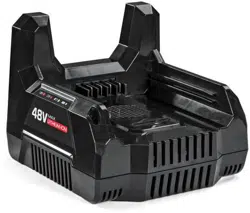
Appendix B – AmpliPHI Approved External Chargers ........................................................................................................ 28
| 3 |
REV20230706
© 2023 Briggs & Stratton. All rights reserved.
The following abbreviated guidelines do NOT encompass all AmpliPHI battery warranty details. Failure to
adhere to the warranty and Installation Manual requirements will void the warranty. Read the battery’s
complete warranty prior to installation and register the battery according to the form found at the bottom of
the
same web page address: https://simpliphipower.com/wp-content/uploads/documentation/ampliphi-
series/simpliphi-power-ampliphi-3-8-warranty.pdf
CAUTION: The following will result in damage to your PHI batteries and will void the warranty
:
1. Incorrect battery wiring and/or installation
a. Verify polarity at all connections with a standard voltmeter (1) before energizing the system and
(2) on batteries with threaded stud connections, before switching the built-in circuit breaker to
the “ON” position. Reverse polarity at the AmpliPHI Battery terminals will void the warranty and
may permanently damage the AmpliPHI Batteries.
b. AmpliPHI Batteries must be fully charged before commissioning (i.e. before connecting loads).
Failure to do so will damage the AmpliPHI batteries and void the warranty.
c. Lugs, washers and lug nuts must be installed according to the Installation Manual. Failure to do so
will damage the PHI Batteries and void the warranty. Using an impact driver or power tools on the
terminals will void the warranty. Using power tools or impact drivers may damage the terminal
even if it doesn’t result in breakage. Only use accurately calibrated and properly adjusted torque
wrenches when tightening terminal hardware.
2. Pairing the battery with incompatible equipment. Use of accessories not recommended or sold by the
manufacturer may result in a risk of fire, electric shock, or injury to persons and will void the warranty.
a. Contact Technical Support at (805) 640-6700 x 1 regarding the compatibility of any equipment
not explicitly listed in the ‘AmpliPHI Integration Guides’ section of the Product Documentation
web page (https://simpliphipower.com/product-documentation/
).
3. Incorrect inverter and/or charge controller settings. Operating the AmpliPHI Battery in conjunction with
equipment not programmed to the AmpliPHI Battery’s settings will void the warranty.
a. Refer to the ‘AmpliPHI Integration Guides’ section of the Product Documentation web page
(https://simpliphipower.com/product-documentation/)
for all inverter and charge controller
settings.
b. Although each AmpliPHI Battery contains an internal Battery Management System (BMS) with
circuitry that protects the AmpliPHI Battery cells from over-charge, over-discharge and extreme
load amperage, the AmpliPHI Battery must always be installed with appropriate inverter and/or
charge controller settings and power electronics to protect the AmpliPHI Battery from open solar
photovoltaic (PV) voltage and other high voltage charging sources.
c. Failure to protect the AmpliPHI batteries from voltages higher than the battery voltage rating (48-
56 VDC) will destroy the AmpliPHI batteries, cause electrical fires and void the warranty.
CAUTION!
THIS MANUAL IS SPECIFIC TO THE AMPLIPHI BATTERIES THAT
FEATURE INTERNAL COMMUNICATIONS WITHIN THE BMS. DO NOT
FOLLOW THESE GUIDELINES IF YOU ARE USING THE STANDARD PHI
PRODUCT LINE. PLEASE CONSULT THE INSTALLATION MANUAL
SPECIFIC FOR YOUR BATTERIES FOUND HERE: PHI BATTERY
INSTALLATION MANUAL LINK
CAUTION!
THESE 3 THINGS WILL VOID THE AMPLIPHI WARRANTY &
DAMAGE THE BATTERIES. READ IN FULL PRIOR TO BATTERY
INSTALLATION

| 4 |
REV20230706
© 2023 Briggs & Stratton. All rights reserved.
The AmpliPHI Battery warranty does NOT cover product damage caused by mishandling or improper use per the
Installation Manual, Integration Guides and warranty, exposure to liquids, impacts from falling objects or from being
dropped, or attempts to repair the battery by any party other than Briggs & Stratton. The complete list of warranty
Exclusions is included in the AmpliPHI Battery warranty document:[Amplify warranty Document]
– Introduction
1.0
– Online Resources
The Product Documentation section of Briggs & Stratton’s web site (https://simpliphipower.com/product-
documentation/) includes Specification Sheets, Warranties, Installation & Operator’s Manuals, and Integration Guides
for all Briggs & Stratton’s current and legacy products.
Briggs & Stratton’s YouTube channel (https://www.youtube.com/channel/UCcuCaLT_G3Hhumteh-pI5yg/videos) has
instructional videos showing various steps of the battery installation process in detail.
1.1
– Technical Support
Briggs & Stratton Technical Support (805-640-6700 x 1, oxnard-techsupport@basco.com) is available to take any
questions regarding this manual or general installation questions. For assistance with battery system commissioning,
Briggs & Stratton asks that a commissioning call be scheduled ahead of time with Technical Support.
We encourage you or your installer to contact Briggs & Stratton with any questions. We are committed to working with
you and your installation team to achieve a safe, reliable storage system that will provide years of maintenance- free service
that is covered by our warranty terms & conditions.
1.2
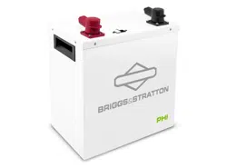
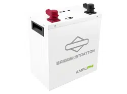
– Product Overview
The AmpliPHI deep-cycle Lithium Ferro Phosphate (LFP) Battery is optimized with proprietary cell architecture,
power electronics, Battery Management System (BMS) with communications, manufacturing materials and processes.
This assures the highest grade and quality, longest cycle-life, greatest efficiency and freedom from material impurities,
toxicity and hazardous risk. The AmpliPHI Battery is modular, lightweight and scalable. It provides power security and
seamless integration of renewable and traditional sources of energy in conjunction with or independent of the grid.
1.2.1
– Battery Management System (BMS)
Each AmpliPHI Battery contains circuitry that protects the LFP cells from damaging conditions (overcharge,
over-discharge, extreme load amperage, etc.). If pre-programmed BMS values are exceeded, the protective
circuitry will shut down the flow of electricity to/from the AmpliPHI Battery. In some cases, the BMS will
automatically resume the flow of electricity to/from the AmpliPHI Battery when the battery is no longer in
damaging conditions. In other cases, the AmpliPHI Battery’s self- protection mechanism will result in the
battery’s breaker tripping and requiring a manual re-set (refer to Section 6.0 - Troubleshooting of this Manual
for manual re-set instructions).
Regardless, once AmpliPHI Battery operation resumes and the connected inverter is back on, Briggs &
Stratton recommends checking that the inverter’s settings are still correct. Often, inverter system settings will
be saved within the inverter memory storage and will not need to be reset. Refer to Briggs & Stratton’s
AmpliPHI Integration Guides for inverter and/or charge controller settings
(https://simpliphipower.com/product-documentation/
).
| 5 |
REV20230706
© 2023 Briggs & Stratton. All rights reserved.
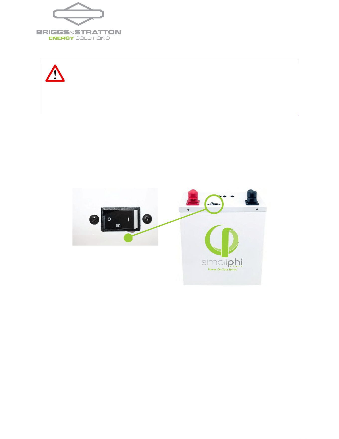
1.2.2
– Built-In Breaker
AmpliPHI batteries are outfitted with a hydraulic/magnetic circuit breaker. This breaker increases safety
during shipping and installations and allows the battery to effectively be turned “OFF” or “ON.” The breaker
works in conjunction with the battery’s built-in BMS and creates additional safety, efficiency and
functionality in the overall power storage system.
Figure 1.0 – AmpliPHI 3.8 Circuit Breaker
NOTE: Circuit breakers, disconnects and fuses should be employed throughout several points of a power storage and
generation installation to effectively isolate and protect all components of the system to safeguard against faults, short
circuits, polarity reversals or a failure of any component in the overall system. Fuses, breakers, wiring ratings and values
should be determined by established electrical codes and standards and evaluated by certified electricians, installers,
and regional code authorities.
1.2.3
– Networking Communications Cables & Plugs
Each AmpliPHI battery comes with a 4’ CAT5 cable, a terminator plug, and an RJ45 dust cover for networking
communication set-up (explained in greater detail in Section 4.7 – Communications Wiring).
CAUTION:
Although each AmpliPHI Battery contains an internal communications based BMS
with circuitry that protects the AmpliPHI Battery cells from over-charge, over- discharge and
extreme load amperage, the AmpliPHI Batteries must always be installed with appropriate
inverter and/or charge controller settings to protect the AmpliPHI Battery from open PV
voltage and other high voltage charging sources. Exposure to higher voltage than the
AmpliPHI battery rating (48-56 VDC) will void the warranty and may damage the AmpliPHI
batteries..

| 6 |
REV20230706
© 2023 Briggs & Stratton. All rights reserved.
1.3
– Specifications
Please review Table 1.0 below for AmpliPHI Battery specifications, including physical dimensions, warranty period, and
technical data.
Table 1.0 - AmpliPHI Battery Specifications
AmpliPHI 3.8™ (51.2V
nominal
)
AmpliPHI 3.8™ Internal BMS
DC Voltages - Nominal
51.2
VDC
Programmed Absorb Voltage
56
VDC
Amp-Hours
75 Ah
Programmed Float Voltage
54
VDC
Rated Capacity
3.8 kWh DC at 100% DoD
3.04kWh DC @ 80% DoD
Over-Voltage Fault Trip
2
60
VDC
MAX Discharge Rate (10
minutes)
100 Amps DC
(5.1 kW DC)
Low-Voltage Fault Trip
2
45
VDC
MAX Continuous
Discharge & Charge Rate
37.5 Amps DC
(1.9 kW DC)
Programmed Discharge &
Charge Rate per battery
2
37.5 Amps DC
(1.9 kW DC)
DC Voltage Range
1
48 to 56 VDC
Depth of Discharge
1
up to 100%
Self-Discharge Rate
<
1%
per
month
(with
battery
off)
Charging Low Temperature
Fault Trip
2
32° F (0° C)
Charging Temperature
1
32° to 120° F (0° to 49° C) Discharging Low Temperature
Fault Trip
3
-4° F (-20° C)
Operating Temperature
1
-4° to 140° F (-20° to 60° C)
High Temperature Fault Trip
3
158° F (70° C)
Storage Temperature 6 months: 14° to 77° F (-10° to
25° C)
3 months: -4° to 113° F (-20° to
45° C)
Memory Effect
None
Maximum Quantity of
Networked Batteries
40
Cycle Life
10,000+ cycles (@ 80% DoD)
Networking Cable
CAT5 or
warranty Period
10 Years
Networking Port
RJ45
Weight
86 lbs. (39 kg)
Dimensions (W x H x D)
13.5 x 14 x 8 in. (15.5” H
w/terminals) / 0.88 ft
3
(34.3 x
35.6 x 20.3 cm / 0.025 m
3
)
N
o
t
e
s
:
1
Max operating ranges. Operating outside of these conditions will void your warranty.
2
These AmpliPHI BMS Fault Trip conditions result in the need for the BMS to be re-set manually (refer to Section 6.0 -
Troubleshooting of this Manual)
3
These AmpliPHI BMS Fault Trip conditions result in automatic BMS reconnection when fault conditions are no longer
detected. There is no need to re-set the BMS manually in these instances.
Specifications are typical/nominal. Subject to change without notice.

| 7 |
REV20230706
© 2023 Briggs & Stratton. All rights reserved.
CAUTION: While water is an acceptable and effective extinguishing agent for the AmpliPHI
Battery model, the Balance of System equipment used in conjunction with the AmpliPHI
Batteries may require specialized extinguishers such as FM-200 or CO2 suppression
systems.
2.0
–Safety
For safety reasons, read all instructions and cautionary markings on the AmpliPHI Batteries, and all appropriate sections
of this manual. Failure to follow instructions provided in the Installation Manual, Integration Guides and/or warranty
will void the warranty.
2.1
– General Safety Instructions
•
Do not operate if the AmpliPHI Battery has been damaged in any way during shipping or otherwise.
•
To reduce the chance of short-circuits, always use insulated tools when installing or working with AmpliPHI
batteries or other electrical equipment.
•
Remove personal metal items such as rings, bracelets, necklaces, and watches when working with AmpliPHI
batteries and electrical equipment. Wear insulated gloves and rubber shoes.
•
AmpliPHI Batteries pose some risk of shock or sparking during the installation and initial wiring and connection
process. This is consistent with all other battery-based storage formats. To minimize the risk of shock or sparks
during the installation and commissioning of the system, make sure the built-in breaker is in the “OFF” position.
•
To avoid a risk of fire and electric shock, make sure that existing system wiring is in good condition and that the
wire is not undersized. Do not operate the AmpliPHI Battery in conjunction with damaged or substandard wiring.
These safety precautions are in addition to the Warnings previously outlined on page 4 of this Manual.
2.2
– Response to Emergency Situations
As with any battery, if the AmpliPHI Battery’s cells are severely damaged due to physical abuse, reverse polarity, high
voltage, unmitigated current or other electrical phenomenon incurred outside of Warranted specifications, it can
cause electrolyte leakage and other failures. The electrolyte can be ignited by an open external flame. However, unlike
other lithium ion batteries with cobalt oxides (e.g. LCO, NCM and NCA), the AmpliPHI LFP Batteries’ electrolyte and
other material components generate a limited amount of heat and do not go into a state of thermal runaway with fire
propagation. The Briggs & Stratton UL 1973 Battery Certification verifies “No Thermal Runaway” (see MSDS for
chemical analyses).
While PHI Batteries do not go into thermal runaway with fire propagation, the following protocol should be followed
in the event that the PHI batteries are subjected to electrical fire caused by other system components or failures:
•
Ensure that the system is no longer energized, either from the solar array or the grid (main disconnect).
•
Separate any external cables from batteries if present (cut if necessary) using insulated tools.
•
Wear a respirator or dust mask to avoid inhaling soot/dust.
•
Wear insulating and abrasion-resistant gloves (if permeable, over nitrile or similar gloves).
•
Move battery debris into non-conductive bins capable of handling the weight.
•
Dispose as regulations require.

| 8 |
REV202307060
© 2023 Briggs & Stratton. All rights reserved.
CAUTION: An AmpliPHI Battery bank cannot exceed 40 modules per bank. Sizing AmpliPHI
battery banks larger than 40 battery modules potentially causes damage to the AmpliPHI
batteries and voids the warranty.
3.0
– Pre-Installation
3.1
– AmpliPHI Battery Performance
AmpliPHI Batteries do not need to be de-rated unless running continuously at more than 90% capacity. To achieve the
greatest cycle life of 10,000 cycles, AmpliPHI Batteries are typically operated at 80% maximum Depth of Discharge.
Due to the AmpliPHI Battery’s internal self-protection mechanisms, the battery will not charge when internal battery
temperatures are below 32° F (0° C), will not discharge when internal temperatures are below -4° F (-20° C), and will
not charge or discharge when internal temperatures exceed 158° F (70° C). When connected to an approved inverter,
the AmpliPHI battery will automatically curtail charge rates to 20A when the internal temperature drops between
32° - 44.6° F (0° - 7° C). The battery will continue to charge at reduced rates of 3A from 14° - 32° F(-10° - 0°C) and 1A
from -4° - 14° F (-20° - 10° C). Strategies such as proper insulation of battery enclosure and/or capture of residual
heat from other power electronics within the enclosure can mitigate temperature concerns in cold climates.
All AmpliPHI Batteries are balanced during final production and testing stages. Following proper wiring guidelines
ensures that a system will not require any manual balancing processes.
3.2
– AmpliPHI Battery System Sizing
AmpliPHI Batteries are designed to operate at the continuous ratings specified in Table 1.0 – AmpliPHI Battery
Specifications. AmpliPHI batteries with communications, when paired with an approved inverter will enable proper
settings for any size battery bank up to 40 battery modules. Settings also specified in Table 1.0 will be automatically
communicated to the inverter. Battery bank sizes larger than 40 battery modules are not supported as sufficient
communications to the inverter and between the batteries cannot be achieved.
3.2.1
– Sizing for All Systems
AmpliPHI batteries in DC Coupled or AC Coupled Systems should be sized according to the connected loads’
energy (kWh) and power (kW) requirements. While as few as one AmpliPHI battery may be paired with
compatible equipment without voiding the battery warranty, consider that the AmpliPHI battery is rated
according to the specifications listed in Table 1.0 above, and that, without a backup AC power source, loads
that exceed the battery bank’s total capacity or power rating will result in the entire system shutting down. For
additional system sizing recommendations, refer to Section 3.2 in the standard
PHI B
attery Installation
Manual.
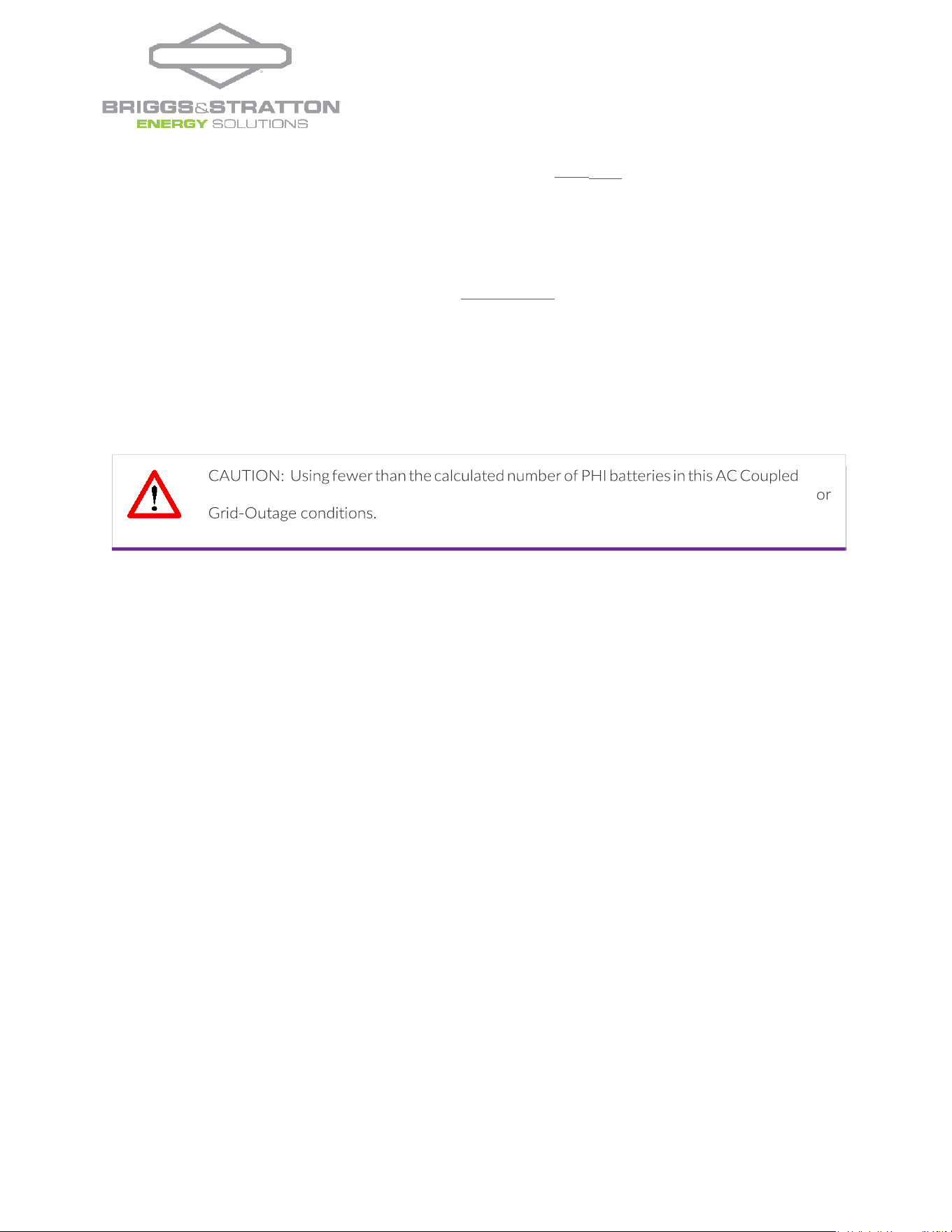
3.2.2
– Additional Sizing Considerations for AC Coupled Systems
In an AC Coupled system, significantly limiting the solar array’s charging power does not work well. In addition,
because the solar charging cycle in an AC coupled system will frequently have minimal absorb time, the level of
charge achievable with a full absorb is not equivalent to the battery’s 100% SoC. This effect is less significant at
slower charging rates. Therefore, Briggs & Stratton recommends sizing a larger battery bank relative to the
AC Coupled PV array. In the below AC Coupling example, the batteries’ typical maximum continuous charge
rate is multiplied by a de-rate factor of 0.8.
The charge calculation uses the nomenclature below:
•
Battery maximum continuous charge rate (kWDC) = BatkW (typically @ C/2)
= (maximum battery charge current × battery voltage nominal)
•
PV charge maximum = PVkW
| 9 |
REV202307060
© 2023 Briggs & Stratton. All rights reserved.
charge calculation may result in limitedly effective charging from AC coupled PV in Off-Grid
Charge
Example:
#
≥
.
×
•
AC Coupled Solar PV Array is rated at 8 kW
•
AmpliPHI 3.8 battery has a maximum continuous charge rate of 1.92 kWDC
#
≥
.
×
.
=
.
A properly sized AmpliPHI battery bank based on the maximum charge from the AC Coupled solar PV array has a
minimum of 6 batteries. This helps ensure that the battery bank receives as much charge as possible from the AC
Coupled solar PV.
When the output of the AC Coupled Solar PV array exceeds the MAX A Charge parameter, and frequency shift is
unable to mitigate the output, the battery charging will be interrupted. To avoid this, PV Array sizing needs to be adjusted
to accommodate the MAX A Charge parameter for the overall system.
Homeowners with little to no loads on during the day (while solar power production is at its peak) might consider sizing
a larger AmpliPHI battery bank to take advantage of the entire solar PV output potential for battery charging.
Homeowners that consistently power loads during peak solar power production times may require a smaller sized
battery bank.
4.0
– Installation
4.1
– Installation Options
The AmpliPHI 3.8 Batteries can be mounted in practically any orientation (terminals up or on any side), with no impact to
the performance of the AmpliPHI Battery. Do not install them upside down, with the terminals facing the floor. A
maximum of 40 AmpliPHI batteries can be connected together via their communications cables to an approved
inverter.
4.2
– Environmental Considerations
4.2.1
– Charging at Temperatures Below Freezing
The AmpliPHI Battery’s internal BMS and protective circuitry prevent it from charging below 32° F (0° C) and
discharging below -4° F (-20° C), unless connected to an approved inverter. Therefore, Briggs & Stratton
recommends installing the battery in conditions where ambient temperature does not drop below freezing in
order to maintain AmpliPHI battery system operability.
| 10 |
REV202307060
© 2023 Briggs & Stratton. All rights reserved.
CAUTION: Do not combine AmpliPHI Batteries with other brands, chemistries, or models
(including the standard PHI model batteries). Do not mix AmpliPHI Batteries from different
installations, clients or job sites. Either of these combinations will void the warranty.
4.2.2
– Explosive Gas Precautions
AmpliPHI Batteries are not ignition protected. To prevent fire or explosion, do not install this product in
locations that require ignition-protected equipment. This includes any confined space containing vented
batteries, or flammable chemicals such as, natural gas (NG), liquid petroleum gas (LPG) or gasoline
(Benzine/Petrol).
Do not install in a confined space with machinery powered by flammable chemicals, or storage tanks, fittings, or
other connections between components of fuel or flammable chemical systems.
AmpliPHI Batteries do not vent any harmful gasses and do not require special
ventilation or cooling.
4.2.3
– Anti-Corrosion Protection
Anticorrosive compounds or epoxies are occasionally used in harsh or marine climate installations. Please
consult your electrician or qualified installer to determine if this is advisable, and if so, what solution best suits
your application.
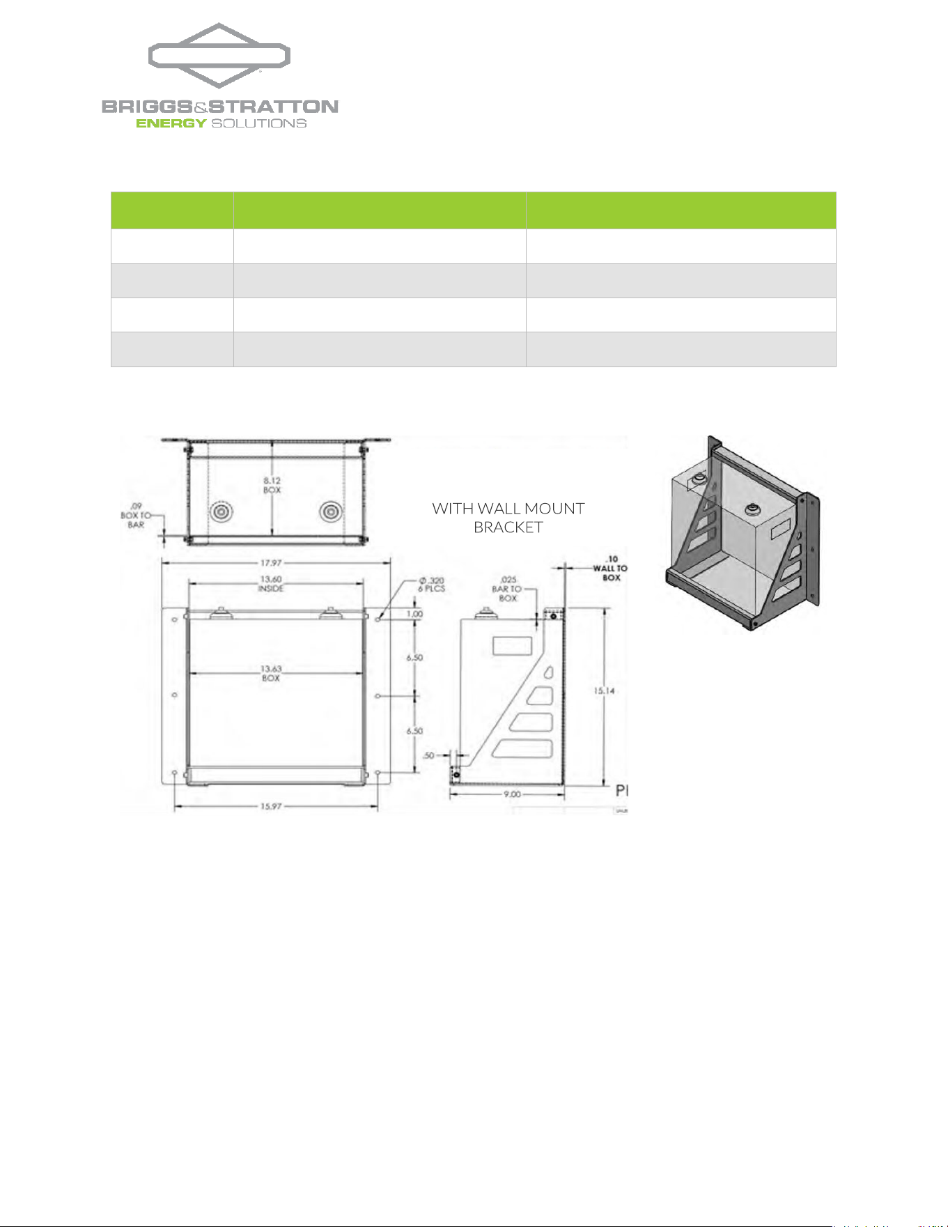
4.3
– Mounting Hardware
AmpliPHI Battery mounting brackets (sold separately) are designed to secure one AmpliPHI 3.8 to a load bearing
surface. The brackets can be mounted directly to a wall or can be arranged on strut channels for ease of positioning
(mounting hardware not included). Mounting brackets should be mounted into load bearing beams, studs or solid
materials with appropriate fasteners. A qualified installer should be familiar with accomplishing this with the
appropriate load bearing requirements. Briggs & Stratton is not liable for damage caused by the inappropriate
installation of mounting of brackets. Refer to Table 2.0 and Figure 2.0 for AmpliPHI Battery and mounting bracket
dimensions and weights.
During mechanical testing, individual AmpliPHI 3.8 Mounting Brackets were exposed to 200 pounds each of downward
pressure along the bracket’s outer edge. During this test, a deflection of approximately 30 thousandths of an inch was
measured. Bracket sets are designed to hold one AmpliPHI 3.8 Module with a weight of 86 pounds.
CAUTION If the AmpliPHI Battery must be charged below 32° F (0° C), the rate of charge must
be at no more than 5% of the PHI Battery’s rated capacity (C/20), or be connected to an
approved battery. Not doing so will void the warranty.
| 11 |
REV202307060
© 2023 Briggs & Stratton. All rights reserved.
AmpliPHI 3.8 Battery
4.4
– Dimensions and Weight
Table 2.0 – Specifications: AmpliPHI 3.8 Battery w/ Mounting Bracket
AmpliPHI 3.8 Battery
Ampli PHI 3.8 Battery
w/ Mounting
Bracket
Widt
h
13.5’’
13.7” (18” with mounting flanges)
Heigh
t
15.5’’ (including 1.5” terminal height)
15.75” (including 1.5” terminal height)
Dept
h
8”
9”
Weig
ht
78.2 Pounds
86.2 pounds
Figure 2.0 – AmpliPHI 3.8 Mounting Bracket Assembly
4.5
– AmpliPHI Battery Connection Terminals
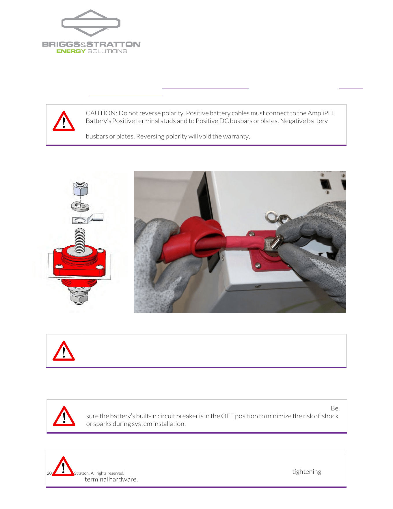
4.5.1
– Batteries with Threaded Studs
The AmpliPHI Battery is equipped with two 3/8’’ (10 mm) threaded studs with a lock washer and nut. The red
colored high temperature molded insert connection is for the positive lead. The black colored high temperature
insert connection is for the negative lead.
Water resistant cable boots are also included and will be in place when your units arrive. The boots are to be
placed over the cable terminations and will stretch to form a water-resistant seal around the base of the molded
inserts and terminal connections.
| 12 |
REV202307060
© 2023 Briggs & Stratton. All rights reserved.
series will result in damage to the AmpliPHI Battery’s protective circuitry and will void the
warranty. AmpliPHI batteries are designed for parallel wiring only to increase the battery
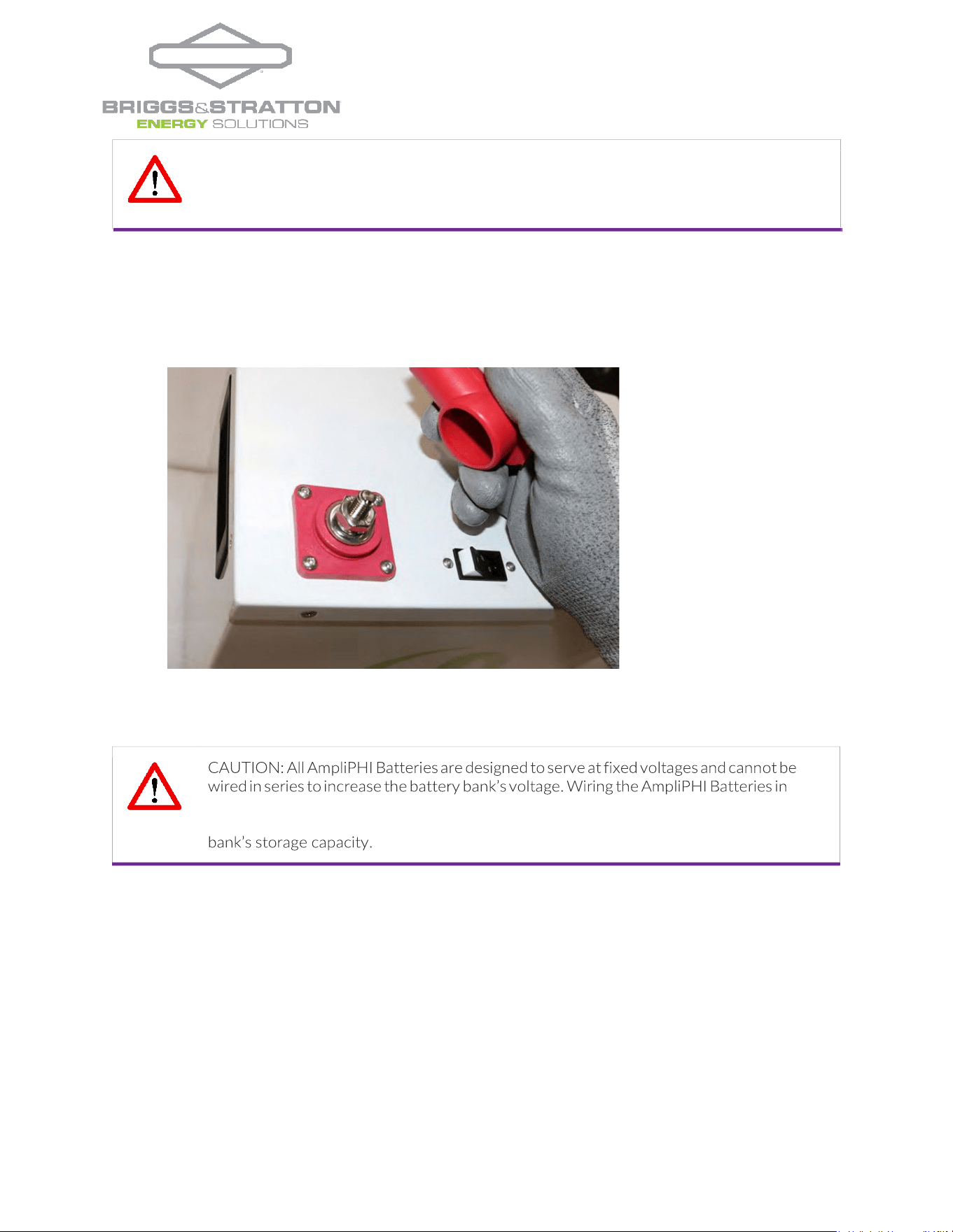
4.5.2
– Torque Batteries with Threaded Studs
AmpliPHI Batteries with threaded stud terminals have a torque specification of 121 in-lbs. (13.3 ft- lbs.).
Figure 3.0 – AmpliPHI Threaded Stud
Threaded Studs = 3/8” (10mm)
Torque Value = 160 in-lbs
4.6
– Electrical Wiring
4.6.1
– Increasing Storage Capacity via Parallel Wiring
Storage Capacity and total available Amperage is increased incrementally with the number of units
wired in
Parallel. For example, two AmpliPHI 3.8 kWh-51.2V
nominal
(75Ah) Batteries wired in parallel
are rated at a
combined 7.6 total kWh, 51.2 Volts DC and 150Ah. The two paralleled PHI 3.8 kWh-
51.2V
nominal
batteries have a combined maximum continuous charge and discharge rate of 75 Amps DC
(2 ×
37.5ADC).
CAUTION: Using an impact driver or power tools on the terminals will void the warranty. Using
power tools or impact drivers may damage the terminal even if it doesn’t result in breakage.
Only use accurately calibrated and properly adjusted torque wrenches when tightening
terminal hardware.
| 13 |
REV202307060
© 2023 Briggs & Stratton. All rights reserved.
CAUTION: Identical wire lengths and identical wire gauges from each AmpliPHI Battery in an
AmpliPHI Battery bank is a critical feature of parallel power storage systems that must be
adhered to throughout all parallel wiring instructions. Failure to properly wire the AmpliPHI
Batteries in parallel will void the warranty.
4.6.2
– Parallel Wiring Batteries with Threaded Studs using Battery Cables
AmpliPHI Batteries are paralleled by wiring from individual AmpliPHI Batteries to DC busbars or plates, which
may be located in a DC combiner box or the inverter’s power panel.
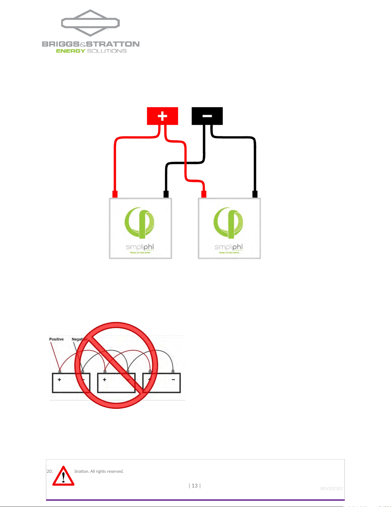
Figure 4.0 – Two AmpliPHI Batteries in Parallel
Although lead acid batteries are typically wired using battery-to-battery interconnecting cables, Briggs & Stratton
asks that AmpliPHI Batteries NOT be wired in this way (in series).
Figure 5.0 – Incorrect AmpliPHI Wiring
All wire lengths from each AmpliPHI Battery to common busbars or plates should be identical in length and gauge in
order to balance the load across (all) AmpliPHI Batteries in the installation.
| 14 |
REV202307060
© 2023 Briggs & Stratton. All rights reserved.
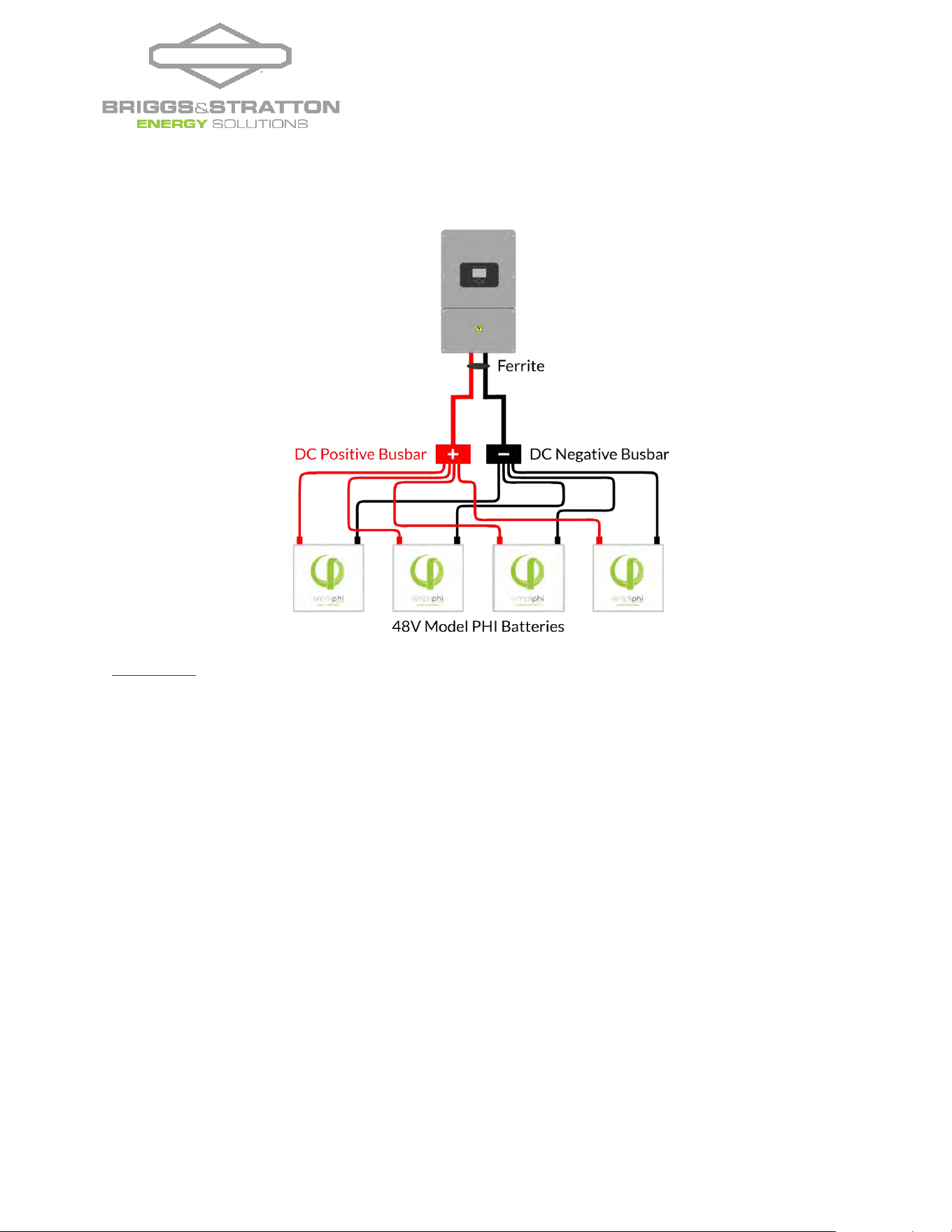
Figure 5.0 depicts three AmpliPHI Batteries wired in Parallel to a terminal block. This configuration requires
8 identical lengths of identical gauge copper wire.
Figure 6.0 - Four PHI Batteries in Parallel
Helpful Tips:
•
Power cabling for paralleling AmpliPHI Batteries is not included. All wire should be an appropriate gauge
and construction to handle the loads that will be placed upon it. Heavy gauge, high strand copper wire is
the industry standard due to its stability, efficiency and overall quality.
•
Each PHI Battery’s individual wire runs are typically sized at 4 AWG, according to the 80A built-in breaker.
o
Conductor ampacity can be determined using National Electrical Code tables.
o
Depending on the electrical code of the local Authority Having Jurisdiction (AHJ), the
AmpliPHI Battery leads’ gauge may need to be sized according to the built-in breaker or
according to the AmpliPHI Battery’s surge rating.
o
Battery cables from Spartan Power are flexible and easy to work with:
https://spartanpower.com/product/custom-battery-cables/. Many of Briggs & Stratton’s
distributors also sell battery cables. Refer to the Briggs & Stratton Wiring Guide for a list of
distributors that sell cables.
•
Battery cables can be custom ordered to include the 3/8” lugs that fit on the AmpliPHI Battery’s threaded
studs.
•
Determine the cable length for the AmpliPHI Battery terminal farthest from the common busbar or plate
first.
•
Additional cabling or slack that remains with the shorter distance runs can be coiled and secured with Zip
Ties.
•
Wire length should be kept as short as practical.
•
Positive wire runs should be separated from negative wire runs in separate conduit.
•
Energy supplied by the AmpliPHI Battery is reduced as electrical current moves through wire. For lengths
of battery cable greater than ~10 feet (3 meters), ensure that the voltage drop is no greater than 3%.
| 15 |
REV202307060
© 2023 Briggs & Stratton. All rights reserved.
cables must connect to the AmpliPHI Battery’s Negative terminal studs and to Negative DC
CAUTION: No material (such as a washer) should be placed between the current carrying
terminal and the cable lug or interconnecting busbar.
Doing so will void the warranty.
CAUTION: Sparks may be present when connecting wires to AmpliPHI Battery terminals.
CAUTION: Using an impact driver or power tools on the terminals will void the warranty. Using
power tools or impact drivers may damage the terminal even if it doesn’t result in breakage.
Only use accurately calibrated and properly adjusted torque wrenches when
•
To take full advantage of the combined AmpliPHI Battery bank’s surge rating, the DC busbars or plates
that the individual AmpliPHI Batteries are wired to should be rated to match the AmpliPHI Battery bank’s
total surge rating.
•
MidNite Solar produces the MNLB Lithium Battery Combiner (rated at 250 Amps MAX) and the MNBCB
1000/50 Battery Combiner (rated at 1,000 Amps MAX)
Figure 7.0 – Cable Lug Wiring onto AmpliPHI Threaded Stud
| 16 |
REV202307060
© 2023 Briggs & Stratton. All rights reserved.
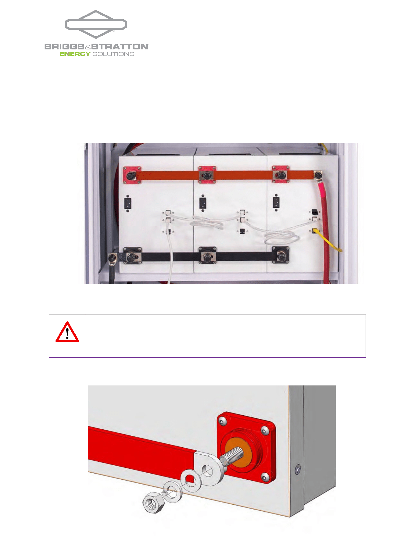
CAUTION: Again, no material (such as a washer) should be placed between the current
carrying terminal and the interconnecting busbars. The interconnecting busbars are placed on
the AmpliPHI Batteries’ terminals first, then the flat washer, lock washer, and nut are secured
to the terminal posts.
4.6.3
– Parallel Wiring Batteries with Threaded Studs using Interconnecting Busbars
AmpliPHI Batteries can be paralleled using common bussing directly attached to the batteries’ terminals.
Interconnecting busbars for paralleling either two (SKU #BB-2) or three (SKU #BB-3) AmpliPHI batteries with threaded
studs are available from Briggs & Stratton at an additional cost.
Figure 8.0 – AmpliPHI Wiring using Interconnecting Busbars
Figure 9.0 – Interconnecting Busbar Wiring onto AmpliPHI Threaded Stud
| 17 |
REV202307060
© 2023 Briggs & Stratton. All rights reserved.
CAUTION: Do not reverse polarity. Use a voltmeter to check polarity before making
connections to the battery terminals. Reversing polarity will void the warranty.
CAUTION: The maximum number of AmpliPHI batteries that can be installed within a single
bank is 40.
Helpful Tips:
•
The interconnecting busbars’ ratings should match or exceed the AmpliPHI Battery bank’s total surge
rating.
•
Busbars for paralleling more than two or three AmpliPHI Batteries can be sourced from outside
suppliers or custom ordered from Briggs & Stratton.
•
Briggs & Stratton recommends paralleling AmpliPHI Batteries using interconnecting busbars (not battery
cables) for AmpliPHI Battery Banks consisting of more than 20 batteries for a cleaner installation.
•
Best practice involves wiring the battery leads to opposite ends of the busbars.
•
Size the battery cables leading from the interconnecting busbars to the Balance of System equipment
using the National Electrical Code’s Conductor Ampacity tables.
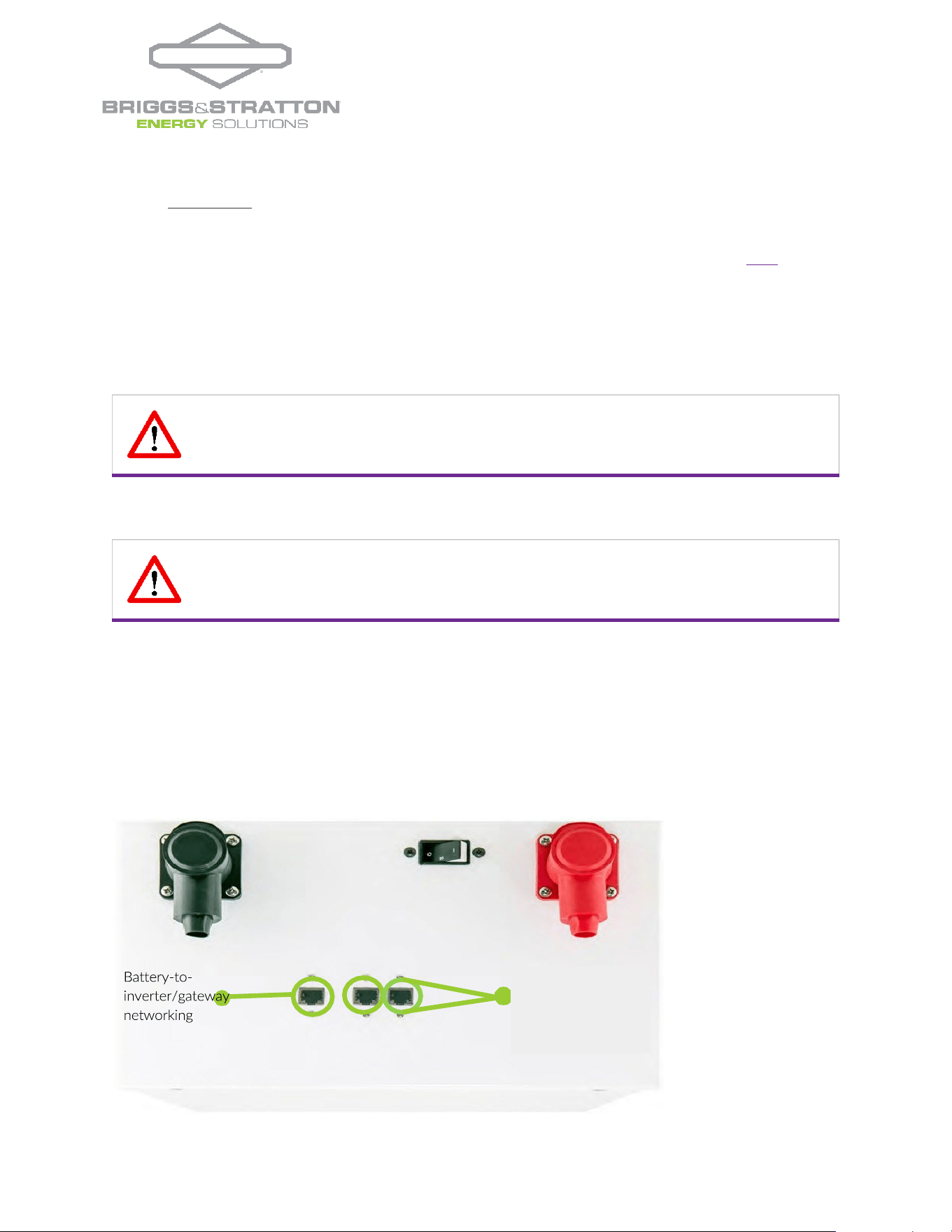
4.7
– Communications Wiring
Each AmpliPHI battery includes three RJ45 ports, compatible with CAT5 (or greater) cable. Two of these ports are used for
connecting between the AmpliPHI batteries in a battery bank (“daisy-chaining”). These two ports can be identified as the “daisy-
chaining” ports because they are near one another. The third port is used for the communications connection between the
AmpliPHI battery bank and the inverter. Only one of the AmpliPHI batteries within the battery bank will utilize this third port
(either the battery at the head or the tail of the daisy- chain). AmpliPHI batteries with un-utilized third ports may plug those
ports using the RJ45 dust caps provided with the battery.
Figure 10.0 – AmpliPHI Networking Connection Ports
connection port
Daisy-chaining
ports for battery-
to-battery
networking
| 18 |
REV202307060
© 2023 Briggs & Stratton. All rights reserved.
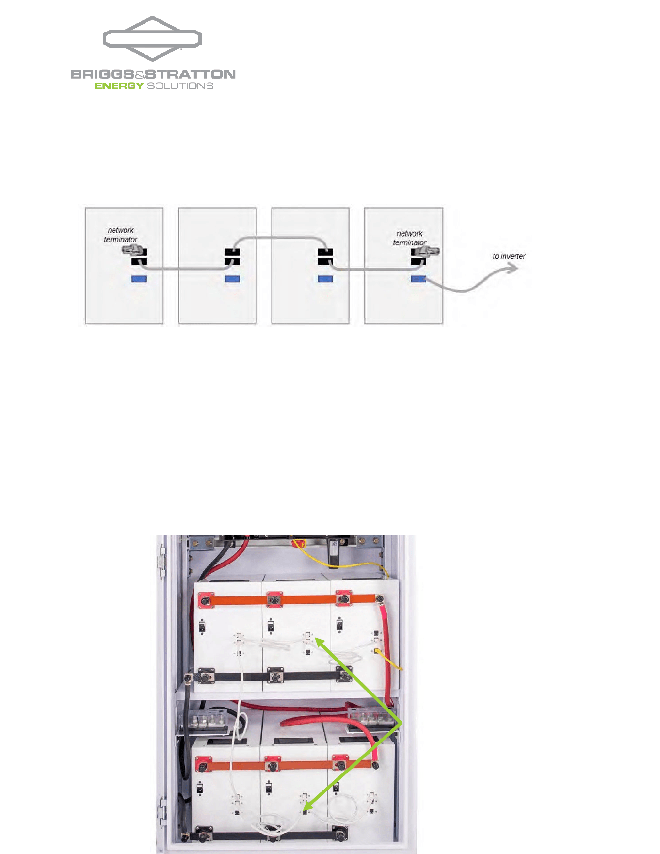
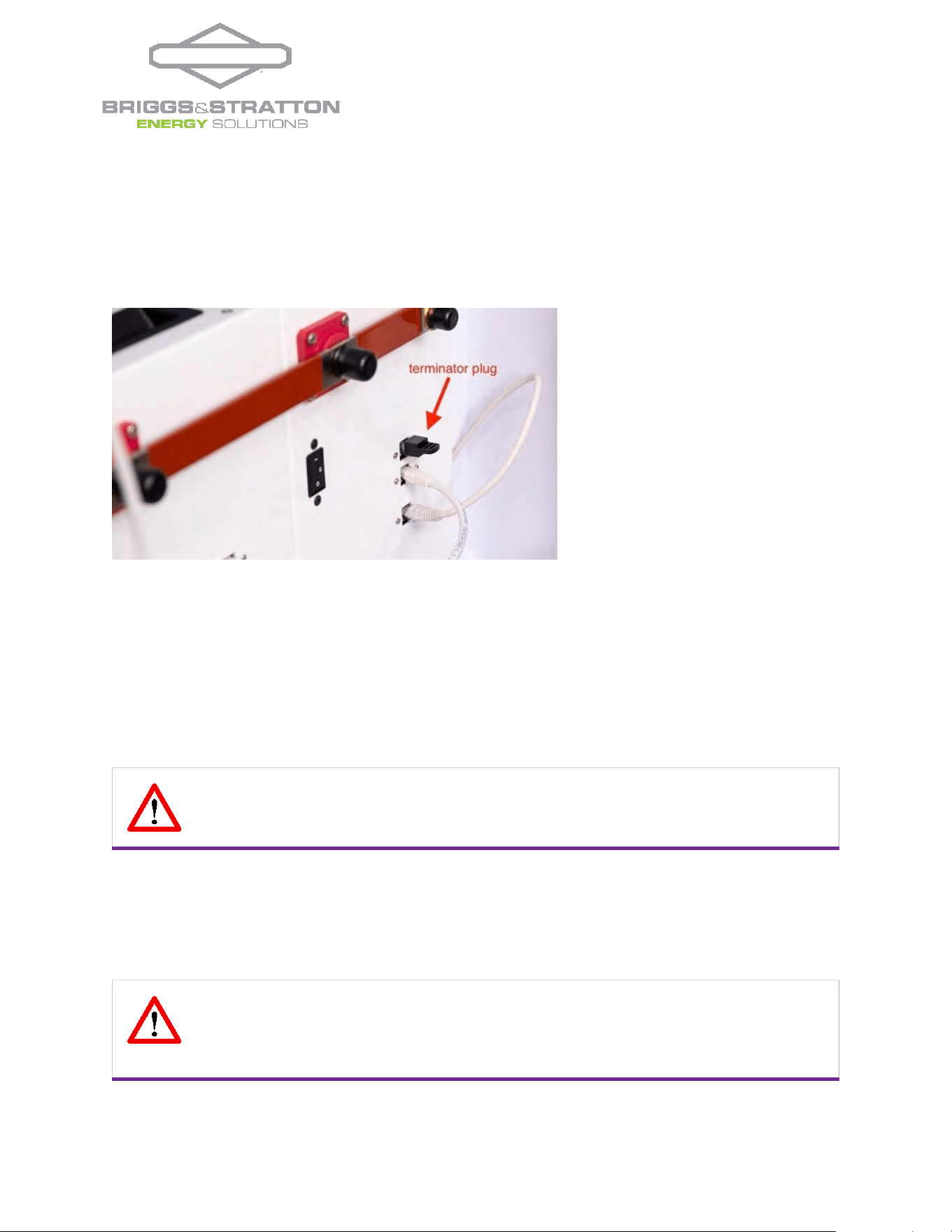
In a string of batteries, the two batteries at the ends of the communication chain will have a cable occupying only one of
the “daisy-chaining” ports in the AmpliPHI battery. On each of these two batteries, the communication port not
occupied by a cable will need a 120Ohm terminator plug installed in the open port (see photo). One terminator plug is
included per AmpliPHI battery.
Figure 11.0 – AmpliPHI Batteries Networked Together in a Daisy-Chain
Figure 12.0 – AmpliPHI Batteries Networked
| 19 |
REV202307060
© 2023 Briggs & Stratton. All rights reserved.
CAUTION: AmpliPHI Batteries should be installed, wired and commissioned by a qualified
installer or professional electrician who is familiar with general electrical safety precautions
and specific regional code requirements.
CAUTION: Only use a Briggs & Stratton approved LFP charger if ancillary charging is
required before installation, testing or troubleshooting. Failure to use a Briggs & Stratton
approved LFP charger will damage the AmpliPHI Batteries and void the warranty. See
Appendix C for more details on approved chargers.
Figure 13.0 – AmpliPHI Battery’s Terminator Plug
The maximum number of AmpliPHI batteries that can be connected in a single system is 60, with a maximum total connected
distance of 40m (131 feet) from the first AmpliPHI battery module to the last AmpliPHI battery module. While one 4’ CAT5
networking cable is provided per AmpliPHI battery, shorter networking cable for daisy-chaining the batteries may be used.
Utilizing the last/closest battery to the inverter, create the closed loop communications bridge between the AmpliPHI Battery
and the Communication Input Port in compatible equipment utilizing CAT5 or greater cable. The cable length from the last
AmpliPHI Battery to the Inverter cannot exceed 40m (131 feet).
4.8
– Battery System Commissioning
If the AmpliPHI Battery’s voltage has dropped (during an extended period in storage) to a voltage below the inverter’s minimum
starting voltage requirement, then the battery will need to be charged using a plug-in / external charger.
Briggs & Stratton’s b
atteries have a very low self-discharge rate and typically do not require ancillary charging. If the AmpliPHI
Battery’s voltage has dropped due to over-discharge, try the steps outlined in Section 6.0 – Troubleshooting prior to using
ancillary charging equipment.
1.
Before installing the AmpliPHI Battery, inspect the battery for any signs of damage. Do not install or operate the
| 20 |
REV202307060
© 2023 Briggs & Stratton. All rights reserved.
CAUTION: All Briggs & Stratton Battery products are designed to work exclusively in
parallel. Never connect in series to achieve higher voltages. Wiring in series will destroy the
batteries and void the warranty.
Verify polarity at all connections before energizing system. Reverse polarity at the AmpliPHI
Battery terminals will destroy the AmpliPHI batteries and void the warranty.
CAUTION: Briggs & Stratton Batteries must operate in conjunction with properly
programmed Balance of System equipment. Operating the batteries with equipment that has
not been programmed to Briggs & Stratton’s specified parameters will damage the AmpliPHI
batteries and void the warranty.
CAUTION: Charge the batteries fully. When first commissioning the battery system, the
batteries must be charged fully before connecting any loads. Neglecting to charge the
batteries fully when first commissioning the battery system will void the warranty.
battery if it has been damaged during shipping.
2.
Prepare the battery module for installation by removing its plastic terminal covers, 11/16” stainless steel hex nuts
and 3/8” lock washers from the battery terminals and set aside.
3.
4. Before installing the AmpliPHI Battery, test its voltage by turning its built-in breaker to the ON (I) position.
5. Measure the AmpliPHI Battery’s voltage with a multimeter. Batteries typically ship at ~52 VDC.
6. When installing more than one AmpliPHI Battery, check that the batteries’ voltage readings are similar. Batteries with a
voltage variance greater than 1 Volt DC should be isolated and charged separately.
7. After testing the AmpliPHI Battery’s voltage, turn the battery’s built-in circuit breaker back to the OFF (0) position.
8. Wire the AmpliPHI Battery bank with all the included AmpliPHI Batteries’ built-in breakers in the OFF (0) position. All
electrical wiring must be in accordance with Section 4.6 – Electrical Wiring and all communications wiring must be in
accordance with Section 4.7 – Communications Wiring.
4.
Confirm all loads are turned OFF. Disconnect the inverter’s AC Output breaker or turn off the breaker at the top of
your loads’ breaker panel.
5.
The main DC disconnect in the inverter’s power panel should still be in the OFF position.
6.
Turn all battery circuit breaker switches to the ON (I) position and wait 20 seconds for the BMS to re-boot.
7.
Turn the main DC disconnect in the inverter’s power panel ON.
8.
At this point, the inverter may come on automatically in standby mode, or the inverter might need to be manually
turned on.
9.
Activate the AmpliPHI Battery’s networking connection within the Balance of System (BoS) equipment. Then
program the equipment for those settings that are not automatically communicated by the AmpliPHI to the BoS
equipment. Briggs & Stratton’s settings are specified in the relevant AmpliPHI Integration Guides specific to the
inverter you are utilizing. (https://simpliphipower.com/product-documentation/) and are generally outlined in
Section 5.0 – Programming of this Manual.
CAUTION: Do not attempt to loosen the large brass nut at the base of the terminals; doing so
will damage the AmpliPHI battery and void the warranty.
| 21 |
REV202307060
© 2023 Briggs & Stratton. All rights reserved.
CAUTION: Do not combine PHI Batteries with other brands or chemistries. This will void the
warranty.
10.
Battery charging may be accomplished via the inverter/charger using an AC power source such as the grid or a
generator, or via a charge controller using power from a connected solar PV array.
11.
Battery charging may be accomplished via the inverter/charger using an AC power source such as the grid or a
generator, or via a charge controller using power from a connected solar PV array.
12.
The batteries will bulk charge to 56 VDC, will Absorb for 0.6 hours, and will then rest at approximately 53.3 VDC. At
this point in the charging cycle, these voltages (53.3V) are considered 100% SOC.
13.
Once the batteries are fully charged, turn on the inverter’s AC Output breaker and/or the breaker at the top of your
loads’ breaker panel.
4.9
– Battery Bank Expansion
New Briggs & Stratton Batteries that are added to an existing Briggs & Stratton battery bank must be of the same
nameplate voltage, form factor, and model.
The following are instructions for expanding upon an AmpliPHI battery bank using AmpliPHI batteries.
In addition to adhering to all other Installation Manual instructions, refer to the following guidelines when expanding
upon an existing AmpliPHI battery bank:
1. Charge the existing battery bank (“Bank A”) according to normal charging procedure (AmpliPHI batteries charge to
56V and “rest” at approximately 52.5 - 53.5V after being taken off a charge).
2. Disconnect Bank A from the system, by either
3. Disconnecting all battery cables leading from Bank A’s batteries to the battery combiner box, panelboard, or
inverter’s power panel, OR
4. Turning off the built-in breakers included in each of Bank A’s batteries
5. Connect the additional batteries (Bank B) to the system, following all wiring instructions and torque specifications
outlined in previous sections of segment 4.0 in this manual.
6. Check that the connected Balance of System (BoS) equipment settings (including charge rate) are altered as a result
of being networked to Bank B.
7. Charge Bank B fully, making sure all loads are disconnected at the time of initial charge.
8. Wire all Bank A batteries and Bank B batteries in parallel, adhering to the wiring methods outlined in Sections 4.6
and 4.7 above.
9. Ensure that DC Positive common bus and DC Negative common bus ratings are appropriate for the new larger
quantity of batteries in the bank.
10. Remember to re-orient the networking connections as one long “daisy-chain” for the expanded battery bank. This
will involve unplugging the last terminator plug in the chain and reposition to the end of the “daisy-chain” and
reconnecting the battery-to-inverter communications cable and reviewing all BoS equipment settings for accuracy.
11. Review all BoS equipment settings for accuracy; new values for certain settings should automatically appear as reflective
of the larger, expanded battery bank.
CAUTION: Remember that charging the batteries in sub-freezing conditions will void the
warranty.
| 22 |
REV202307060
© 2023 Briggs & Stratton. All rights reserved.
CAUTION: When commissioning the system, the appropriate controller and inverter settings
must be programmed per the manufacturer’s recommendations. Consult the manufacturer’s
manuals and/or the Integration Guides listed on Briggs & Stratton’s P
roduct Documentation web
page. Failing to do so will damage the AmpliPHI batteries and will void the warranty. The
following
Charge Controller Integration tables are for general reference only.
5.0
– Programming
5.1
– Operating Parameters per warranty
To maintain AmpliPHI Battery health and to comply with the warranty, adhere to the operating parameters outlined in
Tables 4.0 and 5.0 below. Refer to the manufacturer-specific Integration Guide from Briggs & Stratton’s Product
Documentation web page for a complete list of settings specific for the inverter that you are pairing with:
https://simpliphipower.com/product-documentation/.
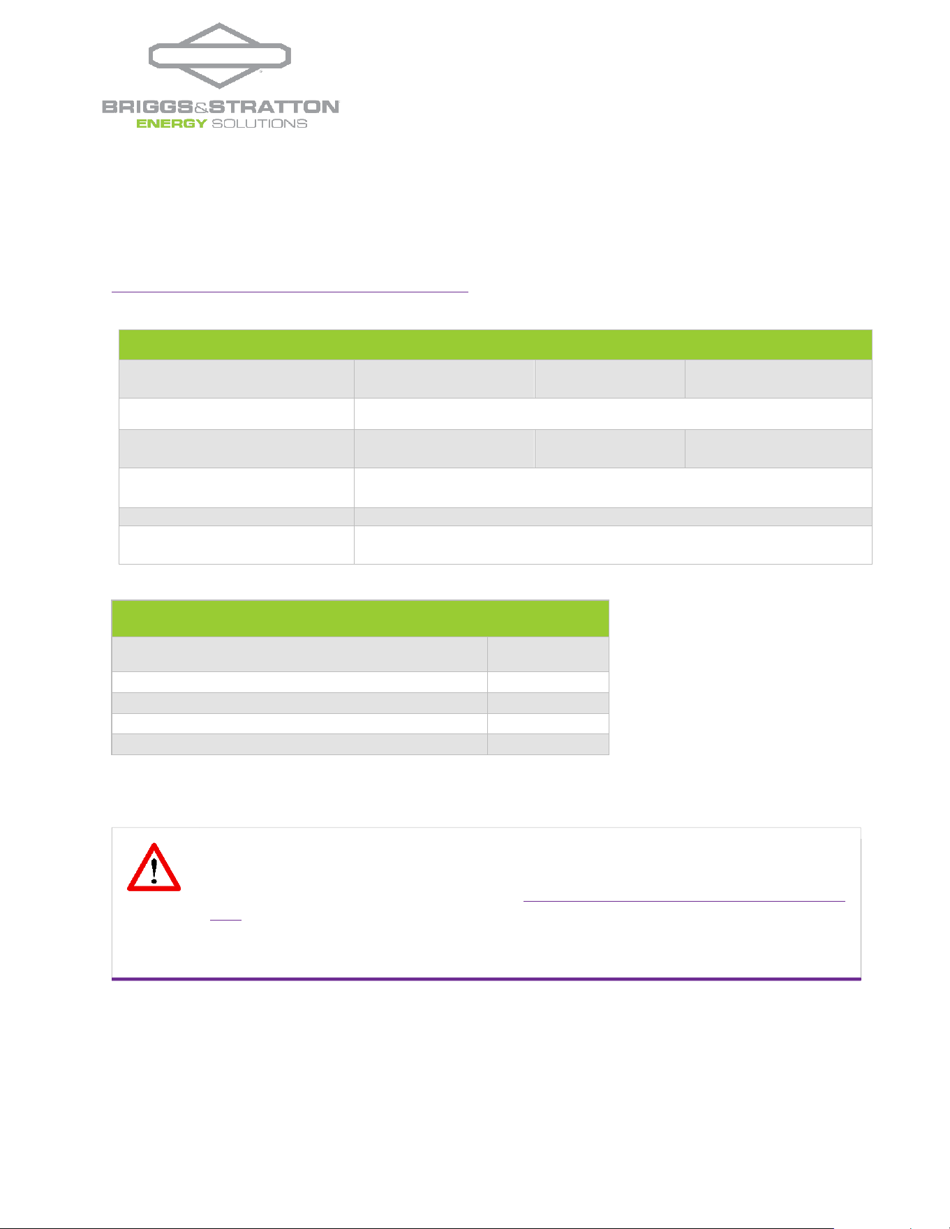
Table 4.0 – Operation Parameters
Recommended Operating Conditions for 10 Year warranty
Depth of Discharge (DoD)
80%
(~10,000
cycles)
90%
(~5,000
cycles)
100%
(~3,500
cycles)
Operating Temperature °F
(°C)
32 to 120 (0 to 49) / Optimal 77 to 95 (25 to 35) internal battery temperature
Low Battery Cut-Off Voltage
(V)
3
50.2 49.6
48
Absorb / High Cut-Off
Voltage (V)
56
Absorb Time
0.1 Hours
Absorb End Amps (if
applicable)
2% of the PHI Battery bank’s total Ah capacity
Table 5.0 – Operating Limitations
Notes / Operating Limitations for AmpliPHI Batteries
AmpliPH
I 3.8
Limitations by Model
48V
Continuous Discharge Rate (ADC)
37.5
Surge Discharge Rate (ADC) – 10 minutes maximum
100
Continuous Charge Rate (ADC)
37.5
• Levels are typically @ 25°C and may need adjusting at temperature extremes.
• When performing rapid deep charge/discharge cycles, the batteries should be allowed to "rest" in between.

| 23 |
REV202307060
© 2023 Briggs & Stratton. All rights reserved.
6.0
– Troubleshooting
Certain AmpliPHI BMS fault trip conditions (outlined in Section 1.3.1 and Table 1.0 of this Manual) result in the need for
a manual re-set of your AmpliPHI Battery’s internal BMS. If a fault has occurred, consult Briggs & Stratton Technical
Support (Oxnard-techsupport@basco.com) to ensure that your AmpliPHI Battery bank has been sized correctly and
inhabits operational conditions.
Once the fault’s cause has been addressed with Support, take the following steps to re-set the BMS:
The PHI batteries are reading extremely low or no voltage:
1.
If the breakers are not all off already, turn off each of the built-in breakers in all of the AmpliPHI Batteries in the
battery bank.
2.
Turn off the main DC disconnect located in the inverter’s power panel, between the battery bank and the inverter.
3.
Turn off the main breaker at the top of the inverter’s AC distribution panel or sub-panel.
4.
Wait 5 minutes, for the BMS in each battery to re-set itself.
5.
Use a multi meter to take voltage measurements of each AmpliPHI battery in the battery bank, to make sure the
voltage increased to the minimum voltage necessary for the inverter to turn on.
To measure a single battery’s voltage within a battery bank, only the battery being measured has its built-in breaker in
the ON (I) position; all other batteries in the bank must have their built-in breakers OFF (0).
6.
Turn on each of the built-in breakers in all of the AmpliPHI Batteries in the battery bank and wait 20 seconds for
the BMS to re-boot.
7.
Turn on the main DC disconnect located in the inverter’s power panel.
8.
Check that all parameters in the Balance of System equipment are programmed according to the relevant Briggs
& Stratton Integration Guide. Failure to do so will damage the PHI batteries and void the warranty.
9.
To charge the batteries quickly, Briggs & Stratton recommends using an AC power source to immediately charge
the PHI battery bank via the inverter’s charger. However, the AmpliPHI batteries will not incur any damage if
they are charged using a connected solar PV array via the charge controller. The important aspect of this step is
that the batteries re-charge as soon as the BMS has re-set.
10.
Turn on the inverter’s AC Input breaker and turn on the inverter.
11.
The inverter should automatically self-initiate a battery charge. However, a Force Charge may need to be initiated
in the inverter.

| 24 |
REV202307060
© 2023 Briggs & Stratton. All rights reserved.
Appendix A – SimpliPHI Battery Safety &
Green Attributes, Certifications
This Appendix section covers the AmpliPHI Battery safety attributes and certifications, UN DOT certification and
UL compliance and certification. It also covers the AmpliPHI Battery’s green attributes – from products to materials
to disposal, as well as relevant environmental and ecological considerations.
A.1 – Safety Attributes and Certifications
A.1.1 – Intrinsically Safe Operation and Installation
The SimpliPHI Lithium Ferrous Phosphate (LFP) battery cell component is made with an intrinsically safe cathode
material (iron phosphate). This creates a strong molecular bond, which withstands extreme conditions, prolongs
cycle life, and maintains integrity with little or no maintenance over extended periods of time. No venting or cooling
is required. No special precautions or structural considerations beyond what is in the manual are necessary when
installing AmpliPHI Batteries.
A.1.2 – No Safety Hazards due to Off-Gassing
AmpliPHI Batteries do not vent dangerous gasses during normal operation, such as hydrogen and oxygen, because
chemicals contained in Lithium Ferro Phosphate cells’ electrolyte do not electrolyze to any appreciable extent
within the AmpliPHI Battery’s operating voltage range.
A.1.3 – AmpliPHI Battery Control and Protective Circuitry
AmpliPHI batteries utilize balancing, voltage regulation, thermal and current controls, as well as other protective
measures in its AmpliPHI Battery Management System (BMS). This protective circuitry is embedded in the
architecture of each AmpliPHI Battery.
A.1.4 – UN DOT Certified Cells
The Lithium Ferrous Phosphate (LFP) cells are independently certified to withstand the UN DOT 38.3 testing
guidelines with no special circuitry added. These tests include short circuit, over-voltage, overcharging, extreme
temperature, high altitudes, shock and extreme vibration testing.
A.1.5 – UL Compliance
The Lithium Ferrous Phosphate cells within the AmpliPHI Batteries fully comply with the safety testing parameters
of UL 1642. Batteries have been tested to UL 9540A and are certified to UL 1973.
A.1.6 – RoHS Compliant
AmpliPHI 3.8 Batteries are RoHS compliant. Any RoHS compliant component is tested for the presence of Lead
(Pb), Cadmium (Cd), Mercury (Hg), Hexavalent chromium (Hex-Cr), Polybrominated biphenyls (PBB), and
Polybrominated diphenyl ethers (PBDE). For Cadmium and Hexavalent chromium, there must be less than 0.01% of
the substance by weight at raw homogeneous materials levels. For Lead, PBB, and PBDE, there must be no more
than 0.1% of the material, when calculated by weight at raw homogeneous materials. Any RoHS compliant
component must have 100 ppm or less of mercury and the mercury must not have been intentionally added to the
component. In the EU, some military and medical equipment are exempt from RoHS compliance.