
㻌
㻌
㻌
㻌
RB398S
RB518
RB218
INSTRUCTION MANUAL AND SAFETY INSTRUCTIONS
MODE D'EMPLOI ET CONSIGNES DE SÉCURITÉ
MANUAL DE INSTRUCCIONES E INSTRUCCIONES DE SEGURIDAD
INDEX ENGLISH Page 6 to 17
SOMMAIRE FRANÇAIS Page 18 à 30
ÍNDICE ESPAÑOL Página 31 a 43
REBAR TYING TOOL
OUTIL DE LIGATURE DE BARRES
ATADORA DE ARMADURAS DE REFUERZO
RB398S RB518 RB218
Before using the tool, read and understand tool labels and manual. Failure to
follow warnings could result in serious injury. Keep these instructions with the
tool for future reference.
Veillez à lire et bien comprendre les étiquettes et le manuel avant d'utiliser cet
outil. Tout manquement au respect des avertissements peut entraîner des
blessures graves. Conservez ces instructions avec l'outil pour toute
consultation ultérieure.
Lea y comprenda las etiquetas y el manual de la herramienta antes de usarla.
El incumplimiento de las advertencias puede provocar lesiones graves.
Conserve estas instrucciones junto con la herramienta para futuras consultas.
WARNING
AVERTISSEMENT
ADVERTENCIA
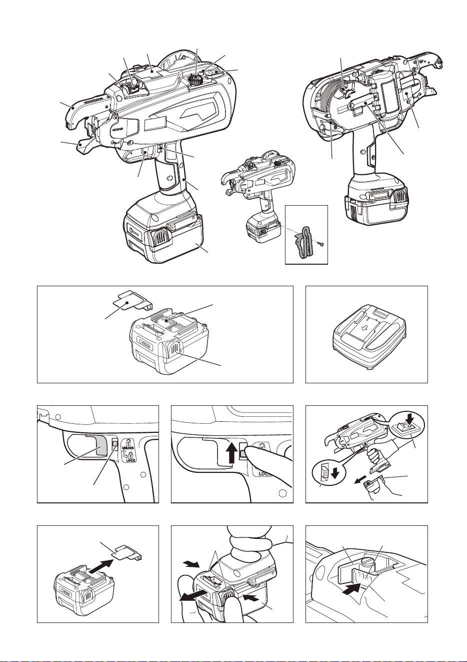
Fig.4 Fig.5
Fig.7 Fig.8 Fig.9
⑱
⑩
②③
Fig.2 Fig.3
Fig.1
⑭
⑬
⑯
⑮
⑫
①
②
③
④
⑤
⑥
⑦
⑧
⑪
⑨
⑩
⑱
⑲
Fig.6
⑧
⑦
⑩
⑪
⑧
⑲
⑳
⑰
2
⑤
23
⑧
22
②
③
Fig.10 Fig.11 Fig.12
Fig.13
Fig.14 Fig.15
Fig.16 Fig.17 Fig.18
Fig.19 Fig.20 Fig.21
⑯
⑭
⑯
⑭
23
24
22
45°
Fig.22 Fig.23 Fig.24
⑬
⑬
⑬
⑬
⑬
3
a
①
25
Fig.25 Fig.26
26
29
27
28
Fig.27
Fig.28 Fig.29 Fig.30
Fig.31 Fig.32 Fig.33
Fig.34 Fig.35 Fig.36
30
27
26
28
29
24
30
32
33
29
31
28
26
27
25
25
b
c
4
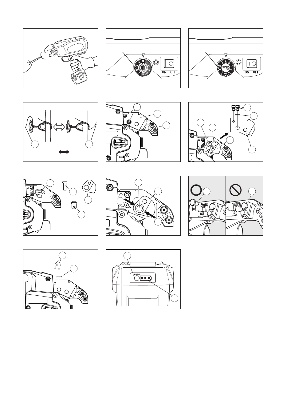
Fig.37 Fig.38 Fig.39
Fig.40 Fig.41 Fig.42
Fig.43 Fig.44 Fig.45
Fig.46
41
35
⑤
⑤
110
34
34
35
36
37
39
38
40
36
42
38
40
39
39
40
44
43
35
41
38 38
Fig.47
45
46
5

6
INDEX
1. NAME OF PARTS ............................................................................................................................................. 6
2. LIST OF CONTENTS......................................................................................................................................... 7
3. GENERAL POWER TOOL SAFETY WARNINGS............................................................................................7
4. RB398S/RB518/RB218 SAFETY FEATURES.................................................................................................. 8
5. TOOL SPECIFICATIONS AND TECHNICAL DATA ...................................................................................... 10
6. TECHNICAL DATA ......................................................................................................................................... 11
7. PRODUCTION YEAR...................................................................................................................................... 11
8. WIRE SPECIFICATION................................................................................................................................... 12
9. APPLICATIONS .............................................................................................................................................. 12
10. APPLICABLE REBAR SIZE ........................................................................................................................... 12
11. BATTERY INSTRUCTIONS ............................................................................................................................ 13
12. OPERATING INSTRUCTIONS........................................................................................................................ 14
13. MAINTENANCE............................................................................................................................................... 15
14. CLEANING MANUAL...................................................................................................................................... 15
15. STORAGE ....................................................................................................................................................... 15
16. TROUBLE SHOOTING/REPAIRS................................................................................................................... 16
DEFINITIONS OF SIGNAL WORDS
WARNING: Indicates a hazardous situation which, if not avoided, could result in death or serious injury.
CAUTION: Indicates a hazardous situation which, if not avoided, could result in minor or moderate injury.
NOTICE: Indicates a property damage message.
1. NAME OF PARTS
Fig.1
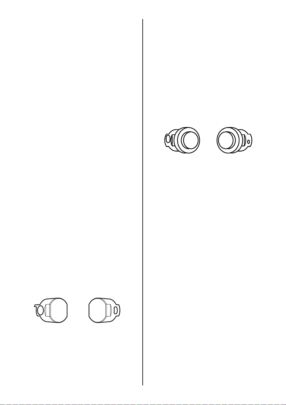
Fig.2 Battery pack
Fig.3 Battery charger
Refer to the JC925A operating and maintenance manual.
Fig.13 to Fig.47
ENGLISH
INSTRUCTION MANUAL AND SAFETY INSTRUCTIONS
1 Arm
2 Release stopper
3 Release lever
4 Window
5 Torque dial (RB398S)
Torque and wrap dial (RB518)
Feed dial (RB218)
6 LED
7 Main switch
8 Trigger lock
9 Grip
0 Battery pack
a Trigger
b Curl guide
c Tiewire
d Reel stopper
e Production year and number
f Reel holder
g Belt hook
h Latch
i Pack cap
j Terminal
l Feeding gear
m Wire Guide
n Pipe
o Hexagon socket head bolts M3 × 6
p Cutter
q Wire guide A
r Fixed cutter
s Cutter plate unit
Original instructions
7
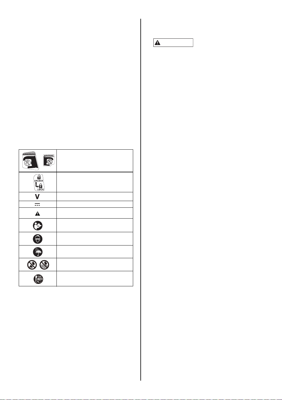
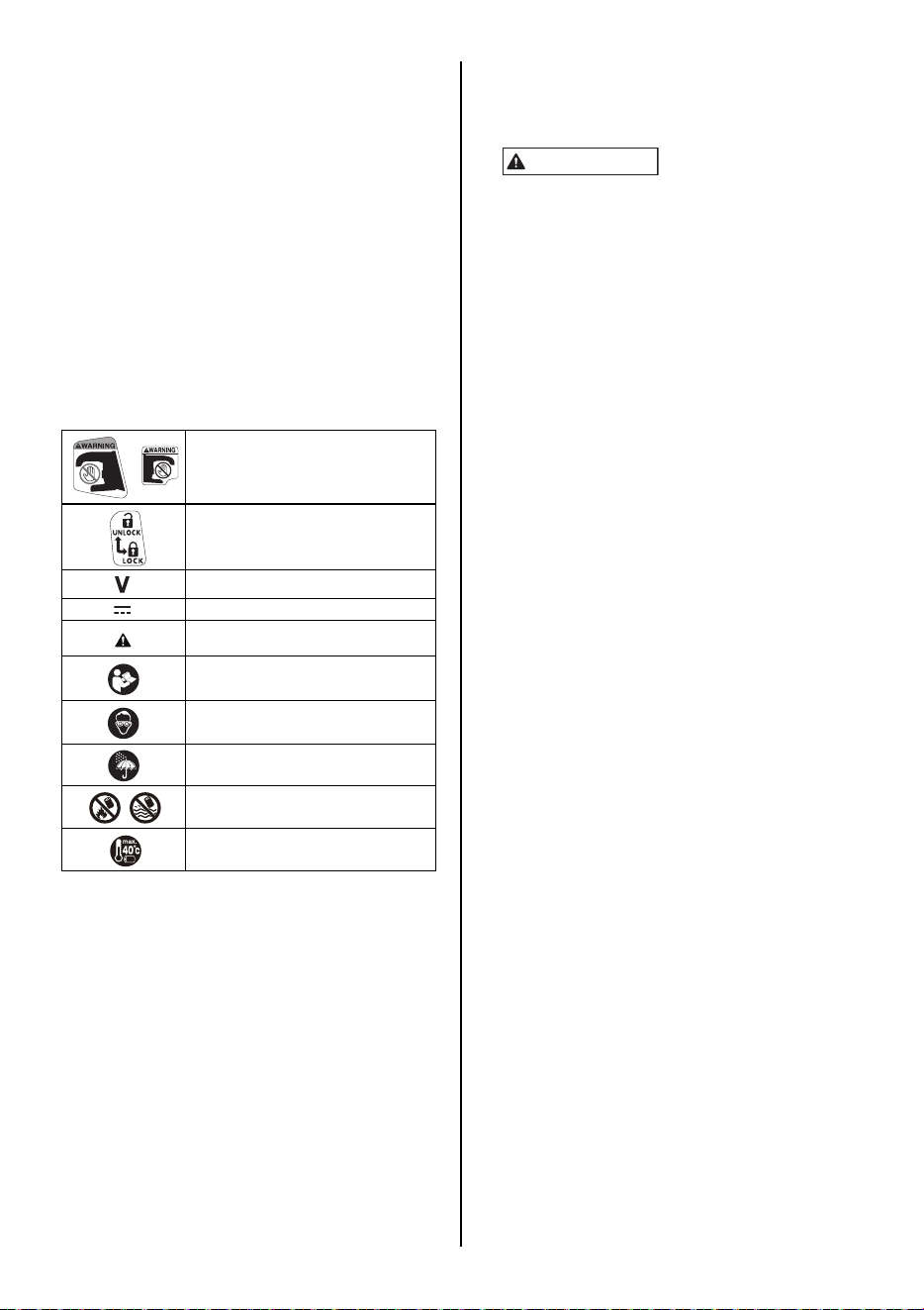
Symbols
The following show symbols used for the machine.
2. LIST OF CONTENTS
• MAX REBAR TYING tool / RB398S/RB518/
RB218
• Lithium ion Battery pack / JPL91450A
• Lithium ion Battery charger / JC925A
• Power cord
• Belt hook
• INSTRUCTION MANUAL AND SAFETY
INSTRUCTIONS (This book)
3. GENERAL POWER TOOL SAFETY
WARNINGS
1. Work area safety
• Keep work area clean and well lit. Cluttered or dark
areas invite accidents.
• Do not operate power tools in explosive atmospheres,
such as in the presence of flammable liquids, gases
or dust. Power tools create sparks which may ignite the
dust or fumes.
• Keep children and bystanders away while operating a
power tool. Distractions can cause you to lose control.
2. Electrical safety
• Power tool plugs must match the outlet. Never modify
the plug in any way. Do not use any adapter plugs
with earthed (grounded) power tools. Unmodified plugs
and matching outlets will reduce risk of electric shock.
• Avoid body contact with earthed or grounded
surfaces, such as pipes, radiators, ranges and
refrigerators. There is an increased risk of electric shock
if your body is earthed or grounded.
• Do not expose power tools to rain or wet conditions.
Water entering a power tool will increase the risk of
electric shock.
• Do not abuse the cord. Never use the cord for
carrying, pulling or unplugging the power tool. Keep
cord away from heat, oil, sharp edges or moving
parts. Damaged or entangled cords increase the risk of
electric shock.
•
When operating a power tool outdoors, use an
extension cord suitable for outdoor use.
Use of a cord
suitable for outdoor use reduces the risk of electric shock.
• If operating a power tool in a damp location is
unavoidable, use a residual current device (RCD)
protected supply. Use of an RCD reduces the risk of
electric shock.
3. Personal safety
•
Stay alert, watch what you are doing and use common
sense when operating a power tool. Do not use a power
tool while you are tired or under the influence of drugs,
alcohol or medication.
A moment of inattention while
operating power tools may result in serious personal injury.
• Use personal protective equipment. Always wear eye
protection. Protective equipment such as a dust mask,
non-skid safety shoes, hard hat or hearing protection used
for appropriate conditions will reduce personal injuries.
• Prevent unintentional starting. Ensure the switch is in
the off-position before connecting to power source
and/or battery pack, picking up or carrying the tool.
Carrying power tools with your finger on the switch or
energising power tools that have the switch on invites
accidents.
• Remove any adjusting key or wrench before turning
the power tool on. A wrench or a key left attached to a
rotating part of the power tool may result in personal
injury.
• Do not overreach. Keep proper footing and balance at
all times. This enables better control of the power tool in
unexpected situations.
t Arm B
u Cutter connecting rod hole
v groove
w Wire guide B
x edge
y Hexagon socket head bolts M3 × 5
z Arm B
A Wire guide A
B Step pin
C Fixed cutter
D Cutter
E Washer
F Connecting rod
G Large hole
H Small hole
I Battery level check button
J Battery level gauge
Keep hands and body parts away from
the Arm and Curl guide.
UNLOCK
LOCK
Rated volts
Direct current
CAUTION
WARNING
Read instruction manual and safty
instructions before using the tool.
Wear safety glasses.
Do not expose to rain.
Do not dispose of battery packs/batteries
into fire or water.
Protect the battery against heat, also
against continuous sun irradiation and
fire.
Read all safety warnings, instructions, illustrations and
specifications provided with this power tool. Failure to
follow all instructions listed below may result in electric
shock, fire and/or serious injury.
Save all warnings and instructions for future reference.
The term "power tool" in the warnings refers to your
mains-operated (corded) power tool or battery-operated
(cordless) power tool.
WARNING

8
• Dress properly. Do not wear loose clothing or
jewellery. Keep your hair and clothing away from
moving parts. Loose clothes, jewellery or long hair can
be caught in moving parts.
• If devices are provided for the connection of dust
extraction and collection facilities, ensure these are
connected and properly used. Use of dust collection
can reduce dust-related hazards.
• Do not let familiarity gained from frequent use of tools
allow you to become complacent and ignore tool
safety principles. A careless action can cause severe
injury within a fraction of a second.
4. Power tool use and care
• Do not force the power tool. Use the correct power
tool for your application. The correct power tool will do
the job better and safer at the rate for which it was
designed.
• Do not use the power tool if the switch does not turn
it on and off. Any power tool that cannot be controlled
with the switch is dangerous and must be repaired.
• Disconnect the plug from the power source and/or
remove the battery pack, if detachable, from the
power tool before making any adjustments, changing
accessories, or storing power tools. Such preventive
safety measures reduce the risk of starting the power tool
accidentally.
• Store idle power tools out of the reach of children and
do not allow persons unfamiliar with the power tool or
these instructions to operate the power tool. Power
tools are dangerous in the hands of untrained users.
• Maintain power tools and accessories. Check for
misalignment or binding of moving parts, breakage of
parts and any other condition that may affect the
power tool's operation. If damaged, have the power
tool repaired before use. Many accidents are caused by
poorly maintained power tools.
• Keep cutting tools sharp and clean. Properly
maintained cutting tools with sharp cutting edges are less
likely to bind and are easier to control.
• Use the power tool, accessories and tool bits etc. in
accordance with these instructions, taking into
account the working conditions and the work to be
performed. Use of the power tool for operations different
from those intended could result in a hazardous situation.
• Keep handles and grasping surfaces dry, clean and
free from oil and grease. Slippery handles and grasping
surfaces do not allow for safe handling and control of the
tool in unexpected situations.
5. Battery tool use and care
• Recharge only with the charger specified by the
manufacturer. A charger that is suitable for one type of
battery pack may create a risk of fire when used with
another battery pack.
• Use power tools only with specifically designated
battery packs. Use of any other battery packs may create
a risk of injury and fire.
• When battery pack is not in use, keep it away from
other metal objects, like paper clips, coins, keys,
nails, screws or other small metal objects, that can
make a connection from one terminal to another.
Shorting the battery terminals together may cause burns
or a fire.
• Under abusive conditions, liquid may be ejected from
the battery; avoid contact. If contact accidentally
occurs, flush with water. If liquid contacts eyes,
additionally seek medical help. Liquid ejected from the
battery may cause irritation or burns.
• Do not use a battery pack or tool that is damaged or
modified. Damaged or modified batteries may exhibit
unpredictable behaviour resulting in fire, explosion or risk
of injury.
• Do not expose a battery pack or tool to fire or
excessive temperature. Exposure to fire or temperature
above 130°C may cause explosion.
• Follow all charging instructions and do not charge the
battery pack or tool outside the temperature range
specified in the instructions. Charging improperly or at
temperatures outside the specified range may damage
the battery and increase the risk of fire.
6. Service
• Have your power tool serviced by a qualified repair
person using only identical replacement parts. This
will ensure that the safety of the power tool is maintained.
• Never service damaged battery packs. Service of
battery packs should only be performed by the
manufacturer or authorized service providers.
4. RB398S/RB518/RB218 SAFETY
FEATURES
1. INSPECT THE PARTS BEFORE MOUNTING THE
BATTERY PACK
• Examine the screws to make sure they are securely
tightened.
Incomplete tightening may result in an accident or
breakage. If a screw is loose, retighten it completely.
• Inspect parts for damage.
Parts will wear over periods of use. Look also for missing
and defective parts and for parts of poor quality. If a part
must be replaced or repaired, purchase the replacement
part at the dealer where the tool was purchased or MAX
CO., LTD. authorized distributors.
Use only genuine authorized replacement parts.
2. SET THE MAIN SWITCH (FIG.6.7) AT "OFF", THE
TRIGGER LOCK (FIG.6.8) AT "LOCK" AND
REMOVE THE BATTERY PACK (FIG.6.0), WHEN
CHANGING THE BATTERY PACK, REPLACING OR
ADJUSTING THE TIEWIRE, ABNORMALITIES
OCCUR, AND THE TOOL IS NOT BEING USED
Leaving the tool switched on in these situations may cause
breakdowns or damage.
3. KEEP FINGERS AND BODY PARTS CLEAR
BETWEEN THE ARM AND CURL GUIDE AT ALL
TIMES (FIG.16)
Failure to do so may result in serious injury.
4. KEEP FINGERS AND BODY PARTS AWAY FROM
THE TIEWIRE WHEN TOOL IS IN OPERATION
Failure to do so may result in serious injury.
5. DO NOT POINT THE TOOL AT ANYONE
Personal injury may result if the tool catches an operator or
anyone working near him/her. While working with the tool, be
extremely careful not to bring hands, legs, and other body
parts near the arm of the tool.
6. WHEN THE TOOL IS NOT IN OPERATION KEEP
YOUR FINGERS OFF THE TRIGGER
Failure to do so may cause accidental tying, leading to
serious injury.
7. NEVER OPERATE THE TOOL UNDER ANY
ABNORMAL CONDITION
If the tool is not in good working order, or if any abnormal
condition is noticed, switch it off immediately (set the Main
switch at "OFF"), lock the Trigger and have it examined and
repaired.
8. AFTER BATTERY INSTALLATION IF THE TOOL
OPERATES WITHOUT THE TRIGGER BEING
PULLED OR THE OPERATOR NOTICES UNUSUAL
HEAT, SMELL, OR SOUND, DISCONTINUE
OPERATION
Failure to do so may lead to serious injury. Return to dealer
for safety inspection.

9
9. NEVER MODIFY THE TOOL
Modifying the tool will impair performance and operating
safety. Any modification may lead to serious injury and void
the tool warranty.
10. HANDLE THE TOOL WITH CARE
Dropping it or subjecting it to impact may result in
breakdowns or damage.
11. MAINTAIN THE TOOL IN GOOD OPERATING
CONDITION
To secure operating safety and ensure top performance,
keep the tool free of wear and damage. Also keep the tool's
hand grip dry and clean, especially free of oil and grease.
12. USE ONLY THE AUTHORIZED BATTERY PACK
If the tool is connected to a power supply other than the
authorized pack, such as a rechargeable battery, a dry cell,
or a storage battery for use in automobiles, the tool may be
damaged, break down, overheat, or even catch on fire. Do
not connect this tool to any power supply except the
authorized battery pack.
13. TO ENSURE MAXIMUM PERFORMANCE, FULLY
CHARGE THE BATTERY BEFORE USE
A new battery pack or one not used for extended periods
may have self-discharged and thus may need recharging to
restore it to a fully charged condition. Before operating the
tool, make sure to charge the Battery pack with the
designated MAX Battery charger.
14. BATTERY CHARGING PRECAUTION
14-1 Use only MAX Battery charger and MAX
Battery pack.
Failure to do so may cause the Battery to overheat or
catch fire leading to serious injury.
14-2 Charge the Battery from an AC 100-240V
wall sockets.
Failure to do so may result in overheating, or
inadequate charging possibly causing serious injury.
14-3 Never use a transformer.
14-4 Never connect the Battery charger to an
engine generator direct-current power
supply.
The charger will break down or be damaged from
burning.
14-5 Avoid charging the Battery pack in the rain,
in a damp place, or where water is
splashing.
Charging a damp or wet Battery pack will cause an
electric shock or a short circuit that may lead to
damage from burning and even the tool catching on
fire.
14-6 Do not touch the power cord or plug with a
wet hand or glove.
This may cause injury from electric shock.
14-7 Do not put a cloth or any other cover on the
Battery charger while the Battery pack is
being charged.
This will cause overheating and damage from burning,
or the Charger may even catch fire.
14-8 Keep the Battery pack and Battery charger
away from heat and flames.
14-9 Do not charge the Battery pack near
flammable materials.
14-10 Charge the Battery pack in a well ventilated
place.
Avoid charging the Battery pack where it will be in
direct sunlight.
14-11 Charge the Battery pack in a temperature
range of 41°F (5°C) to 104°F (40°C).
14-12 Avoid continual use of the Battery charger.
Rest the Charger for 15 minutes between charges to
avoid functional trouble with the unit.
14-13 Any objects that block the ventilation holes
or Battery pack receptacle may cause
electric shock or functional troubles.
Operate the charger free of dust or other foreign
materials.
14-14 Handle the power cord carefully.
Do not carry the Battery charger by its power cord. Do
not use the power cord to disconnect it from a wall
socket; this will damage the cord and break the wires
or cause a short circuit. Do not let the power cord
contact sharp edged tools, hot materials, oil, or
grease. A damaged cord must be repaired or
replaced.
14-15 Do not charge non rechargeable batteries
with this charger.
14-16 This charger is not intended for use by
children or disabled persons without
supervisor.
14-17 Children should be supervised to ensure
that they do not play with the charger.
14-18 Put a Pack cap (Fig.2.i) on the Terminal
(Fig.2.j) of the Battery pack.
When the Battery pack is not in use, put a Pack cap on
its Terminal to prevent short circuits.
14-19 Do not let the Terminal (metal component)
of the Battery pack short-circuit.
A short circuit in the Terminal will generate a large
current, causing to overheat the Battery pack and
become damaged.
14-20 Do not leave or store the tool in a vehicle or
in direct sunlight during summer. Leaving
the tool in high temperature conditions
may cause the Battery pack to deteriorate.
14-21 Do not store a fully discharged Battery
pack. If a fully discharged Battery pack is
removed from the system and left for a
long period of time, it may become
damaged. Recharge the Battery
immediately when it has been discharged.
15. WEAR SAFETY GLOVES WHILE OPERATING THE
TOOL
The finish tie has sharp edges. To avoid serious injures, be
careful not to touch the sharp edges. MAX recommends
wearing safety gloves while operating the tool.
16. PRIOR TO USING THE TOOL
(Fig.4 and 5) Make sure that the safety features function
properly. If they do not, avoid using the tool.

10
5. TOOL SPECIFICATIONS AND TECHNICAL DATA
<BATTERY CHARGER>
<BATTERY PACK>
Do not use the power tool in the rain, where water is splashing, in a wet place, or in a damp place. Using the tool in these or similar
conditions will increase the risk of electric shock, dangerous malfunction, and overheating.
PRODUCT DESCRIPTION MAX Rebar Tying tool
PRODUCT NO. RB398S RB518 RB218
DIMENSIONS (Battery pack included) (H)12'' (305mm)
(W)4-3/4'' (120mm)
(L)11-3/8'' (290mm)
(H)12" (305mm)
(W)4-1/8" (105mm)
(L)12" (305mm)
(H)12" (305mm)
(W)4-1/8" (105mm)
(L)10-5/8" (270mm)
WEIGHT (Battery pack included) 5lbs / 2.3kg 5.3lbs / 2.4kg
BATTERY Li-ion 14.4V/(JPL91450A)
OPERATING TEMPERATURE 14°F to 104°F / -10°C to 40°C
HUMIDITY 80% RH or less
PRODUCT DESCRIPTION Lithium ion Battery charger
MODEL JC925A
INPUT AC100-240V 50/60Hz 2.2A
OUTPUT DC14.4V 4A, DC18V 4A, DC25.2V 2.8A
WEIGHT 1.6lbs / 0.7kg
OPERATING TEMPERATURE RANGE 41°F to 104°F / 5°C to 40°C
OPERATING HUMIDITY RANGE 80% RH or less
PRODUCT DESCRIPTION Lithium ion Battery pack
MODEL JPL91450A
NOMINAL VOLTAGE DC14.4V(3.6V x 4cells)
NOMINAL CAPACITY 4.9Ah (4,900mAh)
CHARGING TIME Approx. 60min.(Approx. 80% of capacity)
Approx. 80min.(100% of capacity)
ACCESSORIES Pack cap (For preventing short circuit)
WEIGHT 1.1lbs / 0.5kg
CHARGING TEMPERATURE 41°F to 104°F / 5°C to 40°C
OPERATINGTEMPERATURE RANGE 32°F to 104°F / 0°C to 40°C
OPERATING HUMIDITY RANGE 80% RH or less
TIES PER CHARGE
(*under the following conditions: normal
temperature, unused, full-charged battery)
RB398S RB518 RB218
Approx. 4,000 ties
(3 Wraps/tie) Approx. 3,200 ties
(4 Wraps/tie) Approx. 2,900 ties
Approx. 4,600 ties
11
6. TECHNICAL DATA
1NOISE
Measured value according to EN 62841-1:
A-weighted sound pressure level (L
pA
): 82 dB
Uncertainty (K
pA
): 6 dB
A-weighted sound power level (L
WA
): 93 dB
Uncertainty (K
WA
): 6 dB
2VIBRATION
Measured value according to EN 62841-1:
Vibration total values (a
h
): 3.1 m/s
2
Uncertainty (K): 1.5 m/s
2
The following information:
• The declared vibration emission value has been measured in accordance with the standard test method and may be used for
comparing one tool with another.
• The declared vibration emission value may also be used in a preliminary assessment of exposure.
• The vibration and noise emissions during actual use of the power tool can differ from the declared values depending on the ways
in which the tool is used especially what kind of workpiece is processed.
• Be sure to identify safety measures to protect the operator that are based on an estimation of exposure in the actual conditions of
use (taking account of all parts of the operating cycle such as the times when the tool is switched off and when it is running idle in
addition to the trigger time).
3 RADIATED EMISSION 30-1000 MHz Class A
This is a class A product. In a domestic environment this product may cause radio interference in which case the
user may be required to take adequate measures.
4 Overvoltage category - category 1 according to IEC 60664-1
5 Pollution degree - degree 4 according to IEC 60664-1
6 Design guidelines – Machinery directive annex 1, EN62841-1
7. PRODUCTION YEAR
This product bears production number in the body. The two digits of the number from left indicates the production
year. The next digit indicates the month.
WARNING
WARNING
(Example)
1 9 5 2 6 0 3 5 D
Year 2019
Example of month notation:
1 --- January
2 --- February
•
•
•
A --- October
B --- November
C --- December
May

12
8. WIRE SPECIFICATION
* RB398S/RB518/RB218 are not compatible with TW1061T series or TW1525 series.
9. APPLICATIONS
• Precast concrete panel
• Building foundation
• Commercial building
• Road & Bridge
• Floor heating pipe
10. APPLICABLE REBAR SIZE
MODEL
RB398S RB518 RB218
TIEWIRE
TW898 TW898-PC TW898-EG TW898 TW898-PC TW898 TW898-EG
TYPE OF WIRE
Annealed wire Poly-coated
wire
Electro-
galvanized
wire
Annealed wire Poly-coated wire Annealed wire Electro-
galvanized wire
DIAMETER
21GA (0.8mm) 21GA (0.8mm) 21GA (0.8mm) 21GA (0.8mm) 21GA (0.8mm) 21GA (0.8mm) 21GA (0.8mm)
TIES/COIL
Approx.
120 ties
Approx.
105 ties
Approx. 110
ties
(3 Wraps/tie)
Approx. 90 ties
(4 Wraps/tie)
Approx. 75 ties
(3 Wraps/tie)
Approx. 80 ties
(4 Wraps/tie)
Approx. 65 ties
Approx.
170-210 ties
Approx.
155-190 ties
Minimum Maximum
RB398S #3 × #3 (10mm × 10mm) #5 × #6 (16mm × 19mm)
RB518 #5 × #5 (16mm × 16mm) #7 × #8 (22mm × 25mm)
RB218 Mesh × Mesh #3 × #3 (10mm × 10mm)
Minimum Maximum
RB398S #3 × #3 × #3 (10mm × 10mm × 10mm) #4 × #4 × #4 (13mm × 13mm × 13mm)
RB518 #4 × #4 × #3 (13mm × 13mm × 10mm) #5 × #5 × #8 (16mm × 16mm × 25mm)
Minimum Maximum
RB398S
#3 × #3 × #3 × #3
(10mm × 10mm × 10mm × 10mm)
#4 × #4 × #4 × #4
(13mm × 13mm × 13mm × 13mm)
RB518
#3 × #3 × #3 × #3
(10mm × 10mm × 10mm × 10mm)
#4 × #4 × #5 × #5
(13mm × 13mm × 16mm × 16mm)
13
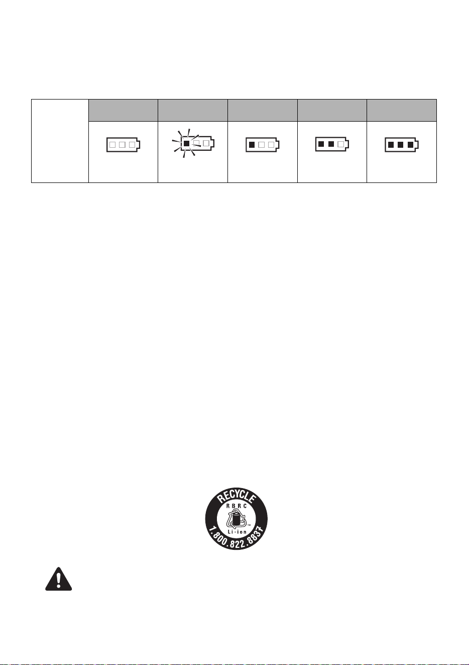
11. BATTERY INSTRUCTIONS
About the Battery Level Indicator
(1) To check the battery level (excluding while charging or while operating the charging
tool), press the Battery level check button (Fig.47.I).
(2) The Battery level gauge (Fig.47.J) is on according to the battery level.
Service Life of the Battery pack
If any condition described below is observed, the Battery pack is at the end of its service life. Replace it
with a new one.
Although the Battery pack has been properly charged (fully charged), a great drop in tying time has been
noticed.
• Do not charge the Battery pack when this happens. If the motor’s rotational speed slows down,
the power of the Battery pack is considered to be nearly depleted. Using the tool more will
cause it to overdischarge, resulting in a shortened service life of the Battery pack and also in
functional trouble of the tool’s main body.
• Do not use a Battery pack when its service life is finished.
• This will cause functional trouble in the tool’s main body. Also charging a Battery pack that is
out of service life will lead to functional trouble in the Charger.
• Do not dispose of battery packs/batteries into fire or water. Battery packs/batteries should be
collected, recycled or disposed of in an environmental-friendly manner.
• Protect the battery against heat, also against continuous sun irradiation and fire. There is
danger of explosion.
• Charge the battery pack in a temperature range 41°F (5°C) to 104°F (40°C).
Recycling a Li-ion Battery
The product you have purchased is powered by a Li-ion battery which is recyclable. At the end of its
useful life, under various state and local laws, it is illegal to dispose of this battery into your municipal
waste stream. Please call 1-800-8-BATTERY for information on how to recycle this battery.
The MAX battery pack uses a Li-ion battery, it may be illegal to dispose of this Battery into the municipal
waste system. Check with your local solid waste officials for details in your area for recycling options or
proper disposal.
When disposing of the Battery pack, make sure to put a Pack cap on its Terminal (with insulating
tape securing it) to prevent short circuits.
Battery level
gauge
Battery level:
0%
Battery level:
about 0 to 10%
Battery level:
about 10 to 40%
Battery level:
about 40 to 70%
Battery level:
about 70 to 100%
All indicators
OFF
One red
indicator blinks
One red
indicator ON
Two red
indicators ON
Three red
indicators ON
NOTICE
CAUTION

14
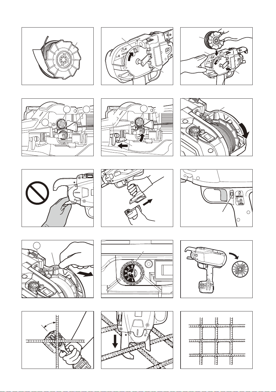
12. OPERATING INSTRUCTIONS
1. How to set the Tiewire
• Set the Main switch (Fig.6.7) at "OFF", the Trigger lock
(Fig.6.8) at "LOCK" and remove the Battery pack
(Fig.6.0), when changing the Battery pack, replacing or
adjusting the Tiewire, abnormalities occur, and the tool is
not being used
1-1 (Fig.9) Press the Release Lever (Fig.9.3) of this
equipment, and confirm that the Release Lever is caught in
the Release Stopper (Fig.9.2).
1-2 (Fig.10) Peel off the tape fixing Tiewire by about 5cm (2").
Stretch out the tip of the wound Tiewire.
Be sure to use only the specified Tiewire (MAX
TW898 Series).
The use of binding wire that has not been specified may cause
breakdown of this equipment. Therefore, be sure only to use the
specified MAX TW898. Do not use binding wire that has become
rusted, since the use of rusted wire will cause equipment
breakdown.
* TW897A, old wire reel cannot be used.
1-3 (Fig.11) Push the Reel stopper (Fig.11.d) to release the
Reel holder (Fig.11.f).
1-4 (Fig.12) Set the Tiewire (Fig.12.c) in the tool by matching
the side of the Tiewire as shown in the picture. Then push
the Reel holder (Fig.12.f) and fix it by sliding the Reel
stopper.
1-5 (Fig.13) Insert the tip of the stretched out Tiewire into the
Wire Guide (Fig,13.m). Then put it into the Pipe (Fig.13.n).
1-6 Put the Wire around 4" (10cm) inside the Pipe.
1-7 The tip of the Tiewire should be straightened out to allow it
to pass through the wire feeding mechanism. When
mounting the Tiewire, the wire may become jammed inside
the machine if the wire tip is bent.
(Fig.14) If the window is dirty and the pipe position
can not be confirmed
Open the window and wipe off the dirt on the inside of the window
with a soft cloth, etc. Close the window again after cleaning to
ensure that foreign objects will not be able to enter the machine.
1-8 (Fig.14) Release the Release stopper (Fig.14.2), and
confirm that the Release lever (Fig.14.3) has returned to
its original position and that the Feeding gears (Fig.14.l)
are clamping the Tiewire (Fig.14.c). This completes the
Tiewire mounting operation.
1-9 Remove the tape from the Tiewire completely.
1-10 (Fig.15) Remove slack from wire spool. Make sure the
Tiewire does not get caught behind the wire spool .This
could lead to jamming.
• (Fig.16) When setting the main switch to ON, absolutely
do not bring your hand close to the binding part or rotat-
ing part of the tip of the tool.
• Do not touch the Tiewire during the tying work (while the
machine is operating).
• Do not switch the main switch ON and OFF in rapid suc-
cession, since this operation will cause machine break-
downs.
1-11 (Fig.17) Mount the Battery pack on the tool's main body
until a click is heard. Turn the Main Switch ON.
1-12 (RB518, RB218) (Fig.37) Tool feeds the wire about 6"
(150 mm) and cuts the wire automatically.Remove the cut
end of the wire with pliers.
1-13 (Fig.18) Set the Trigger lock (Fig.18.8) to the position of
UNLOCK before using the tool.
2. How to remove the Tiewire
• (Fig.6) Set the Main switch (Fig.6.7) at "OFF", the Trigger
lock (Fig.6.8) at "LOCK" and remove the Battery pack
(Fig.6.0).
2-1 (Fig.9) Press the release lever (Fig.9.3), and confirm that
the release lever is caught in the release stopper(Fig.9.2).
2-2 (Fig.19) Remove the Tiewire (Fig.19.c) from the wire guide
(Fig.19.m).
2-3 (Fig.12) Slide the Reel stopper (Fig.12.d) to release the
Reel holder (Fig.12.f) and remove theTiewire (Fig.12.c)
2-4 Mount the new Tiewire. (Refer to the Tiewire mounting
method explanation.)
3. When the Tiewire runs out of binding wire
There should be around 12" (300 mm) of the Tiewire left at end
of the spool. This should be discharged with the old spool and be
replaced with a new one.
4. (RB398S) Tension adjustment
(Fig.20) This dial (Fig.20.5) allows you to adjust wire tension
torque slightly. To increase the tension, turn it in the
counterclockwise. To decrease the tension, turn it in the
clockwise.
4. (RB518) Tension and wrap adjustment
(Fig.38) Torque and wrap dial (fig.38.5) allows you to set 3
wraps / tie or 4 wraps / tie and also you can adjust the torque.
To increase the tension, turn it in the counterclockwise.
To decrease the tension, turn it in the clockwise.
4. (RB218) Wire length adjustment
(Fig.40) The Feed dial (Fig.39.5) is a mechanism to adjust feed
rate of the Tie-Wire. When the edge part (Fig.40.x) length is not
appropriate after binding, use this dial to adjust it.
5. Auto Power-off feature
This tool has "Auto Power-off" feature, which saves the power
consumption of the Li-ion battery when the tool is not operated. If
the tool is not operated for 30 minutes, the tool is automatically
turned off. This is "Auto Poweroff". When the power is turned off
automatically, turn the Main switch OFF, then turn ON the switch
again to operate the tool.
6. How to operate RB398S/RB518/RB218
Set the Main switch (Fig.6.7) at "OFF", the Trigger lock
(Fig.6.8) at "LOCK" and remove the Battery pack (Fig.6.0).
6-1 (Fig.17) Mount the Battery pack on the tool's main body until
a click is heard.
6-2 When Main switch (7) is turned "ON", the Hook of the tip
rotates automatically for initializing, absolutely do not bring
your fingers close to any rotating and moving part. Set the
Main switch at "ON" and the trigger lock (8) at "UNLOCK".
6-3 (Fig.22) Tilt the tool 45° angle to the crossed rebars.
6-4 (Fig.23) Apply the tool perpendicularly to the surface of the
crossed re-bars.
6-5 Once pull the Trigger, the tool automatically completes a
series of tying actions (feeding, cutting, gripping and tying).
WARNING
NOTICE
WARNING
NOTICE
15
During tool operation
• Do not move the tool during tying operation until the tool
stops tying automatically.
6-6 (Fig.24) Tie in alternate direction.
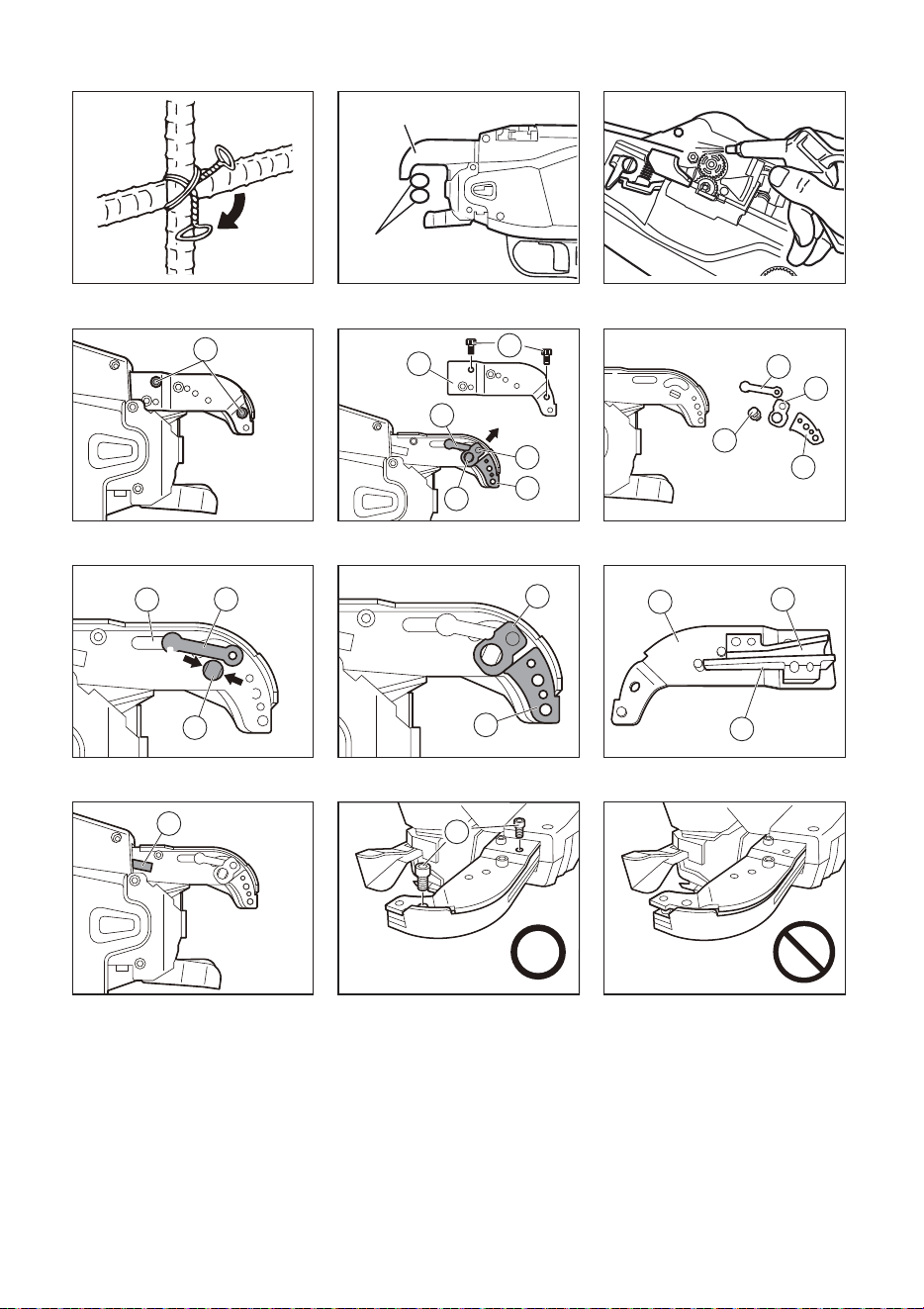
6-7 (Fig.25) Cross tie.
Bend the tail of the first tie before making the second tie.
6-8 (Fig.26) When you need extra tightness, place rebars
(Fig.26.a) at the top of the Arm part (Fig.26.1).
13. MAINTENANCE
1-1 Regularly inspect the tool
In order to maintain the performance of the tool, periodically
clean up and inspect the tool.
1-2 Do not lubricate the equipment
Absolutely do not lubricate this equipment. Applying
lubrication will remove the grease inside of the tool, and
cause problem on the tool.
1-3 (Fig.27) Regularly clean the feeding mechanism
In order to maintain the performance of the tool, periodically
clean up the mechanism around the feed gear. Using the Air
Duster or like, blow the dust and the iron sand off around the
feed gear.
1-4 Wipe the tool with a soft dry cloth.
Do not use a wet cloth or volatile substances such as
thinner or benzine.
14. CLEANING MANUAL
When the machine operates for long hours, dust and wire
cuttings may adhere to the cutter section. In such a case,
disassemble and clean the machine according to the following
procedure. (If a wire is caught in the cutter section or wire guide
A, the wire can be removed according to the same procedure.)
(RB398S)
Disassembling
• Do not remove the 2 uncoated bolts.
1-1 Loosen the 2 (plated) Hexagon socket head bolts M3 × 6
(Fig.28.o)
1-2 Remove Arm B (Fig.29.t) and the 2 (plated) Hexagon
socket head bolts M3 × 6 (Fig.29.o).
1-3 Remove the Cutter (Fig.30.p) and the Fixed cutter
(Fig.30.r), and clean them. (The removable parts are the
Cutter (Fig.30.p), Fixed cutter(Fig.30.r), Wire guide A
(Fig.30.q) and Cutter plate unit.(Fig.30.s).
Assembling
• (Fig.31) Assemble the Fixed cutter (Fig.31.r) so that the
Large hole (Fig.31.b) is set to the rear side and the Small
hole (long hole) (Fig.31.c) is set to the top side.
1-4 Put the pin of the cutter plate unit (Fig.31.s) through the
Cutter connecting rod hole (Fig.31.u) and assemble the
fixed cutter (Fig.31.r) to the unit.
1-5 Fit the Cutter (Fig.32.p) and assemble Wire guide A
(Fig.32.q).
1-6 Align the groove (Fig.33.v) of Wire guide B (Fig,33.w)
attached to Arm B (Fig.33.t) with the Pipe (Fig.34.n), and
assemble Arm B.
1-7 (Fig.35) Make sure that Arm B is securely assembled and
tighten the 2 (plated) Hexagon socket head bolts M3 × 6.
(Fig.35.o) (Tightening torque: 15.5 lbf·in (175 cN·m))
• (Fig.36) Are there any loosening parts?
Make sure that the outer parts are aligned and the parts are
securely assembled without any gap between them.
(RB518) (RB218)
Disassembling
1-1 (Fig.41) Loosen the 2 (plated) Hexagon socket head bolts
M3 × 5 (Fig.41.y).
1-2 (Fig.42) Remove Arm B (Fig.42.z) and the 2 (plated)
Hexagon socket head bolts M3 × 5 (Fig.42.y).
1-3 (Fig.43) Remove the Cutter (Fig.43.D) and the Fixed cutter
(Fig.43.C), and clean them. (The removable parts are the
Cutter, Fixed cutter and Step pin (Fig.43.B).)
Assembling
• (Fig.44) Assemble the Fixed cutter (Fig.44.C) so that the
Large hole (Fig.44.G) is set to the Rear side and the Small
hole (Fig.43.H) is set to the Top side.
1-4 (Fig.45) Insert the step pin (Fig.45.B) into the hole and then
into the Connecting rod (Fig.43.F) hole. Make sure the
Step pin is fully inserted.
1-5 (Fig.46) Make sure that Arm B (Fig.41.z) is securely
assembled and tighten the 2 (plated) Hexagon socket head
bolts M3 × 5 (Fig.46.y). (Tightening torque: 15.5 lbf·in
(175 cN·m))
• The (right) bolt (Fig.46.y) should have the Washer
(Fig.46.E). Install the washer first and then tighten the
bolt.
15. STORAGE
Do not store the tool in a cold weather environment. Keep the tool
in a warm area. When not in use, the tool should be stored in a
warm and dry place. Keep out of reach of children. All quality
tools will eventually require servicing or replacement of parts
because of wear from normal use.
(Fig.21) Remove reel of Tiewire
When you have finished the Tiewire, remove the Tiewire from the
tool.
Store the tool
When you have finished tying work or when the tool will not be
used for a while, switch off the tool, make sure the motor has
stopped, lock the trigger, and remove the battery pack. Tool,
attachments and accessories should be stored in a well-
ventilated dry place where the temperature will not exceed 104°F
(40°C). The battery pack, with a pack cap installed on the pack's
terminal to prevent short circuits, should be stored in a well-
ventilated dry place where the temperature will not exceed 86°F
(30°C).
NOTICE
NOTICE
Rear side Top side
NOTICE
NOTICE
Rear side Top side
NOTICE

16
16. TROUBLE SHOOTING/REPAIRS
The troubleshooting and/or repairs shall be carried out only by the MAX CO., LTD. authorized distributors or by other specialists.
This tool alerts you to the following conditions by means of a warning sound and warning lamp. The warning lamp is illuminated or blinks,
and is interlocked with the warning sound. Take a countermeasure according to the following table.
• If any of the following conditions occur, be sure to set the Main switch (Fig.1.7) to OFF before carrying out the countermeas-
ures.
• When setting the Main switch to ON, do not touch the tying part of rotating part of the tool's tip.
If the problem is not solved by carrying out the following countermeasures, be sure to set the Main switch to OFF and then
contact the dealer where the equipment was purchased or MAX CO., LTD. authorized distributors.
No. Normal Operation Problem
Warning
Sound
Cause What to Check Solution
1. Power ON → The
Tip Axis is initialized
and the wire-cutter
operates automati-
cally.
No operation
takes place.
No sound
emitted.
Dead battery (Com-
pletely empty)
Confirm the battery is
charged.
Perform normal charge.
Electrode plate has
been oxidized.
Taking out the battery,
see if electrode has been
browned.
Polish terminal part of
battery pack with dry
cloth, etc.
A long beep
(Piii...)
Curl guide (Fig.1.b)
is left open.
Open/close curl guide Fully close curl guide.
Continuous
short beeps
(Pi, pi, pi, ...)
Binding wire has
been entangled
around Twist sec-
tion.
Turn off power and take
out battery to confirm if
binding wire has been
entangled inside curl
guide.
Turning off power, re-
move binding wire inside
curl guide.
Two short
beeps repeat-
ed for 10 sec-
onds (Pipi,
Pipi, ...), then
power off au-
tomatically
Battery is empty. Confirm the battery is
charged.
Perform normal charge.
The Battery pack is
inserted when the
Main switch is ON.
Make sure to insert the
Battery pack, only when
the Main switch is OFF.
Set the Main switch to
OFF, then ON.
2. Power On → LED
lamp is lit. → No op-
eration over 30 min-
utes → LED lamp
goes off. → Al-
though pulling the
trigger, no opera-
tion takes place.
No operation
takes place, al-
though pulling
the trigger
No sound
emitted
Normal operation. Set the Main switch to
OFF, then ON.
Set the Main switch to
OFF, then ON.
3. Trigger ON → Wire
sent out.
No sending of
wire takes place.
A long beep
(Piii...)
Curl guide is left
open.
Open/close curl guide Fully close curl guide.
Three short
beeps repeat-
ed
(Pipipi,
pipipi, ...)
Tiewire has been run
out.
Check if the Tiewire has
been run out or not.
Set the new Tiewire.
Wire caught inside
reel.
Check if wire inside reel
has been loosened and
caught.
Remove fray on reel.
Cutter section
(Fig.29) is blocked
with foreign sub-
stance.
Confirm functioning of
Cutter section.
Either wipe Cutter sec-
tion with dry cloth or blow
it with air.
A wire is caught in
the cutter section or
wire guide A
(Fig.29.q).
Check if any wire is
caught.
Disassemble the cutter
section and remove the
caught wire. (Fig.28~36)
Five short
beeps
(Pipipipipi,
pipipipipi)
Motor has been
heated.
Warning sound does not
go continuously. It occurs
only when trigger is
pulled.
Halt Machine and cool it
down.
3. Trigger ON → Wire
sent out.
Sending of wire
is stopped half-
way.
Four short
beeps repeat-
ed
(Pipipipi,
pipipipi, ...)
Tiewire is not set in
the tool.
Check if the Tiewire has
been set in the tool.
Set the Tiewire.
Binding wire not of
designated types
has been used.
Confirm reel side face. Use MAX Tiewire
TW898.
Three short
beeps repeat-
ed
(Pipipi,
pipipi, ...)
Binding wire has
been entangled in-
side reel.
Confirm reel winding Remove fray on reel.
4. Binding wire draws
a circle.
Curl is disor-
dered and steps
out of curl guide.
No sound
emitted.
Wire, by hitting Rein-
forcing bars, was re-
pelled.
Check if wire hits Rein-
forcing bars at binding.
Pay attention so that
wire does not hit Rein-
forcing bars at binding.
5. Wire is subject to
cutting.
No wire cutting
takes place.
Continuous
short beeps.
(Pipipipipipi...)
Cutter section is
blocked with foreign
substance.
Confirm function of Cut-
ter section.
Either wipe Cutter sec-
tion with dry cloth or blow
it with air.
WARNING

17
6. Wire twisting takes
place.
Wire gets entan-
gled.
No sound
emitted.
Wire, by hitting Rein-
forcing bars, was re-
pelted.
Check if wire hits Rein-
forcing bars at binding.
Pay attention so that
wire does not hit Rein-
forcing bars at binding.
A short beep
and a long
beep, repeat-
edly.
(Pipipipipipi...)
Binding wire has
been entangled
around Twist sec-
tion.
Turn off power and take
out battery to confirm if
binding wire has been
entangled inside curl
guide.
Turning off power, re-
move binding wire inside
curl guide.
Binding power is
weak.
No sound
emitted.
Reinforcing bars is
not of designated
size.
Confirm size of Reinforc-
ing bars to be bound.
(SEE PAGE 12)
Use appropriate diame-
ter scope.
Erroneous handling
such as improper ap-
plication of Machine.
Confirm how to apply Ma-
chine to Reinforcing bars.
Turning Torque dial
(Fig.1.5) in + and insert-
ing in vertical direction,
use as tilting at 45°.
(Fig.22)
Function of curl
guide switch
Check if curl guide is left
open at binding.
Do not operate Machine
until binding is complet-
ed.
Twisting-off
takes place.
No sound
emitted.
Reinforcing bars is
not of designated
size.
Confirm size of Reinforc-
ing bars at binding.
(SEE PAGE 12)
Use appropriate diame-
ter scope.
Erroneous handling
such as improper ap-
plication of Machine.
Confirm how to apply Ma-
chine to Reinforcing bars.
Turning Torque dial in –
(minus) and inserting in
vertical direction, use as
tilting at 45°. (Fig.22)
Works properly Two short
beeps.
(Pipi)
Low power remains
in the Battery pack.
Confirm the battery is ful-
ly charged.
Perform normal charge
after the tying speed
slows down considera-
bly.
The tool is used at
low temperature.
Check the temperature at
the job site.
Leave the tool and the
Battery pack at normal
temperature in the room
for some time, and then
continue the operation.
No. Normal Operation Problem
Warning
Sound
Cause What to Check Solution

18
SOMMAIRE
1. NOM DES PIÈCES .......................................................................................................................................... 18
2. LISTE DU CONTENU ...................................................................................................................................... 19
3. AVERTISSEMENTS DE SÉCURITÉ GÉNÉRAUX RELATIFS AUX OUTILS ÉLECTRIQUES...................... 19
4. DISPOSITIFS DE SÉCURITÉ RB398S/RB518/RB218................................................................................... 21
5. CARACTÉRISTIQUES TECHNIQUES ET DONNÉES TECHNIQUES DE L'OUTIL...................................... 23
6. CARACTÉRISTIQUES TECHNIQUES............................................................................................................ 24
7. ANNÉE DE PRODUCTION ............................................................................................................................. 24
8. SPÉCIFICATIONS DU FIL .............................................................................................................................. 25
9. APPLICATIONS .............................................................................................................................................. 25
10. TAILLES DE BARRES UTILISABLES ........................................................................................................... 25
11. INSTRUCTIONS CONCERNANT LA BATTERIE........................................................................................... 26
12. UTILISATION................................................................................................................................................... 27
13. MAINTENANCE............................................................................................................................................... 28
14. MANUEL DE NETTOYAGE ............................................................................................................................ 28
15. ENTREPOSAGE.............................................................................................................................................. 28
16. DÉPANNAGE/RÉPARATION ......................................................................................................................... 29
DÉFINITION DES MOTS-INDICATEURS
AVERTISSEMENT : indique une situation dangereuse qui, si elle n'est pas évitée, pourrait entraîner la mort ou
des blessures graves.
ATTENTION : indique une situation dangereuse qui, si elle n'est pas évitée, pourrait des blessures
graves mineures ou modérées.
AVIS : indique un message relatif à des dommages matériels.
1. NOM DES PIÈCES
Fig. 1
Fig. 2 Bloc batterie
Fig. 3 Chargeur de batterie
Reportez-vous au manuel d'utilisation et d'entretien du JC925A.
Fig. 13 à 47
FRANÇAIS
MODE D'EMPLOI ET CONSIGNES DE SÉCURITÉ
1 Bras
2 Pièce de retenue de déclenchement
3 Levier de déclenchement
4 Fenêtre
5 Molette à couple (RB398S)
Molette de couple et des spires (RB518)
Molette d'alimentation (RB218)
6 Voyant LED
7 Interrupteur principal
8 Verrouillage du déclencheur
9 Poignée
0 Bloc batterie
a Déclencheur
b Guide de bouclage
c Fil à ligature
d Pièce de retenue de la bobine
e Année et numéro de production
f Support de la bobine
g Crochet de ceinture
h Verrou
i Couvercle de batterie
j Borne
l Engrenage d'alimentation
m Guide de fil
n Tuyau
o Écrou à tête à six pans creux M3 × 6
p Couteau
q Guide-fil A
r Couteau fixe
s Unité de plaque du couteau
t Bras B
u Orifice de la bielle de connexion du couteau
v rainure
Traduction des
instructions originales
19
Symboles
Les symboles suivants sont utilisés pour la machine.
2. LISTE DU CONTENU
• OUTIL DE LIGATURE DE BARRES MAX/
RB398S/RB518/RB218
• Bloc batterie lithium-ion/JPL91450A
• Chargeur de batterie lithium-ion/JC925A
• Cordon d'alimentation
• Crochet de ceinture
• MODE D'EMPLOI ET CONSIGNES DE
SÉCURITÉ (le présent manuel)
3. AVERTISSEMENTS DE SÉCURITÉ
GÉNÉRAUX RELATIFS AUX OUTILS
ÉLECTRIQUES
1. Sécurité de la zone de travail
• Maintenez la zone de travail propre et bien éclairée.
Des zones en désordre ou sombres entraînent des
accidents.
• N'utilisez pas les outils électriques dans des
atmosphères explosives, telles qu'en présence de
liquides, gaz ou poussière inflammables. Les outils
électriques créent des étincelles qui enflamment la
poussière ou les vapeurs.
• Tenez les enfants ou les personnes qui vous
entourent à distance lorsque vous utilisez un outil
électrique. Des distractions peuvent vous faire perdre le
contrôle de l'outil.
2. Sécurité électrique
• Les fiches des outils électriques doivent s'adapter à
la prise. Ne modifiez jamais en aucune manière la
fiche d'un outil. N'utilisez aucune fiche d'adaptateur
avec des outils électriques mis à la terre (masse). Des
fiches non modifiées et des prises adaptées réduiront le
risque de choc électrique.
• Évitez tout contact corporel avec les surfaces mises à
la terre ou à la masse, telles que des tuyaux, des
radiateurs, des cuisinières et des réfrigérateurs. Le
risque de choc électrique est accru si votre corps est mis
à la terre ou à la masse.
• N'exposez pas les outils électriques à la pluie ou
l'humidité. La pénétration d'eau dans un outil électrique
augmente le risque de choc électrique.
• Ne détériorez pas le cordon. N'utilisez jamais le
cordon pour porter, tirer ou débrancher l'outil
électrique. Maintenez le cordon à distance de la
chaleur, de l'huile, de bords tranchants et de pièces
mobiles. Des cordons endommagés ou emmêlés
augmentent le risque de choc électrique.
•
Lorsque vous utilisez un outil électrique à l'extérieur,
utilisez une rallonge adaptée.
L'utilisation d'une rallonge
adaptée à une utilisation à l'extérieur réduit le risque de
choc électrique.
• Si vous êtes obligé d'utiliser un outil électrique dans
un endroit humide, utilisez une alimentation
électrique protégée par un disjoncteur différentiel de
fuite à la terre (DDFT). L'utilisation d'un DDFT réduit le
risque de choc électrique.
3. Sécurité personnelle
•
Restez vigilant, regardez ce que vous faites et faites
preuve de bon sens lorsque vous utilisez un outil
électrique. N'utilisez pas un outil électrique lorsque vous
êtes fatigué ou sous l'influence de drogues, d'alcool ou
de médicaments.
Un moment d'inattention lorsque vous
utilisez des outils électriques peut entraîner des blessures
graves.
w Guide-fil B
x bord
z Écrou à tête à six pans creux M3 × 6
z Bras B
A Guide-fil A
B Boulon à gradins
C Couteau fixe
D Couteau
E Rondelle
F Bielle de connexion
G Grand orifice
H Petit orifice
I Bouton de vérification du niveau de batterie
J Jauge du niveau de batterie
Tenez les mains et les parties du corps
éloignées du bras et du guide de
bouclage.
DÉVERROUILLER
VERROUILLER
Volts nominaux
Courant continu
ATTENTION
AVERTISSEMENT
Lisez le mode d’emploi et les consignes
de sécurité avant d’utiliser l’outil.
Portez des lunettes de sécurité.
N’exposez pas à la pluie.
Ne jetez pas les blocs batteries/batteries
au feu ou dans l’eau.
Protégez la batterie contre la chaleur et
l’exposition au soleil.
Lisez tous les avertissements de sécurité, toutes les
consignes, toutes les illustrations et toutes les
spécifications fournis avec cet outil électrique. Un non-
respect de chacune des consignes listées ci-dessous peut
entraîner un choc électrique, un incendie et/ou des blessures
graves.
Conservez tous les avertissements et consignes pour
une consultation ultérieure.
Le terme « outil électrique » dans les avertissements fait
référence à votre outil électrique raccordé au secteur (cordon
d'alimentation) ou fonctionnant avec une batterie (sans fil).
AVERTISSEMENT

20
• Utilisez un équipement de protection individuel.
Portez toujours une protection oculaire. Un
équipement de protection tel qu'un masque antipoussière,
des chaussures de sécurité antidérapantes, un casque ou
une protection auditive, utilisé dans des conditions
appropriées réduira les dommages corporels.
• Évitez tout démarrage involontaire. Vérifiez que
l'interrupteur est en position Arrêt avant de brancher
la source électrique et/ou le bloc batterie, de ramasser
ou de transporter l'outil. Le transport d'outils électriques
avec le doigt sur l'interrupteur ou la mise sous tension
d'outils électriques dont l'interrupteur est en position
Marche entraîne des risques d'accident.
• Retirez toute clé ou clavette de calage avant de mettre
l'appareil électrique sous tension. Une clé ou une
clavette toujours fixée sur une pièce rotative de l'outil
électrique peut entraîner des dommages corporels.
• Portez une tenue appropriée. Ne portez pas de
vêtements amples ni de bijoux. Tenez vos cheveux et
vêtements à distance des pièces mobiles. Des
vêtements amples, des bijoux ou des cheveux longs
peuvent se coincer dans les pièces mobiles.
• Portez une tenue appropriée. Ne portez pas de
vêtements amples ni de bijoux. Tenez vos cheveux,
vêtements et gants à distance des pièces mobiles.
Des vêtements amples, des bijoux ou des cheveux longs
peuvent se coincer dans les pièces mobiles.
• Si des appareils sont fournis pour le raccordement
aux dispositifs de récupération et d'extraction de la
poussière, vérifiez qu'ils sont raccordés et
correctement utilisés. L'utilisation d'un dispositif de
récupération de la poussière peut réduire les risques liés
à la poussière.
• La connaissance des outils, acquise par l'usage
fréquent de ces derniers, ne doit pas vous dispenser
d'être prudent et d'appliquer les principes de sécurité.
Une action inconsidérée peut provoquer de graves
blessures en une fraction de seconde.
4. Utilisation et entretien d'un outil électrique
• N'exercez aucune force sur l'outil. Utilisez l'outil
électrique adapté à votre application. L'outil électrique
adapté exécutera le travail d'une manière plus correcte et
plus sûre à la vitesse pour laquelle il est conçu.
• N'utilisez pas l'outil électrique si l'interrupteur ne
fonctionne pas correctement. Un outil électrique qui ne
peut pas être commandé à l'aide de l'interrupteur est
dangereux et doit être réparé.
• Débranchez la fiche de l’alimentation électrique et/ou
retirez le bloc-batterie, s’il est amovible, de l’outil
électrique, avant d’effectuer un quelconque réglage,
de changer d’accessoire ou de ranger l’outil
électrique. Ces mesures préventives réduisent le risque
d'un démarrage accidentel de l'outil électrique.
• Rangez des outils électriques à l'arrêt hors de portée
des enfants et ne laissez pas des personnes non
familiarisées avec l'outil électrique ou ces consignes
utiliser cet outil. Les outils électriques sont dangereux
dans les mains d'utilisateurs non formés.
• Entretenez les outils électriques et les accessoires.
Vérifiez que des pièces mobiles ne sont pas
désalignées ou coincées, que des pièces ne sont pas
cassées ou vérifiez tout autre état qui pourrait gêner
le fonctionnement de l'outil électrique. Si l'outil
électrique est endommagé, faites-le réparer. Un grand
nombre d'accidents sont causés par des outils électriques
mal entretenus.
• Maintenez les outils de coupe affûtés et propres. Des
outils de coupe correctement entretenus avec des bords
tranchants affûtés risquent moins de se coincer et sont
plus faciles à contrôler.
• Utilisez l'outil électrique, les accessoires et les
embouts, etc. conformément à ces consignes, en
prenant en compte les conditions de travail et le
travail à réaliser. L'utilisation de l'outil électrique pour des
opérations différentes de celles pour lesquelles il est
prévu peut entraîner une situation dangereuse.
• Les poignées et les surfaces de maintien doivent
toujours être propres, sèches et sans traces d’huile ni
de graisse. Les poignées et surfaces de maintien
glissantes empêchent de manipuler et de contrôler l’outil
en toute sécurité dans des situations imprévues.
5. Utilisation et entretien d'un outil fonctionnant avec
une batterie
• Rechargez uniquement à l'aide du chargeur spécifié
par le fabricant. Un chargeur adapté à un type de bloc
batterie peut entraîner un risque d'incendie lorsqu'il est
utilisé avec un autre bloc batterie.
• Utilisez les outils électriques uniquement avec les
blocs batteries spécifiés. L'utilisation d'autres blocs
batteries peut entraîner un risque de blessure et
d'incendie.
• Lorsque le bloc batterie n'est pas utilisé, tenez-le à
distance d'autres objets métalliques, tels que des
trombones, pièces, clés, clous, vis ou autres petits
objets métalliques, qui peuvent créer un contact entre
les deux bornes. Un court-circuit des bornes de la
batterie peut entraîner des brûlures ou un incendie.
• En cas d'utilisation incorrecte, du liquide peut être
éjecté de la batterie ; évitez tout contact avec ce
liquide. En cas de contact accidentel, rincez avec de
l'eau. Si du liquide entre en contact avec les yeux,
consultez immédiatement un médecin. Le liquide
éjecté de la batterie peut entraîner une irritation ou des
brûlures.
• N’utilisez pas un bloc batterie ou un outil endommagé
ou modifié. Les batteries endommagées ou modifiées
peuvent présenter un comportement imprévisible
susceptible de provoquer un incendie, une explosion ou
un risque de blessure.
• N’exposez pas un bloc batterie ou un outil au feu ou à
des températures trop élevées. L’exposition au feu ou à
des températures supérieures à 130 °C peut provoquer
une explosion.
• Respectez toutes les instructions de charge et ne
chargez pas le bloc batterie ou l’outil en dehors de la
plage de température spécifiée dans les instructions.
Ne pas charger la batterie correctement ou la charger à
des températures hors de la plage spécifiée peut
endommager la batterie et augmenter le risque
d’incendie.
6. Service
• Faites réparer votre outil électrique par un réparateur
qualifié qui n'utilise que des pièces de rechange
d'origine. Ceci garantit le maintien de la sécurité de l'outil
électrique.
• N’entretenez jamais des blocs batteries
endommagés. L’entretien des blocs batteries doit être
effectué uniquement par le fabricant ou par les
fournisseurs de services autorisés.

21
4. DISPOSITIFS DE SÉCURITÉ
RB398S/RB518/RB218
1. INSPECTEZ LES PIÈCES AVANT LA MISE EN
PLACE DU BLOC BATTERIE
• Examinez les vis, afin de vérifier leur serrage.
En cas de mauvais serrage, vous risquez un accident ou
une cassure. Si vous constatez une vis desserrée,
resserrez-la complètement.
• Examinez l'outil, à la recherche de pièces détériorées.
Les pièces s'usent au fil de l'utilisation. Recherchez
également des pièces manquantes, défectueuses ou
dégradées. Si vous devez remplacer ou réparer une
pièce, procurez-vous la pièce de rechange chez le
distributeur vous avez acheté l'outil ou auprès de
distributeurs agréés MAX CO., LTD.
Utilisez uniquement des pièces de rechange d'origine.
2. RÉGLEZ L'INTERRUPTEUR PRINCIPAL (Fig. 6.7)
SUR « OFF », LE VERROUILLAGE DU
DÉCLENCHEUR (Fig. 6.8) SUR « LOCK » ET ÔTEZ
LE BLOC BATTERIE (Fig. 6.0), LORSQUE VOUS
CHANGEZ LE BLOC BATTERIE, QUE VOUS
REMPLACEZ OU RÉGLEZ LE FIL À LIGATURE, EN
CAS D'ANOMALIE OU LORSQUE VOUS N'UTILISEZ
PAS L'OUTIL
Si vous laissez l'outil sous tension dans ces conditions, vous
risquez de provoquer une panne ou de l'endommager.
3. GARDEZ EN PERMANENCE LES DOIGTS ET
AUTRES PARTIES DU CORPS ÉLOIGNÉS DE LA
PARTIE ENTRE LE BRAS ET DU GUIDE DE
BOUCLAGE (Fig. 16)
Tout manquement à cette consigne peut entraîner des
blessures graves.
4. GARDEZ LES DOIGTS ET AUTRES PARTIES DU
CORPS ÉLOIGNÉS DU FIL À LIGATURE PENDANT
L'UTILISATION
Tout manquement à cette consigne peut entraîner des
blessures graves.
5. NE DIRIGEZ PAS L'OUTIL VERS UNE PERSONNE
Vous risquez de blesser une personne travaillant à
proximité, si l'outil la touche. Au cours de l'utilisation, soyez
très attentif à ne pas approcher les mains, les jambes ou
toute autre partie du corps, du bras de l'outil.
6. NE PAS GARDER LE DOIGT SUR LE
DÉCLENCHEUR EN DEHORS DE L'UTILISATION
Tout manquement à cette consigne peut provoquer une
ligature accidentelle, entraînant des blessures graves.
7. NE PAS UTILISER L'OUTIL DANS DES CONDITIONS
ANORMALES
Si l'outil n'est pas en état correct de fonctionnement, ou si
vous remarquez une condition anormale, mettez-le
immédiatement hors tension (interrupteur principal sur OFF),
verrouillez le déclencheur et faites-le examiner pour
réparation.
8. UNE FOIS LA BATTERIE EN PLACE, SI L'OUTIL SE
MET EN MARCHE SANS APPUYER SUR LE
DÉCLENCHEUR OU SI L'OPÉRATEUR REMARQUE
UN ÉCHAUFFEMENT, UNE ODEUR OU UN BRUIT
INHABITUEL, ARRÊTEZ-LE
Tout manquement à cette consigne peut entraîner des
blessures graves. Renvoyez l'outil au distributeur pour une
inspection de sécurité.
9. NE PAS MODIFIER L'OUTIL
Toute modification de l'outil a une incidence sur ses
performances et sa sécurité. D'autre part, toute modification
peut provoquer des blessures graves et annule la garantie.
10. MANIPULEZ L'OUTIL AVEC PRÉCAUTION
Le laisser tomber ou le soumettre à un choc peut entraîner
des pannes ou des dommages.
11. MAINTENIR L'OUTIL EN BON ÉTAT DE
FONCTIONNEMENT
Pour préserver le fonctionnement optimal et la sécurité de
l'outil, faites-le réparer en cas d'usure ou de détérioration.
Maintenez la poignée sèche et propre, exempte tout
particulièrement d'huile et de graisse.
12. UTILISER UNIQUEMENT LE BLOC BATTERIE
RECOMMANDÉ
Si l'outil est branché sur une alimentation autre que le bloc
batterie recommandé, telle qu'une batterie rechargeable,
une batterie à anode sèche ou une batterie d'accumulateurs
utilisée dans l'industrie automobile, il risque d'être
endommagé, de tomber en panne, de chauffer, voire même
de prendre feu. Ne branchez en aucun cas l'outil sur une
alimentation autre que le bloc batterie recommandé.
13. POUR UN MEILLEUR FONCTIONNEMENT,
CHARGER COMPLÈTEMENT LA BATTERIE AVANT
UTILISATION
Un nouveau bloc batterie, ou un non utilisé pendant une
période prolongée, peut être partiellement déchargé et
nécessiter une charge. Avant d'utiliser l'outil, rechargez le
bloc batterie à l'aide du chargeur MAX indiqué.
14. PRÉCAUTION POUR LA CHARGE DE LA BATTERIE
14-1 Utilisez uniquement le chargeur MAX avec
le bloc batterie MAX.
Tout manquement à cette consigne peut provoquer
une surchauffe/un incendie de la batterie, entraînant
de graves blessures.
14-2 Chargez la batterie à partir d'une prise
secteur de 100-240 V CA.
Tout manquement à cette consigne peut provoquer
une surchauffe, ou une charge incorrecte susceptible
d'entraîner des blessures graves.
14-3 N'utilisez jamais de transformateur.
14-4 Ne branchez pas le chargeur sur un
alternateur de moteur produisant du
courant continu.
Le chargeur tomberait en panne ou serait
endommagé par la surchauffe.
14-5 Évitez de charger la batterie sous la pluie,
dans un endroit humide, ou soumis à des
éclaboussures d'eau.
Le fait de charger la batterie dans ces conditions
risquerait de provoquer un choc électrique ou un
court-circuit entraînant une détérioration liée à la
surchauffe, avec risque d'incendie de l'outil.
14-6 Ne touchez pas le cordon d'alimentation
avec la main ou un gant mouillé.
Vous risqueriez un choc électrique.
14-7 Ne placez pas de chiffon ni autre
obstruction sur le chargeur pendant la
charge de la batterie.
Cela provoquerait une surchauffe et une détérioration
consécutive, voire même l'incendie de l'outil.
14-8 Conservez le bloc batterie et le chargeur à
l'abri des flammes et de la chaleur.
14-9 Ne chargez pas le bloc batterie à proximité
de matières inflammables.
14-10 Chargez le bloc batterie dans un endroit
bien aéré.
Évitez de charger le bloc batterie sous les rayons
directs du soleil.
14-11 Chargez le bloc batterie sous une
température ambiante comprise entre 41 °F
(5 °C) et 104 °F (40 °C).

22
14-12 Évitez d'utiliser le chargeur de batterie de
façon continue.
Laisser reposer le chargeur 15 minutes entre deux
utilisations pour éviter tout problème de
fonctionnement.
14-13 Tout objet obstruant les orifices de
ventilation ou le connecteur du bloc
batterie risque de provoquer un choc
électrique ou des anomalies de
fonctionnement.
Éliminez toute poussière ou objet étranger du
chargeur avant son utilisation.
14-14 Manipulez le cordon d'alimentation avec
soin.
Ne transportez pas le chargeur par son cordon
d'alimentation. N'utilisez pas le cordon d'alimentation
pour le débrancher de la prise murale ; vous risquez
de l'endommager, de rompre les fils ou de provoquer
un court-circuit. Ne laissez pas le cordon
d'alimentation entrer en contact avec des outils à bord
tranchant, des matériaux chauds ou de la graisse. Un
cordon d'alimentation endommagé doit être réparé ou
remplacé.
14-15 Ne chargez pas des batteries non
rechargeables au moyen de ce chargeur.
14-16 Ce chargeur ne doit pas être utilisé par des
enfants ou des personnes handicapées
sans la surveillance d'un responsable.
14-17 Les enfants doivent être surveillés afin de
s'assurer qu'ils ne jouent pas avec le
chargeur.
14-18 Placez le couvercle (Fig. 2.i) sur les
contacts (Fig. 2.j) du bloc batterie.
Lorsque la batterie n'est pas utilisée, placez le
couvercle sur ses contacts de façon à empêcher tout
court-circuit.
14-19 Ne laissez pas les contacts (métalliques)
de la batterie entrer en court-circuit.
Un court-circuit des contacts entraînerait un fort
courant provoquant un échauffement et une
détérioration de la batterie.
14-20 Pendant l'été, ne laissez pas l'outil dans un
véhicule ou exposé aux rayons directs du
soleil. La forte température risquerait
d'endommager le bloc batterie.
14-21 Ne stockez pas un bloc batterie
complètement déchargé. Un bloc batterie
retiré de l'outil pendant une longue période
risque de se détériorer s'il est
complètement déchargé. Rechargez-le dès
qu'il est déchargé.
15. PORT DE GANTS DE PROTECTION CONSEILLÉ
PENDANT L'UTILISATION
La ligature a des bords coupants. Pour éviter les blessures
graves, ne touchez pas les bords coupants. Max
recommande le port de gants de protection pendant
l'utilisation de l'outil.
16. AVANT TOUTE UTILISATION
(Fig. 4 et 5) Vérifiez que les dispositifs de sécurité
fonctionnent correctement. Dans le cas contraire, évitez
d'utiliser l'outil.

23
5. CARACTÉRISTIQUES TECHNIQUES ET DONNÉES TECHNIQUES DE L'OUTIL
<CHARGEUR DE BATTERIE>
<BLOC BATTERIE>
N'utilisez pas l'outil électrique sous la pluie, près de projections d'eau, dans un endroit mouillé ou humide. L'utilisation de l'outil
dans ces conditions ou des conditions similaires augmente le risque de choc électrique, de dysfonctionnement dangereux et de surchauffe.
DESCRIPTION DU PRODUIT Outil de ligature de barres MAX
NUMÉRO DU PRODUIT RB398S RB518 RB218
DIMENSIONS (batterie comprise) (H) 12'' (305 mm)
(l) 4-3/4'' (120 mm)
(L) 11-3/8'' (290 mm)
(H) 12" (305 mm)
(l) 4-1/8'' (105 mm)
(L) 12" (305 mm)
(H) 12" (305 mm)
(l) 4-1/8" (105 mm)
(L) 10-5/8" (270 mm)
POIDS (batterie comprise) 5 lbs / 2,3 kg 5,3 lbs / 2,4 kg
BATTERIE Li-ion 14,4 V/(JPL91450A)
TEMPÉRATURE DE FONCTIONNEMENT 14 °F to 104 °F / -10 °C to 40 °C
HUMIDITÉ 80 % d'humidité relative au maximum
DESCRIPTION DU PRODUIT Chargeur de batterie lithium-ion
MODÈLE JC925A
ENTRÉE 100 - 240 V CA 50/60 Hz 2,2 A
SORTIE 14,4 V CC 4 A, 18 V CC 4 A, 25,2 V CC 2,8 A
POIDS 1,6 lbs / 0,7 kg
PLAGE DE TEMPÉRATURES DE
FONCTIONNEMENT
41°F to 104°F (5°C to 40°C)
PLAGE D'HUMIDITÉ DE FONCTIONNEMENT 80 % d'humidité relative au maximum
DESCRIPTION DU PRODUIT Bloc batterie lithium-ion
MODÈLE JPL91450A
TENSION NOMINALE 14,4 V CC (3,6 V x 4 cellules)
CAPACITÉ NOMINALE 4,9 Ah (4 900 mAh)
TEMPS DE CHARGE Env. 60 min.(Env. 80 % de la capacité)
Env. 80 min.(100 % de la capacité)
ACCESSOIRES Couvercle de batterie (pour éviter les courts-circuits)
POIDS 1,1 lbs / 0,5 kg
TEMPÉRATURE DE CHARGE 41 °F to 104 °F (5 °C to 40 °C)
PLAGE DE TEMPÉRATURES DE
FONCTIONNEMENT
32 °F to 104 °F (0 °C to 40 °C)
PLAGE D'HUMIDITÉ DE FONCTIONNEMENT 80 % d'humidité relative au maximum
Ligatures par charge
(*dans les conditions suivantes : température
normale, batterie non utilisée, complètement
chargée)
RB398S RB518 RB218
Env. 4 000 ligatures
(3 spires/ligatures) Env.
3 200 ligatures
(4 spires/ligatures) Env.
2 900 ligatures
Env. 4 600 ligatures
24
6. CARACTÉRISTIQUES TECHNIQUES
1BRUIT
Valeur mesurée conformément à la norme EN 62841-1 :
Niveau de pression acoustique pondérée A (L
pA
): 82dB
Incertitude (K
pA
): 6dB
Niveau de puissance acoustique pondérée A (L
WA
): 93dB
Incertitude (K
WA
): 6dB
2VIBRATIONS
Valeur mesurée conformément à la norme EN 62841-1 :
Valeurs totales des vibrations (a
h
): 3,1m/s
2
Incertitude (K) : 1,5 m/s
2
Les informations suivantes :
• La valeur totale déclarée d'émission des vibrations a été mesurée conformément à une méthode standard de test et elle peut être
utilisée pour comparer un outil à un autre.
• La valeur totale déclarée d'émission des vibrations peut également être utilisée dans le cadre d'une évaluation préliminaire de
l'exposition.
• Les vibrations et les émissions sonores lors de l'utilisation réelle de l'outil électrique peuvent différer des valeurs d'émission
déclarées en fonction de la manière dont l'outil est utilisé, en particulier du type de pièce à traiter.
• Veillez à identifier les mesures de sécurité visant à protéger l'utilisateur et basées sur une estimation de l'exposition dans les
conditions réelles d'utilisation (en prenant en compte toutes les parties du cycle d'utilisation, notamment le nombre de fois où l'outil
est mis hors tension et lorsqu'il fonctionne au ralenti en plus de la durée d'utilisation du déclencheur).
3 ÉMISSION DE RAYONNEMENTS 30 - 1 000 MHz Classe A
Ceci est un produit de classe A. Dans un environnement domestique, ce produit peut provoquer des interférences
radio, auquel cas l'utilisateur peut être tenu de prendre les mesures appropriées.
4 Catégorie de surtension - Catégorie 1 en conformité avec la norme CEI 60664-1
5 Degré de pollution - Catégorie 4 en conformité avec la norme CEI 60664-1
6 Directives de conception – Directives de l'équipement, annexe 1, EN 62841-1
7. ANNÉE DE PRODUCTION
Ce produit comporte le numéro de fabrication sur le corps. Les deux chiffres les plus à gauche du numéro indiquent
l’année de production. Le chiffre suivant indique le mois.
AVERTISSEMENT
AVERTISSEMENT
(Exemple)
1 9 5 2 6 0 3 5 D
Année 2019
Exemple de notation du mois :
1 --- Janvier
2 --- Février
•
•
•
A --- Octobre
B --- Novembre
C --- Décembre
Mai
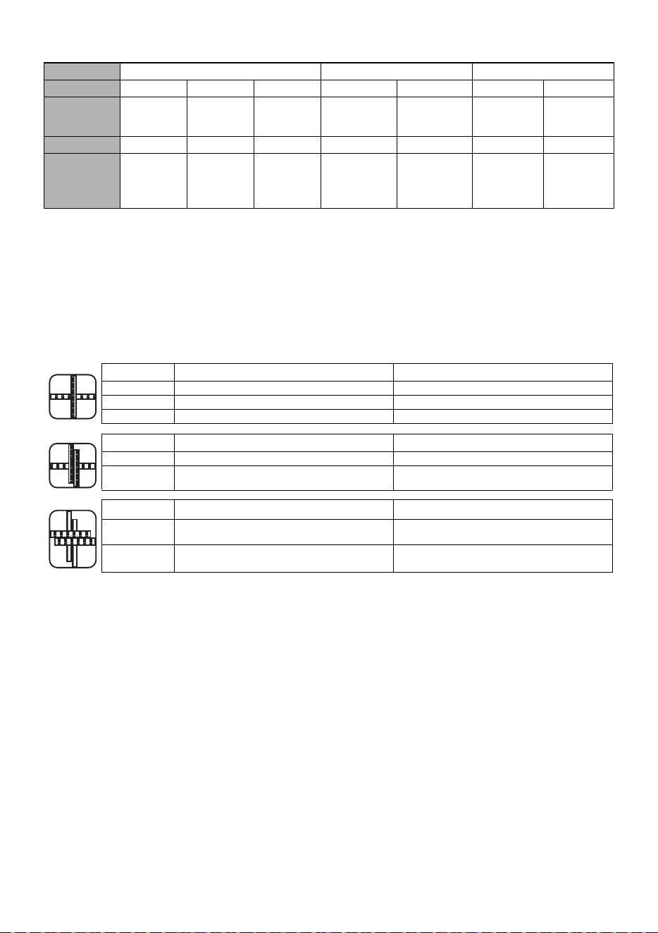
25
8. SPÉCIFICATIONS DU FIL
* Les RB398S/RB518/RB218 ne sont pas compatibles avec les séries TW1061T et TW1525.
9. APPLICATIONS
• Panneaux de béton préfabriqués
• Fondation de bâtiments
• Immeuble commercial
• Ponts et chaussées
• Canalisations de chauffage de sol
10. TAILLES DE BARRES UTILISABLES
MODÈLE
RB398S RB518 RB218
FIL À LIGATURE
TW898 TW898-PC TW898-EG TW898 TW898-PC TW898 TW898-EG
TYPE DE FIL
Fil recuit Fil à
revêtement
multiple
Fil
électrozingué
Fil recuit Fil à revêtement
multiple
Fil recuit Fil électrozingué
DIAMÈTRE
21 GA (0.8 mm) 21 GA (0.8 mm) 21 GA (0.8 mm) 21 GA (0.8 mm) 21 GA (0.8 mm) 21 GA (0.8 mm) 21 GA (0.8 mm)
LIGATURES/
BOBINE
Env.
120 ligatures
Env.
105 ligatures
Env.
110 ligatures
(3 spires/ligature)
Env. 90 ligatures
(4 spires/ligature)
Env. 75 ligatures
(3 spires/ligature)
Env. 80 ligatures
(4 spires/ligature)
Env. 65 ligatures
Env.
170-210 ligatures
Env.
155-190 ligatures
Minimum Maximum
RB398S n°3 × n°3 (10 mm × 10 mm) n°5 × n°6 (16 mm × 19 mm)
RB518 n°5 × n°5 (16 mm × 16 mm) n°7 × n°8 (22 mm × 25 mm)
RB218 Maillage × Maillage n°3 × n°3 (10 mm × 10 mm)
Minimum Maximum
RB398S n°3 × n°3 × n°3 (10 mm × 10 mm × 10 mm) n°4 × n°4 × n°4 (13 mm × 13 mm × 13 mm)
RB518 n°4 × n°4 × n°3 (13 mm × 13 mm × 10 mm) n°5 × n°5 × n°8 (16 mm × 16 mm × 25 mm)
Minimum Maximum
RB398S
n°3 × n°3 × n°3 × n°3
(10 mm × 10 mm × 10 mm × 10 mm)
n°4 × n°4 × n°4 × n°4
(13 mm × 13 mm × 13 mm × 13 mm)
RB518
n°3 × n°3 ×
n°3 × n°3
(10 mm × 10 mm × 10 mm × 10 mm)
n°4 × n°4 × n°5 × n°5
(13 mm × 13 mm × 16 mm × 16 mm )
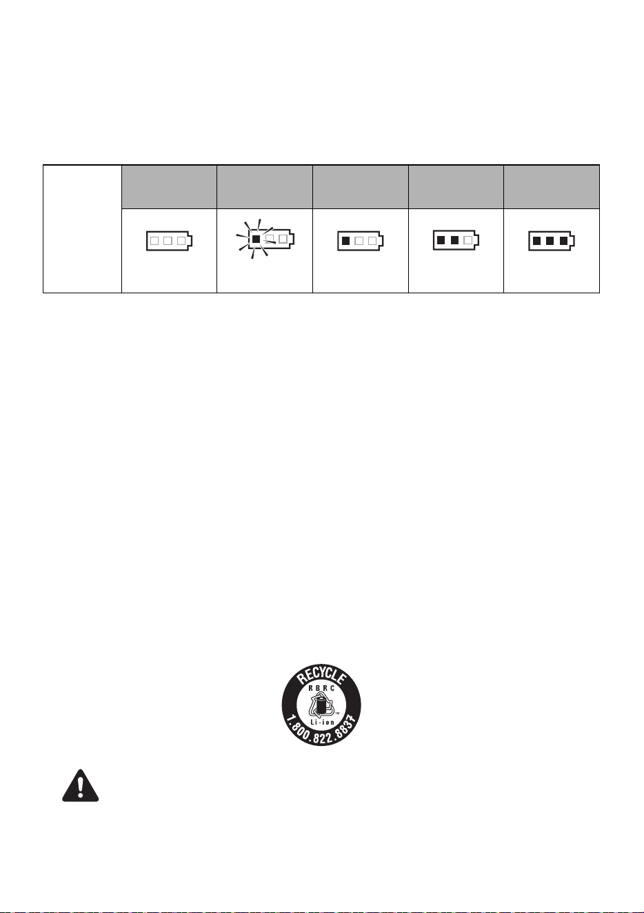
26
11. INSTRUCTIONS CONCERNANT LA BATTERIE
Information sur l’indicateur du niveau de batterie
(1) Pour vérifier le niveau de batterie (en dehors de la période de charge ou d’utilisation
de l’outil de charge), appuyez sur le bouton de vérification du niveau de batterie
(Fig. 47.I).
(2) La jauge de niveau de batterie (Fig. 47.J) s’allume en fonction du niveau de
batterie.
Durée de vie du bloc batterie
Si vous constatez l’une des conditions décrites ci-dessous, le bloc batterie est en fin de vie. Procédez à
son remplacement.
Bien que le bloc batterie soit correctement chargé (complètement chargé), vous constatez une baisse
importante de sa puissance au niveau du temps de ligature.
•
Ne chargez pas le bloc batterie dans ces conditions. En cas de ralentissement de la vitesse de
rotation du moteur, vous pouvez considérer le bloc batterie comme presque épuisé. Si vous
continuez à utiliser l’outil, vous provoquez sa décharge complète et risquez non seulement de
réduire la longévité du bloc batterie, mais également de provoquer un dysfonctionnement de l’outil.
• N’utilisez pas un bloc batterie en fin de vie.
•
Vous risquez de provoquer un dysfonctionnement de l’outil. Le fait de recharger un bloc batterie
qui est hors de service risque également de provoquer un mauvais fonctionnement du chargeur.
•
Ne jetez pas les blocs batteries/batteries au feu ou dans l’eau. Les blocs batteries/batteries
doivent être collectés, recyclés ou mis au rebut d’une manière respectueuse de l’environnement.
• Protégez la batterie contre la chaleur et l’exposition au soleil. Il existe un risque d’explosion.
• Chargez le bloc batterie à une température comprise entre 41 °F (5 °C) et 104 °F (40 °C).
Recyclage des batteries Li-ion
Le produit que vous avez acheté est alimenté par une batterie Li-ion recyclable. À la fin de sa durée de vie utile,
dans plusieurs États et conformément à plusieurs lois, il est illégal de mettre cette batterie au rebut dans les déchets
municipaux. Appelez le 1-800-8-BATTERY pour plus d'informations sur la manière de recycler cette batterie.
Le bloc batterie MAX contient des batteries Li-ion qu’il est interdit de jeter avec les ordures ménagères. Consultez
votre organisme local de collecte des déchets pour connaître les possibilités de recyclage ou de mise au rebut.
Lorsque vous mettez le bloc batterie au rebut, assurez-vous de placer un couvercle de batterie sur
ses contacts (en le fixant avec du ruban adhésif isolant) afin d’éviter un possible court-circuit.
Jauge du
niveau de
batterie
Niveau de
batterie :
0%
Niveau de
batterie :
environ 0 à 10 %
Niveau de
batterie :
environ 10 à 40 %
Niveau de
batterie :
environ 40 à 70 %
Niveau de
batterie :
environ 70 à 100 %
Tous les témoins
sont éteints
Un témoin
rouge clignote
Un témoin rouge
est allumé
Deux témoins
rouges sont allumés
Trois témoins
rouges sont allumés
AVIS
ATTENTION

27
12. UTILISATION
1. Méthode de réglage du fil à ligature
• Réglez l'interrupteur principal (Fig. 6.7) sur « OFF », le
verrouillage du déclencheur (Fig. 6.8) sur « LOCK » et
ôtez le bloc batterie (Fig. 6.0), lorsque vous changez le
bloc batterie, que vous remplacez ou réglez le fil à
ligature, en cas d'anomalie ou lorsque vous n'utilisez pas
l'outil.
1-1 (Fig. 9) Appuyez sur le levier de déclenchement (Fig. 9.3)
de l'équipement et vérifiez qu'il est maintenu par le pièce de
retenue de déclenchement (Fig. 92).
1-2 (Fig. 10) Décollez le ruban de fixation du fil à ligature
d’environ 5 cm (2"). Étirez l'extrémité du fil à ligature
enroulé.
Assurez-vous d'utiliser uniquement le fil à ligature
recommandé (série MAX TW898).
L'utilisation d'un fil autre que celui spécifié risque de provoquer la
panne de l'équipement. Par conséquent, veillez à n'utiliser que
du fil MAX TW898 spécifié. N'utilisez pas de fil à ligature rouillé,
car cela risquerait de provoquer une panne de l'équipement.
* Sur le TW897A, il est impossible d'utiliser une ancienne bobine
de fil.
1-3 (Fig. 11) Appuyez sur la pièce de retenue de la bobine
(Fig. 11.d) pour libérer le porte-bobine (Fig. 11.f).
1-4 (Fig. 12) Mettez en place le fil à ligature (Fig. 12.c) dans
l'outil en faisant correspondre le côté du fil à ligature comme
indiqué sur l'image. Appuyez ensuite sur le porte-bobine
(Fig. 12.f) et fixez-le en faisant glisser la pièce de retenue
de la bobine.
1-5 (Fig. 13) Insérez la pointe du fil à ligature étiré dans le
guide-fil (Fig. 13.m). Ensuite, placez-le dans le tuyau
(Fig. 13.n).
1-6 Placez le fil à environ 4" (10 cm) à l’intérieur du tuyau.
1-7 L'extrémité du fil à ligature doit être redressée pour lui
permettre de passer à travers le mécanisme d’alimentation
en fil. Lors du montage du fil à ligature, le fil risque de rester
coincé à l'intérieur de la machine si son extrémité est
tordue.
(Fig. 14) Si la fenêtre est sale et que la position du
tuyau ne peut pas être confirmée
Ouvrez la fenêtre et essuyez la saleté à l'intérieur avec un chiffon
doux, etc. Fermez la fenêtre après le nettoyage pour vous
assurer que des corps étrangers ne puissent pas pénétrer dans
la machine.
1-8 (Fig. 14) Libérez la pièce de retenue de déclenchement
(Fig. 14.2) et vérifiez que le levier de déclenchement
(Fig. 14.3) est revenu à sa position initiale et que les
engrenages d’alimentation (Fig. 14.l) serrent le fil à
ligature (Fig. 14.c). Ceci termine l'opération de montage
du fil à ligature.
1-9 Retirez complètement la bande du fil à ligature.
1-10 (Fig. 15) Éliminez le mou de la bobine de fil. Assurez-vous
que le fil à ligature ne se coince pas derrière la bobine de fil.
Cela pourrait entraîner un bourrage.
• (Fig. 16) Lors du réglage de l'interrupteur général sur ON,
ne placez pas la main près de l'élément de ligature ni de la
partie rotative de l'extrémité de l'outil.
• Ne touchez pas le fil à ligature pendant le travail de
ligature (lorsque l'outil est en fonctionnement).
• Ne pas allumer et éteindre l’interrupteur général en
succession rapide, car cela risquerait de provoquer des
pannes de la machine.
1-11 (Fig. 17) Insérez le bloc batterie sur l'outil jusqu'à ce que
vous entendiez un déclic. Allumez l'interrupteur général.
1-12 (RB518, RB218) (Fig. 37) L'outil alimente le fil d'environ
6" (150 mm) et le coupe automatiquement. Retirez
l'extrémité du fil avec une pince.
1-13 (Fig. 18) Réglez le verrou du déclencheur (Fig. 18.8) sur
la position UNLOCK avant d’utiliser l’outil.
2. Méthode de retrait du fil à ligature
• (Fig. 6) Réglez l'interrupteur principal (Fig. 6.7) sur
« OFF », le verrou du déclencheur (Fig. 6.8) sur « LOCK »
et ôtez le bloc batterie (Fig. 6.0).
2-1 (Fig. 9) Appuyez sur le levier de déclenchement (Fig. 9.3)
et vérifiez qu'il est maintenu par la pièce de retenue de
déclenchement (Fig. 92).
2-2 (Fig. 19) Retirez le fil à ligature (Fig. 19.c) du guide-fil
(Fig. 19.m).
2-3 (Fig. 12) Faites glisser la pièce de retenue de la bobine
(Fig. 12.d) pour libérer le support de la bobine (Fig. 12.f)
et retirez le fil à ligature (Fig. 12.c).
2-4 Montez le nouveau fil à ligature. (Reportez-vous à
l'explication de la méthode de montage du fil à ligature.)
3. Quand le fil à ligature est épuisé
Il devrait rester environ 12" (300 mm) de fil à ligature au bout de
la bobine. Celui-ci doit être déchargé avec l'ancienne bobine et
remplacé par une nouvelle.
4. (RB398S) Réglage de la tension
(Fig. 20) Cette molette (Fig. 20.5) vous permet de régler
légèrement le couple de tension du fil. Pour augmenter la
tension, tournez la molette dans le sens inverse des aiguilles
d'une montre. Pour réduire la tension, tournez la molette dans le
sens des aiguilles d'une montre.
4. (RB518) Réglage de la tension et des
spires
(Fig. 38) La molette de couple et des spires (Fig. 38.5) vous
permet de définir 3 spires/ligature ou 4 tours/ligature et vous
permet également de régler le couple.
Pour augmenter la tension, tournez la molette dans le sens
inverse des aiguilles d'une montre.
Pour réduire la tension, tournez la molette dans le sens des
aiguilles d'une montre.
4. (RB218) Réglage de la longueur du fil
(Fig. 40) La molette d'avance (Fig. 39.5) est un mécanisme
permettant de régler la vitesse d'alimentation du fil à ligature. Si
la longueur du bord (Fig. 40.x) ne convient pas après la ligature,
utilisez cette molette pour la régler.
5. Fonction d'arrêt automatique
Cet outil dispose d'une fonction d'« arrêt automatique » qui
permet d'économiser la batterie Li-ion lorsque l'outil n'est pas
utilisé. En cas de non utilisation pendant 30 minutes, l'outil
s'arrête automatiquement. Il s'agit de l'« Arrêt automatique ».
Pour remettre en marche l'outil après un arrêt automatique, réglez
l'interrupteur principal sur « OFF », puis à nouveau sur « ON ».
6. Méthode d’utilisation de RB398S/RB518/ RB218
Réglez l’interrupteur principal (Fig.6.7) sur « OFF », le
verrouillage du déclencheur (Fig.6.8) sur « LOCK » et ôtez
le bloc batterie (Fig.6.0).
6-1 (Fig.17) Insérez le bloc batterie dans le corps principal de
l’outil jusqu’à ce que vous entendiez un déclic.
6-2 Lorsque l’interrupteur principal (7) est sur « ON », le
crochet de l’extrémité tourne automatiquement pour
démarrer. Il est impératif de ne pas placer vos doigts à
proximité d’une pièce en rotation ou en mouvement. Réglez
l’interrupteur principal sur « ON » et le verrouillage du
déclencheur (8) sur « UNLOCK ».
6-3 (Fig. 22) Inclinez l'outil à 45° par rapport à l'intersection des barres.
AVERTISSEMENT
AVIS
AVERTISSEMENT
AVIS
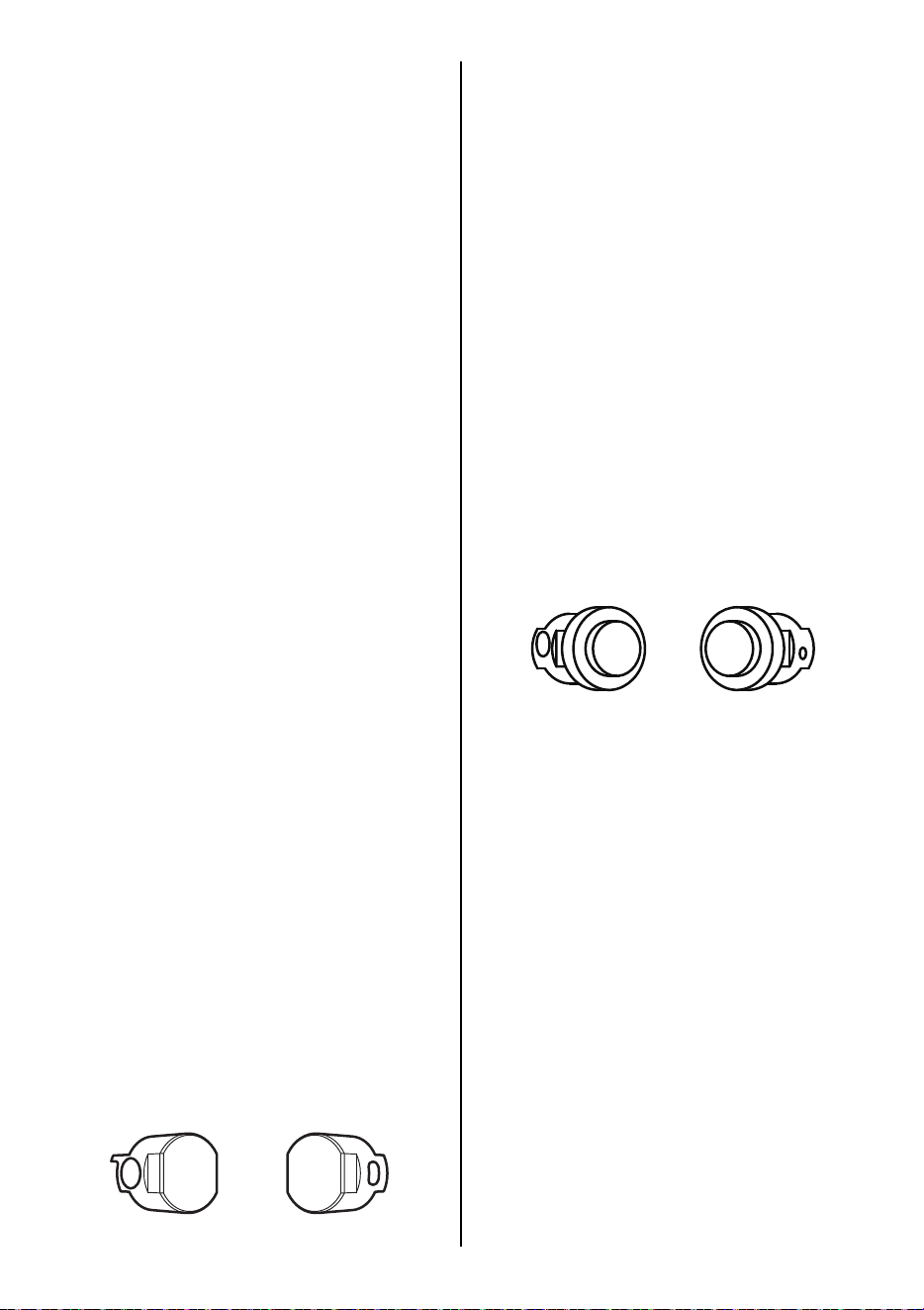
28
6-4 (Fig. 23) Placez l'outil perpendiculairement à la surface du
treillis d'armature.
6-5 Après avoir tiré le déclencheur, l’outil effectue
automatiquement une série d’actions de ligature
(chargement, coupe, saisie et ligature).
Pendant le fonctionnement
• Ne déplacez pas l'outil avant la fin automatique de
l'opération de ligature.
6-6 (Fig. 24) Alternez l'inclinaison des ligatures.
6-7 (Fig. 25) Faites une ligature croisée.
Pliez la queue de la première ligature avant d'effectuer la
seconde.
6-8 (Fig. 26) Lorsque vous avez besoin d'un serrage
supplémentaire, placez les barres (Fig. 26.a) en haut de la
partie du bras (Fig. 26.1).
13. MAINTENANCE
1-1 Inspectez régulièrement l'outil
Afin de maintenir les performances de l'outil, nettoyez et
inspectez-le régulièrement.
1-2 Ne pas lubrifier l'équipement
Ne lubrifiez surtout pas cet équipement. L'application d'une
lubrification éliminera la graisse à l'intérieur de l'outil et
causera des problèmes sur l'outil.
1-3 (Fig. 27) Nettoyez régulièrement le mécanisme
d'alimentation
Afin de maintenir les performances de l'outil, nettoyez
périodiquement le mécanisme autour du pignon
d'entraînement. À l’aide d'une soufflette pneumatique ou
autre, soufflez la poussière et la limaille de fer autour du
mécanisme d’alimentation.
1-4 Essuyez l'outil avec un chiffon doux et sec.
N'utilisez pas de chiffon humide ni de substances volatiles
telles que du diluant ou du benzène.
14. MANUEL DE NETTOYAGE
Lorsque la machine fonctionne pendant de longues heures, de la
poussière et des débris de fil peuvent adhérer à la section du
couteau. Dans ce cas, démontez et nettoyez la machine
conformément à la procédure suivante. (Si un fil est pris dans la
section du couteau ou dans le guide-fil A, vous pouvez le retirer
en suivant la même procédure.)
(RB398S)
Démontage
• N'ôtez pas les 2 boulons sans revêtement.
1-1 Desserrez les 2 boulons à tête à six pans creux (plaqués)
M3 × 6 (Fig. 28.o).
1-2 Retirez le bras B (Fig. 29.t) et les 2 boulons à tête à six
pans creux (plaqués) M3 × 6 (Fig. 29.o).
1-3 Retirez le couteau (Fig. 30.
p
) et le couteau fixe (Fig. 30.
r
) et
nettoyez-les. (Les pièces amovibles sont le couteau
(Fig. 30.
p
), le couteau fixe (Fig. 30.
r
), le guide-fil A
(Fig. 30.
q
) et l’unité de la plaque du couteau (Fig. 30.
s
).)
1-4 Essuyez l'outil avec un chiffon doux et sec.
N'utilisez pas de chiffon humide ni de substances volatiles
telles que du diluant ou du benzène.
Assemblage
• (Fig. 31) Assemblez le couteau fixe (Fig. 31.r) de sorte
que le grand trou (Fig. 31.b) soit placé à l’arrière et que le
petit trou (trou long) (Fig. 31.c) soit mis sur le dessus.
1-5 Insérez l'unité de la plaque du couteau (Fig. 31.s) dans le
trou de la tige de connexion du coupe-papier (Fig. 31.u) et
assemblez le couteau fixe (Fig. 31.r) sur l'unité.
1-6 Placez le couteau (Fig. 32.p) et assemblez le guide-fil A
(Fig. 32.q).
1-7 Alignez la rainure (Fig. 33.v) du guide-fil B (Fig. 33.w) fixé
au bras B (Fig. 33.t) sur le tuyau (Fig. 34.n) et
assemblez le bras B.
1-8 (Fig. 35) Assurez-vous que le bras B est solidement
assemblé et serrez les 2 boulons à tête à six pans creux
(plaqués) M3 × 6. (Fig. 35.o) (Couple de serrage :
15,5 lbf·in (175 cN·m))
• (Fig. 36) Y a-t-il des pièces qui se desserrent ?
Assurez-vous que les pièces extérieures sont alignées et que les
pièces sont assemblées de manière sûre, sans espace entre elles.
(RB518) (RB218)
Démontage
1-1 (Fig. 41) Desserrez les 2 boulons à tête à six pans creux
(plaqués) M3 × 5 (Fig. 41.y).
1-2 (Fig. 42) Retirez le bras B (Fig. 42.z) et les 2 boulons à
tête à six pans creux (plaqués) M3 × 6 (Fig. 42.y).
1-3 (Fig. 43) Retirez le couteau (Fig. 43.D) et le couteau fixe
(Fig. 43.C) et nettoyez-les. (Les pièces amovibles sont le
couteau, le couteau fixe et le boulon à gradins (Fig. 43.B).)
Assemblage
• (Fig. 44) Assemblez le couteau fixe (Fig. 44.C) de sorte
que le grand trou (Fig. 44.G) soit placé à l’arrière et le
petit trou (Fig. 43.H) sur le côté supérieur.
1-4 (Fig. 45) Insérez le boulon à gradins (Fig. 45.
B
) dans le trou,
puis dans le trou de la bielle de connexion (Fig. 43.
F
).
Assurez-vous que le boulon à gradins est complètement inséré.
1-5 (Fig. 46) Assurez-vous que le bras B (Fig. 41.z) est
solidement assemblé et serrez les 2 boulons à tête à six
pans creux (plaqués) M3 × 5 (Fig. 46.y). (Couple de
serrage : 15,5 lbf·in (175 cN·m))
•
Le boulon (droit) (Fig. 46.
y
) devrait avoir la rondelle
(Fig. 46.
E
). Installez d'abord la rondelle puis serrez le boulon.
15. ENTREPOSAGE
Ne pas entreposer l’outil dans un endroit exposé au froid. Le
conserver dans un endroit chaud. Si l’outil reste inutilisé, il faut le
conserver dans un endroit chaud et sec. Le mettre hors de portée
des enfants. Tous les outils de qualité nécessiteront
éventuellement un entretien ou un remplacement de pièces en
raison de l'usure normale.
(Fig. 21) Retirer la bobine de fil à ligature
Lorsque vous avez fini d'utiliser le fil à ligature, ôtez-le de l'outil.
Rangement de l'outil
Lorsque vous avez terminé vos travaux de ligature ou lorsque vous
n'utilisez plus l'outil, mettez-le hors tension, assurez-vous que le
moteur est arrêté, verrouillez le déclencheur et retirez le module
batterie. L'outil et ses accessoires doivent être rangés dans un endroit
sec et bien aéré où la température ne dépasse pas 104 °F(40 °C). Afin
d'éviter un possible court-circuit, le bloc batterie, avec le couvercle en
place sur la borne du bloc, doit être rangé dans un endroit sec et bien
aéré où la température ne dépasse pas 86 °F(30 °C).
AVIS
AVIS
Côté arrière Côté supérieur
AVIS
AVIS
Côté arrière Côté supérieur
AVIS

29
16. DÉPANNAGE/RÉPARATION
Le dépannage et/ou les réparations ne doivent être effectués que par MAX CO., LTD. distributeurs agréés ou par d'autres spécialistes.
Cet outil vous avertit des conditions suivantes au moyen d'un avertisseur sonore et d'un voyant. Le voyant est allumé ou clignote et est
associé au son d'avertissement. Prenez une contre-mesure conformément au tableau suivant.
• Si l’une des conditions suivantes se présente, assurez-vous de placer l’interrupteur principal (Fig. 1.7) sur OFF avant
d’exécuter les mesures correctives.
• Lorsque vous réglez l'interrupteur principal sur ON, ne touchez pas la partie liant de la partie rotative de la pointe de l'outil.
Si le problème n'est pas résolu en appliquant les mesures correctives suivantes, veillez à régler l'interrupteur principal sur
OFF, puis contactez le revendeur auprès duquel vous avez acheté l'équipement ou MAX CO., LTD. distributeurs autorisés.
N°
Fonctionnement
normal
Problème
Son
d'avertissement
Cause Point à vérifier Solution
1. Mise sous tension
→ L'axe d'extrémité
est initialisé et le
coupe-fil
fonctionne.
Aucune
opération n'a
lieu.
Aucun son n'est
émis.
Batterie morte
(complètement vide)
Vérifiez que la batterie
est chargée.
Effectuer une charge
normale.
La plaque
d'électrode est
oxydée.
En retirant la batterie,
voyez si l’électrode a été
dorée.
Frottez les bornes de la
batterie avec un chiffon
sec, etc.
Un long bip
(Biiip...)
Le guide de
bouclage (Fig. 1.b)
est resté ouvert.
Ouvrir/fermer le guide de
bouclage
Fermer complètement le
guide de bouclage.
Bips courts
continus
(Pi, pi, pi, ...)
Le fil de ligature s'est
emmêlé autour de la
section de torsion.
Coupez le courant et
retirez la batterie pour
vérifier si le fil à ligature
est emmêlé dans le guide
de bouclage.
Coupez l'alimentation,
retirez le fil à ligature à
l'intérieur du guide de
bouclage.
Deux bips courts
répétés pendant
10 secondes (Bip
bip, bip bip, ...),
puis s'éteint
automatiquement
La batterie est vide. Vérifiez que la batterie
est chargée.
Effectuer une charge
normale.
Le bloc batterie est
inséré lorsque
l’interrupteur
principal est sur ON.
Assurez-vous d'insérer le
bloc batterie uniquement
lorsque l'interrupteur
principal est sur OFF.
Réglez le commutateur
principal sur OFF, puis
sur ON.
2. Mise sous tension
→ La témoin LED
est allumé. →
Aucune opération
plus de 30 minutes
→ Le témoin LED
s'éteint. → Bien que
l'on appuie sur le
déclencheur,
aucune opération
n'a lieu.
Aucune
opération n'a
lieu, même si
vous appuyez
sur le
déclencheur
Aucun son n'est
émis
Fonctionnement
normal.
Réglez le commutateur
principal sur OFF, puis
sur ON.
Réglez le commutateur
principal sur OFF, puis
sur ON.
3. Déclencheur activé
→ Le fil sort.
La sortie du fil
n'a pas lieu.
Un long bip
(Biiip...)
Le guide de
bouclage est resté
ouvert.
Ouvrir/fermer le guide de
bouclage
Fermer complètement le
guide de bouclage.
Trois bips
courts répétés
(Bip bip bip,
bip bip bip, ...)
Le fil à ligature est
épuisé.
Vérifiez si le fil à ligature
est épuisé ou non.
Mettez en place un
nouveau fil à ligature.
Fil coincé dans la
bobine.
Vérifiez si le fil à
l'intérieur de la bobine a
été desserré et se trouve
coincé.
Éliminez
l'enchevêtrement au
niveau de la bobine.
La section du
couteau (Fig. 29) est
bloquée par une
substance
étrangère.
Confirmez le
fonctionnement de la
section du couteau.
Essuyez la section du
couteau avec un chiffon
sec ou soufflez dessus
avec de l’air.
Un fil est pris dans la
section du couteau
ou dans le guide-fil A
(Fig. 29.q).
Vérifiez si un fil est
coincé.
Démontez la section du
couteau et retirez le fil
coincé. (Fig. 28~36)
Cinq bips courts
(Bip bip bip bip
bip, bip bip bip
bip bip)
Le moteur
surchauffe.
Le son d'avertissement
n'est pas émis
continuellement. Il se
produit uniquement
lorsque le déclencheur
est pressé.
Arrêtez la machine et
laissez-la refroidir.
AVERTISSEMENT

30
3. Déclencheur activé
→ Le fil sort.
Le chargement
du fil est arrêté
à mi-chemin.
Quatre bips
courts répétés
(Bip bip bip bip,
bip bip bip bip, ...)
Le fil à ligature n'est
pas en place dans
l'outil.
Vérifiez si le fil à ligature
est en place dans l'outil.
Mettez en place le fil à
ligature.
Un fil à ligature d'un
type non prévu a été
utilisé.
Vérifiez côté bobine. Utilisez un fil à ligature
MAX TW898.
Trois bips
courts répétés
(Bip bip bip,
bip bip bip, ...)
Le fil de ligature s'est
emmêlé à l'intérieur
de la bobine.
Vérifiez l'enroulement de
la bobine.
Éliminez
l'enchevêtrement au
niveau de la bobine.
4. Le fil à ligature
dessine un cercle.
La boucle est
désordonnée
et sort du guide
de bouclage.
Aucun son n'est
émis.
Le fil a été repoussé
en heurtant les
barres d'armature.
Vérifiez si le fil touche les
barres d’armature
pendant la ligature.
Faites attention à ce que
le fil ne heurte pas les
barres d'armature
pendant la ligature.
5. Le fil est sujet à la
coupe.
Aucune
coupure de fil
n'a lieu.
Bips courts
continus.
(Bip biiip bip
biiip...)
La section du
couteau est bloquée
par une substance
étrangère.
Confirmez le
fonctionnement de la
section du couteau.
Essuyez la section du
couteau avec un chiffon
sec ou soufflez dessus
avec de l’air.
6. La torsion du fil a
lieu.
Le fil est
emmêlé.
Aucun son n'est
émis.
Le fil a été repoussé
en heurtant les
barres d'armature.
Vérifiez si le fil touche les
barres d’armature
pendant la ligature.
Faites attention à ce que
le fil ne heurte pas les
barres d'armature
pendant la ligature.
Un bip court et
un bip long, à
plusieurs
reprises.
(Bip biiip bip
biiip...)
Le fil de ligature s'est
emmêlé autour de la
section de torsion.
Coupez le courant et
retirez la batterie pour
vérifier si le fil à ligature
est emmêlé dans le guide
de bouclage.
Coupez l'alimentation,
retirez le fil à ligature à
l'intérieur du guide de
bouclage.
La résistance
des ligatures
est faible.
Aucun son n'est
émis.
Les barres
d'armature n'ont pas
la taille indiquée.
Confirmez la taille des
barres d'armature à lier.
(VOIR PAGE 25)
Utilisez un diamètre
approprié.
Manipulation
erronée telle qu'une
mauvaise
application de la
machine.
Vérifiez comment
appliquer la machine sur
les barres d’armature.
En tournant la cadran à
couple (Fig. 1.5) sur +
et en l'insérant dans le
sens vertical, utilisez-le
selon une inclinaison à
45 °. (Fig. 22)
Fonction du
commutateur du
guide de bouclage
Vérifiez si le guide de
bouclage est laissé
ouvert à la ligature.
Ne pas utiliser la
machine tant que la
ligature n’est pas
terminée.
La torsion a
lieu.
Aucun son n'est
émis.
Les barres
d'armature n'ont pas
la taille indiquée.
Confirmez la taille des
barres d'armature à la
ligature.
(VOIR PAGE 25)
Utilisez un diamètre
approprié.
Manipulation
erronée telle qu'une
mauvaise
application de la
machine.
Vérifiez comment
appliquer la machine sur
les barres d’armature.
En tournant le cadran à
couple sur - (moins) et
en l'insérant dans le
sens vertical, utilisez-le
selon une inclinaison à
45 °. (Fig. 22)
Fonctionne
correctement
Deux bips
courts.
(Bip bip)
Il reste peu d’énergie
dans la batterie.
Vérifiez que la batterie
est complètement
chargée.
Effectuez une charge
normale quand la vitesse
de ligature ralentit
considérablement.
L'outil est utilisé à
basse température.
Vérifiez la température
sur le chantier.
Laissez l'outil et le
module batterie à la
température normale
dans la pièce pendant un
certain temps, puis
continuez l'opération.
N°
Fonctionnement
normal
Problème
Son
d'avertissement
Cause Point à vérifier Solution

31
ÍNDICE
1. NOMBRE DE LAS PIEZAS ............................................................................................................................. 31
2. LISTA DE CONTENIDOS................................................................................................................................ 32
3. ADVERTENCIAS GENERALES DE SEGURIDAD SOBRE LA HERRAMIENTA ELÉCTRICA .................... 32
4. CARACTERÍSTICAS DE SEGURIDAD RB398S/RB518/RB218 ................................................................... 34
5. DATOS TÉCNICOS Y ESPECIFICACIONES DE LA HERRAMIENTA.......................................................... 36
6. DATOS TÉCNICOS......................................................................................................................................... 37
7. AÑO DE PRODUCCIÓN.................................................................................................................................. 37
8. ESPECIFICACIONES DEL ALAMBRE........................................................................................................... 38
9. APLICACIONES .............................................................................................................................................. 38
10. TAMAÑO DE ARMADURA APLICABLE........................................................................................................ 38
11. INSTRUCCIONES DE LA BATERÍA............................................................................................................... 39
12. INSTRUCCIONES DE FUNCIONAMIENTO ................................................................................................... 40
13. MANTENIMIENTO........................................................................................................................................... 41
14. MANUAL DE LIMPIEZA.................................................................................................................................. 41
15. ALMACENAMIENTO....................................................................................................................................... 41
16. SOLUCIÓN DE PROBLEMAS/REPARACIONES .......................................................................................... 42
DEFINICIONES DE LAS SEÑALES INDICATIVAS
ADVERTENCIA: indica una situación peligrosa que, si no se evita, puede provocar lesiones graves o incluso
la muerte.
PRECAUCIÓN: indica una situación peligrosa que, si no se evita, puede provocar lesiones leves o
moderadas.
AVISO: indica un mensaje relativo a posibles daños materiales.
1. NOMBRE DE LAS PIEZAS
Fig.1
Fig. 2 Paquete de baterías
Fig.3 Cargador de baterías
Consulte el manual de funcionamiento y mantenimiento del
cargador JC925A.
Fig.13 a Fig.47
ESPAÑOL
MANUAL DE INSTRUCCIONES E INSTRUCCIONES DE SEGURIDAD
1 Brazo
2 Bloqueo
3 Palanca de liberación
4 Visor
5 Disco selector de par (RB398S)
Disco selector de par y envoltura (RB518)
Disco selector de avance (RB218)
6 LED
7 Interruptor principal
8 Seguro del disparador
9 Empuñadura
0 Paquete de baterías
a Disparador
b Guía de curvado
c Alambre de amarre
d Tope de bobina
e Año y número de fabricación
f Portabobinas
g Gancho para cinturón
h Cierre
i Tapa del paquete
j Terminal
l Engranaje de alimentación
m Guía del alambre
n Tubo
o Pernos de cabeza hueca hexagonal M3 × 6
p Cortadora
q Guía del alambre A
r Cortadora fija
s Unidad de placa fresadora
Traducción de las
instrucciones originales
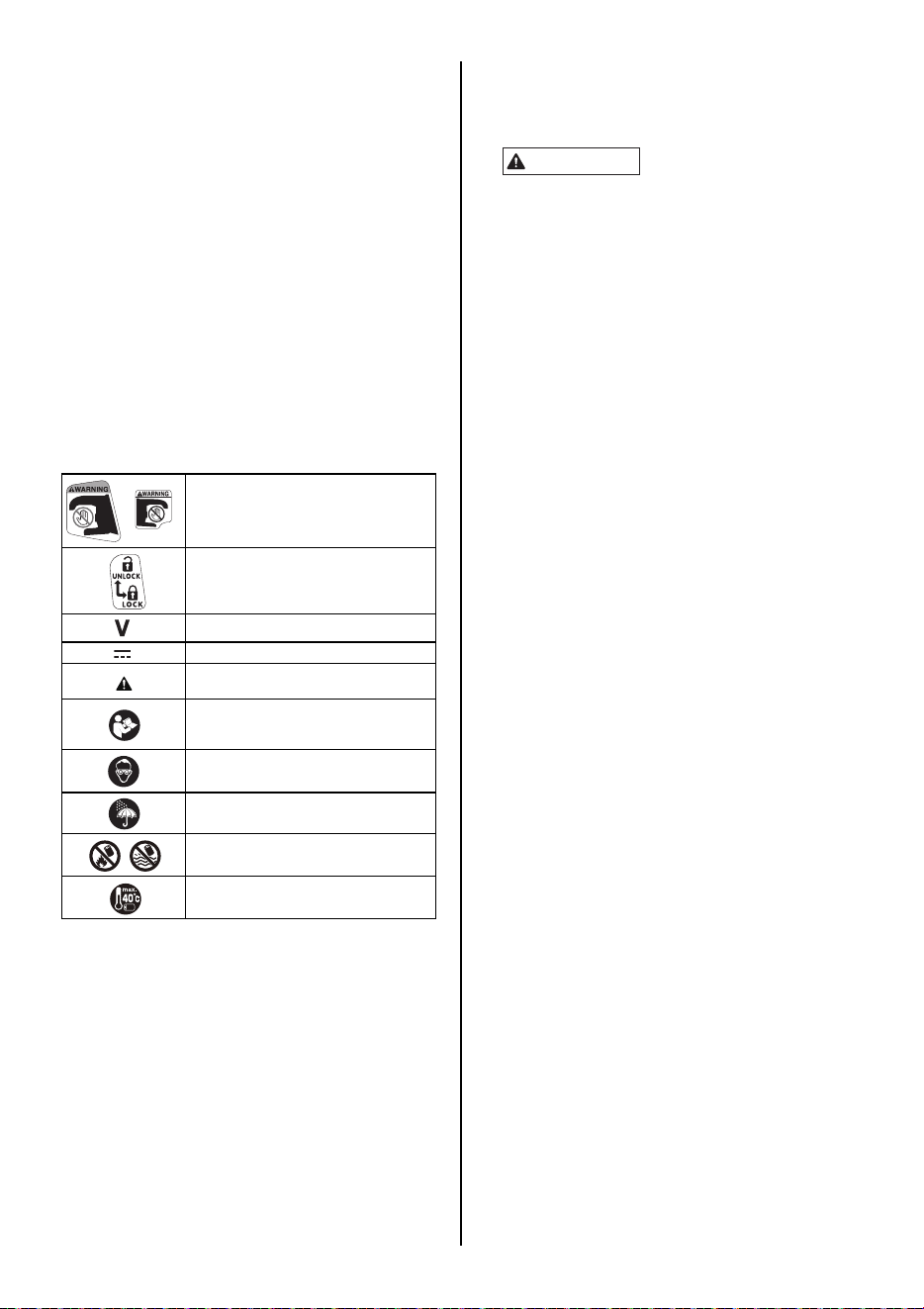
32
Símbolos
A continuación encontrará los símbolos utilizados en la máquina.
2. LISTA DE CONTENIDOS
• Atadora de armaduras de refuerzo MAX /
RB398S/RB518/RB218
• Paquete de baterías de ion litio / JPL91450A
• Cargador de baterías de ion litio / JC925A
• Cable de alimentación eléctrica
• Gancho para cinturón
• MANUAL DE INSTRUCCIONES E
INSTRUCCIONES DE SEGURIDAD (este libro)
3. ADVERTENCIAS GENERALES DE
SEGURIDAD SOBRE LA
HERRAMIENTA ELÉCTRICA
1. Seguridad en la zona de trabajo
• Mantenga la zona de trabajo limpia y bien iluminada.
Las zonas de trabajo abarrotadas u oscuras propician los
accidentes.
• No utilice la herramienta eléctrica en atmósferas
explosivas, como por ejemplo en presencia de
líquidos inflamables, gases o polvo. Las herramientas
eléctricas generan chispas que pueden prender fuego al
polvo o a los humos.
• Mantenga alejados a los niños y a los curiosos
mientras utiliza la herramienta eléctrica. Las
distracciones pueden hacerle perder el control.
2. Seguridad eléctrica
• Los enchufes de las herramientas eléctricas deben
guardar correspondencia con la toma de corriente.
Nunca modifique el enchufe de ninguna manera. No
utilice ningún enchufe adaptador con las
herramientas eléctricas conectadas a tierra. Los
enchufes sin modificaciones y en correspondencia con
las tomas de corriente reducirán el riesgo de descarga
eléctrica.
• Evite el contacto corporal con las superficies
conectadas a tierra, como tuberías, radiadores,
estufas y neveras. Si su cuerpo está conectado a tierra
el riesgo de descarga eléctrica es mayor.
• No exponga las herramientas eléctricas a la lluvia o la
humedad. La entrada de agua a una herramienta
eléctrica aumentará el riesgo de descarga eléctrica.
• Trate el cable con cuidado. No lo use nunca para
trasladar, arrastrar o desenchufar la herramienta
eléctrica. Mantenga el cable alejado del calor, el
aceite, los bordes cortantes y las piezas móviles. Los
cables dañados o enredados aumentan el riesgo de
descarga eléctrica.
•
Cuando use una herramienta eléctrica en el exterior,
hágalo utilizando un cable de extensión adecuado.
El
uso de un cable adecuado para utilización en el exterior
reduce el riesgo de descarga eléctrica.
• Si la utilización de una herramienta eléctrica en un
lugar mojado es inevitable, use un dispositivo de
corriente residual (RCD) con suministro protegido. La
utilización de un RCD reduce el riesgo de descarga
eléctrica.
3. Seguridad personal
•
Cuanto utilice una herramienta eléctrica permanezca
alerta, preste atención a lo que hace y aplique el sentido
común. No utilice una herramienta eléctrica si está
cansado o bajo los efectos de drogas, bebidas
alcohólicas o medicamentos.
Un instante de descuido
durante la utilización de herramientas eléctricas puede
provocar graves lesiones personales.
• Use equipo de protección personal. Use siempre
protección ocular. El equipo de protección, como
máscara antipolvo, zapatos de seguridad antideslizantes,
t Brazo B
u Orificio de biela de la cortadora
v Ranura
w Guía del alambre B
x Filo
y Pernos de cabeza hueca hexagonal M3 × 5
z Brazo B
A Guía del alambre A
B Pasador de paso
C Cortadora fija
D Cortadora
E Arandela
F Biela
G Orificio grande
H Orificio pequeño
I Botón de comprobación de nivel de la batería
J Indicador de nivel de la batería
Mantenga las manos y el cuerpo
alejados de la guía de curvado y del
brazo.
DESBLOQUEAR
BLOQUEADO
Tensión nominal
Corriente directa
PRECAUCIÓN
ADVERTENCIA
Lea el manual de instrucciones y las
instrucciones de seguridad antes de
utilizar la herramienta.
Utilice gafas de seguridad.
No la exponga a la lluvia.
No arroje las baterías o paquetes de
baterías al fuego ni al agua.
Proteja la batería frente el calor, la
radiación solar continua y el fuego.
Lea todas las advertencias de seguridad, instrucciones,
ilustraciones y especificaciones proporcionadas con
esta herramienta eléctrica. Si no respeta todas las
instrucciones enumeradas abajo pueden producirse
descargas eléctricas, incendios y/o lesiones graves.
Conserve todas las advertencias e instrucciones para
futuras consultas.
El término "herramienta eléctrica" indicado en las
advertencias se refiere a la herramienta conectada
(mediante cables) a la red eléctrica o accionada por batería
(inalámbrica).
ADVERTENCIA

33
casco y protección auditiva, utilizado en las condiciones
apropiadas reducirá el riesgo de lesiones personales.
• Prevenga la puesta en marcha accidental. Antes de
conectar la herramienta a la red de alimentación
eléctrica y/o al paquete de baterías, recogerla o
trasladarla, asegúrese de que el interruptor esté en la
posición "off" ("desconectado"). El traslado de las
herramientas eléctricas con el dedo en el interruptor o con
el interruptor en la posición "on" propicia los accidentes.
• Antes de poner en marcha la herramienta retire de la
misma toda llave de ajuste o llave inglesa. Una llave
inglesa o llave de ajuste sujeta a una pieza giratoria de la
herramienta eléctrica puede provocar lesiones
personales.
• Vístase adecuadamente. No use ropa holgada ni
joyas. Mantenga el cabello y la ropa alejados de las
piezas móviles. Las prendas holgadas, las joyas o el
cabello largo pueden quedar atrapados en las piezas
móviles.
• Vístase adecuadamente. No use ropa holgada ni
joyas. Mantenga el cabello, la ropa y los guantes
alejados de las piezas móviles. Las prendas holgadas,
las joyas o el cabello largo pueden quedar atrapados en
las piezas móviles.
• Si la herramienta tiene dispositivos para recogida y
extracción de polvo, asegúrese de que están
conectados y se utilizan adecuadamente. El uso del
dispositivo de recogida de polvo puede reducir los
peligros relacionados con el mismo.
• No deje que la familiaridad adquirida por el uso
frecuente de herramientas le haga bajar la guardia e
ignorar los principios de seguridad de la herramienta.
Un descuido puede provocar lesiones graves en una
fracción de segundo.
4. Uso y cuidado de la herramienta eléctrica
• No fuerce la herramienta eléctrica. Use la herramienta
eléctrica adecuada a sus necesidades. La herramienta
eléctrica adecuada hará mejor el trabajo y de manera más
segura a la velocidad para la que fue diseñada.
• No use la herramienta eléctrica si el interruptor no
conmuta entre las posiciones "on" ("conectado") y
"off" ("desconectado"). Toda herramienta eléctrica que
no puede controlarse con el interruptor es peligrosa y
debe repararse.
• Desconecte el enchufe de la red eléctrica y/o retire el
paquete de baterías, si es extraíble, de la herramienta
antes de guardarla o de realizar ajustes o cambios de
accesorios. Estas medidas de seguridad preventivas
reducen el riesgo de puesta en marcha accidental de la
herramienta eléctrica.
• Guarde las herramientas eléctricas fuera de uso
alejadas del alcance de los niños y no deje que las
utilicen personas no familiarizadas con las mismas o
con estas instrucciones. El uso de herramientas
eléctricas por personas que carecen de la formación
necesaria resulta peligroso.
• Realice el mantenimiento de las herramientas
eléctricas y de sus accesorios. Compruebe que las
piezas móviles estén bien alineadas y sujetas, y que
ninguna pieza esté dañada o en un estado que pueda
afectar al funcionamiento de la herramienta eléctrica.
Si detecta alguna avería, haga reparar la herramienta
eléctrica antes de usarla. El mantenimiento deficiente
de las herramientas eléctricas provoca muchos
accidentes.
• Mantenga las herramientas de corte afiladas y
limpias. Las herramientas de corte adecuadamente
mantenidas y con los bordes afilados tienen menos
probabilidades de atascarse y son más fáciles de
controlar.
• Use la herramienta eléctrica, los accesorios, las
piezas, etc. de acuerdo con estas instrucciones,
teniendo en cuenta las condiciones de trabajo y la
tarea que debe realizar. El uso de la herramienta
eléctrica para trabajos que no sean los previstos podría
provocar una situación peligrosa.
• Mantenga las empuñaduras y las superficies de
agarre secas, limpias y libres de aceite y grasa. Las
empuñaduras y superficies de agarre resbaladizas
impiden manipular y controlar la herramienta con
seguridad en situaciones imprevistas.
5. Uso y cuidado de la batería de la herramienta
• Recargue la batería únicamente con el cargador
especificado por el fabricante. Un cargador apto para
un determinado tipo de paquete de baterías puede
provocar riesgo de incendio si se utiliza con otro tipo de
paquete de baterías.
• Use las herramientas eléctricas sólo con los paquetes
de batería diseñados específicamente. El uso de
cualquier otro paquete de baterías puede provocar riesgo
de lesiones e incendio.
• Cuando el paquete de baterías esté fuera de uso,
manténgalo alejado de otros objetos metálicos, como
clips para papeles, monedas, llaves, clavos, tornillos
u otros objetos metálicos pequeños que pueden
establecer la conexión entre un terminal y otro. La
unión de los terminales de baterías puede causar
quemaduras o provocar un incendio.
• En condiciones de uso inadecuadas la batería puede
proyectar líquido, cuyo contacto es necesario evitar.
Si accidentalmente entra en contacto con dicho
líquido, lávese bien con agua. Si el líquido entra en
contacto con los ojos, lávese con agua y acuda al
médico. El líquido proyectado por la batería puede
causar irritación o quemaduras.
• No utilice una herramienta o un paquete de baterías
que estén dañados o hayan sido modificados. Las
baterías dañadas o modificadas pueden presentar un
comportamiento impredecible y provocar un incendio, una
explosión o lesiones.
• No exponga el paquete de baterías ni la herramienta
al fuego o a una temperatura excesiva. La exposición
al fuego o a temperaturas superiores a 130 °C puede
provocar una explosión.
• Siga todas las instrucciones de carga y no cargue el
paquete de baterías ni la herramienta fuera del
intervalo de temperatura especificado en las
instrucciones. Una carga realizada de forma inadecuada
o a una temperatura fuera del intervalo especificado
puede producir daños en la batería y aumentar el riesgo
de incendio.
6. Servicio
• La reparación de la herramienta eléctrica debe
confiarse a un técnico cualificado que utilice
únicamente las piezas de recambio originales. De esta
manera se garantizará la seguridad de la herramienta
eléctrica.
• Nunca repare un paquete de baterías dañado. La
reparación de un paquete de baterías sólo puede ser
realizada por el fabricante o por proveedores autorizados
de servicio técnico.

34
4. CARACTERÍSTICAS DE
SEGURIDAD RB398S/RB518/RB218
1. REVISE LAS PIEZAS ANTES DE MONTAR EL
PAQUETE DE BATERÍAS
• Compruebe que los tornillos están bien ajustados.
Un ajuste insuficiente puede provocar un accidente o
una avería en la herramienta. Si un tornillo está flojo,
vuelva a apretarlo a fondo.
•
Revise las piezas para comprobar que no presentan
daños.
Las piezas se deterioran con el uso. Compruebe también
que no faltan piezas y que no son defectuosas o de mala
calidad. Si hay alguna pieza que deba reemplazarse o
repararse, diríjase al proveedor donde compró la
herramienta o a un distribuidor autorizado por MAX CO.,
LTD.
Use únicamente las piezas de recambio originales
autorizadas.
2. COLOQUE EL INTERRUPTOR PRINCIPAL (FIG.6.7)
EN LA POSICIÓN "OFF" ("DESCONECTADO"),
COLOQUE EL SEGURO DEL DISPARADOR
(FIG.6.8) EN LA POSICIÓN "LOCK"
("BLOQUEADO") Y EXTRAIGA EL PAQUETE DE
BATERÍAS (FIG.6.0) CUANDO CAMBIE EL
PAQUETE DE BATERÍAS, SUSTITUYA O AJUSTE
EL ALAMBRE DE AMARRE, SE PRODUZCA
CUALQUIER ANOMALÍA O LA HERRAMIENTA
ESTÉ FUERA DE USO
Si se deja la herramienta activada en esas situaciones,
pueden producirse lesiones o averías.
3. MANTENGA LOS DEDOS Y EL CUERPO
APARTADOS DEL BRAZO Y DE LA GUÍA DE
CURVADO EN TODO MOMENTO (FIG.16)
El incumplimiento de esta advertencia puede provocar
lesiones graves.
4. MANTENGA LOS DEDOS Y EL CUERPO
APARTADOS DEL ALAMBRE DE AMARRE
CUANDO LA HERRAMIENTA ESTÉ EN
FUNCIONAMIENTO
El incumplimiento de esta advertencia puede provocar
lesiones graves.
5. NO APUNTE A NADIE CON LA HERRAMIENTA
Si la herramienta atrapa al operario o a alguien que esté
trabajando cerca de él podría provocarle lesiones. Cuando
trabaje con la herramienta, tenga sumo cuidado de no
acercar las manos, las piernas u otras partes del cuerpo al
brazo de la misma.
6. CUANDO LA HERRAMIENTA NO ESTÉ EN
FUNCIONAMIENTO, QUITE LOS DEDOS DEL
DISPARADOR
El incumplimiento de esta advertencia puede ocasionar el
accionamiento accidental de la herramienta y provocar
lesiones graves.
7. NUNCA HAGA FUNCIONAR LA HERRAMIENTA EN
CONDICIONES ANÓMALAS
Si la herramienta no está en buenas condiciones de
funcionamiento, o si observa alguna anomalía, desconéctela
inmediatamente (coloque el interruptor principal en la
posición "OFF"), bloquee el disparador y haga que la revisen
y la reparen.
8. DESPUÉS DE LA INSTALACIÓN DE LA BATERÍA, SI
LA HERRAMIENTA SE PONE EN MARCHA SIN
ACCIONAR EL DISPARADOR O SI EL OPERARIO
ADVIERTE UN CALENTAMIENTO, OLOR O SONIDO
INUSUALES, DEBE INTERRUMPIRSE EL
FUNCIONAMIENTO
El incumplimiento de esta advertencia puede provocar
lesiones graves. Lleve la herramienta al distribuidor para que
reciba una inspección de seguridad.
9. NUNCA MODIFIQUE LA HERRAMIENTA
La modificación de la herramienta incidirá negativamente en
el rendimiento y en la seguridad de funcionamiento.
Cualquier modificación de la herramienta puede provocar
lesiones graves y dar lugar a la anulación de la garantía.
10. MANIPULE LA HERRAMIENTA CON CUIDADO
Si la deja caer o sufre algún impacto, podría provocar
averías o daños.
11. MANTENGA LA HERRAMIENTA EN BUENAS
CONDICIONES DE FUNCIONAMIENTO
Para garantizar un funcionamiento seguro y el máximo
rendimiento, proteja a la herramienta de las averías y el
desgaste. Además, mantenga limpia y seca la empuñadura
de la herramienta, especialmente sin aceite o grasa.
12. USE ÚNICAMENTE EL PAQUETE DE BATERÍAS
AUTORIZADO
Si está conectada a una fuente de energía que no es el
paquete autorizado, como por ejemplo una batería
recargable, una pila seca o un acumulador para
automóviles, la herramienta puede resultar dañada, sufrir
averías, recalentarse o incluso incendiarse. No conecte esta
herramienta a ninguna fuente de energía que no sea el
paquete de baterías autorizado.
13. PARA GARANTIZAR EL MÁXIMO RENDIMIENTO,
CARGUE POR COMPLETO LA BATERÍA ANTES DE
USARLA
Un paquete de baterías nuevo o que ha estado en desuso
durante un período prolongado puede haberse descargado;
en ese caso, es necesario volver a cargarlo al máximo de su
capacidad. Antes de poner en funcionamiento la
herramienta, asegúrese de cargar el paquete de baterías
con el cargador de baterías de MAX especificado.
14. PRECAUCIÓN PARA LA CARGA DE LA BATERÍA
14-1 Use únicamente el cargador de baterías de
MAX y el paquete de baterías de MAX.
El incumplimiento de esta indicación puede provocar
el recalentamiento o el incendio de la batería, lo cual
ocasionaría lesiones graves.
14-2 Cargue la batería en un enchufe de pared
de 100-240 V CA.
El incumplimiento de esta indicación puede provocar
recalentamiento o una carga inadecuada, lo cual
posiblemente ocasionaría lesiones graves.
14-3 Nunca use un transformador.
14-4 Nunca conecte el cargador de baterías al
suministro eléctrico de corriente continua
de un grupo electrógeno.
El cargador se incendiará y sufrirá averías o daños.
14-5 Evite cargar el paquete de baterías bajo la
lluvia, en un lugar húmedo o donde haya
salpicaduras de agua.
La carga del paquete de baterías en un lugar mojado
o húmedo provocará una descarga eléctrica o un
cortocircuito que puede causar quemaduras e incluso
incendiar la herramienta.
14-6 No toque el cable de alimentación ni el
enchufe con las manos o los guantes
húmedos.
La descarga eléctrica podría causarle lesiones.
14-7 No cubra el cargador de baterías con un
paño u otro objeto mientras se carga el
paquete de baterías.
Si lo hace, el cargador podría recalentarse y
provocarle quemaduras e incluso incendiarse.
14-8 Mantenga el paquete de baterías y el
cargador de baterías alejados del calor y
las llamas.
14-9 No cargue el paquete de baterías cerca de
materiales inflamables.

35
14-10 Cargue el paquete de baterías en un lugar
bien ventilado.
Evite cargar el paquete de baterías en un lugar en el
que esté expuesto a la luz solar directa.
14-11 Cargue el paquete de baterías en un
intervalo de temperatura de 41 °F (5 °C) a
104°F (40°C).
14-12 Evite el uso continuo del cargador de
baterías.
Deje descansar al cargador durante 15 minutos entre
una y otra carga para evitar problemas de
funcionamiento en la unidad.
14-13 Todo objeto que bloquee los orificios de
ventilación o el receptáculo del paquete de
baterías puede provocar descarga
eléctrica o problemas de funcionamiento.
Haga funcionar el cargador sin que tenga polvo u
otros materiales extraños.
14-14 Manipule con cuidado el cable de
alimentación.
No traslade el cargador de baterías sujetándolo por el
cable de alimentación. No tire del cable de
alimentación para desconectarlo del enchufe de
pared; el cable resultará dañado y se romperán los
hilos o se producirá un cortocircuito. No deje que el
cable de alimentación entre en contacto con
herramientas de bordes afilados, materiales calientes,
aceite o grasa. Si el cable está dañado es necesario
repararlo o cambiarlo.
14-15 No use este cargador para cargar baterías
no recargables.
14-16 Los niños y las personas discapacitadas
no pueden usar este cargador sin
supervisión.
14-17 Es necesario vigilar a los niños para
asegurarse de que no jueguen con el
cargador.
14-18 Ponga la tapa (Fig.2.i) sobre el terminal
(Fig.2.j) del paquete de baterías.
Cuando el paquete de baterías no esté en uso,
coloque la tapa sobre el terminal para evitar
cortocircuitos.
14-19 No permita que se produzcan
cortocircuitos en el terminal (componente
metálico) del paquete de baterías.
Un cortocircuito en el terminal generará un exceso de
corriente que recalentará al paquete de baterías
provocándole daños.
14-20 Durante el verano, no deje ni guarde la
herramienta en un vehículo o expuesta a la
luz solar directa. Si la herramienta está en
un lugar con temperaturas elevadas, el
paquete de baterías puede deteriorarse.
14-21 No guarde un paquete de baterías
completamente descargado. Un paquete
de baterías completamente descargado y
retirado del sistema puede resultar dañado
si no se utiliza durante un tiempo
prolongado. Cuando la batería se haya
descargado, recárguela inmediatamente.
15. USE GAFAS DE SEGURIDAD MIENTRAS UTILIZA
LA HERRAMIENTA
El amarre de acabado tiene bordes cortantes. Para evitar
lesiones graves, tenga cuidado de no tocar los bordes
cortantes. MAX recomienda el uso de guantes de seguridad
durante el uso de la herramienta.
16. ANTES DE USAR LA HERRAMIENTA
(Fig.4 y 5) Asegúrese de que los dispositivos de seguridad
funcionan correctamente. En caso contrario, evite usar la
herramienta.

36
5. DATOS TÉCNICOS Y ESPECIFICACIONES DE LA HERRAMIENTA
<CARGADOR DE BATERÍAS>
<PAQUETE DE BATERÍAS>
No use la herramienta eléctrica bajo la lluvia, en una superficie con salpicaduras de agua, o en un lugar húmedo o mojado. La
utilización de la herramienta en esas condiciones o similares aumentaría el riesgo de descarga eléctrica, avería peligrosa y
recalentamiento.
DESCRIPCIÓN DEL PRODUCTO Atadora de armaduras de refuerzo MAX
N° DE PRODUCTO RB398S RB518 RB218
DIMENSIONES (paquete de batería incluido) (Al.) 12'' (305 mm)
(An.) 4-3/4'' (120 mm)
(Lon.) 11-3/8'' (290 mm)
(Al.) 12" (305 mm)
(An.) 4-1/8'' (105 mm)
(Lon.) 12'' (305 mm)
(Al.) 12" (305 mm)
(An.) 4-1/8" (105 mm)
(Lon.) 10-5/8" (270 mm)
PESO (PAQUETE DE BATERÍA INCLUIDO) 5 lib. / 2,3 kg 5,3 lib. / 2,4 kg
BATERÍA Iones litio 14,4 V/(JPL91450A)
TEMPERATURA DE FUNCIONAMIENTO 14 °F a 104 °F (-10 °C a 40 °C)
HUMEDAD 80% HR o menos
DESCRIPCIÓN DEL PRODUCTO Cargador de baterías de ion litio
MODELO JC925A
ENTRADA CA 100 - 240 V 50/60 Hz 2,2 A
SALIDA CC 14,4 V 4 A, CC 18 V 4 A, CC 25,2 V 2,8 A
PESO 1,6 lib. / 0,7 kg
INTERVALO DE TEMPERATURA DE
FUNCIONAMIENTO
41 °F a 104 °F (5 °C a 40 °C)
INTERVALO DE HUMEDAD DE
FUNCIONAMIENTO
80% HR o menos
DESCRIPCIÓN DEL PRODUCTO Paquete de baterías de ion litio
MODELO JPL91450A
VOLTAJE NOMINAL CC 14,4 V (3,6 V x 4 celdas)
CAPACIDAD NOMINAL 4,9 Ah (4.900 mAh)
TIEMPO DE CARGA Aprox. 60 min. (aprox. un 80% de capacidad)
Aprox. 80 min. (100% de capacidad)
ACCESORIOS Tapa del paquete de baterías (para evitar cortocircuitos)
PESO 1,1 lib. / 0,5 kg
TEMPERATURA DE CARGA 41 °F a 104 °F (5 °C a 40 °C)
INTERVALO DE TEMPERATURA DE
FUNCIONAMIENTO
32 °F a 104 °F (0 °C a 40 °C)
INTERVALO DE HUMEDAD DE
FUNCIONAMIENTO
80% HR o menos
AMARRES POR CARGA
(*bajo las siguientes condiciones:
temperatura normal, batería sin uso,
totalmente cargada)
RB398S RB518 RB218
Aprox. 4.000 amarres
(3 envolturas/amarre)
aprox. 3.200 amarres
(4 envolturas/amarre)
aprox. 2.900 amarres
Aprox. 4.600 amarres

37
6. DATOS TÉCNICOS
1 NIVEL DE RUIDO
Valor medido según la norma EN 62841-1:
Nivel de presión acústica ponderado A (L
pA
): 82 dB
Incertidumbre (K
pA
): 6 dB
Nivel de potencia acústica ponderado A (L
WA
): 93 dB
Incertidumbre (K
WA
): 6 dB
2VIBRACIÓN
Valor medido según la norma EN 62841-1:
Valores de vibración totales (a
h
): 3,1 m/s
2
Incertidumbre (K): 1,5 m/s
2
La siguiente información:
• El valor declarado de emisión de vibraciones ha sido medido de acuerdo con un método de ensayo normalizado y puede utilizarse
para comparar una herramienta con otra.
• El valor declarado de emisión de vibraciones también puede usarse en una evaluación preliminar de exposición.
• Las emisiones de ruido y vibraciones durante el uso real de la herramienta eléctrica pueden diferir de los valores declarados
dependiendo de las formas en que se utilice la herramienta.
• Asegúrese de establecer medidas de seguridad que protejan al operario y que se basen en una estimación de la exposición en las
condiciones reales de uso (teniendo en cuenta todos los posibles estados de la herramienta en el ciclo de operación: cuando está
apagada, cuando está encendida pero en reposo, y cuando está accionada).
3 EMISIÓN RADIADA 30-1.000 MHz Clase A
Este es un producto de Clase A. En un entorno familiar este producto puede causar interferencia de radio, en cuyo
caso se le solicitará al usuario que tome las medidas correspondientes.
4 Categoría de sobretensión: categoría 1 según IEC 60664-1
5 Grado de contaminación: grado 4 según IEC 60664-1
6 Directivas de diseño: Directiva de Maquinaria Anexo 1, EN 62841-1
7. AÑO DE PRODUCCIÓN
Este producto lleva el número de producción en el cuerpo. Los dos primeros dígitos de la izquierda indican el año
de producción. La siguiente cifra indica el mes.
ADVERTENCIA
ADVERTENCIA
(Ejemplo)
1 9 5 2 6 0 3 5 D
Año 2019
Ejemplo de indicación del mes:
1--- Enero
2 --- Febrero
•
•
•
A --- Octubre
B --- Noviembre
C --- Diciembre
Mayo
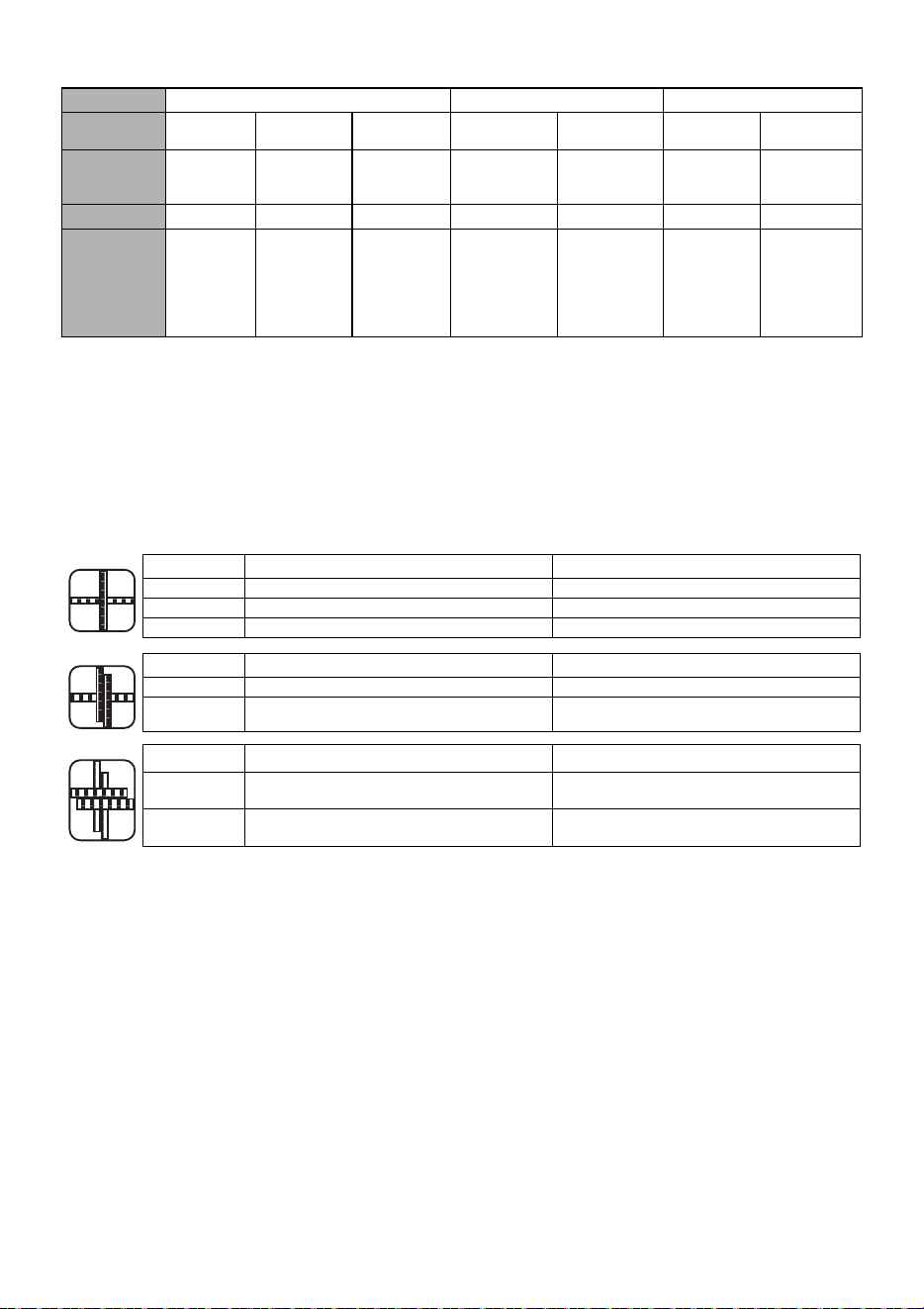
38
8. ESPECIFICACIONES DEL ALAMBRE
* Las RB398S/RB518/RB218 no son compatibles con la serie TW1061T ni con la serie TW1525.
9. APLICACIONES
• Paneles de hormigón prefabricado
• Cimientos de edificios
• Edificios comerciales
• Carreteras y puentes
• Tuberías de calefacción por suelo radiante
10. TAMAÑO DE ARMADURA APLICABLE
MODELO
RB398S RB518 RB218
ALAMBRE DE
AMARRE
TW898 TW898-PC TW898-EG TW898 TW898-PC TW898 TW898-EG
TIPO DE
ALAMBRE
Alambre
recocido
Alambre
bañado en
poliéster
Alambre
electrogalvanizado
Alambre recocido Alambre bañado
en poliéster
Alambre
recocido
Alambre
electrogalvanizado
DIÁMETRO
21 GA (0.8 mm) 21 GA (0.8 mm) 21 GA (0.8 mm) 21 GA (0.8 mm) 21 GA (0.8 mm) 21 GA (0.8 mm) 21 GA (0.8 mm)
AMARRES POR
BOBINA
Aprox.
120 amarres
Aprox.
105 amarres
Aprox.
110 amarres
(3 abrazaderas/
amarres)
Aprox. 90 amarres
(4 abrazaderas/
amarres)
Aprox. 75 amarres
(3 abrazaderas/
amarres)
Aprox. 80 amarres
(4 abrazaderas/
amarres)
Aprox. 65 amarres
Aprox.
170-210 amarres
Aprox.
155-190 amarres
Mínimo Máximo
RB398S #3 × #3 (10 mm × 10 mm) #5 × #6 (16 mm × 19 mm)
RB518 #5 × #5 (16 mm × 16 mm) #7 × #8 (22 mm × 25 mm)
RB218 Malla × Malla #3 × #3 (10 mm × 10 mm)
Mínimo Máximo
RB398S #3 × #3 × #3 (10 mm × 10 mm × 10 mm) #4 × #4 × #4 (13 mm × 13 mm × 13 mm)
RB518 #4 × #4 × #3 (13 mm × 13 mm × 10 mm) #5 × #5 × #8 (16 mm × 16 mm × 25 mm)
Mínimo Máximo
RB398S
#3 × #3 × #3 × #3
(10 mm × 10 mm × 10 mm × 10 mm)
#4 × #4 × #4 × #4
(13 mm × 13 mm × 13 mm × 13 mm)
RB518
#3 × #3 × #3 × #3
(10 mm × 10 mm × 10 mm × 10 mm)
#4 × #4 × #5 × #5
(13 mm × 13 mm × 16 mm × 16 mm)
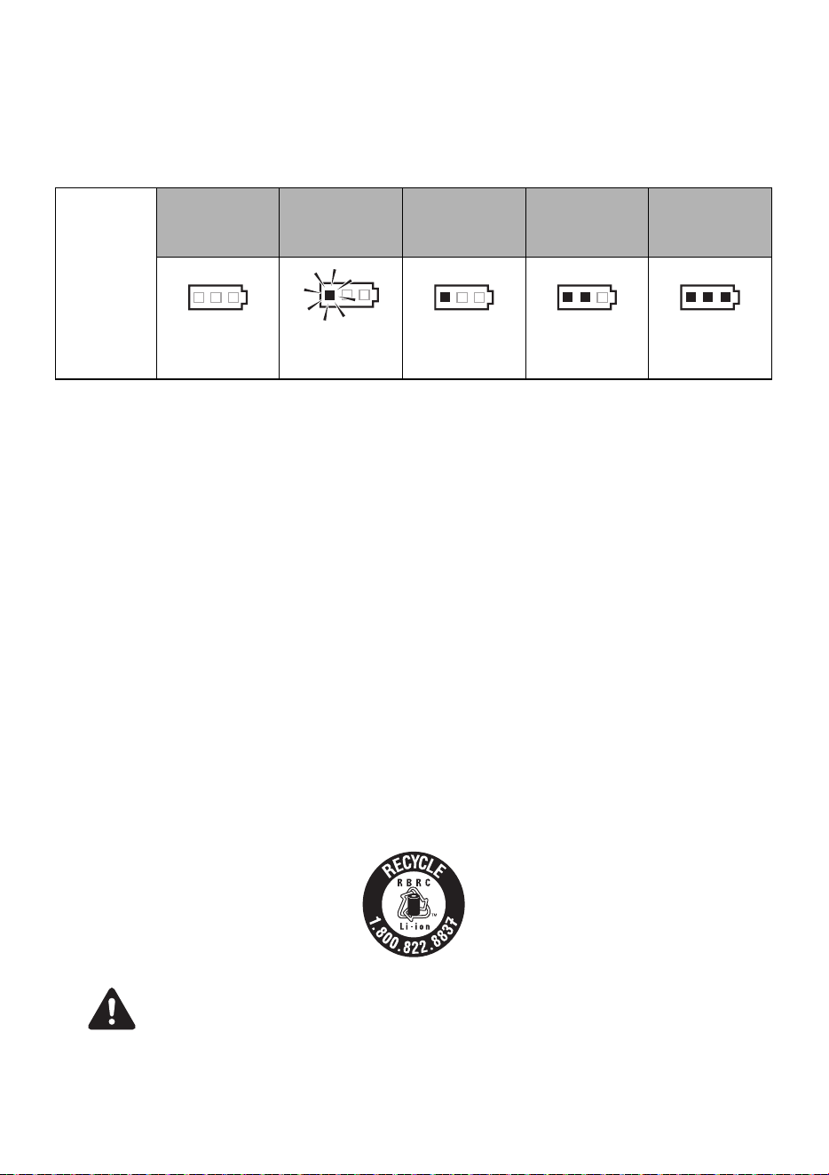
39
11. INSTRUCCIONES DE LA BATERÍA
Acerca del indicador de nivel de la batería
(1) Para comprobar el nivel de la batería (excepto mientras está cargando o si se está
manipulando la herramienta de carga), pulse el botón de comprobación de nivel de
la batería (Fig.47.I).
(2) El indicador de nivel de la batería (Fig.47.J) se ilumina según el nivel de la batería.
Vida útil del paquete de baterías
Si se observa alguna de las situaciones que se describen a continuación, el paquete de baterías ha
llegado al final de su vida útil. Cámbielo por uno nuevo.
Aunque el paquete de baterías se haya cargado correctamente (totalmente cargado), se observa una
importante reducción del tiempo de amarre.
•
Cuando esto suceda, no cargue el paquete de baterías. Si la velocidad de rotación del motor se
desacelera, se considera que la energía del paquete de baterías está a punto de agotarse. Si se sigue
utilizando la herramienta, se ocasionará una descarga excesiva, lo que podría acortar la vida útil del
paquete de baterías y ocasionar problemas de funcionamiento del cuerpo principal de la herramienta.
• No use un paquete de baterías caducado.
•
Si lo hace, el cuerpo principal del aparato sufriría problemas de funcionamiento. Cargar un paquete
de baterías caducado también provocaría problemas de funcionamiento en el cargador de baterías.
•
No arroje las baterías o paquetes de baterías al fuego ni al agua. Las baterías o paquetes de
baterías deben recogerse, reciclarse o eliminarse de una manera que no afecte al medioambiente.
•
Proteja la batería frente el calor, la radiación solar continua y el fuego. Existe peligro de explosión.
• Cargue el paquete de baterías en un rango de temperatura de entre 41 °F (5 °C) y 104 °F (40 °C).
Reciclado de una batería de ion litio
El producto que ha adquirido funciona con una batería de ion litio que es reciclable. Cuando llegue al final de su vida útil, y según
la normativa estatal y local, es ilegal eliminar la batería en el sistema ordinario de residuos municipales. Llame al 1-800-8-
BATTERY para obtener información sobre cómo reciclar la batería.
El paquete de baterías MAX utiliza una batería de ion litio; puede ser ilegal eliminar esta batería en el sistema de residuos
municipales. Consulte las disposiciones vigentes en su zona para el reciclado y la eliminación correcta de este tipo de producto.
Cuando proceda a eliminar el paquete de baterías, asegúrese de poner la tapa del paquete en el
terminal (asegurada con cinta aislante) para evitar cortocircuitos.
Indicador de
nivel de la
batería
Nivel de la
batería:
0%
Nivel de la
batería:
aprox. entre el
0 y el 10%
Nivel de la
batería:
aprox. entre el
10 y el 40%
Nivel de la
batería:
aprox. entre el
40 y el 70%
Nivel de la
batería:
aprox. entre el
70 y el 100%
Todos los
indicadores
APAGADOS
Un indicador
rojo
intermitente
Un
indicador rojo
encendido
Dos indicadores
rojos
encendidos
Tres indicadores
rojos
encendidos
AVISO
PRECAUCIÓN

40
12. INSTRUCCIONES DE FUNCIONAMIENTO
1. Cómo instalar el alambre de amarre
• Coloque el interruptor principal (Fig.6.7) en la posición
"OFF" ("desconectado"), coloque el seguro del
disparador (Fig.6.8) en la posición "LOCK"
("bloqueado") y extraiga el paquete de baterías (Fig.6.0)
cuando cambie el paquete de baterías, sustituya o ajuste
el alambre de amarre, se produzca cualquier anomalía o la
herramienta esté fuera de uso
1-1 (Fig.9) Presione la palanca de liberación (Fig.9.3) de este
equipo y confirme que dicha palanca queda asegurada en
el bloqueo (Fig.9.2).
1-2 (Fig. 10) Despegue aproximadamente 5 cm (2") de la cinta
que fija el alambre de amarre. Tire de la punta del alambre
de amarre expuesto.
Asegúrese de usar únicamente el alambre de amarre
especificado (serie TW898 de MAX).
El uso de un alambre de amarre que no sea el especificado
puede provocar averías en el equipo. Por lo tanto, asegúrese de
usar únicamente la TW898 de MAX especificada. No utilice un
cable de amarre que se haya oxidado, ya que su uso provocaría
una avería en el equipo.
* No se pueden usar bobinas de alambre antiguas TW897A.
1-3 (Fig. 11) Presione el tope de bobina (Fig. 11.d) para liberar
el portabobinas (Fig.11.f).
1-4 (Fig.12) Disponga el alambre de amarre (Fig.12.c) en la
herramienta haciendo coincidir el lado del alambre de
amarre como muestra la imagen. A continuación, presione
el portabobinas (Fig.12.f) y fíjelo deslizando el tope de
bobina.
1-5 (Fig.13) Introduzca la punta del alambre de amarre estirado
en la guía del alambre (Fig.13.m). A continuación,
colóquelo en el tubo (Fig.13.n).
1-6 Disponga alrededor de 4" (10 cm) de cable dentro del tubo.
1-7 La punta del alambre de amarre debe enderezarse para
permitir que pase a través del mecanismo de alimentación
de alambre. Si la punta del cable está doblada, al montar el
alambre de amarre, el cable podría atascarse en el interior
de la máquina.
(Fig.14) Si el visor está sucio y no se puede confirmar
la posición del tubo
Abra el visor y elimine la suciedad de su interior con un paño
suave, etc. Cierre nuevamente el visor tras su limpieza para
asegurarse de que no puedan entrar objetos extraños en la
máquina.
1-8 (Fig.14) Libere el bloqueo (Fig.14.2) y confirme que la
palanca de liberación (Fig.14.3) haya regresado a su
posición original y que los engranajes de alimentación
(Fig.14.l) estén sujetando el alambre de amarre
(Fig.14.c). Esto completa la operación de montaje del
alambre de amarre.
1-9 Retire la cinta del alambre de amarre en su totalidad.
1-10 (Fig. 15) Elimine la holgura de la bobina de alambre.
Asegúrese de que el alambre de amarre no quede atrapado
detrás de la bobina. Esto podría provocar un atasco.
• (Fig.16) Cuando coloque el interruptor principal en la
posición "ON" ("CONECTADO"), nunca acerque la mano
a las piezas de amarre o giratorias del extremo de la
herramienta.
• No toque el alambre de amarre durante el trabajo de
amarre (mientras la herramienta está en funcionamiento).
•
No encienda y apague el interruptor principal en sucesión
rápida, ya que esta operación provocará averías en la máquina.
1-11 (Fig.17) Introduzca el paquete de baterías en el cuerpo
principal de la herramienta hasta oír un clic. Disponga el
interruptor principal en Encendido.
1-12 (RB518, RB218) (Fig.37) La herramienta alimenta unos
6" (150 mm) de cable y lo corta automáticamente. Retire
el extremo cortado del cable con unos alicates.
1-13 (Fig.18) Disponga el seguro del disparador (Fig.18.
8
) en la
posición de DESBLOQUEAR antes de usar la herramienta.
2. Cómo extraer el alambre de amarre
•
(Fig.6) Coloque el interruptor principal (Fig.6.
7
) en la
posición "OFF" ("DESCONECTADO"), coloque el seguro del
disparador (Fig.6.
8
) en la posición "LOCK"
("BLOQUEADO") y extraiga el paquete de baterías (Fig.6.
0
).
2-1 (Fig.9) Presione la palanca de liberación (Fig.9.3) y
confirme que queda asegurada en el bloqueo (Fig.9.2).
2-2 (Fig.19) Retire el alambre de amarre (Fig.19.c) de la guía
del alambre (Fig.19.m).
2-3 (Fig.12) Deslice el tope de la bobina (Fig.12.d) para liberar
el portabobinas (Fig.12.f) y retire el alambre de amarre
(Fig.12.c)
2-4 Monte el nuevo alambre de amarre. (Consulte la
explicación del método de montaje del alambre de amarre).
3. Cuando el alambre de amarre se queda
sin cable de enlace
Deben quedar alrededor de 12" (300 mm) del alambre de amarre
al final de la bobina. Esta longitud debe descargarse con la
bobina antigua y sustituirse por una nueva.
4. (RB398S) Ajuste de tensión
(Fig.20) Este disco selector (Fig.20.5) le permite ajustar
ligeramente el par de tensión del alambre. Para aumentar la
tensión, gírelo hacia la izquierda. Para disminuir la tensión, gírelo
hacia la derecha.
4. (RB518) Ajuste de tensión y envoltura
(Fig. 38) El disco selector de par y envoltura (Fig. 38.5) le
permite configurar 3 envolturas/amarres o 4 envolturas/amarres,
además de ajustar el par.
Para aumentar la tensión, gírelo hacia la izquierda.
Para disminuir la tensión, gírelo hacia la derecha.
4. (RB218) Ajuste de longitud del cable
(Fig. 40) El disco selector de alimentación (Fig. 39.5) es un
mecanismo pensado para ajustar la velocidad de alimentación
del alambre de amarre. Cuando la longitud del borde (Fig.40.x)
no sea adecuada tras el enlace, use este disco selector para
ajustarla.
5. Función de desconexión automática
Esta herramienta tiene una función de "Desconexión automática"
que ahorra consumo de energía de la batería de iones de litio
cuando la herramienta no está en funcionamiento. Si la
herramienta está sin funcionar durante 30 minutos, se desconecta
automáticamente. Este es el "apagado automático". Cuando el
suministro eléctrico se interrumpa automáticamente, coloque el
interruptor principal en posición "OFF" ("DESCONECTADO") y
luego vuelva a colocarlo en posición "ON" ("CONECTADO") para
poner en funcionamiento la herramienta.
6. Cómo utilizar RB398S/RB518/RB218
Coloque el interruptor principal (Fig.6.7) en la posición
"OFF" ("desconectado"), el seguro del disparador (Fig.6.8)
en la posición "LOCK" ("bloqueado") y extraiga el paquete
de baterías (Fig.6.0).
6-1 (Fig.17) Introduzca el paquete de baterías en el cuerpo
principal de la herramienta hasta oír un clic.
6-2 Cuando se coloca el interruptor principal (7) en la posición
"ON" ("conectado"), el gancho de la punta gira
automáticamente; tenga mucho cuidado de no colocar los
dedos cerca de ninguna pieza móvil o giratoria. Coloque el
ADVERTENCIA
AVISO
ADVERTENCIA
AVISO
41
interruptor principal en la posición "ON" ("conectado") y el
seguro del disparador (8) en la posición "UNLOCK"
("desbloquear").
6-3 (Fig.22) Incline la herramienta en un ángulo de 45°
respecto de las armaduras entrecruzadas.
6-4 (Fig.23) Coloque la herramienta perpendicularmente a la
superficie de las armaduras entrecruzadas.
6-5 Una vez accione el disparador, la herramienta completa
automáticamente una serie de acciones de amarre
(alimentación, corte, sujeción y amarre).
Durante el funcionamiento de la herramienta
• No mueva la herramienta durante la operación de amarre
hasta que deje de funcionar automáticamente.
6-6 (Fig.24) Amarre en dirección alterna.
6-7 (Fig.25) Amarre entrecruzado.
Antes de realizar el segundo amarre, doble el extremo del primero.
6-8 (Fig.26) Cuando necesite un ajuste adicional, disponga
armaduras (Fig.26.a) en la parte superior de la pieza del
brazo (Fig.26.1).
13. MANTENIMIENTO
1-1 Inspeccionar regularmente la herramienta
Para conservar el rendimiento, limpie e inspeccione
periódicamente la herramienta.
1-2 No lubrique el equipo
No lubrique este equipo bajo ninguna circunstancia. La
aplicación de lubricación eliminaría la grasa del interior de
la herramienta y ocasionaría problemas en la herramienta.
1-3 (Fig.27) Limpie regularmente el mecanismo de alimentación.
Para conservar el rendimiento de la herramienta, limpie
periódicamente el mecanismo alrededor del engranaje de
alimentación. Con ayuda de un soplete de aire o similar, elimine el
polvo y los restos de hierro alrededor del engranaje de alimentación.
1-4 Limpie la herramienta con un paño seco suave.
No utilice un paño húmedo o sustancias volátiles, como
diluyentes o bencina.
14. MANUAL DE LIMPIEZA
Cuando la máquina funciona durante largas horas, el polvo y las virutas
de alambre pueden adherirse a la sección de corte. En tal caso,
desmonte y limpie la máquina de acuerdo con el siguiente procedimiento.
(Si un cable queda atrapado en la sección de la cortadora en la guía A,
puede retirar el cable de acuerdo con el mismo procedimiento).
(RB398S)
Desmontaje
• No extraiga los 2 pernos sin revestimiento.
1-1 Afloje los 2 pernos de cabeza hueca hexagonal (plateados)
M3 × 6 (Fig.28.o)
1-2 Desmonte el brazo B (Fig.29.t) y los 2 pernos de cabeza
hueca hexagonal (plateados) M3 × 6 (Fig.29.o).
1-3 Desmonte la cortadora (Fig.30.p) y la cortadora fija
(Fig.30.r), y límpielas. (Las piezas extraíbles son la
cortadora (Fig.30.p), la cortadora fija (Fig.30.r), la guía
del cable A (Fig.30.q) y la unidad de placa fresadora
(Fig.30.s)).
Ensamblado
• (Fig.31) Monte la cortadora fija (Fig.31.r) de forma que el
orificio grande (Fig.31.b) se sitúe en la parte trasera y el
orificio pequeño (orificio grande) (Fig.31.c) en el lado
superior.
1-4 Coloque el pasador de la unidad de placa fresadora
(Fig.31.s) a través del orificio de la biela de conexión de la
cortadora (Fig.31.u) y monte la cortadora fija (Fig.31.r)
en la unidad.
1-5 Instale la cortadora (Fig.32.p) y monte la guía del cable A
(Fig.32.q).
1-6 Alinee la ranura (Fig.33.v) de la guía del cable B
(Fig.33.w) unida al brazo B (Fig.33.t) con el tubo
(Fig.34.n), y monte el brazo B.
1-7 (Fig.35) Asegúrese de que el brazo B esté bien montado y
apriete los 2 pernos de cabeza hueca hexagonal
(plateados) M3 × 6. (Fig.35.o) (par de apriete:
15,5 lib.pie·pulg. (175 cN·m)).
• (Fig.36) ¿Hay piezas sueltas?
Asegúrese de que las piezas exteriores estén alineadas y que estén
ensambladas de forma segura, sin ningún espacio entre ellas.
(RB518) (RB218)
Desmontaje
1-1 (Fig.41) Afloje los 2 pernos de cabeza hueca hexagonal
(plateados) M3 × 5 (Fig.41.y).
1-2 (Fig. 42) Retire el brazo B (Fig. 42z) y los 2 pernos de
cabeza hueca hexagonal (plateados) M3 × 5 (Fig. 42.y).
1-3 (Fig.43) Desmonte la cortadora (Fig.43.
D
) y la cortadora fija
(Fig.43.
C
), y límpielas. (Las piezas extraíbles son la
cortadora, la cortadora fija y el pasador de paso (Fig.43.
B
)).
Ensamblado
• (Fig.44) Monte la cortadora fija (Fig.44.C) de forma que el
orificio grande (Fig.44.G) se sitúe en la parte trasera y el
orificio pequeño (Fig.43.H) en el lado superior.
1-4 (Fig.45) Introduzca el pasador de paso (Fig.45.B) en el
orificio y luego en el orificio de la varilla de conexión
(Fig.43.F). Asegúrese de que el pasador de paso esté
completamente introducido.
1-5 (Fig.46) Asegúrese de que el brazo B (Fig.41.z) esté bien
montado y apriete los 2 pernos de cabeza hueca hexagonal
(plateados) M3 × 5 (Fig.46.y). (Par de apriete:
15,5 lib.pie·pulg. (175 cN·m)).
•
El tornillo (derecho) (Fig.46.
y
) debe tener la arandela
(Fig.46.
E
). Monte primero la arandela y luego apriete el perno.
15. ALMACENAMIENTO
No guarde la herramienta en lugares fríos. Manténgala en un lugar
templado. Cuando no la utilice, guarde la herramienta en un lugar
templado y seco. Manténgala fuera del alcance de los niños. Con el
tiempo, todas las herramientas de calidad requerirán servicio o
sustitución de piezas debido al desgaste provocado por el uso normal.
(Fig.21) Desmonte la bobina de alambre de amarre
Cuando se haya terminado el alambre de amarre, retírelo de la herramienta.
Almacenamiento de la herramienta
Cuando haya finalizado los trabajos de amarre o cuando no piense
utilizar la herramienta durante un tiempo, apáguela, asegúrese de
que el motor se haya detenido, bloquee el disparador y retire el
paquete de baterías. La herramienta, las fijaciones y los accesorios
deben guardarse en un lugar seco y bien ventilado en el que la
temperatura no supere los 104 °F (40 °C). El paquete de baterías,
con una tapa montada en la terminal del paquete para evitar
cortocircuitos, debe almacenarse en un lugar seco y bien ventilado
donde la temperatura no supere los 86 °F (30 °C).
AVISO
AVISO
Parte trasera Lado superior
AVISO
AVISO
Parte trasera Lado superior
AVISO

42
16. SOLUCIÓN DE PROBLEMAS/REPARACIONES
La resolución de problemas y/o las reparaciones las realizarán únicamente los distribuidores autorizados de MAX CO., LTD. u otros
especialistas.
Esta herramienta le alerta de las siguientes condiciones mediante un sonido y una lámpara de advertencia. La luz de advertencia se
ilumina o parpadea, y está interbloqueada con el sonido de advertencia. Adopte una contramedida de acuerdo con la siguiente tabla.
• Ante cualquiera de las siguientes condiciones, asegúrese de poner el interruptor principal (Fig.1.7) en OFF antes de iniciar
las contramedidas.
• Al colocar el interruptor principal en ON, no toque la pieza de amarre de la pieza giratoria en la punta de la herramienta.
Si el problema no se resuelve al aplicar las siguientes contramedidas, asegúrese de poner el interruptor principal en
APAGADO y de contactar con el distribuidor donde adquirió el equipo o con distribuidores autorizados de MAX CO., LTD.
N. ° Operación normal Problema
Sonido de
advertencia
Causa Qué comprobar Solución
1. Suministro eléctrico
ON → El eje de
extremidad se inicia
y la cortadora de
alambre funciona
automáticamente.
No tiene lugar
ninguna
operación.
No se emite
sonido.
Batería agotada
(completamente
vacía)
Confirme que la batería
está cargada.
Realice la carga normal.
La placa de
electrodos se ha
oxidado.
Sacando la batería,
compruebe si el
electrodo se ha oxidado.
Pula la parte terminal de
la batería con un paño
seco, etc.
Un pitido largo
(Piii...)
La guía de curvado
(Fig.1.b) se deja
abierta.
Abrir/cerrar la guía de
curvado
Cierre completamente la
guía de curvado.
Pitidos cortos
continuos
(Pi, pi, pi, ...)
El cable de enlace se
ha enredado
alrededor de la
sección de giro.
Apague la alimentación y
saque la batería para
confirmar si el cable de
enlace se ha enredado
dentro de la guía de
curvado.
Apague la alimentación,
retire el cable de enlace
dentro de la guía de
curvado.
Dos pitidos cortos
repetidos durante
10 segundos
(Pipi, Pipi, ...), que
después se
apagan
automáticamente
La batería está
vacía.
Confirme que la batería
está cargada.
Realice la carga normal.
El paquete de
baterías se introduce
cuando el interruptor
principal está en ON.
Asegúrese de introducir
la batería solo cuando el
interruptor principal esté
apagado.
Ponga el interruptor
principal en OFF, luego
en ON.
2. Alimentación
eléctrica On → La
lámpara LED está
iluminada. → No
funciona durante
más de 30 minutos
→ La lámpara LED
se apaga. →
Aunque se acciona
el disparador, no se
inicia ninguna
operación.
No se inicia
ninguna
operación,
aunque se
acciona el
disparador.
No se emite
sonido
Operación normal. Ponga el interruptor
principal en OFF, luego
en ON.
Ponga el interruptor
principal en OFF, luego
en ON.
3. Disparador
activado → Salida
de alambre.
No se realiza
ningún envío de
alambre.
Un pitido largo
(Piii...)
La guía de curvado
se deja abierta.
Abrir/cerrar la guía de
curvado
Cierre completamente la
guía de curvado.
Tres pitidos
cortos
repetidos
(Pipipi,
pipipi, ...)
El alambre de
amarre se ha
agotado.
Compruebe si el alambre
de amarre se ha agotado
o no.
Colocar el nuevo
alambre de amarre.
Alambre atrapado
dentro de la bobina.
Verifique si el cable
dentro de la bobina se ha
aflojado y quedado
atrapado.
Retire cualquier resto
presente en la bobina.
La sección de la
cortadora (Fig. 29)
está bloqueada por
una sustancia
extraña.
Confirmar el
funcionamiento de la
sección de la cortadora.
Limpie la sección de la
cortadora con un paño
seco o con aire
comprimido.
Hay un cable
atrapado en la
sección de la
cortadora o en la
guía A (Fig.29.q).
Compruebe si hay algún
cable atrapado.
Desmonte la sección de
la cortadora y retire el
cable atrapado.
(Fig.28~36)
Cinco pitidos
cortos
(Pipipipipi,
pipipipipi)
El motor se ha
calentado.
El sonido de advertencia
no se emite de forma
continua. Ocurre solo
cuando se tira del
disparador.
Detener la máquina y
permitir que se enfríe.
ADVERTENCIA

43
3. Disparador
activado → Salida
de alambre.
El envío del
cable se
detiene a mitad
de camino.
Cuatro pitidos
cortos
repetidos
(Pipipipi,
pipipipi, ...)
El alambre de
amarre no está
configurado en la
herramienta.
Compruebe si el alambre
de amarre se ha
configurado en la
herramienta.
Disponer el alambre de
amarre.
Se ha utilizado un
alambre de enlace
de un tipo no
designado.
Confirmar la cara lateral
de la bobina.
Utilice alambre de
amarre TW898 de MAX.
Tres pitidos
cortos
repetidos
(Pipipi,
pipipi, ...)
El cable de enlace se
ha enredado dentro
de la bobina.
Confirmar el enrollado de
la bobina
Retire cualquier resto
presente en la bobina.
4. El cable de enlace
realiza un círculo.
El curvado está
desordenado y
sale de la guía
de curvado.
No se emite
sonido.
El alambre, al
golpear las barras de
refuerzo, ha
resultado repelido.
Compruebe si el cable
golpea las barras de
refuerzo en el enlace.
Preste atención para
que el cable no golpee
las barras de refuerzo en
el enlace.
5. El alambre está
sujeto a cortes.
No se realiza
ningún corte de
alambre.
Pitidos cortos
continuos.
(Pipipipipipi...)
La sección de la
cortadora está
bloqueada por una
sustancia extraña.
Confirmar la función de la
sección de la cortadora.
Limpie la sección de la
cortadora con un paño
seco o con aire
comprimido.
6. El alambra se
retuerce.
El alambre se
enreda.
No se emite
sonido.
El alambre, al
golpear las barras de
refuerzo, resultó
repelido.
Compruebe si el cable
golpea las barras de
refuerzo en el enlace.
Preste atención para
que el cable no golpee
las barras de refuerzo en
el enlace.
Un pitido corto
y un pitido
largo,
repetidamente.
(Pipipipipipi...)
El cable de enlace se
ha enredado
alrededor de la
sección de giro.
Apague la alimentación y
saque la batería para
confirmar si el cable de
enlace se ha enredado
dentro de la guía de
curvado.
Apague la alimentación,
retire el cable de enlace
dentro de la guía de
curvado.
El poder de
enlace es débil.
No se emite
sonido.
Las barras de
refuerzo no son del
tamaño designado.
Confirmar el tamaño de
las barras de refuerzo a
enlazar.
(VÉASE LA PÁGINA 38)
Utilice el alcance de
diámetro apropiado.
Manipulación
errónea, como la
aplicación incorrecta
de la máquina.
Confirme cómo aplicar la
máquina a las barras de
refuerzo.
Girando el selector de
par (Fig.1.5) en + e
introduciéndolo en
dirección vertical, usar
una inclinación de 45°.
(Fig.22)
Función del
interruptor de la guía
de curvado
Compruebe si la guía de
curvado se deja abierta
en el enlace.
No opere la máquina
hasta que se complete el
enlace.
Se produce
torsión.
No se emite
sonido.
Las barras de
refuerzo no son del
tamaño designado.
Confirmar el tamaño de
las barras de refuerzo en
el enlace.
(VÉASE LA PÁGINA 38)
Utilice el alcance de
diámetro apropiado.
Manipulación
errónea, como la
aplicación incorrecta
de la máquina.
Confirme cómo aplicar la
máquina a las barras de
refuerzo.
Girando el selector de
par en - (menos) e
introduciéndolo en
dirección vertical, usar
una inclinación de 45°.
(Fig.22)
Funciona
adecuadamente
Dos pitidos
cortos.
(Pipi)
El paquete de
baterías mantiene la
baja potencia.
Confirme que la batería
esté completamente
cargada.
Realice la carga normal
después de que la
velocidad de amarre se
ralentice
considerablemente.
La herramienta se
utiliza a baja
temperatura.
Compruebe la
temperatura en el lugar
de trabajo.
Deje la herramienta y el
paquete de baterías a
una temperatura normal
en la sala durante un
tiempo y luego continúe
con la operación.
N. ° Operación normal Problema
Sonido de
advertencia
Causa Qué comprobar Solución
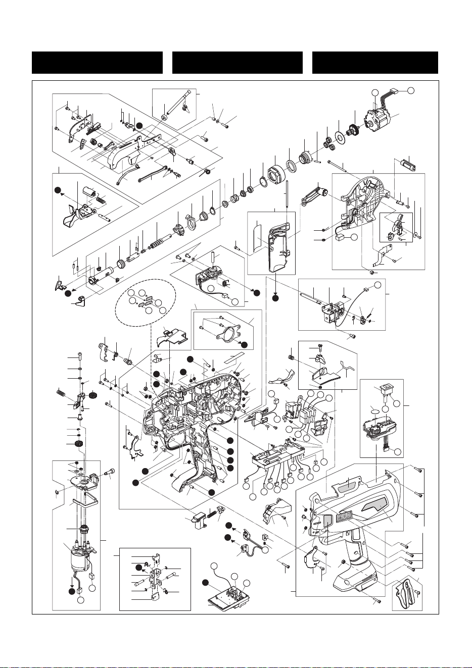
44
RB398S
EXPLODED
VIEW AND SPARE PARTS LIST
SCHEMA ECLATE ET LISTE DES
PIECES DE RECHANGE
DESPIECE DE LA MAQUINA Y
LISTA DE RECAMBIOS
BB
I
3
4
5
6
7
8
9
13
12
14
15
16
17
18
19
21
10
60
22
24
26
27
28
29
30
31
32
33
33
34
35
35
36
37
38
39
40
41
42
43
44
45
46
48
47
47
49
51
52
53
54
55
56
57
58
59
63
64
66
66
69
70
68
72
73
75
76
74
88
78
80
82
83
85
89
84
86
87
174
109
91
92
93
94
98
96
106
104
26
105
107
95
115
128
129
131
133
134
135
136
137
130
144
103
61
103
103
103
141
142
66
142
149
143
148
154
153
155
147
142
103
103
116
117
118
26
123
121
122
94
125
126
160
163
120
165
166
167
169
171
142
173
B
C
C
D
G
E
F
E
F
G
J
J
b
c
w
e
g
k
s
k
n
e
m
99
108
D
r
v
94
99
100
156
161
162
159
A
142
66
66
142
8
n
p
d
d
b
h
s
u
a
a
c
w
x
x
i
i
t
j
f
j
t
p
103
103
103
u
f
h
v
g
r
150
151
144
144
120
144
144
145
176
110
111
111
113
113
112
94
94
114
K
II
A
K
H
H
1
2
11
20
62
23
65
67
71
65
65
77
90
97
102
103
124
132
127
138
62
79
146
62
146
62
62
152
152
65
152
140
67
103
103

45
RB398S
ITEM
NO.
PART
NO.
MATERIAL ENGLISH FRANÇAIS ESPAÑOL
1 BB40112 Steel BOLT 3X6 BOULON 3X6 PERNO 3X6
2 BB86701 Steel TORX BOLT 3X5 BOULON TORX 3X5 PERNO TORX 3X5
3 RB70404 Steel ARM B UNIT(397) UNITE DE BRAS “B”(397)
UNIDAD DE BRAZO “B”(397)
4 RB11999 Steel WIRE GUIDE B (397) GUIDE DE FIL “B” (397)
GUIA DE ALAMBRE “B” (397)
5 RB12000 Steel CUTTER COUTEAU CORTADORA
6 JJ10109 Steel E-RING 2 BAGUE 2 CF ANILLO EN E2 CF
7 RB12090 Steel CUTTER LEVER B (397) LEVIER DE COUTEAU “B” (397) PALANCA DE CORTADORA “B” (397)
8 JJ10514 Steel E-RING 3 CF BAGUE 3 CF ANILLO EN "E" 3 CF
9 RB12005 Steel CUTTER LEVER A (397) LEVIER DE COUTEAU “A” (397) PALANCA DE CORTADORA “A”(397)
10 FF51647 Steel HOLLOW PIN 1647 HOHLSTIFT 1647 GOUPILLE CREUSE 1647
11 RB12710 Steel SHAFT ARBRE ÁRBOL
12 RB12004 Steel CONNECTING ROD (397)
BIELLE DE CONNEXION (397)
BIELA (397)
13 RB12780 Steel PIN GOUPILLE PERNO
14 RB70794 Steel WIRE GUIDE A (397) GUIDE DE FIL “A” (397)
GUIA DE ALAMBRE “A” (397)
15 RB12121 Steel FIXED CUTTER (N) COUTEAU FIXE (N) CORTADORA FIJA (N)
16 RB70493 Steel CUTTER PLATE UNIT
UNITE DE PLAQUE DE COUTEAU
UNIDAD DE DISCO DE CORTE
17 RB12781 Stainless steel PLATE PLAQUE PLACA
18 RB81304 Steel ARM A UNIT UNITE DE BRAS “A” UNIDAD DE BRAZO “A”
19 RB11997 Stainless steel LEAF SPRING (397) RESSORT A FEU LLES SUPER EUR (397) MUELLE DE HOJAS SUPERIOR (397)
20 AA25113 Steel PAN-HEAD SCREW 2X4 VIS A TETE PLATE 2X4 TORNILLO DE CABEZA LLANA 2X4
21 RB70741
Steel,stainless steel
ARM ASSY(398S)
ENSEMBLE DE BRAS (398S)
CONJUNTO DEL BRAZO (398S)
22 KK33413 Steel SPRING 3413 RESSORT 3413 MUELLE 3413
23 BB40839 Steel SCREW 4X16 VIS 4X16 TORNILLO 4X16
24 RB12007 Rubber PIPE SPONGE EPONGE TUYAU ESPONJA DE TUBO
26 JJ10101 Steel E-RING 4 BAGUE 4 ANILLO EN E4
27 RB81136 Steel,rubber PIPE ASSY TUYAU ASSY TUBO ASSY
28 RB70565 Steel CURL GUIDE UNIT (399A) DE GUIDE DE BOUCLE UNIT (399A) DE GUÍA DE ONDULACIÓN UNIT (399A)
29 RB12010 Stainless steel CURL GUIDE COVER COUVERCLE DE GUIDE DE BOUCLE CUBIERTA DE GUÍA DE ONDULACIÓN
30 KK33365 Steel TORSION SPRING RESSORT DE TORSION MUELLE DE TORSIÓN
31 RB12110 Steel STOPPER SHAFT ARBRE DE RESSORT ÁRBOL DE MUELLE
32 RB70567
Steel,stainless
steel
CURL GUIDE ASSY (399A) ENSEMBLE DE GUIDE DE BOUCLE (399A) GRUPO DE GUÍA DE ONDULACIÓN (399A)
33 RB11816 Steel HOOK CROCHET GANCHO
34 RB81113 Steel WS PIN 2.5X10 GOUPILLE WS 2.5X10 PERNO WS 2.5X10
35 RB12014 Steel KEY CLAVETTE CHAVETA
36 RB12017 Steel SLEEVE A MANCHON “A” MANGUITO “A”
37 RB12279 Steel SLEEVE GUIDE GUIDE DE MANCHON GUÍA DE MANGUITO
38 RB70675 Steel TIP AXIS B AXE DE BOUT “B” EJE DE EXTREMIDAD “B”
39 FF31599 Steel PARALELL PIN 1599
GOUPILLE PARALLELE 1599
PERNO PARALELO 1599
40 KK23730 Steel COMP. SPRING 3730 RESSORT PRESS. 3730 MUELLE DE COMP. 3730
41 RB12708 Steel TIP AXIS A AXE DE BOUT “A” EJE DE EXTREMIDAD “A”
42 RB12785 Steel SLEEVE B MANCHON “B” MANGUITO “B”
43 RB12789 Steel CUTTER RING BAGUE DE COUTEAU ANILLO DE CORTADORA
44 RB12091 Steel CUTTER RING GUIDE GUIDE DE BAGUE DE COUTEAU GUÍA DE AN LLO DE CORTADORA
45 JJ21011 Steel C-RING 14 BAGUE EN “C” 14 ANILLO EN “C” 14
46 RB81314 Steel, PA TIP AXIS ASSY ENSEMBLE D’AXE DE BOUT GRUPO DE EJE DE EXTREMIDAD
47 RB12020 Steel SPRING COLLAR COLLIER A RESSORT COLLAR DE MUELLE
48 KK29026 Steel COMP. SPRING 9026 RESSORT PRESS. 9026 MUELLE DE COMP. 9026
49 RB12019 Urethan rubber BUMPER AMORTISSEUR AMORTIGUADOR
51 JJ21603 Steel C-RING 20 BAGUE EN C 20 ANILLO EN “C” 20
52 RB10338 PA INTERNAL GEAR ENGRENAGES INTERNE ENGRANAJES INTERNOS
53 RB12783 Steel RING BAGUE ANILLO
54 RB70745 Steel PLANET CAGE UNIT UNITÉ DE CAGE PLANÉTAIRE UNIDAD DE JAULA PLANETARIA
55 FF31589 Steel PIN 1589 GOUPILLE 1589 PERNO 1589
56 RB10341 Steel PLANET GEAR ENGRENAGE PLANETAIRE
ENGRANAJES PLANETARIOS
57 RB10484 Stainless steel GEAR PRESS WHEEL ROUE DE PRESSION D ENGRENAGES RUEDA DE PRESIÓN DE ENGRANAJES
58 RB70736 Steel SUN GEAR UNIT UNITE DE PIGNON SOLEIL UNIDAD CENTRAL DE ENGRANAJES
59 RB70734 TWISTING MOTOR MOTEUR DE TORSION MOTOR DE TORSIÓN
60 EE31131 Steel WASHER 1-3 RONDELLE 1-3 ARANDELA 1-3
61 FF51817 Steel HOLLOW PIN 1817 GOUPILLE CREUSE 1817 PERNO HUECO 1817
62 BB40810 Steel BOLT 3X16 BOULON 3X16 PERNO 3X16

46
63 RB70710 SENSOR CIRCUIT BOARD F UNIT PLAQUETTE DE CIRCUIT DE SENSEUR F PLACA DE CIRCUITO DE SENSOR “F”
64 RB81347
Steel,Stainless
steel
REEL GUIDE ASSY ENSEMBLE DE GUIDE DE BOBINE CONJUNTO DE GUÍA DE CARRETE
65 AA09501 Steel SCREW 3X6 CF VIS 3X6 CF TORNILLO 3X6 CF
66 FF51710 Steel HOLLOW PIN 1710 GOUPILLE CREUSE 1710 PERNO HUECO 1710
67 BB41706 Steel BOLT 4X10 CF BOULON 4X10 CF PERNO 4X10 CF
68 FF31563 Steel PIN 1563 GOUPILLE 1563 PERNO 1563
69 KK34089 Stainless steel SPRING 4089 RESSORT 4089 MUELLE 4089
70 RB70719
Steel, stainless
steel, PC, etc.
RATCHET COVER ASSY ENSEMBLE DE COUVERCLE DE RACHET GRUPO DE CUBIERTA DEL TRINQUETE
71 BB40720 Steel BOLT 3X12 BOULON 3X12 PERNO 3X12
72 RB12791 PET SPECIFICATION LABEL ÉTIQUETTE DES SPÉCIFICATIONS ETIQUETA DE ESPECIFICACIONES
73 RB70705 PET, PA MOTOR COVER ASSY (398S) ENSEMBLE COUVERCLE DE MOTEUR (398S) CONJUNTO DE CUBIERTA DE MOTOR (398S)
74 FF41871 Steel STEP PIN 1871 BOULON À GRADINS 1871 PERNO ESCALONADO 1871
75 KK34067 Stainless steel TORSION SPRING 4067 RESSORT DE TORSION 4067 MUELLE DE TORSION 4067
76 EE39609 Urethane rubber PLANE RUBBER WASHER 1.8X6X2 RONDELLE PLATE DE CAOUTCHOUC 1,8X6X2 ARANDELA DE CAUCHO 1,8X6X2
77 BB40714 Steel BOLT 3X50 BOULON 3X50 PERNO 3X50
78 RB12031 PA JOINT JOINT JUNTA
79 AA21419 Steel SCREW 3X8 CF VIS 3X8 CF TORNILLO 3X8 CF
80 RB81305
PA, stainless steel,
steel
REEL HOLDER ASSY ENSEMBLE DE PORTE-BOBINE GRUPO DE PORTA BOBINA
82 RB12038 Stainless steel REEL STOPPER SPRING RESSORT DE PIECE DE RETENUE DE BOBINE MUELLE DE RETÉN DE CARRETE
83 EE39184 Steel WASHER 3.1X11.8X1 RONDELLE 3,1X11,8X1 ARANDELA 3.1X11.8X1
84 RB12035 POM REEL STOPPER PIECE DE RETENUE DE BOBINE PIEZA DE RETENClÓN DE BOBINA
85 FF21240 Steel PIN 2.5X6 GOUPILLE 2.5X6 PERNO 2.5X6
86 RB12036 Stainless steel STOPPER PLATE PLAQUE DE PIéCE DE RETENUE PLACA DE PARTE DE RETENCIîN
87 RB70427
POM, steel,
stainless steel
REEL STOPPER ASSY ENSEMBLE DE TAQUET DE BOBINE CONJUNTO DE BLOQUE DE CARRETE
88 RB70770
PA, PC, POM, steel,
stainless steel, etc.
REEL MAGAZINE ASSY MAGASIN DE BOBINE ASSY ALOJAMIENTO DE BOBINA ASSY
89 RB12772 Steel PLATE B PLAQUE “B” PLACA “B”
90 BB41707 Steel BOLT 4X16 BOULON 4X16 PERNO 4X16
91 EE11103 Steel SPRING WASHER 2-4
RONDELLE DE RESSORT 2-4 ARANDELA DE MUELLE 2-4
92 EE39825 Steel WASHER 4.5X7.4X0.8 RONDELLE 4,5X7,4X0,8 ARANDELA 4,5X7,4X0,8
93 KK24175 Steel COMP. SPRING 4175 RESSORT PRESS. 4175 MUELLE DE COMP. 4175
94 JJ10113 Steel E-RING 2.5 BAGUE 2,5 ANILLO EN "E" 2,5
95 RB10359 Steel FEEDING GEAR B2 B2 DENGRENAGES DAVANCE B2 DE ENGRANAJES DE ALIMENTACIÓN
96 RB10362 Aluminum RELEASE LEVER
LEVIER DE DECLENCHEMENT
PALANCA DE DISPARO
97 FF41809 Steel STEP PIN 1809 BOULON À GRADINS 1809 PERNO ESCALONADO 1809
98 RB12852 Steel HOLLOW PIN GOUPILLE CREUSE PERNO DE ALAMBRE
99 EE32104 Stainless Steel WASHER 2-3 RONDELLE 2-3 ARANDELA 2-3
100 RB10357 Steel FEEDING GEAR B1 ENGRENAGES DAVANCE B1 B1 DE ENGRANAJES DE ALIMENTACIÓN
102 RB12766 Steel WIRE GUIDE C GUIDE DE FIL “C” GUÍA DE ALAMBRE “C”
103 CC41104 Steel HEX NUT 1-3 ÉCROU HEXAGONAL 1-3 TUERCA HEXAGONAL 1-3
104 RB12761 PA PARTITION PLATE PLAQUE DE DIVISION PLACA DE DIVISlÓN
105 RB12765 Rubber PARTITION SPONGE EPONGE DE DIVISION ESPONJA DE DIVISIÓN
106 EE31133 Steel WASHER RONDELLE ARANDELA
107 RB70509 Steel,PA FEEDING GEAR A ASSY ENSEMBLE “A” D ENGRENAGES DAVANCE
GRUPO “A” DE ENGRANAJES DE ALIMENTACIÓN
108 RB70729 FEEDING MOTOR ASSY MOTEUR DAVANCE ASSY MOTOR DE ALIMENTACIÓN ASSY
109 RB81312 Steel, PA, etc. FEEDING ASSY ENSEMBLE D’AVANCE CONJUNTO DE ALIMENTACIÓN
110 RB12773 Steel JAW A MACHOIRE “A” QUIJADA “A”
111 KK33420 Steel TORSION SPRING 3249
RESSORT DE TORSION 3249 MUELLE DE TORSIÓN 3249
112 RB12775 Steel JAW BASE BASE DE MACHOIRE BASE DE QUIJADA
113 FF41822 Steel STEP PIN 1822 BOULON À GRADINS 1821 PERNO ESCALONADO 1822
114 RB12774 Steel JAW B MACHOIRE “B” QUIJADA “B”
115 RB70739 Steel JAW BASE ASSY
BASE DE MACHOIRE ASSY
BASE DE QUIJADA ASSY
116 RB12769 Steel ROTARY PIN GOUPILLE ROTATIVE PASADOR GIRATORIO
117 RB81308 SOLENOID ASSY ENSEMBLE DE SOLENOIDE CONJUNTO DE SOLENOIDE
118 FF41876 Steel STEP PIN 1876 STUFENBOLZEN 1876 BOULON À GRADINS 1876
120 FF52119 Steel HOLLOW PIN 2119 GOUPILLE CREUSE 2119 PERNO DE ALAMBRE 2119
121 RB12029 Steel ROTARY PLATE PLAQUE ROTATIVE PLACA GIRATORIA
122 FF21620 Stainless steel PIN 2X12 GOUPILLE 2X12 PERNO 2X12
123 RB70771 Steel, etc. BRAKE ASSY ENSEMBLE DE FREIN CONJUNTO DE FRENO
124 BB40712 Steel BOLT 4X8 BOULON 4X8 PERNO 4X8
RB398S
ITEM
NO.
PART
NO.
MATERIAL ENGLISH FRANÇAIS ESPAÑOL

47
125 RB12770 Steel REEL PRESS PRESSE DE BOBINE PRENSA DE BOBINA
126 KK33373 Stainless steel SPRING 3373 RESSORT 3373 MUELLE 3373
127 AA22522 Steel SCREW 3X8 VIS 3X8 TORNILLO 3X8
128 ZS00034 MAIN SWITCH UNIT INTERRUPTEUR GÉNÉRAL INTERRUPTOR PRINCIPAL
129 RB12796 PET LABEL, TORQUE DIAL PLAQUE, CADRAN A COUPLE PLACA, CUADRANTE DE PAR
130 RB12814 PC HARNESS COVER CAPOT DU CÂBLAGE CUBIERTA DEL MAZO DE CABLES
131 RB70750
PC, POM, steel,
stainless steel, etc.
SWITCH BASE ASSY BASE DE COMMUTATEUR BASE DE CONMUTADOR
132 RB12054 Steel STEP PIN BOULON À GRADINS PERNO ESCALONADO
133 RB12053 POM RELEASE STOPPER PIECE DE RETENUE DE DECLENCHEMENT PIEZA DE RETENCIÓN DE DISPARO
134 RB12055 PC STOPPER BASE BASE DE RETENUE BASE DE RETENCIÒN
135 RB12056 Rubber SPONGE F EPONGE F ESPONJA F
136 RB81139
PC, POM, steel,
rubber
STOPPER BASE ASSY ENSEMBLE DE LA BASE DE RETENUE GRUPO DE LA BASE DEL RETÉN
137 KK29133 Steel COMPRESSION SPRING 9133 RESSORT À PRESSION 9133 MUELLE DE COMPRESIÓN 9133
138 BB40710 Steel BOLT 3X8 BOULON 3X8 PERNO 3X8
140 BB40709 Steel BOLT 3X16 BOULON 3X16 PERNO 3X16
141 RB12771 Steel PLATE A PLAQUE “A” PLACA “A”
142 CC42512 Steel HEX NUT 1A M4 CF
ÉCROU HEXAGONAL 1A M4 CF
TUERCA HEXAGONAL 1A M4 CF
143 RB12521 PET WARNING LABEL (398)
JOINT D’AVERTISSEMENT (398)
JUNTA DE ADVERTENCIA (398)
144 FF51714 Steel HOLLOW PIN 1714 GOUPILLE CREUSE 1714 PERNO HUECO 1714
145 RB12745 Stainless steel REEL PROTECTOR
PROTECTION DE LA BOBINE
PROTECTOR DE BOBINA
146 BB41503 Steel BOLT 3X8 BOULON 3X8 PERNO 3X8
147 RB11979 Steel COVER L (397) COUVERCLE “L” (397) CUBIERTA “L” (397)
148 RB81350 PA,PET, Steel, etc FRAME L ASSY(398S) ENSEMBLE DU CADRE L (398S) CONJUNTO DE ARMAZÓN IZQUIERDO (398S)
149 RB11987 PC WINDOW FENÊTRE VENTANILLA
150 RB12826 PC CONNECTOR BASE BASE DU CONNECTEUR BASE DEL CONECTOR
151 RB12827 PC CONNECTOR COVER CAPOT DU CONNECTEUR CUBIERTA DEL CONECTOR
152 AA05572 Steel SCREW 3X8 VIS 3X8 TORNILLO 3X8
153 RB12080 POM TRIGGER DÉCLENCHEUR DISPARADOR
154 KK23656 Steel COMPRESSION SPRING 3656 RESSORT À PRESSION 3656 MUELLE DE COMPRESIÓN 3656
155 RB12101 PC TRIGGER LOCK LEVER LEVIER DE BLOCAGE DE LA COMMANDE PALANCA DE SEGURO DE DISPARADOR
156 RB81349 SWITCH HARNESS UNIT CÂBLAGE DE L'INTERRUPTEUR CABLEADO DE INTERRUPTOR
159 RB12744 POM SWITCH BLOCK BLOC INTERRUPTEUR BLOQUE DE INTERRUPTOR
160 RB81390 MAIN CIRCUIT BOARD UNIT PLAQUETTE DE CIRCUIT PRINCIPALE PLACA DE CIRCUITO PRINCIPAL
161 KK23604 Steel COMPRESSION SPRING 3604 RESSORT À PRESSION 3604 MUELLE DE COMPRESIÓN 3604
162 RB12813 PC FRONT HARNESS COVER CAPOT AVANT DU CÂBLAGE CUBIERTA DEL MAZO DE CABLES DELANTERO
163 RB70697 PBT, copper ELECTRODE UNIT ÉLECTRODE ELECTRODO
165 RB11981 Steel COVER R (397) COUVERCLE “R” (397) CUBIERTA “R” (397)
166 RB12689 PET WARNING LABEL ÉTIQUETTE D'AVERTISSEMENT ETIQUETA DE ADVERTENCIA
167 RB11985 PET USAGE LABEL JOINT PR
PLACA DE INDICACIONES DE USO
169 RB12742 PET 398S LABEL ÉTIQUETTE 398S ETIQUETA DE 398S
171 RB70706 PA, PET, Steel, etc FRAME R ASSY(398S) ENSEMBLE DU CADRE R (398S) CONJUNTO DE ARMAZÓN DERECHO (398S)
173 RB81184 Steel BELT HOOK ASSY ENSEMBLE DU CROCHET DE COURROIE CONJUNTO DE GANCHO PARA CINTURÓN
174 RB12752 PC LED COVER COUVERCLE DE-DEL CUBIERTA DE LED
176 RB12661 ABS BRAND PLATE PLAQUE DE MARQUE PLACA DE MARCA
RB398S
ITEM
NO.
PART
NO.
MATERIAL ENGLISH FRANÇAIS ESPAÑOL
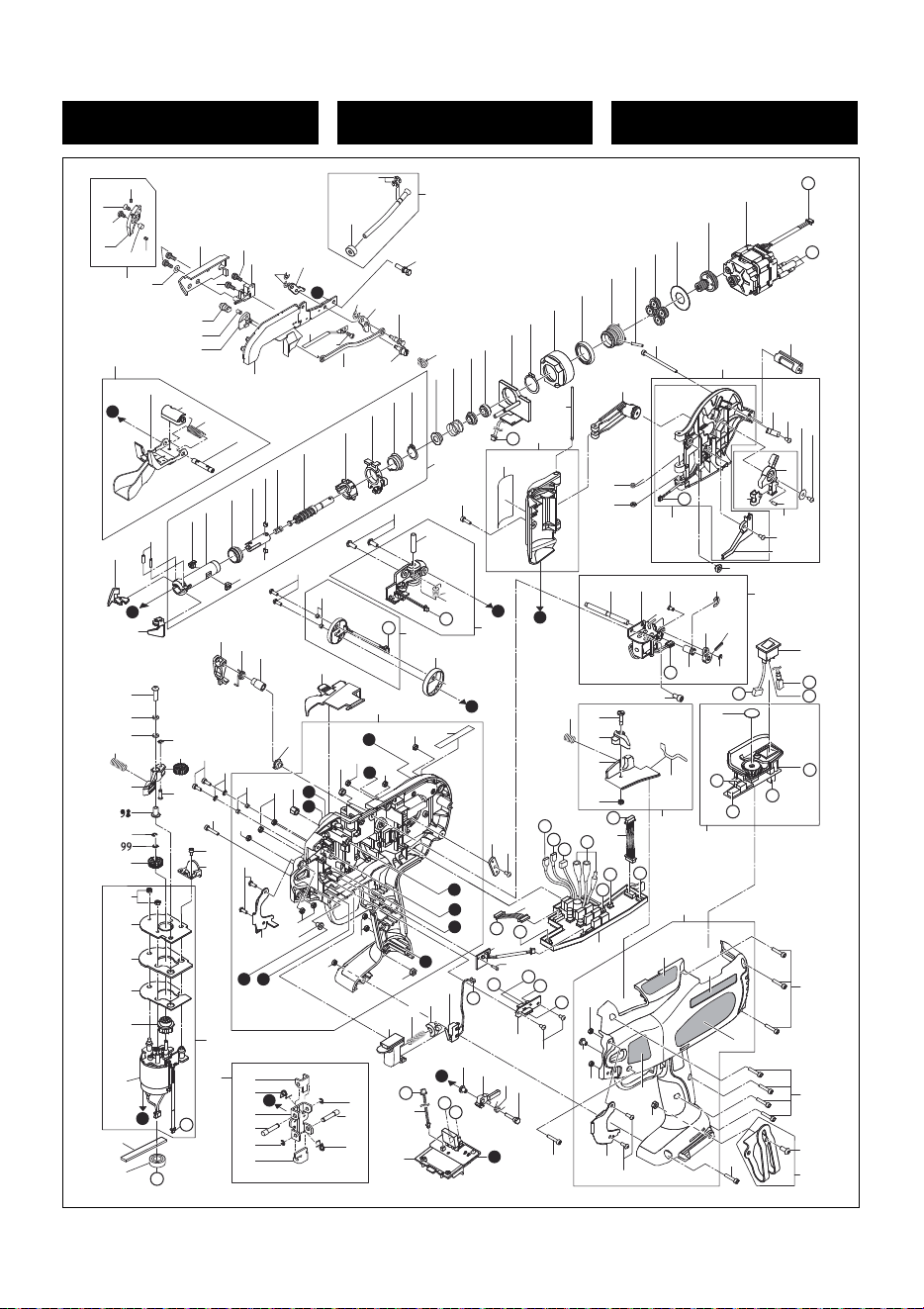
48
RB518
EXPLODED
VIEW AND SPARE PARTS LIST
SCHEMA ECLATE ET LISTE DES
PIECES DE RECHANGE
DESPIECE DE LA MAQUINA Y
LISTA DE RECAMBIOS
1
20
21
62
1
2
3
5
1
6
7
8
9
10
11
12
15
16
17
18
4
19
19
13
14
23
79
A
t
22
24
26
27
28
29
30
31
32
33
33
34
35
35
36
37
38
39
39
40
41
42
43
44
45
46
48
47
47
49
50
51
52
53
54
55
56
57
58
59
60
61
63
64
65
66
175
69
70
71
68
72
73
75
76
74
88
78
81
80
82
65
65
83
85
89
84
86
87
65
174
77
90
109
91
92
93
94
94
96
97
1
100
102
103
104
105
106
95
107
128
124
129
131
132
133
134
135
136
137
61
103
138
140
103
103
103
141
142
181
142
149
143
148
145
145
145
157
158
159
150
151
154
153
152
155
156
146
147
142
103
103
103
103
116
117
118
119
123
120
94
121
122
125
126
127
176
67
160
161
162
163
164
140
146
103
103
165
166
167
168
169
171
140
140
173
140
B
B
C
C
D
G
E
F
E
F
G
H
I
H
J
J
a
b
c
d
e
f
u
i
j
k
m
a
i
e
s
k
p
g
h
f
n
n
b
g
p
d
s
c
m
t
j
99
103
A
108
177
178
D
u
I
115
111
110
111
113
113
94
112
94
114
h

49
RB518
ESPAÑOLFRANÇAISENGLISHMATERIAL
ITEM
NO.
PART
NO.
1
2
3
4
5
6
7
8
9
10
11
12
13
14
15
16
17
18
19
20
21
22
23
24
25
26
27
28
29
30
31
32
33
34
35
36
37
38
39
40
41
42
43
44
45
46
47
48
49
50
51
52
53
54
55
56
57
58
59
BB40481
EE31122
RB12263
AA22005
RB11811
RB11798
RB12090
JJ10109
RB11815
FF44120
RB11818
RB81222
RB11800
AA25113
JJ10514
RB12228
RB12265
RB10392
AA71408
FF51667
RB11814
KK33370
RB12003
RB12007
JJ10101
RB81219
RB81224
RB12010
KK33365
RB12110
RB81217
RB11816
RB81113
RB12014
RB12280
RB12279
RB81242
RB10115
KK23730
RB12281
RB12785
RB70412
RB12091
JJ21011
RB81247
RB12020
KK29026
RB12019
RB81177
JJ21603
RB10338
LL11181
RB70681
FF31589
RB10341
RB10484
RB70418
RB70558
Steel
Steel
Steel
Steel
Steel
Steel
Steel
Steel
Steel
Steel
Steel
Steel
Stainless steel
Steel
Steel
Steel
Steel
Steel
Steel
Steel
Steel
Steel
Steel
Rubber
Steel
Steel,rubber
Steel
Stainless steel
Steel
Steel
Steel
Steel
Steel
Steel
Steel
Steel
Steel
Steel
Steel
Steel
Steel
Steel, PA
Steel
Steel
Steel, PA
Steel
Steel
Urethan rubber
Steel,PA,etc.
Steel
PA
Steel
Steel
Steel
Steel
Stainless steel
Steel
BOLT 3×5
WASHER 3×7
ARM B
SCREW M3×5
WIRE GUIDE A
WIRE GUIDE B
CUTTER LEVER B (397)
E-RING2
FIXED CUTTER
STEP PIN 4120
CUTTER
ARM A UNIT(517)
LEAF SPRING
PAN-HEAD SCREW 2×4
E-RING 3 CF
CUTTER LEVER A
CONNECTING ROD
PIN
SCREW M3×3
HOLLOW PIN 1667
WIRE GUIDE SCREW
TORSION SPRING 3370
SCREW
PIPE SPONGE
E-RING 4
PIPE ASSY(517)
CURL GUIDE UNIT (517)
CURL GUIDE COVER
TORSION SPRING
STOPPER SHAFT
CURL GUIDE ASSY (517)
HOOK
SPRING PIN 2.5×10
KEY
SLEEVE A
SLEEVE GUIDE
TIP AXIS B
KEY B
COMPRESSION SPRING 3730
TIP AXIS A
SLEEVE B
CUTTER RING UNIT
CUTTER RING GUIDE
C-RING 14
TIP AXIS ASSY
SPRING COLLAR
COMPRESSION SPRING 9026
BUMPER
TIP AXIS GUIDE ASSY 2
C-RING 20
INTERNAL GEAR
WHEEL 6704
PLANET CAGE UNIT(518)
PARALELL PIN 1589
PLANET GEAR
GEAR PRESS WHEEL
SUN GEAR UNIT
TWISTING MOTOR (RB517)
BOULON 3×5
RONDELLE 3×7
BRAS B
VIS M3×5
GUIDE DE FIL “A”
GUIDE DE FIL “B”
LEVIER DE COUTEAU “B” (397)
BAGUE 2 CF
COUTEAU FIXE
BOULON Á GRADINS 4120
COUTEAU
UNITE DE BRAS “A”(517)
RESSORT A FEU LLES SUPER EUR
VIS A TETE PLATE 2×4
BAGUE 3 CF
LEVIER DE COUTEAU “A”
BIELLE DE CONNEXION
GOUPILLE
VIS M3×3
GOUPILLE CREUSE 1667
VIS DE GUIDE DE FIL
RESSORT DE TORSION 3370
VIS
EPONGE TUYAU
BAGUE 4
TUYAU ASSY(517)
DE GUIDE DE BOUCLE UNIT (517)
COUVERCLE DE GUIDE DE BOUCLE
RESSORT DE TORSION
ARBRE DE RESSORT
ENSEMBLE DE GUIDE DE BOUCLE (517)
CROCHET
GOUPILLE DE RESSORT 2.5×10
CLAVETTE
MANCHON “A”
GUIDE DE MANCHON
AXE DE BOUT “B”
CLAVETTE “B”
RESSORT À PRESSION 3730
AXE DE BOUT “A”
MANCHON “B”
UNITÉ DE BAGUE DE COUTEAU
GUIDE DE BAGUE DE COUTEAU
BAGUE EN "C" 14
ENSEMBLE D'AXE DE BOUT
COLLIER A RESSORT
RESSORT À PRESSION 9026
AMORTISSEUR
ENSEMBLE DE GUIDE D'AXE DE BOUT 2
BAGUE EN “C” 20
ENGRENAGES INTERNE
ROUE 6704
UNITÉ DE CAGE PLANÉTAIRE (518)
GOUPILLE PARALLELE 1589
ENGRENAGE PLANETAIRE
ROUE DE PRESSION D’ ENGRENAGES
UNITE DE PIGNON SOLEIL
MOTEUR DE TORSION (RB517)
PERNO 3×5
ARANDELA 3×7
BRAZO B
TORNILLO M3×5
UNIDAD DE BRAZO “A”
UNIDAD DE BRAZO “B”
PALANCA DE CORTADORA “B” (397)
ANILLO EN E2 CF
CORTADORA FIJA
PERNO ESCALONADO 4120
CORTADORA
UNIDAD DE BRAZO “A”(517)
MUELLE DE HOJAS SUPERIOR
TORNILLO DE CABEZA LLANA 2×4
ANILLO EN E 3 CF
PALANCA DE CORTADORA “A”
BIELA
PERNO
TORNILLO M3×3
PERNO DE ALAMBRE 1667
TORNILLO DE GUÍA DE HILO
MUELLE DE TORSION 3370
TORNILLO
ESPONJA DE TUBO
ANILLO EN E4
TUBO ASSY(517)
DE GUÍA DE ONDULACIÓN UNIT (517)
CUBIERTA DE GUÍA DE ONDULACIÓN
MUELLE DE TORSIÓN
ÁRBOL DE MUELLE
GRUPO DE GUÍA DE ONDULACIÓN (517)
GANCHO
PERNO DE MUELLE 2.5×10
CHAVETA
MANGUITO “A”
GUÍA DE MANGUITO
EJE DE EXTREMIDAD “B”
CHAVETA “B”
MUELLE DE COMPRESIÓN 3730
EJE DE EXTREMIDAD “A”
MANGUITO “B”
UNIDAD DE ANILLO DE CORTE
GUÍA DE AN LLO DE CORTADORA
ANILLO EN "C" 14
GRUPO DE EJE DE EXTREMIDAD
COLLAR DE MUELLE
MUELLE DE COMPRESIÓN 9026
AMORTIGUADOR
CONJUNTO DE GUÍA DE EJE DE EXTREMIDAD 2
ANILLO EN “C” 20
ENGRANAJES INTERNOS
RUEDA 6704
UNIDAD DE JAULA PLANETARIA (518)
PERNO PARALELO 1589
ENGRANAJES PLANETARIOS
RUEDA DE PRESIÓN DE ENGRANAJES
UNIDAD CENTRAL DE ENGRANAJES
MOTOR DE TORSIÓN (RB517)

50
RB518
ESPAÑOLFRANÇAISENGLISHMATERIAL
ITEM
NO.
PART
NO.
60
61
62
63
64
65
66
67
68
69
70
71
72
73
74
75
76
77
78
79
80
81
82
83
84
85
86
87
88
89
90
91
92
93
94
95
96
97
98
99
100
102
103
104
105
106
107
108
109
110
111
112
113
114
115
116
117
118
119
AA21419
FF51817
RB81248
RB81246
RB12284
AA05555
RB11687
BB41706
FF31563
KK34089
RB81181
BB40715
RB10421
RB70476
FF41871
KK34067
EE39609
BB40714
RB12031
RB12710
RB81178
RB81179
RB12038
EE39184
RB12035
FF21240
RB12036
RB70427
RB81180
RB12099
BB41707
EE11103
EE39825
KK24175
JJ10113
RB10359
RB10362
FF41809
FF51628
EE32104
RB10357
RB10364
CC41104
RB70434
RB12045
RB12421
RB70509
RB81266
RB81267
RB12773
KK33420
RB12775
FF41822
RB12774
RB70739
RB12238
RB81185
FF41855
JJ10106
Steel
Steel
Steel
PA,steel,etc.
Stainless steel
Steel
Steel
Steel
Steel
Stainless steel
Steel,stainless steel,PC,etc
Steel
PET
PET,PA
Steel
Stainless steel
Urethan rubber
Steel
PA
Steel
PA,stainless steel,steel
PA,steel,etc.
Stainless steel
Steel
POM
Steel
Stainless steel
POM,steel,stainless steel
PA,PC,POM,steel,stainless steel,etc
Steel
Steel
Steel
Steel
Steel
Steel
Steel
Aluminum
Steel
Steel
Stainless steel
Steel
Steel
Steel
Aluminum,steel
Rubber
Aluminum
Steel,PA
Steel,aluminum,PA,etc.
Steel
Steel
Steel
Steel
Steel
Steel
Steel
Steel
Steel
PAN-HEAD SCREW 3×8CF
HOLLOW PIN 1817
WIRE GUIDE A ASSY
REEL GUIDE ASSY
REEL GUIDE
SCREW M3×6 CF
NUT PLATE
BOLT 4X10 CF
PARALLEL PIN 1563
TORSION SPRING 4089
RATCHET COVER ASSY
BOLT 3X12
WARNING LABEL A (USA)
MOTOR COVER A (USA)
STEP PIN 1871
TORSION SPRING 4067
PLANE RUBBER WASHER 1.8X6X2
BOLT 3X50 CF
JOINT
SHAFT
REEL HOLDER ASSY
REEL MAGAZINE
REEL STOPPER SPRING
PLANE WASHER 3.1X11.8X1
REEL STOPPER
SPRING PIN 2.5×6
STOPPER PLATE
REEL STOPPER ASSY
REEL MAGAZINE ASSY
PLATE B
BOLT 4X16 CF
SPRING WASHER 2-4
PLANE WASHER 4.5X7.4X0.8
COMPRESSION SPRING 4175
E-RING 2.5
FEEDING GEAR B2
RELEASE LEVER
STEP PIN 1809
HOLLOW PIN 1628
WASHER 2-3
FEEDING GEAR B1 ASSY
WIRE GUIDE C
HEX, NUT 1-3
PARTITION PLATE
PARTITION SPONGE
SPONGE SUPPORT
FEEDING GEAR A ASSY
FEEDING MOTOR ASSY
FEEDING ASSY
JAW A
TORSION SPRING 3249
JAW BASE
STEP PIN 1822
JAW B
JAW BASE ASSY
ROTARY PIN
SOLENOID ASSY
STEP PIN 1855
E-RING 6
VIS A TETE PLATE 3×8CF
GOUPILLE CREUSE 1817
ENSEMBLE A DE GUIDE DE FIL
ENSEMBLE DE GUIDE DE BOBINE
GUIDE DE BOBINE
VIS M3×6 CF
PLAQUE DE ÉCROU
BOULON 4X10 CF
GOUPILLE PARALLELE 1563
RESSORT DE TORSION 4089
ENSEMBLE DE COUVERCLE DE RACHET
BOULON 3X12
PLAQUE D’AVERTISSEMENT A (USA)
COUVERCLE DE MOTEUR “A” (USA)
BOULON À GRADINS 1871
RESSORT DE TORSION 4067
RONDELLE LISSE EN CAOUTCHOUC 1.8X6X2
BOULON 3X10 CF
JOINT
ARBRE
ENSEMBLE DE PORTE-BOBINE
MAGASIN DE BOBINE
RESSORT DE PIECE DE RETENUE DE BOBINE
RONDELLE LISSE 3.1X11.8X1
PIECE DE RETENUE DE BOBINE
GOUPILLE DE RESSORT 2.5×6
PLAQUE DE PIéCE DE RETENUE
ENSEMBLE DE TAQUET DE BOBINE
MAGASIN DE BOBINE ASSY
PLAQUE “B”
BOULON 4X16 CF
RONDELLE DE RESSORT 2-4
RONDELLE 4.5×7.4×0.8
RESSORT À PRESSION 4175
BAGUE 2.5
B2 D’ENGRENAGES D’AVANCE
LEVIER DE DECLENCHEMENT
BOULON À GRADINS 1809
GOUPILLE CREUSE 1628
RONDELLE 2-3
ENSEMBLE “B1” D’ ENGRENAGES D’AVANCE
GUIDE DE FIL “C”
ECROU HEXAGONAL 1-3
PLAQUE DE DIVISION
EPONGE DE DIVISION
SUPPORT D'EPONGE
ENSEMBLE “A” D’ ENGRENAGES D’AVANCE
MOTEUR D’AVANCE ASSY
ENSEMBLE D'AVANCE
MACHOIRE “A”
RESSORT DE TORSION 3249
BASE DE MACHOIRE
BOULON À GRADINS 1822
MACHOIRE “B”
BASE DE MACHOIRE ASSY
GOUPILLE ROTATIVE
ENSEMBLE DE SOLENOIDE
BOULON À GRADINS 1855
BAGUE 6
TORNILLO DE CABEZA LLANA 3×8CF
PERNO DE ALAMBRE 1817
CONJUNTO A DE GUÍA DE HILO
CONJUNTO DE GUÍA DE CARRETE
GUÌA DE BOBINA
TORNILLO M3×6 CF
PLACA DE TUERCA
PERNO 4X10 CF
PERNO PARALELO 1563
MUELLE DE TORSIÓN 4089
GRUPO DE CUBIERTA DEL TRINQUETE
PERNO 3X12
RÓTULO AVISADOR DE PELIGRO A (USA)
CUBIERTA DE MOTOR “A” (USA)
PERNO ESCALONADO 1871
MUELLE DE TORSION 4067
ARANDELA DE CAUCHO LISA 1,8X6X2
PERNO 3X10 CF
JUNTA
ÁRBOL
GRUPO DE PORTA BOBINA
ALOJAMIENTO DE BOBINA
MUELLE DE RETÉN DE CARRETE
ARANDELA LISA 3.1X11.8X1
PIEZA DE RETENClÓN DE BOBINA
PERNO DE MUELLE 2.5×6
PLACA DE PARTE DE RETENCIîN
CONJUNTO DE BLOQUE DE CARRETE
ALOJAMIENTO DE BOBINA ASSY
PLACA “B”
PERNO 4X16 CF
ARANDELA DE MUELLE 2-4
ARANDELA 4.5×7.4×0.8
MUELLE DE COMPRESIÓN 4175
ANILLO EN E2.5
B2 DE ENGRANAJES DE ALIMENTACIÓN
PALANCA DE DISPARO
PERNO ESCALONADO 1809
PERNO DE ALAMBRE 1628
ARANDELA 2-3
GRUPO “B1” DE ENGRANAJES DE ALIMENTACIÓN
GUÍA DE ALAMBRE “C”
TUERCA HEXAGONAL 1-3
PLACA DE DIVISlÓN
ESPONJA DE DIVISIÓN
SOPORTE DE ESPONJA
GRUPO “A” DE ENGRANAJES DE ALIMENTACIÓN
MOTOR DE ALIMENTACIÓN ASSY
CONJUNTO DE ALIMENTACIÓN
QUIJADA “A”
MUELLE DE TORSIÓN 3249
BASE DE QUIJADA
PERNO ESCALONADO 1822
QUIJADA “B”
BASE DE QUIJADA ASSY
PASADOR GIRATORIO
CONJUNTO DE SOLENOIDE
PERNO ESCALONADO 1855
ANILLO EN E6

51
RB518
ESPAÑOLFRANÇAISENGLISHMATERIAL
ITEM
NO.
PART
NO.
120
121
122
123
124
125
126
127
128
129
131
132
133
134
135
136
137
138
140
141
142
143
145
146
147
148
149
150
151
152
153
154
155
156
157
158
159
160
161
162
163
164
165
166
167
168
169
171
173
174
175
176
177
178
181
RB12030
RB12029
FF21620
RB70531
BB40712
RB12025
KK33373
FF52114
RB70457
RB12267
RB81232
RB12054
RB12053
RB12055
RB12056
RB81139
KK29133
BB40710
BB40709
RB12236
CC42512
RB12521
FF52111
BB41503
RB11979
RB81269
RB11987
RB81195
RB81191
AA31724
RB12080
KK23656
RB12101
RB70453
RB70473
KK34083
RB11686
RB70606
RB70465
RB70454
RB81188
RB70464
RB11981
RB11983
RB11985
RB11982
RB12511
RB70597
RB81184
RB12039
BB41708
AA31722
PJ70345
RB12423
RB81268
RB12119
Steel
Steel
Stainless steel
Steel,stainless steel,etc.
Steel
Steel
Stainless steel
Steel
PET
PC,POM,steel,stainless steel,etc.
Steel
POM
PC
Rubber
PC,POM,steel,rubber
Steel
Steel
Steel
Steel
Steel
PET
Steel
Steel
Steel
PA,PET,steel,copper alloy
PC
Steel
POM
Steel
PC
PC,steel
Stainless steel
Steel
PBT,copper,steel,etc.
Steel
PET
PET
PET
PET
PA,PET,steel
Steel
PC
Steel
Steel
Stainless steel
Rubber
Steel
,
Rubber
Steel
PLATE C
ROTARY PLATE
SPRING PIN 2×12
BRAKE ASSY
BOLT 4X8 CF
REEL PRESS
TORSION SPRING 3373
HOLLOW PIN 2114
MAIN SWITCH UNIT(RB397)
LABEL, TORQUE DIAL(517)
SWITCH BASE ASSY(517 )
STEP PIN
RELEASE STOPPER
STOPPER BASE
SPONGE F
STOPPER BASE ASSY
COMPRESSION SPRING 9133
BOLT 3X8 CF
BOLT 3X16 CF
PLATE A
HEX, NUT M4 CF
WARNING LABEL (398)
HOLLOW PIN 2111
BOLT 3X8 CF
COVER L (397)
FRAME L ASSY (518)
WINDOW
RELAY BOARD UNIT
SENSOR CIRCUIT BOARD D UNIT
PAN-HEAD SCREW 2×8
TRIGGER(RB397)
COMPRESSION SPRING 3656
TRIGGER LOCK LEVER (RB397)
TRIGGER SWITCH UNIT(RB397)
SWITCH LEVER UNIT
TORSION SPRING 4083
SWITCH LEVER PIN
MAIN CIRCUIT BOARD UNIT (RB518)
RELAY BOARD HARNESS UNIT
INTERFACE HARNESS UNIT (RB397)
ELECTRODE UNIT
BATTERY SIGNAL HARNESS UNIT
COVER R (397)
LABEL, CURL GUIDE
USAGE LABEL
LABEL, MAIN SWITCH
518 LABEL (RB518USA)
FRAME R ASSY (518USA)
BELT HOOK ASSY
LED COVER
BOLT 4X10 CF
SCREW M3X8 CF
LATCH ASSY
RING CORE SPONGE
RING CORE UNIT
HEX NUT M4
PLAQUE “C”
PLAQUE ROTATIVE
GOUPILLE DE RESSORT 2×12
ENSEMBLE DE FREIN
BOULON 4X8 CF
PRESSE DE BOBINE
RESSORT DE TORSION 3373
GOUPILLE CREUSE 2114
UNITÉ DE INTERRUPTEUR GENERAL (RB397)
PLAQUE, CADRAN A COUPLE(517)
BASE DE COMMUTATEUR (517)
BOULON À GRADINS
PIECE DE RETENUE DE DECLENCHEMENT
BASE DE RETENUE
EPONGE F
ENSEMBLE DE LA BASE DE RETENUE
RESSORT À PRESSION 9133
BOULON 3X8 CF
BOULON 3X16 CF
PLAQUE “A”
ECROU HEXAGONAL M4 CF
JOINT D'AVERTISSEMENT (398)
GOUPILLE CREUSE 2111
BOULON 3X8 CF
COUVERCLE “L” (397)
ENSEMBLE DU CADRE "L" (518)
FENÊRE
UNITE DE PLAQUETTE DE RELAIS
UNITE DE PLAQUETTE DE CIRCUIT DE SENSEUR "D"
VIS A TETE PLATE 2×8
LEVIER DE COMMANDE (RB397)
RESSORT À PRESSION 3656
LEVIER DE BLOCAGE DE LA COMMANDE (RB397)
COMMUTATEUR DE DECLENCHEUR (RB397)
UNITÉ DE LEVIER DE COMMUTATEURS
RESSORT DE TORSION 4083
GOUPILLE DE LEVIER DE COMMUTATEURS
PLAQUETTE DE CIRCUIT PRINCIPALE (RB518)
UNITE DE FAISCEAU DE PLAQUETTE DE RELAIS
UNITE DE FAISCEAU D'INTERFACE (RB397)
UNITE D'ELECTRODE
UNITE DE FAISCEAU DE SIGNAL DE LA BATTERIE
COUVERCLE “R” (397)
PLAQUE DE GUIDE DE BOUCLE
JOINT PR
PLAQUE INTERRUPTEUR GENERAL
PLAQUE SIGNALÉTIQUE 518 (RB518USA)
ENSEMBLE DU CADRE "R" (518USA)
ENSEMBLE DU CROCHET DE COURROIE
COUVERCLE DE-DEL
BOULON 4X10 CF
VIS M3X8 CF
DISPOSITIF DE VERROUILLAGE
ÉPONGE À NOYAU TOROÏDAL
UNITÉ À NOYAU TOROÏDAL
ECROU HEXAGONAL M4
PLACA “C”
PLACA GIRATORIA
PERNO DE MUELLE 2×12
CONJUNTO DE FRENO
PERNO 4X8 CF
PRENSA DE BOBINA
MUELLE DE TORSIÓN 3373
PERNO DE ALAMBRE 2114
UNIDAD DE INTERRUPTOR GENERAL (RB397)
PLACA, CUADRANTE DE PAR(517)
BASE DE CONMUTADOR (517)
PERNO ESCALONADO
PIEZA DE RETENCIÓN DE DISPARO
BASE DE RETENCIÒN
ESPONJA F
GRUPO DE LA BASE DEL RETÉN
MUELLE DE COMPRESIÓN 9133
PERNO 3X8 CF
PERNO 3X16 CF
PLACA “A”
TUERCA HEXAGONAL M4 CF
JUNTA DE ADVERTENCIA (398)
PERNO DE ALAMBRE 2111
PERNO 3X8 CF
CUBIERTA “L” (397)
GRUPO DEL BASTIDOR "L" (518)
VENTANILLA
UNIDAD DE PLACA DE RELÉ
UNIDAD DE PLACA DE CIRCUITO DE SENSOR "D"
TORNILLO DE CABEZA LLANA 2×8
PALANCA DE ACCIONAMIENTO (RB397)
MUELLE DE COMPRESIÓN 3656
PALANCA, BLOQUEODE ACCIONAM ENTO (RB397)
CONMUTADOR DE DISPARO (RB397)
UNIDAD DE LA PALANCA DEL INTERRUPTOR
MUELLE DE TORSIÒN 4083
PERNO DE PALANCA DEL INTERRUPTOR
PLACA DE CIRCUITO PRINOIPAL (RB518)
UNIDAD DE CABLEADO DE PLACA DE RELÉS
UNIDAD DE CABLEADO DE INTERFAZ (RB397)
UNIDAD DE ELECTRODO
UNIDAD DE CABLEADO DE SEÑAL DE BATERÍA
CUBIERTA “R” (397)
PLACA, DE GUÌA DE ONDULACIÓN
PLACA DE INDICACIONES DE USO
PLACA, INTERRUPTOR GENERAL
PLACA DE CARACTERÍSTICAS (RB518USA)
GRUPO DEL BASTIDOR "R" (518USA)
GRUPO DEL GANCHO DE LA CORREA
CUBIERTA DE LED
PERNO 4X10 CF
TORNILLO M3X8 CF
CONJUNTO DEL PESTILLO
ESPONJA DE NÚCLEO ANULAR
UNIDAD DE NÚCLEO ANULAR
TUERCA HEXAGONAL M4
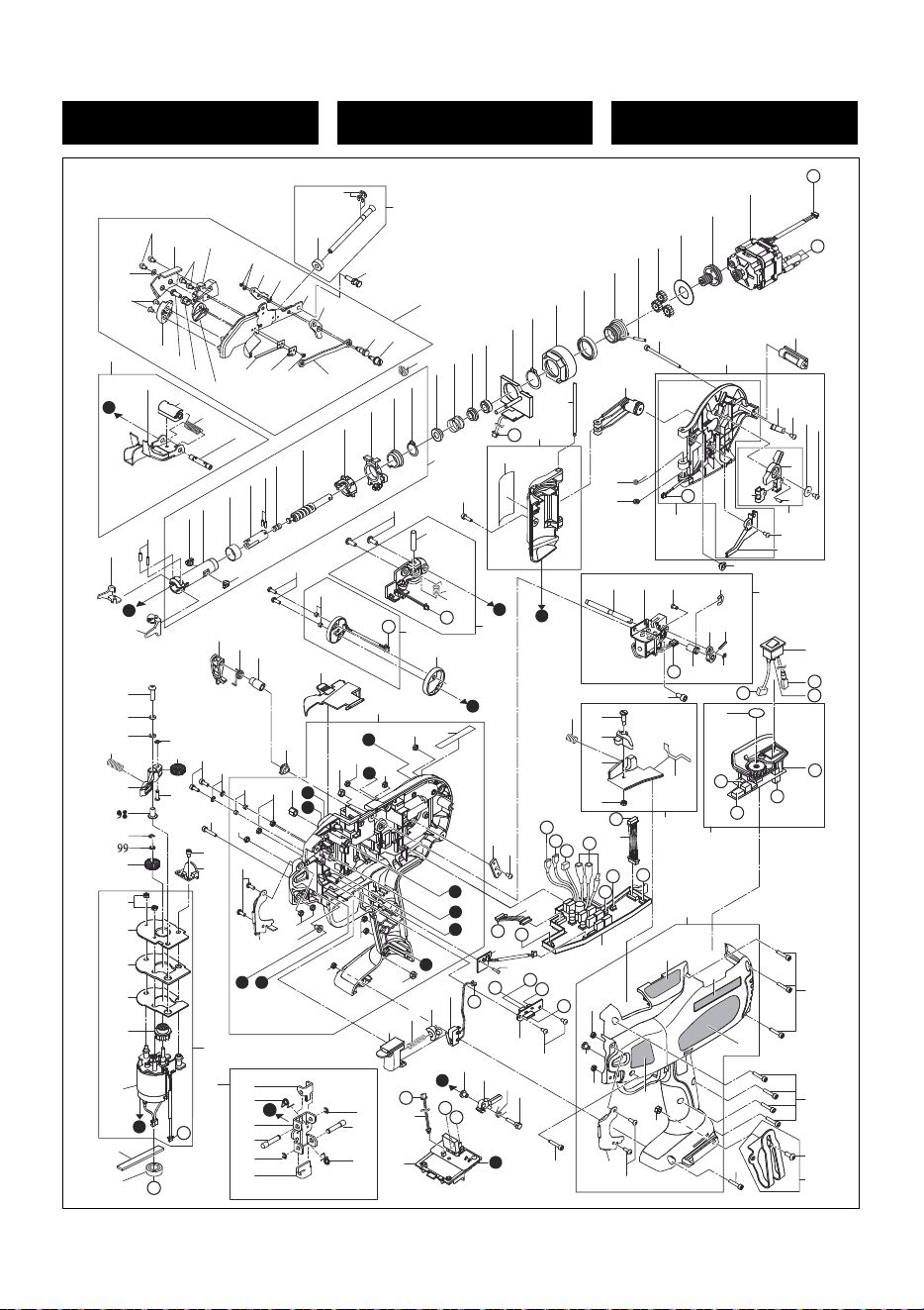
52
RB218
EXPLODED
VIEW AND SPARE PARTS LIST
SCHEMA ECLATE ET LISTE DES
PIECES DE RECHANGE
DESPIECE DE LA MAQUINA Y
LISTA DE RECAMBIOS
12
4
6
7
8
16
17
18
19
178
20
13
11
3
15
1
1
5
9
2
14
A
t
21
22
23
24
26
27
28
29
30
31
32
33
33
34
35
35
36
37
38
39
40
41
42
43
44
45
46
48
47
47
49
50
51
52
53
54
55
56
57
58
59
60
61
63
64
66
177
175
69
70
71
68
72
73
75
76
74
88
78
81
80
82
65
65
83
85
89
84
86
87
65
174
77
90
91
92
93
94
94
96
97
100
1
102
95
128
124
129
131
132
133
134
135
136
137
103
61
138
140
103
103
103
141
142
181
142
149
143
148
145
145
145
157
158
159
150
151
154
153
152
155
156
146
147
142
103
103
103
103
11 6
11 7
11 8
11 9
123
120
94
121
122
125
126
127
176
67
160
161
162
163
164
140
146
103
103
165
166
167
168
169
171
140
140
B
140
B
C
C
D
G
E
F
E
F
G
H
I
H
J
J
a
b
c
d
e
f
u
i
j
k
m
a
i
e
s
k
p
g
h
f
n
n
b
g
p
d
s
c
m
t
j
103
99
173
I
115
110
111
111
113
113
112
94
94
114
109
103
104
105
106
107
108
179
180
D
u
h

53
RB218
ESPAÑOLFRANÇAISENGLISHMATERIAL
ITEM
NO.
PART
NO.
1
2
3
4
5
6
7
8
9
10
11
12
13
14
15
16
17
18
19
20
21
22
23
24
26
27
28
29
30
31
32
33
34
35
36
37
38
39
40
41
42
43
44
45
46
47
48
49
50
51
52
53
54
55
56
57
58
59
60
BB40481
EE31122
RB12229
RB12230
FF41724
JJ10109
RB12090
JJ10514
RB10379
RB12710
RB10378
RB10392
AA22005
RB10525
RB70517
RB12228
RB12231
RB10540
AA25113
RB70516
KK33370
RB12003
RB12007
JJ10101
RB81207
RB70511
RB12010
KK33365
RB12110
RB70510
RB11102
RB81113
RB12014
RB12017
RB12016
RB70675
FF31599
KK23730
RB12708
RB12785
RB70412
RB12091
JJ21011
RB81274
RB12020
KK29026
RB12019
RB81177
JJ21603
RB10338
LL11181
RB70676
FF31589
RB10341
RB10484
RB70418
RB70413
AA21419
Steel
Steel
Steel
Steel
Steel
Steel
Steel
Steel
Steel
Steel
Steel
Steel
Steel
Steel
Steel
Steel
Steel
Stainless steel
Steel
Steel,stainless steel
Steel
Steel
Rubber
Steel
Steel,rubber
Steel
Stainless steel
Steel
Steel
Steel,stainless steel
Steel
Steel
Steel
Steel
Steel
Steel
Steel
Steel
Steel
Steel
Steel, PA
Steel
Steel
Steel, PA
Steel
Steel
Urethan rubber
Steel,PA,etc.
Steel
PA
Steel
Steel
Steel
Steel
Stainless steel
Steel
Steel
BOLT 3×5
WASHER 3×7
ARM B
WIRE GUIDE B
STEP PIN 1724
E-RING 2
CUTTER LEVER B (397)
E-RING 3 CF
FIXED CUTTER
SHAFT
CUTTER
PIN
OVAL COUNTER-SUNK SCREW 3X5
WIRE GUIDE A
ARM A UNIT
CUTTER LEVER A
CONNECTING ROD
UPPER CURL GUIDE LEAF SPRING
PAN-HEAD SCREW 2×4
ARM ASSY(RB217)
TORSION SPRING 3370
SCREW
PIPE SPONGE
E-RING 4
PIPE ASSY(RB217)
CURL GUIDE UNIT (217)
CURL GUIDE COVER
TORSION SPRING
STOPPER SHAFT
CURL GUIDE ASSY (RB217)
HOOK
SPRING PIN 2.5×10
KEY
SLEEVE A
SLEEVE GUIDE
TIP AXIS B
PARALELL PIN 1599
COMPRESSION SPRING 3730
TIP AXIS A
SLEEVE B
CUTTER RING UNIT
CUTTER RING GUIDE
C-RING 14
TIP AXIS ASSY
SPRING COLLAR
COMPRESSION SPRING 9026
BUMPER
TIP AXIS GUIDE ASSY 2
C-RING 20
INTERNAL GEAR
WHEEL 6704
PLANET CAGE UNIT
PARALELL PIN 1589
PLANET GEAR
GEAR PRESS WHEEL
SUN GEAR UNIT
TWISTING MOTOR
PAN-HEAD SCREW 3×8CF
BOULON 3×5
RONDELLE 3×7
BRAS B
GUIDE DE FIL “B”
BOULON Á GRADINS 1724
BAGUE 2
LEVIER DE COUTEAU “B” (397)
BAGUE 3 CF
COUTEAU FIXE
ARBRE
COUTEAU
GOUPILLE
VIS OVALE NOYEE 3X5
GUIDE DE FIL “A”
UNITE DE BRAS “A”
LEVIER DE COUTEAU “A”
BIELLE DE CONNEXION
RESSORT DE FEUILLE DE GUIDE DE BOUCLE SUPERIEURE
VIS A TETE PLATE 2×4
ENSEMBLE DE BRAS (RB217)
RESSORT DE TORSION 3370
VIS
EPONGE TUYAU
BAGUE 4
TUYAU ASSY (RB217)
DE GUIDE DE BOUCLE UNIT (217)
COUVERCLE DE GUIDE DE BOUCLE
RESSORT DE TORSION
ARBRE DE RESSORT
ENSEMBLE DE GUIDE DE BOUCLE (RB217)
CROCHET
GOUPILLE DE RESSORT 2.5×10
CLAVETTE
MANCHON “A”
GUIDE DE MANCHON
AXE DE BOUT “B”
GOUPILLE PARALLELE 1599
RESSORT À PRESSION 3730
AXE DE BOUT “A”
MANCHON “B”
UNITÉ DE BAGUE DE COUTEAU
GUIDE DE BAGUE DE COUTEAU
BAGUE EN "C" 14
ENSEMBLE D'AXE DE BOUT
COLLIER A RESSORT
RESSORT À PRESSION 9026
AMORTISSEUR
ENSEMBLE DE GUIDE D'AXE DE BOUT 2
BAGUE EN “C” 20
ENGRENAGES INTERNE
ROUE 6704
UNITÉ DE CAGE PLANÉTAIRE
GOUPILLE PARALLELE 1589
ENGRENAGE PLANETAIRE
ROUE DE PRESSION D’ ENGRENAGES
UNITE DE PIGNON SOLEIL
MOTEUR DE TORSION
VIS A TETE PLATE 3×8CF
PERNO 3×5
ARANDELA 3×7
BRAZO B
GUIA DE ALAMBRE “B”
PERNO ESCALONADO 1724
ANILLO EN E2
ANILLO EN E 3 CF
CORTADORA FIJA
ÁRBOL
CORTADORA
PERNO
TORNILLO AVELLANADO OVAL 3X5
GUIA DE ALAMBRE “A”
UNIDAD DE BRAZO “A”
PALANCA DE CORTADORA “A”
BIELA
BALLESTA GUÍA DE LA VOLUTA SUPERIOR
TORNILLO DE CABEZA LLANA 2×4
CONJUNTO DEL BRAZO (RB217)
MUELLE DE TORSION 3370
TORNILLO
ESPONJA DE TUBO
ANILLO EN E4
TUBO ASSY (RB217)
DE GUÍA DE ONDULACIÓN UNIT (217)
MUELLE DE TORSIÓN
ÁRBOL DE MUELLE
GRUPO DE GUÍA DE ONDULACIÓN (RB217)
GANCHO
PERNO DE MUELLE 2.5×10
CHAVETA
MANGUITO “A”
GUÍA DE MANGUITO
EJE DE EXTREMIDAD “B”
PERNO PARALELO 1599
MUELLE DE COMPRESIÓN 3730
EJE DE EXTREMIDAD “A”
MANGUITO “B”
UNIDAD DE ANILLO DE CORTE
GUÍA DE AN LLO DE CORTADORA
ANILLO EN "C" 14
GRUPO DE EJE DE EXTREMIDAD
COLLAR DE MUELLE
MUELLE DE COMPRESIÓN 9026
AMORTIGUADOR
CONJUNTO DE GUÍA DE EJE DE EXTREMIDAD 2
ANILLO EN “C” 20
ENGRANAJES INTERNOS
RUEDA 6704
PERNO PARALELO 1589
ENGRANAJES PLANETARIOS
UNIDAD CENTRAL DE ENGRANAJES
MOTOR DE TORSIÓN
TORNILLO DE CABEZA LLANA 3×8CF
PALANCA DE CORTADORA “B” (397)
CUBIERTA DE GUÍA DE ONDULACIÓN
RUEDA DE PRESIÓN DE ENGRANAJES
UNIDAD DE JAULA PLANETARIA

54
RB218
ESPAÑOLFRANÇAISENGLISHMATERIAL
ITEM
NO.
PART
NO.
61
63
64
65
66
67
68
69
70
71
72
73
74
75
76
77
78
80
81
82
83
84
85
86
87
88
89
90
91
92
93
94
95
96
97
98
99
100
101
102
103
104
105
106
107
108
109
110
111
112
113
114
115
116
117
118
119
120
121
FF51817
RB81246
RB12284
AA05555
RB11687
BB41706
FF31563
KK34089
RB81181
BB40715
RB12100
RB70401
FF41871
KK34067
EE39609
BB40714
RB12031
RB81178
RB81179
RB12038
EE39184
RB12035
FF21240
RB12036
RB70427
RB81180
RB12099
BB41707
EE11103
EE39825
KK24175
JJ10113
RB10359
RB10362
FF41809
FF51628
EE32104
RB10357
RB10364
CC41104
RB70434
RB12045
RB12421
RB70509
RB81266
RB81267
RB12773
KK33420
RB12775
FF41822
RB12774
RB70739
RB12238
RB81185
FF41855
JJ10106
RB12030
RB12029
Steel
PA,steel,etc.
Stainless steel
Steel
Steel
Steel
Steel
Stainless steel
Steel,stainless steel,PC,etc
Steel
PET
PET,PA
Steel
Stainless steel
Urethan rubber
Steel
PA
PA,stainless steel,steel
PA,steel,etc.
Stainless steel
Steel
POM
Steel
Stainless steel
POM,steel,stainless steel
Steel
Steel
Steel
Steel
Steel
Steel
Steel
Aluminum
Steel
Steel
Stainless steel
Steel
Steel
Steel
Aluminum,steel
Rubber
Aluminum
Steel,PA
Steel,aluminum,PA,etc.
Steel
Steel
Steel
Steel
Steel
Steel
Steel
Steel
Steel
Steel
Steel
RPA,PC,POM,steel,
stainless steel,etc
HOLLOW PIN 1817
REEL GUIDE ASSY
REEL GUIDE
SCREW M3×6 CF
NUT PLATE
BOLT 4X10 CF
PARALLEL PIN 1563
TORSION SPRING 4089
RATCHET COVER ASSY
BOLT 3X12
WARNING LABEL A (CE)
MOTOR COVER A (397CE)
STEP PIN 1871
TORSION SPRING 4067
PLANE RUBBER WASHER 1.8X6X2
BOLT 3X50 CF
JOINT
REEL HOLDER ASSY
REEL MAGAZINE
REEL STOPPER SPRING
PLANE WASHER 3.1X11.8X1
REEL STOPPER
SPRING PIN 2.5×6
STOPPER PLATE
REEL STOPPER ASSY
REEL MAGAZINE ASSY
PLATE B
BOLT 4X16 CF
SPRING WASHER 2-4
PLANE WASHER 4.5X7.4X0.8
COMPRESSION SPRING 4175
E-RING 2.5
FEEDING GEAR B2
RELEASE LEVER
STEP PIN 1809
HOLLOW PIN 1628
WASHER 2-3
FEEDING GEAR B1 ASSY
WIRE GUIDE C
HEX, NUT 1-3
PARTITION PLATE
PARTITION SPONGE
SPONGE SUPPORT
FEEDING GEAR A ASSY
FEEDING MOTOR ASSY
FEEDING ASSY
JAW A
TORSION SPRING 3249
JAW BASE
STEP PIN 1822
JAW B
JAW BASE ASSY
ROTARY PIN
SOLENOID ASSY
STEP PIN 1855
E-RING 6
PLATE C
ROTARY PLATE
GOUPILLE CREUSE 1817
ENSEMBLE DE GUIDE DE BOBINE
GUIDE DE BOBINE
VIS M3×6 CF
PLAQUE DE ÉCROU
BOULON 4X10 CF
GOUPILLE PARALLELE 1563
RESSORT DE TORSION 4089
ENSEMBLE DE COUVERCLE DE RACHET
BOULON 3X12
PLAQUE D’AVERTISSEMENT A (CE)
COUVERCLE DE MOTEUR “A” (CE)
BOULON À GRADINS 1871
RESSORT DE TORSION 4067
BOULON 3X10 CF
JOINT
ENSEMBLE DE PORTE-BOBINE
MAGASIN DE BOBINE
RESSORT DE PIECE DE RETENUE DE BOBINE
RONDELLE LISSE 3.1X11.8X1
PIECE DE RETENUE DE BOBINE
GOUPILLE DE RESSORT 2.5×6
PLAQUE DE PIéCE DE RETENUE
ENSEMBLE DE TAQUET DE BOBINE
MAGASIN DE BOBINE ASSY
PLAQUE “B”
BOULON 4X16 CF
RONDELLE DE RESSORT 2-4
RONDELLE 4.5×7.4×0.8
RESSORT À PRESSION 4175
BAGUE 2.5
B2 D’ENGRENAGES D’AVANCE
LEVIER DE DECLENCHEMENT
BOULON À GRADINS 1809
GOUPILLE CREUSE 1628
RONDELLE 2-3
ENSEMBLE “B1” D’ ENGRENAGES D’AVANCE
GUIDE DE FIL “C”
ECROU HEXAGONAL 1-3
PLAQUE DE DIVISION
EPONGE DE DIVISION
SUPPORT D'EPONGE
ENSEMBLE “A” D’ ENGRENAGES D’AVANCE
MOTEUR D’AVANCE ASSY
ENSEMBLE D'AVANCE
MACHOIRE “A”
RESSORT DE TORSION 3249
BASE DE MACHOIRE
BOULON À GRADINS 1821
MACHOIRE “B”
BASE DE MACHOIRE ASSY
GOUPILLE ROTATIVE
ENSEMBLE DE SOLENOIDE
BOULON À GRADINS 1855
BAGUE 6
PLAQUE “C”
PLAQUE ROTATIVE
PERNO DE ALAMBRE 1817
CONJUNTO DE GUÍA DE CARRETE
GUÌA DE BOBINA
TORNILLO M3×6 CF
PLACA DE TUERCA
PERNO 4X10 CF
PERNO PARALELO 1563
MUELLE DE TORSIÓN 4089
GRUPO DE CUBIERTA DEL TRINQUETE
PERNO 3X12
RÓTULO AVISADOR DE PELIGRO A (CE)
CUBIERTA DE MOTOR “A” (CE)
PERNO ESCALONADO 1871
MUELLE DE TORSION 4067
ARANDELA DE CAUCHO LISA 1,8X6X2
PERNO 3X10 CF
JUNTA
GRUPO DE PORTA BOBINA
ALOJAMIENTO DE BOBINA
MUELLE DE RETÉN DE CARRETE
ARANDELA LISA 3.1X11.8X1
PIEZA DE RETENClÓN DE BOBINA
PERNO DE MUELLE 2.5×6
PLACA DE PARTE DE RETENCIîN
CONJUNTO DE BLOQUE DE CARRETE
ALOJAMIENTO DE BOBINA ASSY
PLACA “B”
PERNO 4X16 CF
ARANDELA DE MUELLE 2-4
ARANDELA 4.5×7.4×0.8
MUELLE DE COMPRESIÓN 4175
ANILLO EN E2.5
B2 DE ENGRANAJES DE ALIMENTACIÓN
PALANCA DE DISPARO
PERNO ESCALONADO 1809
PERNO DE ALAMBRE 1628
ARANDELA 2-3
GRUPO “B1” DE ENGRANAJES DE ALIMENTACIÓN
GUÍA DE ALAMBRE “C”
TUERCA HEXAGONAL 1-3
PLACA DE DIVISlÓN
ESPONJA DE DIVISIÓN
SOPORTE DE ESPONJA
GRUPO “A” DE ENGRANAJES DE ALIMENTACIÓN
MOTOR DE ALIMENTACIÓN ASSY
CONJUNTO DE ALIMENTACIÓN
QUIJADA “A”
MUELLE DE TORSIÓN 3249
BASE DE QUIJADA
PERNO ESCALONADO 1822
QUIJADA “B”
BASE DE QUIJADA ASSY
PASADOR GIRATORIO
CONJUNTO DE SOLENOIDE
PERNO ESCALONADO 1855
ANILLO EN E6
PLACA “C”
PLACA GIRATORIA
RONDELLE LISSE EN CAOUTCHOUC
1.8X6X2

55
RB218
ESPAÑOLFRANÇAISENGLISHMATERIAL
ITEM
NO.
PART
NO.
122
123
124
125
126
127
128
129
131
132
133
134
135
136
137
138
140
141
142
143
145
146
147
148
149
150
151
152
153
154
155
156
157
158
159
160
161
162
163
164
165
166
167
168
169
171
173
174
175
176
177
178
179
180
181
FF21620
RB70531
BB40712
RB12025
KK33373
FF52114
RB70457
RB12234
RB81209
RB12054
RB12053
RB12055
RB12056
RB81139
KK29133
BB40710
BB40709
RB12236
CC42512
RB12521
FF52111
BB41503
RB12226
RB81270
RB11987
RB81195
RB81191
AA31724
RB12080
KK23656
RB12101
RB70453
RB70473
KK34083
RB11686
RB70522
RB70465
RB70454
RB81188
RB70464
RB12224
RB11983
RB11985
RB12237
RB12524
RB70599
RB81184
RB12039
BB41708
AA31722
AA31721
RB11141
PJ70345
RB12423
RB81268
RB12119
Stainless steel
Steel,stainless steel,etc.
Steel
Steel
Stainless steel
Steel
PET
PC,POM,steel,stainless steel,etc.
Steel
POM
PC
Rubber
PC,POM,steel,rubber
Steel
Steel
Steel
Steel
Steel
PET
Steel
Steel
Steel
PA,PET,steel,copper alloy
PC
Steel
POM
Steel
PC
PC,steel
Stainless steel
Steel
PBT,copper,steel,etc.
Steel
PET
PET
PET
PET
PA,PET,steel
Steel
PC
Steel
Steel
Steel
Steel
Stainless steel
Rubber
Steel
,
Rubber
Steel
SPRING PIN 2×12
BRAKE ASSY
BOLT 4X8 CF
REEL PRESS
TORSION SPRING 3373
HOLLOW PIN 2114
MAIN SWITCH UNIT(RB397)
DIAL LABEL
SWITCH BASE ASSY(217)
STEP PIN
RELEASE STOPPER
STOPPER BASE
SPONGE F
STOPPER BASE ASSY
COMPRESSION SPRING 9133
BOLT 3X8 CF
BOLT 3X16 CF
PLATE A
HEX, NUT M4 CF
WARNING LABEL (398)
HOLLOW PIN 2111
BOLT 3X8 CF
COVER L (217)
FRAME L ASSY (218)
WINDOW
RELAY BOARD UNIT
SENSOR CIRCUIT BOARD D UNIT
PAN-HEAD SCREW 2×8
TRIGGER(RB397)
COMPRESSION SPRING 3656
TRIGGER LOCK LEVER (RB397)
TRIGGER SWITCH UNIT(RB397)
SWITCH LEVER UNIT
TORSION SPRING 4083
SWITCH LEVER PIN
MAIN CIRCUIT BOARD UNIT(RB217)
RELAY BOARD HARNESS UNIT
INTERFACE HARNESS UNIT (RB397)
ELECTRODE UNIT
BATTERY SIGNAL HARNESS UNIT
COVER R(217)
LABEL, CURL GUIDE
USAGE LABEL
LABEL, MAIN SWITCH
218 LABEL (218USA)
FRAME R ASSY (518USA)
BELT HOOK ASSY
LED COVER
BOLT 4X10 CF
SCREW M3X8 CF
SCREW M3×6 CF
LEAF SPRING GUIDE
LATCH ASSY
RING CORE SPONGE
RING CORE UNIT
HEX NUT M4
GOUPILLE DE RESSORT 2×12
ENSEMBLE DE FREIN
BOULON 4X8 CF
PRESSE DE BOBINE
RESSORT DE TORSION 3373
GOUPILLE CREUSE 2114
UNITÉ DE INTERRUPTEUR GENERAL (RB397)
ETIQUETTE DU CADRAN
BASE DE COMMUTATEUR (217)
BOULON À GRADINS
PIECE DE RETENUE DE DECLENCHEMENT
BASE DE RETENUE
EPONGE F
ENSEMBLE DE LA BASE DE RETENUE
RESSORT À PRESSION 9133
BOULON 3X8 CF
BOULON 3X16 CF
PLAQUE “A”
ECROU HEXAGONAL M4 CF
JOINT D'AVERTISSEMENT (398)
GOUPILLE CREUSE 2111
BOULON 3X8 CF
COUVERCLE “L” (217)
ENSEMBLE DU CADRE "L" (218)
FENÊRE
UNITE DE PLAQUETTE DE RELAIS
UNITE DE PLAQUETTE DE CIRCUIT DE SENSEUR "D"
VIS A TETE PLATE 2×8
LEVIER DE COMMANDE (RB397)
RESSORT À PRESSION 3656
LEVIER DE BLOCAGE DE LA COMMANDE (RB397)
COMMUTATEUR DE DECLENCHEUR (RB397)
UNITÉ DE LEVIER DE COMMUTATEURS
RESSORT DE TORSION 4083
GOUPILLE DE LEVIER DE COMMUTATEURS
UNITE PRINCIPALE DE PLAQUETTE DE CIRCUITS IMPRIMES (RB217)
UNITE DE FAISCEAU DE PLAQUETTE DE RELAIS
UNITE DE FAISCEAU D'INTERFACE (RB397)
UNITE D'ELECTRODE
UNITE DE FAISCEAU DE SIGNAL DE LA BATTERIE
COUVERCLE “R” (217)
PLAQUE DE GUIDE DE BOUCLE
JOINT PR
PLAQUE INTERRUPTEUR GENERAL
PLAQUE SIGNALÉTIQUE (218USA)
ENSEMBLE DU CADRE "R" (518USA)
ENSEMBLE DU CROCHET DE COURROIE
COUVERCLE DE-DEL
BOULON 4X10 CF
VIS M3X8 CF
VIS M3 × 6 CF
GUIDE DU RESSORT A LAMES
DISPOSITIF DE VERROUILLAGE
ÉPONGE À NOYAU TOROÏDAL
UNITÉ À NOYAU TOROÏDAL
ECROU HEXAGONAL M4
PERNO DE MUELLE 2×12
CONJUNTO DE FRENO
PERNO 4X8 CF
PRENSA DE BOBINA
MUELLE DE TORSIÓN 3373
PERNO DE ALAMBRE 2114
UNIDAD DE INTERRUPTOR GENERAL (RB397)
PLACA DE DIAL
BASE DE CONMUTADOR (217)
PERNO ESCALONADO
PIEZA DE RETENCIÓN DE DISPARO
BASE DE RETENCIÒN
ESPONJA F
GRUPO DE LA BASE DEL RETÉN
MUELLE DE COMPRESIÓN 9133
PERNO 3X8 CF
PERNO 3X16 CF
PLACA “A”
TUERCA HEXAGONAL M4 CF
JUNTA DE ADVERTENCIA (398)
PERNO DE ALAMBRE 2111
PERNO 3X8 CF
CUBIERTA “L” (217)
GRUPO DEL BASTIDOR "L" (218)
VENTANILLA
UNIDAD DE PLACA DE RELÉ
UNIDAD DE PLACA DE CIRCUITO DE SENSOR "D"
TORNILLO DE CABEZA LLANA 2×8
PALANCA DE ACCIONAMIENTO (RB397)
MUELLE DE COMPRESIÓN 3656
PALANCA, BLOQUEODE ACCIONAM ENTO (RB397)
CONMUTADOR DE DISPARO (RB397)
UNIDAD DE LA PALANCA DEL INTERRUPTOR
MUELLE DE TORSIÒN 4083
PERNO DE PALANCA DEL INTERRUPTOR
UNIDAD DE TARJETA DE CIRCUITOS PRINCIPAL (RB217)
UNIDAD DE CABLEADO DE PLACA DE RELÉS
UNIDAD DE CABLEADO DE INTERFAZ (RB397)
UNIDAD DE ELECTRODO
UNIDAD DE CABLEADO DE SEÑAL DE BATERÍA
CUBIERTA “R” (217)
PLACA, DE GUÌA DE ONDULACIÓN
PLACA DE INDICACIONES DE USO
PLACA, INTERRUPTOR GENERAL
PLACA DE CARACTERÍSTICAS (218USA)
GRUPO DEL BASTIDOR "R" (518USA)
GRUPO DEL GANCHO DE LA CORREA
CUBIERTA DE LED
PERNO 4X10 CF
TORNILLO M3X8 CF
TORNILLO M3×6 CF
GUÍA DE RESORTE DE LÁMINA
CONJUNTO DEL PESTILLO
ESPONJA DE NÚCLEO ANULAR
UNIDAD DE NÚCLEO ANULAR
TUERCA HEXAGONAL M4

• The content of this manual might be changed without notice for improvement.
• El contenido de este manual puede sufrir modificaciones sin previo aviso para la introducción de
mejoras.
• Le contenu du présent manuel est sujet à modification sans préavis, en vue d'y apporter des
améliorations.
4101093
210727-00/04
PRINTED IN JAPAN
205 Express Street
Plainview, NY 11803, U.S.A.
TEL: 1-800-223-4293
FAX: (516)741-3272
maxcorp@maxusacorp.com
www.maxusacorp.com