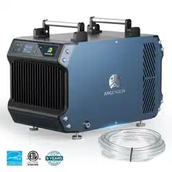
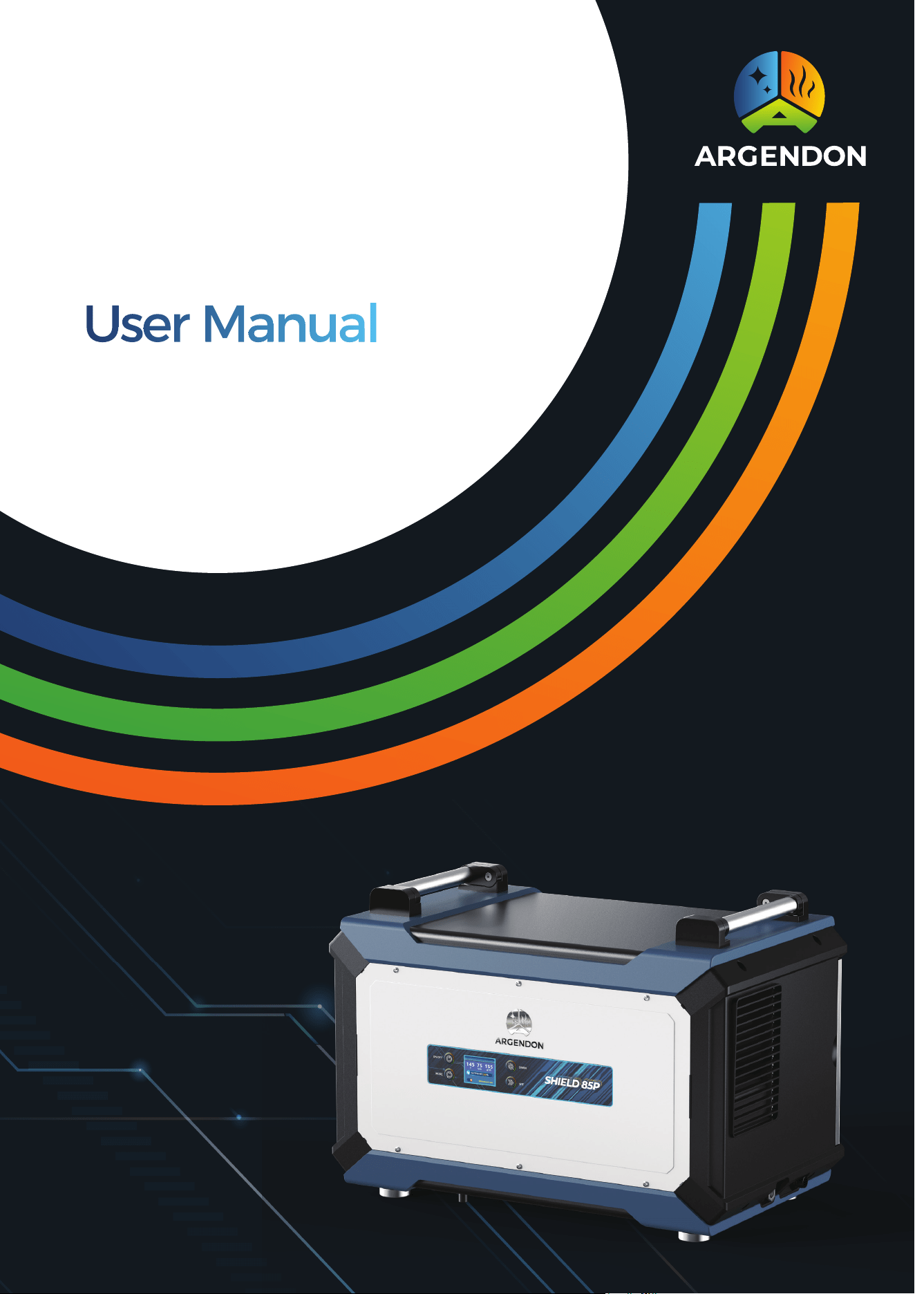
Commercial & Home Dehumidifier
SHIELD 85P


● Important Instruction ●
1. Power Source:
Always connect your dehumidifier to an earthed power source (grounded outlet).
This is essential for the proper functioning of the appliance. Failure to use a
grounded power source will void the warranty.
2. Qualified Technician:
For any repairs or maintenance, only trust a qualified technician. Attempting to
repair the dehumidifier yourself may result in damage or voiding of the warranty.
3. Water Exposure:
In the event of potential water flooding, ensure the dehumidifier is thoroughly
dried before reconnecting power and restarting. This precautionary measure
helps prevent electrical hazards.
4. Air Inlet and Outlet:
Do not insert any objects or fingers into the air inlet or outlet of the dehumidifier.
This is crucial to maintain the optimal performance and safety of the appliance.
5. Cleaning:
Refrain from washing the exterior of the dehumidifier with water. To clean the
unit, unplug it and gently wipe the outside with a damp cloth. This ensures proper
cleaning without compromising the internal components.
6. Weight and Objects:
Avoid standing on the dehumidifier or placing any objects on it. Such actions may
damage the unit and pose safety risks.
7. Extension Cords and Adapters:
Do not use extension cords or plug adapters with the dehumidifier. Connecting
the appliance directly to a suitable power source is necessary for its safe and
efficient operation.
8. Maintenance:
Unless otherwise stated, always perform maintenance tasks when the
dehumidifier is powered off. This includes any cleaning, filter replacements, or
other routine maintenance activities.

Warranty Registration 1
Electrical Supply Information and
Safety Guidelines 1
Principle of Operation 2
Installation Guidelines 2
Key Functions 3
Function Description 6
Maintenance 10
Error Code Guide 11
Circuit Diagram 11
Limited Warranty 12
Limited Warranty Exclusions 12
Table of Content

1
Warranty Registration
To ensure a seamless support experience, please take a moment to register your warranty by
recording the model, serial number, and date of purchase as indicated below. This information is
important for any future assistance you may require.
**The data label is located on the side of your unit.**
Model: Shield 85P
Serial Number: __________________ Date of Purchase: __________________
For additional questions concerning your dehumidifier, the following options are available:
Contact your installing contractor.
E-mail: sales@argendon.com.
Electrical Supply Information and Safety Guidelines
Electrical Supply Specifications:
• Power Supply: 115 V, 60 Hz AC, Single Phase
• Outlet Requirement: 3-Prong, GFCI (Ground Fault Circuit Interrupter)
• Circuit Protector: 15 Amps
Important Warning:
WARNING: 240 Volts AC may cause serious injury from electric shock.
To reduce the risk of injury, please follow these safety guidelines:
1. Disconnect Power Before Servicing:
Always disconnect the electrical power before servicing or conducting any maintenance on
the dehumidifier. This ensures your safety and prevents the risk of electric shock.
2. Grounded Electrical Circuit:
Only plug the unit into a grounded electrical circuit. Ensure that the outlet meets the
specified requirements, including the use of a 3-prong outlet with a Ground Fault Circuit
Interrupter (GFCI).
3. Avoid Extension Cords:
Do not use an extension cord with your dehumidifier. Connecting the unit directly to a
suitable power source is essential for safe and reliable operation.
4. Avoid Plug Adapters:
Do not use a plug adapter. Ensure that the plug on the dehumidifier matches the
configuration of the outlet. Using an adapter may compromise the electrical connection and
pose safety risks.

2
Principle of Operation
Your dehumidifier operates seamlessly to manage the humidity levels in your space. Here's how
it works:
The integral humidistat monitors the relative humidity in the room. When the humidity exceeds
the selected set point, the dehumidifier activates.
Air is drawn across a cooler evaporator coil. This cooler temperature causes moisture to condense
out of the air.
The dehumidified air then passes through a condenser coil, where it is reheated.
The final step involves distributing the now dehumidified and reheated air back into the room.
This cycle repeats as necessary to maintain the desired relative humidity level in the space.
Installation Requirements
To ensure optimal performance and safety, follow these installation requirements for your
dehumidifier:
1. Enclosed Environment:
Place the dehumidifier in a closed environment, ensuring that the working area is enclosed to
facilitate effective moisture removal.
2. Ventilation Clearance:
Provide proper ventilation by avoiding placement against a wall for both the entrance and
exit sides. Maintain a minimum clearance of 6 inches for both the inlet and outlet to promote
efficient air circulation.
3. Central Placement for Maximum Effect:
To achieve the best dehumidification results, position the dehumidifier at the center of the
room. This central placement enhances its ability to address moisture levels evenly throughout
the space.
4. Upright and Level Operation:
The dehumidifier is designed for upright operation, and it should be positioned level with the
floor. Ensure the machine is set up in this manner to guarantee proper functionality and optimal
performance.
3
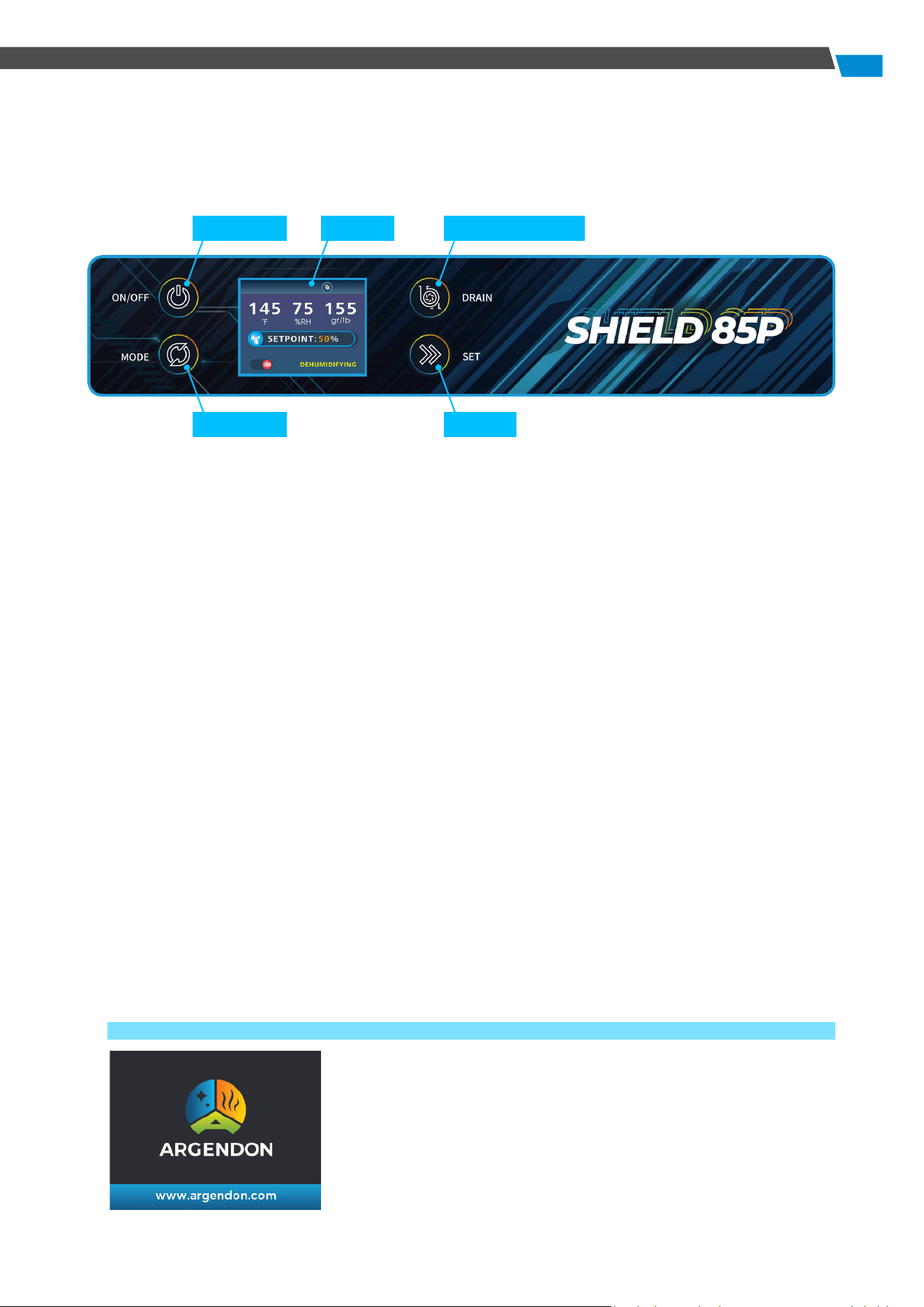
Key Functions
The machine will enter the screen-off state after some times of no operation. Press any key to
wake up the display window to activate all modes. The machine will beep after successful
operation.
1. Power Key
Press this key to turn the dehumidifier on and off.
The Power Key provides control over the unit's operation status.
2. Mode Key
Use this key to scroll through the operation interface, facilitating easy selection of different
modes and settings.
3. Set Key
Press this key to set the desired humidity level or moisture content. Additionally, use the Set Key
to toggle the continuous dehumidification mode on or off. It also serves to activate or deactivate
the GPP (Grains Per Pound) mode.
4. Water Pump Key
Hold this key for 3 seconds to control the water pump function, turning it on and off. When the
water pump function is active, a short press of the DRAIN Key will initiate a 28-second force
drainage.
5. Display Window
The display window provides essential information through various interfaces, including
start-up animation, shutdown interface, main interface, coil temperature display, continuous
dehumidification mode selection, GPP mode selection, humidity setting, moisture content
setting, and fault display. This window serves as a comprehensive visual guide to the
dehumidifier's status and settings.
1) Boot
When the unit is powered on, it will present a boot screen. This
screen serves as an initial display before entering the operation
screen.
Power Key Display
Mode Key
Water Pump Key
Set Key
4
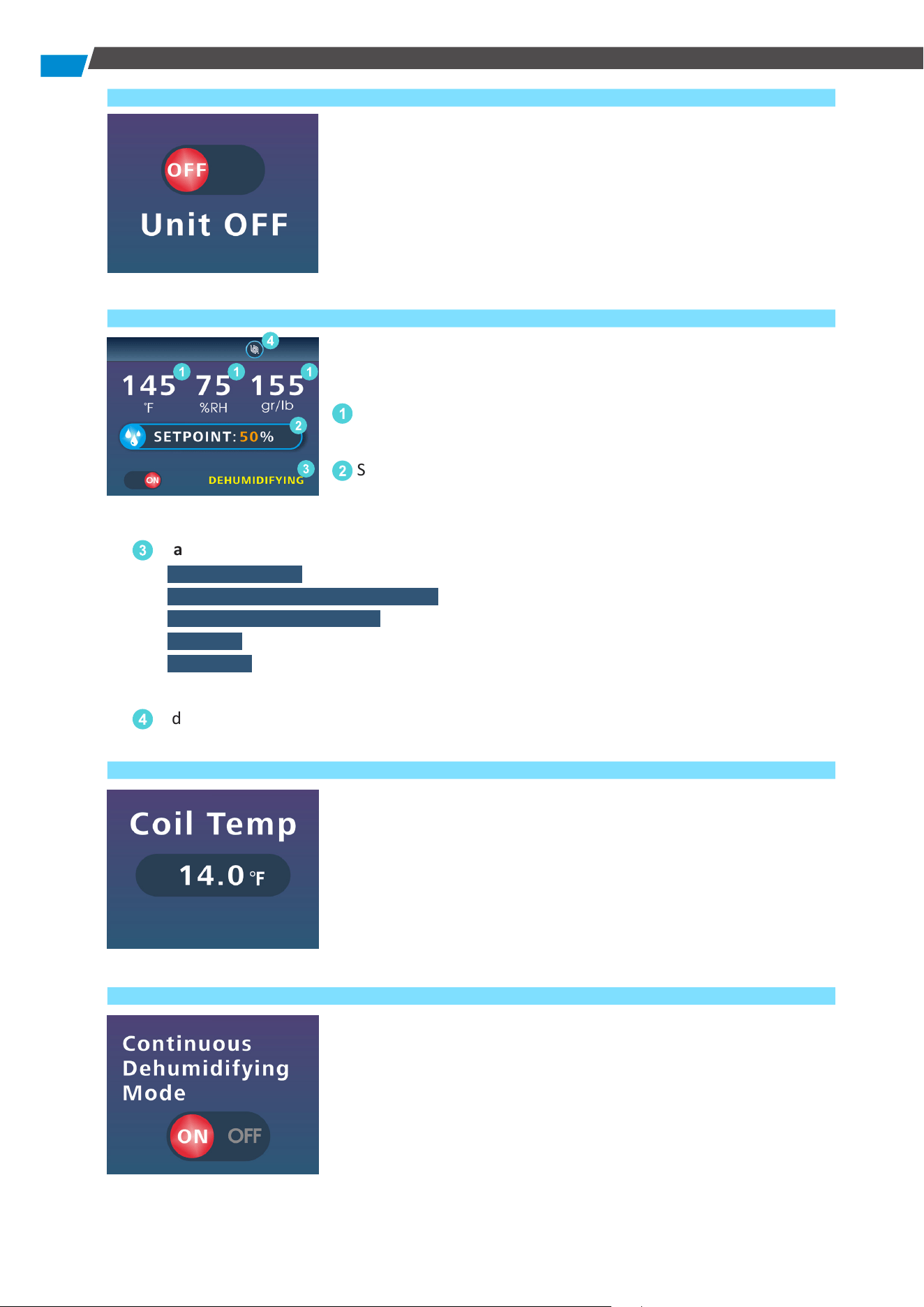
2) Power Off
This screen is displayed when the unit is shutting down.
3) Main User Interface
Explore the comprehensive details presented on the Main User
Interface Screen when your dehumidifier is operational:
1
Real-time information on the current temperature, humidity,
and moisture content.
2
Shows the set humidity level or moisture content. In GPP
mode, it displays the currently set humidity level, while in
continuous dehumidification mode, it indicates "CO."
3
Machine Working Status Display: Provides the current working status of the appliance.
" DEHUMIDIFYING " is displayed during dehumidification mode,
" CONTINUOUS DEHUMIDIFICATION " appears during continuous dehumidification,
" PLEASE WAIT COMP. RELAY " signifies compressor protection mode,
" DEFROST " indicates defrost status.
" DRAINING " is displayed when the water pump is active. This column is absent when the
appliance is in a dehumidification completed state.
4
Indicates whether the water pump function is active.
4) Coil Temperature Display
Press the MODE Key to access the coil temperature display,
showing the current temperature of the coil.
● Error Alert: In case of a coil temperature sensor failure, the
display will show "14.0 °F" to indicate the issue.
5) Continuous Dehumidification Mode Selection
Press the MODE key to manage continuous dehumidification. To
activate or deactivate the continuous dehumidification mode,
press the SET key. The dehumidifier will then operate according
to your chosen settings.
1
2
3
1 1
4
5
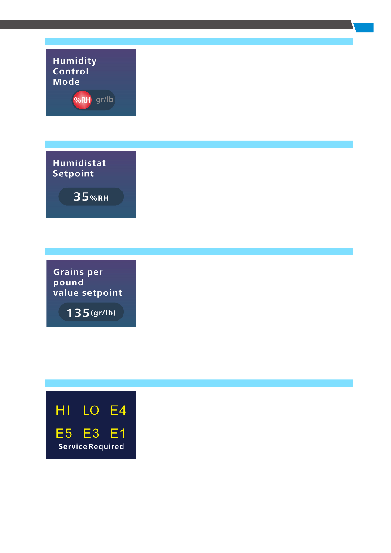
6) GPP Mode Selection
Press the MODE Key to enter the GPP mode. To enable or disable
GPP mode, press the SET Key. The device will then operate in
accordance with your configured settings.
7) Humidity Setting
Press MODE to access the humidity setting screen. Use SET to
choose your desired humidity level from 35% to 90%. Press and
hold for quick adjustments.
The unit operates based on the selected setting, prioritizing
continuous dehumidification mode, GPP mode, and then,
humidity control.
8) Moisture Content Adjustment
Press MODE to access the Moisture Content Setting Screen. Press
SET to configure the moisture content within the range of 25% to
200%. Press and hold for quick adjustments, with a 2% increase
per press during the setting process. Once set, the unit operates
accordingly.
You have the option to disable continuous dehumidification
mode or GPP mode. However, the unit prioritizes the following
sequence: continuous dehumidification mode, GPP mode, and
then humidity control.
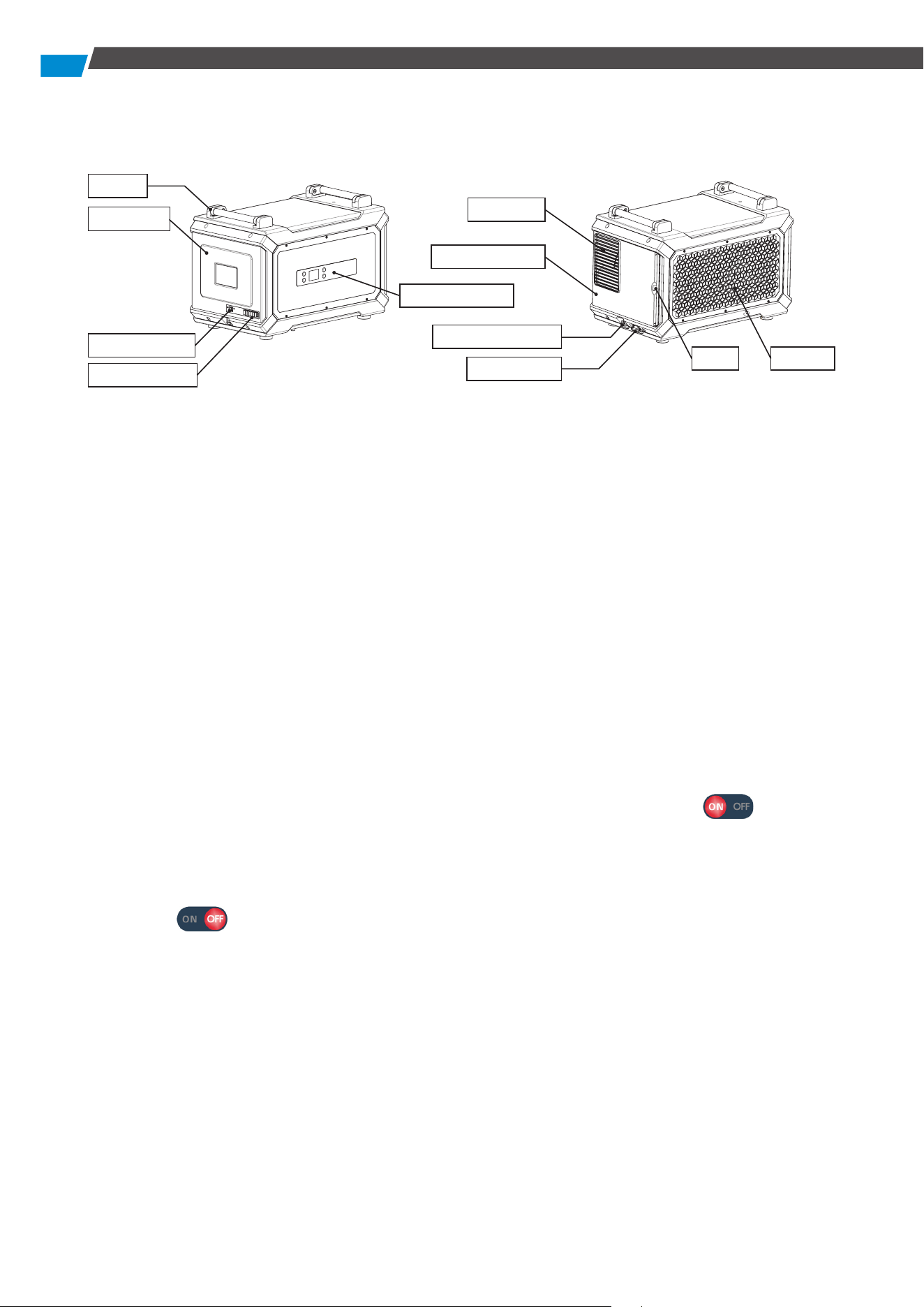
9) Error Display
This interface appears when an error occurs (refer to the Error
Code section below).
6
Function Description
All illustrations in this manual are for illustrative purposes only.
The actual appearance and functions depend on the product purchased.
1. Dehumidification Humidity Setting
Power on the unit and press the MODE Key to access the humidity (moisture content) setting
interface. Use the SET Key to establish the desired humidity within the range of 35% to 90%
and the moisture content of 25% to 200%. Pressing the Key increases the humidity by 1% RH
(or 2% moisture content), and pressing and holding adjusts the set value. If there's no input for
3 seconds after setting, the device runs according to the configured status and returns to the
main interface, displaying "DEHUMIDIFYING" in the status bar. When the humidity reaches the
set value, the unit enters standby mode, and the main interface status bar is empty. If humidity
rises, the unit resumes automatic operation based on the set status.
2. Continuous Dehumidification Mode
When the unit is powered on, press the MODE Key to enter continuous dehumidification. On
this interface, press the SET Key to activate CO mode. The display will indicate the mode
is activated. Return to the main interface and set the humidity column to display "CO."
In CO mode, the unit operates independently of changes in humidity. To turn off continuous
dehumidification mode, navigate to the CO mode selection interface and the display will
indicate that CO mode is off.
3. Power-off Memory Function
In case of a power outage during operation, the unit will automatically resume its previous
mode and state when powered on again.
**Note that due to a three-minute compressor protection function, there is a brief delay before
the unit restarts. It is normal for the fan to undergo a short status change between starting
and stopping. The memory function contains settings such as humidity, moisture content,
continuous operation, GPP function, and water pump function.
4. Grains Per Pound (GPP) Function
Activate GPP Mode, by pressing the MODE Key to access the GPP Mode selection interface, then
Handle
Air Outlet
Air Inlet
Air Outlet Panel
Water Pump Drain
Gravity Drain
Filter
Rear Panel
Cable Interface
A1-A6 Interface
Operation Panel
7
press the SET Key. The interface will indicate that GPP Mode is on . Next, return to the
main interface and set the humidity to display the humidity level. When the GPP mode is off,
the main interface displays the humidity level. However, on the GPP mode selection interface,
the display signifies that GPP mode is off . When GPP mode is activated, the device
operates according to the configured moisture content level.
5. Automatic Defrosting Function
The appliance has an automatic defrost function. If the ambient temperature is too low and
frost forms on the surface of the system, it is defrosted automatically. During defrosting,
"DEFROST" is displayed in the working status bar of the appliance on the main interface. After
defrosting, the appliance automatically returns to the initial state and the status bar on the main
interface displays the current working status.
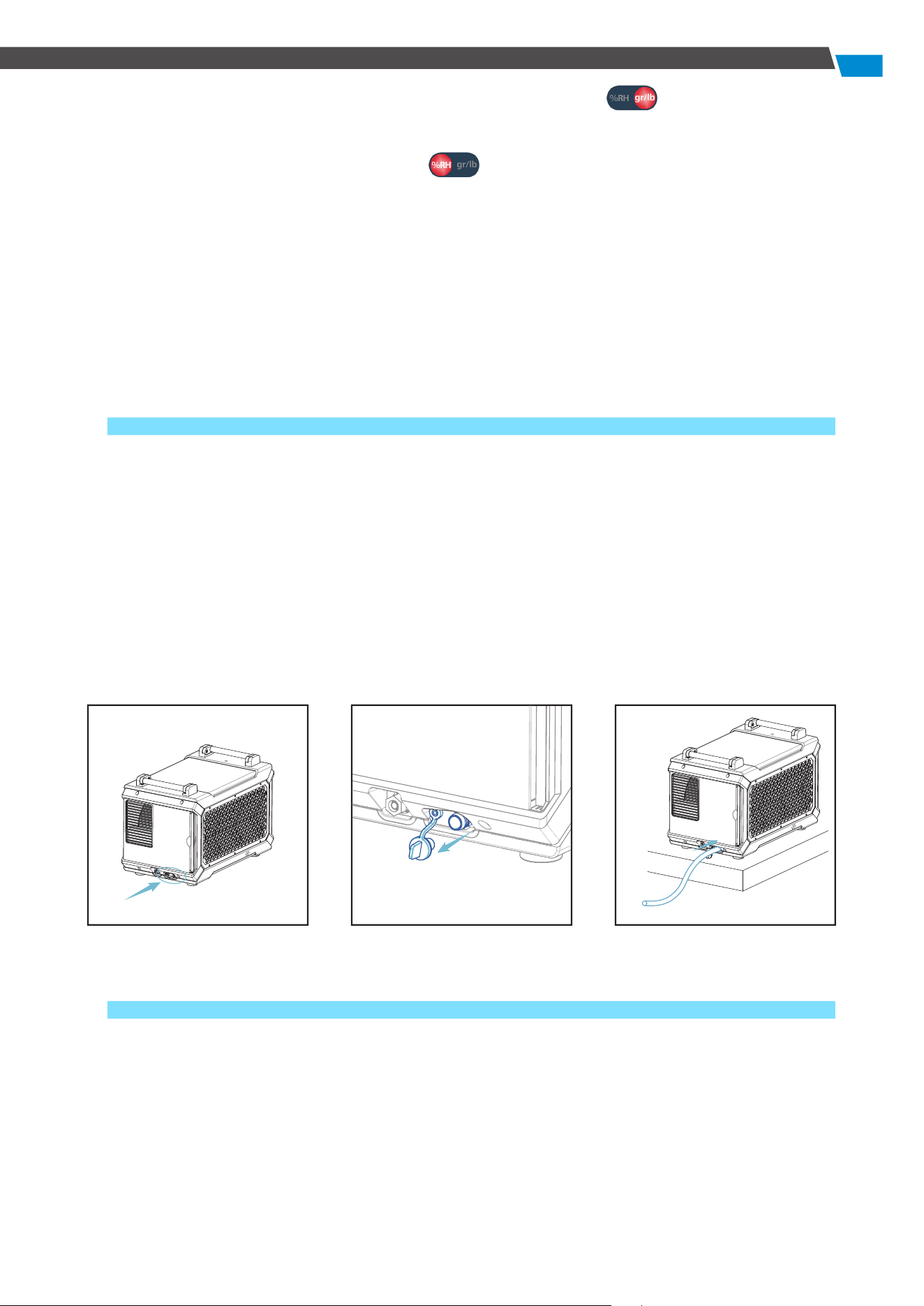
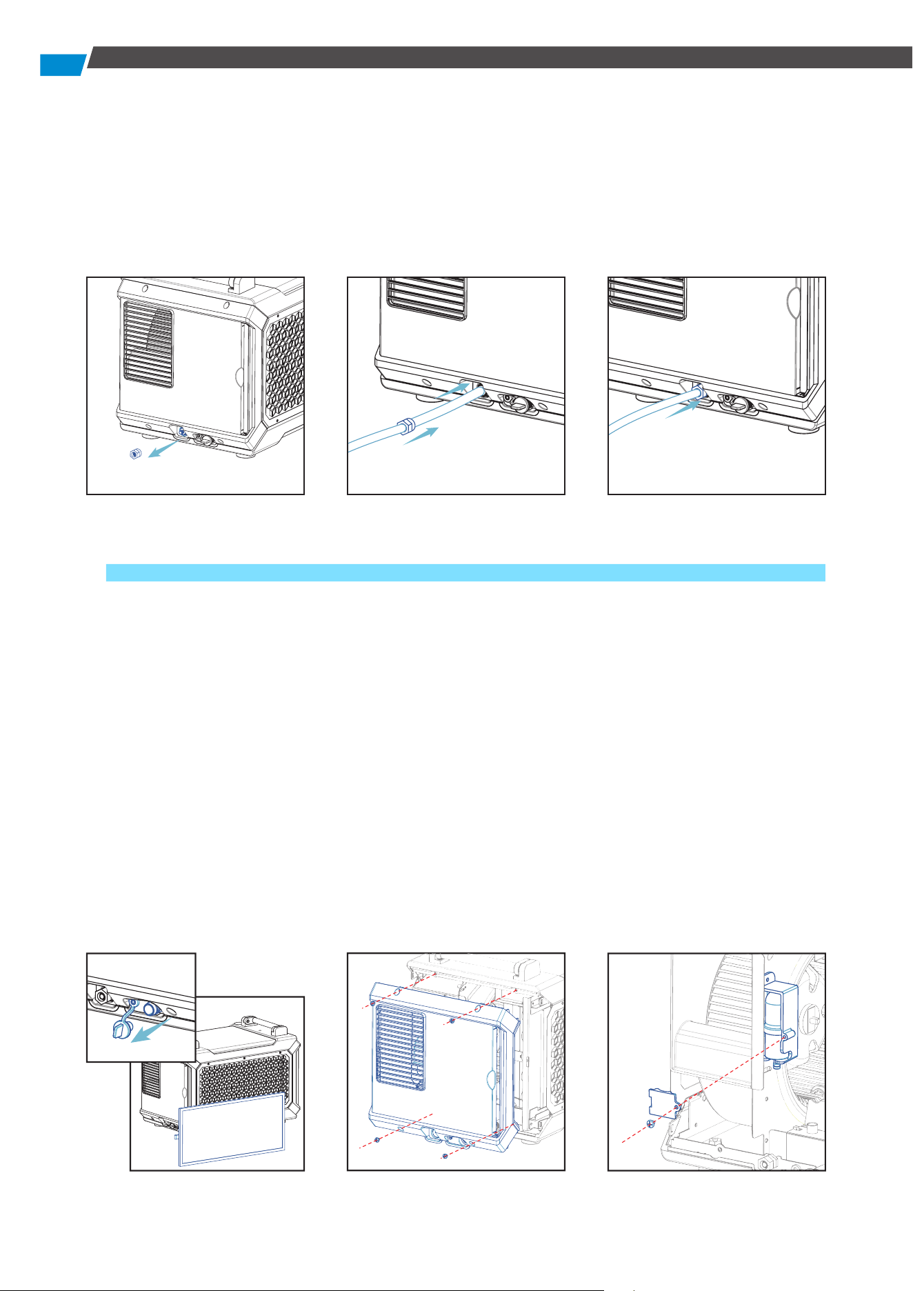
6. Drainage Function
When Using Gravity Drain:
1) Disconnect the water plug first.
2) Insert the gravity drainage pipe securely before powering on the dehumidifier. Ensure that
the end of the water pipe does not exceed the height of the gravity drain.
3) If the dehumidifier displays the E4 alarm interface and becomes unresponsive to other
buttons, except the power button, check for blockages or bends in the drain pipe.
4) Clear any foreign objects from the water pipe to ensure proper drainage and normal
operation of the unit.
When Using the Water Pump:
1) Close the gravity drain with a water plug.
2) Loosen the nut on the water pump drain connection, thread the water hose through the
unscrewed nut, insert it into the water pump drain connection, and tighten.
3) Press and hold the DRAIN button for 3 seconds. The dehumidifier will beep, and the water
pump mode icon will display on the main interface.
8
4) In water pump mode, press the DRAIN button briefly to pump out water for 28 seconds.
5) If an E4 alarm occurs, check for blockages or bends in the water pump's drain pipe.
6) Clear any foreign objects from the water pipes to ensure proper functioning. Resolve the E4
alarm or deactivate the water pump function. Using gravity drainage will allow the machine
to operate normally.
Replacing a Defective Water Pump:
If an E4 alarm occurs during water pump drainage, address the issue by removing any foreign
objects from the water pipe and ensuring it is unblocked. If the E4 error persists and the
appliance operates normally with gravity drainage, the water pump is likely damaged and
requires replacement.
1) Pull out the filter and water plug, and empty the water in the drip tray.
2) Use a Phillips screwdriver to loosen the 4 screws on the air flap, and remove the side panel to
access the water pump.
3) Loosen 1 screw on the water pump bracket using a Phillips screwdriver.
4) Disconnect the water hose and docking cable from the water pump to remove it.
5) Install the new water pump following the steps above.
9
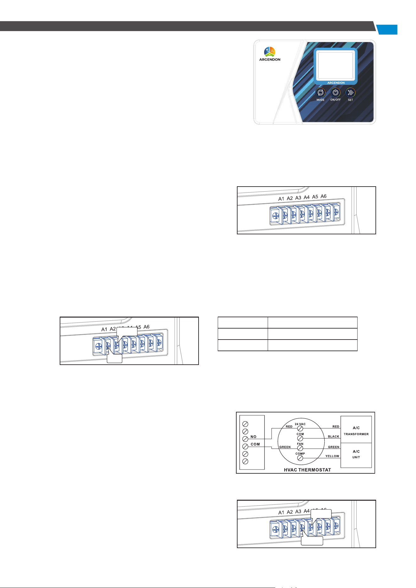
7. Optional Remote Controller
This dehumidifier supports remote control through
a dedicated external controller, connected to the
dehumidifier via a network cable, enabling you to manage
the unit remotely.
The remote controller is especially useful when the
dehumidifier is located in a hard-to-access area, allowing
convenient monitoring.
8. A1-A6 Functions
This model is equipped with A1-A6 external functions, providing enhanced versatility. Below are
the terminal function details:
• Terminal Function Version:
A1 - NO: Normally Open
A2 - COM: Common port
A3 - ON-D: External input (24 V AC/DC)
A4 - COM: External input (24 V AC/DC)
A5 - FLOAT: External low voltage float switch or water
sensor (use normally open switch)
A6 - FLOAT: External low voltage float switch or water
sensor (use normally open switch)
• Auxiliary Relay Operation:
For coordinated fan operation with the central heating/cooling system, the UNIT A1-A2 features
a relay. The COM and NO relay terminals operate as follows:
• Common Uses:
Assuming standard thermostat wiring colors:
Energize the A/C Central Fan During Dehumidifier Fan Operation:
1) Attach a second Green wire to the FAN terminal
on the thermostat.
2) Connect the new Green wire to the COM terminal
on the UNIT.
3) Run a wire from the Red terminal on the
thermostat to the NO (Normally Open) terminal
on the UNIT.
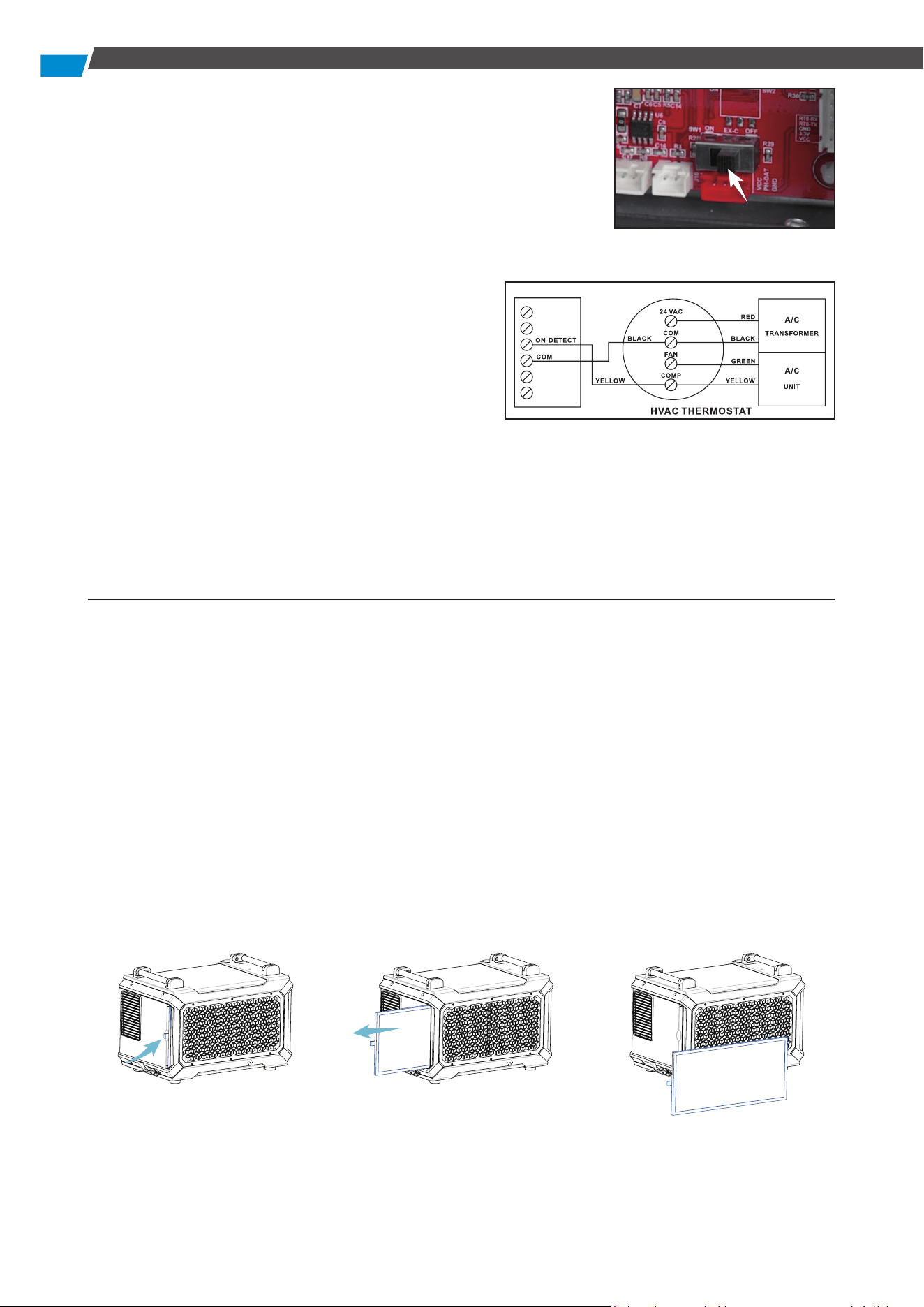
• Dehumidifier Lock-On A/C Sensor Feature:
Automatically activate the dehumidifier when the air
conditioner runs.
When using A3-A4 function, first to open the machine
FAN COM to NO
ON CONNEC TED
OFF OPEN
NO
COM
ON-D
COM
10
Maintenance
WARNING: Always unplug the unit before performing any maintenance.
• Cleaning the Machine Body:
Use a soft damp cloth to clean the exterior. Do not use soap or solvents.
• Coil Maintenance:
Once per year, clean the coils with an approved coil cleaner. Use a self-rinsing, foaming cleaner
such as WEB® Coil Cleaner.
• Cleaning the Filter:
1. Pinch the filter ring and pull out the filter.
2. Clean the filter mesh by vacuuming or washing with warm water (no soap or solvents).
3. After cleaning, place it in a cool area to dry and then reinsert it into the machine.
• Dehumidifier Storage:
To store the unit for an extended period:
1. Turn off the unit and allow it to dry.
2. Wrap and secure the power cord.
3. Store in a clean, dry space.
cover board will switch the motherboard, to the position of
“ON”.
• Activate Dehumidification When the A/C is Running
To enable the Lock-On dehumidifier function, follow these
steps using a voltmeter to ensure correct wiring from the A/C
transformer:
1. Connect the common wire from the existing A/C
transformer (usually Black) to the "COM" sensor
terminal between "ON-D" on the unit.
● Tip: Identify the common wire from the A/C
transformer reading 0 volts between it and the
Yellow air conditioning call for cooling wire. An
incorrect wire will yield a 20 V to 28 V reading.
2. Add another Yellow wire to the thermostat Yellow terminal and run it to the "ON-D" sensor
terminal on the unit.
Note: A5-A6 functions serve as external water pump functions. If these two interfaces remain
continuously connected for 14 seconds, the machine detects an E4 error, causing the unit to
stop. Resolve the E4 error by restarting the unit.
11
Error Code Guide
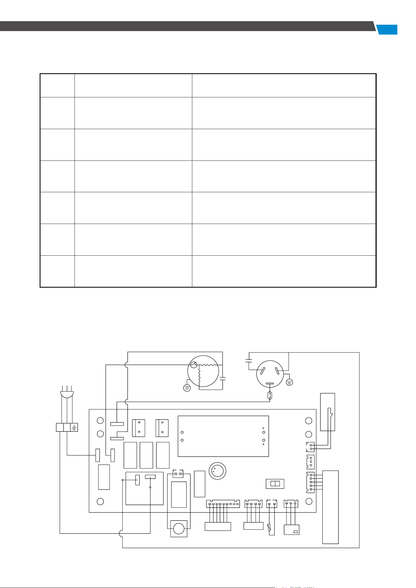
Circuit Diagram
Error
code
Problem Solution
E1
Humidity sensor failure Replace the humidity sensor.
LO
Ambient temperature
≤ 36 °F (2 °C)
Automatically recovers when the ambient
temperature is detected > 36 °F (2 °C).
HI
Ambient temperature
≥ 104 °F (39 °C)
Automatically recovers when the ambient
temperature is detected to be < 104 °F (39 °C).
E3
Defrost failure Check for leaks.
E4
Drainage failure
Check the drain for blockage.
Check the water pipes for damage.
E5
Coil temperature sensor failure
Check for leaks. If no leaks are found, check the
sensor for defects.
DRAIN
HUMIDITY SENSOR
TEMP.SENSOR
Display
WATERLEVEL
WH
WL
Central control switch
ON EX-C OFF
L
N
NO
COM
N
N
N
IN-FEN
EX-FEN
N
L
PROTECTOR
COMPRESSOR
RC
RC
YEL
YEL
BRW
BLU
Network connection
A1
A6
PUMP

12
LIMITED WARRANTY
This limited warranty becomes effective from the date of purchase. Argendon Solutions Inc.
assures the original purchaser that this product is devoid of manufacturing defects in material or
workmanship throughout the specified limited warranty periods:
● Six (6) Months Parts and Labor: This covers replacement parts or unit shipment charges.
● One (1) Year Parts and Labor: Excluding the shipment charge to send the defective product for
repair or replacement.
● Three (3) Years Parts and Labor on Refrigeration System ONLY (Compressor, Condenser, and
Evaporator): Transportation cost not included.
● Five (5) Years Parts on Refrigeration System ONLY (Compressor, Condenser, and Evaporator):
Transportation cost not included.
This limited warranty applies exclusively to products purchased from the manufacturer or an
authorized Argendon dealer and must be operated, installed, and maintained in accordance with
the instructions provided in this user guide. In-home service during or after the warranty period
will not be provided by Argendon Solutions Inc. The purchaser may incur shipping charges to return
the product to the manufacturer for service.
For warranty service, the purchaser must contact Argendon at 888-770-8483 or
sales@argendon.
com
. A proof of purchase or order number is mandatory to receive warranty service. During the
applicable warranty period, Argendon reserves the right to repair or replace the product at its
sole discretion. IMPORTANT NOTICE: Please keep the item's packaging in case warranty service is
needed. If the product is sent for repair without explicit guidance from our customer service team,
Argendon will not assume responsibility for any associated repair costs.
LIMITED WARRANTY EXCLUSIONS
This limited warranty covers manufacturing defects in materials or workmanship encountered
during normal household, commercial, or non-commercial use of this product. However, it does
not extend to the following:
● Misuse: Any damage occurring due to uses this product is not intended for.
● Unauthorized Modification: Damage caused by unauthorized modification or alteration of the
product.
● Cosmetic Damage: This includes scratches, dents, chips, and other damage to the product's
finishes.
● External Factors: Damage resulting from abuse, misuse, pest infestation, accidents, fires,
floods, or other natural disasters.
● Electrical Issues: Damage caused by incorrect electrical line current, voltage, fluctuations, and
surges.
● Improper Maintenance: Damage resulting from a failure to perform proper maintenance of
the product.
Note: The use of this product in a spa or a room with an OUTDOOR POOL will invalidate or void the
limited warranty.

If you have any ques�ons, please feel free to contact us at 888-770-8483.
WARRANTY REGISTRATION CARD
ORDER NUMBER:
MODEL:
SERIAL #:
INSTALLER: INSTALLATION DATE:
NAME:
ADDRESS:
CITY: STATE: ZIP:
PHONE #: EMAIL:
Return To: ARGENDON Solutions


ARGENDON Solutions Inc.
Add: 14752 Yorba Ct, Chino, CA 91710 US
Tel: 888-770-8483
E-mail: sales@argendon.com