28WM7145
2
28WM7145 REV1.0
REGISTER YOUR NEW PURCHASE online!
Thank you for purchasing our product. Please take a moment to
visit tsicustomerservice.com to register your new purchase:
Gracias por adquirir nuestro producto. Tómese un momento para visitar
tsicustomerservice.com y registrar su nueva adquisición:
INSCRIRE VOTRE NOUVEL ACHAT
When registering your product, be sure to sign up for our updates to receive important
service information and helpful tips. We value your privacy and will never share your
personal information with other organizations. The information you submit is used only for
providing product related services to you.
Si vous n’êtes pas en mesure d’effectuer l’enregistrement, conservez votre preuve d’achat
pour le remplacement de pièces. Cuando registre su producto, asegúrese de suscribirse
para recibir actualizaciones importantes sobre el servicio y consejos útiles. Valoramos su
privacidad y no compartiremos su información personal con otras organizaciones. La
información que envíe se usará solo para proporcionarle servicios relacionados con el
producto.
DEPENDABLE CUSTOMER SERVICE • ATENCIÓN AL CLIENTE CONFIABLE FIABLE
Questions?
|
¿Tiene preguntas?
Call customer service Monday to Friday 8:30 am – 5:30 pm EST.
Llame al servicio de atención al cliente. De lunes a viernes de 8:30 a.m. a 5:30 p.m.
1-866-661-1218
Login
New Registration
Product
Manuals
FAQs Help Videos
Manufacturer
Warranty
Retailers
Returns
Order
Tracking
log in >
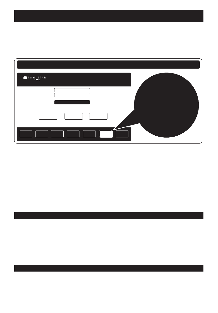
Customer Service Portal
Twin-Star Customer Service online resource to Order Parts,
Product Registration, and to request Product and General Information
DON’T FORGET TO
REGISTER YOUR PRODUCT
ONLINE TO RECEIVE SPECIAL
OFFERS, TIPS AND MORE!
NO OLVIDE REGISTRAR SU PRODUCTO EN LÍNEA
PARA RECIBIR OFERTAS ESPECIALES,
CONSEJOS Y MÁS!
tsicustomerservice.com
Product
Registration

3
28WM7145 REV1.0
PRODUCT DETAILS AND NOTES
DETALLES DEL PRODUCTO Y NOTAS
Place of purchase/Lieu de l’achat/Lugar de compra:
Date of purchase/Fecha de compra:
Model #/Número de modelo:
Notes/Notas:
4
28WM7145 REV1.0
SAFETY
INFORMATION
INFORMACIÓN DE
SEGURIDAD
Please read and understand this entire manual before
attempting to assemble, operate or install the product.
WARNING
• Some steps are more easily handled with two adults.
CAUTION
• Before assembly and/or installation, carefully unwrap
all parts.
• Locate and set aside the hardware kit before
discarding packaging.
• Use care when assembling your new product. Take
your time and follow assembly instructions closely.
Lea y comprenda completamente este manual antes de
intentar ensamblar, usar o instalar el
producto.
ADVERTENCIA
• Algunos de los pasos se pueden realizar con mayor
facilidad entre dos adultos.
PRECAUCIÓN
• Antes del ensamblaje y/o instalación, desenvuelva
cuidadosamente todas las piezas.
• Localice y separe el equipo de accesorios antes de
desechar el embalaje.
• Tenga cuidado al ensamblar el nuevo producto. Tómese
su tiempo y siga detenidamente las instrucciones de
ensamblaje.
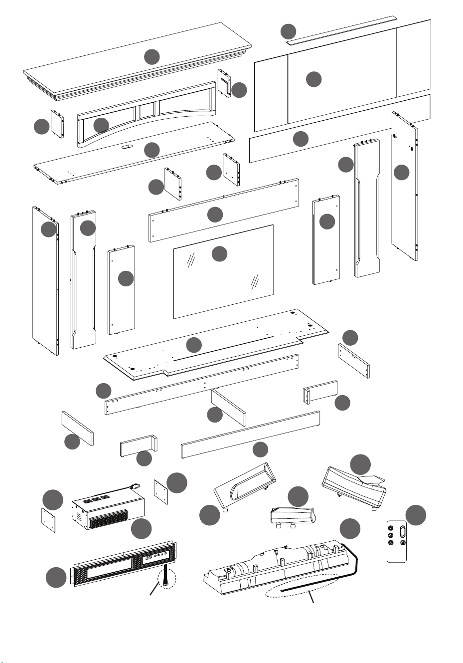
5
28WM7145 REV1.0
EA
EF
EF
EB
EJ
EK
EL
EI
EH
Ember Bed Connection Wire
Cable de conexión del lecho de brasas
Control panel cable
Cable del panel de control
O
G
R
P
Q
A
K
C
B
D
E
N
H
X
W
S
I
Z
J
M
T
U
Y
V
L
F
6
28WM7145 REV1.0
MAXIMUM LOAD
6.8 kg / 15 lb
CARGA MÁXIMA
6.8 kg / 15 lb
WARNING
Loads heavier than the maximum weights specied may result in instability causing tip over resulting in death or serious
injury.
PRECAUCIÓN
Cargas mayores que los pesos máximos especicados puede generar inestabilidad y, en consecuencia, desplomes
que pueden causar la muerte o lesiones graves.
7
28WM7145 REV1.0
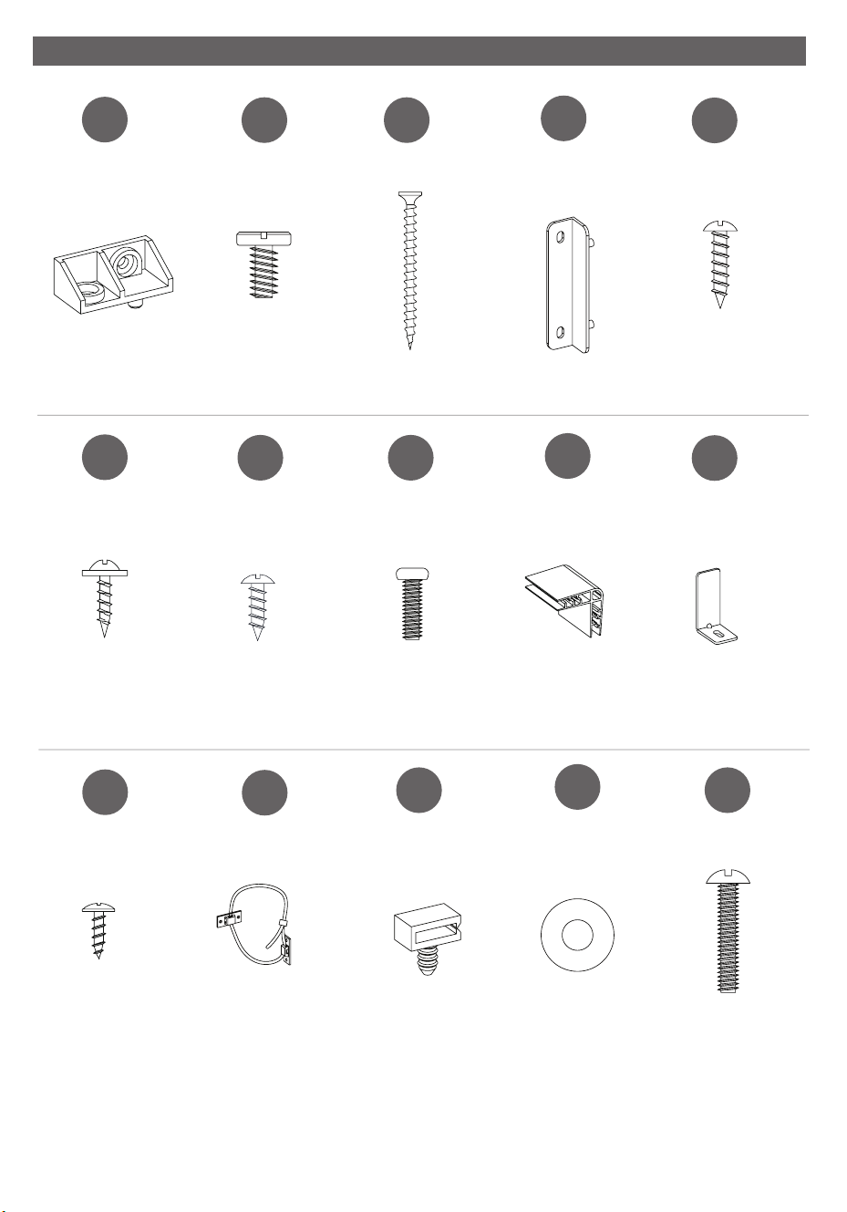
HARDWARE/FERRETERÍA
[x18]
[x16]
[x2]
AA
FF
KK
BB
GG
LL
CC
HH
DD
II
EE
JJ
PH-PCBXXX005
[x40]
[x9]
[x1]
[x8]
[x4]
[x2]
[x2]
[x4]
[x2]
Ø6.3x12mm
PH-BLTBLK002
PH-SCRBLK013
Ø3.5x12mm
PH-BLKBLT013
Ø4x12mm
PH-SCRBLK006
PH-SCRBLK007
PH-BLTBLK001
PH-28WM7145-KK
PH-28WM7145-DD
Ø4x50mm
Ø3x12mm
Ø6.3x32mm
Ø4x12mm
Ø3x16mm
PH-28WM7145-EE
PH-28WM7145-II
PH-BKTBLK007
PH-BKTWHT003
PH-WMCBLK004
MM OO
[x3] [x8]
[x8]
NN
PH-WSRBLK002
Ø16mm

8
28WM7145 REV1.0
INSTALLED REPLACEMENT PARTS 28WM7145
PIEZAS DE REPUESTO INSTALADAS 28WM7145
PP
QQ
RR
[x40]
[x6]
[x2]
PH-GLDBRW001
PH-PLTBLK001
PH-THRZNC001
9
28WM7145 REV1.0
ATTENTION: Follow instructions in the order they are given below. This will ensure that your
product is properly assembled. To reduce the risk of damage to your furniture, please lay
down a blanket, cloth, or cardboard on the oor prior to assembly.
ATTENTION: Suivre les instructions dans l’ordre donné ci-dessous. Cela vous assurera
d’assembler correctement le produit. Para reducir el riesgo de daño a sus muebles, por
favor coloque una manta, tela o cartón en el suelo antes del montaje.
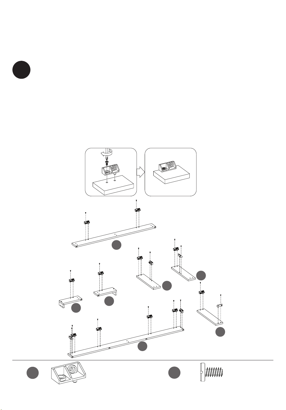
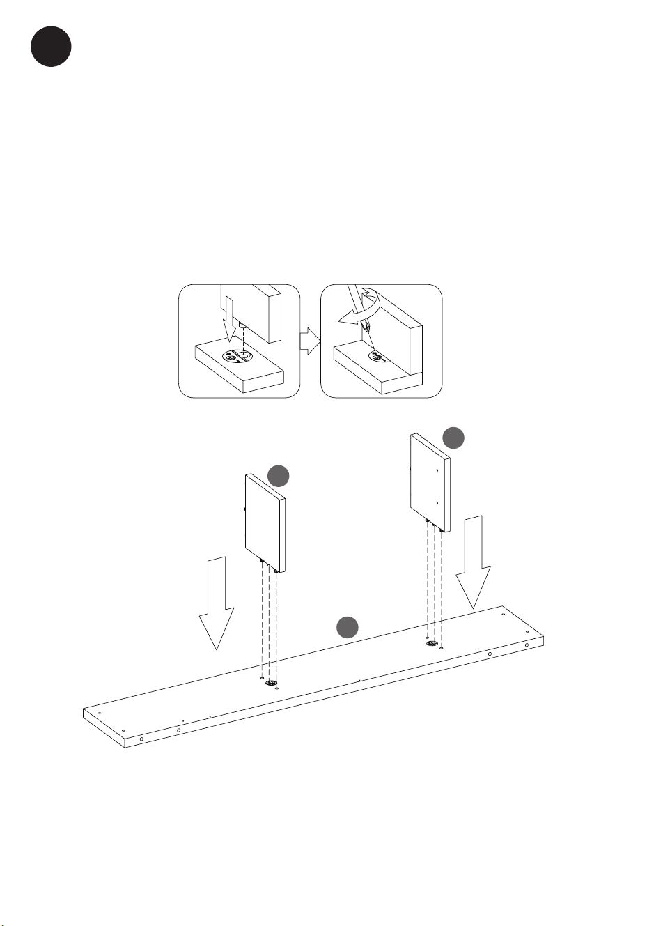
1
Preparing the Base Rails
• Attach the Plastic Connector Blocks (AA) to the Base Front Rail (J) with Bolts (BB).
• Repeat for Base Back Rail (C), Base Left and Right Rails (D and B), all Base Rails for
decorative front (E and F) and Base center support Rail (H).
Preparación de los rieles de la base
• Fije los bloques de conectores de plástico (AA) al riel delantero de la base (J) con
pernos (BB).
•
Repita el procedimiento para el Riel Trasero de la Base (C), los Rieles
Izquierdo y Derecho de la Base (D y B), todos los Rieles de la Base para el
frente decorativo (E y F) y el Riel de Soporte Central de la Base (H).
J
E
F
H
B
D
C
BB
AA
[x16]
[x16]
10
28WM7145 REV1.0
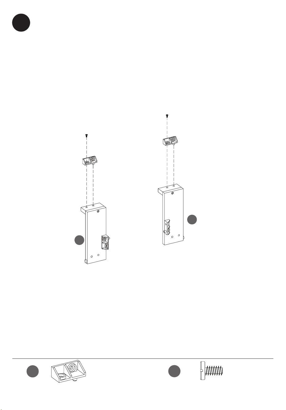
2
Preparing the Base Rails
• Attach the Plastic Connector Blocks (AA) to Base Rails for decorative front (E and F)
with Bolts (BB).
Preparación de los rieles de la base
• Fije los Bloques Conectores de Plástico (AA) a los Rieles de la Base para el frente
decorativo (E y F) con los Pernos (BB).
E
F
BB
AA
[x2]
[x2]
11
28WM7145 REV1.0
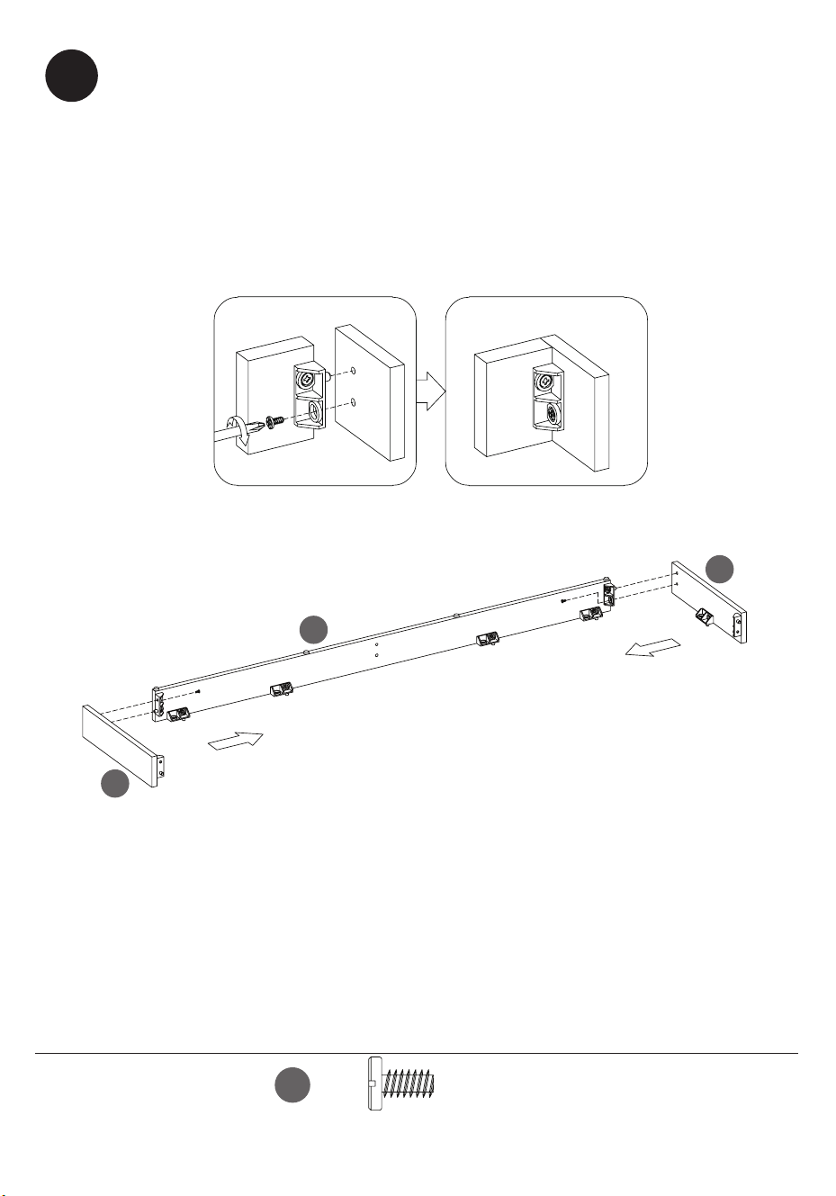
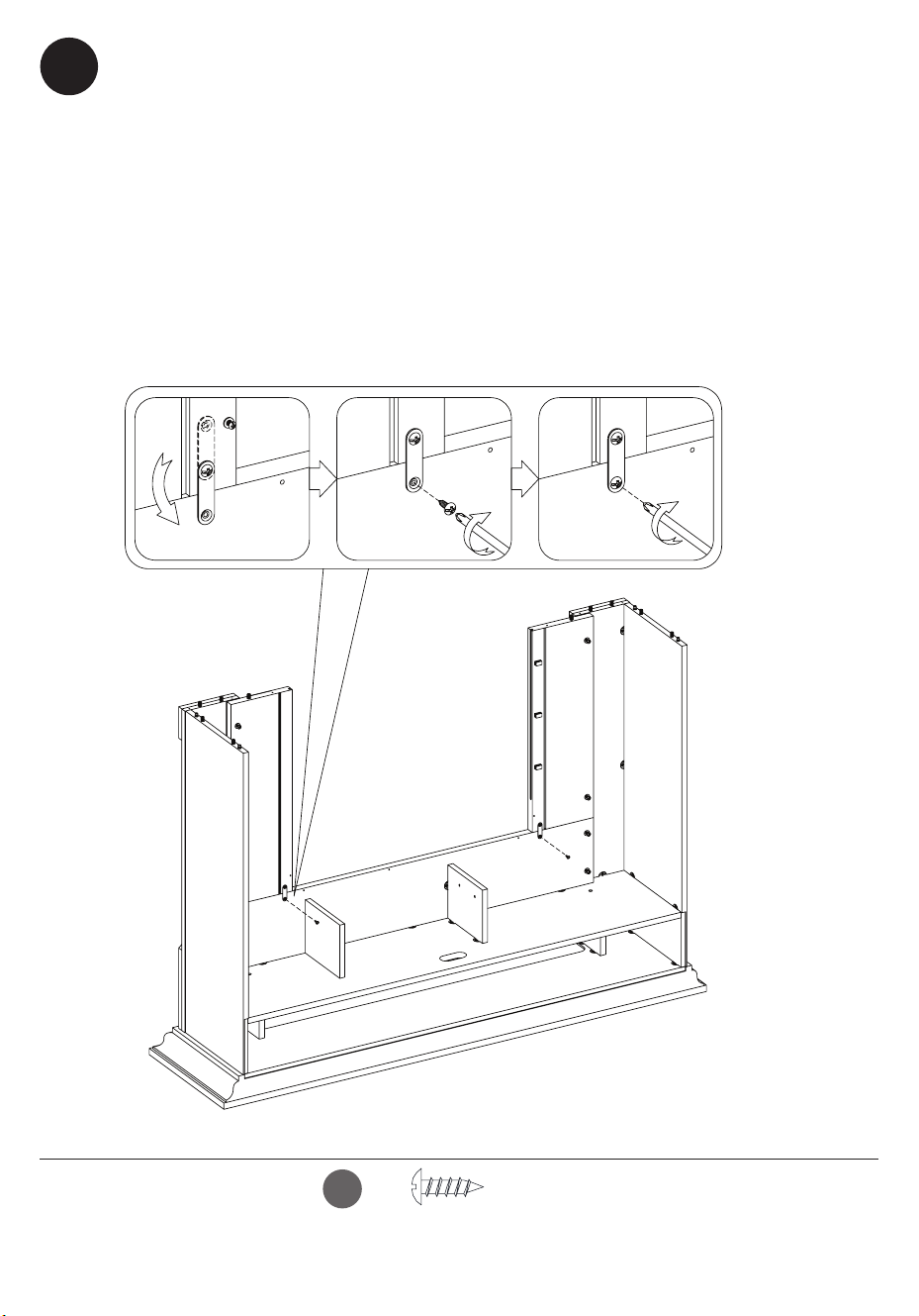
3
Connecting the Bottom Rails
• Attach Base Left Rail (D) and Base Right Rail (B) to the Base Back Rail (C) by
inserting the Bolts (BB) through the Plastic Connector Blocks (AA).
• Tighten with a Phillips screwdriver as shown.
Ensamblaje de los rieles inferiores
• Fije el riel izquierdo de la base (D) y el riel derecho de la base (B) al
riel posterior de la base (C) colocando los pernos (BB) a través de los
bloques conectores de plástico (AA).
• Apriete con un destornillador Phillips, como se muestra aquí.
B
D
C
BB
[x2]
12
28WM7145 REV1.0
H
D
C
B
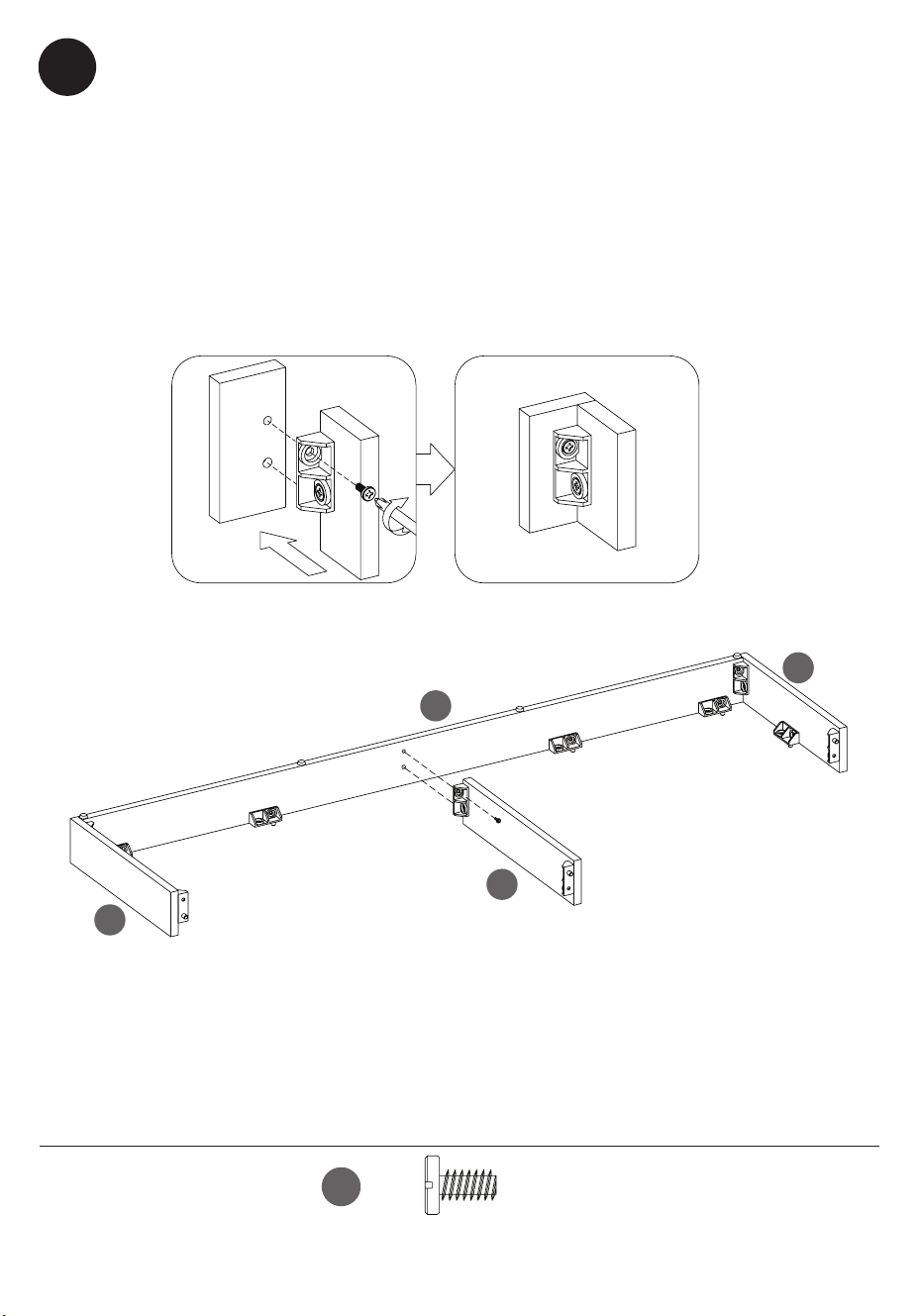
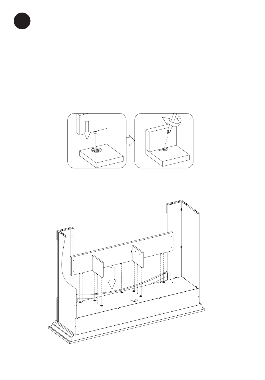
4
Connecting the Base Center Support Rail
• Attach Base center support Rail (H) to the Base Back Rail (C) by inserting the Bolts
(BB) through the Plastic Connector Blocks (AA)
• Tighten with a Phillips screwdriver as shown.
Conexión del Riel de Soporte Central de la Base
• Fije el Riel de Soporte Central de la Base (H) al Riel Trasero de la Base (C)
insertando los Pernos (BB) a través de los Bloques Conectores de Plástico (AA).
• Apriete con un destornillador Phillips, como se muestra aquí.
BB
[x1]
13
28WM7145 REV1.0
E
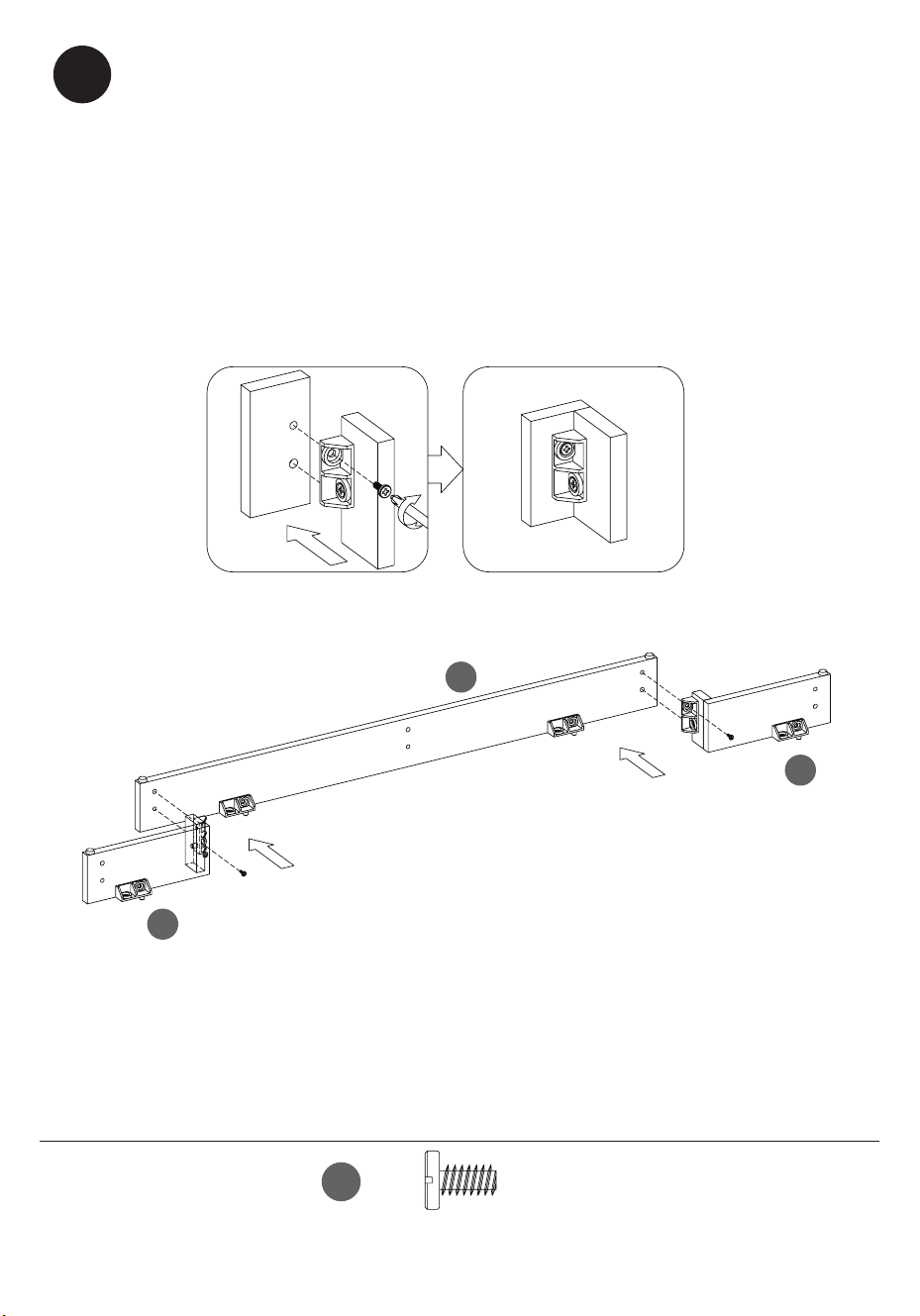
5
Connecting the Bottom Rails
• Attach Base Rails for decorative front (E and F) to the Base Front Rail (J) by
inserting the Bolts (BB) through the Plastic Connector Blocks (AA).
• Tighten with a Phillips screwdriver as shown.
F
J
BB
[x2]
Ensamblaje de los rieles inferiores
• Fije los Carriles Decorativos Laterales Pequeños Izquierdo y Derecho de la Base
(F y E) al Carril Frontal de la Base (J) insertando los Pernos (BB) a través de los
Bloques de Conexión de Plástico (AA).
• Apriete con un destornillador Phillips, como se muestra aquí.
14
28WM7145 REV1.0
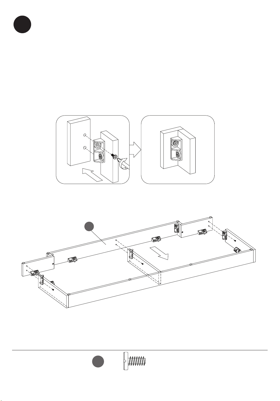
6
Connecting the Bottom Rails
• Attach Base Front Rails assembly to the Base Side and Back Rails assembly
by inserting the Bolts (BB) through the Plastic Connector Blocks (AA).
• Tighten with a Phillips screwdriver as shown.
J
BB
[x3]
Ensamblaje de los rieles inferiores
• Fije el conjunto de Carriles Frontales de la Base al conjunto de Carriles Laterales y
Traseros de la base insertando los Pernos (BB) a través de los Bloques de Conexión
de Plástico (AA).
• Apriete con un destornillador Phillips, como se muestra aquí.
15
28WM7145 REV1.0
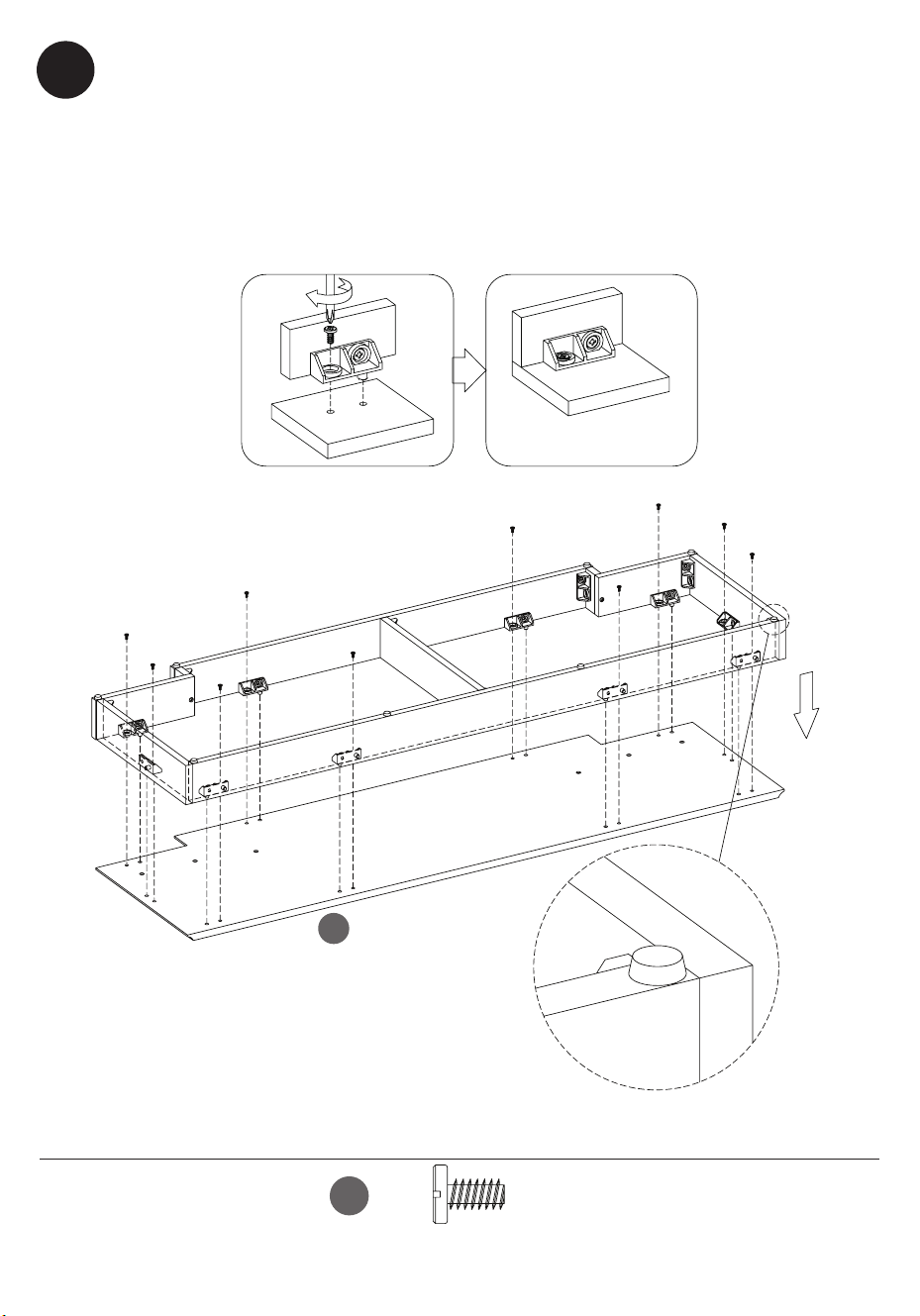
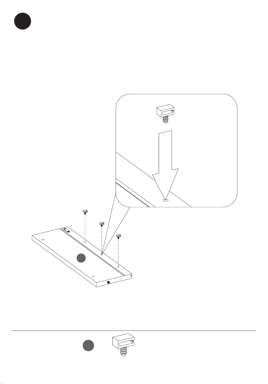
7
Attaching the Base to the Bottom Rails Assembly
• Insert the Bolts (BB) through the holes in the Plastic Connector Blocks (AA)
to attach the Base (A) to the Bottom Rails Assembly.
Fijación de la Base al Conjunto de Carriles Inferiores
• Inserte los pernos (BB) a través de los oricios en los bloques de conectores
de plástico (AA) para unir la base (A) al ensamblaje de rieles inferiores.
A
BB
[x10]
16
28WM7145 REV1.0
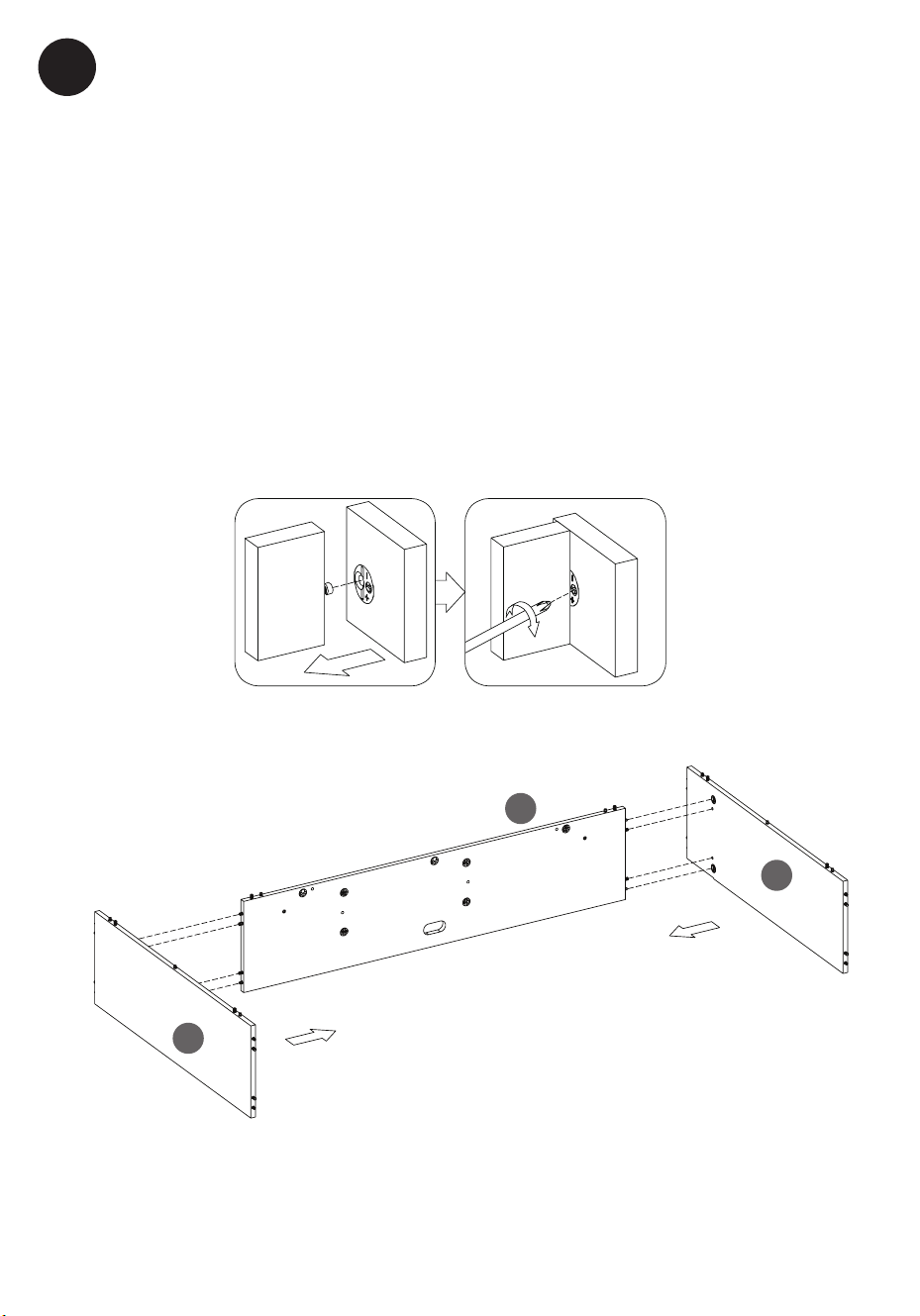
8
Constructing the center assembly
• Align the Fixed Shelf (K) between the Left and Right Side Panels (M and L).
Push together, inserting the pre-installed screws on the Fixed Shelf (K) into
the holes on the Left and Right Side Panels (M and L). After inserting the
screws into the holes, tighten the fasteners in the Left and Right Side Panels
(M and L) using a Phillips Screwdriver as shown.
Fijación del conjunto central
• Alinee el Estante Fijo (K) entre los Paneles Laterales Izquierdo y Derecho (M
y L). Empuje, insertando los tornillos preinstalados en el Estante Fijo (K) en
los oricios de los Paneles Laterales Izquierdo y Derecho (M y L). Después
de insertar los tornillos en los oricios, apriete los sujetadores en los Paneles
Laterales Izquierdo y Derecho (M y L) usando un Destornillador Phillips, tal
como se muestra.
K
M
L
17
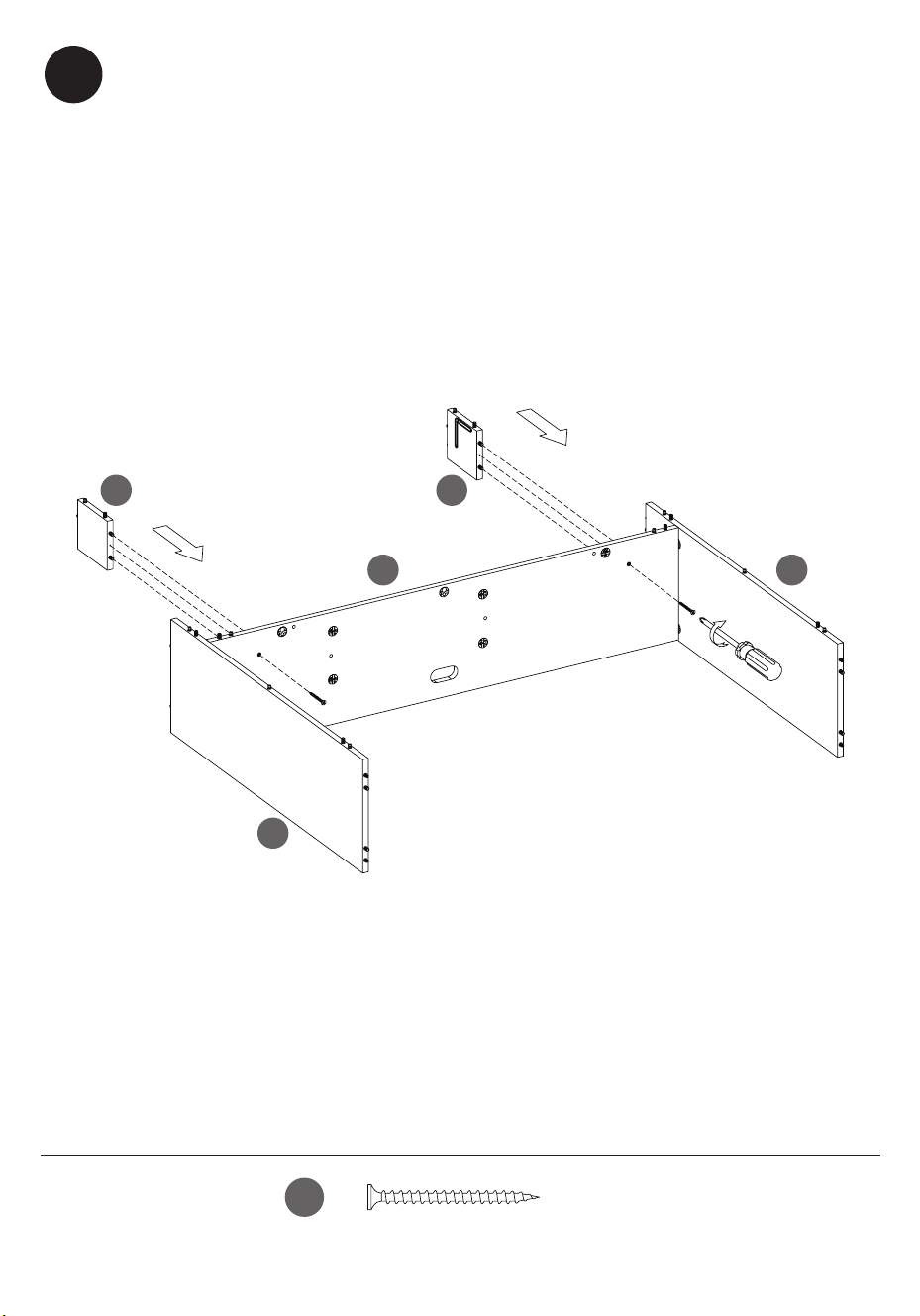
28WM7145 REV1.0
M
L
O P
K
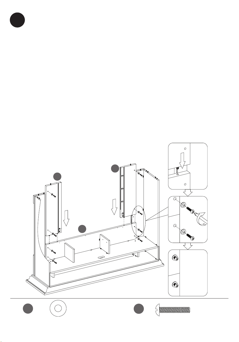
CC
[x2]
Attaching the Side Partitions
• Attach the Left Upper Partition (O) and Right Upper Partition (P) to the
Fixed Shelf (K) by inserting the Bolts (CC).
• Tighten with a Phillips screwdriver as shown.
Fijación de los Tabiques Laterales
• Fije el Tabique Superior Izquierdo (O) y el Tabique Superior Derecho
(P) al Estante Fijo (K) insertando los Pernos (CC).
• Apriete con un destornillador Phillips, como se muestra aquí.
9
18
28WM7145 REV1.0
Q
R
10
Attaching the Front Side Panels
• Attach Right Front Side Panel (R) and the Left Front Side Panel (Q) to the
Main Assembly, by aligning the pre-installed hardware on the edges of the
Main Assembly with the pre-drilled holes on the backs of the Right Front
Side Panel (R) and the Left Front Side Panel (Q) as shown.
Fijación de los Paneles Laterales Frontales
• Fije el Panel Frontal Derecho (R) y el Panel Frontal Izquierdo (Q) al Conjunto
Principal, alineando los herrajes preinstalados en los bordes del Conjunto
Principal con los oricios pretaladrados en la parte trasera del Panel Frontal
Derecho (R) y del Panel Frontal Izquierdo (Q) tal como se muestra.
L
M
K
19
28WM7145 REV1.0
DD
EE
[x2]
[x4]
Attaching the Upper Surround Panel
• Attach the Upper Surround Panel (N) to the Main Assembly by attaching
the Barrister Door Hardware (DD) with screws (EE) on both sides as shown.
Fijación del Panel Envolvente Superior
• Fije el Panel Envolvente Superior (N) al Conjunto Principal jando los
herrajes de la puerta Barrister (DD) con Tornillos (EE) en ambos lados, tal
como se muestra.
N
11
20
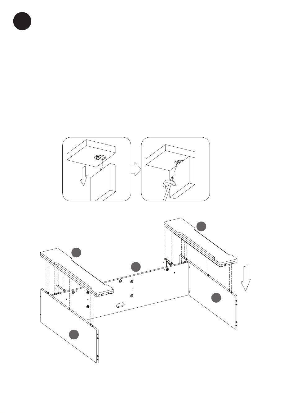
28WM7145 REV1.0
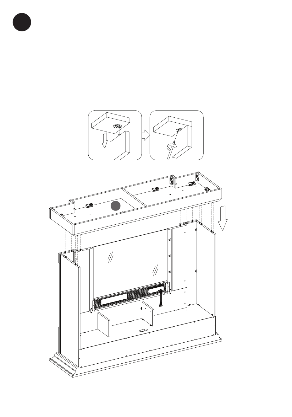
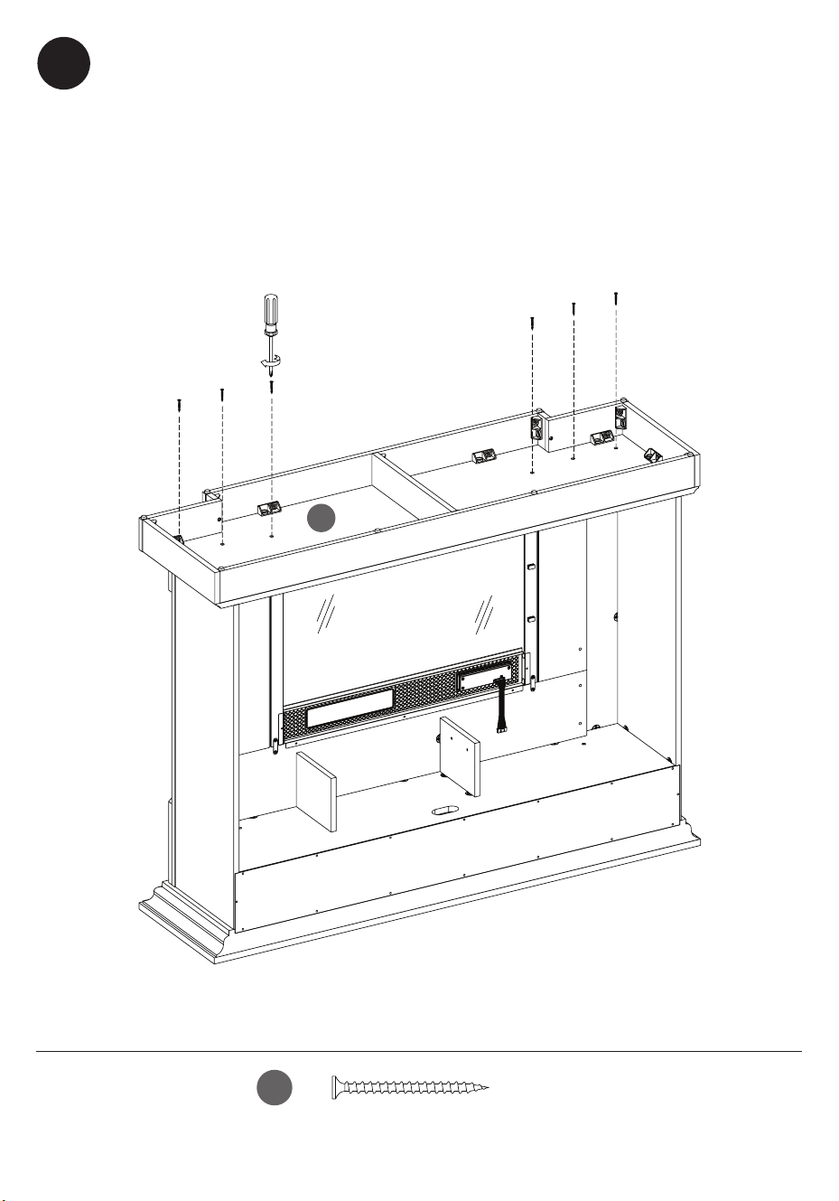
12
Attaching the Main Assembly to the Top Panel
• Attach the Main Assembly to the Top Panel (G), aligning the pre-installed
hardware on the edges of the Main Assembly with the pre-drilled holes in
the Top Panel (G).
• After inserting the screws into the holes, tighten the fasteners, using a Phillips
Screwdriver as shown.
Fijación del Conjunto Principal al Panel Superior
• Fije el Conjunto Principal al Panel Superior (G), alineando los herrajes
preinstalados en los bordes del Conjunto Principal con los oricios
pretaladrados en el Panel Superior (G).
• Después de insertar los tornillos en los oricios, apriete los sujetadores,
utilizando un Destornillador Phillips, tal como se muestra.
G
21
28WM7145 REV1.0
13
S
FF
[x2]
Attaching the Upper Back Panel
• Begin attaching the Upper Back Panel (S), with Screws (FF), using a Phillips
Screwdriver in the two corners as shown.
Fijación del Panel Trasero Superior
• Comience a jar el Panel Trasero Superior (S), con Tornillos (FF), utilizando un
Destornillador Phillips en las dos esquinas, tal como se muestra.
22
28WM7145 REV1.0
FF
[x14]
14
Attaching the Upper Back Panel
• Finish attaching the Upper Back Panel (S), with Screws (FF), using a Phillips
Screwdriver to fasten all the screws, as shown.
Fijación del Panel Trasero Superior
• Termine de jar el Panel Trasero Superior (S) con los Tornillos (FF),
utilizando un Destornillador Phillips para jar todos los tornillos, tal como se
muestra.
23
28WM7145 REV1.0
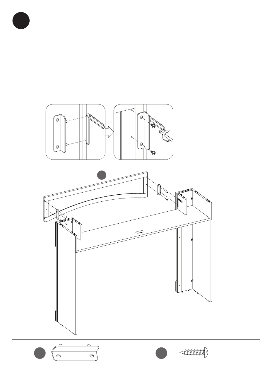
15
W
X
U
Attaching the Support Brackets to the Upper Surround Panel
• Attach the Left and Right Support Brackets (W and X) to the Upper
Surround Panel (U) by aligning the pre-installed hardware on the edges of
the support brackets with the pre-drilled holes on the back of the Upper
Surround Panel and securing with a Phillips screwdriver as shown.
Fijación de los Soportes al Panel Envolvente Superior
• Fije los Soportes Izquierdo y Derecho (W y X) al Panel Envolvente Superior
(U), alineando los herrajes preinstalados en los bordes de los soportes con
los oricios pretaladrados en la parte trasera del Panel Envolvente Superior
y jándolos con un destornillador Phillips, tal como se muestra.
24
28WM7145 REV1.0
16
Attaching the Surround Panel Assembly
• Attach the Surround Panel Assembly to the Main Assembly by aligning the
pre-installed hardware on the edges of the Surround Panel Assembly with
the pre-drilled holes on the underside of the Fixed Shelf and securing with a
Phillips screwdriver as shown.
Fijación del Conjunto del Panel Envolvente
• Fije el Conjunto del Panel Envolvente al Conjunto Principal, alineando los
herrajes preinstalados en los bordes del Conjunto del Panel Envolvente con
los oricios pretaladrados en la parte inferior del Estante Fijo y jándolos
con un destornillador Phillips, tal como se muestra.
25
28WM7145 REV1.0
17
V
Attaching the Wire Clips
•
Insert Wire Clips (MM) into pre-drilled holes in the Right Surround Panel
(V), pushing them in by hand.
Conexión de los sujetadores de cables
•
Inserte los Clips de Alambre (MM) en los oricios pretaladrados del
Panel Envolvente Derecho (V), empujándolos con la mano.
MM
[x3]
26
28WM7145 REV1.0
OO
NN
[x8]
[x8]
T
V
18
Assembling the Inner Surround Panels
• Insert the pre-installed dowels on the Left Surround Panel (T) and Right
Surround Panel (V) into the holes on the Front Surround Panel (U) as shown.
• Attach the Left and Right Surround Panels (T and V) and the Front Surround
Panel (U) to Main Assembly by inserting the Bolts (OO) through Washer
(NN).
Note: Leave all bolts nger tight at this step, so that parts can be adjusted to
t together easily.
Montaje de los Paneles Laterales Interiores
• Inserte los pasadores preinstalados en el Panel Envolvente Izquierdo (T) y el
Panel Envolvente Derecho (V) en los oricios del Panel Envolvente Frontal
(U), tal como se muestra.
• Fije los Paneles Envolventes Izquierdo y Derecho (T y V) y el Panel Envolvente
Frontal (U) al conjunto principal introduciendo los Pernos (OO) a través de
la Arandela (NN).
Nota: ja todos los tornillos apretándolos con los dedos en este paso, de
modo que las piezas se puedan ajustar para encajar fácilmente.
U
27
28WM7145 REV1.0
19
GG
[x2]
Securing the Surround Panels Assembly
• Rotate the pre-attached metal plates.
• Align metal plates with pre-drilled holes and then secure the surround
panels with Screws (GG).
• Tighten with a Phillips screwdriver as shown.
Fijación del Conjunto de Paneles Envolventes
• Gire la placa metálica preinstalada.
• Alinee la plataforma y, a continuación, je los paneles envolventes con un
Tornillo (GG).
• Apriete con un destornillador Phillips, como se muestra aquí.
28
28WM7145 REV1.0
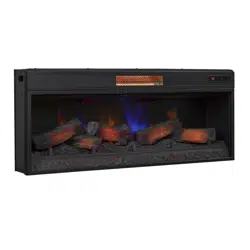
EA
GG
[x5]
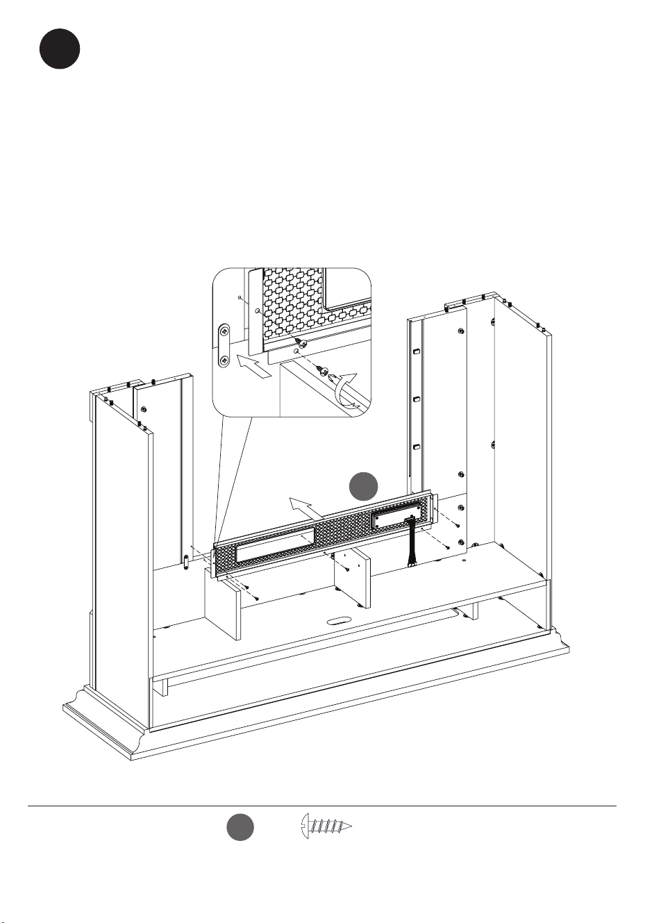
20
Assembling the replace
• Locate the Front Panel with Control Button (EA).
• Using Screws (GG), secure the Front Panel with Control Button (EA) inside
the inner surround assembly as shown.
Ensamblaje de la chimenea
• Ubique el panel delantero con el botón de control (EA).
• Con tornillos (GG), asegure el panel frontal con el botón de control (EA)
dentro del ensamble del marco interior como se muestra.
29
28WM7145 REV1.0
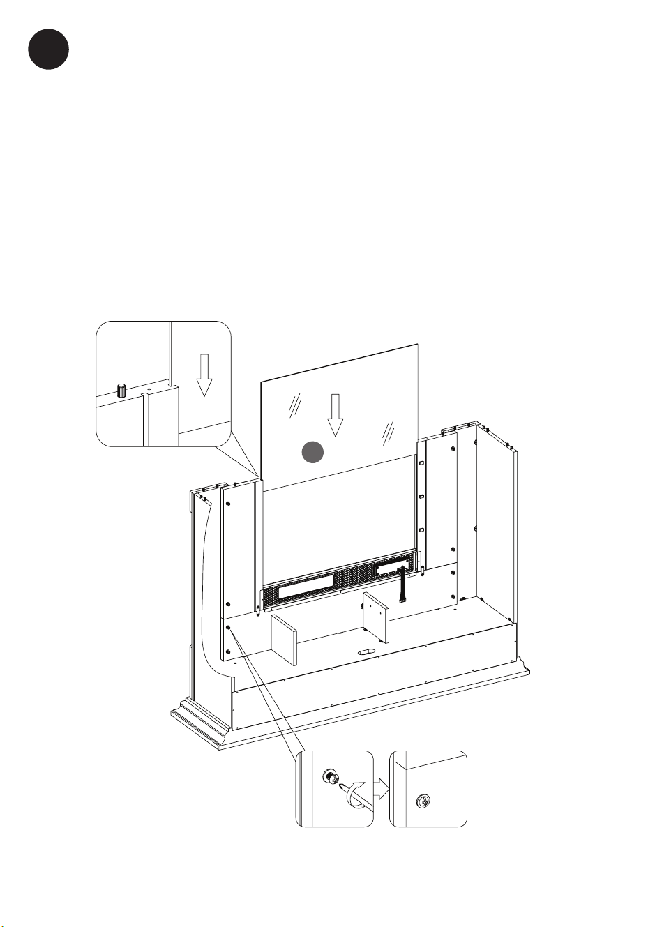
21
Y
Placing the Glass Front
• Locate the Glass (Y).
• Carefully insert the Glass (Y) into the grooves of the surround rails as shown.
Slide all the way in until the glass meets the bottom of the Control Support
Panel.
• Tighten all bolts completely after all parts are aligned.
Colocación del Frente de Cristal
• Localice el Cristal (Y).
• Inserte con cuidado el Cristal (Y) en las ranuras de los carriles envolventes,
tal como se muestra. Deslícelo completamente hasta que el cristal se
encuentre con la parte inferior del Panel de Soporte de Control.
• Ajusta todos los tornillos por completo una vez que todas las piezas estén
bien alineadas.
30
28WM7145 REV1.0
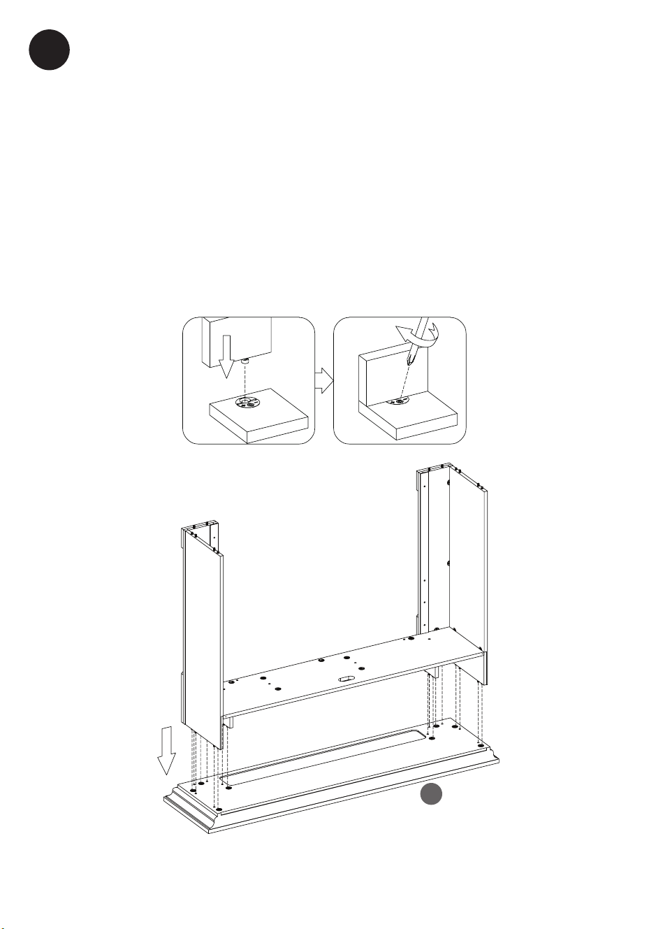
22
A
Attaching the Base
• Locate the Base Assembly.
• Align the pre-installed hardware on the edges of the main assembly with
the pre-drilled holes on the Base (A).
• Securely tighten all screws using a Phillips screwdriver
Conexión de la base
• Ubique el ensamblaje de la base.
• Alinee los herrajes preinstalados en los bordes del conjunto principal con
los oricios pretaladrados en la Base (A).
• Apriete rmemente todos los tornillos con un destornillador Phillips.
31
28WM7145 REV1.0
A
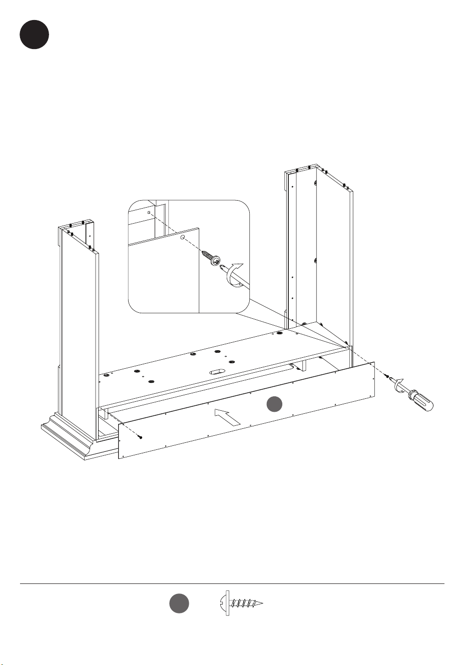
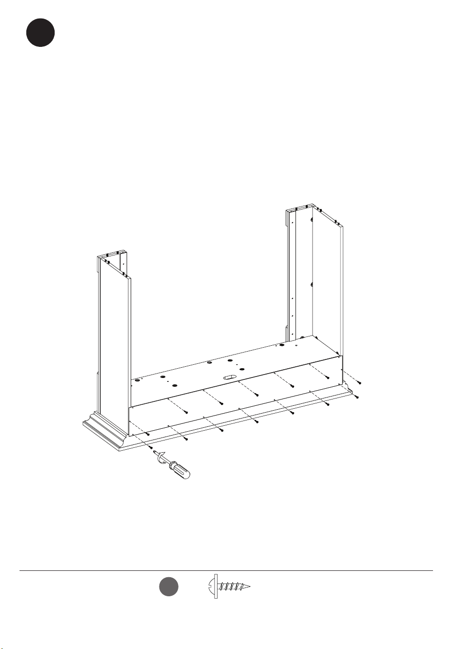
23
Attaching the Base
• Insert Screws (CC) through the Base (A) and into the pre-drilled holes on
the edges of the main assembly as shown.
• Securely tighten all screws using a Phillips screwdriver.
Conexión de la base
• Inserte los Tornillos (CC) a través de la Base (A) y en los oricios
pretaladrados de los bordes del conjunto principal, tal como se muestra.
• Apriete rmemente todos los tornillos con un destornillador Phillips.
CC
[x6]
32
28WM7145 REV1.0
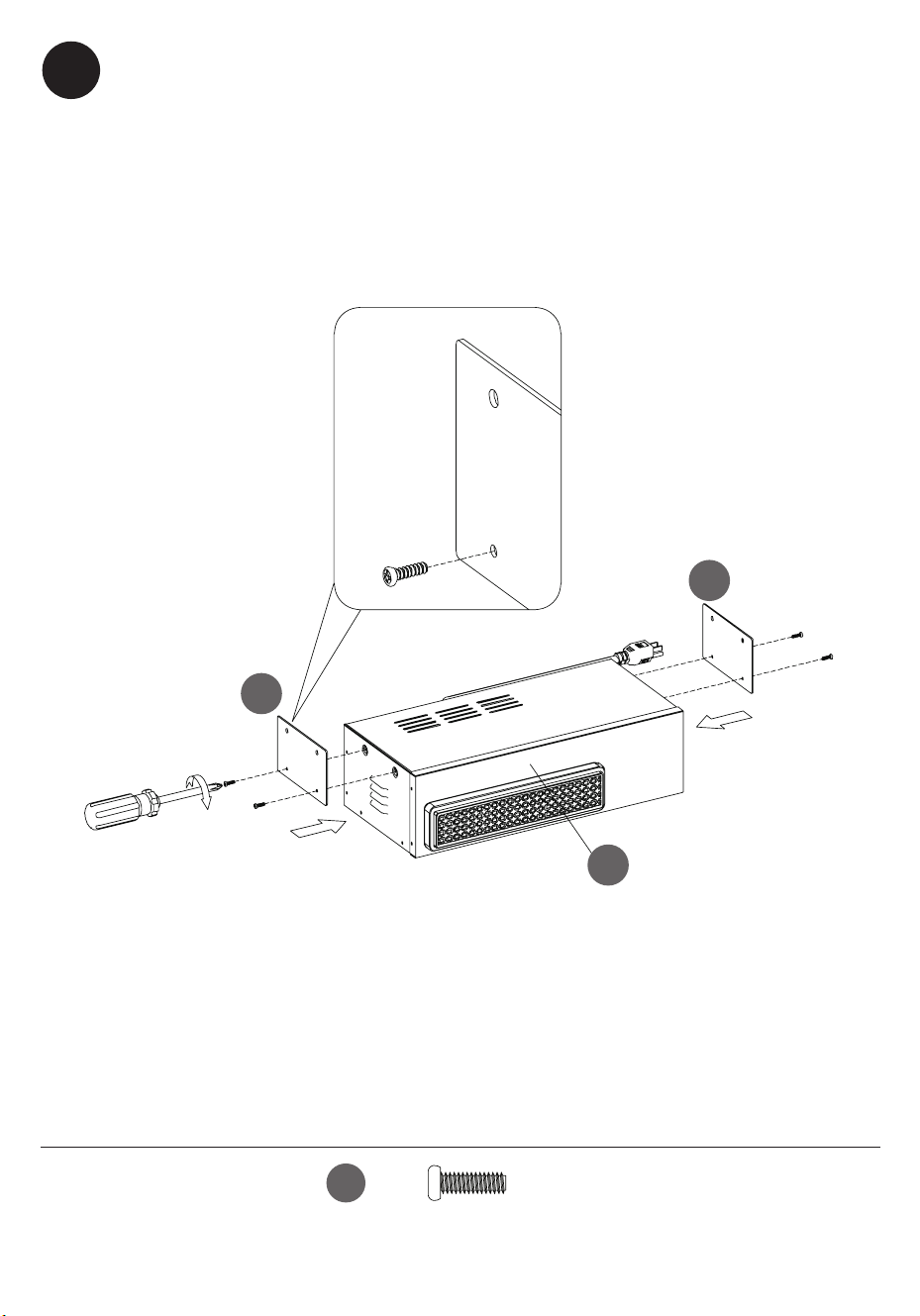
24
HH
[x4]
Attaching the Insert Brackets
• Locate the Brackets (EF) and secure to each side of the Heater Box (EB)
using Bolts (HH).
Colocación de los soportes empotrables
• Ubique los soportes en L (EF) y asegúrelos a cada lado de la caja de
calentador (EB) con pernos (HH), como se muestra.
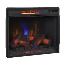
EB
EF
EF
33
28WM7145 REV1.0
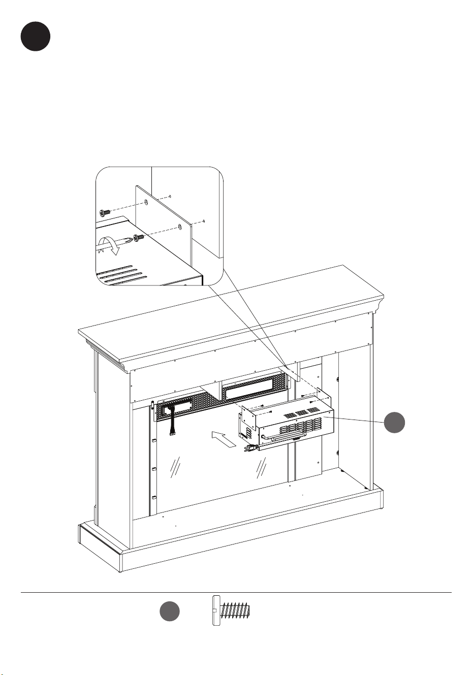
EB
25
Installing the Fireplace Heater Box
• Secure the Heater Box (EB) in place by screwing Bolts (BB) through the
holes in the Brackets (EF) on the Heater Box (EB) and into the Left and Right
Support Brackets.
Instalación del calentador de la chimenea
• Asegure la Caja del Calentador (EB) en su lugar atornillando los
Pernos (BB) a través de los agujeros en los Soportes (EF) en la Caja del
Calentador (EB) y en los Soportes Izquierdo y Derecho.
BB
[x4]
34
28WM7145 REV1.0
26
Assembling the Log Set
• Place the Log Set Middle (EL) into the Ember Bed (EI) as shown.
Ensamblaje del juego de leños
•
Coloque el juego de leños central (EL) en el lecho de brasas (EI), como se
muestra.
EL
EI
35
28WM7145 REV1.0
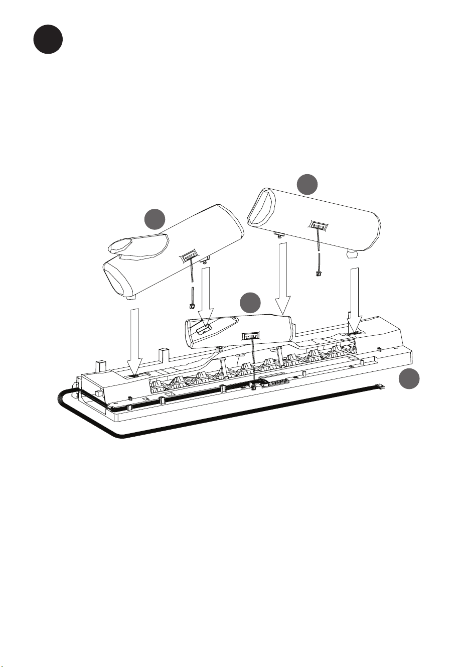
27
Assembling the Log Set
•
Place the Log Set Left (EJ) and Log Set Right (EK) into the Log Set Middle
(EL) and Ember Bed (EI) as shown.
Ensamblaje del juego de leños
•
Coloque el juego de leños izquierdo (EJ) y el juego de leños derecho
(EK) en el juego de leños central (EL) y el lecho de brasas (EI), como se
muestra.
EI
EL
EJ
EK
36
28WM7145 REV1.0
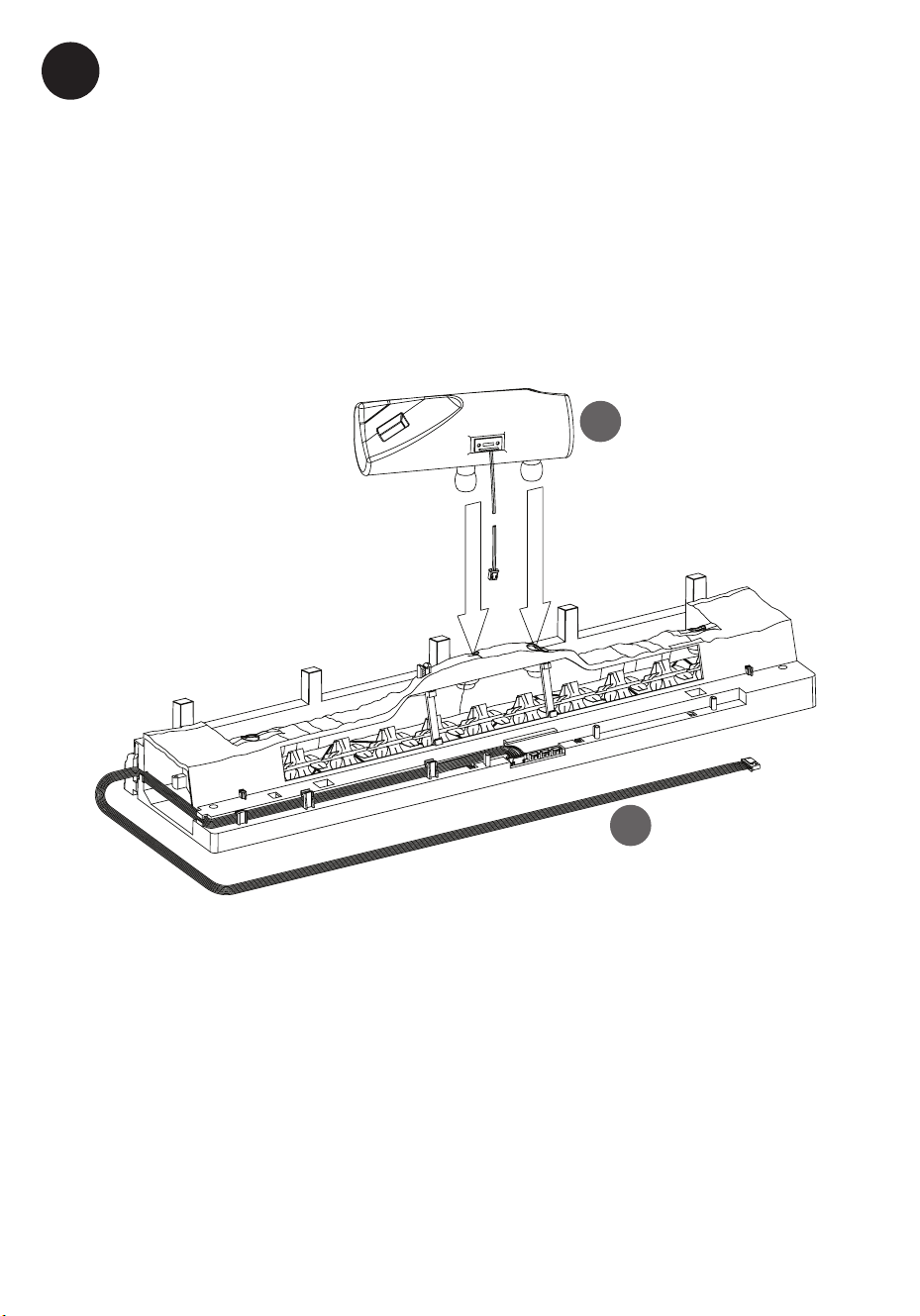
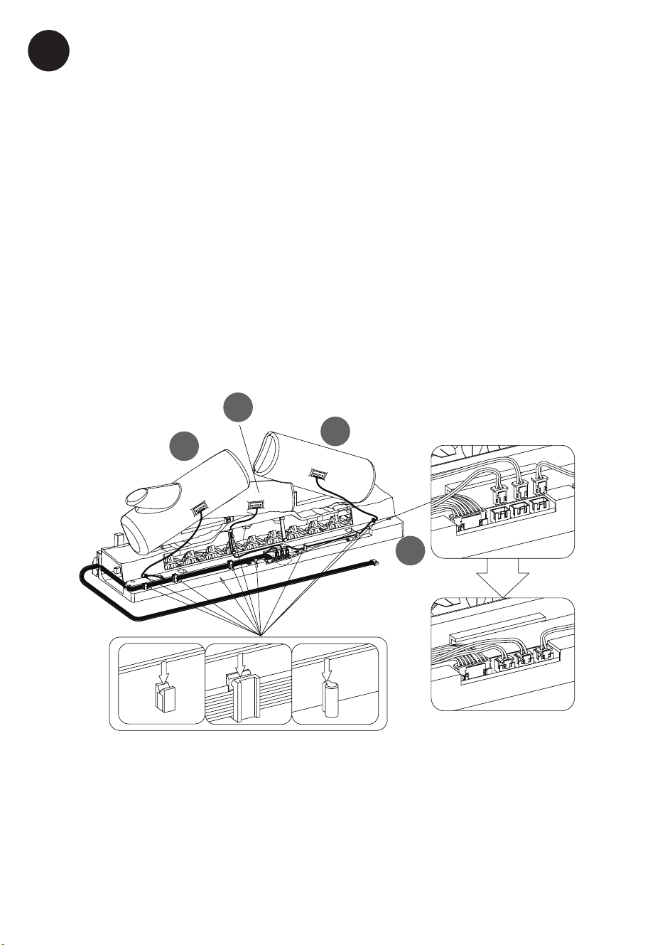
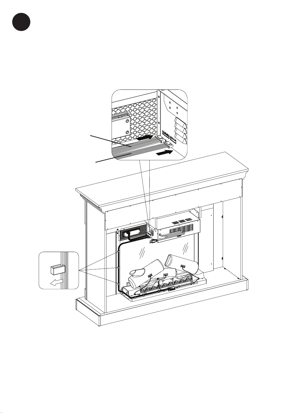
28
Assembling the Log Set
• Route the wires of the Log Set Left (EJ), the Log Set Right (EK) and Log Set
Middle (EL) down the back of the Ember Bed (EI) and into the receiving
tabs to secure in place. Refer to the lower diagram.
• Gently plug the cords from the Log Set Left (EJ), the Log Set Right (EK) and
Log Set Middle (EL) into the ports as shown. Ensure the cords are plugged
in straight.
Ensamblaje del juego de leños
• Oriente los cables del juego de leños izquierdo (EJ), el juego de leños
derecho (EK) y el juego de leños central (EL) hacia la parte posterior del
lecho de brasas (EI) y dentro de las pestañas receptoras para asegurarlos
en su lugar. Consulte el diagrama inferior.
• Enchufe con cuidado los cables del juego de leños izquierdo (EJ), el juego
de leños derecho (EK) y el juego de leños central (EL) en los puertos,
como se muestra. Asegúrese de que los cables estén conectados de forma
recta.
EK
EJ
EL
EI
37
28WM7145 REV1.0
EI
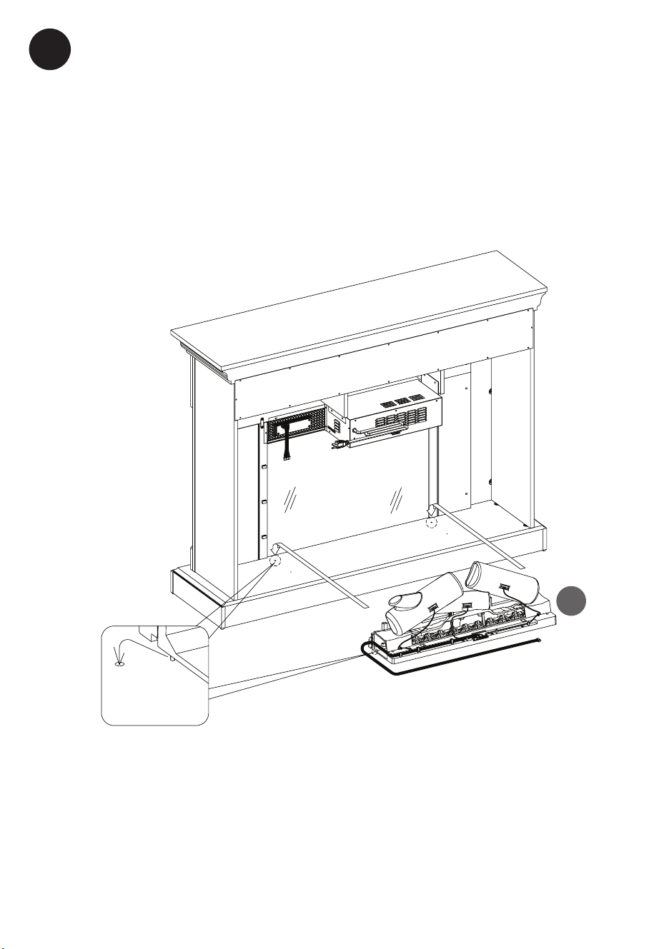
29
Assembling the Fireplace
• Place the assembled log set into the back of the unit behind the glass
panel.
• Push the tabs beneath the log set into the holes on the bottom panel.
Ensamblaje de la chimenea
• Coloque el juego de leños ensamblado en la parte posterior de la unidad
detrás del panel de vidrio.
• Inserte las lengüetas debajo del juego de leños en los oricios del panel
inferior.
38
28WM7145 REV1.0
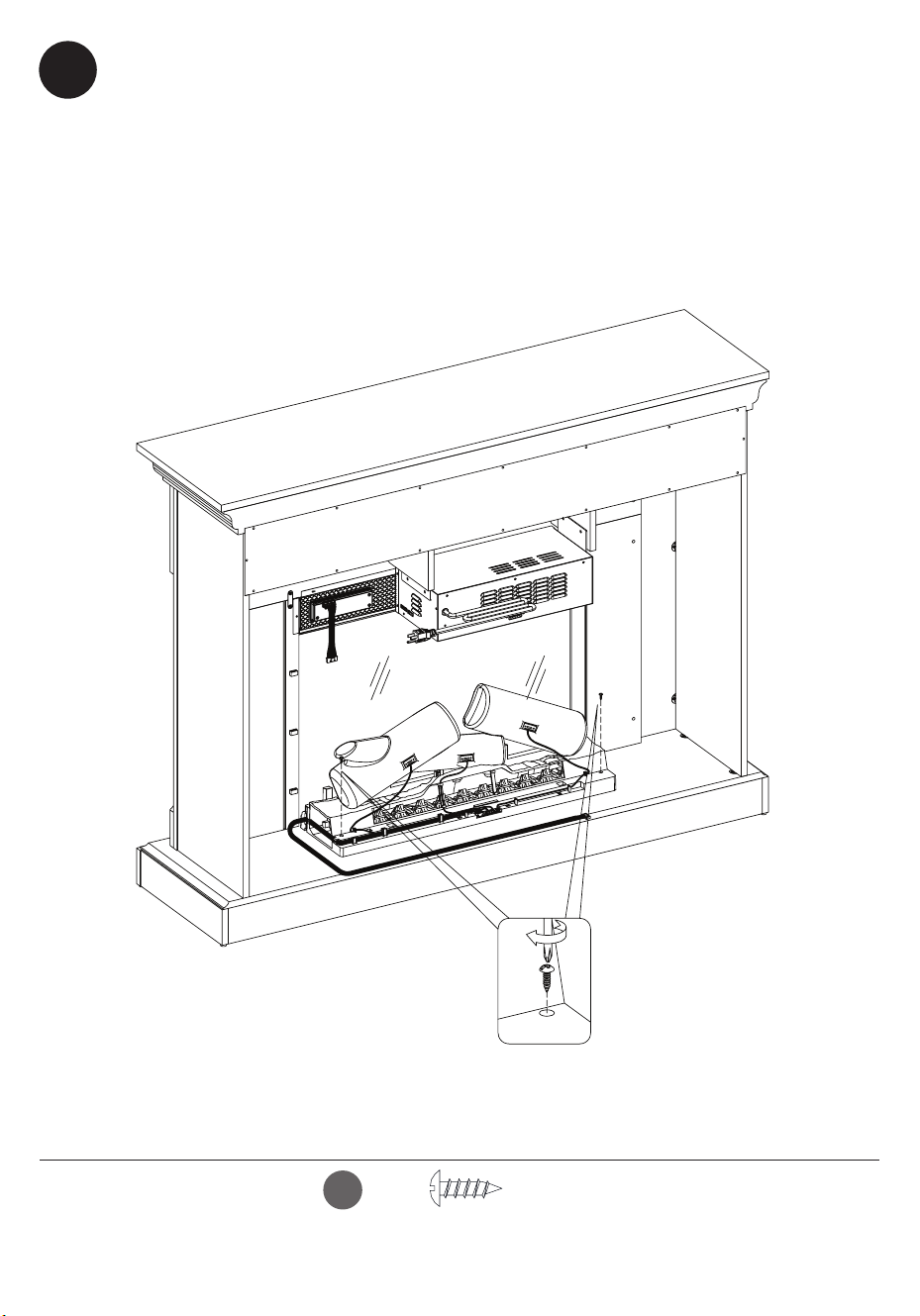
30
Securing the Log Set
• Once the log set is in place, secure with Screws (GG) through the bottom
of the log set and into the base.
Fijación del juego de leños
• Una vez que el juego de leños esté en su lugar, fíjelo con tornillos (HH) en la
base a través de la parte inferior del juego de leños.
GG
[x2]
39
28WM7145 REV1.0
Control panel cable
Cable del panel de control
Ember Bed Connection Wire
Cable de conexión del lecho
de brasas
31
Connecting the Fireplace Wiring
• Connect Control Panel Cable to heater.
• Insert the Ember Bed Connection Wire into the heater.
Conexión del cableado de la chimenea
• Conecte el cable del panel de control al calentador.
• Inserte el cable de conexión del lecho de brasas en el calentador.
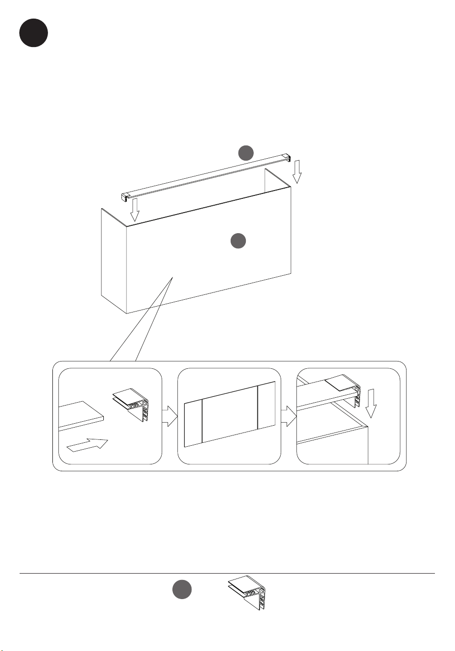
40
28WM7145 REV1.0
32
Placing the Fireplace Background
• Position the Back Panel Frame (Z) above the Electric Fireplace Back Panel
(I), sliding into place as shown.
Colocación del Fondo de la Chimenea
• Coloque el Marco del Panel Trasero (Z) sobre el Panel Trasero de la
Chimenea Eléctrica (I), deslizándolo en su lugar, tal como se muestra.
Z
I
II
[x2]
41
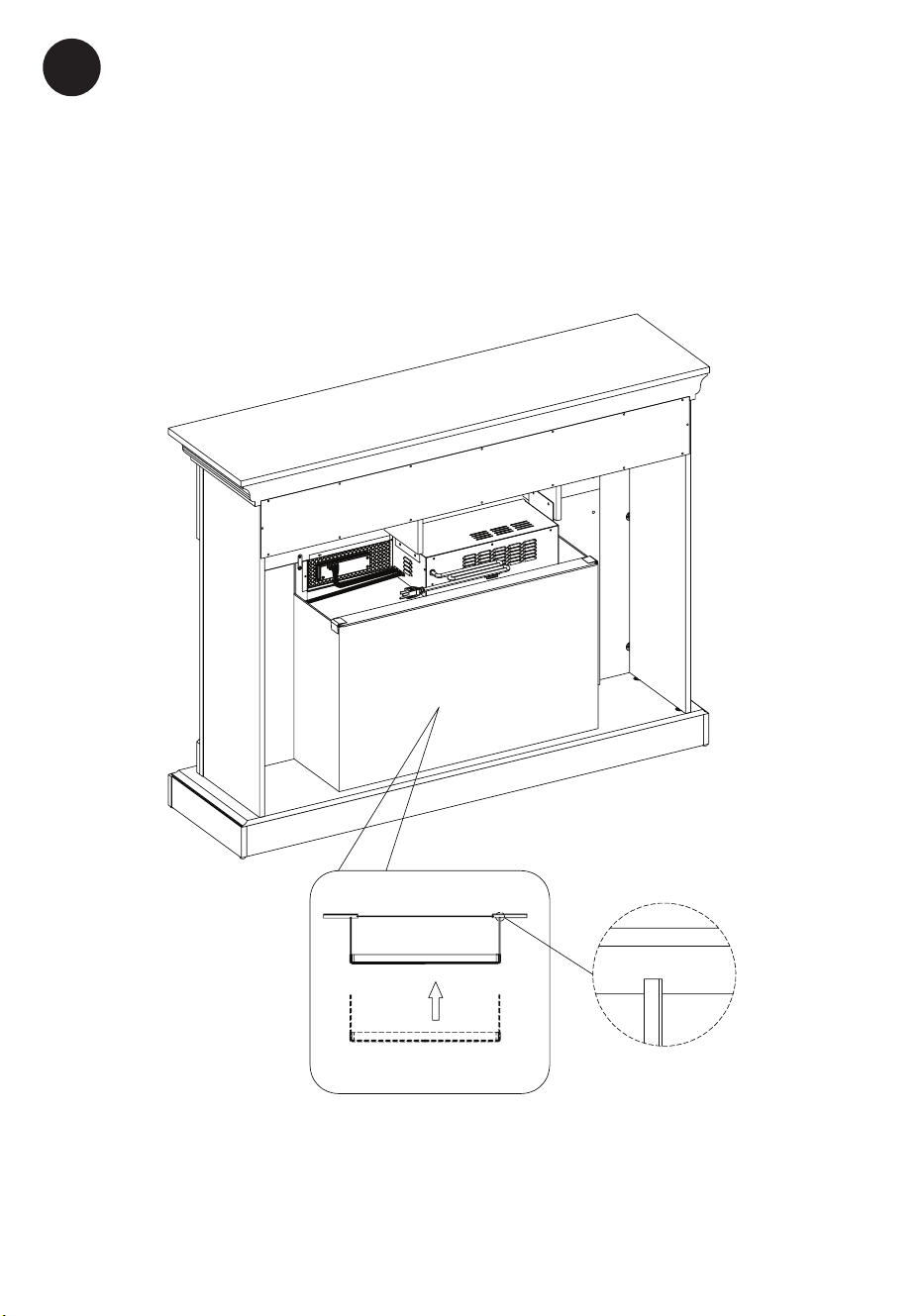
28WM7145 REV1.0
33
Positioning the Fireplace Background
• Slide the Back Panel into the grooves on the back of the replace surround
panel assembly as shown.
Posicionamiento del Fondo de la Chimenea
• Deslice el Panel Trasero en las ranuras de la parte trasera del conjunto del
panel envolvente de la chimenea, tal como se muestra.
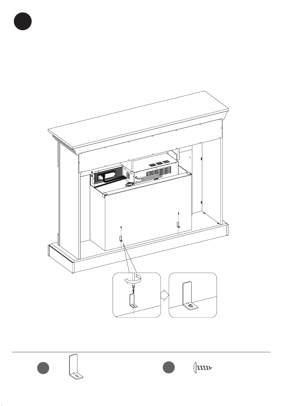
42
28WM7145 REV1.0
34
Securing the Fireplace Background
• Fasten each Back Panel Bracket (JJ) with Screws (KK), using a Phillips
screwdriver as shown.
Fijación del fondo de la chimenea
• Fije cada Soporte del Panel Trasero (JJ) con Tornillos (KK), utilizando un
destornillador Phillips, tal como se muestra.
JJ
KK
[x2]
[x2]
43
28WM7145 REV1.0
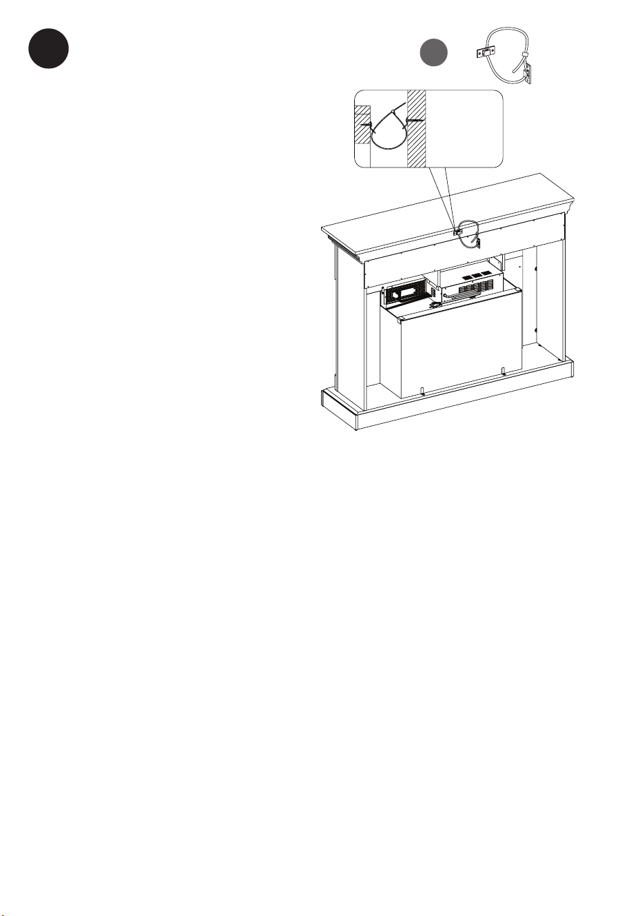
Installing the Tip Restraint Hardware
• When the Tipping Restraint
Hardware (LL) is properly installed,
it can provide protection against
unexpected tipping of the Unit
due to small tremors, bumps or
climbing.
• Each Tipping Restraint Hardware
(LL) includes one Unit Anchor, one
Wall Anchor, one Anchor Tether,
and four Anchor Screws. Use these
to complete the following steps for
a proper installation.
• Locate a secure wall stud behind
the unit closest to left side.
• Align the Unit Anchor with a
wall stud and attach to the Unit
with two Anchor Screws using a
Philips screwdriver. The Anchor
Screws must pass through the Top
Assembly for proper installation.
• Align the Wall Anchor in the center of the wall stud, at level with the Unit
Anchor, and with two Anchor Screws using a Philips screwdriver.
• On the Anchor Tether, detach the cable from the connector and
loop the loose cable through the eyelets on the Wall Anchor and Unit
Anchor. Reattach the loose cable to the connector, but do not tighten.
• Locate a secure wall stud behind the Unit closest to the right side and
repeat the steps above.
• Tighten both Anchor Tethers by pulling the cable the through
connector.
NOTE: Installation of the Tipping Restraint Hardware (LL) will provide a
small space between the wall and the Unit. This will allow you to run
power cords and connector cables to your television or other devices
placed on top of the Unit.
35
Wall Stud
Poteau Mural
Montante De
Madera
LL
[x1]

44
28WM7145 REV1.0
Warning: You must install the tip restraint hardware to help prevent any
accidents or damage to the unit. We strongly recommend attaching the tip
restraint hardware to a wall stud and your unit. For all other wall types, please
visit your local hardware store to obtain the proper hardware.
Advertencia: Debe instalar el Herraje contra Caídas para evitar accidentes
o que se dañe la unidad. «Recomendamos enfáticamente sujetar el extremo
de la herramienta de retención a un perno de pared y su unidad». Respecto
de todos los demás tipos de pared, vaya a su ferretería local para obtener las
herramientas adecuadas.
• Localice un montante de pared seguro detrás de la unidad más cercana al
lado izquierdo.
• Alinee el Anclaje de la Unidad con el montante de la pared y fíjelo a la
Unidad con dos Tornillos de Anclaje utilizando un Destornillador Philips. Los
Tornillos de Anclaje deben pasar a través del Conjunto Superior para una
correcta instalación.
• Alinee el Anclaje de Pared en el centro del montante de la pared, a nivel
con el Anclaje de la Unidad, y con dos Tornillos de Anclaje utilizando un
Destornillador Philips.
• En el Anclaje, separe el cable del conector y pase el cable suelto por los
ojales del Anclaje de Pared y del Anclaje de la Unidad. Vuelva a colocar el
cable suelto en el conector, pero no lo apriete.
• Localice un perno de pared seguro detrás de la unidad más cercana al
lado derecho y repita los pasos anteriores.
• Apriete ambos Anclajes tirando del cable a través del conector.
NOTA: La instalación de los Herrajes de Restricción de Vuelco (LL)
proporcionará un pequeño espacio entre la pared y la unidad. Esto le
permitirá pasar los cables de alimentación y los cables de conexión a su
televisión u otros dispositivos colocados encima de la unidad.
Instalación de los herrajes de contención de vuelco
• Cuando los Herrajes de Restricción de Vuelco (LL) están correctamente
instalados, pueden proporcionar protección contra el vuelco inesperado de
la Unidad debido a pequeños temblores, golpes o escalada.
• Cada Herraje de Restricción de Vuelco (LL) incluye un Anclaje de la
Unidad, un Anclaje de Pared, una Correa de Anclaje y cuatro Tornillos de
Anclaje. Utilícelos para completar los siguientes pasos para una instalación
adecuada.

45
28WM7145 REV1.0
CARE /
MAINTENANCE
CUIDADO /
MANTENIMIENTO
Care and Maintenance
• Use a soft, clean cloth that will not scratch the
surface when dusting.
• Use of furniture polish is not necessary. Should you
choose to use polish, test rst in an inconspicuous
area.
• Using solvents of any kind on your furniture may
damage the nish.
• Never use water to clean your furniture as it may
cause damage to the nish.
• Always use coasters under beverage glasses and
owerpots.
• Liquid spills should be removed immediately, as it
may damage the furniture. Use a soft, clean cloth
and blot the spill gently. Avoid rubbing.
• Always use protective pads under hot dishes and
plates. Heat can cause chemical changes that may
create spotting within the furniture.
We hope you enjoy your purchase for many years.
Thank you for your purchase!
Esperamos que disfrute de su compra durante
muchos años. ¡Gracias por su compra!
Cuidado / Mantenimiento
• Use un paño suave y limpio que no raye la supercie
cuando elimine el polvo.
• El uso de cera para muebles no es necesario. Si elige
utilizar la cera, realice primero una prueba en un área
discreta.
• Usar solventes de cualquier clase en sus muebles
puede dañar el acabado.
• Nunca utilice agua para limpiar sus muebles, ya que
puede causar daños en el acabado.
• Siempre utilice posavasos para colocar los vasos de
bebidas y las macetas.
• Los derrames de líquidos se deben de secar
inmediatamente, ya que pueden dañar el mueble.
Use un paño suave y limpio y seque el derrame con
cuidado. Evite frotar.
• Siempre utilice almohadillas protectoras debajo de
los platos y vajillas calientes. El calor puede causar
cambios químicos los cuales pueden crear manchas
en los muebles.
46
28WM7145 REV1.0
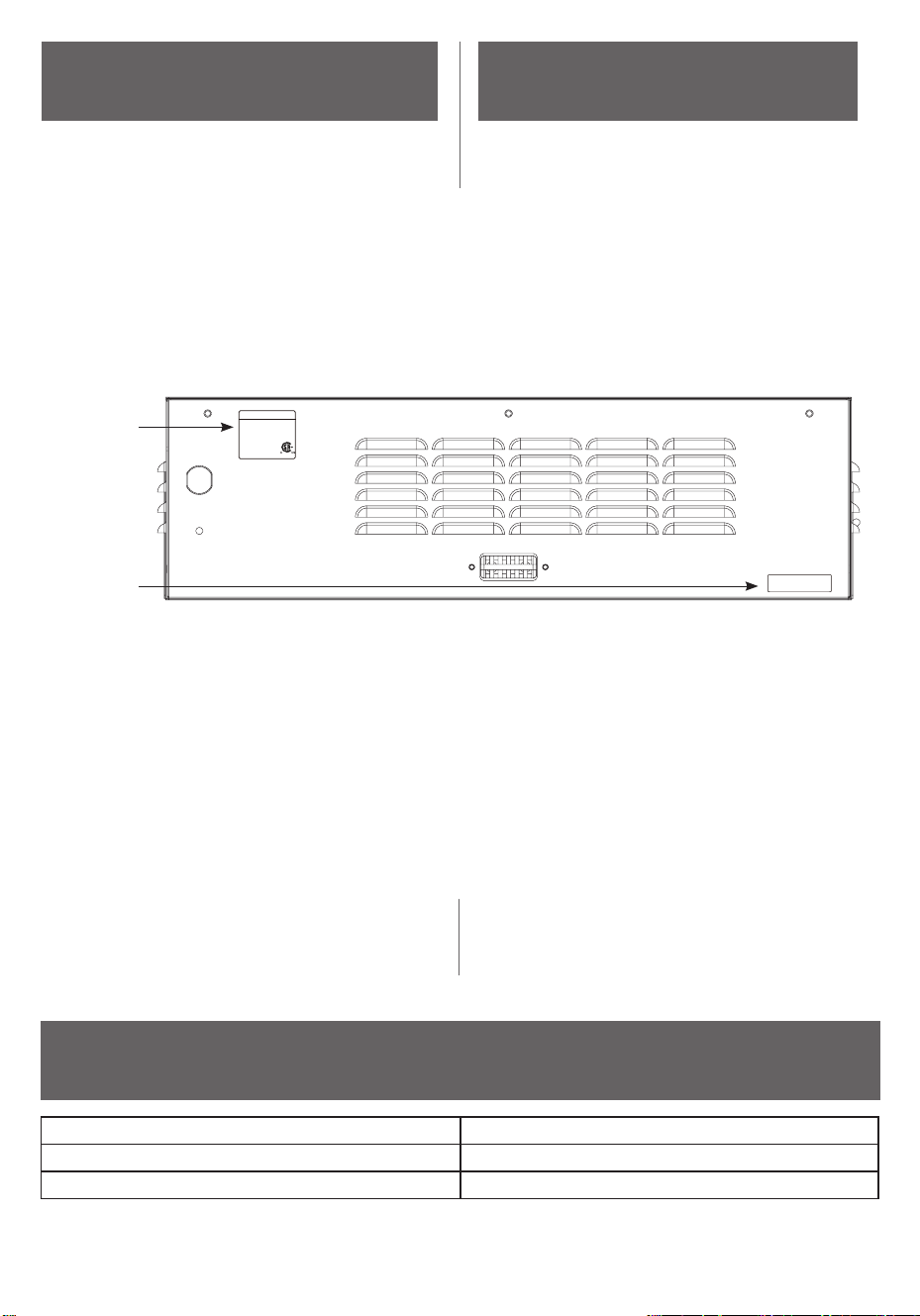
PRODUCT SPECIFICATIONS
ESPECIFICACIONES ELÉCTRICAS
GETTING STARTED
PARA EMPEZAR
2. Go to tsicustomerservice.com
for product warranty registration. If you are unable to
complete registration save your proof of purchase for
warranty purposes.
2. Visitar tsicustomerservice.com para el registro
de la garantía del producto. Si usted no puede
completar el registro guarde el comprobante de
compra para hacer válida la garantía.
1. The serial number is located on the back of the
heater. The serial number is necessary for product
warranty registration and customer service.
1. El número de serie se encuentra en la parte
posterior de la calentador, el número de serie
es necesario para el registro de la garantía del
producto y el servicio de atención al cliente.
Model Number
Número de modelo
Serial Number
Número de Serie
1-866-661-1218
tsicustomerservice.com
SN #: AJ-XXXXX-X
Date Code/ Code de Date/ Código Fecha :
ELECTRIC FIREPLACE/FOYER
ÉLECTRIQUE/INSERTO PARA CHIMENEA
MODEL / MODÈLE / MODELO
Twin-Star International, Inc.
www.twinstarhome.com
Made in Vietnam
Fabriqué au Vietnam
Hecho en Vietnam
28DI039FGL
VOLTS WATTS/VATIOS HZ
120V~ 1500 60
220391
VOLTAGE / TENSIÓN 120VAC, 60 Hz
AMPS / AMPERIOS 12.5 Amps / 12.5A
WATTS / POTENCIA 1500 Watts / 1500 W

47
28WM7145 REV1.0
IMPORTANT
INSTRUCTIONS
INSTRUCCIONES
IMPORTANTE
Cuando utilice electrodomésticos,
siempre tome medidas de precaución
básicas para evitar incendios,
descargas eléctricas y lesiones
personales. Entre ellas:
When using electrical appliances,
basic precautions should always
be followed to reduce the risk of re,
electrical shock, and injury to persons
including the following:
1. Read all instructions before using
this appliance.
DANGER – High temperatures
may be generated under certain
abnormal conditions. Do not
partially or fully cover or obstruct the
front of this heater.
3. CAUTION: Never leave the heater
operating unattended. Extreme
caution is necessary if unsupervised
children or persons with a disability
are nearby.
4. The appliance is not to be used by
children or persons with reduced
physical, sensory or mental
capabilities, or lack of experience and
knowledge, unless they have been
given supervision or instruction.
5. Always unplug this appliance when
not in use.
6. Do not
operate any heater with a
damaged cord or plug or after
the heater malfunctions, has been
dropped or damaged in any
manner. Discard heater, or return
to authorized service facility for
examination and/or repair.
7. Do not use outdoors.
8. This heater is not intended for use
in bathrooms, laundry areas and
similar indoor locations. Never
locate this appliance where it may
fall into a bathtub or other water
container.
9. Do not run cord under carpeting.
Do not cover cord with throw rugs,
runners or the like. Arrange cord
away from trafc areas and where
it will not be tripped over.
2.
1. Lea todas las instrucciones antes de
usar este electrodoméstico.
PELIGRO – Es possible que altas
temperaturas se pueden generar
bajo ciertas condiciones anormales.
No cubra parcialmente o totalmente
ni obstruya la parte delantera de este
calentador.
3. PRECAUCIÓN: Nunca deje el
calentador operando de forma
desatendida. Extremo cuidado es
necesario si hay niños o personas
discapacitadas sin supervisión cerca.
4 .
Este electrodoméstico no debe ser
usado por personas o niños con
capacidades físicas, sensoriales o
mentales reducidas o sin experiencia
ni conocimientos, a menos que una
persona responsable de su seguridad
les brinde supervisión o capacitación
respecto al uso del electrodoméstico.
5. Siempre desenchufe este
electrodoméstico cuando no lo use.
6. No opere ningún calentador después
de que el cable de alimentación o
el enchufe estén dañados, o que el
calentador esté defectuoso, caído o
dañado de alguna manera. Deseche
el calentador o devuélvalo a un
centro de servicio autorizado para su
inspección y / o reparación.
7. No lo use en exteriores.
8. Este calentador no se debe usar
en el baño, lavadero y en espacios
húmedos similares interiores. Nunca
coloque este calentador donde se
pueda caer dentro de una bañera u
otro contenedor de agua.
2.
48
28WM7145 REV1.0
10. To disconnect heater, turn
controls to off, and turn off
power to heater circuit at main
disconnect panel (or operate
internal disconnect switch if
provided).
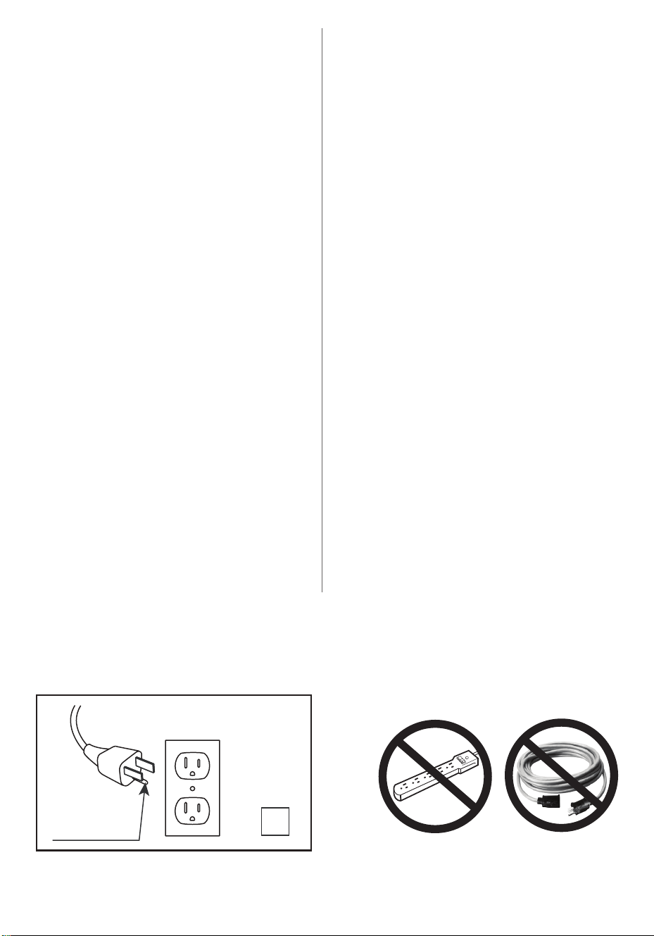
11. Connect to properly grounded
outlets only. This heater is for use
on 120 volts. The cord has a plug
as shown at A in Fig.1. Do not
use a 2 prong adapter. Never
use with an extension cord or
relocatable power tap (outlet/
power strip).
Do not insert or allow foreign
objects to enter any ventilation
or exhaust opening as this may
cause an electric shock, re, or
damage the appliance.
13. To prevent a possible re, do
not block air intakes or exhaust
in any manner. Do not use on
soft surfaces, like a bed, where
opening may become blocked.
14. This appliance has hot, arcing or
sparking parts inside. Do not use
it in areas where gasoline, paint
or ammable liquids are used
or stored. This replace should
not be used as a drying rack for
clothing. Christmas stockings or
decorations should not be hung
in the area of it.
No coloque el cable debajo de
una alfombra. No cubra el cable
con alfombras, tapetes o similares.
Coloque el cable lejos de zonas de
tránsito en donde nadie se pueda
tropezar y caer.
Para desconectar el calentador,
apague los controles y apague la
fuente de alimentación del circuito
del calentador en el disyuntor
principal (para operar el interruptor
de desconexión interno si se
proporciona). Conectar solamente a
una toma de corriente con conexión
a tierra adecuada. Este calentador
debe utilizarse con 120 voltios. El
cable incluye un enchufe tal como
se muestra en la gura A en la Fig.1.
No utilice un adaptador de 2 clavijas.
Nunca use un cable de extensión o
tomas de alimentación reubicable
(enchufes/ regletas).
No introduzca objetos extraños ni
permita que entren en las aberturas
de ventilación o escape, ya que
pueden provocar descargas
eléctricas, incendios o daños en el
electrodoméstico.
Para evitar incendios, no bloquee
las entradas ni salidas de aire de
ninguna manera. No use sobre
supercies blandas, como una cama,
donde las aberturas se puedan
bloquear. electrodoméstico.
12.
A
Fig.1
9.
10.
11.
12.
13.
SAVE THESE INSTRUCTIONS
GUARDE ESTAS INSTRUCCIONES

49
28WM7145 REV1.0
15. Use this appliance only as described
in the manual. Any other use not
recommended by the manufacturer
may cause re, electric shock, or
injury to persons.
16. This heater may include a visual
alarm to warn that parts of the
heater are getting excessively hot. If
the alarm ashes immediately turn
the heater off and inspect for any
objects on or adjacent to the heater
that may cause high temperatures.
DO NOT OPERATE THE HEATER WITH
THE ALARM FLASHING!
14. Este electrodoméstico tiene en su
interior piezas calientes y piezas que
forman arcos eléctricos o que echan
chispas. No lo use en áreas donde se
use o almacene gasolina, pintura o
líquidos inamables. Esta chimenea
no se debe usar como una rejilla
para secar ropa. No cuelgue medias
navideñas u otras decoraciones
sobre o cerca de este producto.
15. Utilice este electrodoméstico sólo
como se describe en este manual.
Cualquier otro uso no recomendado
por el fabricante puede causar
incendios, descargas eléctricas o
lesiones personales.
16. El radiador puede incluir una
alarma visual para advertir que
las partes del radiador se están
sobrecalentando. Si la alarma
comienza a brillar, desconecte
inmediatamente el radiador y revise
los objetos sobre éste o adyacentes
al radiador que puedan causar el
sobrecalentamiento. ¡NO OPERE EL
RADIADOR CON LA ALARMA CUANDO
ESTÉ BRILLANDO!
SAVE THESE INSTRUCTIONS
GUARDE ESTAS INSTRUCCIONES
50
28WM7145 REV1.0
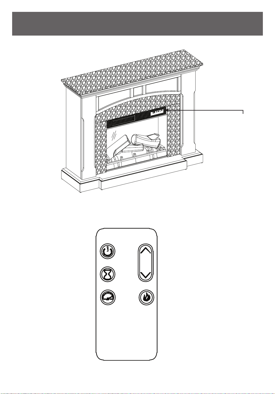
OPERATION INSTRUCTIONS
INSTRUCCIONES DE OPERACIÓN
The heater can be operated by either the remote control or the control panel.
El calentador puede ser operado por el control remoto o el panel de control.
Control Panel
Panel de control
51
28WM7145 REV1.0
Press the heater button on the
control panel to turn on/off(00) and
adjust the heater setting.
To change between °F and °C, press
and hold the HEATER button on the
control panel for 3 seconds.
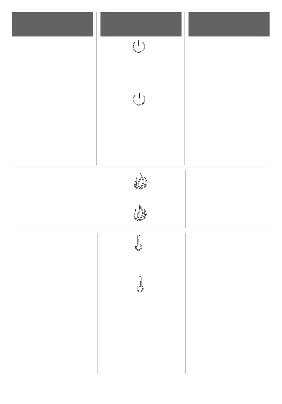
The thermostat setting range
is 62°F - 82°F( 17°C - 27°C) or
continuously ON.
Presionando el botón el panel
de control del calentador para
encender / apagar el ajuste del
calentador y ajustar el calentador.
Para cambiar entre °F y °C
mantenga pulsado el botón del
CALENTADOR en el panel de control
durante 3 segundos.
El rango de ajuste del termostato
es de 62°F - 82°F o 17°C - 27°C o
continuamente encendido.
CALENTADOR
HEATER
FUNCTION
FUNCIÓN
ICON
ICONO
DESCRIPTION
DESCRIPCIÓN
FLAME
LLAMA
There are 5 brightness levels that
can be selected and 00 (OFF)
setting. Settings F5 - F1 decrease in
brightness.
Hay 5 niveles de brillo que se pueden
seleccionar y ajuste 00 (APAGADO).
Ajustes de F5 - F1 para disminuir el
brillo.
POWER
ENERGÍA
The POWER button supplies power
to all the functions of the heater.
Pressing the POWER button again
will put the heater in standby
mode.
Holding the Power button on the
control panel for 10 seconds will
disable the heater function.
El botón de encendido
suministra energía a todas
las funciones del calentador.
El botón de encendido se
coloque la unidad en modo
de espera.
Con el aparato encendido
mantenga presionado el botón
de encendido en el panel de
control durante 10 segundos para
desactivar o volver a activar la
función de calentador.
52
28WM7145 REV1.0
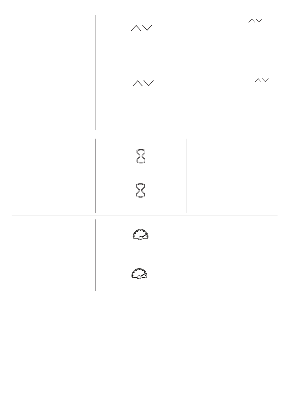
The up and down buttons “ ” on
the remote will increase / decrease
temperature setting.
The thermostat setting range
is 62°F - 82°F( 17°C - 27°C) or
continuously ON.
The thermostat is adjustable by 2°F or
1°C increments.
TEMPERATURE INCREASE /
DECREASE
TEMPERATURA AUMENTARÁN /
DECRASE
El botones de arriba y abajo “ ”
en el control remoto aumentarán /
decrase ajuste de temperatura.
El rango de ajuste del termostato
es de 62°F - 82°F o 17°C - 27°C o
continuamente encendido.
El termostato es ajustable en
incrementos por 2°F o 1°C.
TIMER
Pressing the timer button will
cycle through the timer settings:
30 minutes, 1 Hour, 2H, 3H, 4H, 5H,
6H, 7H, 8H, 9H and 00 (OFF).
TEMPORIZADOR
Al presionar el botón del temporizador,
hará un ciclo a través de la
conguración del temporizador; 30
minutos, 1 hora, 2H, 3H, 4H, 5H, 6H, 7H,
8H, 9H y 00 (apagado).
FLAME SPEED
VELOCIDAD DE LLAMA
The ame speed is only adjustable
from the remote control. Each
ame setting has 5 speed options
available. Setting S1 is slowest
ranging up to setting S5 which is
the fastest.La velocidad de la llama
es sólo ajustable desde el control
remoto. Cada opción de color de la
llama Spectrare tiene opciones de
velocidad disponibles.El ajuste S1 es
el más lento que varía hasta el ajuste
de S5, que es la más rápido.
53
28WM7145 REV1.0
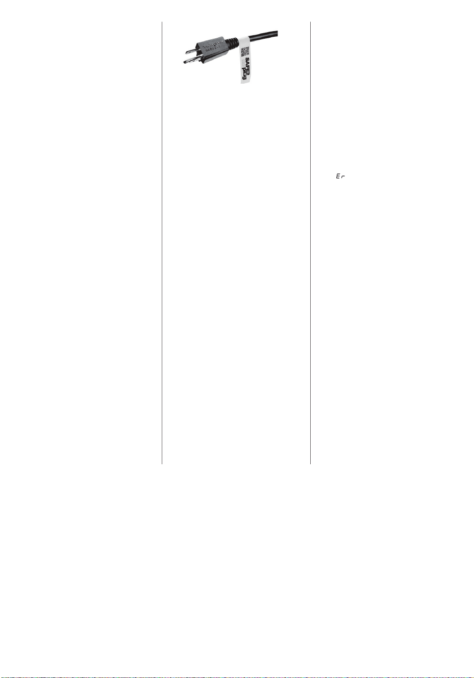
SAFER PLUG
®
This product is equipped with a Safer
Plug
®
; an advanced safety device
that helps detect electrical res
caused from faulty outlets.
Overloading of outlets, adapters
and surge protectors may cause
overheating, damage, and increase
risk of res. Safer Plug
®
continuously
monitors the temperature in the
plug and outlet and will turn off
the heater to prevent unsafe outlet
overheating.
If the Safer Plug
®
cuts the power
due to unsafe conditions it will show
an “ ”message on the screen.
If this occurs the Safer Plug
®
has
prevented a potentially unsafe
condition.
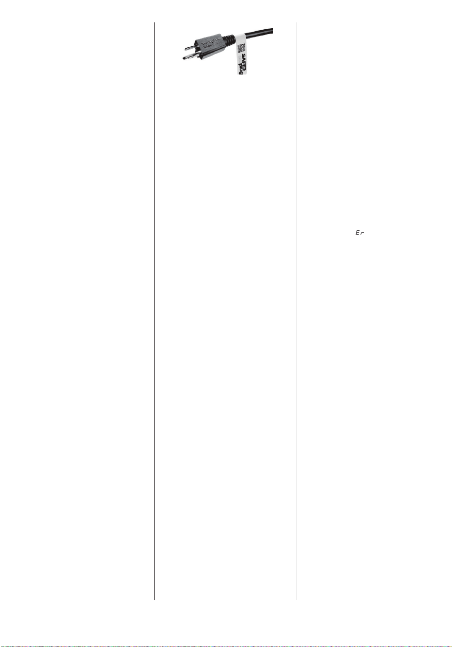
To reset the device if this occurs, rst
allow the plug to cool down. Once
the plug has cooled down, unplug
the device and wait 5 seconds, then
plug back in and continue to use
normally.
If the Safer Plug
®
continues to
activate your outlet may be faulty.
Check your heater cord and
plug connections. Faulty wall
outlet connections or loose plugs
can cause the outlet or plug to
overheat. Be sure the plug ts tight
in the outlet. Heaters draw more
current than small appliances, so
overheating of the outlet may occur
even if it has not occurred with the
use of other appliances. During use,
check frequently to determine if your
plug, outlet or faceplate is HOT! If so,
discontinue use of the heater and
have a qualied electrician check
and/or replace the faulty outlet(s).
54
28WM7145 REV1.0
Este producto está equipado con
un Safer Plug
®
; un dispositivo de
seguridad avanzada que ayuda
a detectar los incendios eléctricos
causado de los tomacorrientes
defectuosos.
La sobrecarga del tomacorriente,
adaptadores y protectores de
sobretensión puede causar
sobrecalentamiento, daños, y
aumentar el riesgo de incendios.
El Safer Plug
®
monitoriza
continuamente la temperatura
en el enchufe y el tomacorriente
y se apagará el calentador para
evitar el sobrecalentamiento del
tomacorriente inseguro.
Si Safer Plug
®
interrumpe la
alimentación debido a las
condiciones inseguras se mostrará
una mensaje “ ” en la pantalla.
Si esto ocurre, el Safer Plug
®
ha impedido una condición
potencialmente insegura.
Para reiniciar el dispositivo si esto
ocurre, deje que el enchufe se
enfríe. Una vez que el enchufe
se haya enfriado, desconecte el
dispositivo y espere 5 segundos,
luego conecte de nuevo y continuar
utilizando normalmente.
Si el Safer Plug
®
continúa para
activar el tomacorriente puede
estar defectuoso. Compruebe
que su cable de calefactor
y las conexiones de enchufe.
Los tomacorrientes de pared
defectuosos o los enchufes
ojos pueden hacer que el
tomacorriente o enchufe a
sobrecalentarse. Asegúrese de
que el el enchufe ajusta apretado
en el tomacorriente. Calentadores
consumen más corriente que los
pequeños electrodomésticos, el
recalentamiento del tomacorriente
puede ocurrir incluso si no
ha ocurrido con el uso de
otros aparatos. ¡Durante el uso
compruebe con frecuencia para
determinar si el tomacorriente
de enchufe y placa frontal está
CALIENTE ! Si es así, deje de
utilizar el calentador y tienen un
cheque electricista calicado y /
o reemplazar el tomacorriente (s)
defectuoso.
SAFER PLUG
®
55
28WM7145 REV1.0
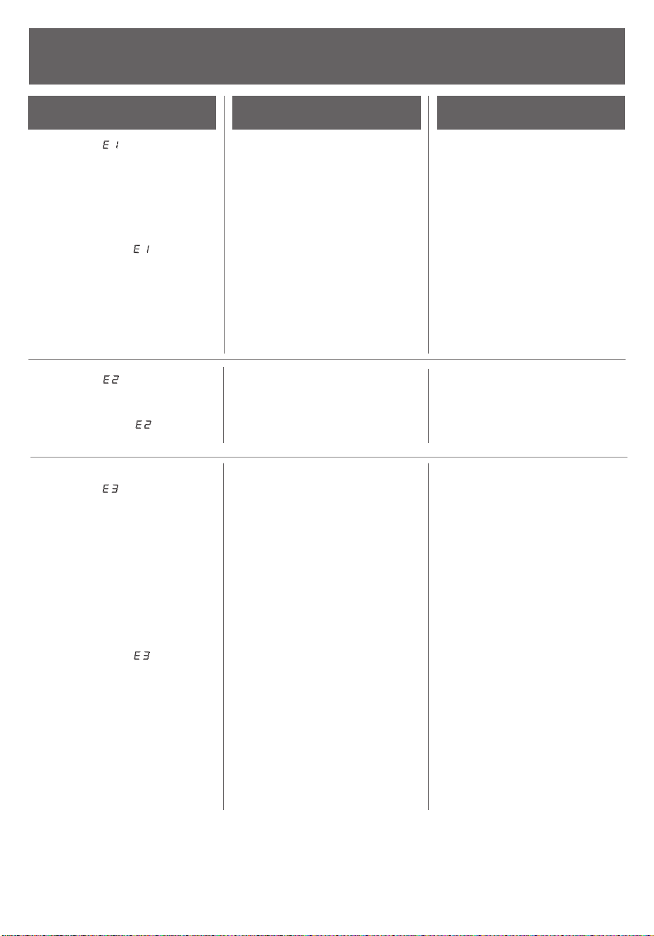
TROUBLESHOOTING
SOLUCIÓN DE PROBLEMAS
Display shows “ ”
Display shows “ ”
Display shows “ ”
La pantalla muestra “ ”
La pantalla muestra “ ”
El sensor del termostato está en
cortocircuito.
El restablecimiento manual
de protección contra el
sobrecalentamiento se ha activado.
La pantalla muestra “ ”
The thermostat sensor
is broken or disconnected.
The thermostat sensor
is short circuited.
Manual Reset overheat protection
has triggered.
El sensor del termostato
está dañado o desconectado.
Unplug the replace, remove the
back panel of the heater box and
check that the thermostat is plugged
into the main circuit board. If this
does not solve the problem, contact
customer service for a replacement
thermostat sensor.
Desenchufe la chimenea, quite el
panel posterior de la chimenea
y revise que el termostato esté
conectado a la placa del circuito
principal. Si esto no resuelve el
problema, comuníquese con
atención al cliente para obtener un
remplazo del sensor del termostato.
Contact customer service for a
replacement thermostat sensor.
Comuníquese con atención al
cliente para el remplazo del sensor
del termostato.
Inspect the heater and check
that the air inlets and outlets are
not blocked as this may cause
overheating. Unplug the heater for
30 minutes and allow it to cool down.
Re-plug and operate, but monitor the
heater for signs of overheating. If the
problem persists, discontinue use of
the heater and contact customer
service.
Inspeccione el calentador y verique
que las entradas y salidas de
aire no estén bloqueadas, pues
pueden causar sobrecalentamiento.
Desenchufe el calentador durante
30 minutos y deje enfriar. Vuelva a
enchufar y a operar, y supervise el
calentador para detectar signos
de sobrecalentamiento, y si el
problema persiste, interrumpa el uso
del calentador y comuníquese con
atención al cliente.
PROBLEM
PROBLEMA
ROOT CAUSE
ORIGEN DE LA CAUSA
CORRECTIVE ACTION
MEDIDAS CORRECTIVAS

56
28WM7145 REV1.0
Heater does not
blow warm air.
El calentador no sopla
aire caliente.
Cool down cycle.
Ciclo de enfriamiento.
Normal operation. Heater will
continue to run for less than one
minute before shutting down. Times
will vary based on temperatures.
During this time cool air will blow.
Esto es una operación normal, el
Esto es una operación normal, el
ventilador continuará funcionando
durante menos de un minuto para
enfriar los componentes internos.
Períodos pueden variar dependiendo
de la temperatura. Durante este
tiempo, el aire frío se fundirá.
Display shows “ ”
La pantalla muestra “ ”
Power cord overheating
protection has activated.
Check your heater cord and plug
connections. Faulty wall outlet
connections or loose plugs can
cause the outlet or plug to overheat.
Be sure the plug ts tight in the outlet.
Heaters draw more current than
small appliances, so overheating
of the outlet may occur even if it
has not occurred with the use of
other appliances. During use check
frequently to determine if your plug,
outlet or faceplate is HOT! If so,
discontinue use of the heater and
have a qualied electrician check
and/or replace the faulty outlet(s).
Compruebe que el cable del
calentador y las conexiones del
enchufe. Conexiones de tomas de
corriente defectuosas o enchufes
sueltos pueden hacer que la
toma de corriente o el enchufe
se recaliente. Asegúrese de que
el enchufe queda ajustado a la
toma de corriente. Los calentadores
consumen más corriente que los
pequeños electrodomésticos, el
recalentamiento de la toma de
corriente puede ocurrir inclusosi
no se ha producido con el uso
de otros aparatos. Durante el uso,
compruebe con frecuencia para
determinar si su enchufe o la placa
frontal está CALIENTE! Si es así, deje
de utilizar el calentador y contacte
con un electricista cualicado para
que compruebe o reemplace los
enchufe(s) defectuosos.
Poder sobrecalentamiento cable
protección se ha activado.

57
28WM7145 REV1.0
No power, logs do not glow.
Sin corriente, los registros
no brillan.
No power to the unit
No hay corriente
en la unidad.
Check that unit is plugged into a
standard 120V outlet. Press power
button several times, make sure power
is set at “ON” position.
Compruebe que la unidad esté
enchufada a una toma de corriente
estándar de 120V. Presione el botón
de encendido varias veces, y
asegúrese de que la energía este
jada en la posición de “ENCENDIDO”.
Logs glow, but no ame effect.
Los registros brillan, pero
no tienen efecto de llama.
Flame effect turned off
El efecto de llama
está apagado.
Press ame button several times.
Pulse el botón de llama
varias veces.
Heater does not blow warm air.
El calentador no sopla
aire caliente.
Thermostat setting is preventing
heater from turning on.
El ajuste del termostato
está evitando que el
calentador se encienda.
Adjust the temperature settings
to ensure that the thermostat is
set higher than the current room
temperature.
Ajuste la conguración de la
temperatura para asegurar que el
termostato está jado por encima
de la temperatura actual de la
habitación.
Flame effect works, but heater
function does not and the ember
bed ashes when the heater button
is pressed.
El efecto de llama funciona, pero la
función del calentador no funciona
y el peldaño parpadea cuando
el botón del calentador está
presionado.
The heater is disabled.
El calentador está desactivado.
With the power on, press and hold
the POWER button on the control
panel for 10 seconds. Once re-
enabled the ember bed lights will
ash multiple times.
Con la corriente encendida, presione
y mantenga pulsado el botón de
encendido en el panel de control
durante 10 segundos. Una vez que
lo vuelve a habilitar, las luces del
peldaño destellarán varias veces.
Remote control is not working.
El control remoto no funciona.
No batteries
No hay pilas
Change the remote batteries.
Cambie las pilas del control remoto.

58
28WM7145 REV1.0
Opere el transmisor remoto a una
velocidad más lenta. Pulse los
botones del control remoto con
una moción uniforme y presión
suave. Pulsar los botones en una
sucesión rápida y de forma repetida
puede causar que el transmisor mal
funcione.
Operate the remote at a distance
less than 20 feet from the front of the
appliance; point the remote
at the control panel.
Operar el control remoto a una
distancia inferior a 20 pies desde la
parte delantera del aparato; apunte
el control remoto al panel de control.
Mala Señal.
Distance
Distancia.
El control remoto no funciona.
El control remoto no funciona.
Remote control is not working.
Remote control is not working. Poor signal Operate remote transmitter at a slow
measured pace. Press the remote
control buttons with an even motion
and gentle pressure. Repeatedly
pressing buttons in rapid succession
may cause the transmitter to
malfunction.

59
28WM7145 REV1.0
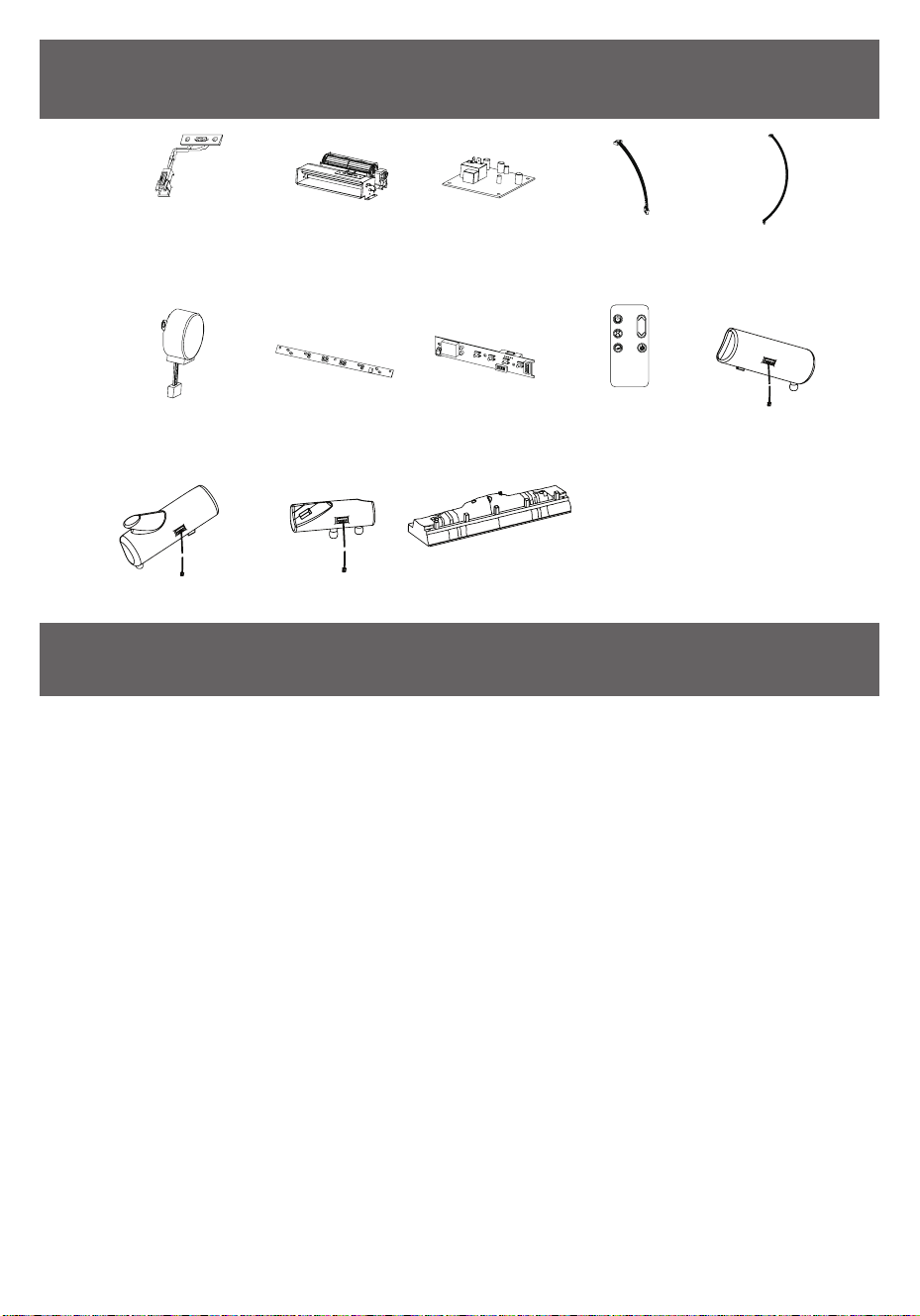
REPLACEMENT PARTS
PIÈCES DE REMPLACEMENT
PART
PIEZA
PART NAME
NOMBRE DE LA PIEZA
PART NUMBER
NÚMERO DE PIEZA
1
Thermostat Sensor
Sensor de Termostato
Y21-S307-P186SS
2
Blower/ Heater Assembly
Asamblea de Soplador / Calentador
Y21-S307-P01SS
3
Main Circuit Board
Placa De Circuito Principal
Y21-S307-P15SS
4
Control Panel Cable
Cable de conexión del botón
Y21-S327-P187SS
5
Ember Bed Connection Wire
Cable de conexión del lecho de brasas
Y21-S307-P188SS
6
Flame Generator Drive Motor
Llama Generador De Accionamiento Del Motor
Y21-S307-P189SS
7
Flame Circuit Board
Tarjeta de circuitos de llama
Y21-S307-P40SS
8
Control Panel Circuit Board
Tarjeta de circuitos del panel de control
Y21-S307-P32SS
9
Remote Control
Control Remoto
P185
10
Log Set Left
Juego de leños izquierdo
Y21-S307-P20LSS
11
Log Set Right
Juego de leños derecho
Y21-S307-P20RSS
12
Log Set Middle Y21-S307-P20MSS
13
Ember Bed
Lecho de brasas
Y21-S327-P21SS
60
28WM7145 REV1.0
EXPLODED VIEW
VISTA DESPLEGADA
CARE AND MAINTENANCE
CUIDADO Y MANTENIMIENTO
• The motors used on the fan and the ame generator assembly are pre-lubricated for extended bearing life and
require no further lubrication. However, we recommend periodic cleaning/vacuuming of the fan/heater.
Los motores usados en el ventilador y el conjunto generador de amas vienen lubricados previamente para
prolongar la vida útil de los rodamientos y no necesitan otra lubricación. Sin embargo, recomendamos la
limpieza/aspirado periódico del ventilador/calentador.
• Clean the trim using a soft cloth, slightly dampened with citrus oil based product and buff with a clean soft cloth.
DO NOT use brass polish or household cleaners as these products will damage the metal trim. Citrus oil based
products can be obtained at supermarkets or hardware stores.
Limpiar el reborde usando un trapo suave, ligera-mente humedecido con un producto basado en aceite de
limón y frotar con un trapo suave limpio. NO usar pulimento de metales ni limpiadores do-mésticos ya que estos
productos dañarán el re-borde metálico. Los productos basados en aceite de limón se pueden conseguir
en supermercados o ferreterías.
• Make sure the unit is turned OFF and unplugged before cleaning the heater or replace.
Asegúrese de que la unidad esté apagada y desenchufada siempre que limpie el calentador o chimenea.
1
6
3
5
7
10
8
9
4
2
11 12
13

61
28WM7145 REV1.0
FCC/IC INFORMATION
INFORMACIÓN DE FCC/IC
Warning: Changes or modications to this unit not
expressly approved by the party responsible for
compliance could void user’s authority to operate the
equipment.
NOTE: This equipment has been tested and found to
comply with the limits for Class B digital device, pursuant
to part 15 of the FCC Rules. These limits are designed
to provide reasonable protection against harmful
interference in a residential installation. This equipment
generates, uses, and can radiate radio frequency energy
and, if not installed and used in accordance with the
instructions, may cause harmful interference to radio
communications.
However, there is no guarantee that interference will
not occur in a particular installation. If this equipment
does cause harmful interference to radio or television
reception, which can be determined by turning the
equipment off and on, the user is encouraged to try to
correct the interference by one or more of the following
measures:
• Reorient or relocate the receiving antenna.
• Increase the separation between the equipment and
the receiver.
• Connect the equipment into an outlet on a circuit
different from that to which the receiver is connected.
• Consult the dealer or an experienced radio/TV
technician for help.
This device complies with Part 15 of the FCC Rules.
Operation is subject
to the following two conditions:
(1) This device may not cause harmful interference,
and
(2) This device must accept any interference received,
including interference that may cause undesired
operation.
This Class B digital apparatus complies with Canadian
ICES-003.
Advertencia: Los cambios o modicaciones en esta
unidad, que no sean aprobados directamente por la
parte responsable del cumplimiento, podría anular el
derecho de operar el equipo por parte del usuario.
NOTA: Este equipo ha sido probado y cumple con
los límites especicados para dispositivos digitales de
Clase B, conforme a la parte 15 de las Normas de la
FCC. Estos límites están diseñados para proporcionar
una protección razonable contra las interferencias
que sean perjudiciales en una instalación residencial.
Este equipo genera, utiliza y puede irradiar energía
de radiofrecuencia y, si no se instala y no se utiliza
de acuerdo con las instrucciones, puede causar
interferencias perjudiciales en las comunicaciones de
radio.
Sin embargo, no hay garantía de que no se produzcan
interferencias en una instalación en particular. Si
este equipo causa interferencias perjudiciales en la
recepción de radio o televisión, lo cual puede ser
determinado cuando se apaga y
en ciende este aparato, se recomienda al usuario que
intente corregir la interferencia con alguna(s) de las
siguientes medidas.
• Reorientar o reubicar la antena de recepción.
• Aumentar la separación entre el equipo y el receptor.
• Conectar el equipo a un tomacorriente de un
circuito distinto al que usa el receptor.
• Solicitar ayuda al concesionario o a un técnico con
experiencia en radio/TV.
Este dispositivo cumple con la sección 15 de las reglas
de la FCC. El funcionamiento está sujeto a las siguientes
dos condiciones:
(1) Este dispositivo no debe causar interferencia
perjudicial, y
(2) Este dispositivo deberá aceptar cualquier
interferencia recibida, incluida la interferencia que
pudiese causar la operación no deseada.
Este instrumento digital clase B cumple con el ICES-003
de Canadá.
62
28WM7145 REV1.0
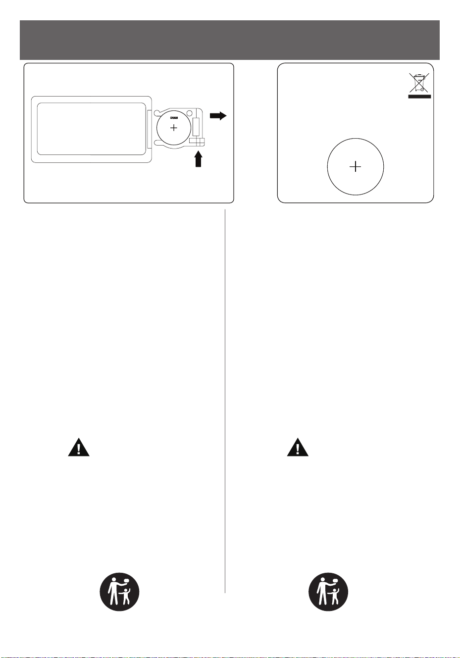
• Immediately dispose of usedbatteries and keep
away from children. Do NOT dispose of batteries in
household trash.
• Even used batteries may cause severe injury or
death.
• Call a local poison control center for treatment
information.
• Compatible battery type - CR2025.
• Nominal voltage 3.0V.
• Do not mix old and new batteries, different brands
or types of batteries, such as alkaline, carbon-zinc,
or rechargeable batteries.
• Ensure the batteries are installed correctly
according to polarity (+ and -).
• Remove and immediately discard batteries from
equipment not used for an extended period of
time.
• Non-rechargeable batteries are not to be
recharged.
• Do not force discharge, recharge, disassemble,
heat above 80°C or incinerate. Doing so may
result in injury due to venting, leakage or explosion
resulting in chemical burns.
WARNING
• INGESTION HAZARD: This product contains a
button cell or coin battery.
• DEATH or serious injury can occur if ingested.
• A swallowed button cell or coin battery can cause
Internal Chemical Burns in as little as 2 hours.
• KEEP new andused batteries OUT OF REACH OF
CHILDREN.
• Seek immediate medical attention if a battery is
suspected to be swallowed or inserted inside any
part of the body.
• Deseche inmediatamente las pilas usadas y
manténgalas fuera del alcance de los niños. NO tire
las pilas junto con los residuos domésticos.
• Incluso las pilas usadas pueden causar lesiones
graves o la muerte.
• Llame a un centro de toxicología local para obtener
información sobre el tratamiento.
• Tipo de pila compatible: CR2025
• Voltaje nominal: 3.0V.
• No mezcle pilas nuevas y usadas, ni pilas de marcas
o tipos diferentes, como las alcalinas, las de carbono
y zinc o las recargables.
• Asegúrese de que las pilas estén instaladas
correctamente según la polaridad (+ y -).
• Retire las pilas de los equipos que no vaya a utilizar
durante un tiempo prolongado y deséchelas
inmediatamente.
• Las pilas no recargables no deben recargarse.
• No fuerce la descarga, no las recargue, no las
desmonte, no las coloque a temperatura de más
de 80°C ni las incinere. De lo contrario, podrían
producirse lesiones debido a la ventilación, fugas o
explosiones que provoquen quemaduras químicas.
ADVERTENCIA
• Peligro en caso de ingestión: Este producto contiene
una pila plana o una pila de botón.
• En caso de ingestión, pueden producirse lesiones
graves, o incluso la muerte.
• La ingestión de una pila plana o de botón puede
provocar quemaduras químicas internas en tan solo
2horas.
• Mantenga las pilas nuevas y usadas fuera del
alcance de los niños.
• Acuda inmediatamente al médico si sospecha que
se ha tragado una pila o si esta ha ingresado en
cualquier parte del cuerpo.
BATTERY REPLACEMENT
REEMPLAZO DE BATERÍA
1pcs CR2025 included
Se incluye 1 batería CR2025
NOTE: Battery disposal
Please always dispose of batteries at
suitable recycling point
NOTA: eliminación de las baterías
Siempre elimine las baterías en un
punto de reciclaje adecuado.
CR2025

63
28WM7145 REV1.0
1-YEAR LIMITED WARRANTY
GARANTÍA LIMITADA DE 1 AÑON
The manufacturer warrants that your new Electric
Fireplace is free from manufacturing and material
defects for a period of one years from date of purchase,
subject to the following conditions and limitations.
1. Install and operate this appliance in accordance
with the installation and operating instructions
furnished with the product at all times. Any
unauthorized repair, alteration, willful abuse, accident,
or misuse of the product shall nullify this warranty.
2. This warranty is non-transferable, and is made to the
original owner, provided that the purchase was made
through an authorized supplier of the product.
3. The warranty is limited to the repair or replacement
of part(s) found to be defective in material or
workmanship,
provided that such part(s) have been subjected
to normal conditions of use and service, after said
defect is conrmed by the manufacturer’s inspection.
4. The manufacturer may, at its discretion, fully
discharge all obligations with respect to this warranty
by refunding the wholesale price of the defective
part(s).
5. Any installation, labor, construction, transportation, or
other related costs/expenses arising from defective
part(s),
repair, replacement, or otherwise of same, will not be
covered by this warranty, nor shall the manufacturer
assume responsibility for same.
6. The owner/user assumes all other risks, if any,
including the risk of any direct, indirect or
consequential loss or
damage arising out of the use, or inability to use the
product, except as provided by law.
7. All other warranties – expressed or implied –with
respect to the product, its components and
accessories, or any
obligations/liabilities on the part of the manufacturer
are hereby expressly excluded.
8. The manufacturer neither assumes, nor authorizes
any third party to assume on its behalf, any other
liabilities with respect to the sale of the product.
9. The warranties as outlined within this document do
not apply to non accessories used in conjunction
with the
installation of this product.
10. This warranty gives you specic legal rights, and you
may also have other rights which vary from state to
state.
El fabricante garantiza que su nueva estufa eléctrica no
presentará defectos de fabricación ni materiales durante
un período de 1 año a partir de la fecha de compra,
siempre y cuando se cumplan las siguientes condiciones
y limitaciones.
1. Esta estufa eléctrica se debe instalar y operar en
todo momento de acuerdo con las instrucciones
de instalación y operación proporcionadas con
el producto. Cualquier reparación no autorizada,
alteración, abuso deliberado, accidente o uso
inadecuado del producto anulará esta garantía.
2. Esta garantía no es transferible y sólo está disponible
para el propietario original, siempre y cuando la
compra se haya realizado a través de un proveedor
autorizado del producto.
3. Esta garantía se limita a la reparación o reemplazo
de piezas que se consideren defectuosas en material
o mano de obra, siempre y cuando dicha pieza haya
estado sometida a condiciones normales de uso y
servicio, después de que una inspección por parte
del fabricante conrme dicho defecto.
4. El fabricante podrá, bajo su criterio, eximirse de toda
obligación respecto de esta garantía reembolsando
el precio al por mayor de la pieza defectuosa.
5. Esta garantía no cubre·ningún costo de instalación,
mano de obra, fabricación, transporte o de otro tipo
que surja de la pieza defectuosa, su reparación,
reemplazo u otra situación, y el fabricante no asume
ninguna responsabilidad por las mismas.
6. El dueño/usuario asume todos los riegos, si los hay,
incluidos los riesgos de daños o pérdidas directos,
indirectos o resultantes que surjan del uso del
producto, o de la incapacidad para usarlo, salvo que
la ley estipule lo contrario.
7. Mediante el presente, se excluye expresamente
cualquier otra garantía, expresa o implícita, respecto
del producto, sus componentes y accesorios, o
cualquier otra obligación o responsabilidad de parte
del fabricante.
8. El fabricante no asume ni autoriza a ningún tercero a
asumir en su nombre ninguna otra responsabilidad
respecto de la venta de este producto.
9. Las garantías descritas en este documento no se
aplican a accesorios que no sean del fabricante
y que se usen junto con la instalación de este
producto.
10. Esta garantía le otorga derechos legales especícos,
pero también puede tener otros derechos que varían
según el estado.

This warranty is void if:
a. The replace is subjected to prolonged periods of
dampness or condensation.
b. Any unauthorized alteration, willful abuse, accident,
or misuse of the product.
c. You do not have the original receipt of purchase.
Esta garantía es nula si:
a. La chimenea está sometida a períodos
prolongados de humedad o condensación.
b. Se produce cualquier alteración no autorizada,
abuso deliberado, accidente o uso inadecuado del
producto.
c. Usted no tiene el recibo original de compra.
CUSTOMER SERVICE
SERVICIO AL CLIENTE
tsicustomerservice.com
For Customer Service Call
1-866-661-1218
Questions?
Our Customer Service department is available Monday –
Friday 8:30 am – 5:30 pm EST.
We can help you with assembly and if necessary, replace
damaged/missing parts.
tsicustomerservice.com
Para el servicio de atención al cliente llame
1-866-661-1218
¿Tiene preguntas?
Nuestro departamento de Servicio al Consumidor
está disponible de Lunes a Viernes, de 8:30 am hasta
las 5:30 pm EST.
Le podemos ayudar con ensamblaje y si es
necesario con el reemplazo de piezas dañadas o
pérdidas.
IMPORTANTE:
Antes de comunicarse con atención al cliente,
tenga disponible la siguiente información:
• Número de serie
• Número de modelo
• Recibo de compra o prueba de compra
tsicustomerservice.com
© 2023, Twin-Star International, Inc. Boca Raton, FL 33487
1-866-661-1218
IMPORTANT:
Before contacting Customer Service, please have this
information available:
• Serial Number
• Model Number
• Sales Receipt or Proof of Purchase