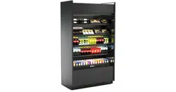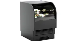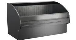
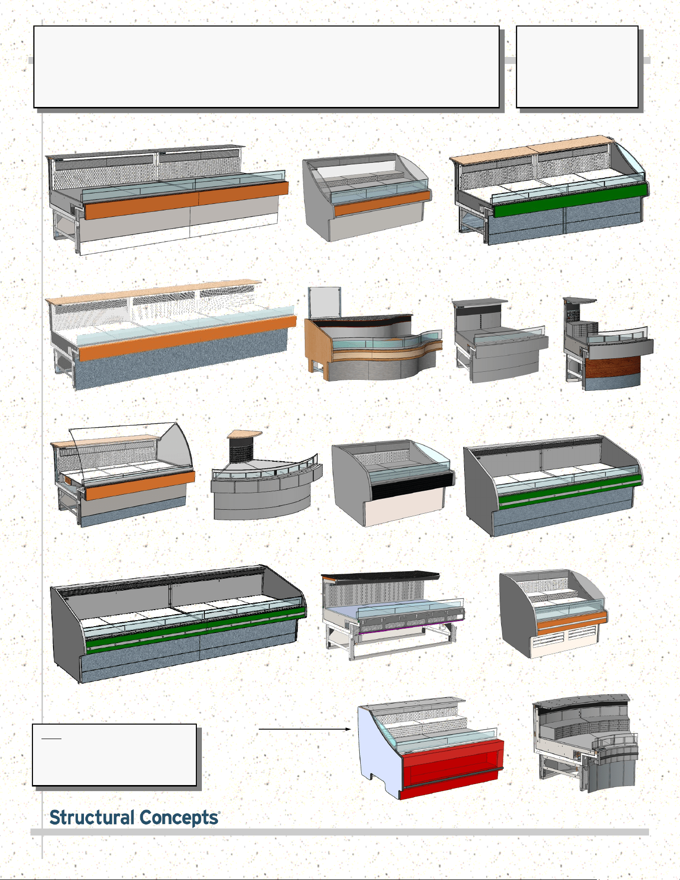
SELF-SERVICE* REFRIGERATED SINGLE DECK MERCHANDISERS
USER MANUALS\5-7277_FUSION_USER MANUAL_GLDSS_GLSS_REF_SELF-SVC_SINGLE DECK_CASE Rev AD: 10/24/2022
GLSS6R.4957 (*Service Case)
GLSSX9R.4934
& GLSSX9R.4959
GLDSS12R.5070D
GLDSS8R.5070B
GLDSS6R.5322
(With Optional Risers)
GLDSS4R
GLDSS10R.5240
GLDSSX239R
GLDSS443R
(With Optional Risers)
Note: See MODEL APPLICABILITY
section in this manual for a list of
models represented by this manual.
This manual may be applicable to
models not listed herein.
GLSS8R.4960
GLDSS9036RG.5655
GLSS12R.4935 & GLSS12R.4958
GLDSS6R.5070A
GLDSSX439R.6145
(With Standard Riser)
GLDSSN439R.6145
GLDSS539R.6145
(With Optional Risers)
SCC P/N
5-7277
USER
MANUAL
FUSION
CAREFULLY FOLLOW THESE INSTRUCTIONS
Structural Concepts Corp. ∙ 888 E. Porter Rd ∙ Muskegon, MI 49441 Phone: 231.798.8888 Fax: 231.798.4960 ∙ www.structuralconcepts.com
2
TABLE OF CONTENTS
TABLE OF CONTENTS ……………………………………………………………………………………….
MODEL APPLICABILITY ……………………………………………………..............................................
OVERVIEW / TYPE / COMPLIANCE / WARNINGS / PRECAUTIONS / WIRING / PLUGS …………..
SKID REMOVAL ……………………………………………………………………………………………….
INSTALLATION: POSITIONING / ALIGNING / FRAME SUPPORT RAILS / LEVELERS ...…….….….
INSTALLATION, CONTINUED: CASE ADJOINMENT INSTRUCTIONS …….……………………..…..
ELECTRICAL CONNECTIONS (SELF-CONTAINED vs. REMOTE UNITS) ….…………………..…….
REFRIGERATED REAR STORAGE AREAS (NOT ON ALL MODELS) …………………………………
OPTIONAL REAR ‘PUSH-UP’ WORK COUNTER …………………………………………………..……..
ADJUSTABLE SCALE STAND (GLDSS10R.5255) / REAR OUTLETS (GLDSS443R.5951) …………
START-UP AND OPERATION …...…...…..…………………………...………….……...….……………...
MAINTENANCE FUNDAMENTALS: EVAP. FANS, TXV, DRAIN ACCESS, RISERS (AKA “STEPS”)
MAINTENANCE FUNDAMENTALS: TEMPERTURE CONTROLLER, MAIN POWER SWITCH …….
MAINTENANCE FUNDAMENTALS: OPTIONAL CLEAN SWEEP CONDENSER COIL ……………...
MAINTENANCE FUNDAMENTALS: REFRIG. PKG. LAYOUT (FROM MODEL GLDSS443R) ……...
MAINTENANCE FUNDAMENTALS: REFRIG. PKG LAYOUT (FROM MODEL GLDSS1243R) ……..
MAINTENANCE FUNDAMENTALS: REFRIG. PKG LAYOUT (SAMPLE ELECTRIC COIL UNIT) …..
HONEYCOMB AIR DIFFUSERS (SERVICE TECHNICIANS ONLY) …………………………………….
START-UP & OPERATION - THERMO-SIMPLE 2 (TS.2) DIGITAL THERMOMETER ALARM ……...
SERIAL LABEL INFORMATION & LOCATION ..……...…………………..…………………..…….….…..
CLEANING SCHEDULE (TO BE PERFORMED BY STORE PERSONNEL) ………...…..……...….....
AVONITE SURFACE CLEANING, CARE & MAINTENANCE …..………..………..….………………….
CLEANING SCHEDULE: STAINLESS STEEL (TO BE PERFORMED BY STORE PERSONNEL) ….
BUTCHER BLOCK CLEANING INSTRUCTIONS (TO BE PERFORMED BY STORE PERSONNEL)
CAESARSTONE® SOLID SURFACE (TO BE PERFORMED BY STORE PERSONNEL) …………...
PREVENTIVE MAINTENANCE (TO BE PERFORMED BY TRAINED SERVICE PROVIDER) …..…..
TROUBLESHOOTING (TO BE PERFORMED BY TRAINED SERVICE PROVIDERS ONLY) …….....
TROUBLESHOOTING - CONDENSING SYSTEM (BY TRAINED SERVICE PROVIDERS ONLY) ….
TROUBLESHOOTING - EVAPORATOR SYSTEM (BY TRAINED SERVICE PROVIDERS ONLY) ....
PROGRAMMABLE CONTROLLER INFORMATION …...………………………..……………….……....
TECHNICAL SERVICE CONTACT INFORMATION / WARRANTY INFORMATION …….…..............
2
3
4-5
6
7
8
9
10
11
12
13
14
15
16
17
18
19
20-21
22-23
24
25
26
27
28
29
30-31
32-34
35
36
37
38
3
MODEL APPLICABILITY
This Operating Manual is Generally Applicable To The Following G-Series
Self-Service Refrigerated Single Deck Merchandiser Models:
GLDSSN2R GLDSSN4R GLDSSN9R GLDSS23239R GLDSS439R GLDSS443R GLDSS443R.5951
GLDSS543R GLDSS543R.5951A GLDSS639R GLDSS639R.6145 GLDSS643R GLDSS839R
GLDSS839R.6145 GLDSS839R.6851D GLDSS843R.5951C GLDSS9036RG.5655 GLDSS1039R
GLDSS1043R GLDSS1043R.5951D GLDSS1239R GLDSS4R GLDSS4R.5070 GLDSS4R.5322B
GLDSS4R.5454 GLDSS5R GLDSS6R GLSS6R.4933 GLSS6R.4957 GLDSS6R.5069 GLDSS6R.5070
GLDSS6R.5179 GLDSS6R.5238 GLDSS6R.5322 GLDSS6R.5454A GLDSS8R GLDSS8R.5070B
GLDSS8R.5178 GLDSS8R.5245 GLDSS8R.5322A GLDSS8R.5454B GLDSS8R.5454SB
GLDSS8R.6022 GLDSS12R.5070D GLDSS12R.5375 GLDSS12R.5454D GLDSS843R
GLDSS843R.5440 GLDSS1243R GLDSSN439R.6145 GLDSSN943R.5951H GLDSSX2R GLDSSX4R
GLDSSX9R GLDSSX9R.5239 GLDSSX9R.5323 GLSS8R.4960 GLDSS10R.5454C GLSS12R.4935
GLSS12R.4958 GLDSS12R.5454D GLDSSX4R.6024 GLSSX9R.4934 GLSSX9R.4959 GLSSX9R.5177
GLDSSX9R.5239 GLDSSX9R.5454AA GLDSSX9R.6023 GLDSSX239R GLDSSX239R.6145
GLDSSX439R.6145 GLDSSX443R GLDSSX939R.6145 GLDSS336R.6145 GLDSS539R.6145
GLDSSX943R GLDSSX940R.5570 GMDS6R.5241 GMDS10R.5243 GMDS10R.5255 SO96R.5440
4
OVERVIEW
• These Structural Concepts cases are designed to
merchandise packaged products at 41 °F (5 °C) or less
product temperatures (unless custom cases with wire
rack shelving).
• Product must be pre-chilled to 41 °F (5 °C) or less before
being placed in merchandiser.
• Cases should be installed and operated according to this
operating manual’s instructions to ensure proper
performance. Improper use will void warranty.
TYPE 1 vs. TYPE 2 CONDITIONS
This unit is designed for the display of products in ambient
store conditions where temperatures and humidity are
maintained within a specific range.
• Type 1 conditions: ambient conditions are to be 55%
max. humidity and 75 °F (24 °C) max. temperature.
• Type 2 conditions: ambient conditions are to be 60%
max. humidity and 80 °F (27 °C) max. temperature.
• If unsure if unit is Type 1 or 2, see tag next to serial label.
See SERIAL LABEL LOCATION & INFORMATION
LISTED / TECH INFO & SERVICE section in this manual
for sample serial labels).
COMPLIANCE
• Performance issues when in violation of applicable
NEC, federal, state and local electrical and plumbing
codes are not covered by warranty.
• See below compliance guideline.
WARNINGS
• This page contains important warnings to prevent injury or
death. Please read carefully!
PRECAUTIONS and WIRING DIAGRAMS
• See next page for PRECAUTIONS and WIRING
DIAGRAM information.
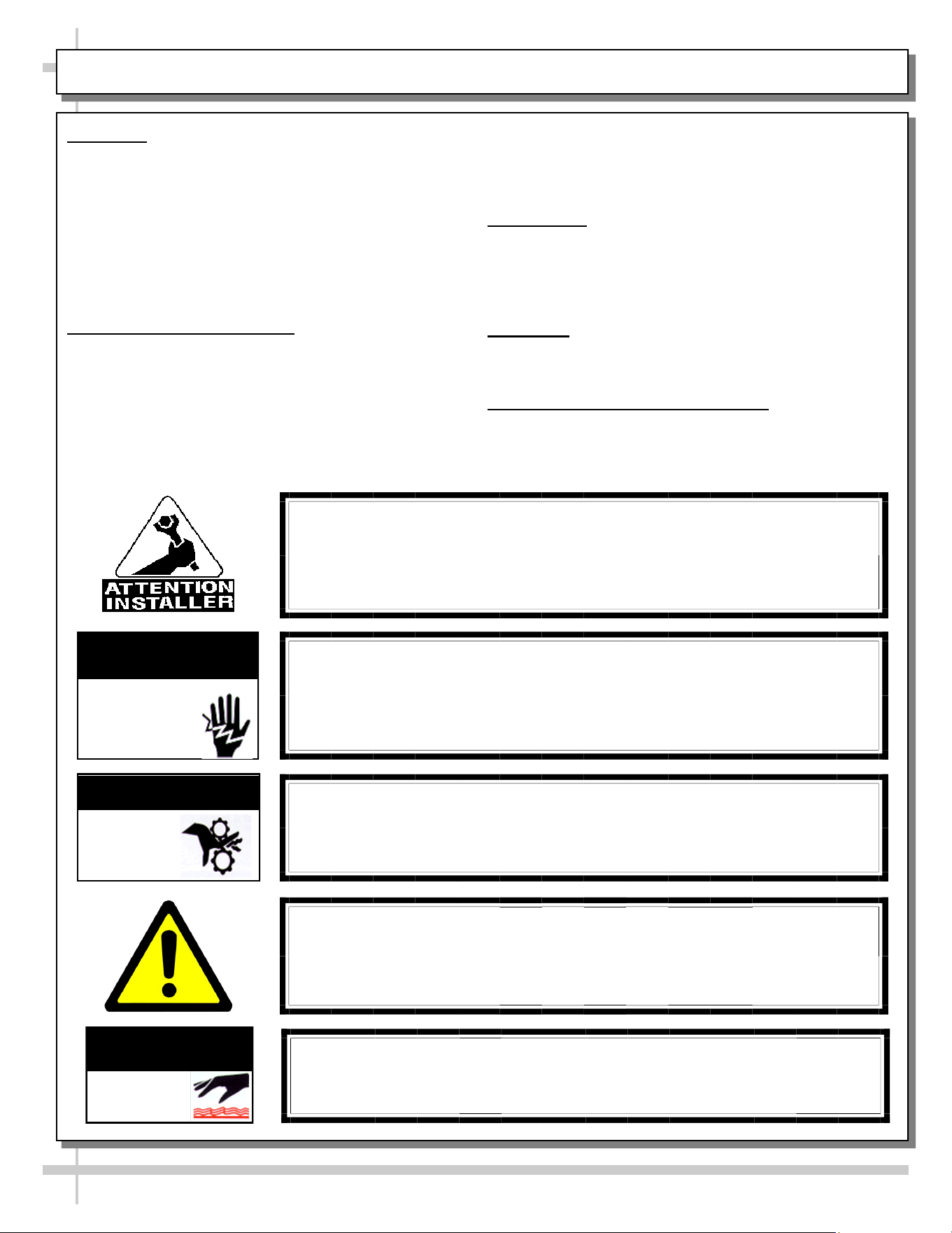
WARNING
Hazardous moving parts. Do not operate unit with covers removed.
Fan blades may be exposed when deck panel is removed.
Disconnect power before removing deck panel.
WARNING
Risk of electric shock. Disconnect power before servicing unit.
CAUTION! More than one source of electrical supply is
employed with units that have separate circuits.
Disconnect ALL ELECTRICAL SOURCES before servicing.
WARNING
ELECTRICAL
HAZARD
WARNING
KEEP
HANDS
CLEAR
COMPLIANCE
This equipment MUST be installed in compliance with
all applicable NEC, federal, state and local
electrical and plumbing codes.
OVERVIEW / TYPE / COMPLIANCE / WARNINGS / PRECAUTIONS / CORDS / WIRING - PAGE 1 of 2
WARNING
This product can expose you to chemicals, including
Urethane (Ethyl Carbamate), which are known to the state of
California to cause cancer and birth defects or other reproductive
harm. For more information go to P65Warnings.ca.gov.
WARNING
Condensate pan and overflow condensate pans are HOT!
Disconnect and allow to cool before cleaning or removing from case.
WARNING
HOT
SURFACE
PRECAUTIONS
• Following are important precautions to prevent damage
to unit or merchandise. Read carefully!
• See previous page for specifics on OVERVIEW,
CONDITION TYPE, COMPLIANCE and WARNINGS.
WIRING DIAGRAM
• Each case has its own wiring diagram folded and in its
own packet. It may be placed near ballast box, field
wiring box, raceway cover, or other related location.
REFRIGERANT DISCLOSURE STATEMENT
• This equipment is prohibited from use in California with
any refrigerants on the “List of Prohibited Substances” for
that specific end-use, in accordance with California Code
of Regulations, title 17, section 95374.
• This disclosure statement has been reviewed and
approved by Structural Concepts and Structural Concepts
attests, under penalty of perjury, that these statements
are true and accurate.
OVERVIEW / TYPE / COMPLIANCE / WARNINGS / PRECAUTIONS / CORDS / WIRING - PAGE 2 of 2
5
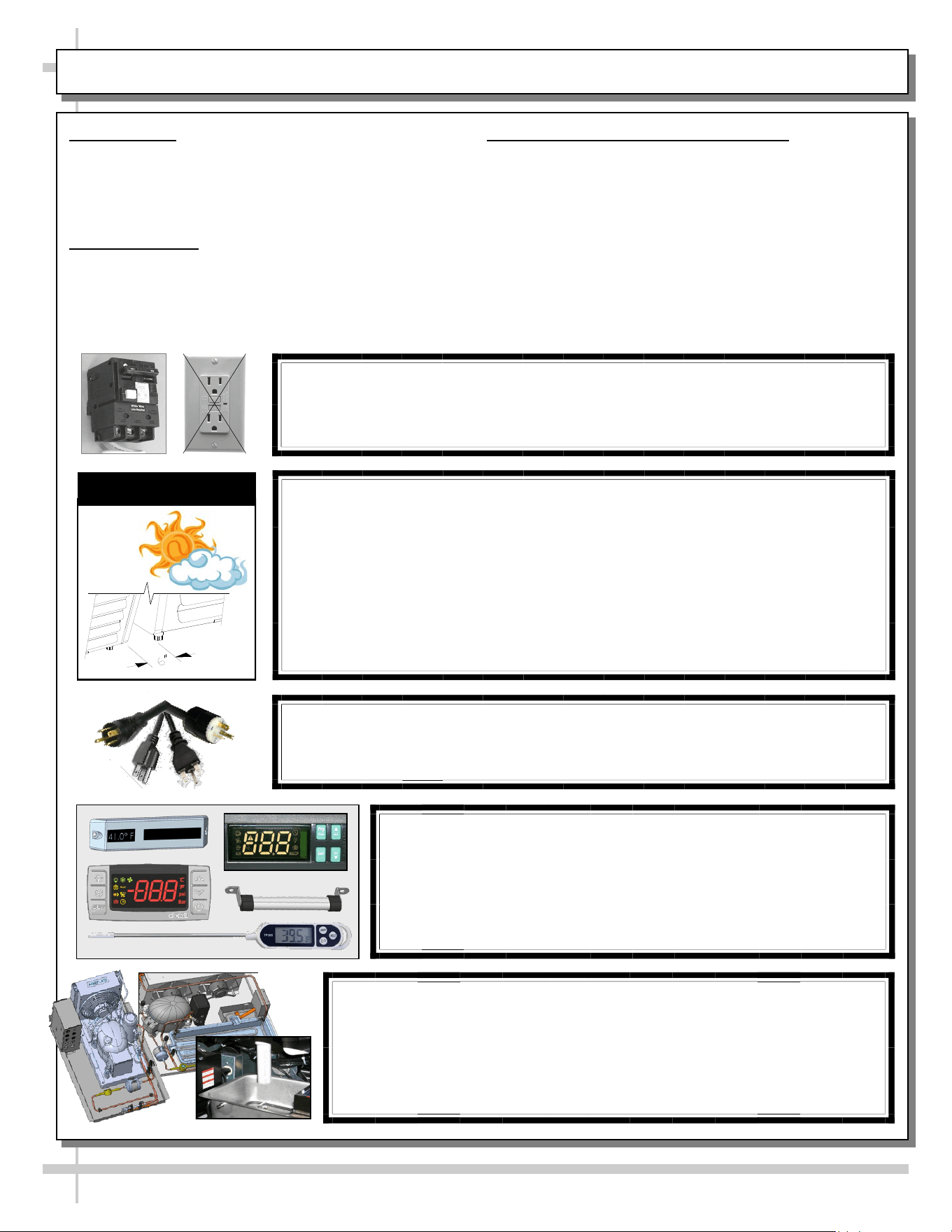
CAUTION! POWER CORD AND PLUG MAINTENANCE
Risk of electric shock. If cord or plug becomes damaged,
replace only with cord and plug of same type.
CAUTION! GFCI BREAKER REQUIREMENT
If N.E.C. (National Electric Code) or your local code
requires GFCI (Ground Fault Circuit Interrupter) protection,
you MUST use a GFCI breaker in lieu of a GFCI receptacle.
CAUTION! ADVERSE CONDITIONS / SPACING ISSUES
• Performance issues caused by adverse conditions are NOT warranted.
• To prevent damage to end panels due to condensation, apply industrial grade
silicone sealant and tightly join to opposite end panels. When not adjoining
cases, keep end panels at least 6” away from walls/structures. Rear panels
must also be kept at least 6” from walls and structures.
• Case must not be exposed to direct sunlight or any heat source.
• To maintain proper case temperature, keep case at least 15-feet from exterior
doors, overhead HVAC vents or any air curtain disruption.
• Self-contained case clearance: 6” min. air intake / 6” min. air discharge.
CAUTION
CAUTION! DO NOT RELY ON THERMOMETERS OR
THERMOSTATS FOR PRODUCT (FOOD) TEMPERATURES.
• Thermometers & thermostats reflect air temperatures ONLY.
• For ACTUAL product (food) temperatures, use a calibrated food
probe thermometers ONLY.
• For accurate readings, DO NOT use infrared food thermometers.
CAUTION! CHECK CONDENSATE PAN, ITS POSITION & PLUG!
Water on flooring can cause extensive damage!
• Before powering up case, check that condensate pan is positioned
directly under case’s condensate drain.
• Before powering up case, check that condensate pan’s electrical plug is
SECURELY connected to condensate system’s receptacle.
• If wicking material is used in condensate pan, check that it is secure.
6
REMOVAL FROM SKID
Note: Units shown may
not depict an exact
representation of your
particular unit being installed.
6
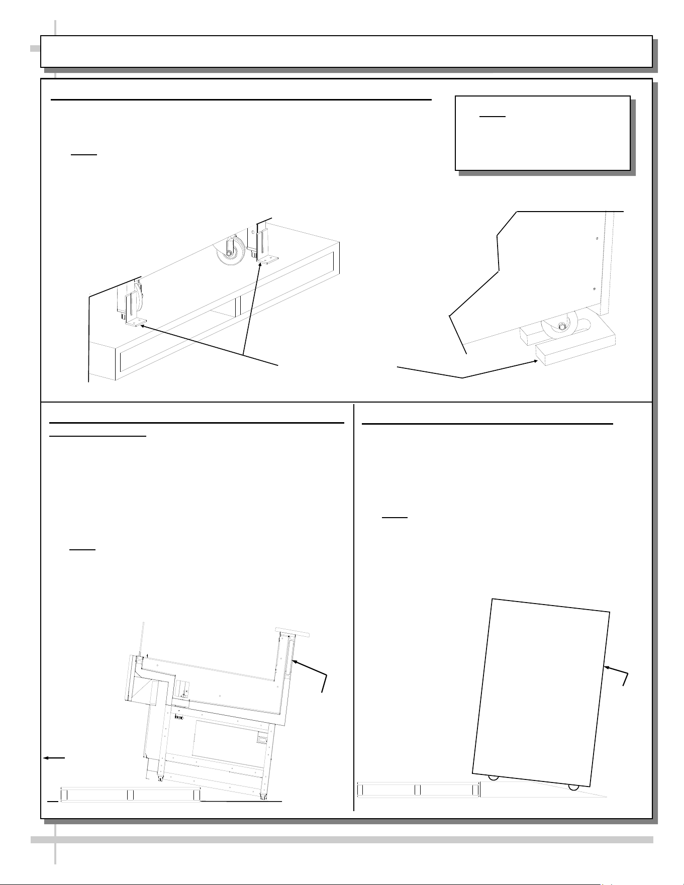
CASE REMOVAL FROM SKID (CASTERS, LEVELERS OR FRAME SUPPORT RAILS)
Various Types Of
Case Shipping
Brackets
1. Removing Case Shipping Brackets That Are Attached To Skid
• Remove screws holding Case Shipping Brackets to skid.
• Remove Case Shipping Brackets from Skid.
• See illustrations below.
• Note: Shipping Brackets will vary in size, shape, material and
location depending upon case type and model.
3. Remove Case (With Casters) From Skid
A. Place ramp up against skid (to allow case to
smoothly slide off from skid).
B. Maintain support of case at all times or center
of gravity may cause case to fall.
C. Unlock Casters. Slide unit to rear of skid. Slide
down ramp and off from skid.
• Note: Illustrations reflect general outline of
sample case and may not reflect your particular
model or options).
Support
case
while
sliding
down
ramp.
Ramp
2. Remove Case (With Levelers or Frame Support
Rails) From Skid
• To prevent damage, support case while sliding it
toward edge of skid.
• When case is at edge of skid, carefully lower to
floor so that two levelers (or one frame support
rail) rests on floor.
• Carefully slide skid out from under case.
• After case is off skid, place into position.
• Note: Illustration below reflects general outline of
sample case and does not reflect any particular
model or options).
Carefully
Slide Skid
Out From
Under Case
Support
case
while
removing
from skid
7
INSTALLATION: POSITIONING / ALIGNING / FRAME SUPPORT RAILS / LEVELERS
Note: Units shown may not depict an exact representation of your particular unit being installed.
Pry Bar
Base
Frame
Leveler
Adjustable
Wrench
Toe-Kick
1. Position & Align Case Alongside Other Cases
• Before adjusting levelers (or shimming frame
support rails), make certain that the case is in
proper position and, if required, aligned with
adjoining case.
• This may require the repositioning of the case
you are installing or the already positioned
case.
2. Cases With Frame Support Rails: Shim
• Illustration at top right shows case with frame
support rails.
• Shims will be provided with all cases that have
frame support rails.
• Use shims to level case.
• Note: After case is in position, it must be
sealed to floor to prevent entry or leakage
of liquid or moisture.
3. Cases With Levelers: Adjust Levelers
• After case is in position, adjust case so it is level
and plumb (see illustration at right).
• You may need to remove front and/or rear
Toe-Kick to access levelers.
• Use adjustable wrench (and possibly a pry bar)
to adjust leveler.
• Do not use Pry Bar on Toe-Kick as it may
buckle.
• Do not use Pry Bar on End Panel as it may
chip.
• Use Pry Bar ONLY on Base Frame to avoid
damaging case.
• See illustration and photos below and at lower
right.
Frame Support
Rails
8
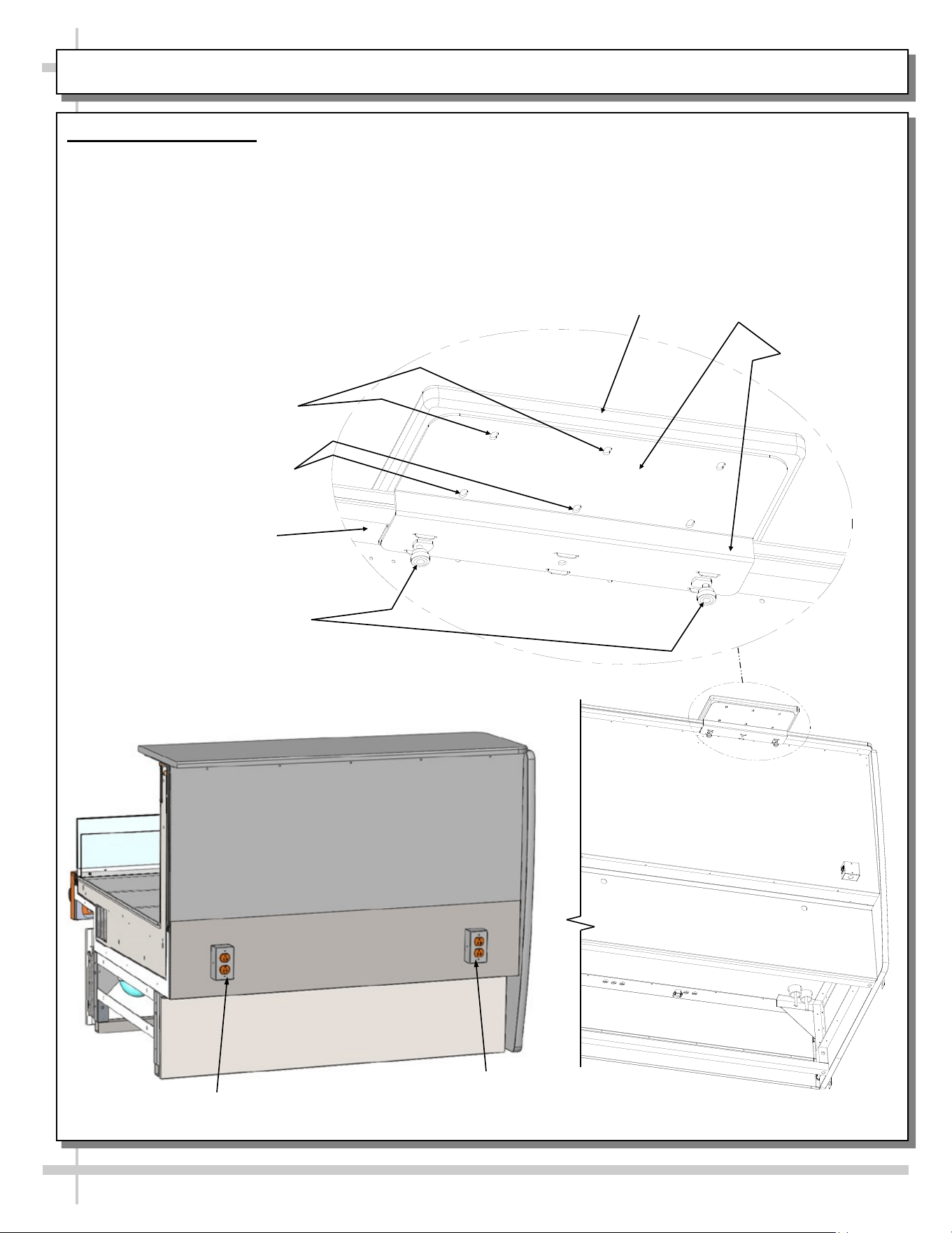
INSTALLATION, CONTINUED: CASE ADJOINMENT INSTRUCTIONS
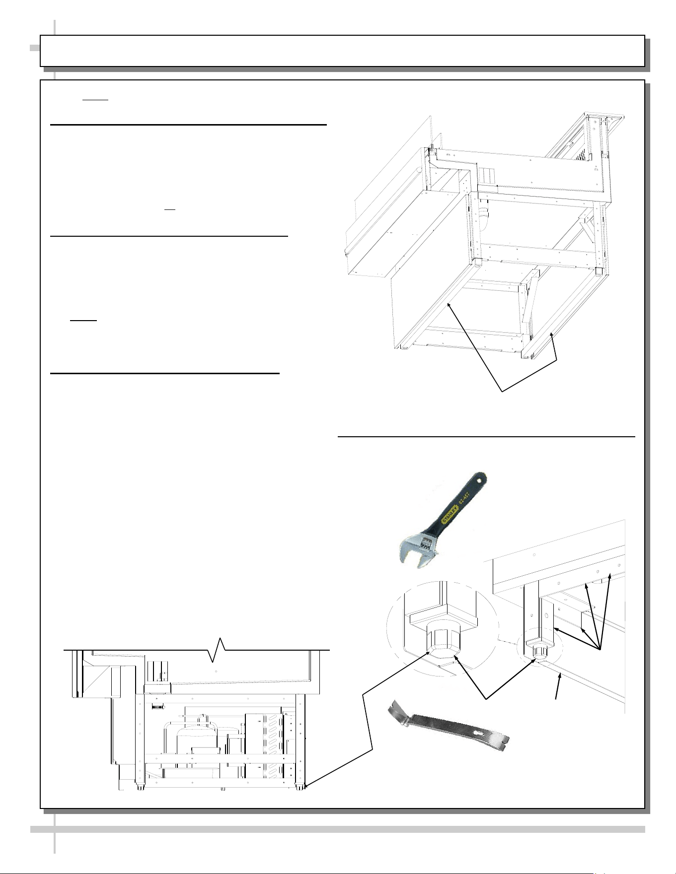
4. Case Adjoinment Instructions
>> Warranty is void if improper caulk/sealant is used.
>> Lay generous beads of caulk/sealant as specified.
A. Prior To Adjoinment - Apply Industrial Butyl
Caulk at Center of Uprights
• Lay a generous bead of industrial grade butyl caulk
at center of uprights (in non-visible areas).
• This butyl caulk prevents refrigerated air from
escaping between cases (causing condensation and
reducing refrigeration efficiency) as well as
preventing ants or other insects from entering case.
• See illustration below.
B. Adjoining Cases - Using Bolts and Nuts
• Use appropriately sized nuts and bolts for each hole.
#1 - Hole is accessible at underside of top surface
support.
#2 - Holes are accessible through rear plenum and
behind honeycomb air diffuser.
#3 - Holes are accessible at underside of decking.
Decking must be removed to attach bolts/nuts.
#4 - Holes are accessible at base frame (through front of
case after front toe-kicks have been removed).
• Tighten nuts securely (but do not over-tighten).
• See accompanying illustration below.
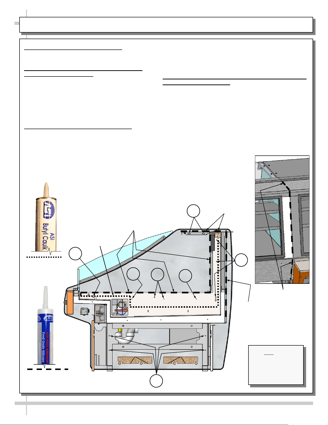
C. After Adjoinment - Apply Food Grade Silicone Sealant
To Inner And Outer Seams
• After all nuts/bolts are securely attached to case, apply a
generous bead of food grade silicone sealant at both
inner and outer adjoinment seams.
• When properly applied, this food grade silicone sealant
will prevent water from seeping between cases (into the
case or to the floor) as well as crumbs or other residue
from entering between case seams.
• See illustrations below.
>> You must reattach toe-kick and decking after case
adjoinment process is complete.
Note: Model
GLDSS539R.6145 Is
Shown at Left. Decking
Has Been Removed
For Illustrated
Purposes Only.
1
2
3
3
3
4
Refrigeration
Bead
Inner Sanitation
Bead
Outer Sanitation
Bead To Be Applied
At Outer
Adjoinment Seams
(Shown Above In
Random Model)
Outer
Sanitation Beads
3
Outer
Sanitation
Bead
Industrial Grade
Butyl Calk (For
Refrigeration Bead
Applications)
Food Grade Silicone
Sealant (For Sanitation
Bead Applications)
9
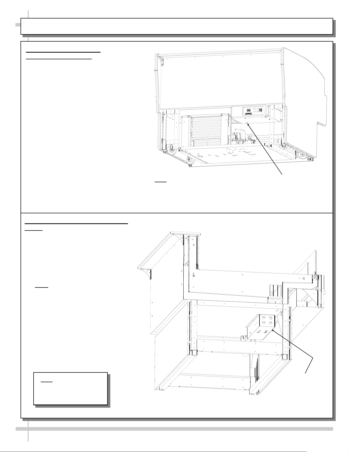
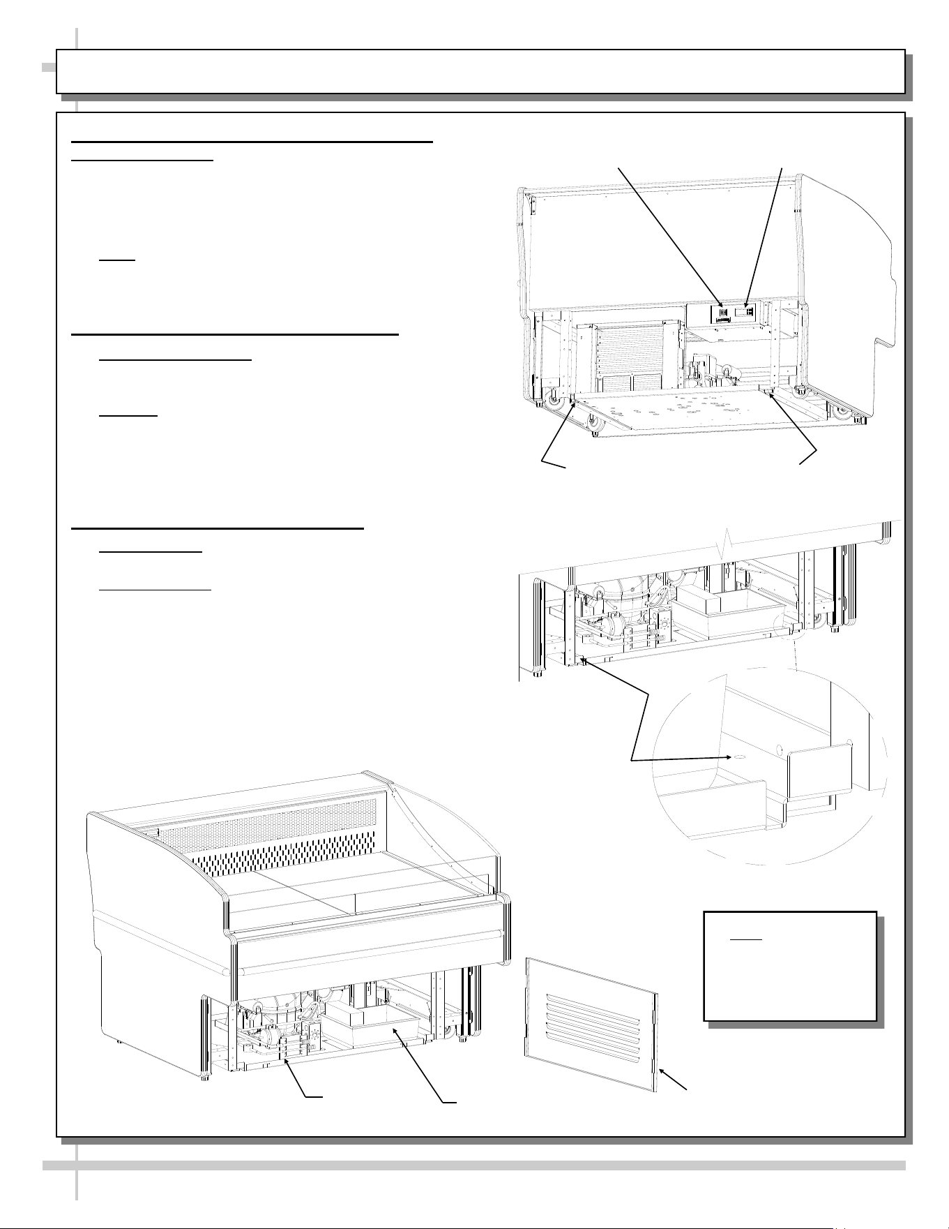
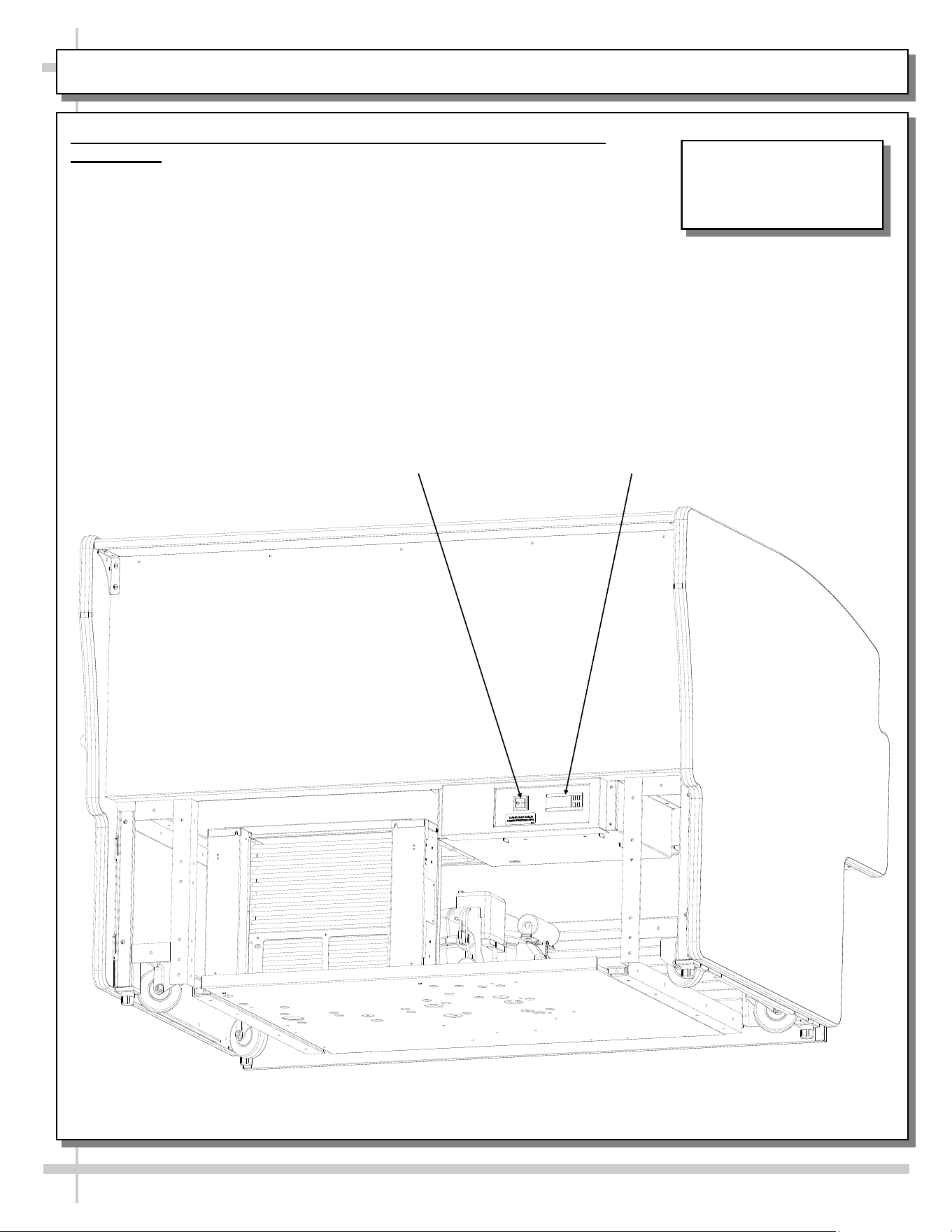
ELECTRICAL CONNECTIONS (SELF-CONTAINED vs. REMOTE UNITS)
1. Electrical Connections
(Self-Contained Units)
Field wiring hook-up/electrical access
locations are shown in illustrations below
(may not exactly reflect your particular unit).
• Single phase leads are provided.
• See Technical Information Sheet for
more information.
2. Electrical Connections (Remote
Units)
Field wiring hook-up / electrical
access locations are shown in
illustrations below (may not reflect
your particular unit).
• Single phase leads are provided.
• See Technical Information Sheet
for more information.
• Note: Illustration at right may not
exactly reflect your particular unit.
Electrical Box
Location
(Remote Units)
Field Wiring Hookup (for
Self-Contained Cases)
Note: Rear of case is shown with
rear grille lifted up and off.
Note: Illustration shown
may not exactly reflect
every feature or option of
your particular case.
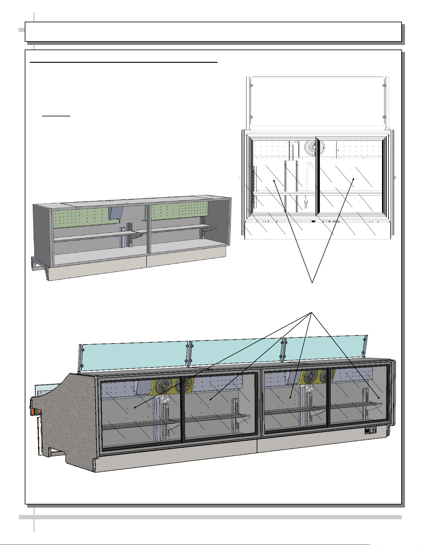
Refrigerated Rear Storage Areas (Not on All Models)
• Refrigerated rear storage area illustrations show
transparent doors (or removed doors) for illustrative
purpose only.
• Most models have rear refrigerated storage part of
standard model.
• Optional: Customer specified rear refrigerated storage
units are entirely separate from merchandiser
(as shown directly below).
• Adjustable shelves and cooling fan(s) are inside storage
area.
• See CLEANING SCHEDULE (TO BE PERFORMED
BY STORE PERSONNEL) section in this manual for
cleaning schedule and procedure.
10
REFRIGERATED REAR STORAGE AREAS (NOT ON ALL MODELS)
Sliding doors on these models are shown
transparent. Depending upon model,
some cases may be opaque.
Model GLDSS12R.5375
Is Shown Above
Optional Refrigerated Supplies Organizer (SO96R.5440)
To Attach to Rear of Customer Specific Cases Only
(e.g. GLDSS843R). Rear Sliding Doors Removed
For Illustrative Purposes Only
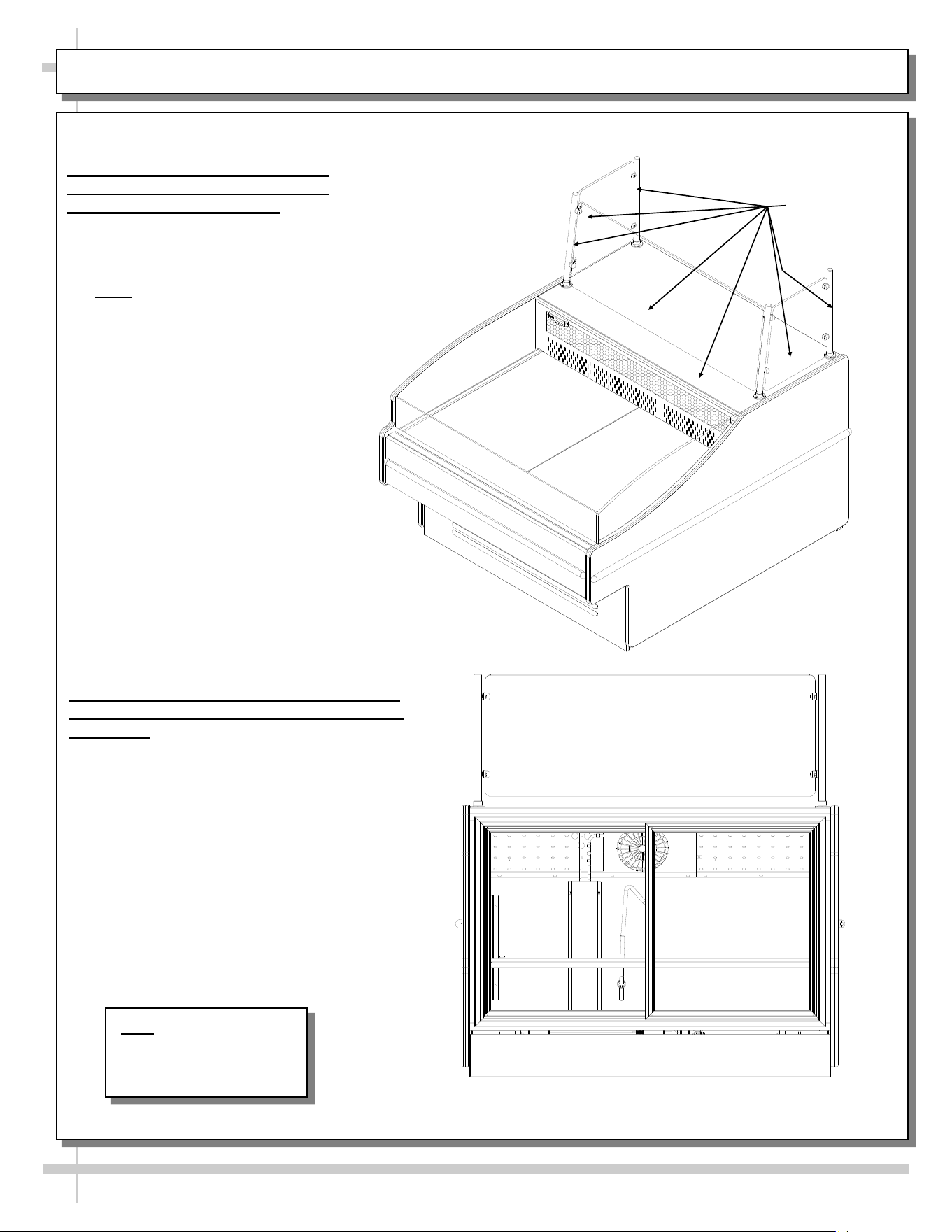
1. Optional Rear ‘Push-up’ Work
Counter (And Its Accompanying
Sneeze Guard’) - ISO View
• View shown at right is illustrated
with optional rear pushup work
counter.
• Note: Illustration at right is of
sample model. Your model will
vary in appearance.
11
OPTIONAL REAR ‘PUSH-UP’ WORK COUNTER
Note: Units shown may not depict an exact representation of your particular unit being installed.
Optional Rear
Pushup Work
Counter
2. Optional Rear ‘Push-up’ Work Counter
(And Its Accompanying ‘Sneeze Guard’) -
Rear View
• View shown at right is of self-contained
unit with optional rear ‘push-up’ work
counter in place.
• Sliding doors will allow access to storage
shelf and allow for refrigeration
maintenance.
Above view shown with sliding doors transparent (for illustrative
purposes only). Sliding doors are not transparent.
Note: Illustrations shown
may not exactly reflect
every feature or option of
your particular case.
12
ADJUSTABLE SCALE STAND (GLDSS10R.5255) / REAR OUTLETS (GLDSS443R.5951)
Thumbscrew (For
Adjustable Scale Stand)
Locking Pad (For
Thumbscrew Pressure)
Adjustable
Scale Stand
Adjustable Scale Stand
• View shown below is illustrated with optional rear
pushup work counter.
• Entire adjustable scale stand may be removed
from case for cleaning purposes. See
CLEANING SCHEDULE (TO BE PERFORMED
Support Bracket
(For Adjustable
Scale Stand)
Outer Retaining Screws (For
Adjustable Scale Stand) Typ.
Inner Retaining Screws (For
Adjustable Scale Stand) Typ.
Model
GLDSS443R.5951
BY STORE PERSONNEL) for instruction on
removing scale stand and cleaning specifics.
• If adjustable scale stand material is butcher block,
see BUTCHER BLOCK CLEANING
INSTRUCTIONS section in this manual.
Rear Outlet
Rear Outlet
Model
GLDSS10R.5255
13
START-UP AND OPERATION
1. Merchandiser Refrigeration Assembly Pan
Slide-Out Feature
• Retaining screws must be removed to allow
refrigeration assembly to be slid out (for servicing
and/or cleaning).
• See illustration at top-right.
• Note: Two addition screws must be removed from
top of rails for pan to slide out allowing refrigeration
assembly access. See illustration at mid-right.
2. Merchandiser Start-Up - Refrigeration
• Self-Contained Only: Before turning on Main Power
switch, remove front panel (by lifting up and off; no
screw removal required).
• Caution! Check that the condensate pan is
positioned directly under the drain BEFORE turning
on Main Power!
• Return front panel to the case in same manner it
was removed. See below illustration.
3. Merchandiser Start-Up - Electrical
• Remote Units: Case is hard-wired. When power is
supplied, case will power-up.
• Self-Contained: Main Power switch is located at
case rear-right. See illustration at top right (rear
panel is removed to show main power switch and
temperature controller).
• Rear panel is designed to be lifted up and off without
screws.
Refrigeration Assembly Pan
Retaining Screws
Temperature
Controller
Front Panel (Lift Up
and Off). No Screw
Removal Required
Condensate Pan
(Electric Coil Evap-
oration Units)
Refrigeration
Package
Main Power Switch
(Self-Contained Only)
Two additional
screws must be
removed from
top of rails for
pan to slide out.
View of Case Front
Note: Illustrations
shown may not exactly
reflect every feature
or option of your
particular case.
14
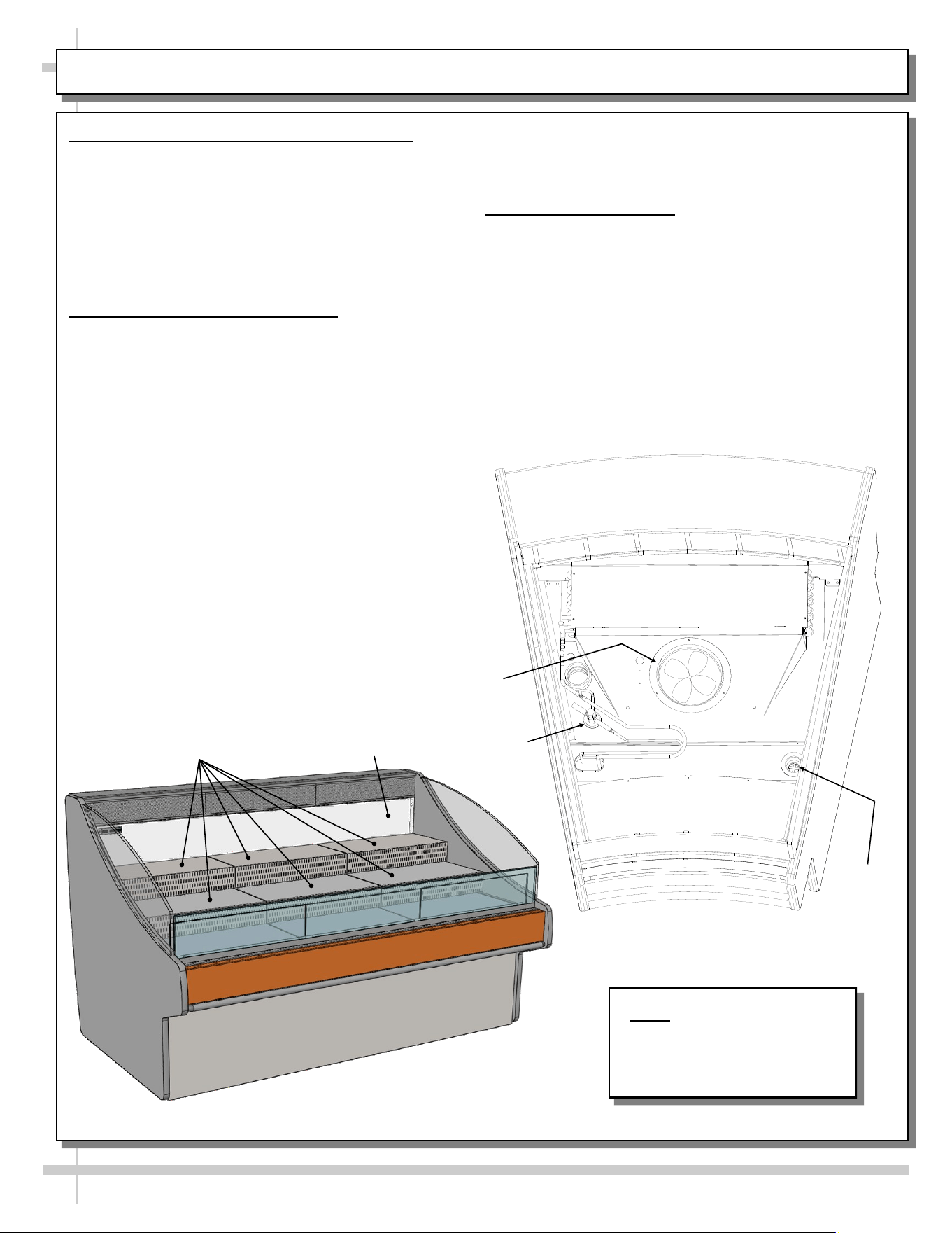
1. Evaporator Fans, TXV and Drain Access
• Caution! Turn Main Power off and disconnect
from outside power source.
• Remove decking and sub-deck.
• Perform maintenance, service or cleaning as
required.
• Return decking and sub-deck to unit in reverse
order in which they were removed.
2. Evaporator Coil Fan Discharge
When main power switch is on, refrigeration
assembly will energize (see START-UP AND
OPERATION section in this operating manual.
• Coil fans should turn on. From inside of the case,
check for discharge air from front baffle, to
confirm that the fans are functioning properly.
Drain
Evaporator
Coil Fan
TXV
MAINTENANCE FUNDAMENTALS: EVAP. FANS, TXV, DRAIN ACCESS, RISERS (AKA “STEPS”)
Note: Illustrations shown
may not exactly reflect
every feature or option of
your particular case.
• When the case is in a start up mode or has been
idle for a long period of time, the unit will require
75 minutes of run time to pull-down temperature.
3. Risers (aka “Steps”)
• Risers (“steps”) allow product to be more
prominently displayed.
• Risers are to rest on decks and be placed as far
back as possible (up against rear plenum).
• See CLEANING SCHEDULE (TO BE
PERFORMED BY STORE PERSONNEL) in
manual for instructions on cleaning risers/steps.
Model GLDSS6R.5322 (With Steps) Shown Above
Rear Plenum
Risers (aka “Steps”)
15
4. Temperature Controller and Main Power Switch (Self-Contained
Units Only)
• Self-Contained units have Temperature Controller in location
shown below.
• Access by removing rear panel. Simply lift up and off (no screw
removal is required).
• See Temperature Controller section of this manual for specifics on
settings & parameters.
• Illustration below has rear panel lifted up and off unit (to allow
access to Main Power Switch and Temperature Controller).
Main Power Switch
(Self-Contained Only)
Temperature
Controller
Above illustration is shown with rear panel removed for illustrative purposes only.
MAINTENANCE FUNDAMENTALS: TEMPERTURE CONTROLLER, MAIN POWER SWITCH
Note: Illustration shown
may not exactly reflect
every feature or option of
your particular case.
16
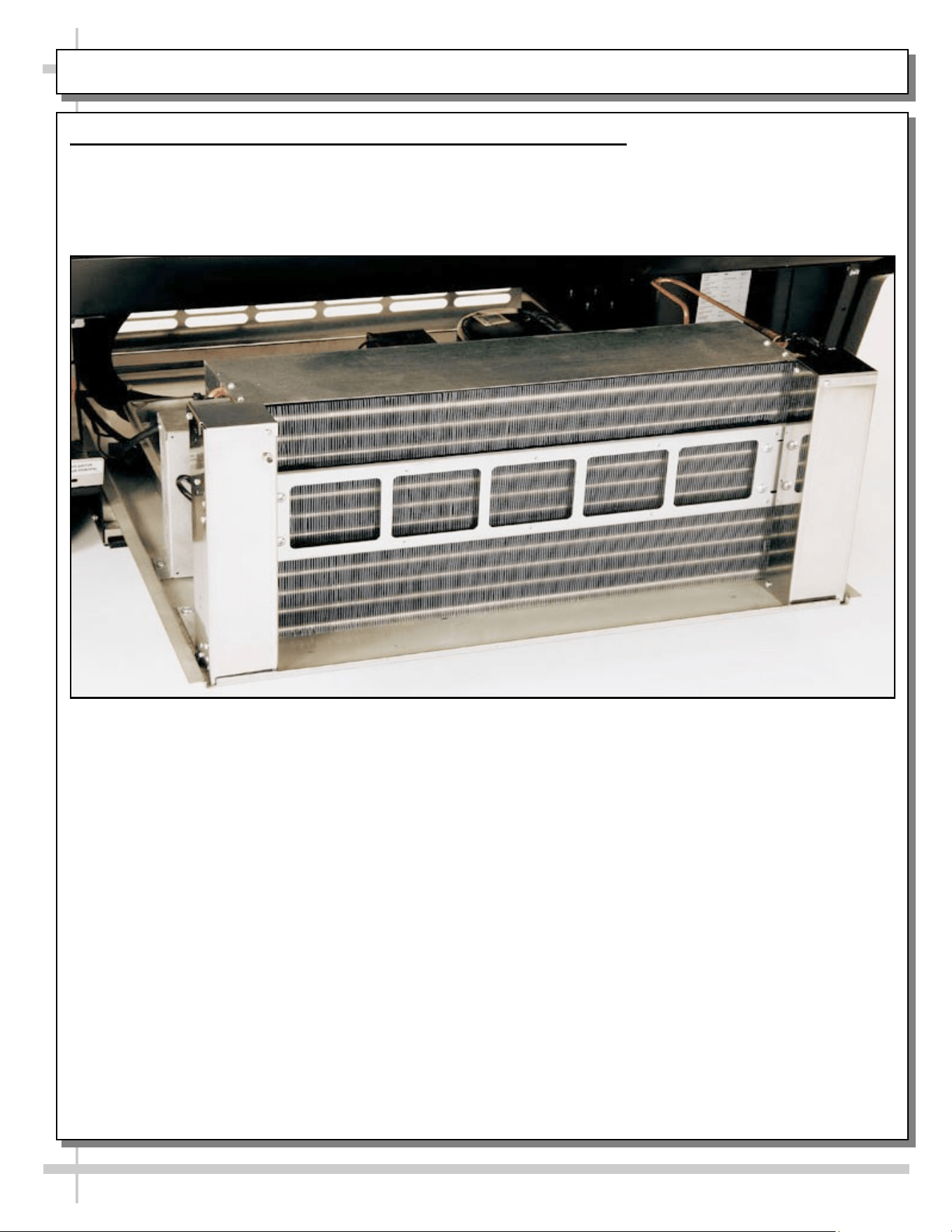
MAINTENANCE FUNDAMENTALS: OPTIONAL CLEAN SWEEP CONDENSER COIL
5. Optional Clean Sweep Condenser Coil (Self-Contained Units Only)
• Clean Sweep Condenser Coil (photo below) is accessible by removing rear grille.
• See Preventive Maintenance (To Be Performed By Trained Service Provider) for cleaning instructions.
• Photo below is after rear grille has been removed case
17
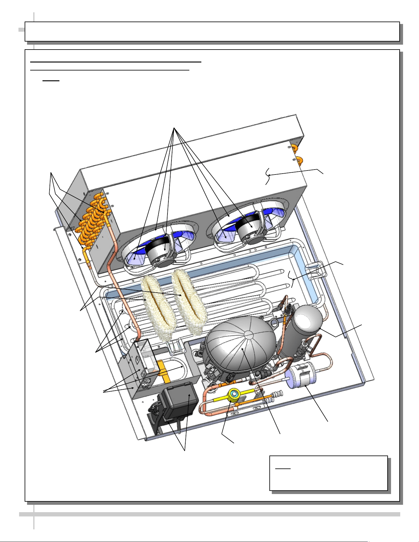
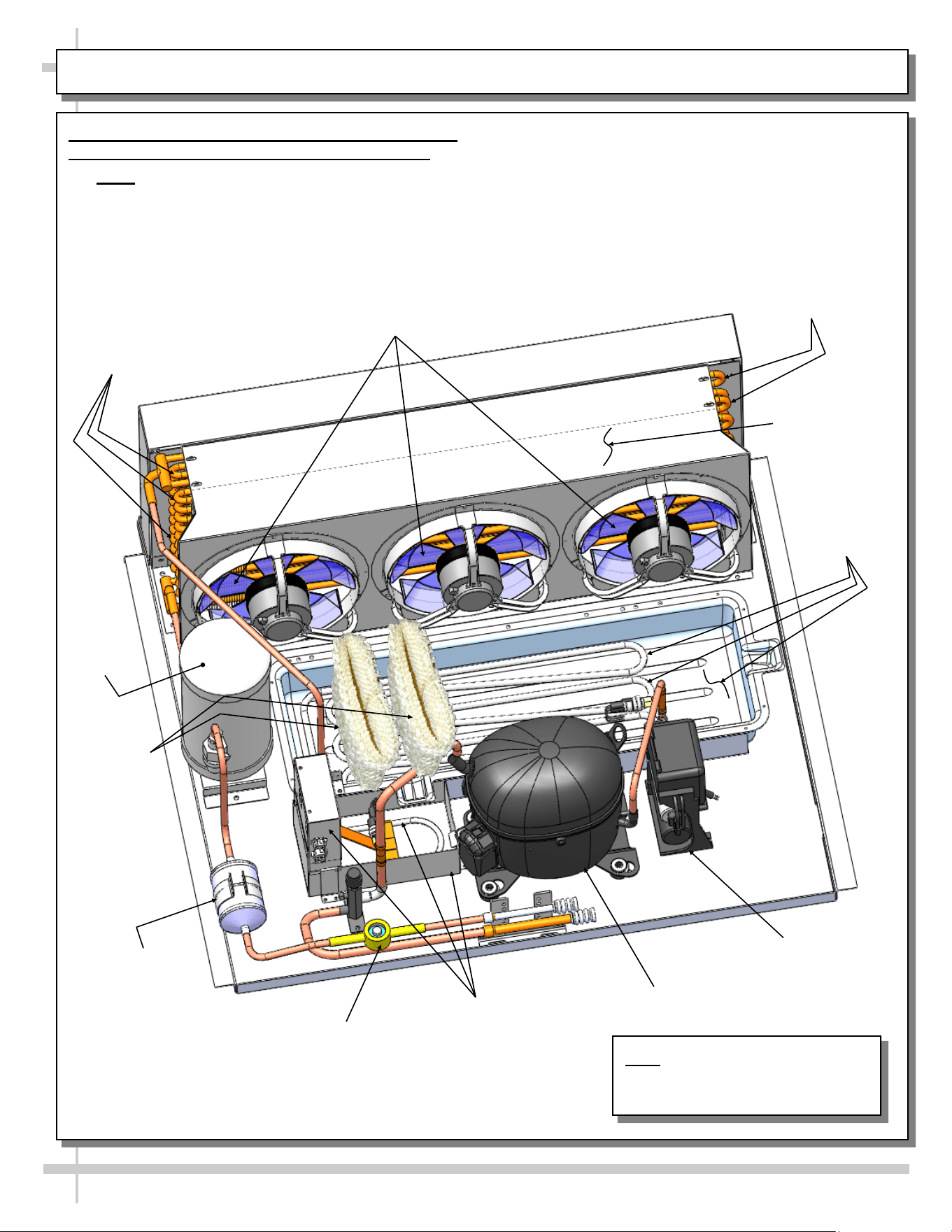
MAINTENANCE FUNDAMENTALS: REFRIGERATION PKG LAYOUT (FROM MODEL GLDSS443R)
Refrigeration
U-Tubes
Filter Dryer
Electrical
Starter Unit
Condenser Coil
Housing
Condenser Coil Fan,
Fan Housing & Motor
Overflow Pan (Under
Overflow Pan
Electrical Box)
Hot Gas Loop
Condensate Pan
6. Refrigeration Package Layout (Hot Gas Loop)
on Model GLDSS443R (and Possibly Others)
• Note: Due to design variables, refrigeration
package component layout can slightly vary
in size and location.
• Refrigeration package shown below reflects
model GLDSS443 (hot gas loop condensate
unit).
• See next page for larger hot gas loop condensate
Hot Gas Loop
Condensate System
Wicking Material
(Optional)
Sight Glass
Compressor
Receiver
Note: Illustrations shown may not
exactly reflect every feature or
option of your particular case.
18
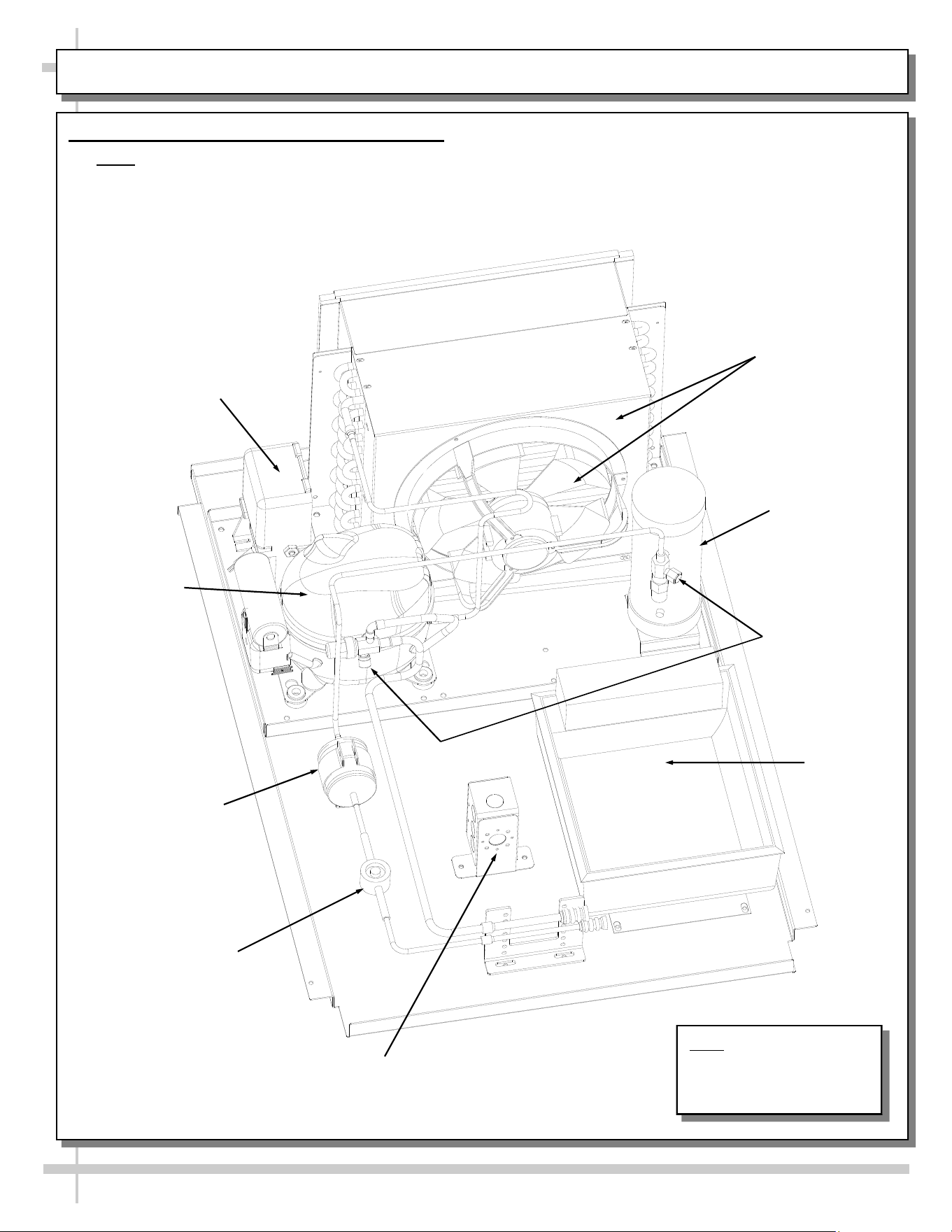
MAINTENANCE FUNDAMENTALS: REFRIGERATION PKG LAYOUT (FROM MODEL GLDSS1243R)
Refrigeration
U-Tubes
Filter Dryer
Electrical
Starter Unit
Condenser Coil
Housing
Condenser Coil Fan,
Fan Housing & Motor
Overflow Pan
(And Overflow Pan
Electrical Box)
Hot Gas Loop
Condensate
Pan
7. Refrigeration Package Layout (Hot Gas Loop)
on Model GLDSS443R (and Possibly Others)
• Note: Due to design variables, refrigeration
package component layout can slightly vary
in size and location.
• Refrigeration package shown below reflects
model GLDSS1243R (hot gas loop condensate
unit).
• See next page for sample illustration of electric
coil condensate unit.
Wicking
Material
(Optional)
Sight Glass
Compressor
Receiver
Note: Illustrations shown may not
exactly reflect every feature or
option of your particular case.
Refrigeration
U-Tubes
19
MAINTENANCE FUNDAMENTALS: REFRIGERATION PKG LAYOUT (SAMPLE ELECTRIC COIL UNIT)
8. Refrigeration Package Layout (Electric Coil)
• Note: Due to design variables, refrigeration
package component layout can slightly vary
in size and location.
• Refrigeration package shown below reflects
model MI4R (electric coil condensate unit) for
sample illustrative purposes only.
• See previous page for illustration of hot gas loop
condensate unit.
Sight Glass
Condensing Coil
(and internal fan)
Compressor
Receiver
Filter Drier
Electric Coil
Condensate
Pan
Condensate Pan
Receptical Box
Compressor
Electrical Box
Refrigeration
Service Valves
Note: Illustrations shown
may not exactly reflect
every feature or option of
your particular case.
20
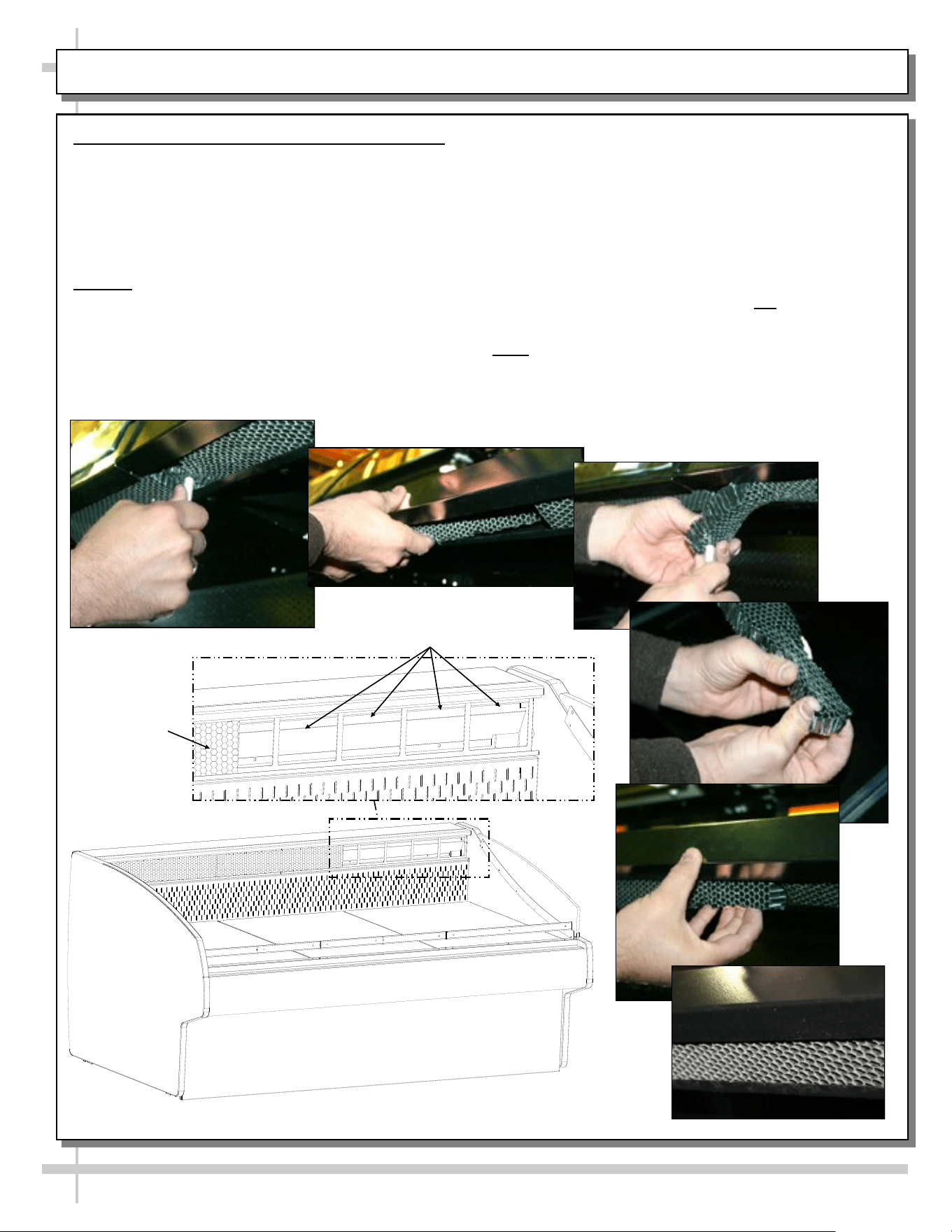
HONEYCOMB AIR DIFFUSERS (SERVICE TECHNICIANS ONLY) - PAGE 1 of 2
1. Flat Case Honeycomb Air Diffuser Removal
See PREVENTIVE MAINTENANCE (TO BE
PERFORMED BY TRAINED SERVICE PROVIDER)
section in this manual for cleaning frequency.
A. Wedge a non-metallic device of suitable strength
(such as a ballpoint pen) between the honeycomb
and the end panel.
Caution! Use care not to dislodge the heating wire
(that prevents condensation on the lamp assembly).
B. Apply pressure to collapse the honeycomb to
allow it to be pulled out of honeycomb retainer.
C. Carefully pry downward and away from the
honeycomb retainer.
A
B
C
D
E
F
Clean honeycomb with warm water and soap
solution. Submerse if necessary. Use brush to
dislodge stubborn or sticky residue. Dry by using
vacuum’s blow mode (vs. suction mode).
Honeycomb Air Diffuser Installation
D. Squeeze honeycomb to allow it to fit into the
honeycomb retainer.
E. Carefully slide honeycomb into place.
F. Adjust honeycomb so that it fits flat against
retainer. It must not be wavy or out of position.
Note: See next page for honeycomb air diffuser
information pertaining to oval cases.
Model GLDSS6R is Shown Above
Honeycomb
Air Diffuser Removed
Honeycomb
Intact
21
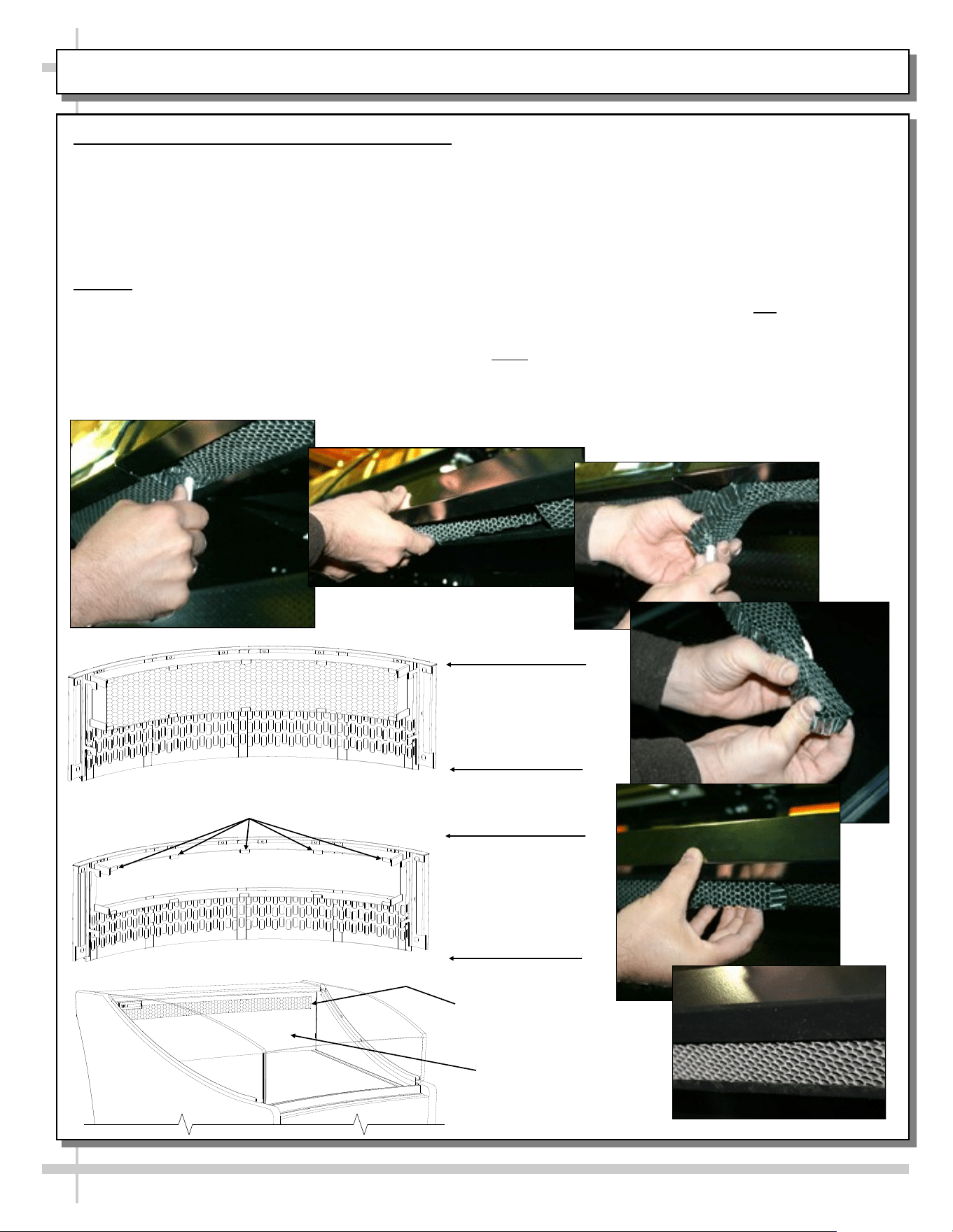
HONEYCOMB AIR DIFFUSERS (SERVICE TECHNICIANS ONLY) - PAGE 2 of 2
2. Oval Case Honeycomb Air Diffuser Removal
See PREVENTIVE MAINTENANCE (TO BE
PERFORMED BY TRAINED SERVICE PROVIDER)
section in this manual for cleaning frequency.
A. Wedge a non-metallic device of suitable strength
(such as a ballpoint pen) between the honeycomb
and the end panel.
Caution! Use care not to dislodge the heating wire
(that prevents condensation on the lamp assembly).
B. Apply pressure to collapse the honeycomb to
allow it to be pulled out of honeycomb retainer.
C. Carefully pry downward and away from the
honeycomb retainer.
A
B
C
D
E
F
Clean honeycomb with warm water and soap
solution. Submerse if necessary. Use brush to
dislodge stubborn or sticky residue. Dry by using
vacuum’s blow mode (vs. suction mode).
Honeycomb Air Diffuser Installation
D. Squeeze honeycomb to allow it to fit into the
honeycomb retainer.
E. Carefully slide honeycomb into place.
F. Adjust honeycomb so that it fits flat against
retainer. It must not be wavy or out of position.
Note: See previous page for honeycomb air diffuser
information pertaining to straight/flat cases.
Honeycomb Air Diffuser Retaining Clips
View of Panel
Back Assembly
with Honeycomb
Air Diffuser Intact
View of Panel Back
Assembly with
Honeycomb
Air Diffuser
Removed
Honeycomb
Air Diffuser
Panel Back
Assembly
22
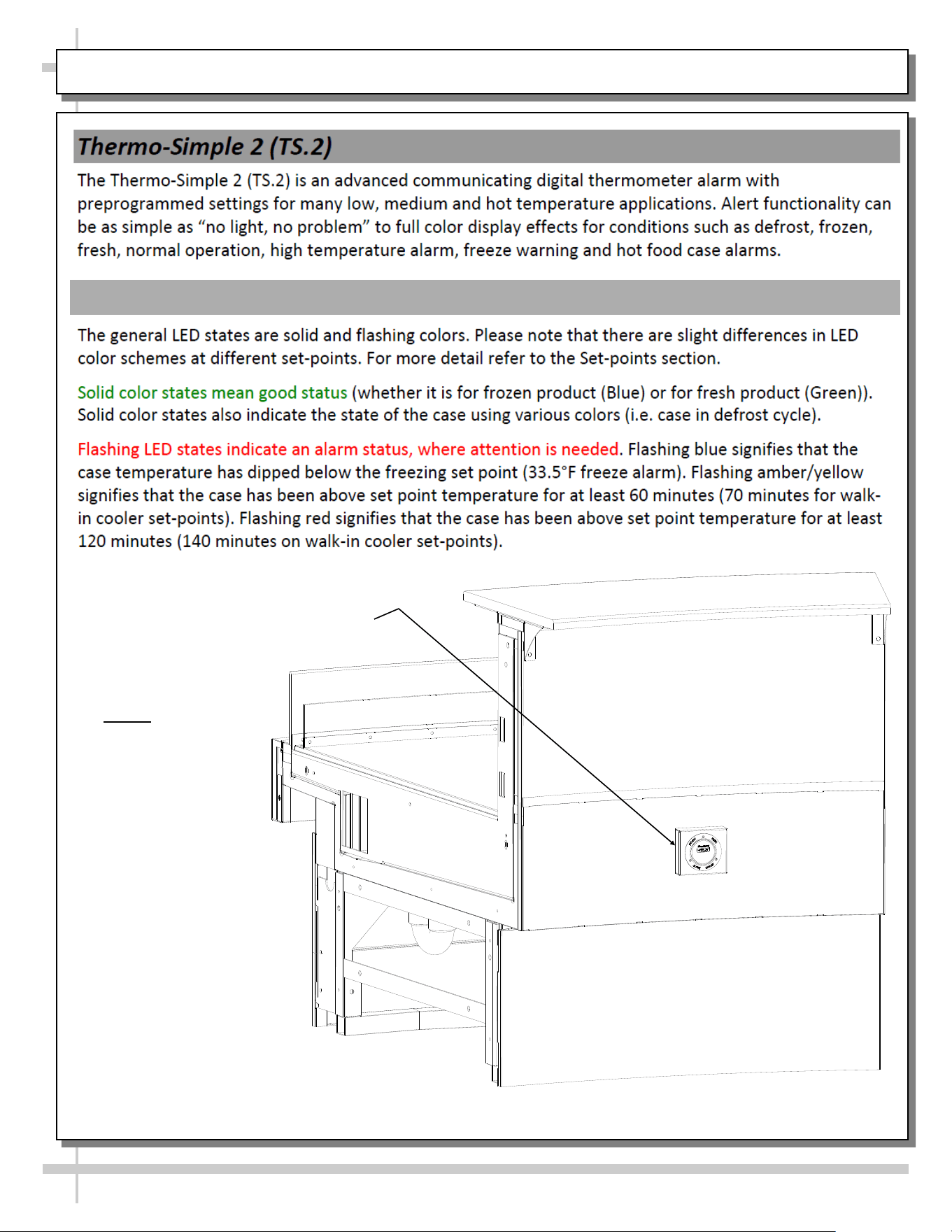
START-UP & OPERATION - THERMO-SIMPLE 2 (TS.2) DIGITAL THERMOMETER ALARM - PG #1 OF 2
Thermo-Simple 2 (TS.2) Digital
Thermometer Alarm
(Note: Alarm is Not on All Cases)
--- Model GLDSSX239R Case Rear Shown Above ---
Thermo-Simple 2 (TS.2) Colors Schemes / Flashing / Alarm Status
NOTE: THESE
TWO PAGES
PROVIDE A
GENERAL
OVERVIEW OF THE
Thermo-Simple 2
(TS.2) DIGITAL
THERMOMETER
ALARM.
SEE THE
Thermo-Simple 2
(TS.2) Manual
(SCC P/N 20-16086)
FOR MORE
SPECIFIC
INFORMATION.
23
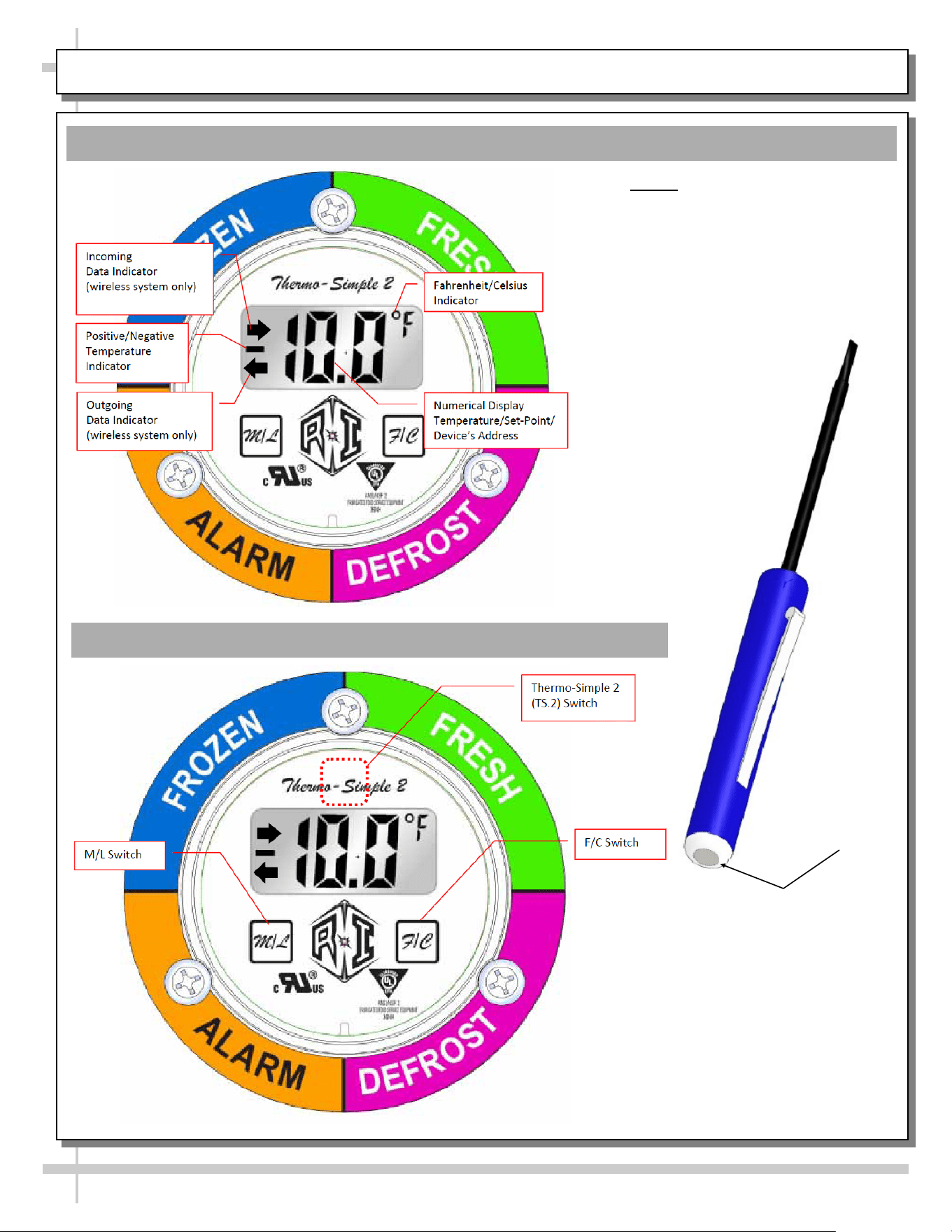
START-UP & OPERATION - THERMO-SIMPLE 2 (TS.2) DIGITAL THERMOMETER ALARM - PG #2 OF 2
Thermo-Simple 2 (TS.2) Display
Thermo-Simple 2 (TS.2) Magnetic Switches
To trigger a magnetic switch on the TS.2
device, a Refrigeration Innovation Magik
Wand is needed. The Magik Wand can be
purchased from Refrigeration Innovation,
LLC. The Magik Wand will ensure that the
switches are triggered properly.
In absence of a Magik Wand, the magnetic
switches on a TS.2 device can be triggered
by any strong magnet (Neodymium
rare-earth type). A typical refrigerator door
magnet or whiteboard magnet is not strong
enough.
Magik Wand
magnet end is
used to trigger
magnetic
switches.
NOTE: THESE TWO PAGES
PROVIDE A GENERAL OVERVIEW
OF THE Thermo-Simple 2 (TS.2)
DIGITAL THERMOMETER ALARM.
SEE THE Thermo-Simple 2 (TS.2)
Manual (SCC P/N 20-16086) FOR
MORE SPECIFIC INFORMATION.
24
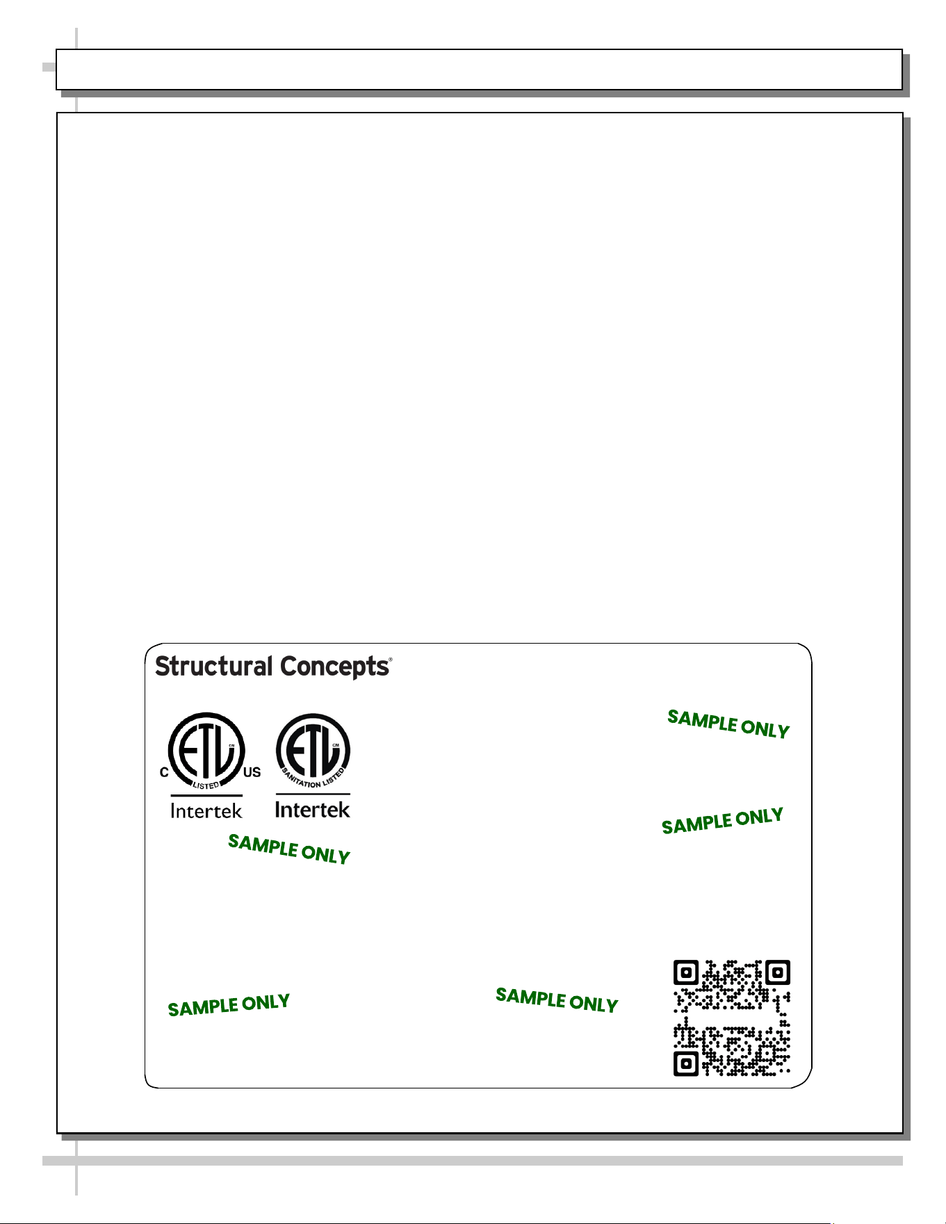
SERIAL LABEL LOCATION & INFO LISTED / TECH INFO & SERVICE / REFRIGERATED CASES ONLY
--- Sample Serial Label For Refrigerated Cases ---
MODEL NRS3648RXV-SAMPLE
SERIAL NO. 12345X30DZ098765
TYPE II DISPLAY REFRIGERATOR: THIS EQUIPMENT IS INTENDED FOR USE IN AN AREA
WHERE THE ENVIRONMENTAL CONDITIONS ARE CONTROLLED AND MAINTAINED SUCH
THAT THE AMBIENT TEMPERATURE DOES NOT EXCEED 80 °F (27 °C).
888 E. Porter Rd - Muskegon, MI 49441
3048256
Conforms to UL Std. 471
Conforms to NSF/ANSI Stds. 2 & 7
CERTIFIED TO CAN/CSA
STD C22.2 NO 120
ELECTRICAL RATING
REFRIGERANT
DESIGN PRESSURE
MINIMUM CIRCUIT AMPACITY
MAXIMUM OVERCURRENT
120/1/60 16 A
R513A AMOUNT 50 OZ
HIGH 186 LOW 88
20A
20A
Super Heat Temp 6-8 °F FOR PARTS AND SERVICE
Defrost 6 defrosts per day, 45 °F CALL 1-800-433-9490
Serial Label Location & Information Listed /
Technical Information & Service
• Serial labels are affixed at a wide range of places
(on the header, near thermostat, at case rear,
behind panels/toe-kicks, on electrical boxes, etc.).
• Serial labels contain electrical, temperature and
refrigeration information, as well as regulatory
standards to which the case conforms.
• Sample serial label shown below.
• For additional technical information and service, see
the TECHNICAL SERVICE page in this manual for
instructions on contacting Structural Concepts’
Technical Service Department.
Reveal
Harmony
Fusion
Impulse
Addenda
Blend
Grocerant
Oasis
Sample QR Code
SCAN FOR PRODUCT LITERATURE
25
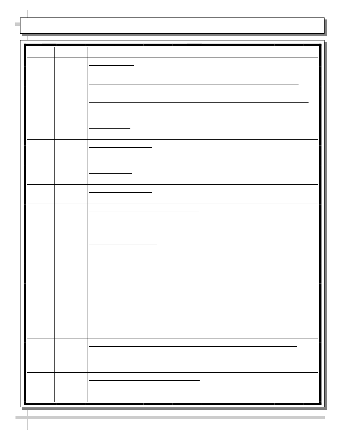
CLEANING SCHEDULE (TO BE PERFORMED BY STORE PERSONNEL)
AREA FREQ. INSTRUCTIONS
Exterior Daily Condenser Coil: Vacuum or brush condenser coil at case rear (after removing rear
grille).
Daily Top Board or Work Counter (Optional in Rear ‘Push-Up’ Work Counter): Clean
with a warm water and mild soap solution and soft cloth.
Daily End Glass / Glass Sneeze Guard on Rear ‘Push-Up’ Work Counter(Optional):
Clean with a household or commercial glass cleaner. Wipe dry with clean, dry
cloth or paper towel.
Daily Butcher Block: See BUTCHER BLOCK CLEANING INSTRUCTIONS (TO BE
PERFORMED BY STORE PERSONNEL) for cleaning specifics.
Daily Avonite Solid Surface: See AVONITE SURFACE CLEANING, CARE &
MAINTENANCE (TO BE PERFORMED BY STORE PERSONNEL) for cleaning
specifics.
Daily Stainless Steel: CLEANING SCHEDULE: STAINLESS STEEL (TO BE
PERFORMED BY STORE PERSONNEL) section in manual for specifics.
Weekly Acrylic Sneeze Guard: Clean with a warm water and mild soap solution and soft
cloth. Never use ammonia-based cleaners on acrylic.
Monthly Rear Sliding Doors (For Storage Area):
>> Door: Wipe down with warm water and mild soap solution and soft cloth.
>> Door Tracks: Use vacuum to remove dust, dirt and other residue that is in door
tracks. Then wipe down with warm water and mild soap solution and soft cloth.
Quarterly Adjustable Scale Stand: See ADJUSTABLE SCALE STAND section in manual.
• To clean butcher block, see next page.
• Remove adjustable scale stand by loosening thumbscrews, loosening all six (6)
retaining screws and lifting off merchandiser.
• Caution! Use only hand-held Phillips™ screw driver to loosen retaining
screws (at underside of adjustable scale stand). Do not use power driver!
• If unable to lift off merchandiser, it may be necessary to entirely remove inner
retaining screws.
• Submersed in warm, soapy water. Use nylon bristled brush and/or soft cloth to
remove residue.
• Rinse. Dry thoroughly before returning to merchandiser.
Interior Weekly Decks, Steps and Shelf Area (Optional in Rear ‘Push-Up’ Work Counter): Wipe
off components with moist cloth. For stubborn, hardened residue, remove from case
and submerse in warm, soapy water; use soft-bristled brush to remove residue.
Rinse. Dry with paper towel or clean cloth. Return to case.
Monthly Air Return Grille and Fan Shroud Area: 1) Turn off power. 2) Remove decks
from case. 3) Clean with moist cloth. See Maintenance Fundamentals that pertain
to Evaporator Fans, TXV and Drain Access for illustration.

26
AVONITE SURFACE CLEANING, CARE, MAINTENANCE (TO BE PERFORMED BY STORE PERSONNEL)
Avonite Solid Surfaces Cleaning, Care and Maintenance
Taking into account the fact that there are three types of Avonite countertops finishes, the care and
maintenance tips are different.
The Three Finishes are: Satin, Matte and High Gloss
You must determine, based upon appearance, your particular unit’s finish.
1. The Satin finish Avonite countertops should be cleaned with sponge, water and soap. For special
stains you may use a non-abrasive cleanser and a white pad. In order to remove scratches, you
should use 400 grit paper and then 600 grit paper. The area should be cleaned then with the white
pad and the mentioned cleanser.
2. The Matte finish Avonite countertops should be cleaned with sponge, water and soap. Sanding
with 240 grit paper and cleaning with a green pad and abrasive cleanser may help in removing
scratches. Clean the entire matte surface form time to time in order to obtain the initial finish.
3. The High Gloss finish Avonite countertops should be cleaned with sponge, water and soap. For
the persistent stains, you should use polishing compound and soft cloth. Sanding with 400 grit paper
is helpful in the process of removing scratches. This type of surface may need machine polish and
you need to contact the producer, in order to have the original finish of the Avonite countertop.
Additional Maintenance Guidance:
It is highly recommended not to stand on the Avonite countertops and to avoid sliding hard objects
across these surfaces. Paint removers and other harsh chemicals should be avoided even if you
have stubborn stains.
There are special methods of cleaning these stains and none of them include harsh chemicals. You
should use cutting boards and special hot pads as part of your daily routine. Protectors should be
used especially in the case of High Gloss finish, in the case of hard objects and pottery.
27
CLEANING SCHEDULE: STAINLESS STEEL (TO BE PERFORMED BY STORE PERSONNEL)
General Stainless Steel Surface Cleaning (To Be Performed As Often As Needed):
• Certain grades of stainless steel, and some are more prone to corrosion than others.
• Stainless steel can become exposed to a wide variety of contaminants, which if left untreated can cause
stains and rust.
• Stainless steel requires a specific cleaning procedure to maintain its sheen and remain rust-free.
• Wash with a solution of liquid dishwashing detergent and hot water.
• Rinse with pure hot water from spray bottle. Wipe with clean sponge. This will remove soap residue
that can lodge in stainless steel’s microscopic grooves, causing rust.
• Dry with clean, soft cloth or paper towel.
• Caution! To prevent rust, you MUST rinse with pure hot water from a spray bottle while wiping with
clean sponge after EACH cleaning.
• Caution! Never clean with scouring powder or steel wool as they can mar, scratch and/or erode the
surface of stainless steel. When the surface properties of stainless steel have been compromised, rust
can form.
Brightening:
• Method 1: Brighten by polishing with a soft cloth or sponge with a solution of one part vinegar to 2 parts
water in a spray bottle.
• Method 2: Sprinkle baking soda on sponge and rub gently with soft cloth or sponge.
• Caution! To prevent rust, you MUST rinse with pure hot water from a spray bottle while wiping with
clean sponge after EACH cleaning.
• Dry with clean, soft cloth or paper towel.
Removing Streaks or Stains:
• Method 1: Place two teaspoons of rubbing alcohol on a microfiber cloth or pad. Rub the cloth along the
grain of the appliance until the entire area has been wiped. The rubbing alcohol will air dry itself.
• Method 2: Dip soft cloth or sponge in club soda and rub gently over area of concern.
• Caution! To prevent rust, you MUST rinse with pure hot water from a spray bottle while wiping with
clean sponge after EACH cleaning.
• Dry with clean, soft cloth or paper towel.
Polishing:
• Place a dab of olive oil onto clean soft cloth. Spread over area until a light sheen is observed. Use
pressure to “work the oil” into the small grooves in the surface. Apply firm, steady pressure using small
circular motions.
> Dry buff: Remove excess oil with clean cloth or paper towel using small circular motions.
> Wet buff: Use an ounce or white vinegar with clean cloth or paper towel using small circular motions.
> Continue wiping until oily finish has been removed.
• Caution! To prevent rust, you MUST rinse with pure hot water from a spray bottle while wiping with
clean sponge after EACH cleaning.
• Dry with clean, soft cloth or paper towel.
Removing Rust:
• If rust has begun to form, there are a variety of products that can treat it.
• Among these are CLR® (calcium, lime and rust remover) and Chemetall Oakite 33 (rust, oxides and
scale remover).
• Caution! To prevent food contamination, personal injury or further corrosion, carefully observe
and follow the rust removing product’s precautions and instructions.
I:\Oper Manuals\Specialty\Butcher Block Cleaning 20-02296.pub
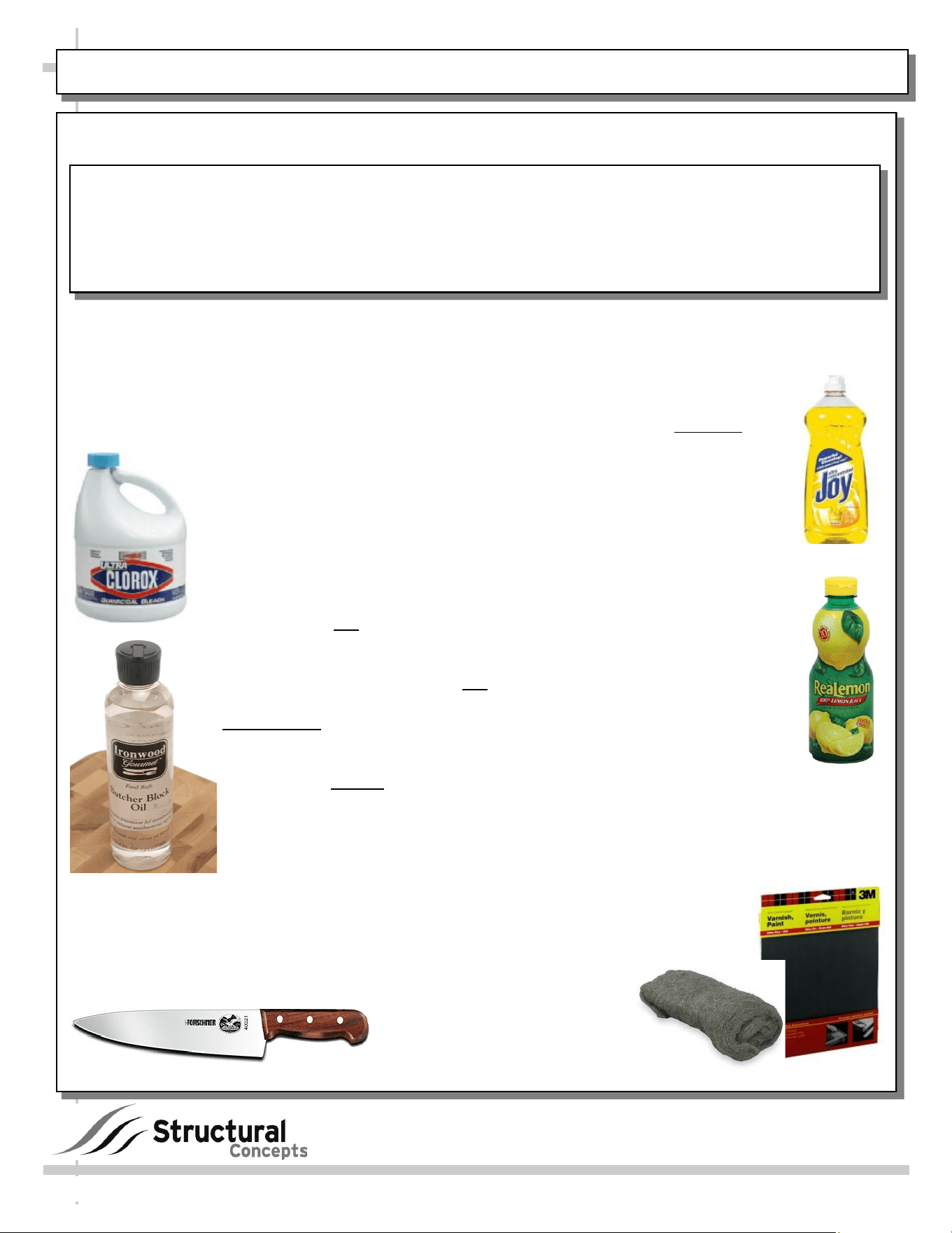
1. Dishwashing Liquid
2. Clean Sponge / Cotton Cloth / Paper Towel
3. Non-Toxic Wood Oil or Cream
888 E. Porter Road ∙ Muskegon, MI 49441 Phone: 231.798.8888 Fax: 231.798.4960 www.structuralconcepts.com
--- Recommended Cleaning Supplies ---
4. Bleach (Optional)
5. Lemon Juice (Optional)
6. Steel Wool or Sandpaper (Optional)
Please Follow These Instructions To Properly Clean
and Care for Your Butcher Block Surface
1. Wash the countertop with mild soap and water. Regular liquid dish washing
detergent works well. As little as 2 to 3 drops of liquid dish soap to a quart of warm
water is sufficient. Use a clean sponge or dish towel to clean surface. Caution!
Never use an abrasive cleaning solution on ANY wood countertop!
2. Kill bacteria (often left behind by raw meat), with bleach. Add one
tablespoon of bleach into one gallon of warm water. Do not use a
higher concentration of bleach or wood will crack. Immediately rinse the
countertop with this solution to kill any bacteria. This will help prevent
food borne illnesses.
3. Remove tough stains from butcher block by pouring lemon juice on
the surface and letting it soak for several seconds.
4. Dry the butcher block surface with a soft cloth immediately after
cleaning. Do not allow standing water or moist surfaces to remain on
the butcher block. Also, use the soft cloth to dry moist or wet crevices
so that no moisture remains.
5. Varnished countertops do not need oil treatments. Just follow
steps 1 through 4 above for varnished countertops. Maintain
unvarnished surfaces with a non-toxic oil or warm mineral oil
treatments on a weekly basis or whenever you notice the wood drying
or color fading. Ironwood® Gourmet Butcher Block Oil (shown at left)
is food safe. Do not use vegetable oil or sunflower seed oil as the oil
will become rancid and leave odor. Apply mineral oil to the butcher block surface
in thin coats. Allow the oil to permeate the surface for as little as 5 minutes and
as long as six (6) hours. Blot excess oil off the countertop with a soft cloth. Wipe
away the remainder with a paper towel or cotton cloth. Wait 12 hours before
using the counter.
6. Stains on butcher block can be removed with steel wool or sandpaper. Rub on
the surface until stains disappear. Then, coat the surface with mineral oil (see
#5 for instructions).
7. Always use a plastic or metal cutting board on a wood surface
when cutting. Cutting directly
on the butcher block will leave
behind knife marks that will be
difficult to clean or repair.
28
BUTCHER BLOCK CLEANING INSTRUCTIONS (TO BE PERFORMED BY STORE PERSONNEL)
Butcher Block Cleaning Instructions
CaesarStone® Care & Maintenance
TAKING CARE OF YOUR QUARTZ SURFACE
CaesarStone quartz surfaces blend modern sophistication
and timeless luxury with unbeatable strength and
durability. The ever-lasting finish requires only simple and routine care to maintain its good looks.
MINIMAL MAINTENANCE
Virtually maintenance-free, CaesarStone’s hard, non-porous surfaces require no sealing to renew the
luster and are simple to clean. In most cases, dip a clean, soft cloth into a solution of water and soap
(or mild detergent) solution and wipe away dust, smudges and residue; then rinse with clean water to
remove residue. This simple treatment is usually enough to keep your CaesarStone countertop
looking like new. If necessary, use a non-abrasive soft soap along with a non-scratch or delicate
scrub pad. Afterwards, thoroughly rinse with clean water to remove residue.
STUBBORN STAINS OR DRIED SPILLS
If needed, apply a non-abrasive household cleaners (a non-abrasive cleaner will not dull the surface
shine); rinse to remove residue. To remove adhered material such as food, gum, nail polish or even
dried paint, first scrape away excess material with a plastic putty knife and then use a damp cloth to
remove any marks or residual dirt. For extra-stubborn stains, use a no-scratch Scotch-Brite® pad
along with the non-abrasive cleaner recommended by your local CaesarStone® distributor.
HEAT TOLERANCE
CaesarStone is more heat resistant than other stone surfaces including most granite, marble and
limestone; it is not affected by temperatures lower than 300 °F (149 °C). However, like all stone
material, CaesarStone can be damaged by sudden and rapid temperature changes. Therefore, do not
place hot pots or pans directly placed on the surface. Instead place a hot pad or trivet on the surface
under cooking units such as electric frying pans, crock pots, or roaster ovens.
SCRATCH RESISTANT
CaesarStone is a highly scratch resistant surface; however avoid abuse of the surface by refraining
from using sharp objects such as sharp knives or screw drivers directly onto the surface.
CLEANING AGENTS TO AVOID
• It’s important to be aware that like any other surface, CaesarStone can be permanently damaged
if exposed to strong chemicals and solvents that can damage its physical properties.
• Never clean your CaesarStone surface with products that contain Trichlorethane or Methylene
chloride, such as paint removers or strippers.
• Avoid the use of highly aggressive cleaning agents such as oven/grill cleaners and dishwasher
polishing agents that have high alkaline/pH levels (pH 8.5 or higher).
• Products containing oils or powders may leave a residue and should be rinsed off thoroughly.
Should your surface accidentally be exposed to any of these damaging products, rinse
immediately with clean water to neutralize the effect.
CAESARSTONE® SOLID SURFACE CARE & MAINTENANCE (PERFORMED BY STORE PERSONNEL)
29
30
PREVENTIVE MAINTENANCE (TO BE PERFORMED BY TRAINED SERVICE PROVIDER) - Page 1 of 2
PREVENTIVE
MAINTENANCE
FREQUENCY INSTRUCTIONS
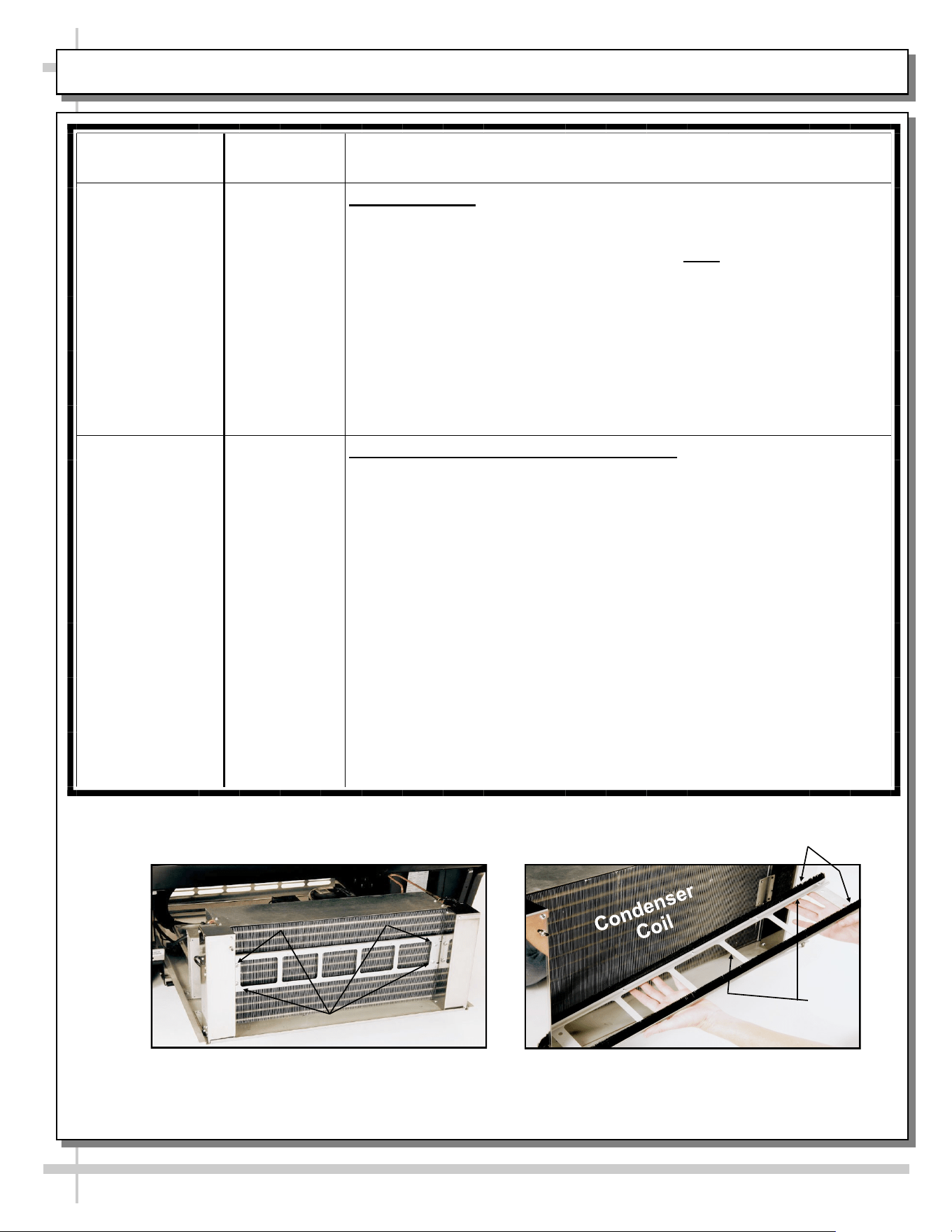
Case Exterior Monthly Condenser Coil: Disconnect power from case before cleaning the
Condenser Coil!
• Remove Rear Grille (by removing 4 screws).
• Roll / Slide out Refrigeration Assembly. Note: At initial slide-out, it
may be necessary to remove two (2) Compressor Pan Shipment
Screws for Refrigeration Assembly to slide out.
• Use air pressure or industrial strength vacuum; clean dust and dirt
that may collect on the Condenser Coil. See illustration below.
• Caution! Coil fins are sharp. Handle with care!
• Slide/Roll Condenser Unit Assembly back under case.
• Replace Rear Grille to case (4 screws).
• See illustration below.
Quarterly Optional Clean Sweep™ Condenser Coil: Disconnect power from
case before cleaning Clean Sweep™ Condenser Coil!
• Remove Rear Grille (by removing 4 screws).
• Slide/Roll out condensing unit assembly.
• Remove the four (4) screws holding the Clean Sweep™ rails intact.
• Remove the Clean Sweep™ rail.
• Wash rails’ brushes in hot water and mild soap solution.
• If brushes are worn, they must be replaced. Call Technical Service
Department to replace. Toll-Free number is listed at end of
manual.
• Clean Condenser Coil: Use air pressure or industrial strength
vacuum; clean the dust and dirt that may collect on the Condenser
Coil.
• Caution! Coil fins are sharp. Handle with care!
• Reattach Clean Sweep rail to condensing unit (4 screws).
• Slide/Roll Condensing Unit Assembly back under case.
• Replace Rear Grille to case (4 screws).
• See photos below.
(4) Screws
--- Above photos are taken after rear grille has been removed from case ---
Brushes
Rail
31
PREVENTIVE MAINTENANCE (TO BE PERFORMED BY TRAINED SERVICE PROVIDER) - Page 2 of 2
PREVENTIVE
MAINTENANCE
FREQUENCY INSTRUCTIONS
Case Exterior Quarterly Compressor Area: Warning! Disconnect power from the case before
cleaning Condenser Coil!
• Slide/Roll out from under case.
• Use moist cloth to wipe off dust & debris that collects on various
parts.
Quarterly Condensate Pan: Disconnect from receptacle box. Remove mounting
screws from base. Use a de-scaling solution (such as CLR® that will
prevent corrosion, lime and rust) to clean pan. Rinse thoroughly; do
not submerse in water.
Quarterly Under Case Cleaning: Once refrigeration package is clear of unit,
vacuum under case to remove all dust and dirt that may collect under
case.
Case Interior Quarterly Tub, Coil and Drain: Remove Evaporator Fan Panel and clean Tub,
Coil and Drain with warm water and mild soap solution. Remove any
debris that may clog drain.
Quarterly Fan Blades, Motor, and Bracket: Wipe down each blade, motor and
bracket with moist cloth.
Quarterly Honeycomb: Remove the honeycomb. Vacuum, then clean with
warm water and soap. See specific instructions in the Maintenance
Fundamentals section of this manual.
32
CONDITION TROUBLESHOOTING
Case Not Lining
Up
See Installation Section for instructions on properly aligning case (alongside other
cases) and adjusting levelers.
Water Is On The
Floor
Caution! Water on flooring can cause much damage! Until cause is determined
(and repaired), follow these procedures:
• Use wet-dry vacuum (or mop & bucket) to remove standing water.
• Use ‘catch pans’ for water to drain into. Swap out regularly until case has
completely drained.
Check that the drain trap is free of debris.
Check that the drain hose is correctly positioned over condensate pan (or floor drain,
for remote units).
Check store conditions. To prevent condensation in Type 1 condition environments,
maximum conditions are to be 55% humidity / 75 °Fahrenheit. For Type 2 condition
environments, maximum conditions are to be 60% humidity / 80 °Fahrenheit. See
serial label (at case rear near main power switch) for Type of your case.
Check condensate pan float for proper operation (heat rod condensate system only).
Check that condensate pan is properly plugged in or connected.
Caution! Condensate pan may be malfunctioning (electrical heat rod condensate
system). If so, water will overflow pan and seep onto flooring causing damage! Until
condensate pan is functioning (or is replaced), follow these procedures:
• Use wet-dry vacuum (or mop & bucket) to remove standing water.
• Use ‘catch pans’ for water to drain into. Swap out regularly until case has
completely drained.
Caution! Disruption of power can cause water to overflow pan and seep onto
flooring causing damage! Check that power to case is constant. Until power is
restored, follow these procedures:
• Use wet-dry vacuum (or mop & bucket) to remove standing water.
• Use ‘catch pans’ for water to drainage. Swap out regularly until evaporation of
case is complete (or until power is restored).
• When power to case is restored, condensate pan should function properly and
water will no longer overflow onto flooring.
Caution! Wicking material may be dirty or worn and need replacement (hot gas
condensate system only).
• Slide refrigeration system out from under unit.
• After refrigeration system has been carefully slid out from under unit, replace
wicking material with new. If wicking material is not available, contact Structural
Concepts®. See toll-free number at last page of this operating manual.
TROUBLESHOOTING (TO BE PERFORMED BY TRAINED SERVICE PROVIDERS ONLY) - PAGE 1 of 3
33
CONDITION TROUBLESHOOTING
Fan Emits Excessive
Noise
Check that the case is aligned, level and plumb.
Check evaporator fan for cleanliness.
Unplug/power off fan motors. Check motor shaft for bearing wear.
Check that fan motors are securely mounted in brackets.
Verify that fan blades are securely mounted to fan motor.
Check that nothing is preventing blade rotation.
Check that the fan shroud is properly secured.
Fans Are Not Working Check that the MAIN power switch is on.
Check that fans are plugged in at the fan shroud.
Check for foreign material obstructing fan performance.
Check that fan blades freely rotate within fan shrouds
Check that power is going to fans
Check that fan wiring is connected on terminal blocks.
Digital Control Display
Is Blank
Check that the MAIN power switch is on.
Check the circuit breaker box for tripped circuits.
System Not Operating Check that the utility power is on.
Check that the MAIN power switch is on.
Check the circuit breaker box for tripped circuits.
TROUBLESHOOTING (TO BE PERFORMED BY TRAINED SERVICE PROVIDERS ONLY) - PAGE 2 of 3
34
CONDITION TROUBLESHOOTING
Control Display Is
Flashing
See your case’s serial label for your model’s specified settings. See SERIAL
LABEL LOCATION & INFORMATION LISTED / TECH INFO & SERVICE for label
location, etc.
See the Carel® Controller thermostat sheets in this manual for codes that may be
displayed on controller identifying problem.
Case Is Not Holding
Temperature
If a large amount of warm product was added to the case, it will take time for the
temperature to adjust. Unit needs product to be pre-chilled.
Temperature changes during defrost mode but will return to normal. Fourth LED
will indicate defrost cycle in progress.
Check that case is not in sun or near a heat or air-conditioning vent. See
OVERVIEW / TYPE / COMPLIANCE / WARNINGS / PRECAUTIONS / CORDS /
WIRING section in manual for adverse conditions/spacing issue parameters.
If case is located near front doors, temperature fluctuation can hinder unit’s ability
to maintain temperature. See OVERVIEW / TYPE / COMPLIANCE / WARNINGS /
PRECAUTIONS / CORDS / WIRING section in manual for adverse conditions/
spacing issue parameters.
Check that condenser coil air filter (attached to rear grille) has been cleaned. See
GENERAL CLEANING (TO BE PERFORMED BY STORE PERSONNEL) section
in operating manual for instructions.
Check that condenser coil has been cleaned.
Check air return grilles for obstructions.
Check sight glass for flashing and/or low charge.
Check Set Point Temperature; it may be adjusted too high.
Condensing Unit Is
Not Operating
Check that the power is turned on.
Determine if temperature controller settings are properly set. See your case’s
serial label for your model’s specified settings. See SERIAL LABEL LOCATION &
INFORMATION LISTED / TECH INFO & SERVICE section in manual for label lo-
cation, etc.
TROUBLESHOOTING (TO BE PERFORMED BY TRAINED SERVICE PROVIDERS ONLY) - PAGE 3 of 3
35
TROUBLESHOOTING - CONDENSING SYSTEM (BY TRAINED SERVICE PROVIDERS ONLY)
CONDITION TROUBLESHOOTING
Head Pressure Too High Check that the condensing coil is not dirty or covered.
Check that condensing fans are working.
Check that refrigerant is not overcharged.
Perform sub-cooling check and verify that no contaminates are in system.
Check that liquid line filter dryer is not plugged.
Check that close-offs are intact (around condensing coil) and that air is not
recirculating.
Check that store ambient temperature isn’t above maximum allowed. See
OVERVIEW / TYPE / COMPLIANCE / WARNINGS / PRECAUTIONS /
WIRING / PLUGS section in this manual.
Head Pressure Too Low Check if sight glass is flashing or showing low charge.
Check that suction pressure isn’t too low.
Check that compressor reed valves aren’t bad. Look for high suction/low
head pressure. Perform pump-down.
36
TROUBLESHOOTING (BY TRAINED SERVICE PROVIDERS ONLY) - EVAPORATOR SYSTEM
CONDITION TROUBLESHOOTING
Low Suction Pressure Check if sight glass is flashing or showing low charge.
Check that expansion valve (TXV) isn’t restricted. Check element charge.
Check that liquid line or filter isn’t restricted. Check that refrigeration lines
and/or hoses are not kinked on either high or low sides.
Check that evaporator fan motors are working.
Check that superheat is between 6 °F to 8 °F.
Check that there is no air recirculation around evaporator coil.
Check that evaporator coil is not iced up.
High Suction Pressure Check for refrigerant overcharge.
Check that compressor reed valves aren’t bad. Look for high suction/low
head pressure. Perform pump down.
Check that the “cooling load” isn’t high. Product must be pre-chilled before
placing in refrigerated section of case.
Check that case is at least 15-feet from exterior doors, overhead HVAC
vents or any air curtain disruption.
Check that unit is not exposed to direct sunlight via windows or any other
heat source (ovens, fryers, etc.).
Check that superheat adjustment isn’t low.
Check TXV bulb installation
a. Poor thermal contact.
b. Warm location.
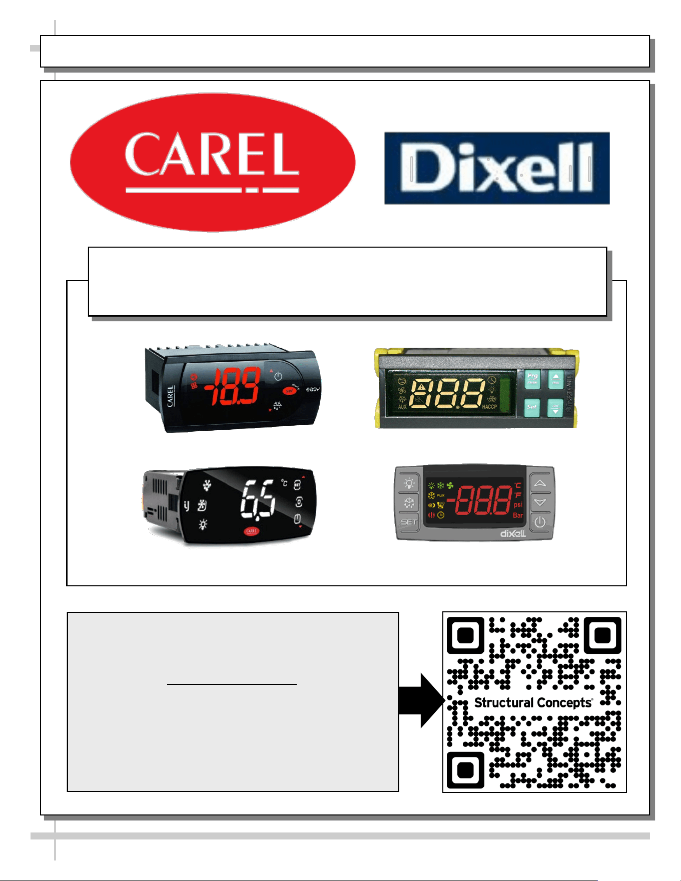
PROGRAMMABLE CONTROLLER (SELECT, CLICK ON OR SCAN QR CODE FOR INFORMATION)
37
Carel® iJF Platform
Carel® PJEZ Platform
Carel® ir33 Platform
Dixell® XM670K-XM679K Platform
To Access Information About The Programmable
Controller That Is Used On Your Case,
Follow These Instructions:
> If Viewing This Document on Smart Phone, Tablet
or Computer, Select/Click On The QR Code at Right.
> If Viewing This Document In Print (Hard Copy),
Scan The QR Code at Right With Your Smart Phone
or Tablet.
Determine Which Programmable Controller Is On Your Case (Controllers
That Are Commonly Used By Structural Concepts Are Shown Below).
Your Particular Programmable Controller May Differ.
STRUCTURAL CONCEPTS TECHNICAL SERVICE CONTACT INFORMATION & LIMITED WARRANTY
38
TECH SERVICE/WARRANTY CONTACT INFO:
1 (800) 433-9490 / EXTENSION 1
DAYS/HOURS AVAILABLE:
MONDAY - FRIDAY (CLOSED HOLIDAYS)
8:00 a.m. TO 5:00 p.m. EST
YOU MUST HAVE THE FOLLOWING INFO AVAILABLE
BEFORE CONTACTING STRUCTURAL CONCEPTS:
SERIAL NO. / MODEL NO. / STORE NO. / STORE
ADDRESS / DETAILS (PHOTOS, LEAK LOCATIONS,
DAMAGE, STORE’S AMBIENT CONDITIONS, ETC.)
To Access The Limited Warranty To Your
Case, Follow These Instructions:
> If Viewing This Document on Smart Phone,
Tablet or Computer, Select/Click On The QR
Code at Right.
> If Viewing This Document In Print (Hard
Copy), Scan The QR Code at Right With Your
Smart Phone or Tablet.