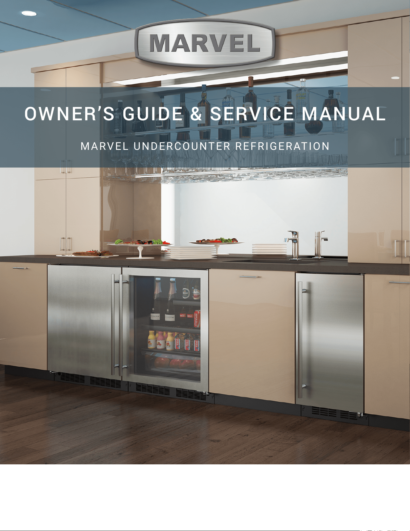
OWNER’S GUIDE & SERVICE MANUAL
MARVEL UNDERCOUNTER REFRIGERATION
Model: MANP415-SS01A
WELCOME
Welcome to the Marvel Experience!
Thank you for choosing our quality product to add to your
home. We are thrilled to welcome you to our growing
community of Marvel owners, who trust in our products and
our support.
The information in this guide is intended to help you install
and maintain your new Marvel undercounter model to
protect and prolong its lifetime. We encourage you to
contact our Technical Support team at (616) 754-5601 with
any questions.
Got a Marvelous Design?
We would love to see how your Marvel product looks in its
new home. You can send us photos of your installed
product at [email protected], and we
might feature your Marvel home design on our website and
social media!
Warranty Registration
It is important you register your product warranty after
taking delivery of your appliance. You can register online at
www.marvelrefrigeration.com.
The following information will be
required when registering your
appliance:
Serial Number
Date of Purchase
Dealer’s Name and Address
The serial number is located on the back of the cabinet
near the top.
Online registration
available at
marvelrefrigeration.com
TABLE OF CONTENTS
Tip: Click on any section below to jum
p directly there
Safety
Important Safety Instructions
Installation
Unpacking Your Appliance
Electrical
Cutout & Product Dimensions
Installing Your Appliance
Door Reversal
Installing The Water Supply
Installing the Drain plumbing
Maintenance
Care and Cleaning
Operating Instructions
Using Your Electronic Control
Ice Maker Operation
Service
Obtaining Service
Troubleshooting
Wire Diagram
Product Liability
Parts List
Ordering Replacement Parts
R600a Specifications
Compressor Specifications
Warranty
3
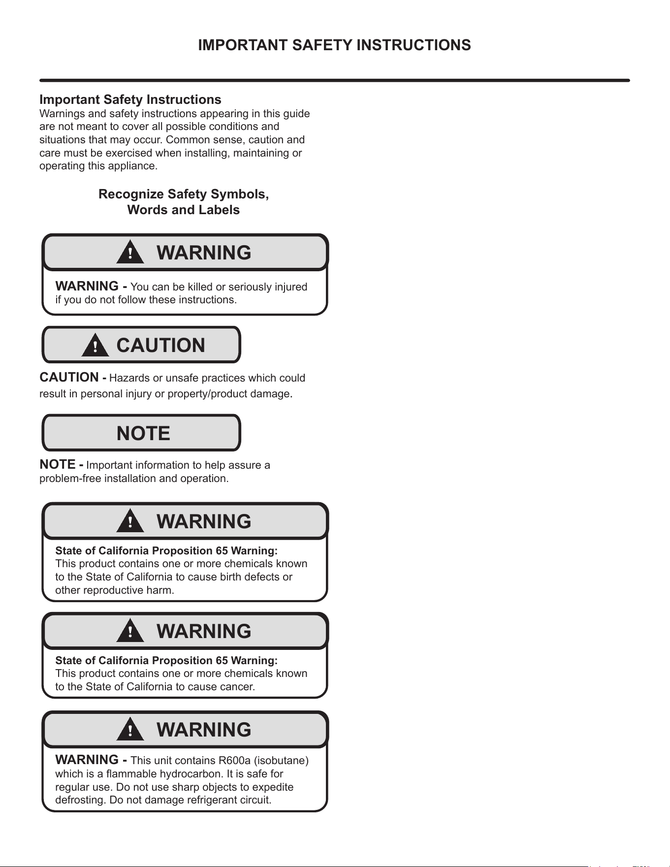
IMPORTANT SAFETY INSTRUCTIONS
Important Safety Instructions
Warnings and safety instructions appearing in this guide
are not meant to cover all possible conditions and
situations that may occur. Common sense, caution and
care must be exercised when installing, maintaining or
operating this appliance.
Recognize Safety Symbols,
Words and Labels
!
WARNING
WARNING - You can be killed or seriously injured
if you do not follow these instructions.
!
CAUTION
CAUTION - Hazards or unsafe practices which could
result in personal injury or property/product damage.
NOTE
NOTE - Important information to help assure a
problem-free installation and operation.
!
WARNING
State of California Proposition 65 Warning:
This product contains one or more chemicals known
to the State of California to cause birth defects or
other reproductive harm.
!
WARNING
State of California Proposition 65 Warning:
This product contains one or more chemicals known
to the State of California to cause cancer.
!
WARNING
WARNING - This unit contains R600a (isobutane)
which is a ammable hydrocarbon. It is safe for
regular use. Do not use sharp objects to expedite
defrosting. Do not damage refrigerant circuit.
4
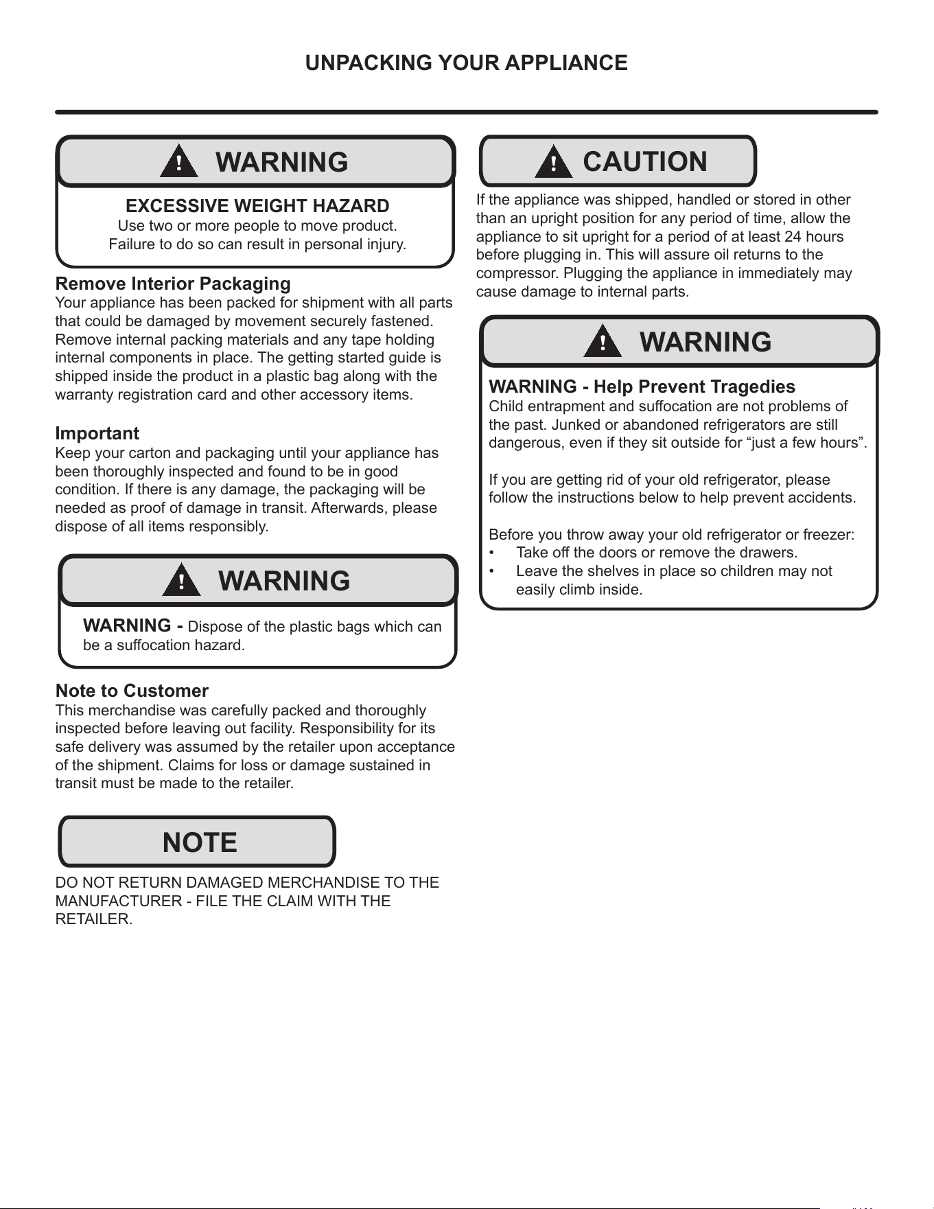
UNPACKING YOUR APPLIANCE
!
WARNING
EXCESSIVE WEIGHT HAZARD
Use two or more people to move product.
Failure to do so can result in personal injury.
Remove Interior Packaging
Your appliance has been packed for shipment with all parts
that could be damaged by movement securely fastened.
Remove internal packing materials and any tape holding
internal components in place. The getting started guide is
shipped inside the product in a plastic bag along with the
warranty registration card and other accessory items.
Important
Keep your carton and packaging until your appliance has
been thoroughly inspected and found to be in good
condition. If there is any damage, the packaging will be
needed as proof of damage in transit. Afterwards, please
dispose of all items responsibly.
!
WARNING
WARNING - Dispose of the plastic bags which can
be a suocation hazard.
Note to Customer
This merchandise was carefully packed and thoroughly
inspected before leaving out facility. Responsibility for its
safe delivery was assumed by the retailer upon acceptance
of the shipment. Claims for loss or damage sustained in
transit must be made to the retailer.
DO NOT RETURN DAMAGED MERCHANDISE TO THE
MANUFACTURER - FILE THE CLAIM WITH THE
RETAILER.
NOTE
!
CAUTION
If the appliance was shipped, handled or stored in other
than an upright position for any period of time, allow the
appliance to sit upright for a period of at least 24 hours
before plugging in. This will assure oil returns to the
compressor. Plugging the appliance in immediately may
cause damage to internal parts.
!
WARNING
WARNING - Help Prevent Tragedies
Child entrapment and suocation are not problems of
the past. Junked or abandoned refrigerators are still
dangerous, even if they sit outside for “just a few hours”.
If you are getting rid of your old refrigerator, please
follow the instructions below to help prevent accidents.
Before you throw away your old refrigerator or freezer:
• Take o the doors or remove the drawers.
• Leave the shelves in place so children may not
easily climb inside.
5
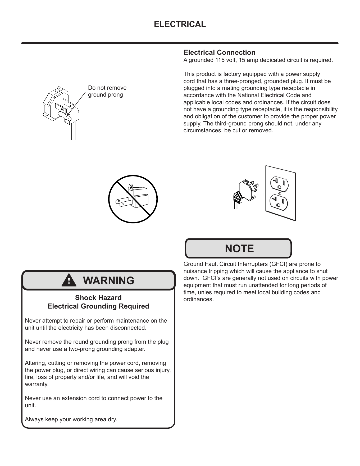
ELECTRICAL
Do not remove
ground prong
!
WARNING
Shock Hazard
Electrical Grounding Required
Never attempt to repair or perform maintenance on the
unit until the electricity has been disconnected.
Never remove the round grounding prong from the plug
and never use a two-prong grounding adapter.
Altering, cutting or removing the power cord, removing
the power plug, or direct wiring can cause serious injury,
re, loss of property and/or life, and will void the
warranty.
Never use an extension cord to connect power to the
unit.
Always keep your working area dry.
Electrical Connection
A grounded 115 volt, 15 amp dedicated circuit is required.
This product is factory equipped with a power supply
cord that has a three-pronged, grounded plug. It must be
plugged into a mating grounding type receptacle in
accordance with the National Electrical Code and
applicable local codes and ordinances. If the circuit does
not have a grounding type receptacle, it is the responsibility
and obligation of the customer to provide the proper power
supply. The third-ground prong should not, under any
circumstances, be cut or removed.
NOTE
Ground Fault Circuit Interrupters (GFCI) are prone to
nuisance tripping which will cause the appliance to shut
down. GFCI’s are generally not used on circuits with power
equipment that must run unattended for long periods of
time, unles required to meet local building codes and
ordinances.
6
CUTOUT & PRODUCT DIMENSIONS
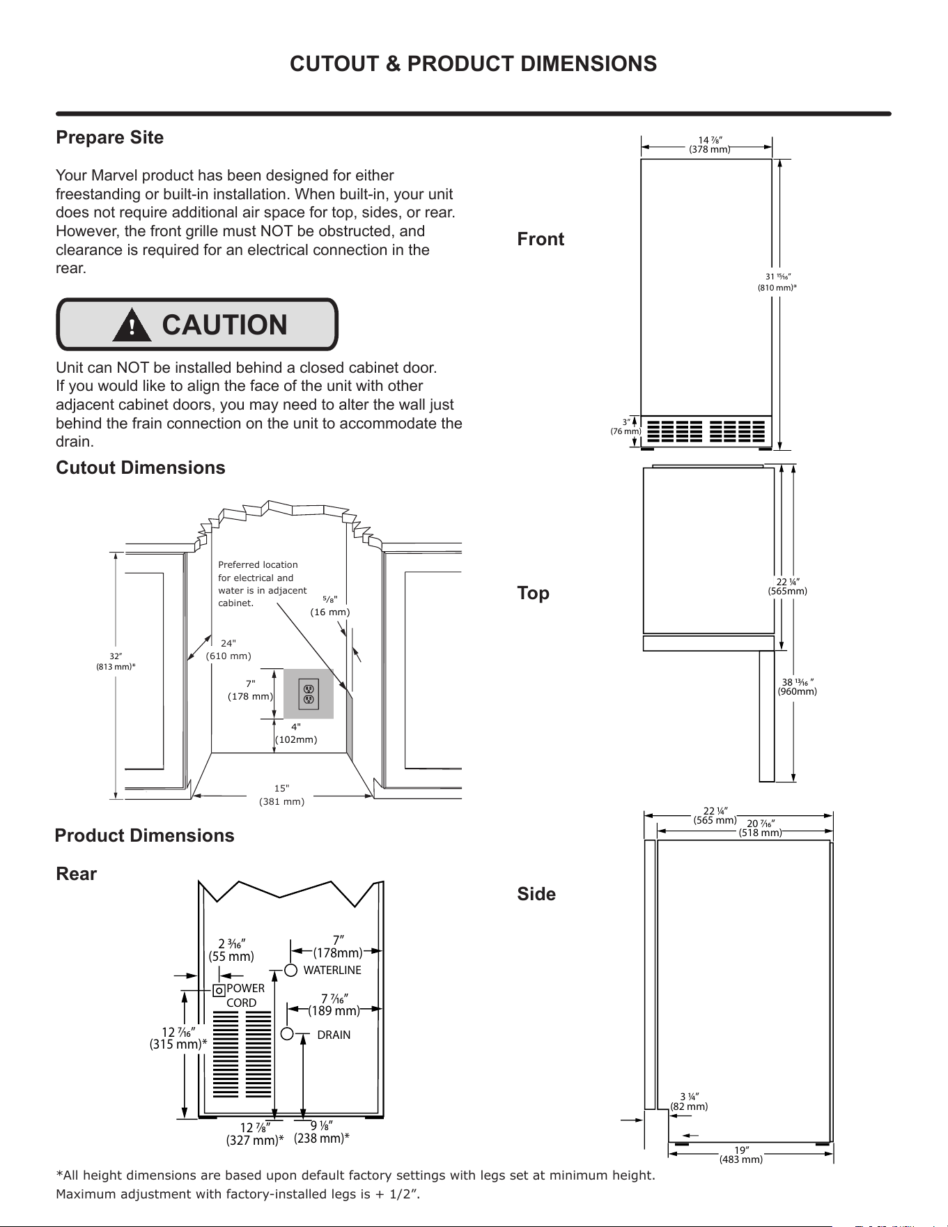
Prepare Site
Your Marvel product has been designed for either
freestanding or built-in installation. When built-in, your unit
does not require additional air space for top, sides, or rear.
However, the front grille must NOT be obstructed, and
clearance is required for an electrical connection in the
rear.
!
CAUTION
Unit can NOT be installed behind a closed cabinet door.
If you would like to align the face of the unit with other
adjacent cabinet doors, you may need to alter the wall just
behind the frain connection on the unit to accommodate the
drain.
Cutout Dimensions
Product Dimensions
Rear
Front
Top
Side
*All height dimensions are based upon default factory settings with legs set at minimum height.
Maximum adjustment with factory-installed legs is + 1/2”.
14 7⁄8”
(378 mm)
31 15⁄16”
(810 mm)*
3”
(76 mm)
22 1⁄4”
(565 mm)
19”
(483 mm)
3 1⁄4”
(82 mm)
20 7⁄16”
(518 mm)
38 13⁄16 ”
(960mm)
22 1⁄4”
(565mm)
4"
(102mm)
7"
(178 mm)
15"
(381 mm)
Preferred location
for electrical and
water is in adjacent
cabinet.
24"
(610 mm)
5⁄8"
(16 mm)
32”
(813 mm)*
9 1⁄8”
(238 mm)*
12 7⁄16”
(315 mm)*
12 7⁄8”
(327 mm)*
2 3⁄16”
(55 mm)
7”
(178mm)
7 7⁄16”
(189 mm)
WATERLINE
DRAIN
POWER
CORD
7
INSTALLING YOUR APPLIANCE
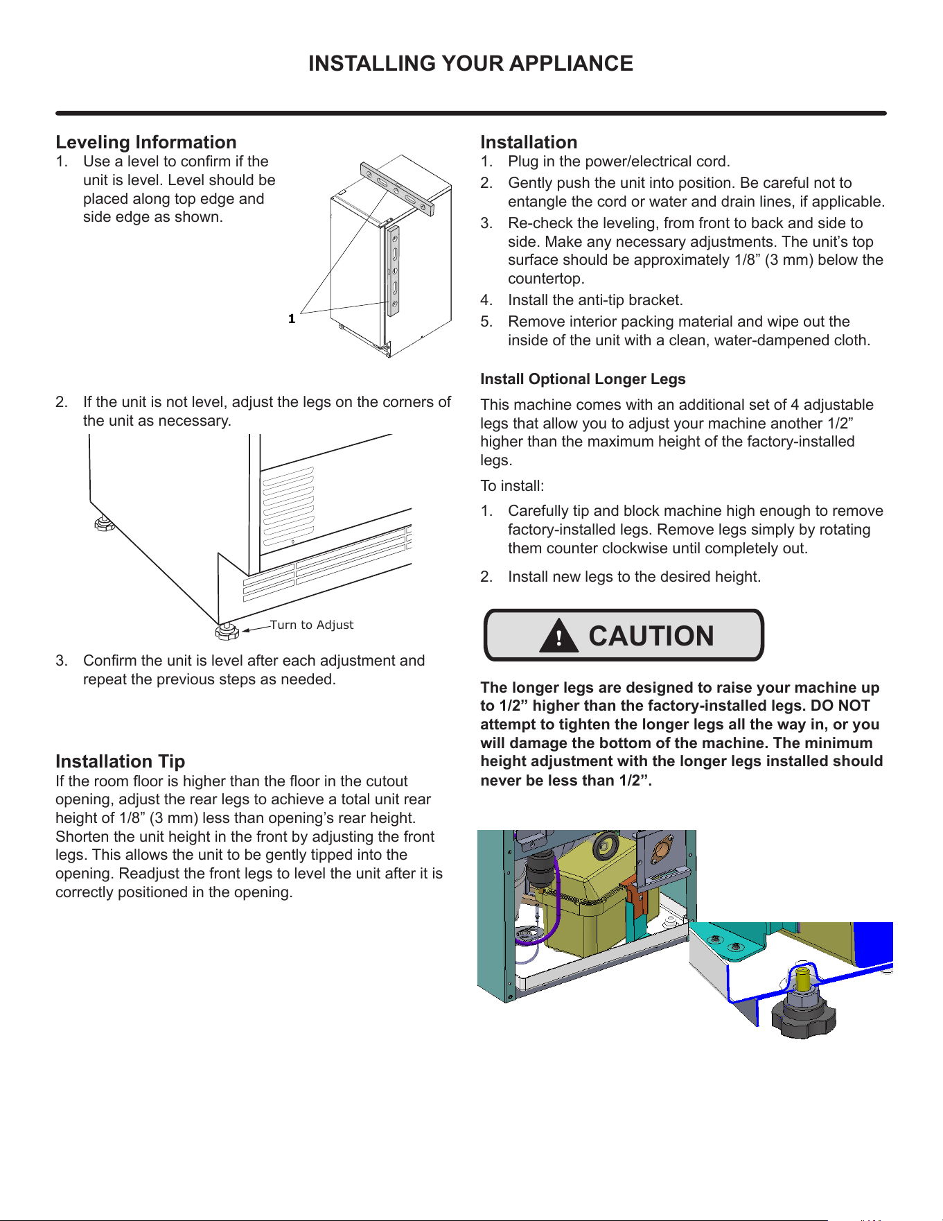
Leveling Information
1. Use a level to conrm if the
unit is level. Level should be
placed along top edge and
side edge as shown.
2. If the unit is not level, adjust the legs on the corners of
the unit as necessary.
3. Conrm the unit is level after each adjustment and
repeat the previous steps as needed.
1
Installation Tip
If the room oor is higher than the oor in the cutout
opening, adjust the rear legs to achieve a total unit rear
height of 1/8” (3 mm) less than opening’s rear height.
Shorten the unit height in the front by adjusting the front
legs. This allows the unit to be gently tipped into the
opening. Readjust the front legs to level the unit after it is
correctly positioned in the opening.
Installation
1. Plug in the power/electrical cord.
2. Gently push the unit into position. Be careful not to
entangle the cord or water and drain lines, if applicable.
3. Re-check the leveling, from front to back and side to
side. Make any necessary adjustments. The unit’s top
surface should be approximately 1/8” (3 mm) below the
countertop.
4. Install the anti-tip bracket.
5. Remove interior packing material and wipe out the
inside of the unit with a clean, water-dampened cloth.
Turn to Adjust
Install Optional Longer Legs
This machine comes with an additional set of 4 adjustable
legs that allow you to adjust your machine another 1/2”
higher than the maximum height of the factory-installed
legs.
To install:
1. Carefully tip and block machine high enough to remove
factory-installed legs. Remove legs simply by rotating
them counter clockwise until completely out.
2. Install new legs to the desired height.
The longer legs are designed to raise your machine up
to 1/2” higher than the factory-installed legs. DO NOT
attempt to tighten the longer legs all the way in, or you
will damage the bottom of the machine. The minimum
height adjustment with the longer legs installed should
!
CAUTION
never be less than 1/2”.
8
DOOR REVERSAL
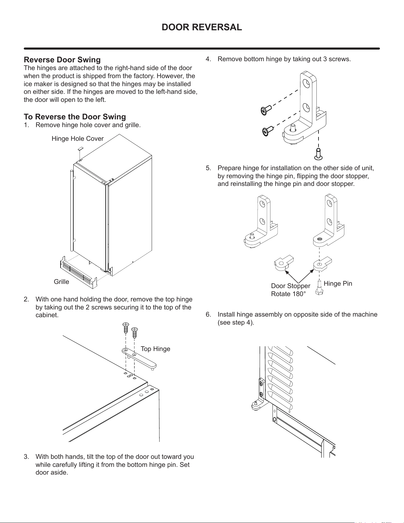
Reverse Door Swing
The hinges are attached to the right-hand side of the door
when the product is shipped from the factory. However, the
ice maker is designed so that the hinges may be installed
on either side. If the hinges are moved to the left-hand side,
the door will open to the left.
To Reverse the Door Swing
1. Remove hinge hole cover and grille.
2. With one hand holding the door, remove the top hinge
by taking out the 2 screws securing it to the top of the
cabinet.
3. With both hands, tilt the top of the door out toward you
while carefully lifting it from the bottom hinge pin. Set
door aside.
Grille
Top Hinge
4. Remove bottom hinge by taking out 3 screws.
5. Prepare hinge for installation on the other side of unit,
by removing the hinge pin, ipping the door stopper,
and reinstalling the hinge pin and door stopper.
6. Install hinge assembly on opposite side of the machine
(see step 4).
Hinge Pin
Door Stopper
Rotate 180°
Hinge Hole Cover
9
DOOR REVERSAL
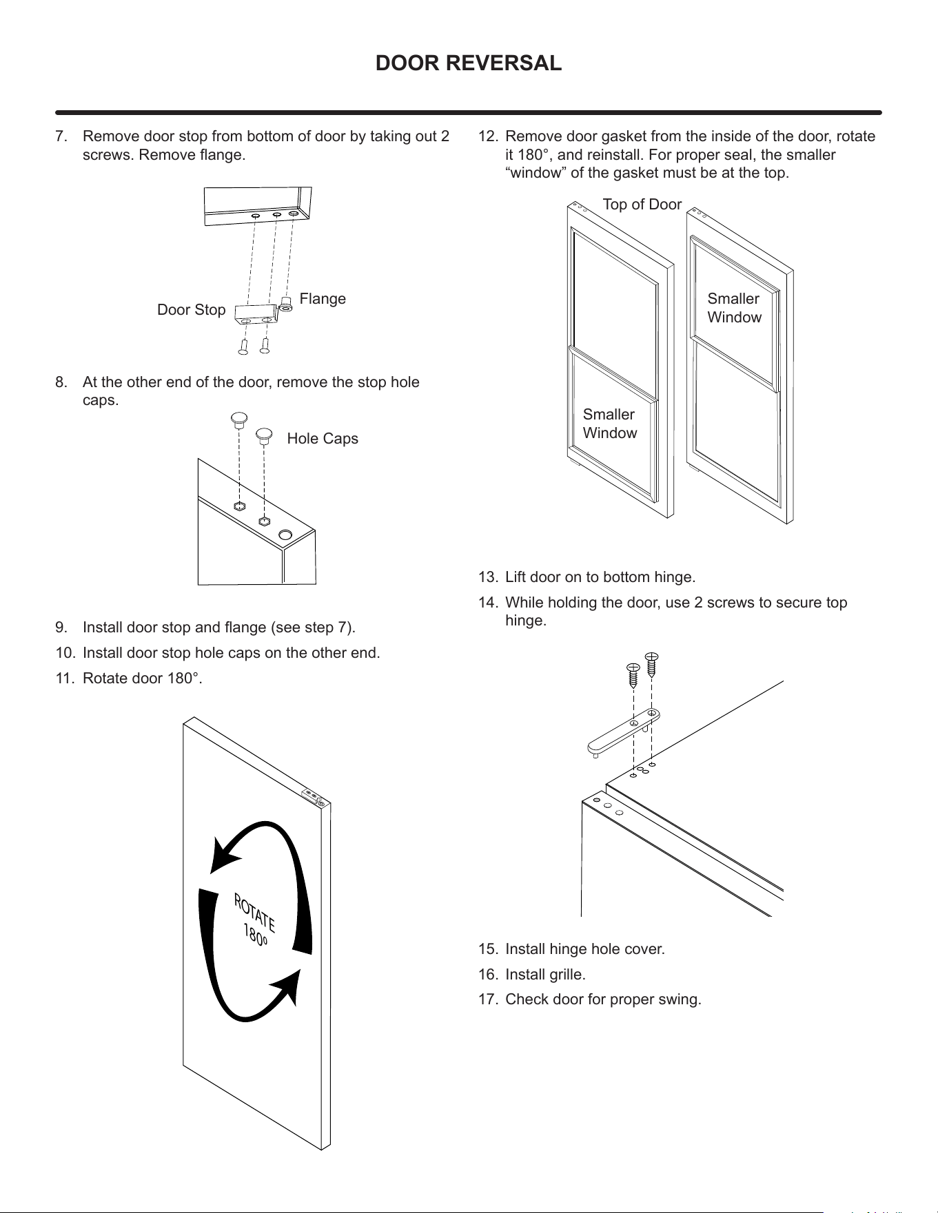
7. Remove door stop from bottom of door by taking out 2
screws. Remove ange.
8. At the other end of the door, remove the stop hole
caps.
9. Install door stop and ange (see step 7).
10. Install door stop hole caps on the other end.
11. Rotate door 180°.
Door Stop
Flange
Hole Caps
ROTATE
1800
12. Remove door gasket from the inside of the door, rotate
it 180°, and reinstall. For proper seal, the smaller
“window” of the gasket must be at the top.
13. Lift door on to bottom hinge.
14. While holding the door, use 2 screws to secure top
hinge.
15. Install hinge hole cover.
16. Install grille.
17. Check door for proper swing.
Top of Door
Smaller
Window
Smaller
Window
10
USING YOUR ELECTRONIC CONTROL
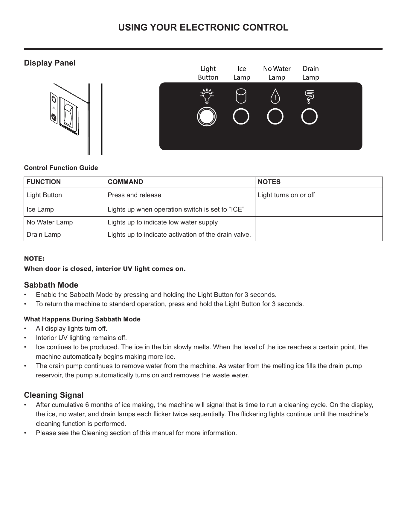
Display Panel
Control Function Guide
FUNCTION COMMAND NOTES
Light Button Press and release Light turns on or o
Ice Lamp Lights up when operation switch is set to “ICE”
No Water Lamp Lights up to indicate low water supply
Drain Lamp Lights up to indicate activation of the drain valve.
OFF
!
Light
Button
Ice
Lamp
No Water
Lamp
Drain
Lamp
NOTE:
When door is closed, interior UV light comes on.
Sabbath Mode
• Enable the Sabbath Mode by pressing and holding the Light Button for 3 seconds.
• To return the machine to standard operation, press and hold the Light Button for 3 seconds.
What Happens During Sabbath Mode
• All display lights turn o.
• Interior UV lighting remains o.
• Ice contiues to be produced. The ice in the bin slowly melts. When the level of the ice reaches a certain point, the
machine automatically begins making more ice.
• The drain pump continues to remove water from the machine. As water from the melting ice lls the drain pump
reservoir, the pump automatically turns on and removes the waste water.
Cleaning Signal
• After cumulative 6 months of ice making, the machine will signal that is time to run a cleaning cycle. On the display,
the ice, no water, and drain lamps each icker twice sequentially. The ickering lights continue until the machine’s
cleaning function is performed.
• Please see the Cleaning section of this manual for more information.
11
INSTALLING THE WATER SUPPLY
Water Hookup
Prepare Plumbing
Plan the arrangement of the water supply pipes.
Connect a 1/4” diameter copper waterline to the tap water
supply line. Install a shuto valve between the tap water
pipe and the product so that the user can operate the valve.
Do not install the shuto valve at the back of the product.
“Do not use a self-piercing valve. If the tap water has a high
level of minerals, a pipeline lter will be required.
The pressure of the tap water should be maintained at a
level between 20psi (1.4bar) and 80psi (5.5bar).
Plumbing installation must observe all state and local
codes. All water and drain connections MUST BE made by
a licensed/qualied plumbing contractor. Failure to follow
recommendations and instructions may result in damage
and/or harm.
Water Supply Connection
When connecting the water supply, please note the
following:
• Before installing the unit and connecting to the cold
water supply, review the local plumbing codes.
• Water has less than 400 mg/L (ppm) total dissolved
solids and hardness level below 200 mg/L (ppm) — i.e.,
below 12 grains per gallon. Check by using TDS meter
or consulting with local water company.
• Softened water is not recommended as it may result in
softer ice than desired.
• Connection to the water main is made with hose-set
only.
• Hose-set must be new, not reused, and in compliance
with IEC 61770.
• The water line MUST have a shut-o valve in the
supply line.
• The water line should be looped into 2 coils. This will
allow the unit to be removed for cleaning and servicing.
Make certain that the tubing is not pinched or damaged
during installation.
Do not use any plastic water supply line. The line is under
pressure at all times. Plastic may crack or rupture with age
and cause damage to your home.
!
CAUTION
!
CAUTION
Do not use tape or joint compound when attaching a
braided exible water supply line that includes a rubber
gasket. The gasket provides an adequate seal – other
materials could cause blockage of the valve.
Failure to follow recommendations and instructions may
result in damage and/or harm, ooding or void the product
warranty.
Use new hose set. Do not reuse old hose set.
Turn o water supply and disconnect electrical supply to
unit prior to installation.
Use caution when handling back panel. The edges could
be sharp.
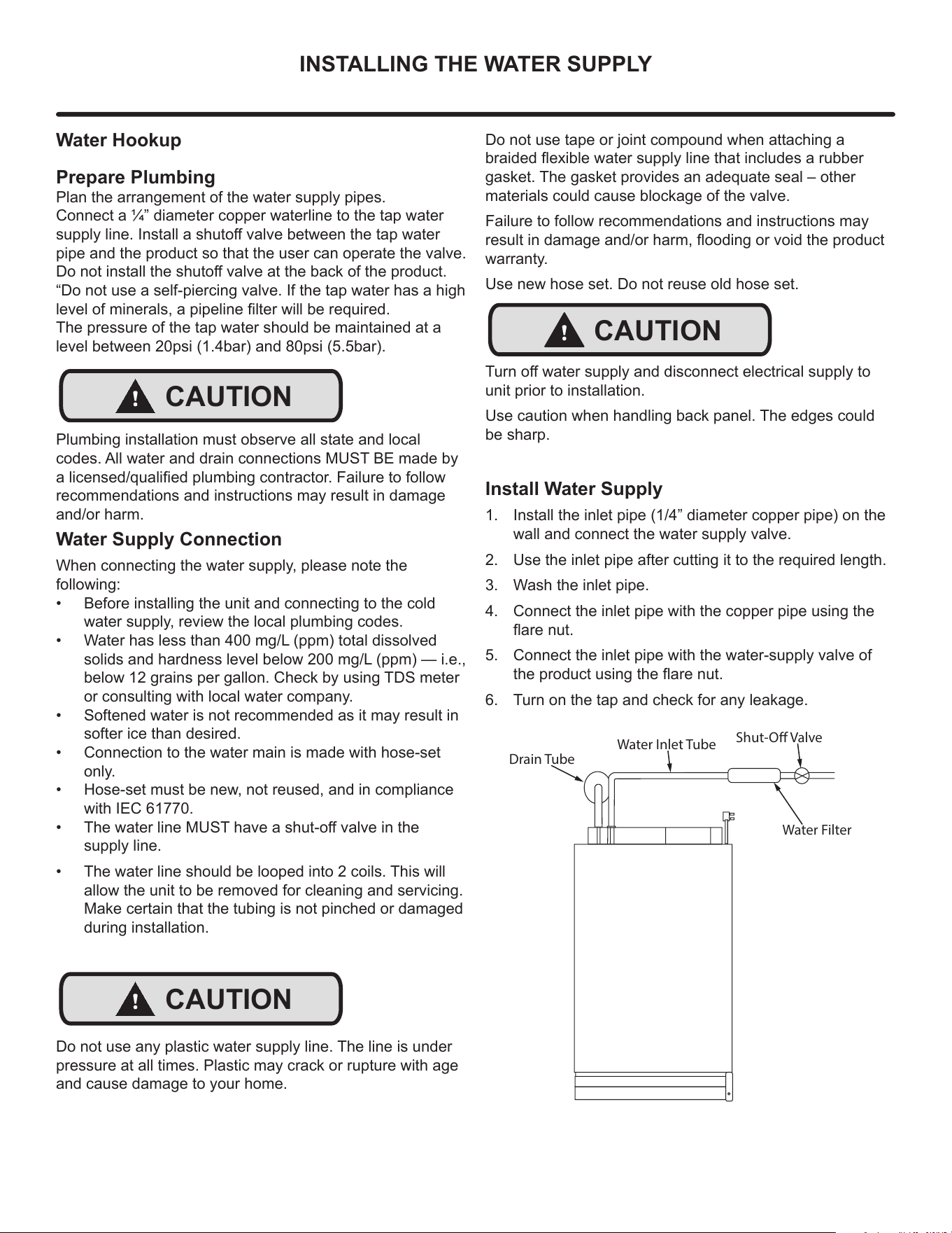
Install Water Supply
1. Install the inlet pipe (1/4” diameter copper pipe) on the
wall and connect the water supply valve.
2. Use the inlet pipe after cutting it to the required length.
3. Wash the inlet pipe.
4. Connect the inlet pipe with the copper pipe using the
are nut.
5. Connect the inlet pipe with the water-supply valve of
the product using the are nut.
6. Turn on the tap and check for any leakage.
Shut-O Valve
Water Filter
Drain Tube
Water Inlet Tube
!
CAUTION
12
Procedure for Testing Drain System
(both gravity and drain pump models)
Drain pump models have a safety feature that will interrupt power to the unit if a high-limit condition occurs to prevent
ooding. This safety feature can be initiated by a restriction in the drain system and will continue until high-limit condition
is corrected, at which time power will be restored to the unit. Power interruption can be detected when no icons are
visible in the display area of the user interface. Once power is returned, a startup chime will sound followed by a self-test,
and "OFF" should be visible in the display area.
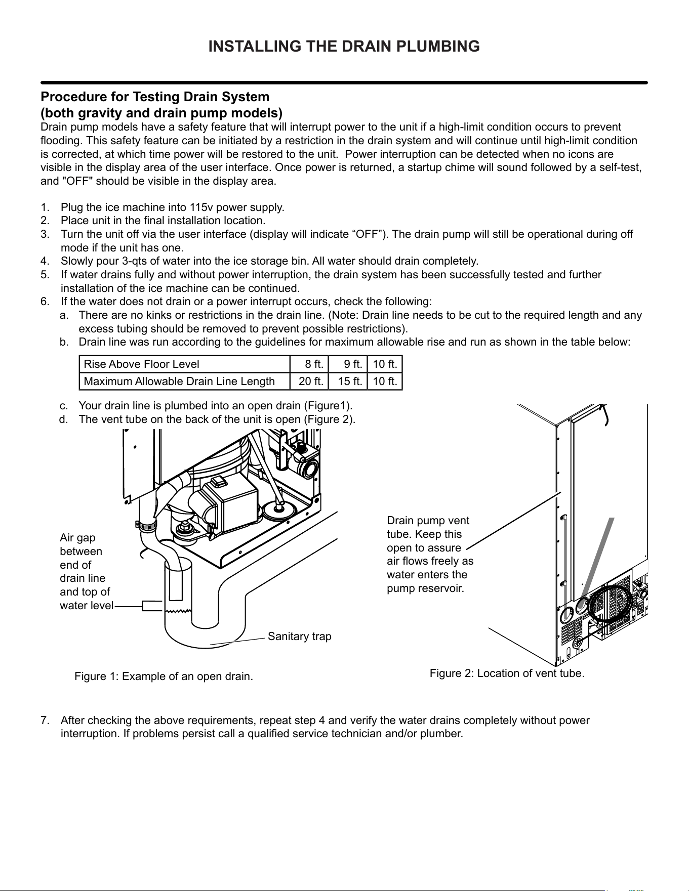
Drain pump vent
tube. Keep this
open to assure
air ows freely as
water enters the
pump reservoir.
Figure 2: Location of vent tube.
Figure 1: Example of an open drain.
Sanitary trap
1. Plug the ice machine into 115v power supply.
2. Place unit in the nal installation location.
3. Turn the unit off via the user interface (display will indicate “OFF”). The drain pump will still be operational during off
mode if the unit has one.
4. Slowly pour 3-qts of water into the ice storage bin. All water should drain completely.
5. If water drains fully and without power interruption, the drain system has been successfully tested and further
installation of the ice machine can be continued.
6. If the water does not drain or a power interrupt occurs, check the following:
a. There are no kinks or restrictions in the drain line. (Note: Drain line needs to be cut to the required length and any
excess tubing should be removed to prevent possible restrictions).
b. Drain line was run according to the guidelines for maximum allowable rise and run as shown in the table below:
Rise Above Floor Level 8 ft. 9 ft. 10 ft.
Maximum Allowable Drain Line Length 20 ft. 15 ft. 10 ft.
c. Your drain line is plumbed into an open drain (Figure1).
d. The vent tube on the back of the unit is open (Figure 2
).
7. After checking the above requirements, repeat step 4 and verify the water drains completely without power
interruption. If problems persist call a qualied service technician and/or plumber.
Air gap
between
end of
drain line
and top of
water level
INSTALLING THE DRAIN PLUMBING
13
INSTALLING THE DRAIN PLUMBING
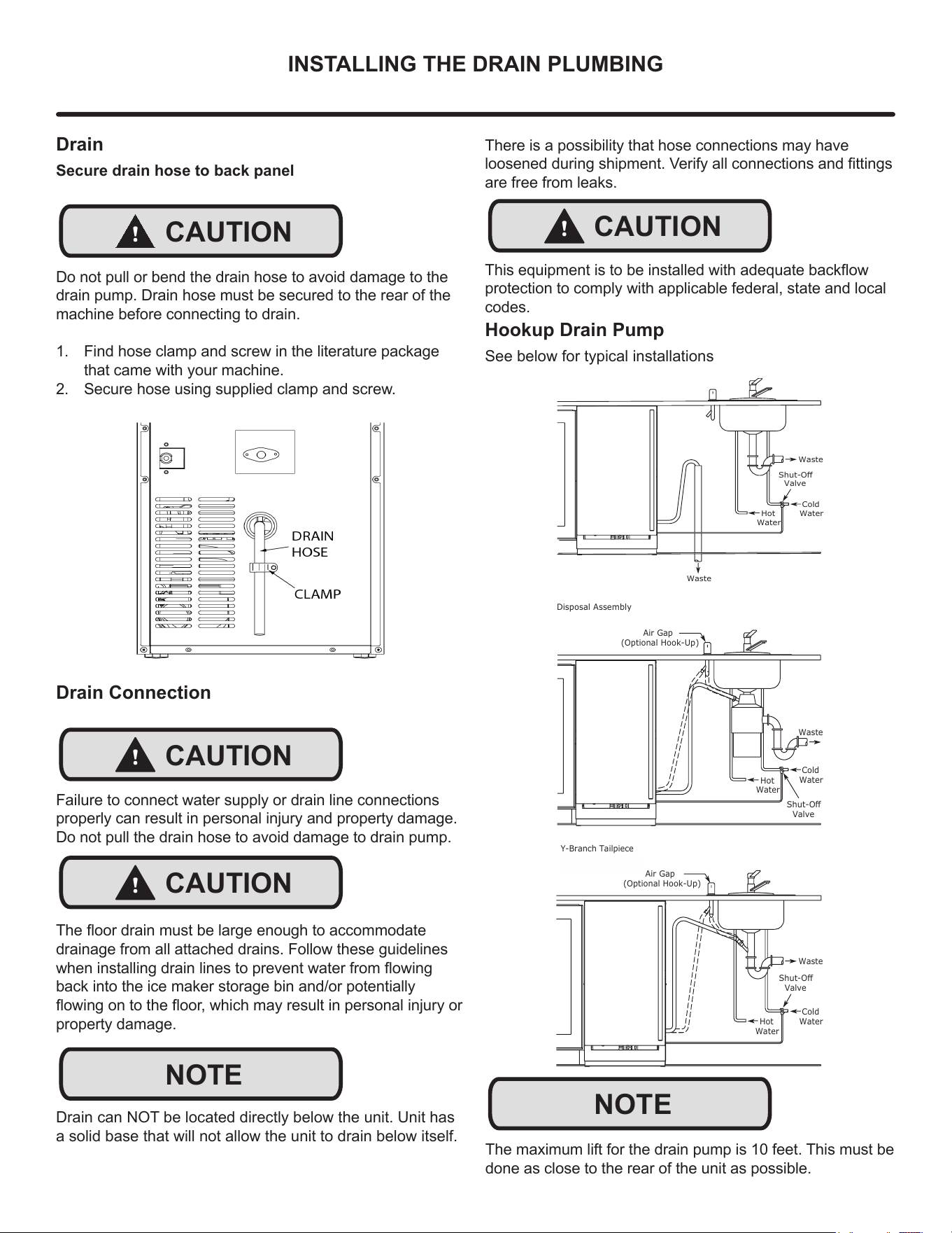
Drain
Secure drain hose to back panel
Do not pull or bend the drain hose to avoid damage to the
drain pump. Drain hose must be secured to the rear of the
machine before connecting to drain.
1. Find hose clamp and screw in the literature package
that came with your machine.
2. Secure hose using supplied clamp and screw.
!
CAUTION
NOTE
Cold
Water
Hot
Water
Waste
Waste
Shut-Off
Valve
Air Gap
(Optional Hook-Up)
Cold
Water
Hot
Water
Waste
Shut-Off
Valve
Disposal Assembly
Waste
Cold
Water
Shut-Off
Valve
Hot
Water
Air Gap
(Optional Hook-Up)
Y-Branch Tailpiece
P60 Pump Required
There is a possibility that hose connections may have
loosened during shipment. Verify all connections and ttings
are free from leaks.
Drain Connection
Failure to connect water supply or drain line connections
properly can result in personal injury and property damage.
Do not pull the drain hose to avoid damage to drain pump.
The oor drain must be large enough to accommodate
drainage from all attached drains. Follow these guidelines
when installing drain lines to prevent water from owing
back into the ice maker storage bin and/or potentially
owing on to the oor, which may result in personal injury or
property damage.
Drain can NOT be located directly below the unit. Unit has
a solid base that will not allow the unit to drain below itself.
!
CAUTION
!
CAUTION
NOTE
!
CAUTION
This equipment is to be installed with adequate backow
protection to comply with applicable federal, state and local
codes.
Hookup Drain Pump
See below for typical installations
The maximum lift for the drain pump is 10 feet. This must be
done as close to the rear of the unit as possible.
14
ICE MAKER OPERATION
Ice
Do not put anything other than ice in the ice bin. Wine or
beer bottles are unsanitary and a detached label may block
the drain.
If the ice storage bin is full of water, turn o the ice maker
and clean the mesh on the bottom of the ice bin.
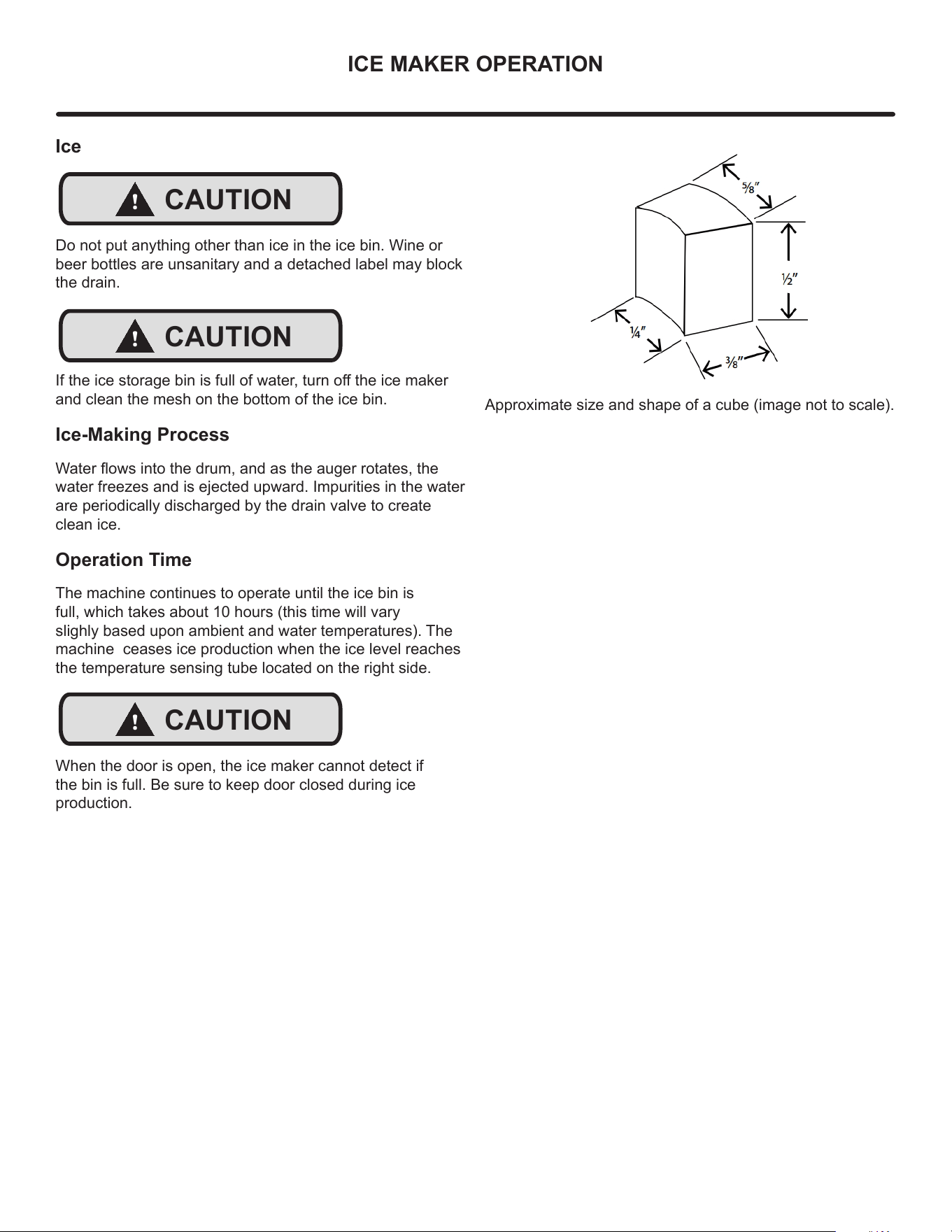
Ice-Making Process
Water ows into the drum, and as the auger rotates, the
water freezes and is ejected upward. Impurities in the water
are periodically discharged by the drain valve to create
clean ice.
Operation Time
The machine continues to operate until the ice bin is
full, which takes about 10 hours (this time will vary
slighly based upon ambient and water temperatures). The
machine ceases ice production when the ice level reaches
the temperature sensing tube located on the right side.
When the door is open, the ice maker cannot detect if
the bin is full. Be sure to keep door closed during ice
production.
!
CAUTION
!
CAUTION
!
CAUTION
Approximate size and shape of a cube (image not to scale).
15
CARE & CLEANING
Cleaning
Use only Marvel Ice Machine Cleaner (S41013789),
available for purchase from marvelrefrigeration.com or
your dealer. It is a violation of federal law to use this
solution in a manner inconsistent with its labeling. Use
of any other cleaner can cause damage to the ice ma-
chine and will void the warranty. Read and understand
all labels printed on the package before use.
Marvel Ice Machine Cleaner is used to remove lime
scale and other mineral deposits. Refer to the
following steps to initiate the self-cleaning cycle.
Internal Cleaning
Cleaning Signal
• After cumulative 6 months of ice making, the machine
will signal that is time to run a cleaning cycle. On the
display, the ice, no water, and drain lamps each icker
twice sequentially. The ickering lights continue until
the machine’s cleaning function is performed.
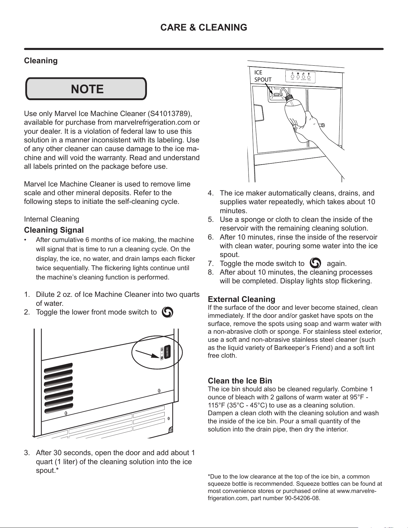
1. Dilute 2 oz. of Ice Machine Cleaner into two quarts
of water.
2. Toggle the lower front mode switch to
3. After 30 seconds, open the door and add about 1
quart (1 liter) of the cleaning solution into the ice
spout.*
NOTE
OFF
4. The ice maker automatically cleans, drains, and
supplies water repeatedly, which takes about 10
minutes.
5. Use a sponge or cloth to clean the inside of the
reservoir with the remaining cleaning solution.
6. After 10 minutes, rinse the inside of the reservoir
with clean water, pouring some water into the ice
spout.
7. Toggle the mode switch to again.
8. After about 10 minutes, the cleaning processes
will be completed. Display lights stop ickering.
External Cleaning
If the surface of the door and lever become stained, clean
immediately. If the door and/or gasket have spots on the
surface, remove the spots using soap and warm water with
a non-abrasive cloth or sponge. For stainless steel exterior,
use a soft and non-abrasive stainless steel cleaner (such
as the liquid variety of Barkeeper’s Friend) and a soft lint
free cloth.
Clean the Ice Bin
The ice bin should also be cleaned regularly. Combine 1
ounce of bleach with 2 gallons of warm water at 95°F -
115°F (35°C - 45°C) to use as a cleaning solution.
Dampen a clean cloth with the cleaning solution and wash
the inside of the ice bin. Pour a small quantity of the
solution into the drain pipe, then dry the interior.
*Due to the low clearance at the top of the ice bin, a common
squeeze bottle is recommended. Squeeze bottles can be found at
most convenience stores or purchased online at www.marvelre-
frigeration.com, part number 90-54206-08.
LAMP
ICE
NO WATER
DRAIN
ICE
SPOUT
16
CARE & CLEANING
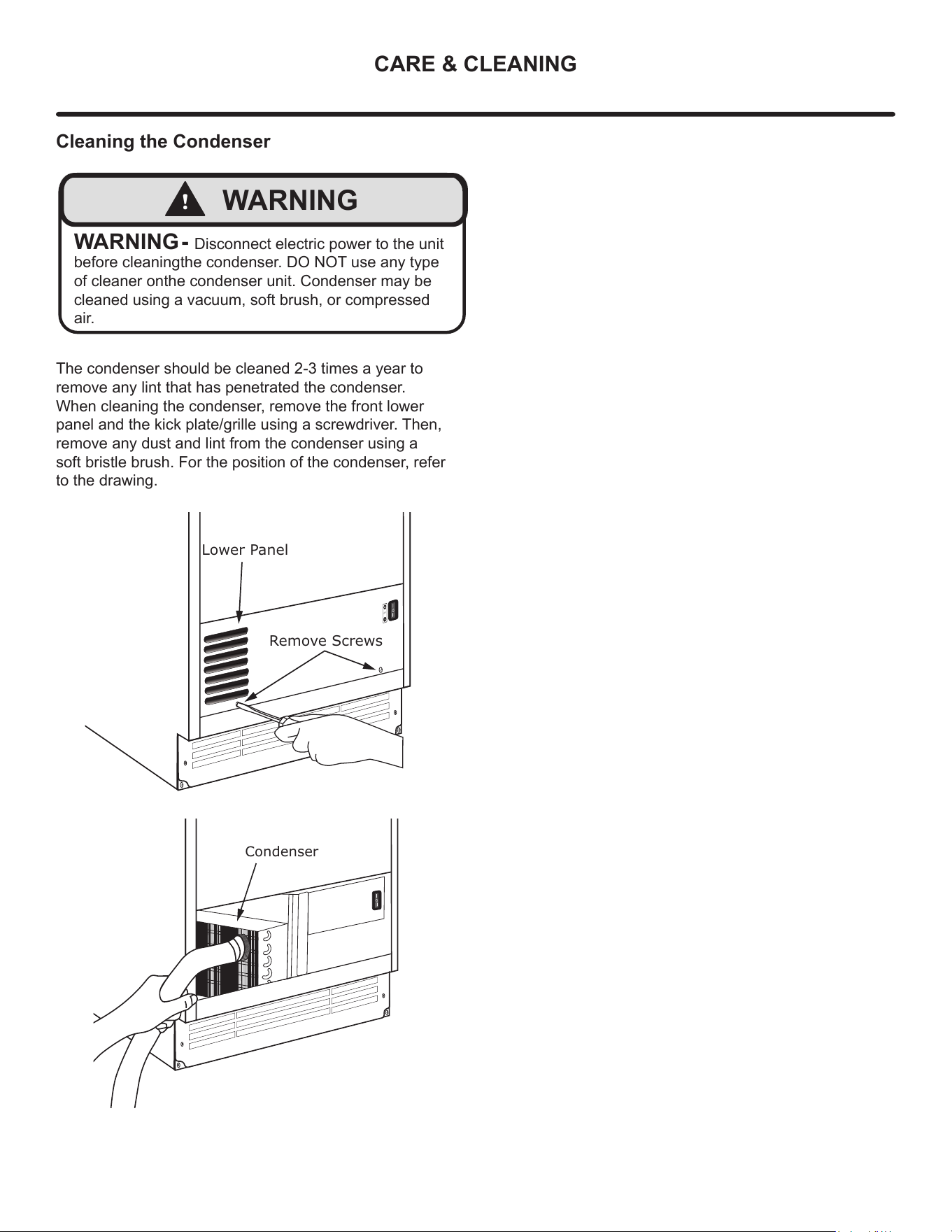
Cleaning the Condenser
The condenser should be cleaned 2-3 times a year to
remove any lint that has penetrated the condenser.
When cleaning the condenser, remove the front lower
panel and the kick plate/grille using a screwdriver. Then,
remove any dust and lint from the condenser using a
soft bristle brush. For the position of the condenser, refer
to the drawing.
OFF
Remove Screws
Lower Panel
Condenser
!
WARNING
WARNING - Disconnect electric power to the unit
before cleaningthe condenser. DO NOT use any type
of cleaner onthe condenser unit. Condenser may be
cleaned using a vacuum, soft brush, or compressed
air.
17
OBTAINING SERVICE
If Service is Required:
• If the product is within the rst year warranty period,
please go to marvelrefrigeration.com/request-prod-
uct-service or call Marvel Customer Service at
616.754.5601 for directions on how to obtain warranty
coverage in your area.
• If the product is outside the rst year warran-
ty period, Marvel Customer Service can provide
recommendations of service centers in your area. A
listing of authorized service centers is also available
at www.marvelrefrigeration.com under the service and
support section.
• In all correspondence regarding service, be sure to
give the service number, serial number, and proof of
purchase.
• Try to have information or description of nature of the
problem, how long the appliance has been running, the
room temperature, and any additional information that
may be helpful in quickly solving the problem.
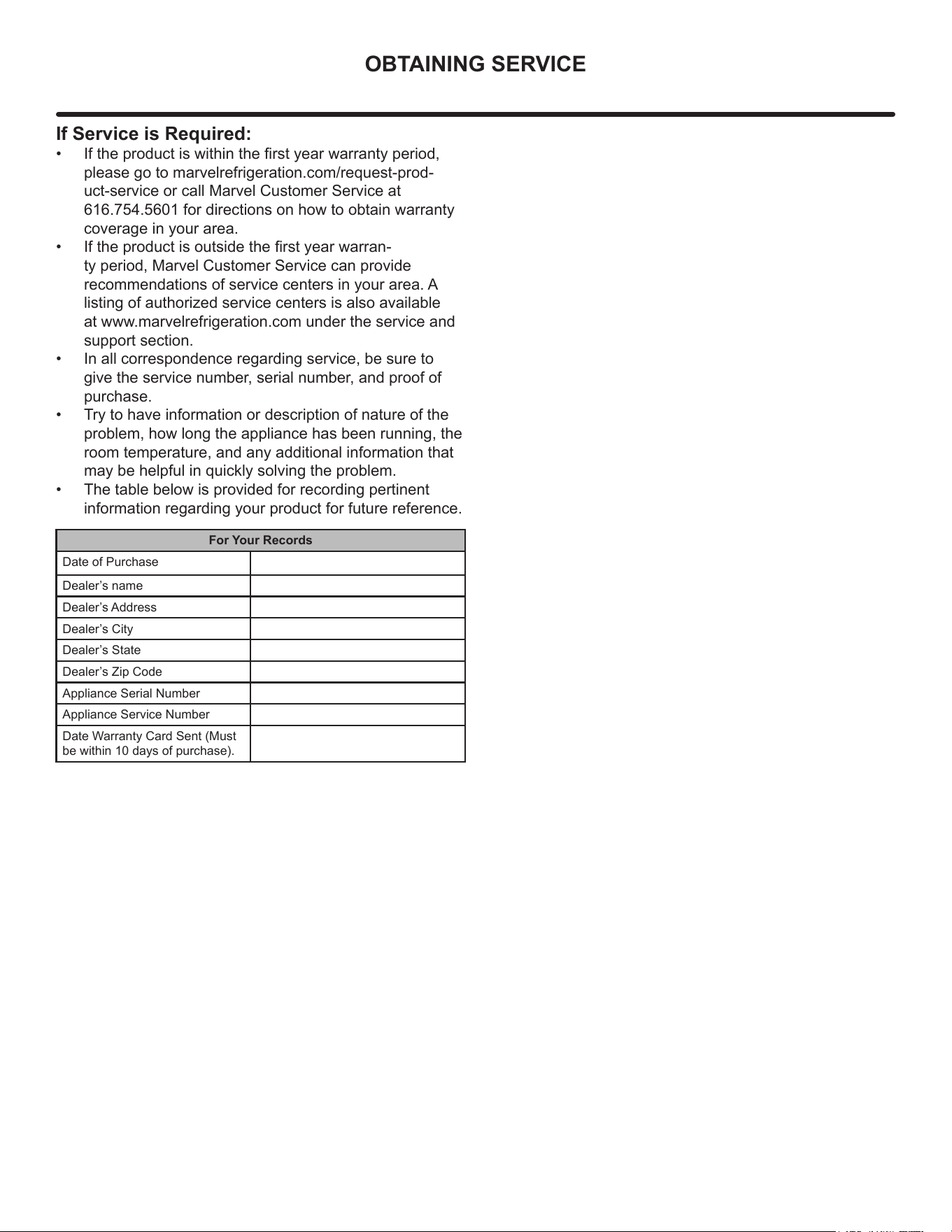
• The table below is provided for recording pertinent
information regarding your product for future reference.
For Your Records
Date of Purchase
Dealer’s name
Dealer’s Address
Dealer’s City
Dealer’s State
Dealer’s Zip Code
Appliance Serial Number
Appliance Service Number
Date Warranty Card Sent (Must
be within 10 days of purchase).
18
TROUBLESHOOTING
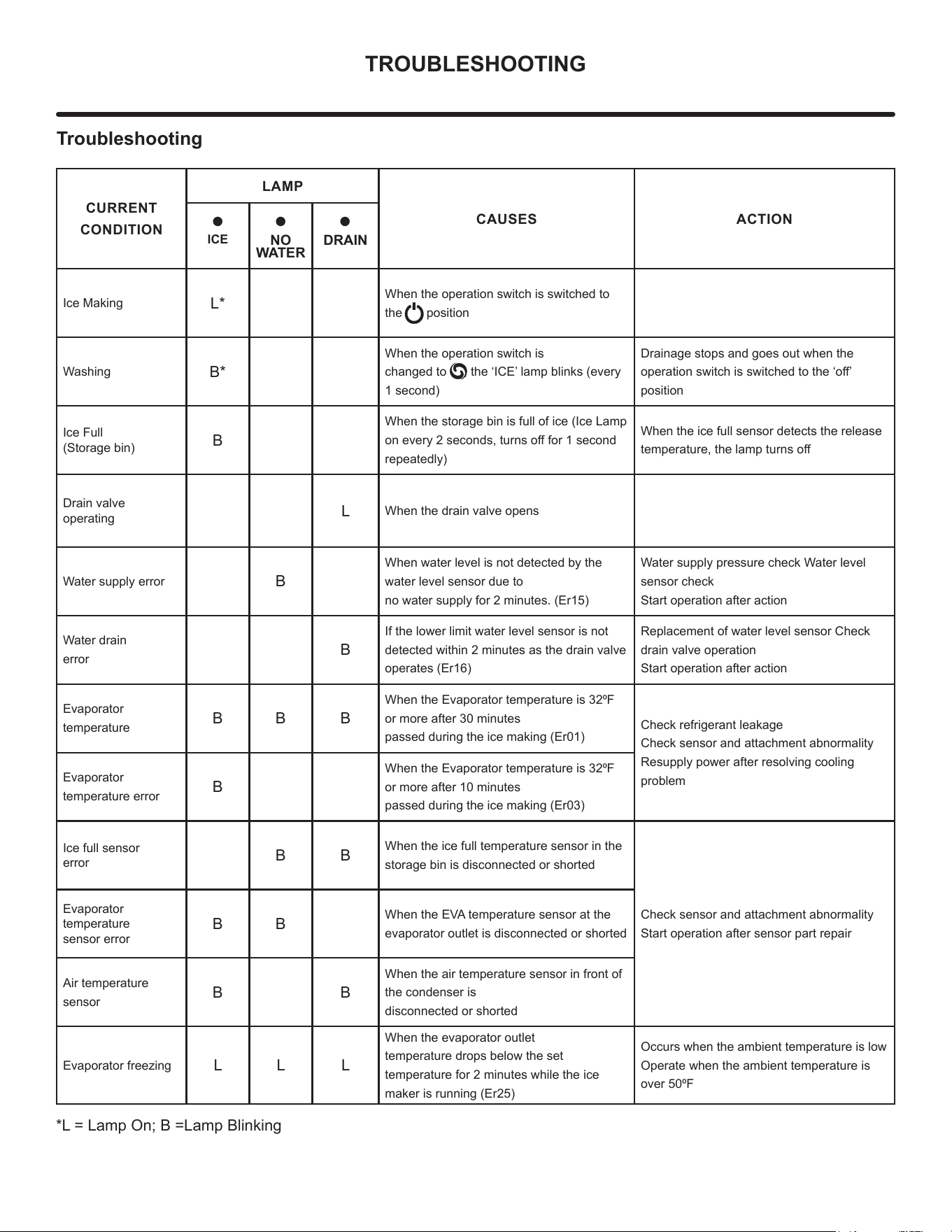
Troubleshooting
CURRENT
CONDITION
LAMP
CAUSES ACTION
•
ICE
•
NO
WATER
•
DRAIN
Ice Making
L*
When the operation switch is switched to
the position
Washing
B*
When the operation switch is
changed to , the ‘ICE’ lamp blinks (every
1 second)
Drainage stops and goes out when the
operation switch is switched to the ‘o’
position
Ice Full
(Storage bin)
B
When the storage bin is full of ice (Ice Lamp
on every 2 seconds, turns o for 1 second
repeatedly)
When the ice full sensor detects the release
temperature, the lamp turns o
Drain valve
operating
L
When the drain valve opens
Water supply error
B
When water level is not detected by the
water level sensor due to
no water supply for 2 minutes. (Er15)
Water supply pressure check Water level
sensor check
Start operation after action
Water drain
error
B
If the lower limit water level sensor is not
detected within 2 minutes as the drain valve
operates (Er16)
Replacement of water level sensor Check
drain valve operation
Start operation after action
Evaporator
temperature
B B B
When the Evaporator temperature is 320F
or more after 30 minutes
passed during the ice making (Er01)
Check refrigerant leakage
Check sensor and attachment abnormality
Resupply power after resolving cooling
problem
Evaporator
temperature error
B
When the Evaporator temperature is 320F
or more after 10 minutes
passed during the ice making (Er03)
Ice full sensor
error
B B
When the ice full temperature sensor in the
storage bin is disconnected or shorted
Check sensor and attachment abnormality
Start operation after sensor part repair
Evaporator
temperature
sensor error
B B
When the EVA temperature sensor at the
evaporator outlet is disconnected or shorted
Air temperature
sensor
B B
When the air temperature sensor in front of
the condenser is
disconnected or shorted
Evaporator freezing
L L L
When the evaporator outlet
temperature drops below the set
temperature for 2 minutes while the ice
maker is running (Er25)
Occurs when the ambient temperature is low
Operate when the ambient temperature is
over 500F
*L = Lamp On; B =Lamp Blinking
19
TROUBLESHOOTING
1188
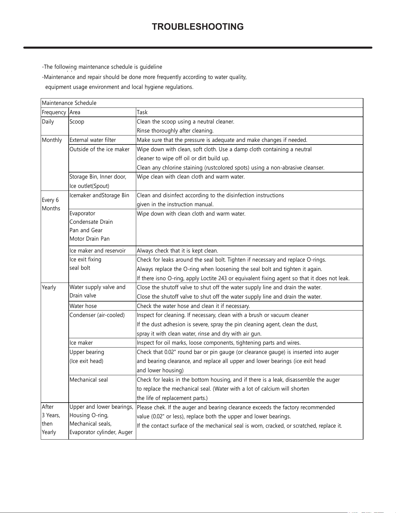
8. Maintenance Schedule
-The following maintenance schedule is guideline
-Maintenance and repair should be done more frequently according to water quality,
equipment usage environment and local hygiene regulations.
Maintenance Schedule
Frequency Area Task
Daily Scoop Clean the scoop using a neutral cleaner.
Rinse thoroughly after cleaning.
Monthly External water filter Make sure that the pressure is adequate and make changes if needed.
Outside of the ice maker
Wipe down with clean, soft cloth. Use a damp cloth containing a neutral
cleaner to wipe off oil or dirt build up.
Clean any chlorine staining (rust colored spots) using a non-abrasive cleanser.
Storage Bin, Inner door, Wipe clean with clean cloth and warm water.
Ice outlet(Spout)
Icemaker and Storage Bin Clean and disinfect according to the disinfection instructions
given in the instruction manual.
Wipe down with clean cloth and warm water.
Ice maker and reservoir Always check that it is kept clean.
Check for leaks around the seal bolt. Tighten if necessary and replace O-rings.
Always replace the O-ring when loosening the seal bolt and tighten it again.
If there is no O-ring, apply Loctite 243 or equivalent fixing agent so that it does not leak.
Yearly Close the shutoff valve to shut off the water supply line and drain the water.
Close the shutoff valve to shut off the water supply line and drain the water.
Water hose Check the water hose and clean it if necessary.
Condenser (air-cooled) Inspect for cleaning. If necessary, clean with a brush or vacuum cleaner
If the dust adhesion is severe, spray the pin cleaning agent, clean the dust,
spray it with clean water, rinse and dry with air gun.
Ice maker Inspect for oil marks, loose components, tightening parts and wires.
Upper bearing Check that 0.02" round bar or pin gauge (or clearance gauge) is inserted into auger
(Ice exit head) and bearing clearance, and replace all upper and lower bearings (ice exit head
and lower housing)
Mechanical seal Check for leaks in the bottom housing, and if there is a leak, disassemble the auger
to replace the mechanical seal. (Water with a lot of calcium will shorten
the life of replacement parts.)
Please chek. If the auger and bearing clearance exceeds the factory recommended
value (0.02" or less), replace both the upper and lower bearings.
If the contact surface of the mechanical seal is worn, cracked, or scratched, replace it.
Every 6
Months
After
3 Years,
then
Yearly
Evaporator
Condensate Drain
Pan and Gear
Motor Drain Pan
Ice exit fixing
seal bolt
Water supply valve and
Drain valve
Upper and lower bearings,
Housing O-ring,
Mechanical seals,
Evaporator cylinder, Auger
20
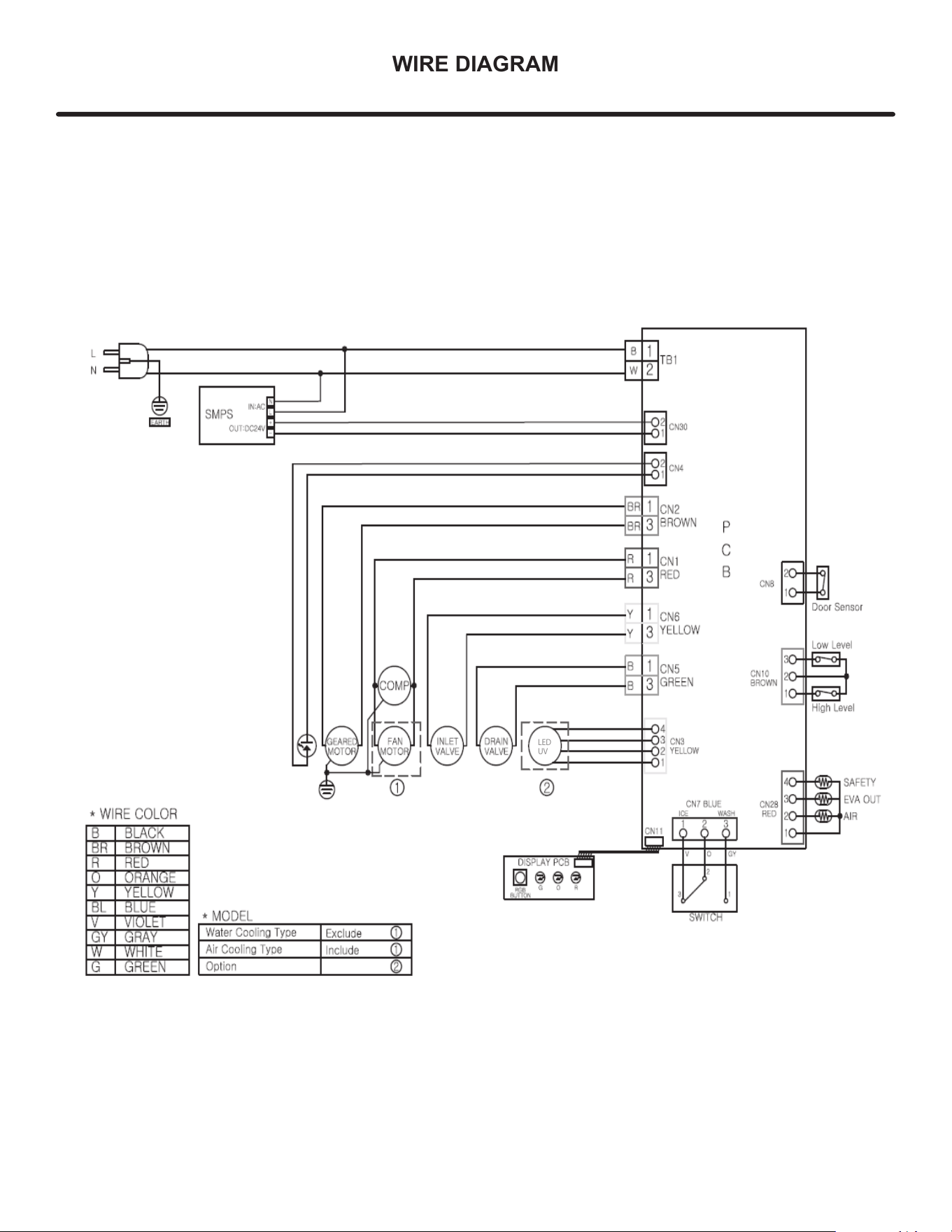
WIRE DIAGRAM
LED
UV
21
PRODUCT LIABILITY
Field service technicians are authorized to make an initial
assessment in the event of reported damages. If there are
any questions about the process involved, the technician
should call Marvel for further explanation.
While inspecting for defects or installation issues, photos
should be taken to document any damages or issues
found.
During the assessment, if the service technician is able to
nd the source of the damage and it can be resolved by
replacement of a part, the servicer is authorized to replace
the part in question. The part that caused the damage
must be returned to Marvel in its entirety. The part must
be clearly labeled with the serial number of the unit it was
removed from, the date, and the servicer who removed the
part.
If the service technician determines the damage is the
result of installation issues (water connection/drain, etc.),
the consumer would be notied and the issues shall be
resolved at the direction of the consumer.
If damage is evident and the service technician is
unable to nd the source, Marvel must be contacted at
616.754.5601 for further direction.
1260 E. Van Deinse St. • Greenville, MI 48838
T: 616.754.5601
Website: www.marvelrefrigeration.com
The original refrigeration experts since 1892.
22
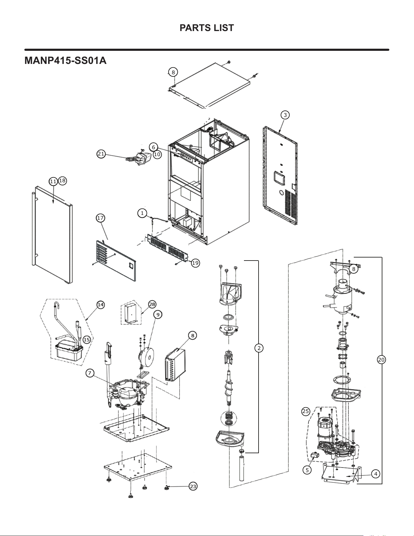
PARTS LIST
7
8
28
14
15
9
1
3
6
10
11
18
17
21
8
19
2
4
5
25
8
20
MANP415-SS01A
23
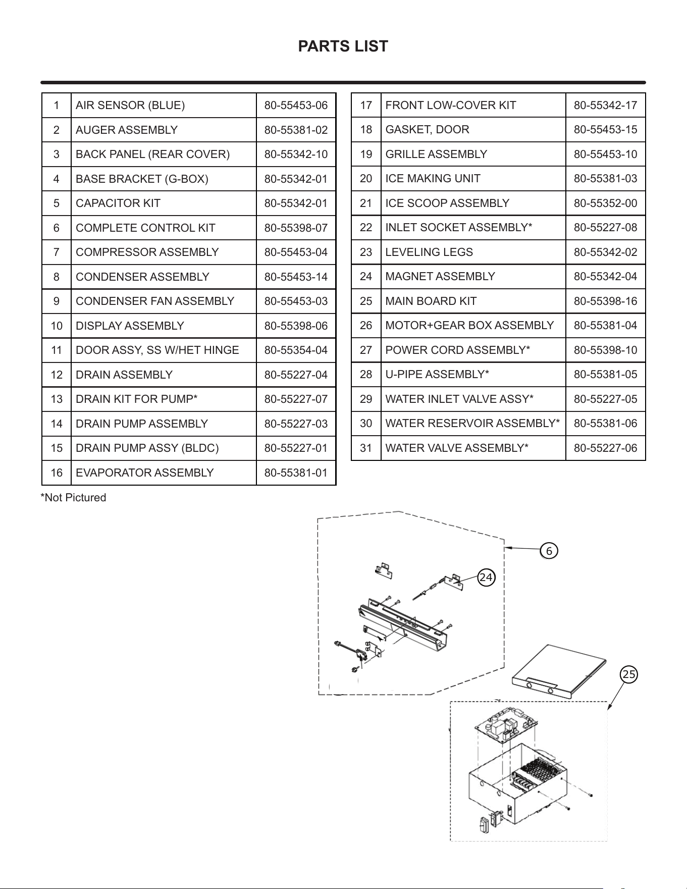
PARTS LIST
1 AIR SENSOR (BLUE) 80-55453-06
2 AUGER ASSEMBLY 80-55381-02
3 BACK PANEL (REAR COVER) 80-55342-10
4 BASE BRACKET (G-BOX) 80-55342-01
5 CAPACITOR KIT 80-55342-01
6 COMPLETE CONTROL KIT 80-55398-07
7 COMPRESSOR ASSEMBLY 80-55453-04
8 CONDENSER ASSEMBLY 80-55453-14
9 CONDENSER FAN ASSEMBLY 80-55453-03
10 DISPLAY ASSEMBLY 80-55398-06
11 DOOR ASSY, SS W/HET HINGE 80-55354-04
12 DRAIN ASSEMBLY 80-55227-04
13 DRAIN KIT FOR PUMP* 80-55227-07
14 DRAIN PUMP ASSEMBLY 80-55227-03
15 DRAIN PUMP ASSY (BLDC) 80-55227-01
16 EVAPORATOR ASSEMBLY 80-55381-01
17 FRONT LOW-COVER KIT 80-55342-17
18 GASKET, DOOR 80-55453-15
19 GRILLE ASSEMBLY 80-55453-10
20 ICE MAKING UNIT 80-55381-03
21 ICE SCOOP ASSEMBLY 80-55352-00
22 INLET SOCKET ASSEMBLY* 80-55227-08
23 LEVELING LEGS 80-55342-02
24 MAGNET ASSEMBLY 80-55342-04
25 MAIN BOARD KIT 80-55398-16
26 MOTOR+GEAR BOX ASSEMBLY 80-55381-04
27 POWER CORD ASSEMBLY* 80-55398-10
28 U-PIPE ASSEMBLY* 80-55381-05
29 WATER INLET VALVE ASSY* 80-55227-05
30 WATER RESERVOIR ASSEMBLY* 80-55381-06
31 WATER VALVE ASSEMBLY* 80-55227-06
28
24
6
25
*Not Pictured
24
ORDERING REPLACEMENT PARTS
Parts may be ordered online at partsformarvel.com.
Or contact:
www.marvelrefrigeration.com (Servicers choose "Login" for
service account).
Phone Number: (616) 754-5601
NOTE
Use only genuine Marvel replacement parts. The
use of non-Marvel parts can reduce performance,
damage the unit, and void the warranty.
Warranty parts will be shipped at no charge after Marvel
conrms warranty status. Please provide the model, serial
number, part number and part description. Some parts will
require color or voltage information.
Marvel requires the return of original parts, we will inform
you when the parts order is taken. This requirement will
be noted on your packing list. A prepaid shipping label will
be emailed to you. Please enclose a copy of the parts
packing list and be sure the model and serial numbers are
legible on the paperwork. Tag the part with the reported
defect.
Customers and non-authorized servicers may order non-
warranty parts at www.partsformarvel.com. Authorized
servicers with a servicer login may order non-warranty
parts at www.marvelrefrigeration.com.
25
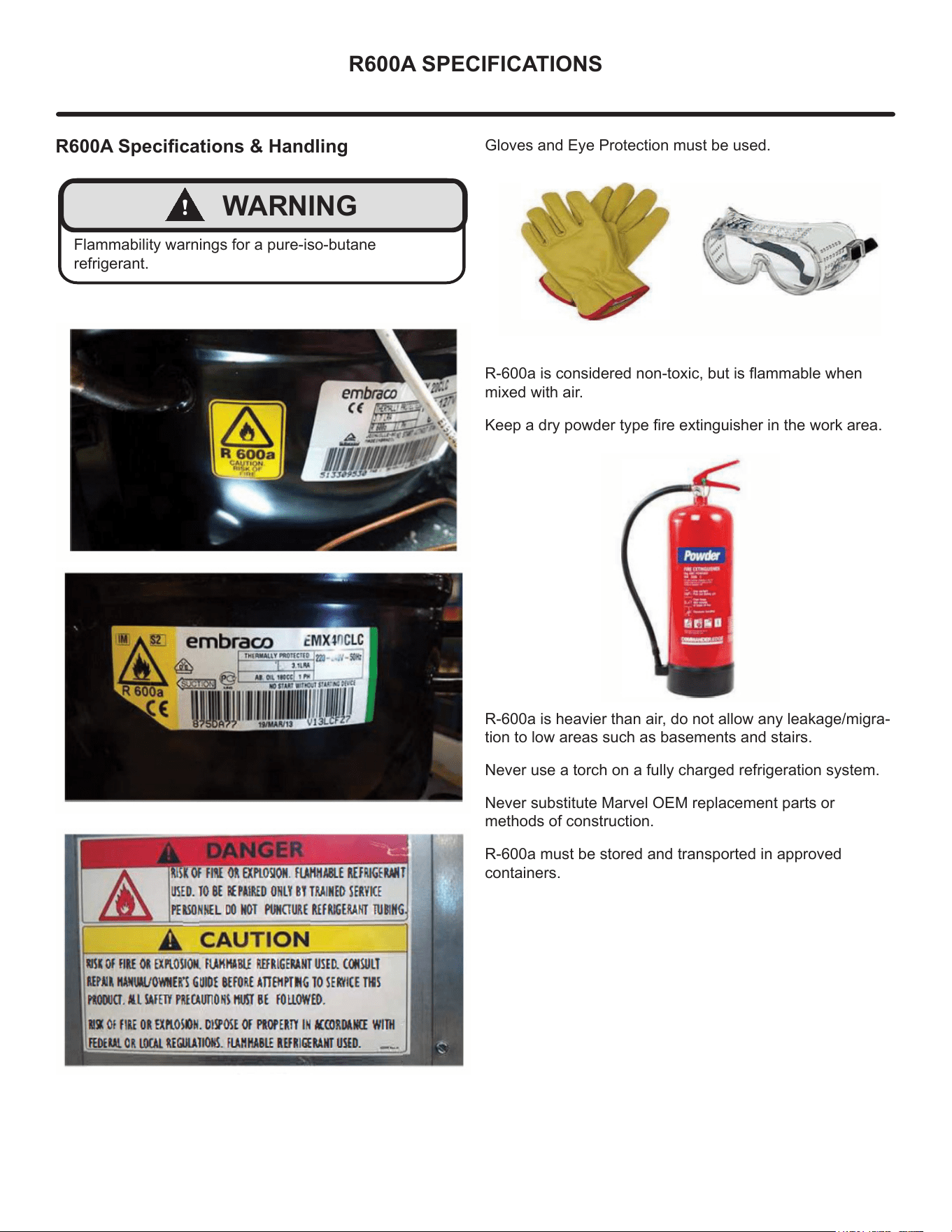
R600A SPECIFICATIONS
R600A Specications & Handling
!
WARNING
Flammability warnings for a pure-iso-butane
refrigerant.
Gloves and Eye Protection must be used.
R-600a is considered non-toxic, but is ammable when
mixed with air.
Keep a dry powder type re extinguisher in the work area.
R-600a is heavier than air, do not allow any leakage/migra-
tion to low areas such as basements and stairs.
Never use a torch on a fully charged refrigeration system.
Never substitute Marvel OEM replacement parts or
methods of construction.
R-600a must be stored and transported in approved
containers.
26
R600A SPECIFICATIONS
!
WARNING
Only skilled and well trained service technicians
permitted to service R-600a equipped products.
All tools and equipment must be approved for use with
R-600a refrigerant.
Local, state and federal laws, standards must be
observed along with proper certication and licensing.
Ventilation is required during servicing.
No conversions to R-600a from any other refrigerants.
OEM R-600a equipped unit only.
Service area must be free of ignition sources.
No smoking is allowed in the service area.
All replacement electrical components must be OEM
and installed properly (sealed and covered).
If the evaporator is cold prior to service, it must be
thawed prior to service.
When using a vacuum pump, start pump before
opening refrigeration system.
Vacuum pump and recovery equipment should be at
least 10 feet from the work area.
It is recommended that a simple LPG gas detector is
on site during service.
Ensure that all R-600a is removed from the system
prior to brazing any part of the sealed system.
Only a clean, dry leak free system should be charged
with R-600a.
R-600A Specications/Labeling
R-600a equipped products are labeled (both the unit and
the compressor).
R-600a is colorless and odorless.
R-600a is considered non-toxic, but is ammable when
mixed with air.
Do not remove or alter any R-600a labeling on the product.
Use only a refrigerant grade R-600a from a properly
labeled container.
Recovering/Reclaiming R-600A
(R-600a has been exempted from recovery/reclaiming
requirements by the US EPA)
Recovery/Reclaiming equipment must be approved for use
with R-600a.
Ensure the evaporator is at room temperature prior to
recovery/reclaiming R-600a.
Use a common piercing pliers or piercing valve to remove
R-600a from the compressor process tube. (Note: Pierc-
ing devices must not be left on the system and must be
replaced with a Schrader type valve).
27
R600A SPECIFICATIONS
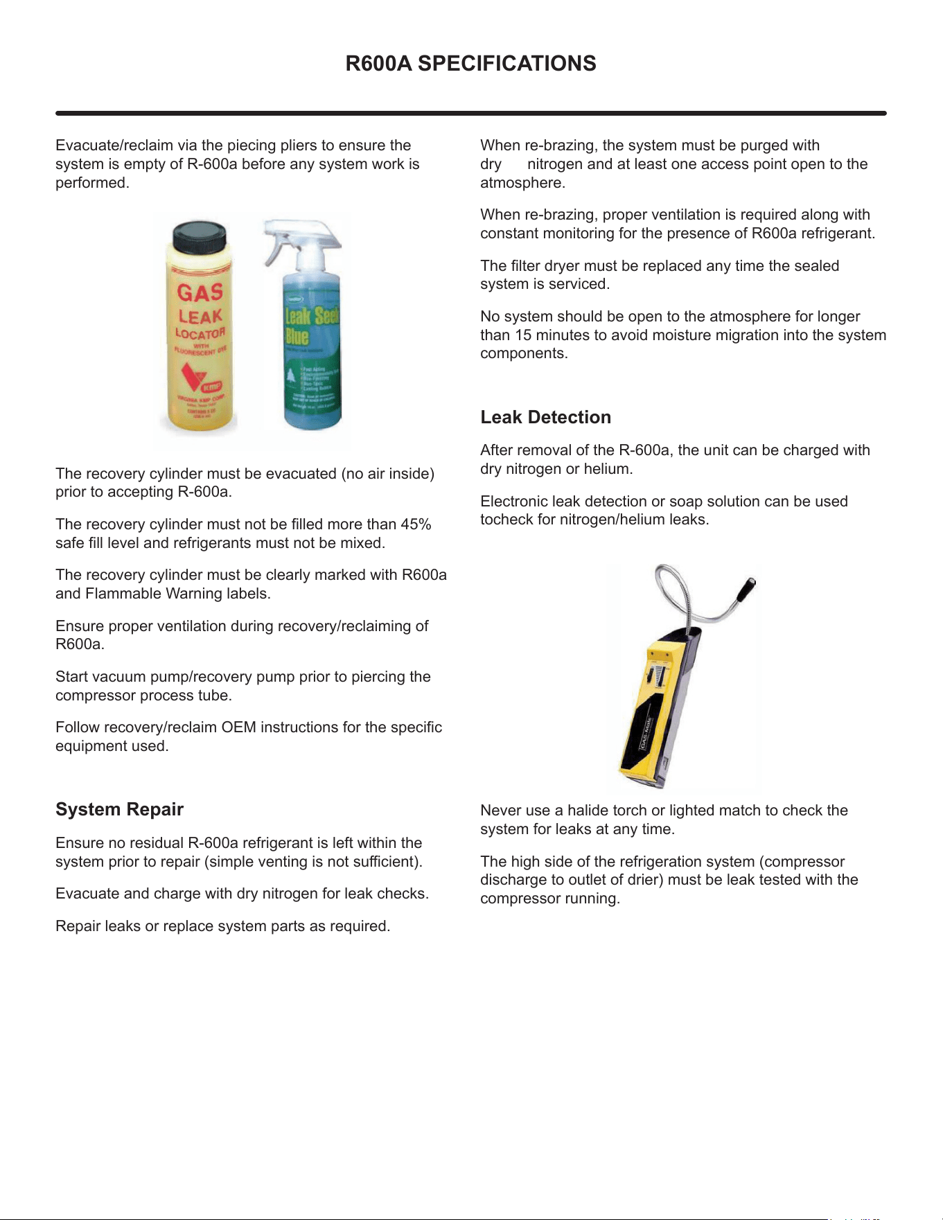
Evacuate/reclaim via the piecing pliers to ensure the
system is empty of R-600a before any system work is
performed.
The recovery cylinder must be evacuated (no air inside)
prior to accepting R-600a.
The recovery cylinder must not be lled more than 45%
safe ll level and refrigerants must not be mixed.
The recovery cylinder must be clearly marked with R600a
and Flammable Warning labels.
Ensure proper ventilation during recovery/reclaiming of
R600a.
Start vacuum pump/recovery pump prior to piercing the
compressor process tube.
Follow recovery/reclaim OEM instructions for the specic
equipment used.
System Repair
Ensure no residual R-600a refrigerant is left within the
system prior to repair (simple venting is not sucient).
Evacuate and charge with dry nitrogen for leak checks.
Repair leaks or replace system parts as required.
When re-brazing, the system must be purged with
dry nitrogen and at least one access point open to the
atmosphere.
When re-brazing, proper ventilation is required along with
constant monitoring for the presence of R600a refrigerant.
The lter dryer must be replaced any time the sealed
system is serviced.
No system should be open to the atmosphere for longer
than 15 minutes to avoid moisture migration into the system
components.
Leak Detection
After removal of the R-600a, the unit can be charged with
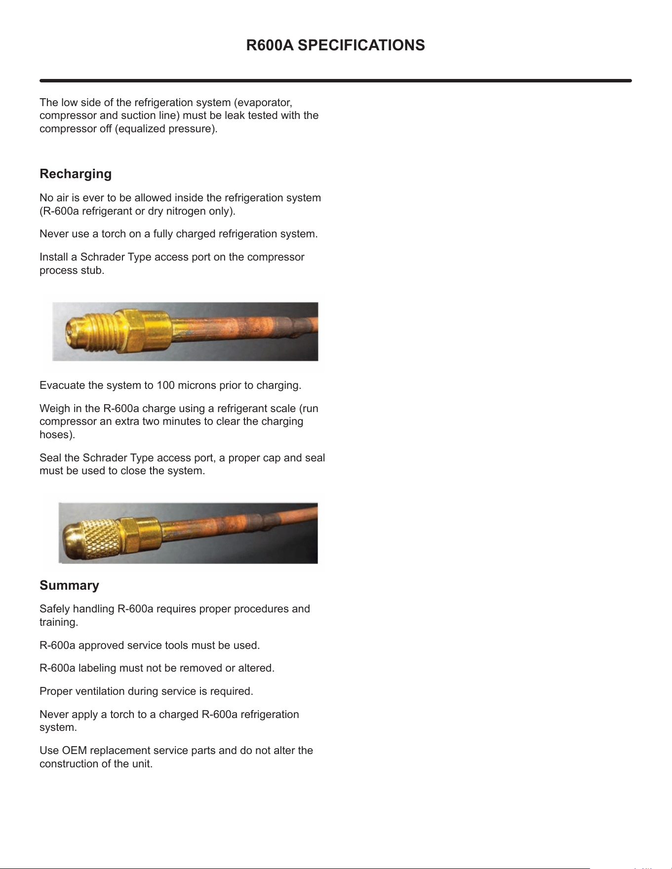
dry nitrogen or helium.
Electronic leak detection or soap solution can be used
tocheck for nitrogen/helium leaks.
Never use a halide torch or lighted match to check the
system for leaks at any time.
The high side of the refrigeration system (compressor
discharge to outlet of drier) must be leak tested with the
compressor running.
28
R600A SPECIFICATIONS
The low side of the refrigeration system (evaporator,
compressor and suction line) must be leak tested with the
compressor o (equalized pressure).
Recharging
No air is ever to be allowed inside the refrigeration system
(R-600a refrigerant or dry nitrogen only).
Never use a torch on a fully charged refrigeration system.
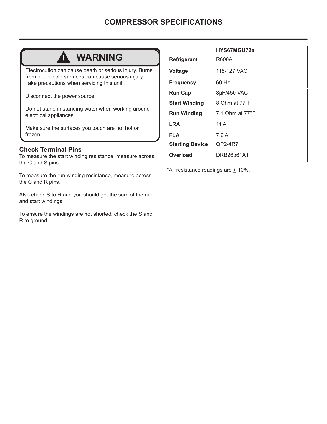
Install a Schrader Type access port on the compressor
process stub.
Evacuate the system to 100 microns prior to charging.
Weigh in the R-600a charge using a refrigerant scale (run
compressor an extra two minutes to clear the charging
hoses).
Seal the Schrader Type access port, a proper cap and seal
must be used to close the system.
S
ummary
Safely handling R-600a requires proper procedures and
training.
R-600a approved service tools must be used.
R-600a labeling must not be removed or altered.
Proper ventilation during service is required.
Never apply a torch to a charged R-600a refrigeration
system.
Use OEM replacement service parts and do not alter the
construction of the unit.
29
COMPRESSOR SPECIFICATIONS
!
WARNING
Electrocution can cause death or serious injury. Burns
from hot or cold surfaces can cause serious injury.
Take precautions when servicing this unit.
Disconnect the power source.
Do not stand in standing water when working around
electrical appliances.
Make sure the surfaces you touch are not hot or
frozen.
HYS67MGU72a
Refrigerant R600A
Voltage 115-127 VAC
Frequency 60 Hz
Run Cap 8µF/450 VAC
Start Winding 8 Ohm at 77°F
Run Winding 7.1 Ohm at 77°F
LRA 11 A
FLA 7.6 A
Starting Device QP2-4R7
Overload DRB26p61A1
*All resistance readings are + 10%.
Check Terminal Pins
To measure the start winding resistance, measure across
the C and S pins.
To measure the run winding resistance, measure across
the C and R pins.
Also check S to R and you should get the sum of the run
and start windings.
To ensure the windings are not shorted, check the S and
R to ground.
30
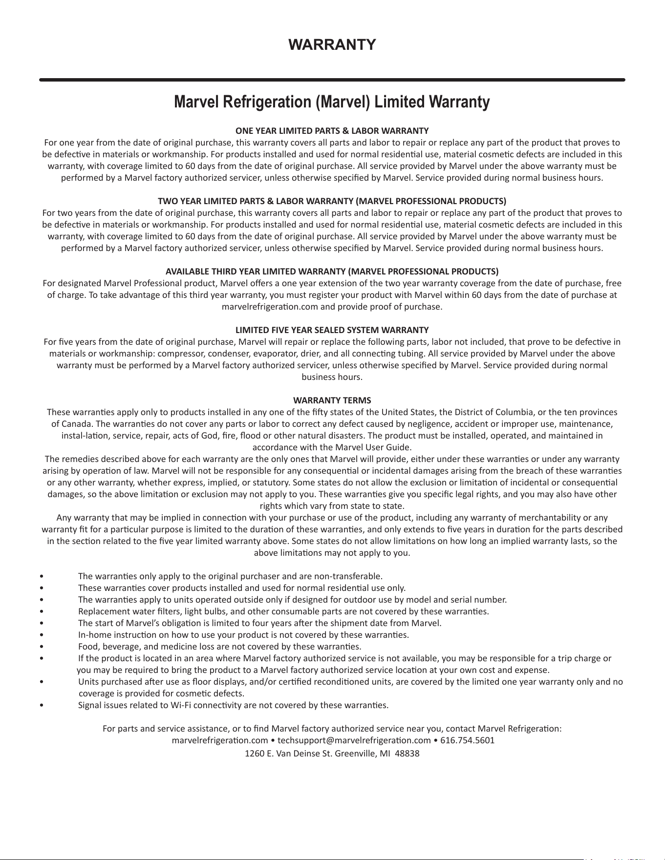
WARRANTY
ONE YEAR LIMITED PARTS & LABOR WARRANTY
For one year from the date of original purchase, this warranty covers all parts and labor to repair or replace any part of the product that proves to
be defecve in materials or workmanship. For products installed and used for normal residenal use, material cosmec defects are included in this
warranty, with coverage limited to 60 days from the date of original purchase. All service provided by Marvel under the above warranty must be
performed by a Marvel factory authorized servicer, unless otherwise specied by Marvel. Service provided during normal business hours.
TWO YEAR LIMITED PARTS & LABOR WARRANTY (MARVEL PROFESSIONAL PRODUCTS)
For two years from the date of original purchase, this warranty covers all parts and labor to repair or replace any part of the product that proves to
be defecve in materials or workmanship. For products installed and used for normal residenal use, material cosmec defects are included in this
warranty, with coverage limited to 60 days from the date of original purchase. All service provided by Marvel under the above warranty must be
performed by a Marvel factory authorized servicer, unless otherwise specied by Marvel. Service provided during normal business hours.
AVAILABLE THIRD YEAR LIMITED WARRANTY (MARVEL PROFESSIONAL PRODUCTS)
For designated Marvel Professional product, Marvel oers a one year extension of the two year warranty coverage from the date of purchase, free
of charge. To take advantage of this third year warranty, you must register your product with Marvel within 60 days from the date of purchase at
marvelrefrigeraon.com and provide proof of purchase.
LIMITED FIVE YEAR SEALED SYSTEM WARRANTY
For ve years from the date of original purchase, Marvel will repair or replace the following parts, labor not included, that prove to be defecve in
materials or workmanship: compressor, condenser, evaporator, drier, and all connecng tubing. All service provided by Marvel under the above
warranty must be performed by a Marvel factory authorized servicer, unless otherwise specied by Marvel. Service provided during normal
business hours.
WARRANTY TERMS
These warranes apply only to products installed in any one of the y states of the United States, the District of Columbia, or the ten provinces
of Canada. The warranes do not cover any parts or labor to correct any defect caused by negligence, accident or improper use, maintenance,
instal-laon, service, repair, acts of God, re, ood or other natural disasters. The product must be installed, operated, and maintained in
accordance with the Marvel User Guide.
The remedies described above for each warranty are the only ones that Marvel will provide, either under these warranes or under any warranty
arising by operaon of law. Marvel will not be responsible for any consequenal or incidental damages arising from the breach of these warranes
or any other warranty, whether express, implied, or statutory. Some states do not allow the exclusion or limitaon of incidental or consequenal
damages, so the above limitaon or exclusion may not apply to you. These warranes give you specic legal rights, and you may also have other
rights which vary from state to state.
Any warranty that may be implied in connecon with your purchase or use of the product, including any warranty of merchantability or any
warranty t for a parcular purpose is limited to the duraon of these warranes, and only extends to ve years in duraon for the parts described
in the secon related to the ve year limited warranty above. Some states do not allow limitaons on how long an implied warranty lasts, so the
above limitaons may not apply to you.
• The warranes only apply to the original purchaser and are non-transferable.
• These warranes cover products installed and used for normal residenal use only.
• The warranes apply to units operated outside only if designed for outdoor use by model and serial number.
• Replacement water lters, light bulbs, and other consumable parts are not covered by these warranes.
• The start of Marvel’s obligaon is limited to four years aer the shipment date from Marvel.
• In-home instrucon on how to use your product is not covered by these warranes.
• Food, beverage, and medicine loss are not covered by these warranes.
• If the product is located in an area where Marvel factory authorized service is not available, you may be responsible for a trip charge or
you may be required to bring the product to a Marvel factory authorized service locaon at your own cost and expense.
• Units purchased aer use as oor displays, and/or cered recondioned units, are covered by the limited one year warranty only and no
coverage is provided for cosmec defects.
• Signal issues related to Wi-Fi connecvity are not covered by these warranes.
For parts and service assistance, or to nd Marvel factory authorized service near you, contact Marvel Refrigeraon:
marvelrefrigeraon.com • techsupport@marvelrefrigeraon.com • 616.754.5601
1260 E. Van Deinse St. Greenville, MI 48838
Marvel Refrigeration (Marvel) Limited Warranty
31
Marvel Refrigeration
All specications and product designs subject to change without notice. Such revisions do not entitle
the buyer to corresponding changes, improvements, additions, replacements or compensation for
previously purchased products.
www.marvelrefrigeration.com
1260 E. Van Deinse St.
Greenville MI 48838
616.754.5601
32