
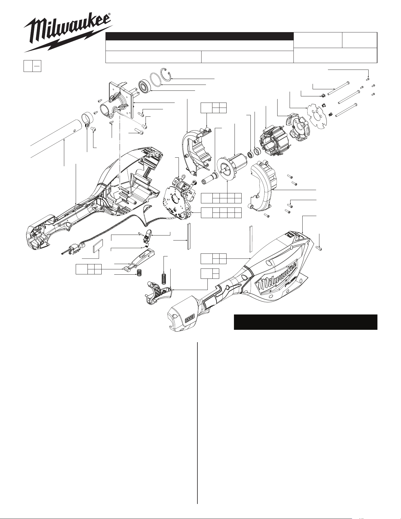
M18™ FUEL™ SHORT POLE HEDGE TRIMMER
3043-20
P71A
54-49-2885
See Page 5
Oct. 2024
REVISED BULLETIN
SERVICE PARTS LIST
BULLETIN NO.
WIRING INSTRUCTION
DATE
SPECIFY CATALOG NO. AND SERIAL NO. WHEN ORDERING PARTS
CATALOG NO.
STARTING
SERIAL NO.
EXAMPLE:
Component Parts (Small #)
Are Included When Ordering
The Assembly (Large #).
0
00
FIG. PART NO. DESCRIPTION OF PART NO. REQ.
3 --------------- O-Ring (1)
4 --------------- Internal Retaining Ring (1)
5 --------------- Deep Groove Ball Bearing (1)
6 --------------- Motor Mount (1)
7 --------------- Drive Shaft Coupling (1)
8 --------------- Deep Groove Ball Bearing (1)
9 22-32-0102 Rubber Cap (1)
10 --------------- Rotor (1)
17 --------------- PCB Assembly (1)
18 --------------- Silicone Isolator (3)
20 --------------- Heatsink Cap (1)
21 05-81-0089 M2.5 x 6mm Pan Hd. T-8 Machine Screw (4)
23 --------------- Stator (1)
24 05-88-5375 M4 x 13.5mm Pan Hd. ST T-20 Screw (14)
25 05-78-0029 M5 x 8mm Pan Hd. T-25 Machine Screw (2)
26 05-78-0033 M5 x 20mm Pan Hd. T-25 Machine Screw (1)
27 05-81-1195 M3 x 8mm Pan Hd. ST T-10 Screw (3)
28 --------------- M3 x 12mm Pan Hd. Tapt. T-10 Screw (5)
29 --------------- Motor Housing Cover (1)
30 --------------- Motor Housing Support (1)
31 --------------- Power Head Housing Cover (1)
32 --------------- Power Head Housing Support (1)
33 45-72-8453 Trigger (1)
34 44-52-0001 Rubber Damping Bar (2)
35 05-74-0516 M4 x 67mm Pan Hd. T-20 Machine Screw (3)
MILWAUKEE TOOL
l
www.milwaukeetool.com
13135 W. Lisbon Road, Brookeld, WI 53005
Drwg. 1
FIG. PART NO. DESCRIPTION OF PART NO. REQ.
36 40-50-0254 Lock O Spring (1)
37 40-50-0374 Trigger Spring (1)
38 --------------- Lock O Toggle (1)
39 23-66-0236 Release Trigger (1)
40 --------------- Toggle Spring (1)
41 44-60-0213 Rivot Pin (1)
42 --------------- Tube Clamp (1)
43 --------------- Heat Insulator (1)
79 --------------- Tube (1)
80 --------------- Foam Rubber Block (1)
100 14-20-0789 Stator/PCBA Service Assembly (1)
101 16-01-6138 Rotor Service Assembly (1)
105 14-34-8117 Power Head Service Kit (1)
106 31-01-7422 Volute Service Kit (1)
108 14-46-6762 Activation Trigger Service Kit (1)
109 45-72-0037 Lock O Trigger Service Kit (1)
12-20-0374 Service Nameplate (Not Shown) (1)
80
21
(4x)
35
(3x)
18
(3x)
43
20
23
9
8
10
30
7
32
17
4
3
5
6
24
25
26
27
(3x)
25
42
79
29
28
(5x)
31
24
(14x)
41
40
39
36
38
34
(2x)
37
33
17 18 20 21
23 35 43
100
3 4 5 6
7 8 9 10
101
105
24 31
32 34
108
33
37
106
27 28
29 30
109
38 39
40 41
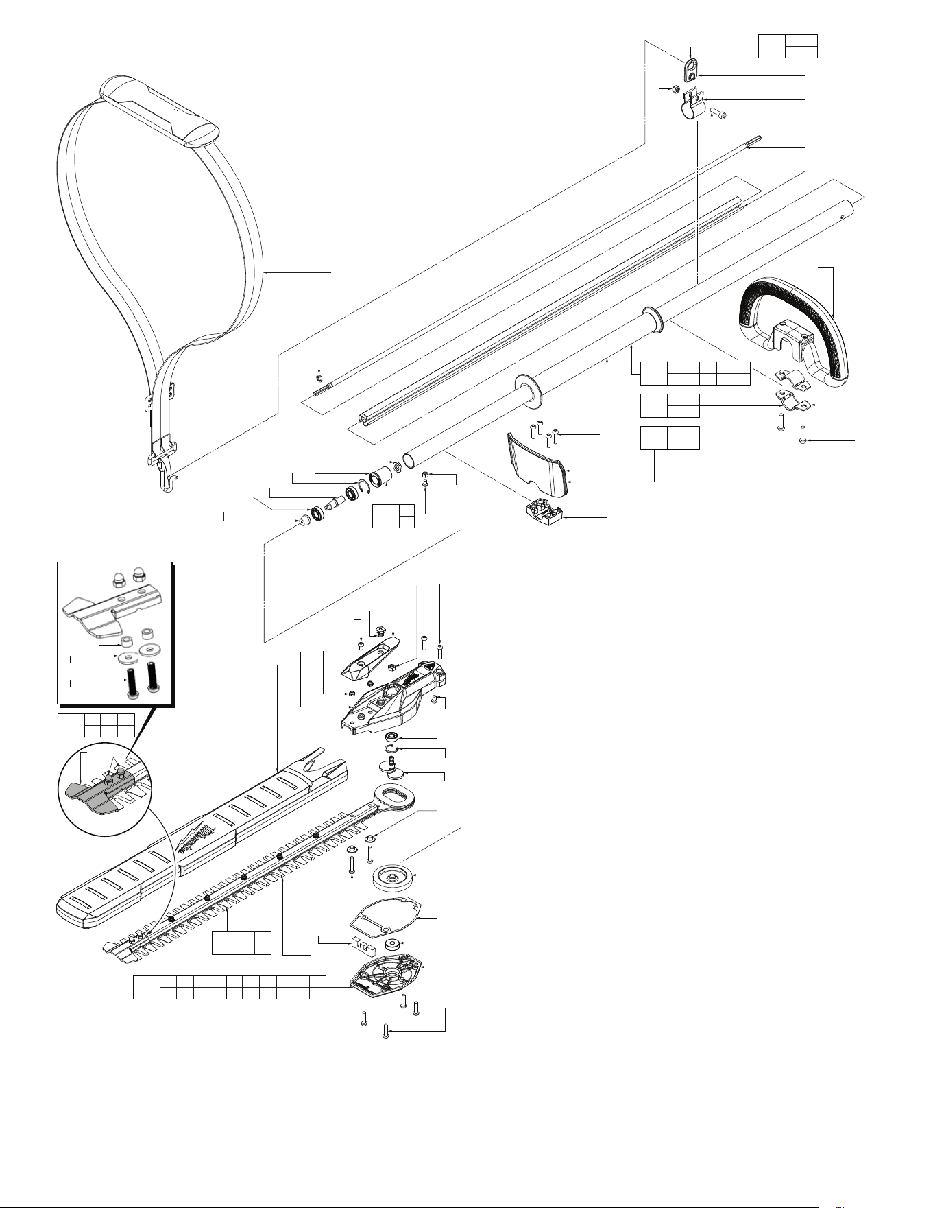
SEE PAGE 3 FOR SCREW TORQUE SPECIFICATIONS
SEE PAGE 4 FOR RECOMMENDED FASTENING ORDER
56
57
(2x)
52
51
69
71
26
(2x)
61
50
44
25
46
(2x)
60
47
25
62
63
65
67
(2x)
64
54
58
59
26
(4x)
66
(2x)
53
68
79
26
(4x)
49
48
76
75
74
72
73
78
61
1
(2x)
2
(2x)
77
70
25 26 44 46 50 51 52 53 54 56
57 58 59 60 61 62 63 64 65
102
86
87
104
46 66
67 68
107
61 74
75 76
110
69
71
111
1 2
78
112
26 48
49 92
113
81 82 83
84 85
82 81
103
45 70 72 73 79
86 87 90 91 93
103
83(2x)
84(2x)
85(2x)
FIG. PART NO. DESCRIPTION OF PART NO. REQ.
1 28-28-0053 Bail Handle Plate (2)
2 05-74-0242 M6 x 25mm Pan Hd. T-30 Machine Screw (2)
25 05-78-0029 M5 x 8mm Pan Hd. T-25 Machine Screw (2)
26 05-78-0033 M5 x 20mm Pan Hd. T-25 Machine Screw (10)
44 05-85-0080 M8 x 8mm Hex Hd. T-25 Machine Screw (1)
45 44-22-0050 277 Red Loctite (1)
46 05-55-0019 Hex Nut (2)
47 49-62-0018 Blade Sheath (1)
FIG. PART NO. DESCRIPTION OF PART NO. REQ.
48 --------------- Hand Guard Bottom Clamp (1)
49 --------------- Hand Guard (1)
50 28-20-0108 Gearcase Cover (1)
51 --------------- Bevel Internal Retaining Ring (1)
52 --------------- 6T Splined Coupler (1)
53 45-06-0108 Felt Seal (1)
54 43-44-0048 Gearcase Gasket (1)
56 --------------- Bevel Pinion (1)
57 --------------- Ball Bearing (2)
58 --------------- Ball Bearing (1)
59 --------------- Bottom Gearcase Housing (1)
60 --------------- Top Gearcase Housing (1)
61 06-57-0625 Nylon Insert Lock Nut (2)
62 --------------- Ball Bearing (1)
63 31-86-0045 Bevel C-Ring (1)
64 32-05-0042 Bevel Gear (1)
65 36-17-0022 Crank Shaft (1)
66 05-78-0019 M5 x 25mm Pan Hd. T-25 Machine Screw (2)
67 42-40-0123 Bushing (2)
68 --------------- Blade Assembly (1)
69 --------------- Retaining Sleeve (1)
70 --------------- E-Ring (1)
71 45-88-0885 Flat Washer (1)
72 --------------- Drive Shaft (1)
73 --------------- Extruded Sleeve (1)
74 05-74-0015 M6 x 21.5mm Cap Hd. T-30 Machine Screw (1)
75 45-56-0011 Shoulder Strap Mounting Band (1)
76 44-66-0039 Shoulder Strap Mounting Plate (1)
77 43-74-0116 Shoulder Strap (1)
78 31-44-0408 Bail Handle (1)
79 --------------- Hedge Trimmer Tube (1)
81 05-59-8571 M5 Accorn Nut (2)
82 --------------- Blade Tip Guard (1)
83 42-40-6478 Bushing (2)
84 45-88-1457 Flat Washer (2)
85 45-04-9155 M5 x 21mm Pan Hd. T-25 Screw (2)
86 --------------- M4 Hex Nut (1)
87 --------------- M4 x 6mm Pan Hd. T-20 Machine Screw (1)
102 14-30-6407 Gearcase Service Kit (1)
103 14-73-5574 Drive Shaft Service Assembly (1)
104 42-26-5271 Blade Service Kit (1)
107 43-74-3315 Harness Hook Service Kit (1)
110 14-75-0661 Retaining Sleeve Service Assembly (1)
111 14-34-8122 Bail Handle Service Kit (1)
112 43-54-1741 Hand Guard Service Kit (1)
113 14-46-6784 Blade Tip Service Kit (1)
FIG. PART NO. DESCRIPTION OF PART NO. REQ.
90 10-22-1027 Tri-lingual Warning Label (Not Shown)
Located on Tube (1)
91 10-22-1028 Bi-lingual Warning Label (Not Shown)
Located on Tube (1)
92 10-22-1029 Multi-Symbol Warning Label (Not Shown)
Located on Hand Guard (1)
93 --------------- 'Place Handle Here' Label (Not Shown)
Located on Tube (1)
SCREW TORQUE SPECIFICATIONS
SEAT TORQUE
FIG. PART NO. DESCRIPTION OF FASTENER WHERE USED (lb-in) (kgf-cm)
2 05-74-0242 M6 x 25mm Pan Hd. T-30 Machine Screw Bail Handle Plate / Bail Handle 21-24 25-28
21 05-81-0089 M2.5 x 6mm Pan Hd. T-8 Machine Screw Heat Sink Cap / Heat Sink Insulator 3.9-4.7 4.5-5.5
24 05-88-5375 M4 x 13.5mm Pan Hd. ST T-20 Screw Motor Mount 6.9-8.6 8-10
24 05-88-5375 M4 x 13.5mm Pan Hd. ST T-20 Screw Power Head Housing Cover 7.7-9.5 9-11
25 05-78-0029 M5 x 8mm Pan Hd. T-25 Machine Screw Gearcase Cover 23-28 27-33
25 05-78-0029 M5 x 8mm Pan Hd. T-25 Machine Screw Gearcase Top Housing 23-28 27-33
25 05-78-0029 M5 x 8mm Pan Hd. T-25 Machine Screw Tube Clamp 20-22 24-26
25 05-78-0029 M5 x 8mm Pan Hd. T-25 Machine Screw Motor Mount 20-22 24-26
26 05-78-0033 M5 x 20mm Pan Hd. T-25 Machine Screw Gearcase Top Housing 27-33 32-38
26 05-78-0033 M5 x 20mm Pan Hd. T-25 Machine Screw Gearcase Bottom Housing 23-28 27-33
26 05-78-0033 M5 x 20mm Pan Hd. T-25 Machine Screw Bottom Guard Clamp 12.9-17.2 14-18
26 05-78-0033 M5 x 20mm Pan Hd. T-25 Machine Screw Motor Mount 20-22 24-26
27 05-81-1195 M3 x 8mm Pan Hd. ST T-10 Screw Motor Mount 2.5-3 2.9-3.5
28 --------------- M3 x 12mm Pan Hd. Tapt. T-10 Screw Motor Housing Cover 3.4-5.2 4-6
35 05-74-0516 M4 x 67mm Pan Hd. T-20 Machine Screw Stator Assembly 22.4-25.8 26-30
44 05-85-0080 M8 x 8mm Hex Hd. T-25 Machine Screw Gearcase Cover 23-28 27-33
61 06-57-0625 Nylon Insert Lock Nut Gearcase Cover 26-30 30-35
66 05-78-0019 M5 x 25mm Pan Hd. T-25 Machine Screw Bushing / Blade Assembly 47-56 55-65
74 05-74-0015 M6 x 21.5mm Cap Hd. T-30 Machine Screw Shoulder Strap Mounting Band 21-24 25-28
81 05-59-8571 M5 Accorn Nut Blade Tip Guard 31-35 44-51
85 45-04-9155 M5 x 21mm Pan Hd. T-25 Screw Blade Tip Guard 31-35 44-51
87 --------------- M4 x 6mm Pan Hd. T-20 Machine Screw Tube 8.6-12.9 10-15
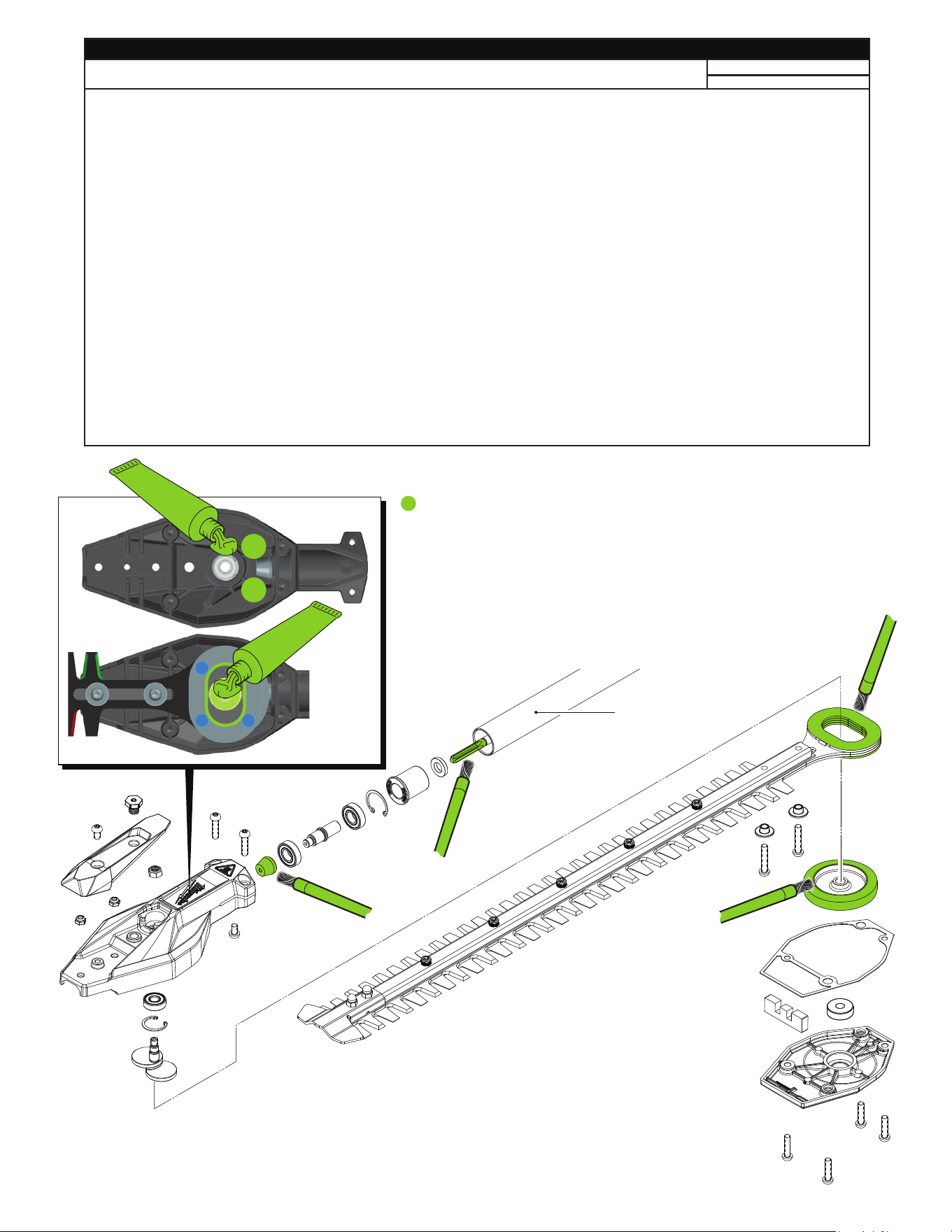
LUBRICATION NOTES:
Type ‘J’ Grease, No. 49-08-4220 1 lb. can
Type ‘J’ Grease, No. 49-08-2010 7-1/2 1 lb. can
NOTE: When servicing, remove 90-95% of the existing grease prior to installing
Type ‘J’. Original grease may be similar in color but not compatible with ‘J’.
Prior to reinstalling, clean gear assemblies with a clean, dry cloth.
Lightly coat all individual parts highlighted here with grease.
Apply a greater amount of grease to all internal and external gear teeth.
Place approx. 15 g
grease here
Place
approx.
3g grease
in groove
as shown
Inside of
Drive Shaft Assembly
is pre lubricated

Step 6
Screws #26
Step 5
Screws #25 and #44
Step 4
Screws #26
Step 3
Screws #66
Step 2
Screws #24
Step 1
Screws #21
Step 7
Screws #35
Step 8
Screws #27
Step 9
Screws #28
RECOMMENDED TIGHTENING STEPS AND
SEQUENCES FOR FASTENERS.
SEE PAGE 3 FOR TORQUE SPECIFICATIONS.
14
13
12
11
4
8
9
3
10
1
2
5
6
7
1
2
3
4
1
2
1
2
3
4
1
2
1
2
3
4
1
2
3
1
2
3
1
2
3
4
5
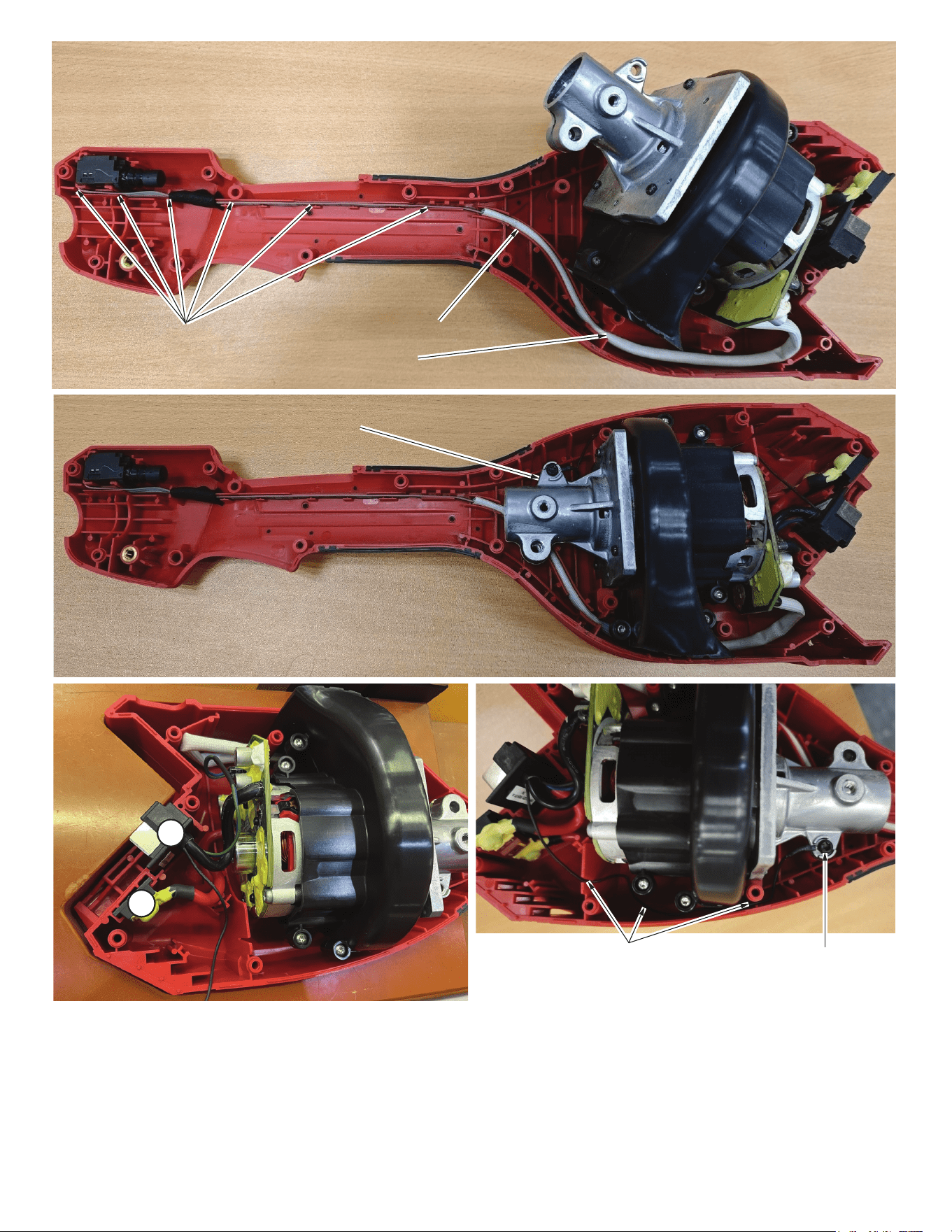
Install switch and switch wireswires as shown, removing any excess slack while
routing. Be sure to tuck wires completely down in wire traps and wire channels.
Wire traps
Wire channel
Wire trap
Install motor mount / motor housing over the trapped wires.
Secure motor mount and motor housing with screws.
1. Place Fuse in slot first
2. Install Battery Terminal Block second
As an aid to reassembly, take notice of wire routings and position in wire guides, wire
channels and wire traps while dismantling tool.
Be sure that all components of the electronics assembly are seated firmly and squarely in
housing recesses.
Avoid pinched wires, be sure that all wires and wire sleeves are pressed completely down in
wire channels and wire traps.
Prior to securing power head housing halves together be sure that there are no interferences.
Before installing the battery, check for proper functionality of shuttles, buttons and triggers.
Route ground wire as shown, placing
wire completely down in wire traps.
Ground wire terminal
1
2