
Technical Support and E-Warranty Certificate
www.vevor.com/support
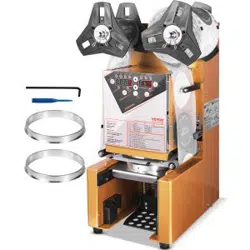
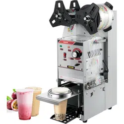
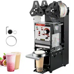
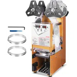
SEALING MACHINE
We continue to be committed to provide you tools with competitive price.
"Save Half", "Half Price" or any other similar expressions used by us only represents an
estimate of savings you might benefit from buying certain tools with us compared to the major
top brands and does not necessarily mean to cover all categories of tools offered by us. You
are kindly reminded to verify carefully when you are placing an order with us if you are
actually saving half in comparison with the top major brands.

- 1 -
WY-890 WY-980
Have product questions? Need technical support? Please feel free to
contact us:
Technical Support and E-Warranty Certificate
www.vevor.com/support
NEED HELP? CONTACT US!
This is the original instruction, please read all manual instructions
carefully before operating. VEVOR reserves a clear interpretation of our
user manual. The appearance of the product shall be subject to the
product you received. Please forgive us that we won't inform you again if
there are any technology or software updates on our product.
SEALING MACHINE
- 2 -
1. Important safety instructions
This instruction manual is intended for your benefit. Please read and follow
the safety, installation, maintenance and troubleshooting steps described
within to ensure your safety and satisfaction.
The contents of this instruction manual are based on the latest product
information available at the time of publication. The manufacturer reserves
the right to make product changes at any time without notice.
Always use common sense and pay particular attention to all the DANGER,
WARNING, CAUTION and NOTICE statements in this manual.
Maintain labels. These carry important information. The label on your tool may
include the following symbols. The symbols and their definitions are as follows:
Warning - To reduce the risk of injury, user must read instructions
manual carefully.
Alternating current
This symbol, placed before a safety comment, indicates a kind of
precaution, warning, or danger. Ignoring this warning may lead to
an accident. To reduce the risk of injury, fire, or electrocution,
please always follow the recommendations shown below.
Danger!
Risk of personal injury or environmental damage! Risk of electric
shock! Risk of personal injury by electric shock!
Disposal information:
This product is subject to the provision of European Directive
2012/19/EC. The symbol showing a wheelie bin crossed through
indicates that the product requires separate refuse collection in the
European Union. This applies to the product and all accessories
marked with this symbol. Products marked as such may not be
discarded with normal domestic waste, but must be taken to a
collection point for recycling electrical and electronic devices

- 3 -
This device complies with Part 15 of the FCC Rules. Operation is
subject to the following two conditions:(1)This device may not
cause harmful interference, and (2)this device must accept any
interference received, including interference that may cause
undesired operation.
WARNING
Prior to using this product, please read and understand all instructions and
safety warnings. Improper use may result in serious injury or property damage.
1.Warnings must be followed carefully to avoid body injury. Improper use may
result in electric shock, fire, personal injury and other damage:
1)Keep unplugging when moving the machine.
2)Keep unplugging when installing accessories.
3)Place on a flat and stable platform.
4)Do not use this machine in a hazardous-location.
5)Do not use when the machine is not working properly.
6)Do not disassemble and repair this machine.
7)Do not use an unsuitable AC Outlet.
8)Do not touch the heating plate when the machine is working .
9)Do not use it in a humid environment or contact with water Do not infiltrate
liquid in the machine to prevent fire or electric shock caused by short circuit.
10)Do not use the power supply that does not meet the rated voltage. The power
supply that does not meet the specified voltage may cause fire or electric shock.
11)Ensure that the machine is grounded so as not to cause harm to the body.
12)Do not touch the moving part with your fingers during use in case of injuries.

- 4 -
13)If the machine is not in use for a long time, please unplug the power cord from
the socket.
14)Please stop using it if the machine smokes, emits a peculiar smell, or
becomes noisy and in other abnormal conditions.
15)if they have been given supervision or instruction concerning use of the
appliance in a safe way and understand the hazards involved. Children shall not
play with the appliance. Cleaning and user maintenance shall not be made by
children without supervision
16)Type Z attachment: If the supply cord cannot be replaced. If the cord is
damaged the appliance should be scrapped.
17)In order to avoid a hazard due to inadvertent resetting of the thermal cutout,
this appliance must not be supplied through an external switching device, such
as a timer, or connected to a circuit that is regularly switched on and off by the
utility.
18)Operating and fixing of this product must be conducted by qualified person.
19)Please install this machine according to our instructions.
20)Once unpack the machine, check it throughout to make sure it is complete.
21)Once unpack the machine, check it throughout to make sure it is complete.
22)Any missing or damage please consult it before operating.
23)The packing material should be placed beyond the reach of children.
24)Please turn off the machine when the operator is absent.If you need a repair,
please ask for an expert and use the original spare part.
25)Do not rinse the machine with water directly.
26 ) Clean the surface of stainless steel periodically in appropriate method to
prevent any damages brought by oxidization or chemical interference.

- 5 -
FCC INFORMATION
CAUTION: Changes or modifications not expressly approved by the
party responsible for compliance could void the user's authority to operate
the equipment!
This device complies with Part 15 of the FCC Rules. Operation is subject
to the following two conditions:
1) This product may cause harmful interference.
2)This product must accept any interference received, including
interference that may cause undesired operation.
WARNING: Changes or modifications to this product not expressly
approved by the party.responsible for compliance could void the user's
authority to operate the product.
Note: This product has been tested and found to comply with the limits
for a Class B digital device pursuant to Part 15 of the FCC Rules, These
limits are designed to provide reasonable protection against harmful
interference in a residential installation.
This product generates, uses and can radiate radio frequency energy, and
if not installed and used in accordance with the instructions, may cause
harmful interference to radio communications. However, there is no
guarantee that interference will not occur in a particular installation. If this
product does cause harmful interference to radio or television
reception,which can be determined by turning the product off and on, the
user is encouraged to try to correct the interference by one or more of the
following measures.
· Reorient or relocate the receiving antenna.
· Increase the distance between the product and receiver.
· Connect the product to an outlet on a circuit different from that to which
the receiver is connected.
· Consult the dealer or an experienced radio/TV technician for assistance.
- 6 -
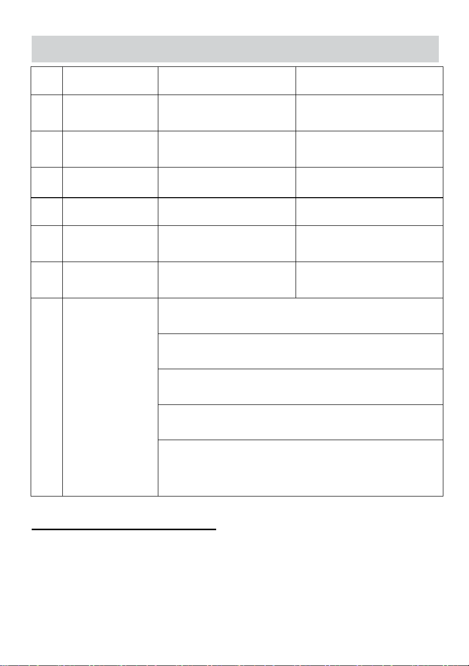
PARAMETER
Item
Description
WY-890
WY-980
1
Rated Voltage:
AC110V~120V 60Hz( For
US user)
AC110V~120V 60Hz( For US
user)
2
Rated Voltage:
AC220~240V 50Hz( For
Europe user)
AC220~240V 50Hz( For
Europe user)
3
Rated Power:
350W
350W
4
Out Put
500-650 cups/h
500-650 cups/h
5
Sealing Diameter
90mm / 95mm
90mm / 95mm
6
Maximum Cup
Height
180mm
190mm
7
Cup sealing
parameters
Material: PS; Cup sealing temperature range: 160°C to
190°C;
Material: PE; Cup sealing temperature range: 160°C to
190°C;
Material: PP; Cup sealing temperature range: 160°C to
210°C;
170°c has been highlighted on the label to allow users to
quickly select
Note:Cups made of other materials may not be suitable for
this device. Please refer to the cup manufacturer's
recommended usage methods to seal the cup before use.
Transportation and storage:
Please handle the appliance with care and avoid any violent vibration, collision or
inversion. Storage The places for storage should have good ventilation and no
corrosive gas. Long-time Open-air storage is not encouraged, if it is inevitable,
measures should be taken to protect the machine from rain and blazing sun.
- 7 -
Installation:
1) Voltage
The actual voltage should be the same as or within the range of 10% on either side
of voltage marked on the parameter sticker.
2) Install sets
The appliance should be placed with power switch(10A)and leakage
protector(S30mA) equipped around, and with no stuff around to hinder the
operation.
3) Check
Please check carefully whether spare parts are fasten, the power wire is firmly
fixed and the electric connection is in good condition.
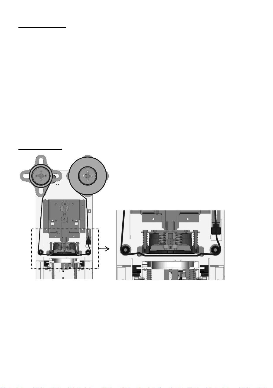
Preparation
Film Installation diagram
1.According to the above installation diagram to place the film. Please take care of
the positive and negative sides of film, The negative side should be forwarded to
the lip of cup. Otherwise, the film will fail to seal the cup.
2. Plug in the machine and turn on the switch of power, lower mould will sent
autocratically in the meantime. The heating lamp will be flashed which means the
heating tube is working.

- 8 -
3. About 5 minutes later, when the lamp keeps on, it means the setting
temperature was reached and automatic sealing operation can be performed. Only
can use it by manual sealing operation if the setting temperature is not reached.
4. Selection of cup and sealing film
a. Easy ripping film is suitable for sealing the cup of a variety of materials.
b. In other cases, the materials of cup must be same as the film. Such as the
cup of PP (Polypropylene) must be used with the film of PP.
c. the recommended temperature refers to the Parameter form.
5.Switch off the power after finishing the sealing, and the lower mould will go in
automatically, then take the plug out.
6. In case there is an accident, never put your hand into the machine when it is
working.
Usage instructions
Begin sealing the cup when completing above preparation:
1.Press the button of auto operation, light is on.
2.Put the cup filled liquid into the down plate, then it is sent into the machine by
pulling-plate. Do not seal empty cup for testing cause the light cup will be
adsorbed on the heating plate and stick the film.
3.The machine will automatically roll the firm, seal the cup, cut the film and output
the cup plate, and then the counter displayer will count the quantity.
4.Take out the cup and finish one operation.
Please confirm that the space between two color patches of the film is no
less than 115 mm.
Attention
1.In order to protect the electric system of the machine, don't rinse it by water;
only clean it with cloth and cleaning liquid which contains no corrosive
components.
2. Please turn off the machine when the operator is absent .
3.In case there is a short circuit or fault, please plug off the machine and request
qualified people to repair it.
4. In case of repair, please ask for an expert and use the original spare part.
- 9 -
Cleaning and maintaining
1.Please check carefully whether the upper mould is clean every day, to prevent
the foreign substance from sticking to the mould cause a failure to seal the cup.
2. Please use dry cloth to clean the surface of machine, bottom of plate and put
grease on the
bearings and moving parts of the machine to make it work more easily.
3. Clean the grooved plate and pulling plate to avoid the damage of upper cutter.
4. Keep the cleanness of electric eye, to avoid the foreign substances interfering
the detection of the film cause disoperation.
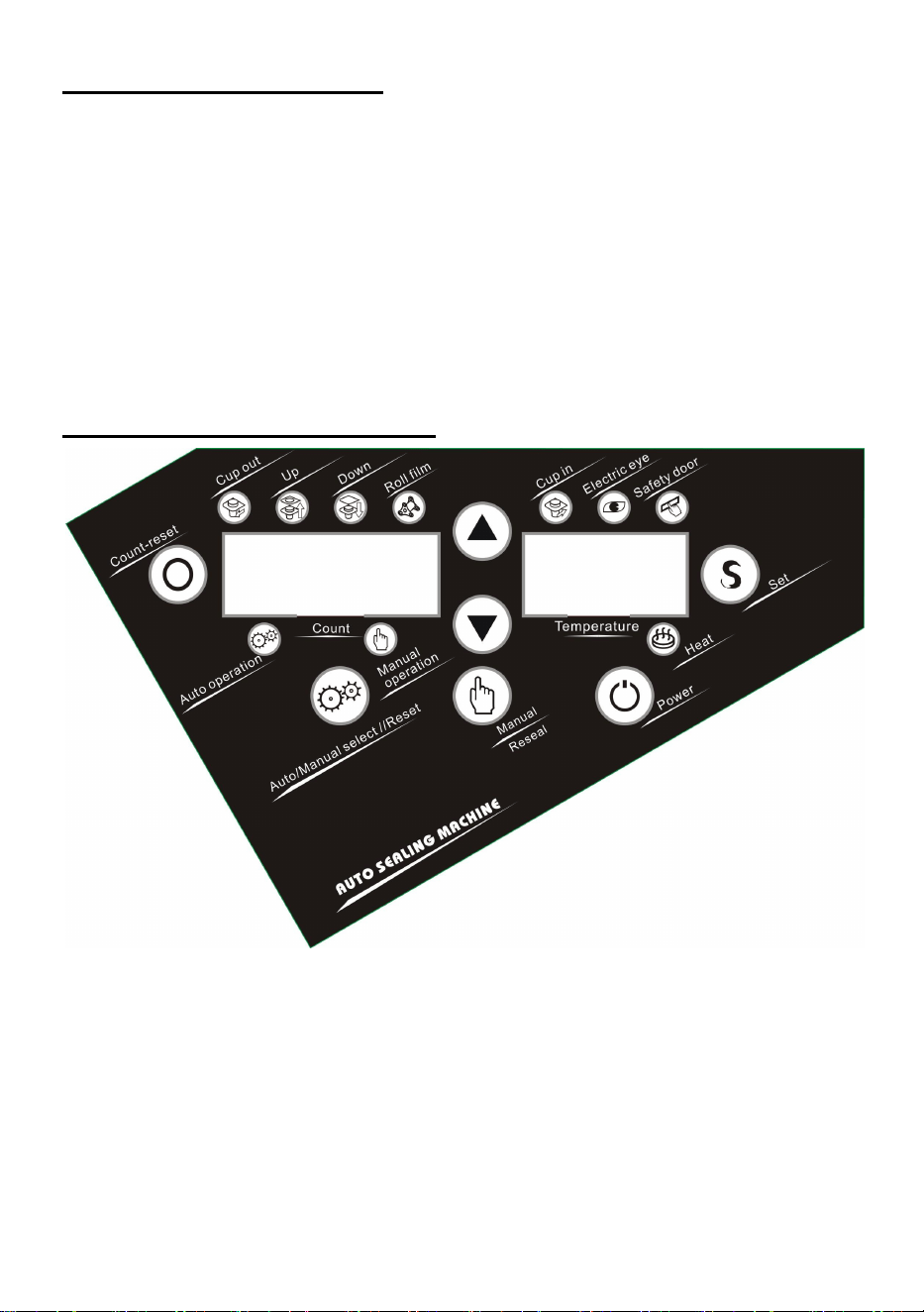
Introductions of control panel
1.Power button please press this button while using it, the screen will display and
lower mould will be sent out, which means the machine enters the standby state.
2.Auto/Manual select//Reset button:
a .When the automatic light is on which means the machine got into the state of
automatic. After setting the cup, it will send the cup in and complete the whole
sealing operation automatically (temperature must be reached to the setting point
and the heating lamp keeps on.)

- 10 -
b. When the automatic light is on which means the machine gets into the state of
automatic. If you press the button of reseal, the machine will get into the state of
resealing. The LED light of counting will flash, then press the button of manual, the
machine will seal.
c. When the manual light is on which means the machine gets into the state of
manual. After the cup is put in, then press the button of manual, the machine will
seal (without temperature limit).
3.Set button: Setting or changing the faction of machine Up or down buttons:
Choosing the function of computer to increase or decrease the quantity.
Count-reset button: Cleaning out the records of sealing quantity and reset to zero.
4.Count display:
a. Display the quantity of sealing cups in normal condition
5.Temperature display
a. Display the temperature of heating plate in normal conditions.
b. Display the setting point in setting state.
c. Display the fault code while fault occurs.
6.Safety door: When the light is on which means the exit was touched.
7.Electric eye: It indicates that electric eye has detected black spot in the film
when the light is on.
8.Cup in: The cup entering into the machine when the light is on.
9.Roll film: The machine rolls the film when the light is on.
10.Down: The upper mould pressing and sealing the cup.
11.Up: The upper mould rising and resetting.
12.Cup out: The cup is coming out from the machine
13.Automatic operation: The machine gets into the state of automatic.
14.Manual operation: The machine gets into the state of manual.
15.Heat:The heating lamp will flash when the heating tube is working; And when
the lamp keeps on, it means the setting temperature was reached.

- 11 -
Computer setup
Computer function set project:
Items
Function set
Range
Default setting
P1
temperature
PP(160~190℃)
(easy ripping film
120~180℃)
170℃
P2
counting Lock
0:lock1:unlock
000(Lock,can't be reset)
P3
length of
cup-sending
time
001~003(1s~3s)
001(1s)
P4
Length of
sealing time
001~005(1s~5s)
001(1s)
P5
Length of rolling
time
000~006(1s~6s)
000(controlled by electronic eye)
Setup Method:
1.Press the "S" key for the first time to get into the state of temperature
setting: Left shows [00P1 ],Right shows [180 ], choosing the up or down key can
adjust the range of temperature.
2.Press the"S" key for the second time to get into the state of counting lock:
Left shows [00P2 ],Right shows [000 ](Lock), choosing the up or down key can
change to [001 ](Unlock).
3.Press the "S"key for the third time to get into the state of cup-in time setting:
Left shows [00P3 ],Right shows [001 ] for 1 second, choosing the up or down key
can adjust the range of time [001 ~003] for 1~3 seconds.
4.Press the "S" key for the fourth time to get into the state of sealing time
setting: Left shows [00P4 ],Right shows [001 ] for 1 second, choosing the up or
down key can adjust the range of time [001 ~005] for 1~5 seconds.
5.Press the "S"key for the fifth time to get into the state of rolling time setting:
Left shows [00P5],Right shows [000 ] which control by electric eye, choosing the
up or down key can adjust the range of time [001 ~006] for 1~6 seconds..
6.Press the "S"key for sixth time to save all the settle of previous, the machine will
go back to standby state and display the real quantity and temperature.
- 12 -
Code transaction
Fault Code:
This machine was equipped with auto-detect function, the system automatically
asks the fault code and alarm when it is out of order.
Number
Code
Error Situation
1
OE1
Failure of cup in(Micro Switch).
2
OE2
The safety door is touched.
3
OE3
The film is unplaced or electric eye can't detect the black spot
of the film
4
OE4
Failure of down(Micro Switch)
5
OE5
Failure of up(Micro Switch).
6
OE6
Failure of temperature detector
7
OE7
Failure of heater or connect wire
8
OE8
Failure of cup out(Micro Switch).
Fault code elimination method:
OE1:Error of Cup In
1.Micro switch with bad contacts: Change a new Micro switch.
2.Micro switch with the poor contact of connection: Reconnect it.
3.The screw of micro switch has got loose: Tighten the screw.
4.The screw of swing link has got loose cause of skidding:
Tighten the screw.5.The motor of cup in doesn't work, check the wire and
tighten the wire when it's loose.6.The motor of cup in doesn't work, change the
motor
7.Guide rails enclosed foreign matter, please clean the matter.

- 13 -
OE2 Error of Safety Door
1.The safety door is stuck with the micro switch: Adjust the safety door
2.Failure of micro switch: Change the micro switch.
OE3 Error of Rolling Firm
1.Electric eye with bad reaction:
a. please clean the foreign matter if there are.
b. Adjust the sensitivity adjustment of electric eye to ensure that the light will be
on when the black spot pass.
c. None of them is right, please change the electric eye
2.The firm is installation errors and not placed in the notch: Adjust its setting
position.
3.The film can't move:
a. The motor of film is running, but the film keeps the
same. and the paper cylinder and plastic splint is slipping, please reset the
Paper cylinder and plastic splint.
b. When the motor doesn't work, check the wire is loose or
not. If the connection of wire is right, please change a new motor
OE4 Error of Down
1.The damage of micro switch, change a new one.
2.Micro switch with the poor contact of connection: Reconnect it.
3.The screw of micro switch has got loose: Tighten the screw
OE5 Error of Up
1.The damage of upper micro switch, change a new one.
2.Micro switch with the poor contact of connection: Reconnect it.
3.The screw of micro switch has got loose: Tighten the screw

- 14 -
OE6 Error of Temperature detector
1.Temperature detector with the poor contact of connection: Reconnect it.
2.Thermal line is disconnection: Change it.
3.The issue of circuit board,change it.
OE7 Error of heating
1.The damage of heating plate: change the heating plate
2.Heating plate with the poor contact of connection: Reconnect it.
3.The issue of circuit board, change it.
OE8 Error of Cup Out
1.Micro switch with bad contacts: Change a new Micro switch.
2.Micro switch with the poor contact of connection: Reconnect it.
3.The screw of micro switch has got loose: Tighten the screw.
4.The screw of swing link has got loose cause of skidding:
Tighten the screw.
5.The motor of cup in doesn't work, check the wire and tighten the wire when it's
loose.
6.The motor of cup in doesn't work, change the motor.
7.Guide rails enclosed foreign matter, please clean the matter.

- 15 -
Trouble shooting
Problem
Reason
Solution
1 The film can not
be cut off.
1 The serrated knife is
distorted
Change the serrated knife
2 The serrated knife has dirt or
syrup
Clean the dirt or syrup on the
serrated knife
2 The cup is not
well sealed, has a
small breach and
leakage.
1 There's residues or foreign
objects on the heating plate.
Clean the residues or foreign
objects on the heating plate.
2 The temperature of the
beverage is too high.
The temperature of the beverage
is advised to be or less than
45℃.
3 The film does not
stick to the cup.
1 The temperature is too low.
Increase the temperature, but it
is not suggested to be higher
than 180℃.
2 The film is reversed. (If the
film is reversed, it will stick to
the heating plate)
Clean off the film on the heating
plate, reinstall the film according
to the pattern.
4 The film always
rolls, the machine
does not come
down.
1 The film is not inside the
trough of the sensor.
1 Reinstall and adjust the film.
2 The black patches pass
through the sensor, but the red
light of the sensor isn't on, the
sensor is not sensitive.
2 The sensor is not sensitive,
increase the sensitivity. The
detailed adjusting method is on
the right side of the machine.
3 When the film passes
through the sensor, the red
light is always on.
3 The sensor is too sensitive,
reduce the sensitivity. The
detailed adjusting method is on
the right side of the machine.
5 When you pull out
or pull in the tray,
the film does not
roll.
1 The machine has entered
into protection state, will not
make any operation.
Restart the machine, it will quit
out the protection state and seal
the cup again.
- 16 -
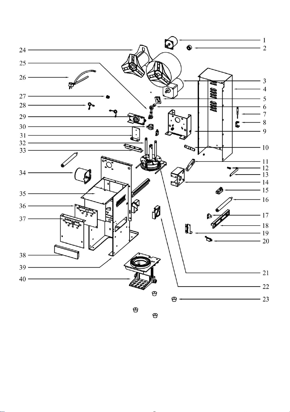
WY-890 Main Structure:

- 17 -
Exploded View Part list
(WY-890)
1.Small Motor
21.Upper Mould Component
2.Locating Sleeve
22.Pulley Guide Rail
3.Big Motor
23.Rubber Feet
4.Back Cover Board
24.Shaft Sleeve of Film
5.Motor Rocker
25.Bearing Component of Joint
6.Rod Connecting Shaft
26.Power Cable
7.Little Screwdriver
27.Coil
8.Screwdriver Holder
28.Pinch Cock
9.Holding Structure of Motor
29.Rocker Baffle
10.Pulling Plate Motor Connecting Rod
30.Center Shaft Sleeve
11.Pulling Plate Motor Rocker
31.Travel Switch Mounting Plate
12.Film Fixed Spring
32.Guide Shaft
13.Film Fixed Plate
33.Guide Shaft stiffening Plate
14.Pulling Plate Motor Holder
34.Cup in Motor
15.Sensor
35.Top Cover
16.Scroll of Film
36.Control Board
17.Film Rolling Stick Holder
37.Panel
18.Rubber Stick
38.Front Board
19.Cup in Travel Holder
39.Machine Body
20.Travel Switch
40.Pulling Plate Component
- 18 -
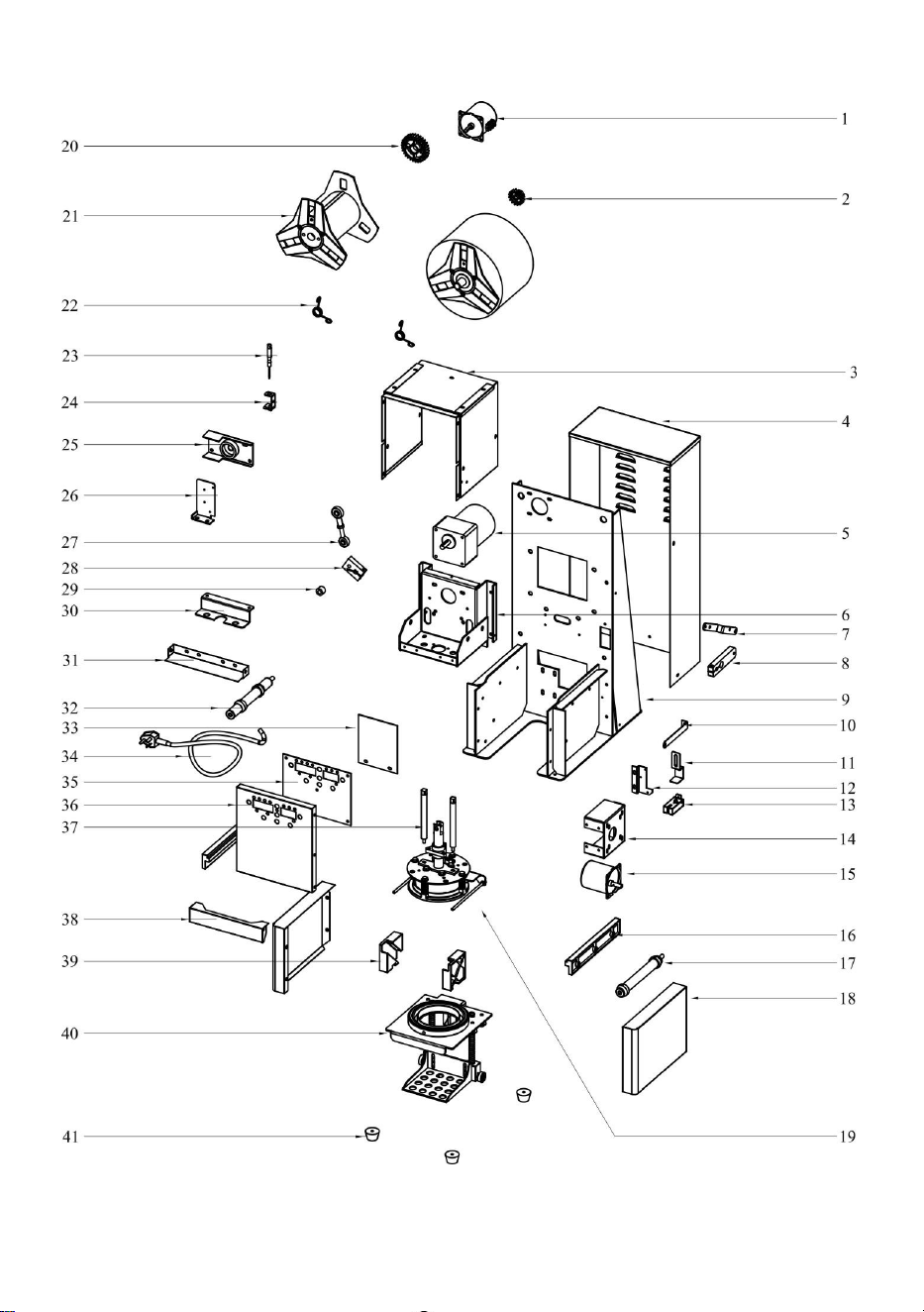
WY-980 Exploded View:

- 19 -
Exploded View Part list
(WY-980)
1.Small Motor
22.Pinch Cock
2.Small Gear
23.Little Screwdriver
3.Top Cover
24.Screwdriver Holder
4.Back Cover Board
25.Rocker Baffle
5.Big Motor
26.Travel Switch Mounting Plate
6.Holding Structure of Motor
27.Bearing Component of Joint
7.Pulling Plate Motor Connecting Rod
28.Motor Rocker
8.Pulling Plate Motor Rocker
29.Rod Connecting Shaft
9.Machine Body
30.Guide Shaft stiffening Plate
10.Film Fixed Plate
31.Front Board
11.Sensor Holder
32.Scroll of Film-left
12.Cup in Travel Holder
33.Wire Cover Plate
13.Sensor
34.Power Cable
14.Pulling Plate Motor Holder
35.Control Board
15.Cup in Motor
36.Panel
16.Rubber Stick
37.Guide Shaft
17.Scroll of Film-right
38.Safe Door
18.Right Cover
39.Pulley Guide Rail
19.Upper Mould Component
40.Pulling Plate Component
20.Big Gear
41.Rubber Feet
21.Shaft Sleeve of Film
- 20 -
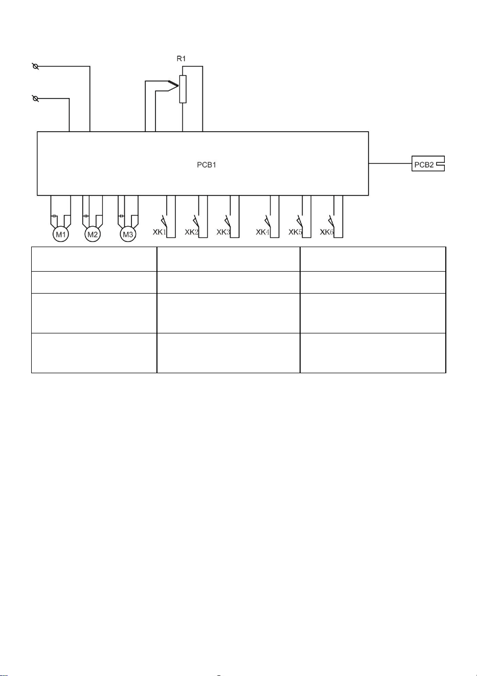
WY-890 & WY-980 Circuit diagram
R1:Heating
PCB1:Control panel
PBC2:Magic eye plate
M1:Cupping motor
M2:Cup joining motor
M3:Film rolling motor
Xk1:Safety door
travel switch
Xk2:Cup placing travel
switch
Xk3:Cupping down
travel switch
Xk4:cupping up
travel switch
Xk5:cup entering
travel switch
Xk6:cup outcome
travel switch

- 21 -
Address: Baoshanqu Shuangchenglu 803long 11hao 1602A-1609shi Shanghai
Imported to AUS: SIHAO PTY LTD. 1 ROKEVA STREETEASTWOOD NSW 2122
Australia
Imported to USA: Sanven Technology Ltd. Suite 250. 9166 Anaheim Place,
Rancho Cucamonga, CA 91730
REP
EC
SHUNSHUN GmbH
Römeräcker 9 Z2021, 76351
Linkenheim-Hochstetten, Germany
REP
UK
Pooledas Group Ltd
Unit 5 Albert Edward House, The
Pavilions Preston, United Kingdom
Made In China