

Thank you for purchasing a Honda tractor.
This manual describes operation and maintenance of the Honda H6522
compact tractor, type A2. (Two Wheel Drive Model) and type A4 (Four
Wheel Drive Model).
Information in this manual is based on the H6522 A4 model.
All information in this manual is based on the latest product information
available at the time of printing.
Honda Motor Co., Ltd. reserves the right to make changes at any time
without notice and without incurring any obligation.
No part of this publication may be reproduced without written permission.
This manual is considered a permanent part of the tractor and it must stay
with the tractor if resold.
READ THIS OWNER’S MANUAL CAREFULLY. Pay special attention to
these symbols and any instructions that follow:
m
-Indicates serious injuty or death WILL result if instructions
are not followed.
M
-Indicates a strong possibility that serious injury or death
could result if instructions are not followed.
m
-Indicates a possibility that minor injury can result if instruc-
tions are not followed.
riiGiq
-Indicates that equipment or property damage can result if
instructions are not followed.
NOTE: Gives helpful information.
Honda tractors are designed to give safe and dependable service if
operated according to instructions. Operating this tractor requires special
effort on your part to ensure your safety and the safety of others.
m
Using this product for a purpose not intended may cause injury
or property damage. Read and understand this Owner’s Manual before
operating this tractor.
If a problem should arise, or if you have any questions about your tractor,
consult an authorized Honda compact tractor dealer.
HONDA MOTOR CO., LTD. 1991, ALL RIGHTS RESERVED
1

CONTENTS
1. SAFETY INFORMATION
.......................................................
5
2. SERIAL NUMBERS
...............................................................
13
3. COMPONENT IDENTIFICATION
..............................................
14
4. CONTROLS
........................................................................
16
INSTRUMENT PANEL
..........................................................
16
1. Engine switch
...............................................................
17
2. Fuel gauge
....................................................................
18
3. Coolant temperature gauge
.............................................
18
4. Tachometer
..................................................................
19
5. Hour meter
...................................................................
19
6. Oil pressure warning light
................................................
20
7. Charge system warning light
............
. ..............................
20
8. Parking brake indicator/warning buzzer
..............................
21
9. Headlight switch/indicator
..............................................
22
10.
Flashing warning lights/indicator
...................................... 22
1 1. Glow plug indicator
........................................................
23
12.
Storage of Owner’s Manual
.............................................
23
OPERATING CONTROLS
......................................................
24
1. Throttle lever
................................................................
24
2. Throttle pedal
...............................................................
3. Parking brake lock
..........................................................
I:
4. Brake pedal
...................................................................
26
5. Clutch pedal
.................................................................
26
6. Main transmission selector/transmission range selector
........
27
7. Two- and four-wheel drive select lever (A4 type only)
..........
27
8. Differential lock pedal
.....................................................
28
9. Seat adjusting lever
........................................................
28
ATTACHMENT OPERATION SYSTEM
.................................... 29
1
.
PTO clutch lever
............................................................ 29
2.
PTO selector
.................................................................
30
3. Stationary PTO switch/indicator
.......................................
30
4. Rear PTO shaft/cover
.....................................................
31
5.
Lift control lever
............................................................
31
6. Lift control stop
.............................................................
32
7. Lowering speed control
..................................................
33
8.
Auxiliary hydraulic port
...................................................
34
5. PRE-OPERATION CHECKS
....................................................
35
WALK-AROUND CHECKS
.....................................................
35
2
1. Fuel
.............................................................................
36
2. Tires/wheels
.................................................................
38
UNDER-HOOD CHECKS
.......................................................
39
1. Open/close hood
...........................................................
39
2. Side column cover removal
..............................................
40
3. Engine oil
.....................................................................
41
4. Coolant
........................................................................
42
5. Battery
........................................................................
44
6. Fuel filter
......................................................................
45
7. Fan belt
.......................................................................
45
8. Power steering belt
........................................................
46
9. Radiator screen
.............................................................
46
10. Battery under tray ..........................................................
47
OPERATOR-PLATFORM CHECKS
..........................................
48
1. Steering
.......................................................................
48
2. Lights ..........................................................................
48
3. Clutch pedal
.................................................................
49
4. Brake pedals
.................................................................
49
5. Parking brake warning buzzer ..........................................
50
6. Safety interlock system
..................................................
51
6. OPERATION
.......................................................................
54
1. Starting the engine
.........................................................
54
2. Starting/driving
.............................................................
57
3. Warm up and break in operation
.......................................
61
4. Check hydraulic lift
........................................................ 61
5. Stopping the engine .......................................................
62
6. Turning
. . . . . . . . . . y . . . . . . . . . . . . . . . . . . . . . . . . . . . . . . . . . . . . . . . . . . . .
7. How to use the differential lock
. . . . . . . . . . . . . . . . . . . . . . .
8. Two and four-wheel drive selection (A4 type only
,i
9. Use of power steering
. . . . . . . . . . . . . . . . . . . . . . . . . . . . . . . . . . .
10. Attachment limitation
. . . . . . . . . . . . . . . . . . . . . . . . . . . . . . . . . . . .
1 1 . Operation on a slope
. . . . . . . . . . . . . . . . . . . . . . . . . . . . . . . . . . . . . .
................
65
................ 67
............... 69
................ 70
................
71
................ 79
12. Uphill starting procedure
.................................................
80
13. Recommended working speed .........................................
81
7. TRANSPORTING
.................................................................
82
8. INSTALLING AN ATTACHMENT ............................................
84
1
.
Rear 3-point hitch link installation (option)
..........................
84
2. Rear 3-point hitch attachment installation
..........................
86
3
9. MAINTENANCE
,...,.............................................................
88
1 .
Tool kit . . . . . . . . . . . . . . . . . . . . . . . . . . . . . . . . . . . . . . . . . . . . . . . . . . . . . . . . . . . . . . . . . . . . . . . .
89
2.
Maintenance schedule
. . . . . . . . . . . . . . . . . . . . . . . . . . . . . . . . . . . . . . . . . . . . . . . . . . . .
90
3.
Engine oil change . . . . . . . . . . . . . . . . . . . . . . . . . . . . . . . . . . . . . . . . . . . . . . . . . . . . . . . . . . .
92
4.
Air cleaner service
. . . . . . . . . . . . . . . . . . . . . . . . . . . . . . . . . . . . . . . . . . . . . . . . . . . . . . . . .
94
5.
Transmission fluid . . . . . . . . . . . . . . . . . . . . . . . . . . . . . . . . . . . . . . . . . . . . . . . . . . . . . . . . .
96
6. Power steering fluid
. . . . . . . . . . . . . . . . . . . . . . . . . . . . . . . . . . . . . . . . . . . . . . . . . . . . . . .
98
7. Front axle case oil change (A4 type only)
. . . . . . . . . . . . . . . . . . . . . . . . . . .
99
8. All fasteners tightness/lubrication points
. . . . . . . . . . . . . . . . . . . . . . . . . . .
100
9. Fuel filter
. . . . . . . . . . . . . . . . . . . . . . . . . . . . . . . . . . . . . . . . . . . . . . . . . . . . . . . . . . . . . . . . . . . . . .
102
10. Radiator core cleaning
..,.................................................
103
11. Battery service
. . . . . . . . . . . . . . . . . . . . . . . . . . . . . . . . . . . . . . . . . . . . . . . . . . . . . . . . . . . . . .
104
12. Wheel removal
. . . . . . . . . . . .._................................................ 106
13. Fuse replacement
. . . . . . . . . . . . . . . . . . . . . . . . . . . . . . . . . . . . . . . . . . . . . . . . . . . . . . . . . . 107
14.
Bulb replacement . . . . . . . . . . . . . . . . . . . . . . . . . . . . . . . . . . . . . . . . . . . . . . . . . . . . . . . . . . . 109
10. LONG TERM STORAGE
. . . . . . . . . . . . . . . . . . . . . . . . . . . . . . . . . . . . . , . . . . . . . . . . . . . . . . . . 1 10
Storage . . . . . . . . . . . . . . . . . . . . . . . . . . . . . . . . . . . . . . . . . . . . . . . . . . . . . . . . . . . . . . . . . . . . . . . . 1 : y
Removal storage
. . . . . . . . . . . . . . . . . . . . . . . . . . . . . . . . . . . . . . . . . . . . . . . . . . . . . . . . . . .
11. TROUBLESHOOTING
. . . . . . . . . . . . . . . . . . . . . . . . . . . . . . . . . . . . . . . . . . . . . . . . . . .
. . . . . . . . 112
12. SPECIFICATIONS
. . . . . . . . . . . . . . . . . . . . . . . . . . . . . . . . . . . . . . . . . . . . . . . . . . . . . . . .
. . . . . . . . 115
13. WARRANTY SERVICE
. . . . . . . . . . . . . . . . . . . . . . . . . . . . . . . . . . . . . . . . . . . . . . . . . . . . . . . . . .
117
14. WIRING DIAGRAM
. . . . . . . . . . . . . . . . . . . . . . . . . . . . . . . . . . . . . . . . . . . . . . . . . . . . . .
. . . . . . . . 121
1. SAFETY INFORMATION
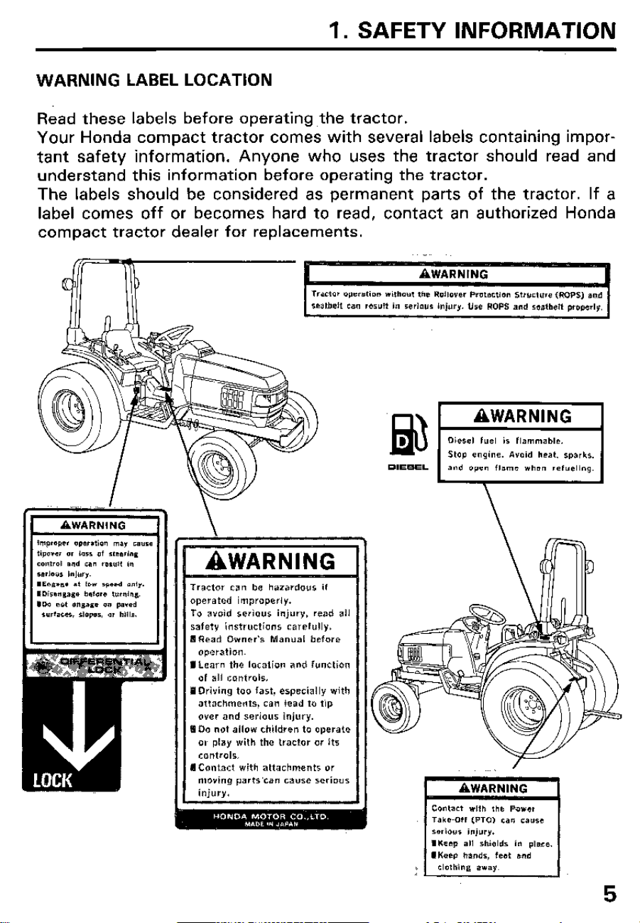
WARNING LABEL LOCATION
Read these labels before operating,the tractor.
Your Honda compact tractor comes with several labels containing impor-
tant safety information. Anyone who uses the tractor should read and
understand this information before operating the tractor.
The labels should be considered as permanent parts of the tractor. If a
label comes off or becomes hard to read, contact an authorized Honda
compact tractor dealer for replacements.
-_
.ji$ I-~
Stop engine. &void heat. sparks,
and open flame when refueling.
D’EeEL
\
AWARNING
Tractor can be hazardous if
operated improperly.
To avoid serious injury, read all
safety instructions carefully.
llRead Owner’s Manual before
operation.
I Learn the location and function
of all controls.
I Driving too fast. especially with
attachments. can lead to tip
over and serious injury.
I Do not allow children to operate
or play with the tractor or its
controls.
I Contact with attachments or
moving parts‘can cause serious
injury.
Contact with the Pow,
Take-Off (PTO) can CaUSe
serious injury.
IKeep all shields in place.
IKeep hands, feet and
clothing away.
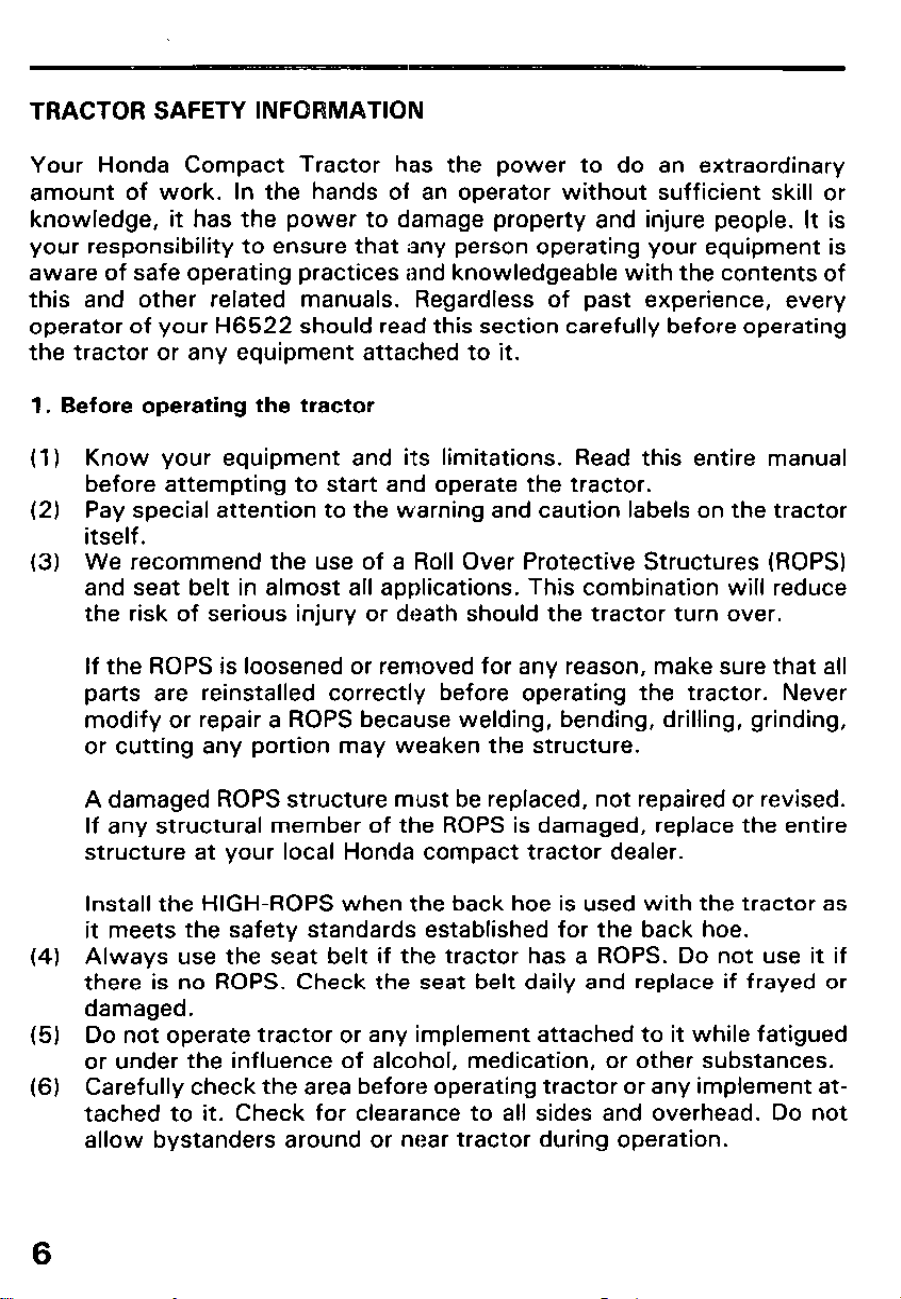
TRACTOR SAFETY INFORMATION
Your Honda Compact Tractor has the power to do an extraordinary
amount of work. In the hands of an operator without sufficient skill or
knowledge, it has the power to damage property and injure people. It is
your responsibility to ensure that any person operating your equipment is
aware of safe operating practices and knowledgeable with the contents of
this and other related manuals. Regardless of past experience, every
operator of your H6522 should read this section carefully before operating
the tractor or any equipment attached to it.
1. Before operating the tractor
(1)
(2)
(3)
(4)
(5)
(6)
Know your equipment and its limitations. Read this entire manual
before attempting to start and operate the tractor.
Pay special attention to the warning and caution labels on the tractor
itself.
We recommend the use of a Roll Over Protective Structures (ROPS)
and seat belt in almost all applications. This combination will reduce
the risk of serious injury or death should the tractor turn over.
If the ROPS is loosened or removed for any reason, make sure that all
parts are reinstalled correctly before operating the tractor. Never
modify or repair a ROPS because welding, bending, drilling, grinding,
or cutting any portion may weaken the structure.
A damaged ROPS structure must be replaced, not repaired or revised.
If any structural member of the ROPS is damaged, replace the entire
structure at your local Honda compact tractor dealer.
Install the HIGH-ROPS when the back hoe is used with the tractor as
it meets the safety standards established for the back hoe.
Always use the seat belt if the tractor has a ROPS. Do not use it if
there is no ROPS. Check the seat belt daily and replace if frayed or
damaged.
Do not operate tractor or any implement attached to it while fatigued
or under the influence of alcohol, medication, or other substances.
Carefully check the area before operating tractor or any implement at-
tached to it. Check for clearance to all sides and overhead. Do not
allow bystanders around or near tractor during operation.
6
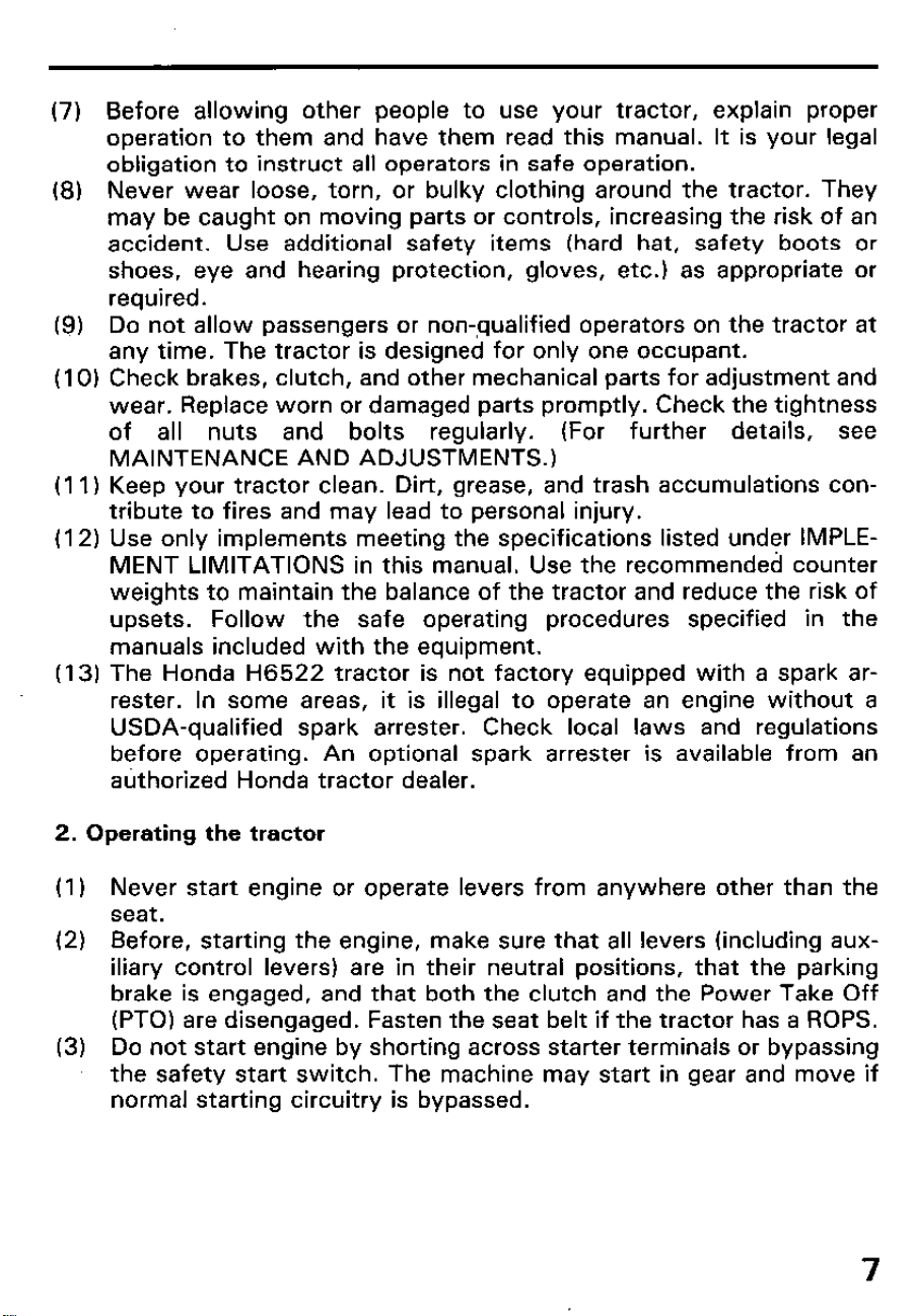
(7) Before allowing other people to use your tractor, explain proper
operation to them and have them read this manual. It is your legal
obligation to instruct all operators in safe operation.
(8) Never wear loose, torn, or bulky clothing around the tractor. They
may be caught on moving parts or controls, increasing the risk of an
accident. Use additional safety items (hard hat, safety boots or
shoes, eye and hearing protection, gloves, etc.) as appropriate or
required.
(g) Do not allow passengers or non-,qualified operators on the tractor at
any time. The tractor is designed for only one occupant.
(IO) Check brakes, clutch, and other mechanical parts for adjustment and
wear. Replace worn or damaged parts promptly. Check the tightness
of all nuts and bolts regularly. (For further details, see
MAINTENANCE AND ADJUSTMENTS.)
(11) Keep your tractor clean. Dirt, grease, and trash accumulations con-
tribute to fires and may lead to personal injury.
(12) Use only implements meeting the specifications listed under IMPLE-
MENT LIMITATIONS in this manual. Use the recommended counter
weights to maintain the balance of the tractor and reduce the risk of
upsets. Follow the safe operating procedures specified in the
manuals included with the equipment.
(13) The Honda H6522 tractor is not factory equipped with a spark ar-
rester. In some areas, it is illegal to operate an engine without a
USDA-qualified spark arrester.
Check local laws and regulations
before operating. An optional spark arrester is available from an
authorized Honda tractor dealer.
2. Operating the tractor
(1) Never start engine or operate levers from anywhere other than the
seat.
(2) Before, starting the engine, make sure that all levers (including aux-
iliary control levers) are in their neutral positions, that the parking
brake is engaged, and that both the clutch and the Power Take Off
(PTO) are disengaged. Fasten the seat belt if the tractor has a ROPS.
(3) Do not start engine by shorting across starter terminals or bypassing
the safety start switch. The machine may start in gear and move if
normal starting circuitry is bypassed.
7
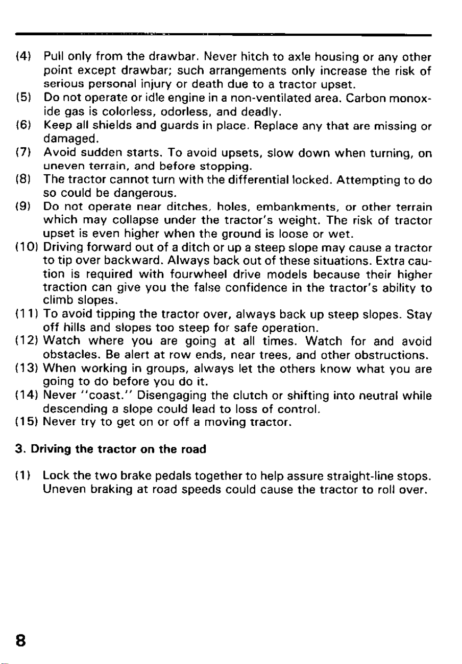
(4) Pull only from the drawbar. Never hitch to axle housing or any other
point except drawbar; such arrangements only increase the risk of
serious personal injury or death due to a tractor upset.
(5) Do not operate or idle engine in a non-ventilated area. Carbon monox-
ide gas is colorless, odorless, and deadly.
(6) Keep all shields and guards in place. Replace any that are missing or
damaged.
(7) Avoid sudden starts. To avoid upsets, slow down when turning, on
uneven terrain, and before stopping.
(8) The tractor cannot turn with the differential locked. Attempting to do
so could be dangerous.
(9) Do not operate near ditches, holes, embankments, or other terrain
which may collapse under the tractor’s weight. The risk of tractor
upset is even higher when the ground is loose or wet.
(I 0) Driving forward out of a ditch or up a steep slope may cause a tractor
to tip over backward. Always back out of these situations. Extra cau-
tion is required with fourwheel drive models because their higher
traction can give you the false confidence in the tractor’s ability to
climb slopes.
(I I) To avoid tipping the tractor over, always back up steep slopes. Stay
off hills and slopes too steep for safe operation.
(I 2) Watch where you are going at all times. Watch for and avoid
obstacles. Be alert at row ends, near trees, and other obstructions.
(13) When working in groups, always let the others know what you are
going to do before you do it.
(I 4) Never “coast.” Disengaging the clutch or shifting into neutral while
descending a slope could lead to loss of control.
(I 5) Never try to get on or off a moving tractor.
3. Driving the tractor on the road
(I 1 Lock the two brake pedals together to help assure straight-line stops.
Uneven braking at road speeds could cause the tractor to roll over.
8
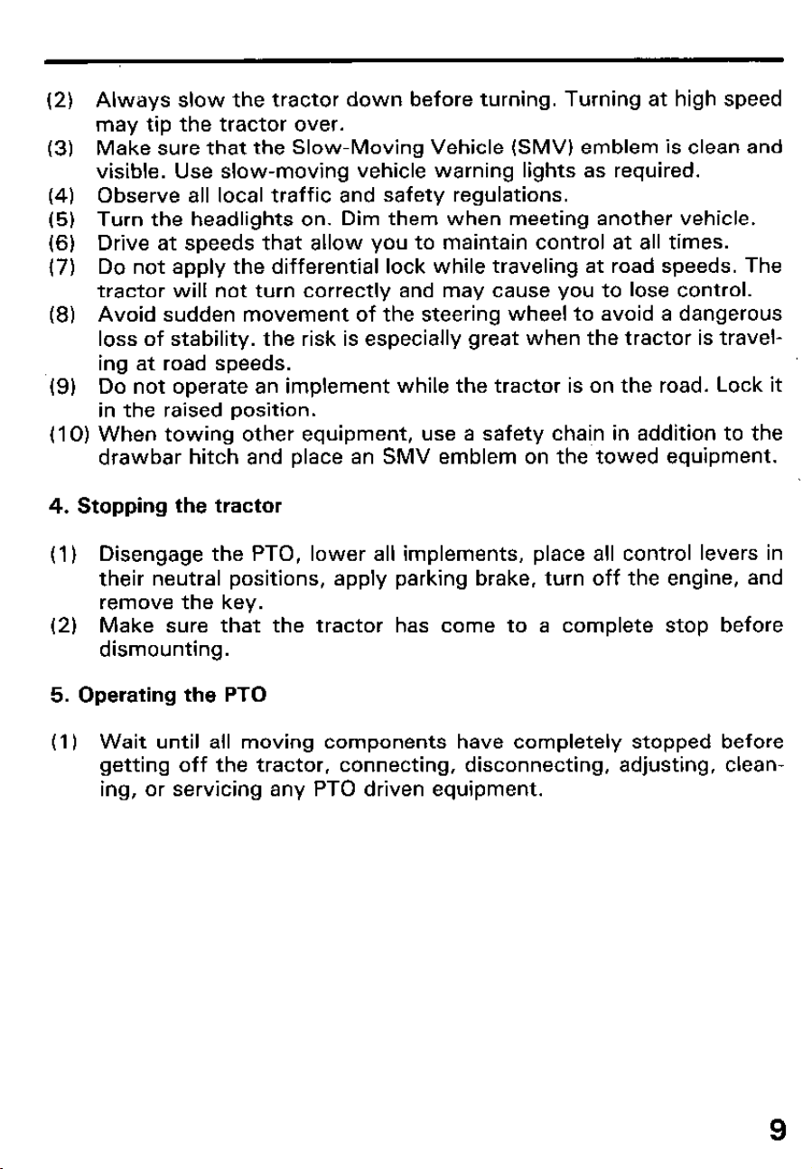
(2) Always slow the tractor down before turning. Turning at high speed
may tip the tractor over.
(3) Make sure that the Slow-Moving Vehicle (SMV) emblem is clean and
visible. Use slow-moving vehicle warning lights as required.
(4) Observe all local traffic and safety regulations.
(5) Turn the headlights on. Dim them when meeting another vehicle.
(6) Drive at speeds that allow you to maintain control at all times.
(7) Do not apply the differential lock while traveling at road speeds. The
tractor will not turn correctly and may cause you to lose control.
(8) Avoid sudden movement of the steering wheel to avoid a dangerous
loss of stability. the risk is especially great when the tractor is travel-
ing at road speeds.
(9) Do not operate an implement while the tractor is on the road. Lock it
in the raised position.
(I 0) When towing other equipment, use a safety chain in addition to the
drawbar hitch and place an SMV emblem on the towed equipment.
4. Stopping the tractor
(1) Disengage the PTO, lower all implements, place all control levers in
their neutral positions, apply parking brake, turn off the engine, and
remove the key.
(2) Make sure that the tractor has come to a complete stop before
dismounting.
5. Operating the PTO
(I) Wait until all moving components have completely stopped before
getting off the tractor, connecting, disconnecting, adjusting, clean-
ing, or servicing any PTO driven equipment.
9
(2) Keep the PTO shaft cover in place at all times. Replace the PTO shaft
cap when the shaft is not in use.
(3) Before installing or using PTO driven equipment, read the manufac-
turer’s manual and review the safety labels attached to the
equiprnent.
(4) Operate PTO-driven equipment at or below the rated RPM marked on
the tachometer.
(5) When operating stationary PTO-driven equipment, always apply the
tractor parking brake and place chocks behind and in front of the rear
wheels. Stay clear of all rotating parts.
6. Using 3-point hitch
(I I Use the 3-point hitch only with equipment designed for 3-point hitch
usage.
(2) When using a 3-point hitch mounted implement, be sure to install any
recommended counter-weight on the front of the tractor.
(3) When transporting on the road, set the implement lowering control in
the “lock” positon to hold the implement in the raised position.
7. Servicing the tractor
Before servicing the tractor, park it on a firm level surface, set the parking
brake, place the gear shift lever in neutral and stop the engine.
(1) Allow the tractor time to cool off before working on or near the
engine, muffler, radiator, etc.
(2) Always stop the engine before refueling. Avoid spills and overfilling.
(3) Do not smoke when working around battery or when refueling. Keep
all sparks and flames away from battery and fuel tank. The battery
presents an explosion hazard because it gives off hydrogen and
oxygen; especially when recharging.
(4) Before “jumping” a dead battery,
read and follow all of the
instructions.
(5) Keep first aid kit and fire extinguisher handy at all times.
10
(6) Do not remove radiator cap while coolant is hot. Add coolant to the
coolant recovery tank, not to the radiator.
(7) Disconnect the battery’s ground cable before working on or near
electric components.
(8) To avoid sparks from an accidental short circuit, always disconnect
the battery’s ground cable first and connect it last.
(9) Do not attempt to mount a tire on a rim unless qualified to do so and
all proper safety precautions are followed.
(IO) Provide adequate support when changing wheels.
(11) Make sure that wheel bolts have been tightened to the specified
torque.
(12) Escaping hydraulic fluid under pressure has sufficient force to
penetrate skin, causing serious personal injury. Before disconnecting
hydraulic lines, be sure to release all residual pressure. Before apply-
ing pressure to the hydraulic system, make sure that all connections
are tight and that all lines, pipes, and hoses are free of damage.
Fluid escaping from pinholes may not be visible. Do not use your bare
hands to search for suspected leaks. Use a piece of cardboard or
wood, instead. The use of safety goggles or other eye protection is
also highly recommended.
If injured by escaping fluid, see a medical doctor at once. Fluid can
produce severe reactions.
8. Jump starting instructions and precautions
If ice is present or the battery is cracked, do not attempt to “jump start”
the vehicle.
(I) Bring a helper vehicle with a battery of the same voltage as disabled
tractor within easy cable reach. THE VEHICLES MUST NOT TOUCH.
(2) Engage the parking brakes of both vehicles and put the shift levers in
neutral. Turn off both key switches.
(3) Put on safety goggles and rubber gloves.
(4) Remove the vent caps from both batteries.
11
(5) Cover vent holes with damp rags, Do not allow the rag to touch the
battery terminals.
(6) Attach the red clamp to the positive (red, (+) or pos.) terminal of the
dead battery and clamp the other end of the same cable to the
positive (red, (+) or pos.) termianl of the helper bettery.
(7) Clamp the other cable to the negative (black, (-) or neg.) terminal of
the helper battery.
(8) Clamp the other end to the engine block or frame of the disabled trac-
tor as far from the dead battery as possible.
(9) Start the helper vehicle and let its engine run for a few moments.
Start the disabled tractor.
(I 0) Disconnect the jumper cables in the exact reverse order of attach-
ment. (Steps 8, 7 and 6).
(I 1) Remove and discard the damp rags since they may contain sulfuric
acid. Reinstall the vent caps.
12
2. SERIAL NUMBERS
Record the frame and engine serial numbers for your reference. Refer to
the serial numbers when ordering parts, and when making technical or
warranty inquires (see page 117).
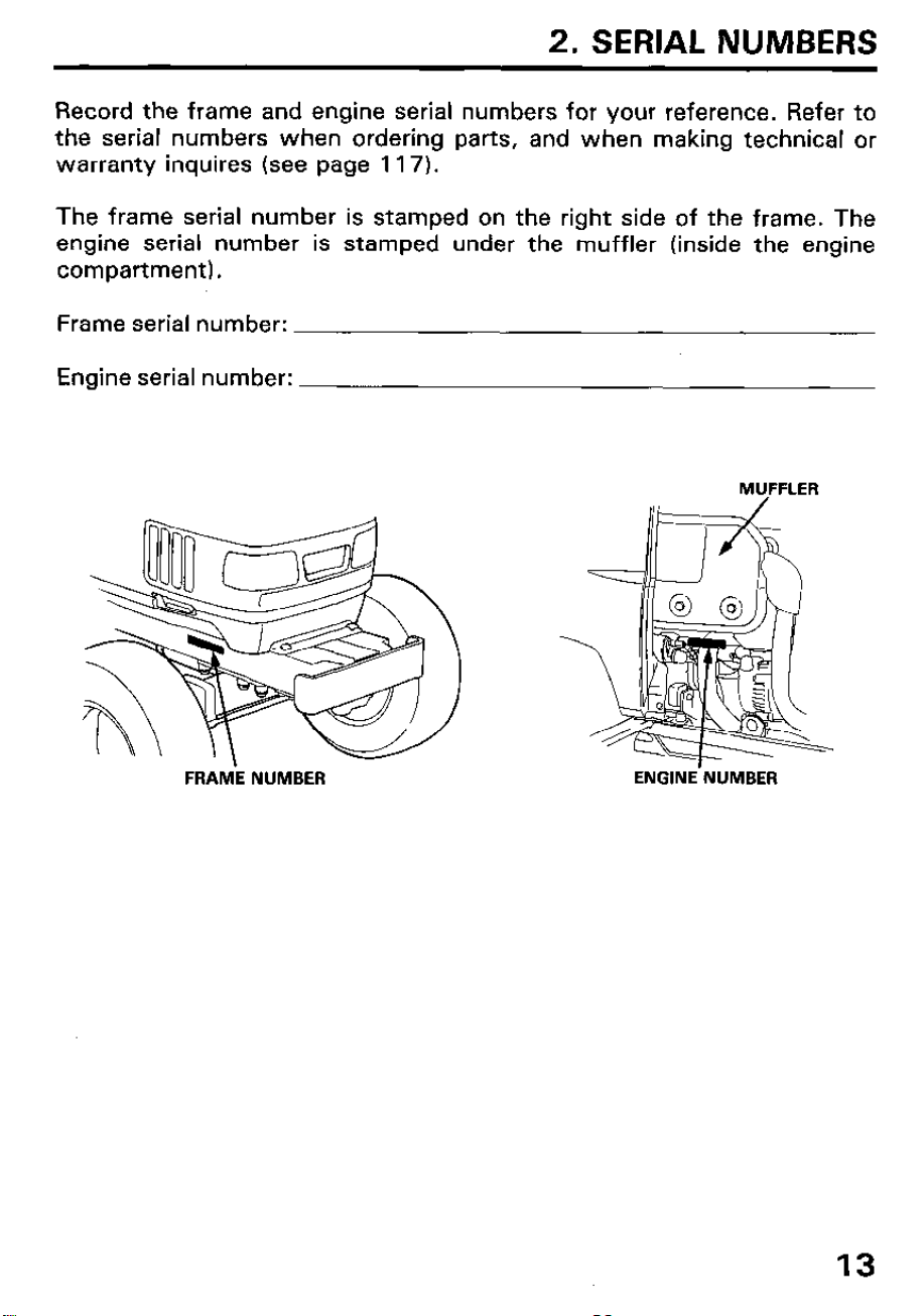
The frame serial number is stamped on the right side of the frame. The
engine serial number is stamped under the muffler (inside the engine
compartment).
Frame serial number:
Engine serial number:
MUFFLER
FRAME NUMBER
ENGINE’NUMBER
13
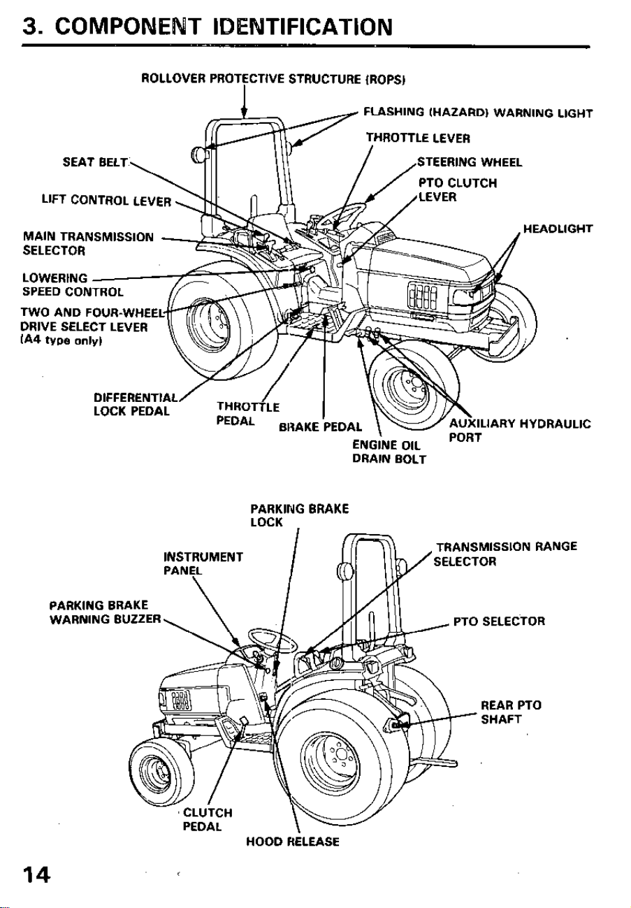
3. COMPONENT IDENTIFICATION
ROLLOVER PROTECTIVE STRUCTURE (ROPSJ
I
LlFT CONTROL LEVER
FLASHING (HAZARD) WARNING LIGHT
THROTTLE LEVER
STEERING WHEEL
PTO CLUTCH
MAIN TRANSMISSION
SELECTOR
SPEED CONTROL
TWO AND FOUR-WHEE
DRIVE SELECT LEVER
IA4 type only)
DIFFERENTIAL
LOCK PEDAL
IARY HYDRAULIC
ENGINE OIL
DRAIN BOLT
PARKING BRAKE
LOCK
TRANSMISSION RANGE
INSTRUMENT
SELECTOR
-__.-.
_ PTO SELECTOR
PARKING BRAKE
WARNING BUZZER
CLUTCH
REAR PTO
SHAFT
HOOD HELEASE
14
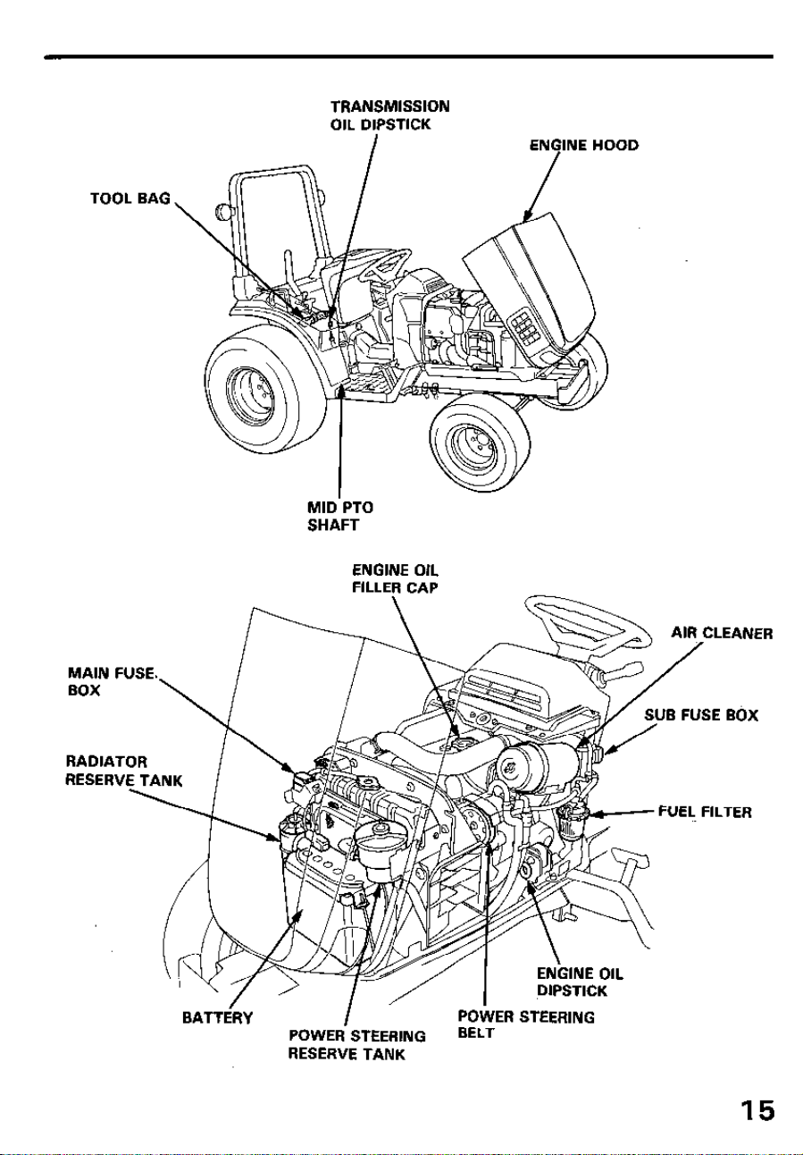
TRANSMISSION
OIL DIPSTICK
I
ENGINE HOOD
TOOL BAG
MID’PTO
SHAFT
ENGINE OIL
FILLER CAP
-7-A /---
AIR CLEANER
MAIN FUSE. /
BOX
YT-/
RADIATOR
RESERVE TANK
BATTERY
I
POWER STEERING
POWER STEERING
BELT
RESERVE TANK
15
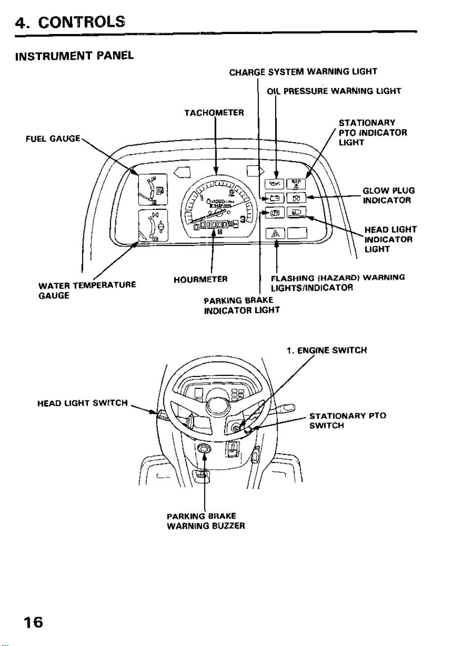
4. CONTROLS
INSTRUMENT PANEL
CHARGE SYSTEM WARNING LIGHT
I
OIL PRESSURE WARNING LIGHT
I
LIGHT
GLOW PLUG
INDICATOR
HEAD LIGHT
INDICATOR
/
WATER TEMPERATURE
HOURMETER
I
FLASHING (HAZARD) WARNING
LIGHTS/INDICATOR
GAUGE
PARKING BRAKE
INDICATOR LIGHT
HEAD LIGHT SWITCH
1. ENGINE SWITCH
STATIONARY PTO
PARKINd BRAKE
WARNING BUZZER
16
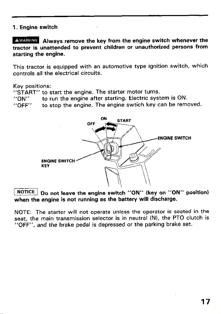
1. Engine switch
m
Always remove the key from the engine switch whenever the
tractor is unattended to prevent children or unauthorized persons from
starting the engine.
This tractor is equipped with an automotive type ignition switch, which
controls all the electrical circuits.
Key positions:
“START” to start the engine. The starter motor turns.
“ON”
to run the engine after starting. Electric system is ON.
“OFF” to stop the engine. The engine swtich key can be removed.
ENGINE SWITCH
KEY
SWITCH
1 NOTICE ( 0
o not leave the engine switch “ON” (key on “ON” position)
when the engine ,is not running as the battery will discharge.
NOTE: The starter will not operate unless the operator is seated in the
seat, the main transmission selector is in neutral (N), the PTO clutch is
“OFF”, and the brake pedal is depressed or the parking brake set.
17
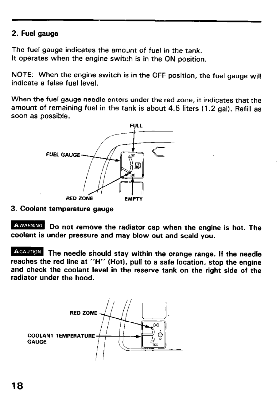
2. Fuel gauge
The fuel gauge indicates the amount of fuel in the tank.
It operates when the engine switch is in the ON position.
NOTE: When the engine switch is in the OFF position, the fuel gauge will
indicate a false fuel level.
When the fuel gauge needle enters under the red zone, it indicates that the
amount of remaining fuel in the tank is about 4.5 liters (1.2 gal). Refill as
soon as possible.
FUEL GAUGE
RED ZONE
EMPTY
3. Coolant temperature gauge
m Do not remove the radiator cap when the engine is hot. The
coolant is under pressure and may blow out and scald you.
m The needle should stay within the orange range. If the needle
reaches the red line at “H” (Hot), pull to a safe location, stop the engine
and check the coolant level in the reserve tank on the right side of the
radiator under the hood.
COOLANT
GAUGE
18
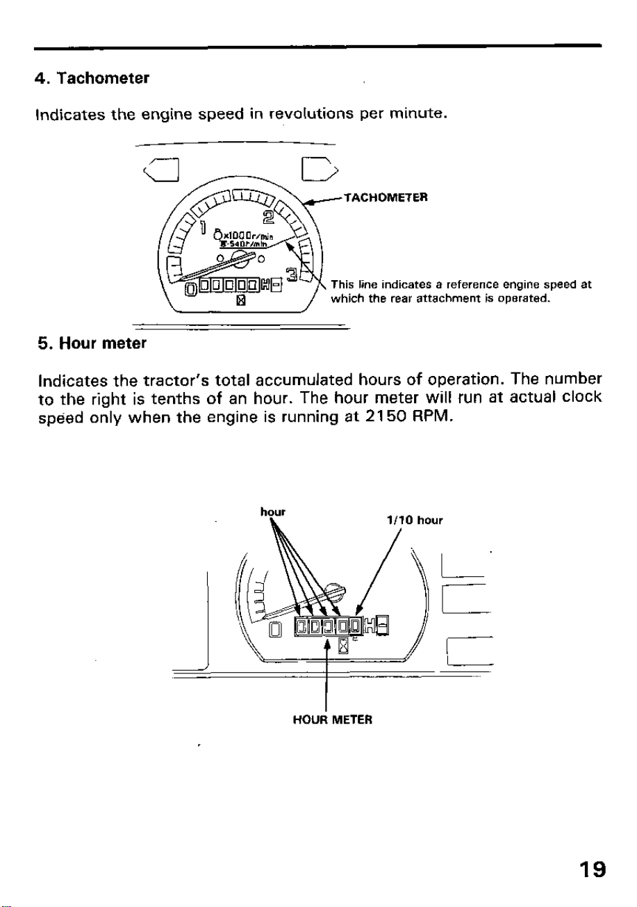
4. Tachometer
Indicates the engine speed in revolutions per minute.
TACHOMETER
This line indicates a reference engine speed at
which the rear attachment is operated.
5. Hour meter
Indicates the tractor’s total accumulated hours of operation. The number
to the right is tenths of an hour. The hour meter will run at actual clock
speed only when the engine is running at 2150 RPM.
HOUR METER
19
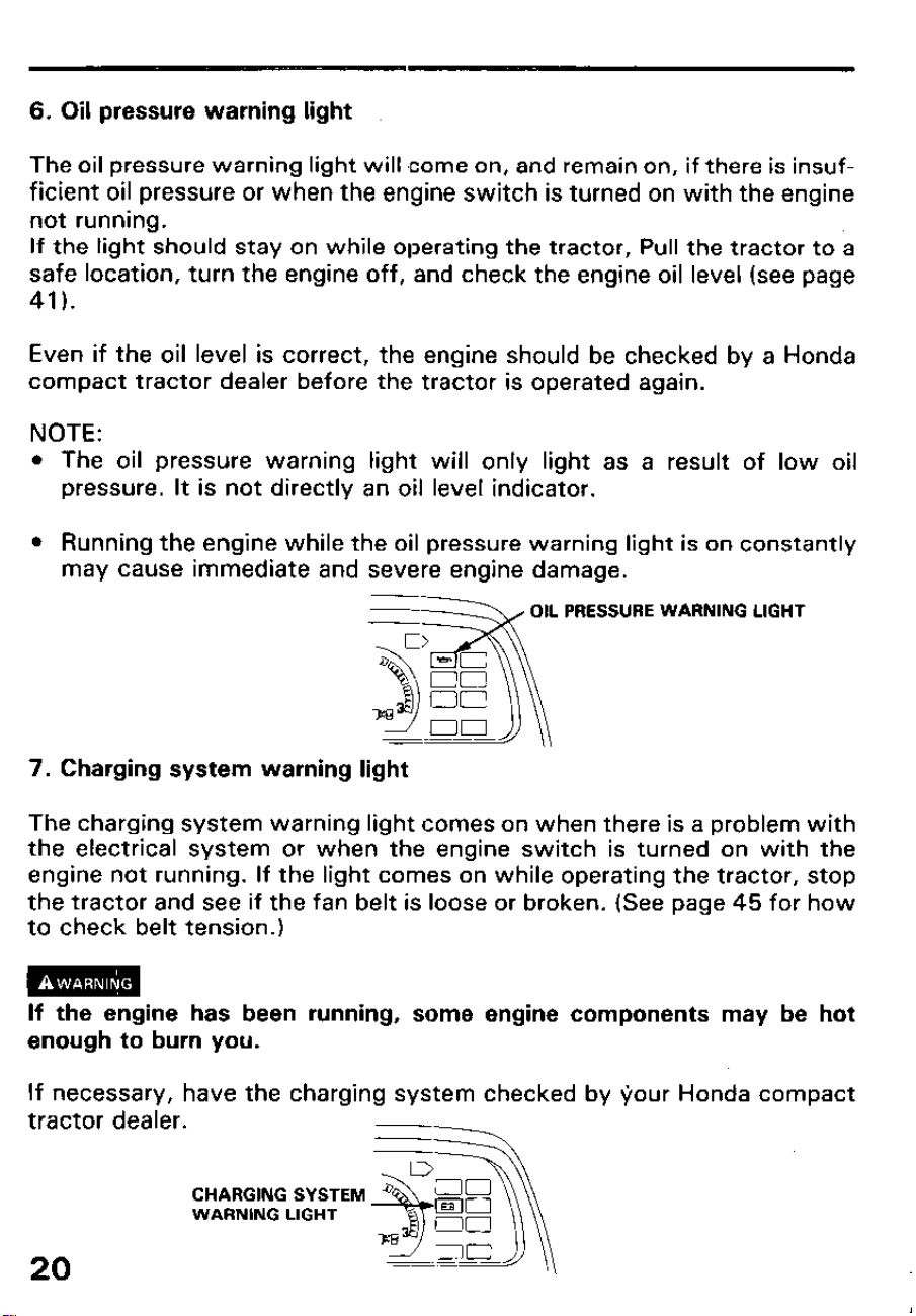
6. Oil pressure warning light
The oil pressure warning light will come on, and remain on, if there is insuf-
ficient oil pressure or when the engine switch is turned on with the engine
not running.
If the light should stay on while operating the tractor, Pull the tractor to a
safe location, turn the engine off, and check the engine oil level (see page
41).
Even if the oil level is correct, the engine should be checked by a Honda
compact tractor dealer before the tractor is operated again.
NOTE:
l The oil pressure warning light will only light as a result of low oil
pressure. It is not directly an oil level indicator.
l Running the engine while the oil pressure warning light is on constantly
may cause immediate and severe engine damage.
WARNING LIGHT
7. Charging system warning light
The charging system warning light comes on when there is a problem with
the electrical system or when the engine switch is turned on with the
engine not running. If the light comes on while operating the tractor, stop
the tractor and see if the fan belt is loose or broken. (See page 45 for how
to check belt tension.)
If the engine has been running, some engine components may be hot
enough to burn you.
If necessary, have the charging system checked by your Honda compact
tractor dealer.
CHARGING SYSTEM
WARNING LIGHT
20
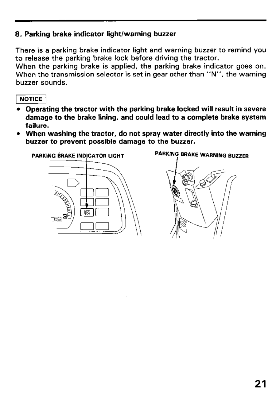
8. Parking brake indicator light/warning buzzer
There is a parking brake indicator light and warning buzzer to remind you
to release the parking brake lock before driving the tractor.
When the parking brake is applied, the parking brake indicator goes on.
When the transmission selector is set in gear other than “N”, the warning
buzzer sounds.
1 NOTICE 1
l Operating the tractor with the parking brake locked will result in severe
damage to the brake lining, and could lead to a complete brake system
failure.
l When washing the tractor, do not spray water directly into the warning
buzzer to prevent possible damage to the buzzer.
PARKiNG BRAKE ~NO~CATOR LIGHT
21
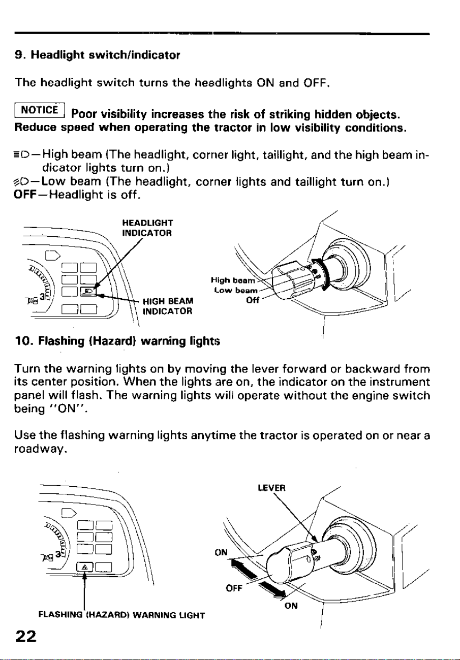
9. Headlight switch/indicator
The headlight switch turns the headlights ON and OFF.
1 NOTICE 1 p.
or visibility increases tlhe risk of striking hidden objects.
Reduce speed when operating the tractor in low visibility conditions.
ED-High beam (The headlight, corner light, taillight, and the high beam in-
dicator lights turn on.)
%O-Low beam (The headlight, corner lights and taillight turn on.)
OFF- Headlight is off.
HEADLIGHT
INDICATOR
HIGH SEAM
INDICATOR
10. Flashing (Hazard) warning lights
Turn the warning lights on by moving the lever forward or backward from
its center position. When the lights are on, the indicator on the instrument
panel will flash. The warning lights will operate without the engine switch
being “ON”.
Use the flashing warning lights anytime the tractor is operated on or near a
roadway.
FLASHING (HAZARD) WARNING LIGHT
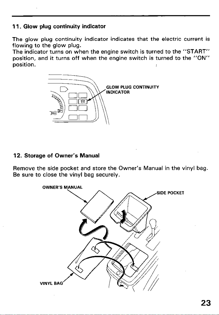
11. Glow plug continuity indicator
The glow plug continuity indicator indicates that the electric current is
flowing to the glow plug.
The indicator turns on when the engine switch is turned to the “START”
position, and it turns off when the engine switch is turned to the “ON”
position.
1
CONTINUITY
12. Storage of Owner’s Manual
Remove the side pocket and store the Owner’s Manual in the vinyl bag.
Be sure to close the vinyl bag securely.
OWNER’S MANUAL
VINYL BAG
POCKET
23
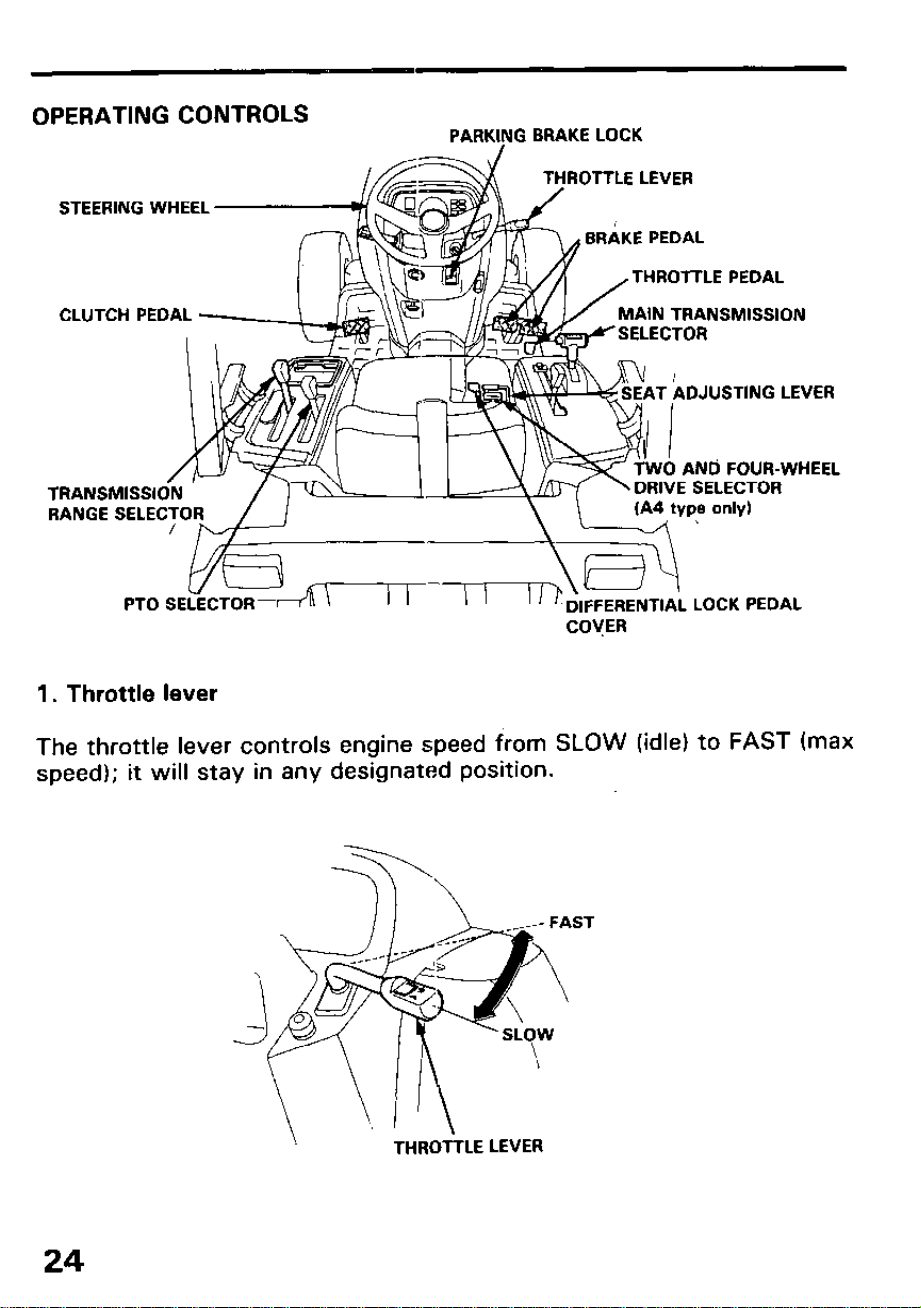
OPERATING CONTROLS
PARKIYG BRAKE LOCK
STEERING WHEEL -‘/)$$G
CLUTCH PEDAL
ROTTLE LEVER
THROTTLE PEDAL
MAIN TRANSMISSION
0 ANd FOUR-WHEEL
’ /
VE SELECTOR
.ECTOR RANGE SEI
PTO SELECTOR-‘+n \
I I
I I
I ’ ‘: DIFFERENTIAL LOCK PEDAL
COVER
1. Throttle lever
The throttle lever controls engine speed from SLOW (idle) to FAST (max
speed); it will stay in any designated position.
\.
THROtiLE LEVER
24
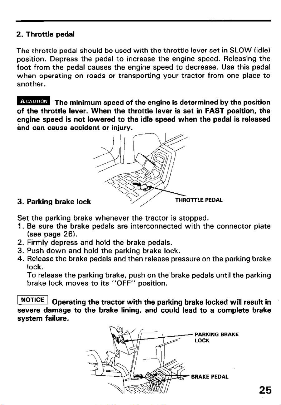
2. Throttle pedal
The throttle pedal should be used with the throttle lever set in SLOW (idle)
position. Depress the pedal to increase the engine speed. Releasing the
foot from the pedal causes the engine speed to decrease. Use this pedal
when operating on roads or transporting your tractor from one place to
another.
m
The minimum speed of the engine is determined by the position
of the throttle lever. When the throttle lever is set in FAST position, the
engine speed is not lowered to the idle speed when the pedal is released
and can cause accident or injury.
3. Parking brake lock
OTTLE PEDAL
Set the parking brake whenever the tractor is stopped.
1. Be sure the brake pedals are interconnected with the connector plate
(see page 26).
2. Firmly depress and hold the brake pedals.
3. Push down and hold the parking brake lock.
4. Release the brake pedals and then release pressure on the parking brake
lock.
To release the parking brake, push on the brake pedals until the parking
brake lock moves to its “OFF” position.
[I op
erating the tractor with the parking brake locked will result in
severe damage to the brake lining, and could lead to a complete brake
system failure.
PARKING BRAKE
LOCK
BRAKE PEDAL
25
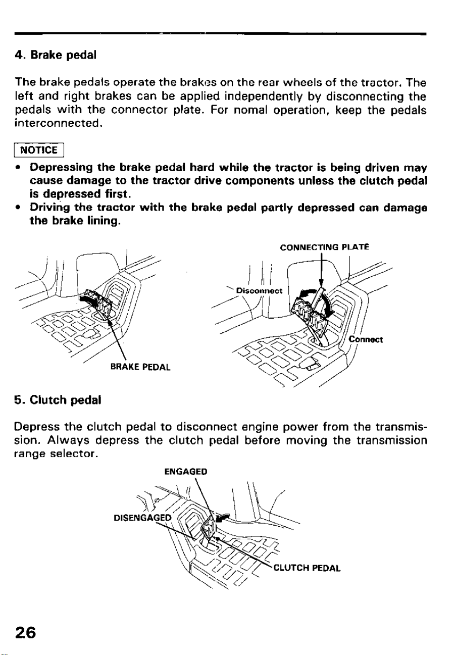
4. Brake pedal
The brake pedals operate the brakes on the rear wheels of the tractor. The
left and right brakes can be applied independently by disconnecting the
pedals with the connector plate. For nomal operation, keep the pedals
interconnected.
l Depressing the brake pedal hard while the tractor is being driven may
cause damage to the tractor drive components unless the clutch pedal
is depressed first.
l Driving the tractor with the brake pedal partly depressed can damage
the brake lining.
CONNECTING PLATE
BRAKE PEDAL
5. Clutch pedal
Depress the clutch pedal to disconnect engine power from the transmis-
sion. Always depress the clutch pedal before moving the transmission
range selector.
ENGAGED
CLUTCH PEDAL
26
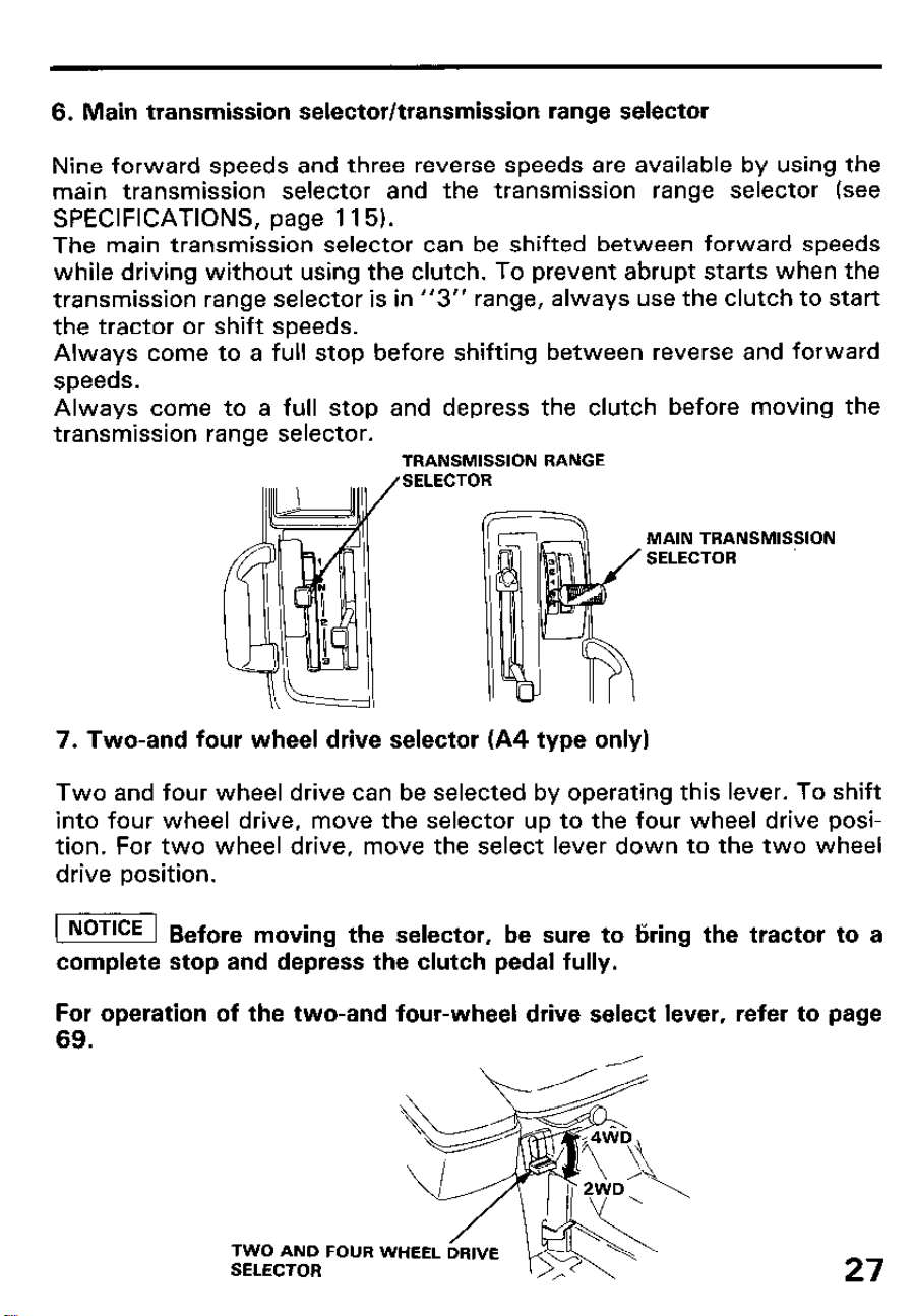
6. Main transmission selector/transmission range selector
Nine forward speeds and three reverse speeds are available by using the
main transmission selector and the transmission range selector (see
SPECIFICATIONS, page 115).
The main transmission selector can be shifted between forward speeds
while driving without using the clutch. To prevent abrupt starts when the
transmission range selector is in
“3” range, always use the clutch to start
the tractor or shift speeds.
Always come to a full stop before shifting between reverse and forward
speeds.
Always come to a full stop and depress the clutch before moving the
transmission range selector.
TRANSMISSION RANGE
SELECTOR
MAIN TRANSMISSION
SELECTOR
7. Two-and four wheel drive selector (A4 type only)
Two and four wheel drive can be selected by operating this lever. To shift
into four wheel drive, move the selector up to the four wheel drive posi-
tion. For two wheel drive, move the select lever down to the two wheel
drive position.
( Before moving the selector, be sure to tiring the tractor to a
complete stop and depress the clutch pedal fully.
For
69.
operation of the two-and four-wheel drive select lever,
TWO AND
SELECTOR
FOUR
refer to
27
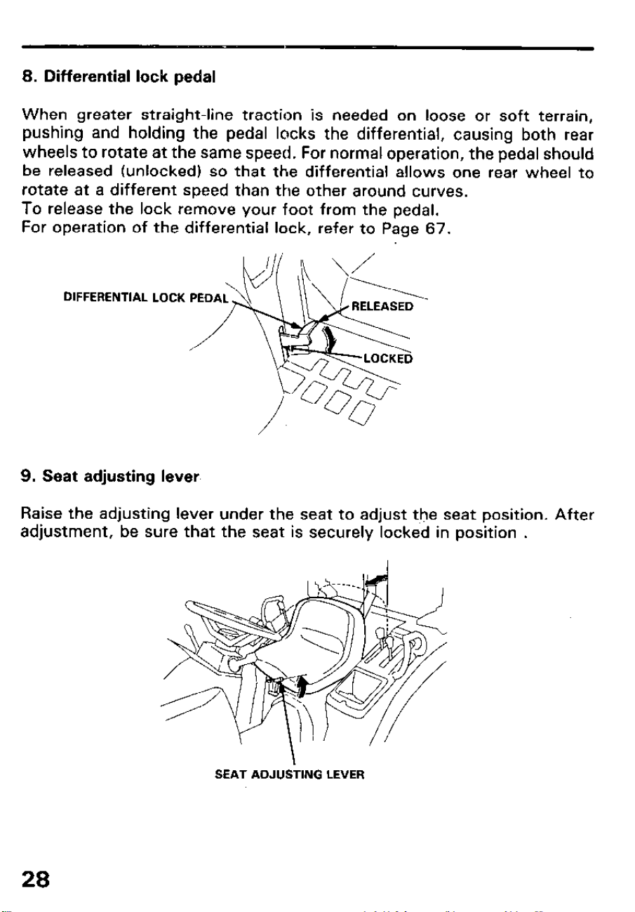
8. Differential lock pedal
When greater straight-line traction is needed on loose or soft terrain,
pushing and holding the pedal locks the differential, causing both rear
wheels to rotate at the same speed. For normal operation, the pedal should
be released (unlocked) so that the differential allows one rear wheel to
rotate at a different speed than the other around curves.
To release the lock remove your foot from the pedal.
For operation of the differential lock, refer to Page 67.
DIFFERENTIAL LOCK
9. Seat adjusting lever
Raise the adjusting lever under the seat to adjust the seat position. After
adjustment, be sure that the seat is securely locked in position .
SEAT ADJUSi-ING
LEVER
28
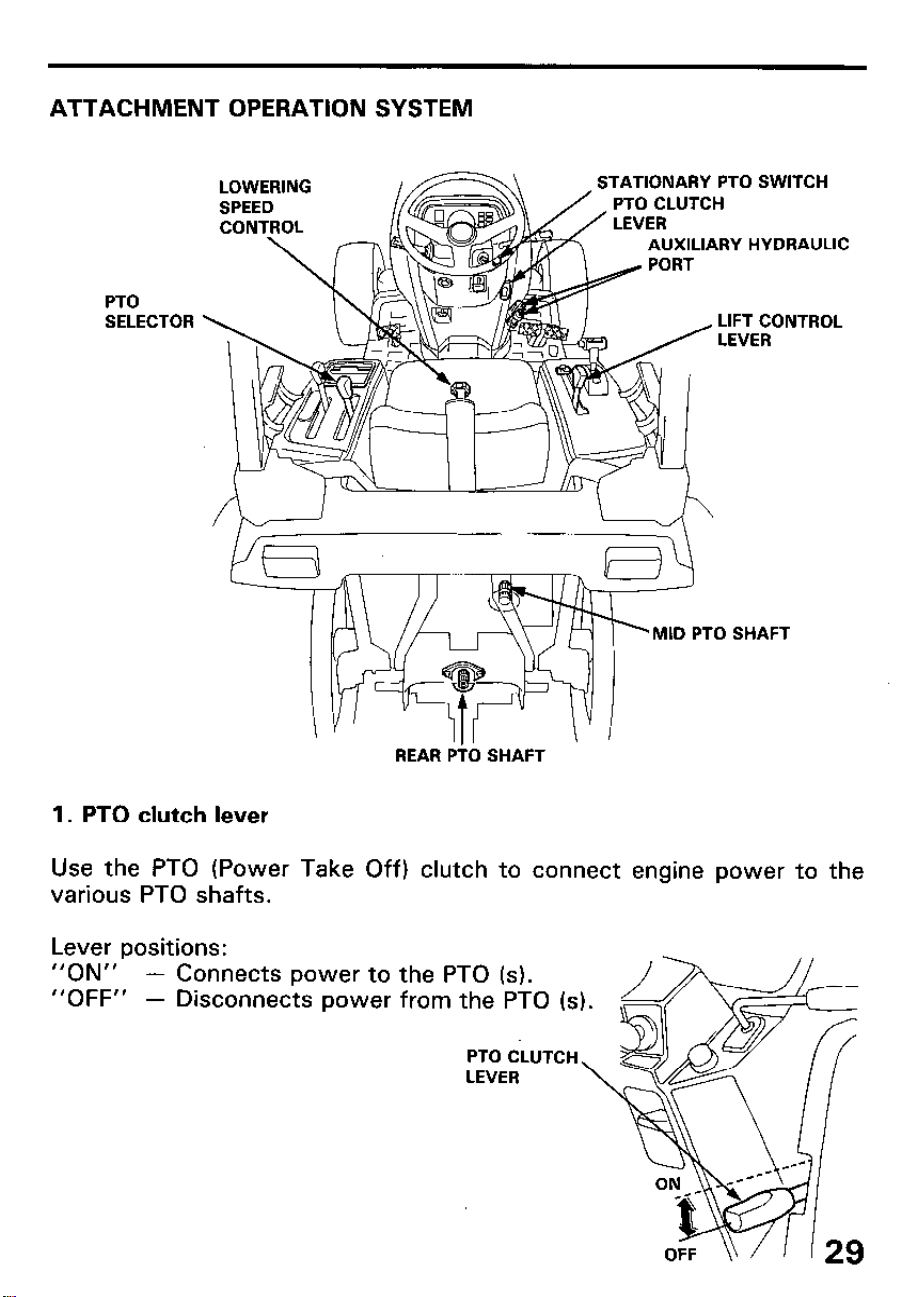
ATTACHMENT OPERATION SYSTEM
LOWERING
SPEED
CONTROL
TATIONARY PTO SWITCH
PTO CLUTCH
AUXILIARY HYDRAULIC
PTO
SELECTOR
LIFT CONTROL
LEVER
‘MID PTO SHAFT
REAR Pi0 SHAFT
1. PTO clutch lever
Use the PTO (Power Take Off) clutch to connect engine power to the
various PTO shafts.
Lever positions:
“ON”
- Connects power to
“OFF”
- Disconnects power
the PTO (s).
from the PTO is).
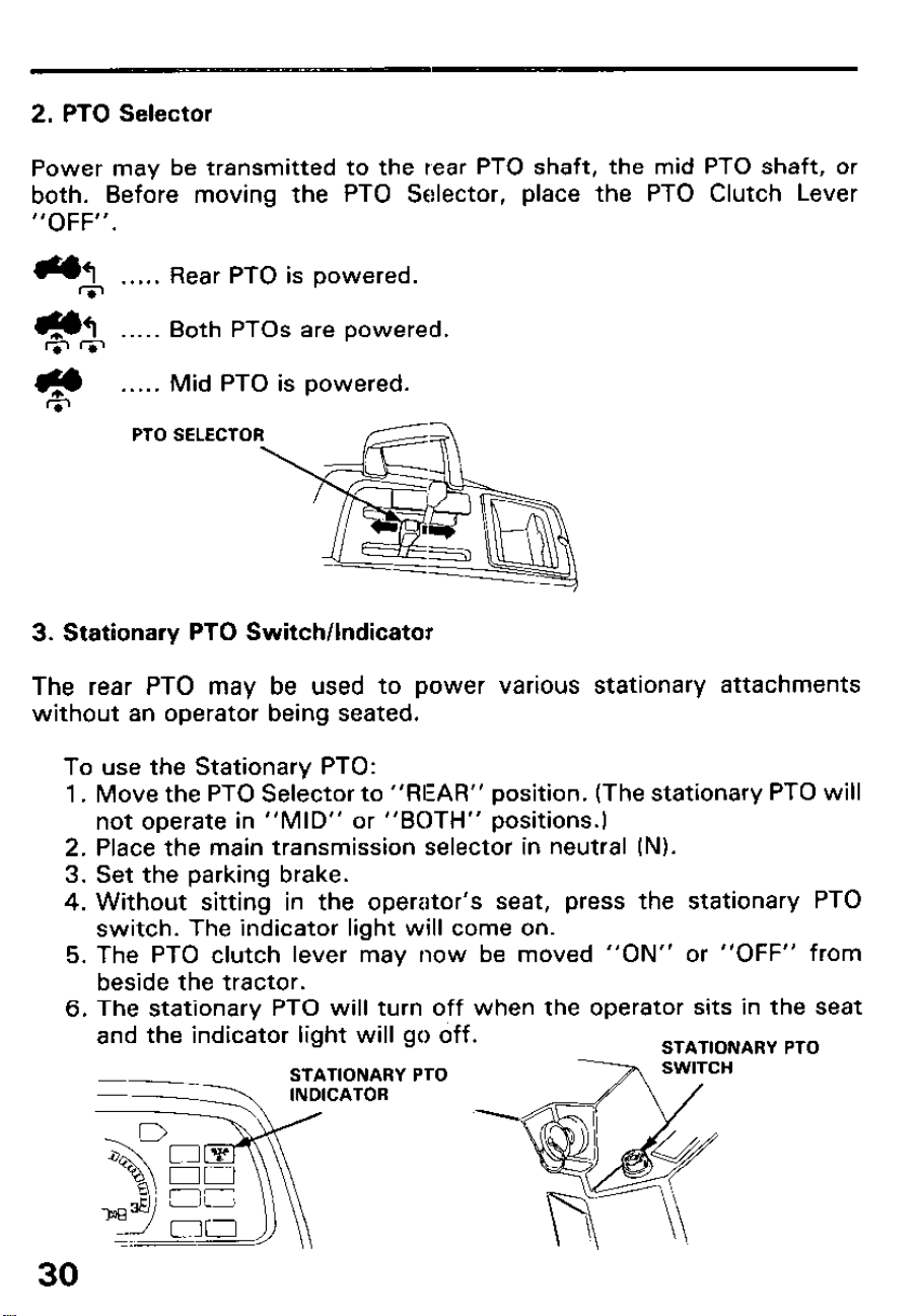
2. PTO Selector
Power may be transmitted to the rear PTO shaft, the mid PTO shaft, or
both. Before moving the PTO Selector, place the PTO Clutch Lever
“OFF”.
-1 . . . . .
ri-,
Rear PTO is powered.
-1
&m
. . . . . Both PTOs are powered.
. . . . .
Mid PTO is powered.
PTO SELECTOR
3. Stationary PTO Switch/Indicator
The rear PTO may be used to power various stationary attachments
without an operator being seated.
To use the Stationary PTO:
1.
2.
3.
4.
5.
6.
30
Move the PTO Selector to “REAR” position. (The stationary PTO will
not operate in “MID” or “BOTH” positions.)
Place the main transmission selector in neutral (N).
Set the parking brake.
Without sitting in the operator’s seat, press the stationary PTO
switch. The indicator light will come on.
The PTO clutch lever may now be moved “ON” or “OFF” from
beside the tractor.
The stationary PTO will turn off when the operator sits in the seat
and the indicator light will go off.
STATIONARY PTO
--
STATIONARY PTO
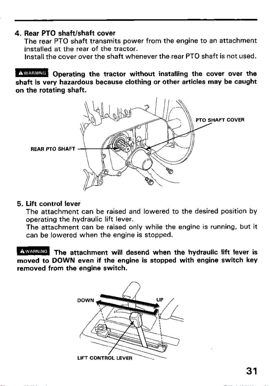
4. Rear PTO shaft/shaft cover
The rear PTO shaft transmits power from the engine to an attachment
installed at the rear of the tractor.
Install the cover over the shaft whenever the rear PTO shaft is not used.
m
Operating the tractor without installing the cover over the
shaft is very hazardous because clothing or other articles may be caught
on the rotating shaft.
AFT COVER
REAR PTO SHAFT
5. Lift control lever
The attachment can be raised and lowered to the desired position by
operating the hydraulic lift lever.
The attachment can be raised only while the engine is running, but it
can be lowered when the engine is stopped.
m
The attachment will desend when the hydraulic lift lever is
moved to DOWN even if the engine is stopped with engine switch key
removed from the engine switch.
31
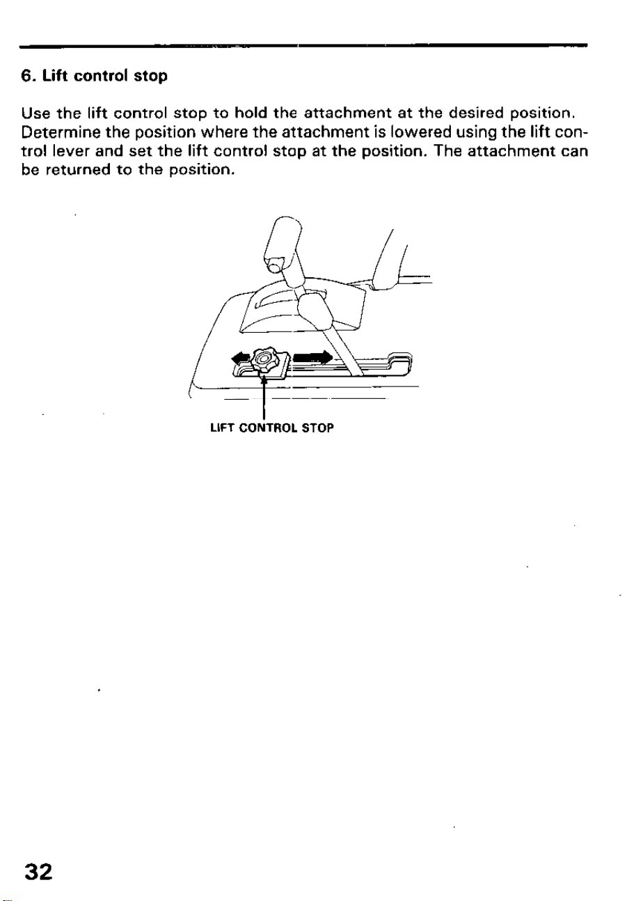
6. Lift control stop
Use the lift control stop to hold the attachment at the desired position.
Determine the position where the attachment is lowered using the lift con-
trol lever and set the lift control stop at the position. The attachment can
be returned to the position.
LIFT CONTROL STOP
32
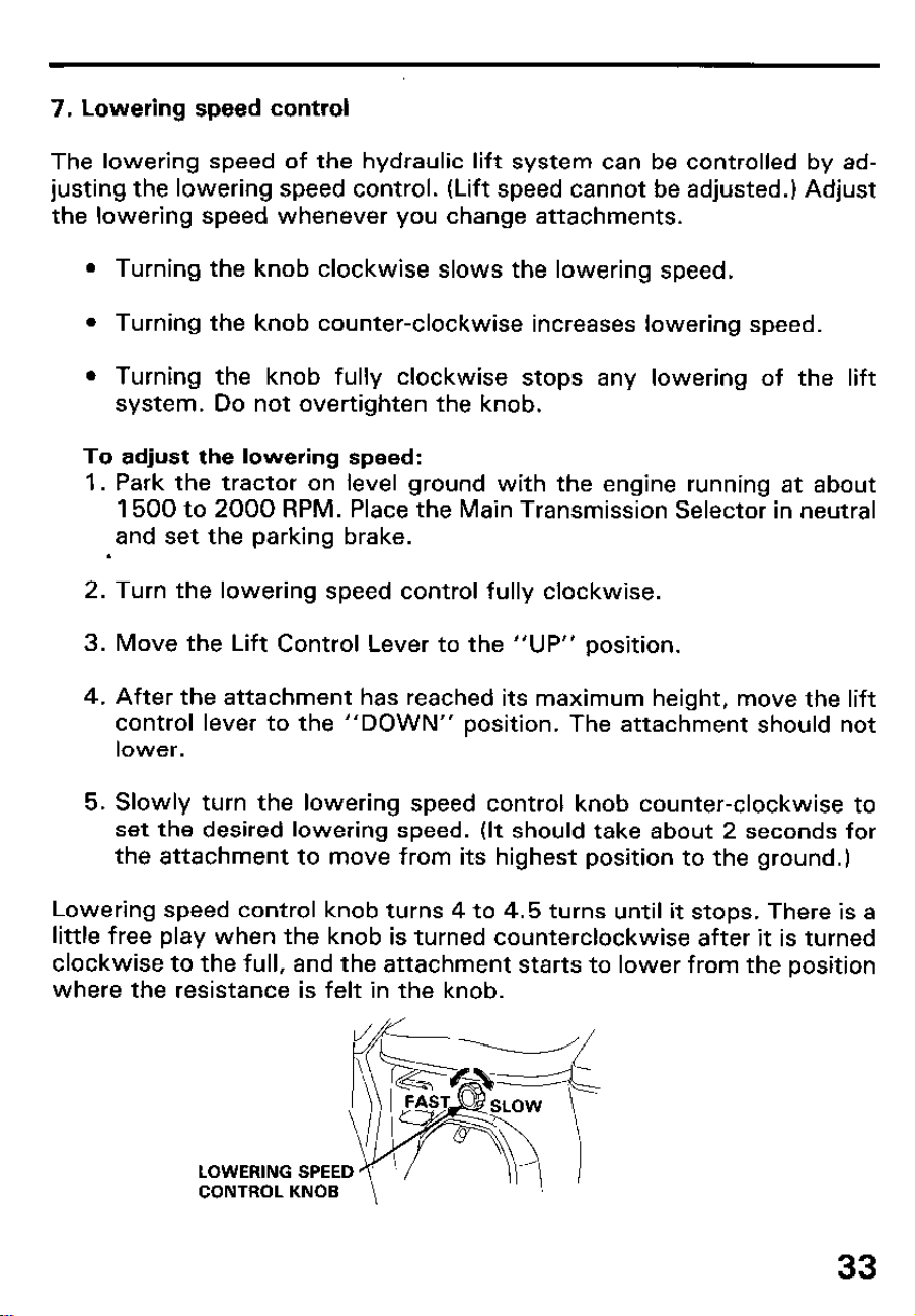
7. Lowering speed control
The lowering speed of the hydraulic lift system can be controlled by ad-
justing the lowering speed control. (Lift speed cannot be adjusted.) Adjust
the lowering speed whenever you change attachments.
l Turning the knob clockwise slows the lowering speed.
l Turning the knob counter-clockwise increases lowering speed.
l Turning the knob fully clockwise stops any lowering of the lift
system. Do not overtighten the knob.
To adjust the lowering speed:
1. Park the tractor on level ground with the engine running at about
1500 to 2000 RPM. Place the Main Transmission Selector in neutral
and set the parking brake.
.
2. Turn the lowering speed control fully clockwise.
3. Move the Lift Control Lever to the “UP” position.
4. After the attachment has reached its maximum height, move the lift
control lever to the “DOWN” position. The attachment should not
lower.
5. Slowly turn the lowering speed control knob counter-clockwise to
set the desired lowering speed. (It should take about 2 seconds for
the attachment to move from its highest position to the ground.)
Lowering speed control knob turns 4 to 4.5 turns until it stops. There is a
little free play when the knob is turned counterclockwise after it is turned
clockwise to the full, and the attachment starts to lower from the position
where the resistance is felt in the knob.
LOWERING SPEED
CONTROL KNOB
33
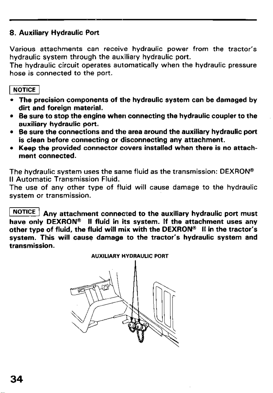
8. Auxiliary Hydraulic Port
Various attachments can receive hydraulic power from the tractor’s
hydraulic system through the auxiliary hydraulic port.
The hydraulic circuit operates automatically when the hydraulic pressure
hose is connected to the port.
l The precision components of the hydraulic system can be damaged by
dirt and foreign material.
l Be sure to stop the engine when connecting the hydraulic coupler to the
auxiliary hydraulic port.
l Be sure the connections and the area around the auxiliary hydraulic port
is clean before connecting or disconnecting any attachment.
l Keep the provided connector covers installed when there is no attach-
ment connected.
The hydraulic system uses the same fluid as the transmission: DEXRON@
II Automatic Transmission Fluid.
The use of any other type of fluid will cause damage to the hydraulic
system or transmission.
1 NOTICE ] A,,
y attachment connected to the auxiliary hydraulic port must
have only DEXRON
@ II fluid in its system. If the attachment uses any
other type of fluid, the fluid will mix with the DEXRON@ II in the tractor’s
system. This will cause damage to the tractor’s hydraulic system and
transmission.
AUXILIARY HYDRAULIC PORT
34
5. PRE-OPERATION CHECKS
For your personal safety and the service life of your equipment, always
perform checks before using your tractor.
Before beginning a pre-operation check, be sure:
l The tractor is parked on a level surface.
l The parking brake is set, the main transmission selector is in neutral (N),
and the PTO clutch lever is “OFF”.
l Any attachment is lowered to the ground and the lift control lever is in
the “DOWN” position.
l The engine switch key is removed.
WALK-AROUND CHECKS
Walk around the tractor and check its general condition.
Look around and underneath it for signs of fluid leaks.
Clean any excessive accumulation of dirt and debris, especially around
moving components. Look for signs of damage. Check nuts, bolts,
screws, and pins for tightness.
In particular, check the following items:
l Fuel level
l Tires/Wheels
35
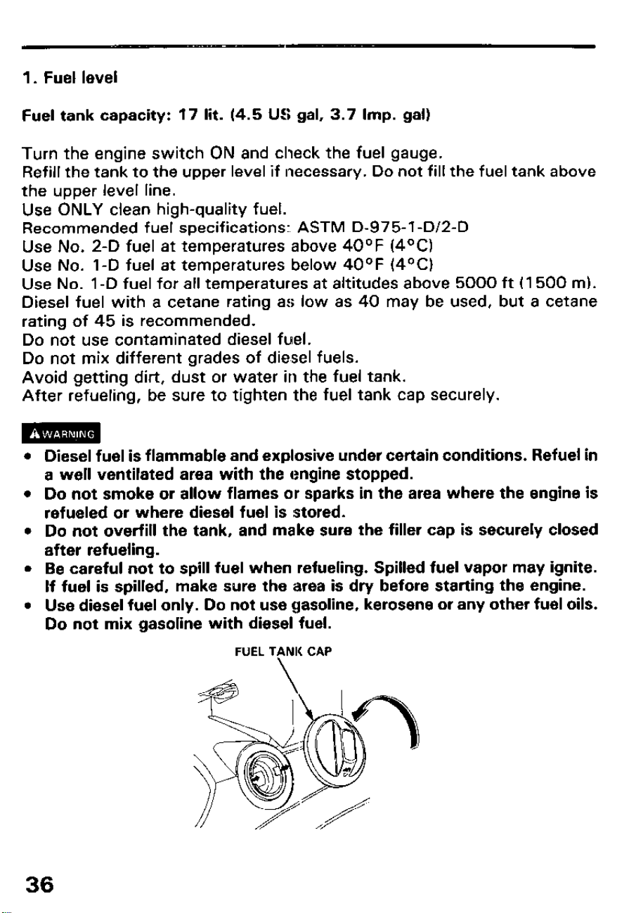
1. Fuel level
Fuel tank capacity: 17 lit. (4.5 US gal, 3.7 Imp. gal)
Turn the engine switch ON and check the fuel gauge.
Refill the tank to the upper level if necessary. Do not fill the fuel tank above
the upper level line.
Use ONLY clean high-quality fuel.
Recommended fuel specifications: ASTM D-975-1-D/2-D
Use No. 2-D fuel at temperatures above 40°F (4OC)
Use No. 1-D fuel at temperatures below 40°F (4OC)
Use No. 1 -D fuel for all temperatures at altitudes above 5000 ft (1500 m).
Diesel fuel with a cetane rating as low as 40 may be used, but a cetane
rating of 45 is recommended.
Do not use contaminated diesel fuel.
Do not mix different grades of diesel fuels.
Avoid getting dirt, dust or water in the fuel tank.
After refueling, be sure to tighten the fuel tank cap securely.
l Diesel fuel is flammable and explosive under certain conditions. Refuel in
a well ventilated area with the engine stopped.
l Do not smoke or allow flames or sparks in the area where the engine is
refueled or where diesel fuel is stored.
l Do not overfill the tank, and make sure the filler cap is securely closed
after refueling.
l Be careful not to spill fuel when refueling. Spilled fuel vapor may ignite.
If fuel is spilled, make sure the area is dry before starting the engine.
l Use diesel fuel only. Do not use gasoline, kerosene or any other fuel oils.
Do not mix gasoline with diesel fuel.
FUEL TANK CAP
36
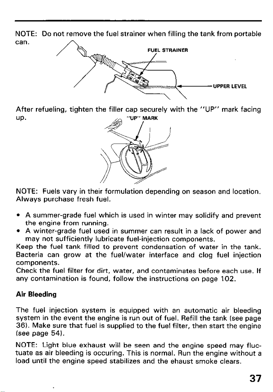
NOTE: Do not remove the fuel strainer when filling the tank from portable
can.
UPPER LEVEL
After refueling, tighten the filler cap securely with the “UP” mark facing
up.
NOTE: Fuels vary in their formulation depending on season and location.
Always purchase fresh fuel.
l A summer-grade fuel which is used in winter may solidify and prevent
the engine from running.
l A winter-grade fuel used in summer can result in a lack of power and
may not sufficiently lubricate fuel-injection components.
Keep the fuel tank filled to prevent condensation of water in the tank.
Bacteria can grow at the fuel/water interface and clog fuel injection
components.
Check the fuel filter for dirt, water, and contaminates before each use. If
any contamination is found, follow the instructions on page 102.
Air Bleeding
The fuel injection system is equipped with an automatic air bleeding
system in the event the engine is run out of fuel. Refill the tank (see page
36). Make sure that fuel is supplied to the fuel filter, then start the engine
(see page 54).
NOTE: Light blue exhaust will be seen and the engine speed may fluc-
tuate as air bleeding is occuring. This is normal. Run the engine without a
load until the engine speed stabilizes and the ehaust smoke clears.
37
2. Tires/wheels
l Check the tire pressure with a pressure gauge.
Turf tire pressure: Front ‘1.55 kg/cm2 (22 psi)
Rear ‘1.41 kg/cm2 (20 psi)
AG tire pressure:
Front 2.11 kg/cm2 (30 psi)
Rear ‘I .41 kg/cm2 (20 psi)
High float tire pressure: Front ‘I. 12 kg/cm2 (16 psi)
Rear ‘I .97 kg/cm2 (28 psi)
l Check that the lug nuts and bolts on each wheel are securely tightened.
Torque: Front wheel 13 kg-m (94 ft-lb)
Rear wheel 18.5 kg-m (134 ft-lb)
piEiq
l Every day, check the lug nuts and bolts daily for security for the first 20
hours of operation, and retighten if necessary. Thereafter, re-check and
retighten them every 50 hours.
l The tire might come off the rirn if the air pressure is too low. Loose
wheel nuts and bolts might cause the wheel to drop off.
l Check side wall and tread surface of each tire for cracks, damage, or
excessive wear.
38
UNDER-HOOD CHECKS
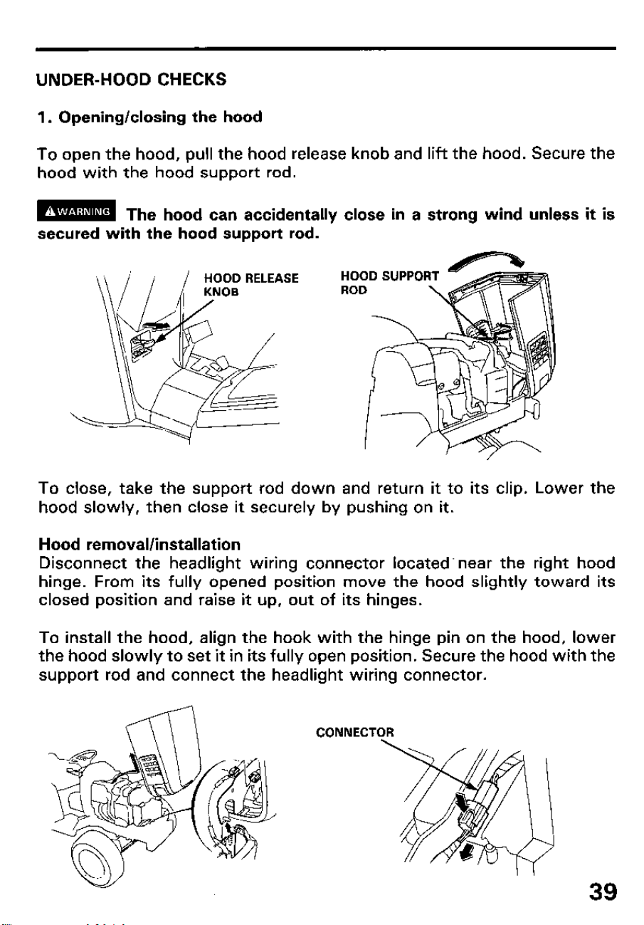
1. Opening/closing the hood
To open the hood, pull the hood release knob and lift the hood. Secure the
hood with the hood support rod.
m
The hood can accidentally close in a strong wind unless it is
secured with the hood support rod.
HOOD SUPPO
To close, take the support rod down and return it to its clip. Lower the
hood slowly, then close it securely by pushing on it.
Hood removal/installation
Disconnect the headlight wiring connector located. near the right hood
hinge. From its fully opened position move the hood slightly toward its
closed position and raise it up, out of its hinges.
To install the hood, align the hook with the hinge pin on the hood, lower
the hood slowly to set it in its fully open position. Secure the hood with the
support rod and connect the headlight wiring connector.
CONNECT
39
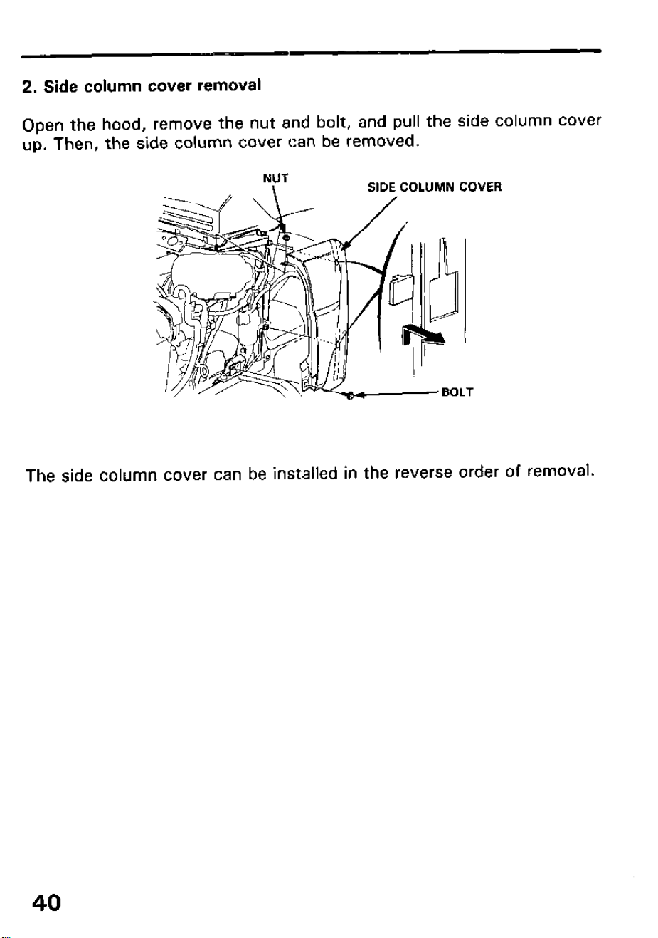
2. Side column cover removal
Open the hood, remove the nut and bolt, and pull the side column cover
up. Then, the side column cover can be removed.
NUT
\
SIDE COLUMN
COVER
The side column cover can be installed in the reverse order of removal.
40
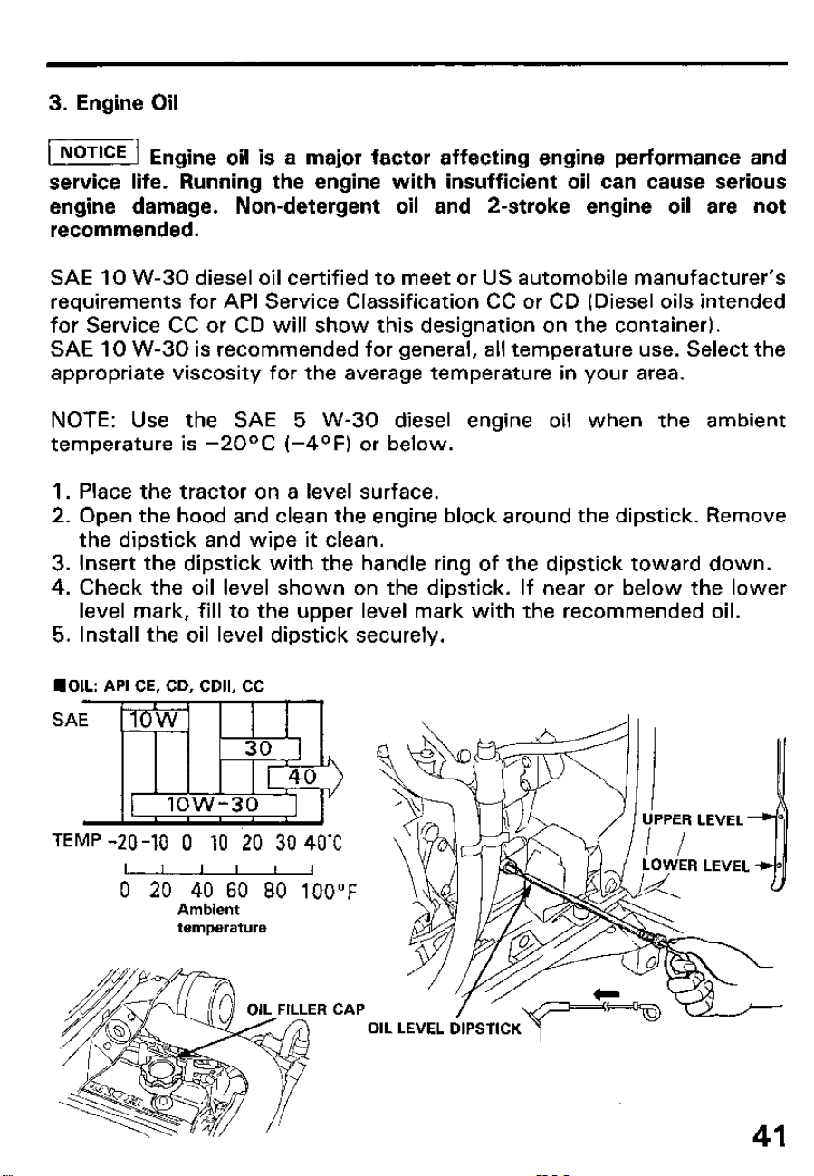
3. Engine Oil
@!%!%I Engine oil is a major factor affecting engine performance and
service life. Running the engine with insufficient oil can cause serious
engine damage. Non-detergent oil and 2-stroke engine oil are not
recommended.
SAE 10 W-30 diesel oil certified to meet or US automobile manufacturer’s
requirements for API Service Classification CC or CD (Diesel oils intended
for Service CC or CD will show this designation on the container).
SAE 10 W-30 is recommended for general, all temperature use. Select the
appropriate viscosity for the average temperature in your area.
NOTE: Use the SAE 5 W-30 diesel engine oil when the ambient
temperature is -2OOC (-4OF) or below.
1. Place the tractor on a level surface.
2. Open the hood and clean the engine block around the dipstick. Remove
the dipstick and wipe it clean.
3. Insert the dipstick with the handle ring of the dipstick toward down.
4. Check the oil level shown on the dipstick. If near or below the lower
level mark, fill to the upper level mark with the recommended oil.
5. Install the oil level dipstick securely.
n OIL: API CE, CD, CDII, CC
I 1 -
SAE 1OW
30 1
[ 40
[ low-30
I
TEMP -20 -10 0 10 20 30 40-C
I I
I I
I ,
0 20 40 60 80 100°F
Ambient
temperature
OIL FILLER CAP
41
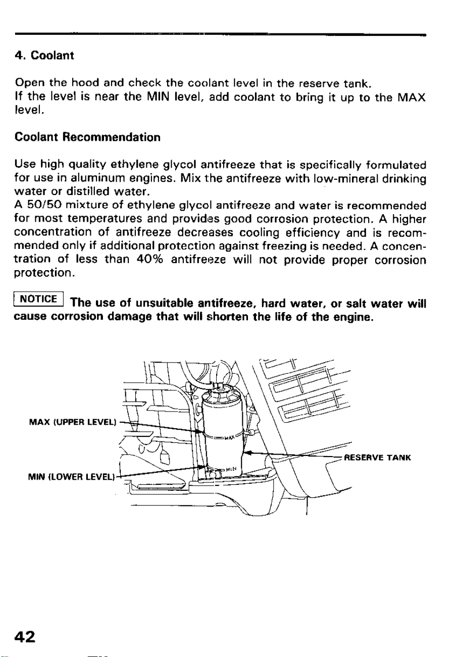
4. Coolant
Open the hood and check the coolant level in the reserve tank.
If the level is near the MIN level, add coolant to bring it up to the MAX
level.
Coolant Recommendation
Use high quality ethylene glycol antifreeze that is specifically formulated
for use in aluminum engines. Mix the antifreeze with low-mineral drinking
water or distilled water.
A 50/50 mixture of ethylene glycol antifreeze and water is recommended
for most temperatures and provides good corrosion protection. A higher
concentration of antifreeze decreases cooling efficiency and is recom-
mended only if additional protection against freezing is needed. A concen-
tration of less than 40% antifreeze will not provide proper corrosion
protection.
1 NOTICE 1 Th
e use of unsuitable antifreeze, hard water, or salt water will
cause corrosion damage that will shorten the life of the engine.
MAX (UPPER LEVEL)
MIN (LOWER
\
\
TANK
42
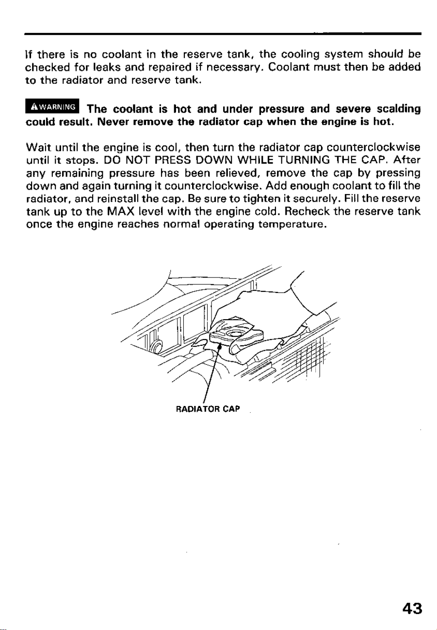
If there is no coolant in the reserve tank, the cooling system should be
checked for leaks and repaired if necessary. Coolant must then be added
to the radiator and reserve tank.
m
The coolant is hot and under pressure and severe scalding
could result. Never remove the radiator cap when the engine is hot.
Wait until the engine is cool, then turn the radiator cap counterclockwise
until it stops. DO NOT PRESS DOWN WHILE TURNING THE CAP. After
any remaining pressure has been relieved, remove the cap by pressing
down and again turning it counterclockwise. Add enough coolant to fill the
radiator, and reinstall the cap. Be sure to tighten it securely. Fill the reserve
tank up to the MAX level with the engine cold. Recheck the reserve tank
once the engine reaches normal operating temperature.
RADlAiOR CAP
43
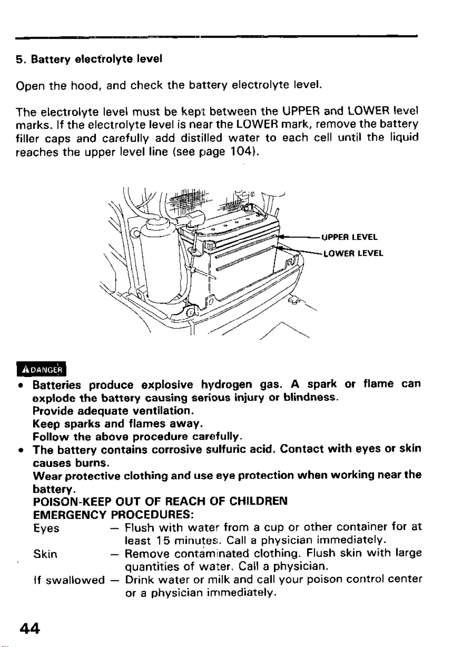
5. Battery electrolyte level
Open the hood, and check the battery electrolyte level.
The electrolyte level must be kept between the UPPER and LOWER level
marks. If the electrolyte level is near the LOWER mark, remove the battery
filler caps and carefully add distilled water to each cell until the liquid
reaches the upper level line (see page 104).
UPPER LEVEL
LOWER LEVEL
l Batteries produce explosive hydrogen gas. A spark or flame can
explode the battery causing serious injury or blindness.
Provide adequate ventilation.
Keep sparks and flames away.
Follow the above procedure carefully.
l The battery contains corrosive sulfuric acid. Contact with eyes or skin
causes burns.
Wear protective clothing and use eye protection when working near the
battery.
POISON-KEEP OUT OF REACH OF CHILDREN
EMERGENCY PROCEDURES:
Eyes
-
Flush with water from a cup or other container for at
least 15 minutes. Call a physician immediately.
Skin
-
Remove contaminated clothing. Flush skin with large
quantities of water. Call a physician.
If swallowed - Drink water or milk and call your poison control center
or a physician immediately.
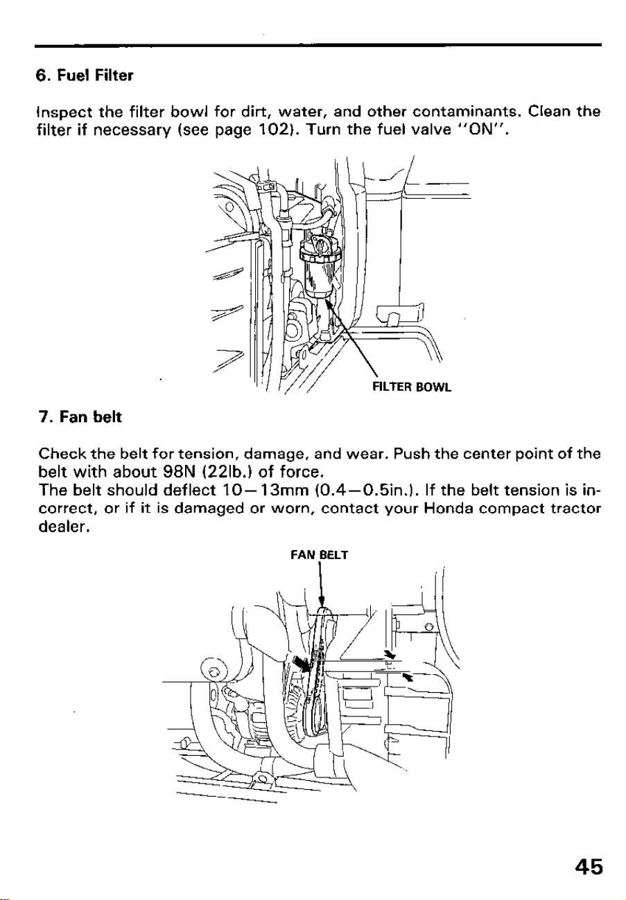
6. Fuel Filter
Inspect the filter bowl for dirt, water, and other contaminants. Clean the
filter if necessary (see page 102). Turn the fuel valve “ON”.
7. Fan belt
Check the belt for tension, damage, and wear. Push the center point of the
belt with about 98N (22lb.I of force.
The belt should deflect lo- 13mm (0.4-0.5in.j. If the belt tension is in-
correct, or if it is damaged or worn, contact your Honda compact tractor
dealer.
FAN BELT
45
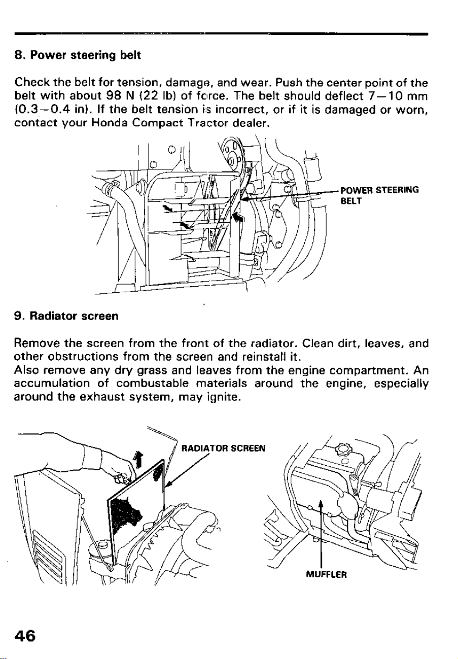
8. Power steering belt
Check the belt for tension, damage, and wear. Push the center point of the
belt with about 98 N (22 lb) of force. The belt should deflect 7- 10 mm
(0.3-0.4 in). If the belt tension is incorrect, or if it is damaged or worn,
contact your Honda Compact Tractor dealer.
POWER
BELT
STEERING
9. Radiator screen
Remove the screen from the front of the radiator. Clean dirt, leaves, and
other obstructions from the screen and reinstall it.
Also remove any dry grass and leaves from the engine compartment. An
accumulation of combustable materials around the engine, especially
around the exhaust system, may ignite.
RADIATOR SCREEN
MUFFLER
46
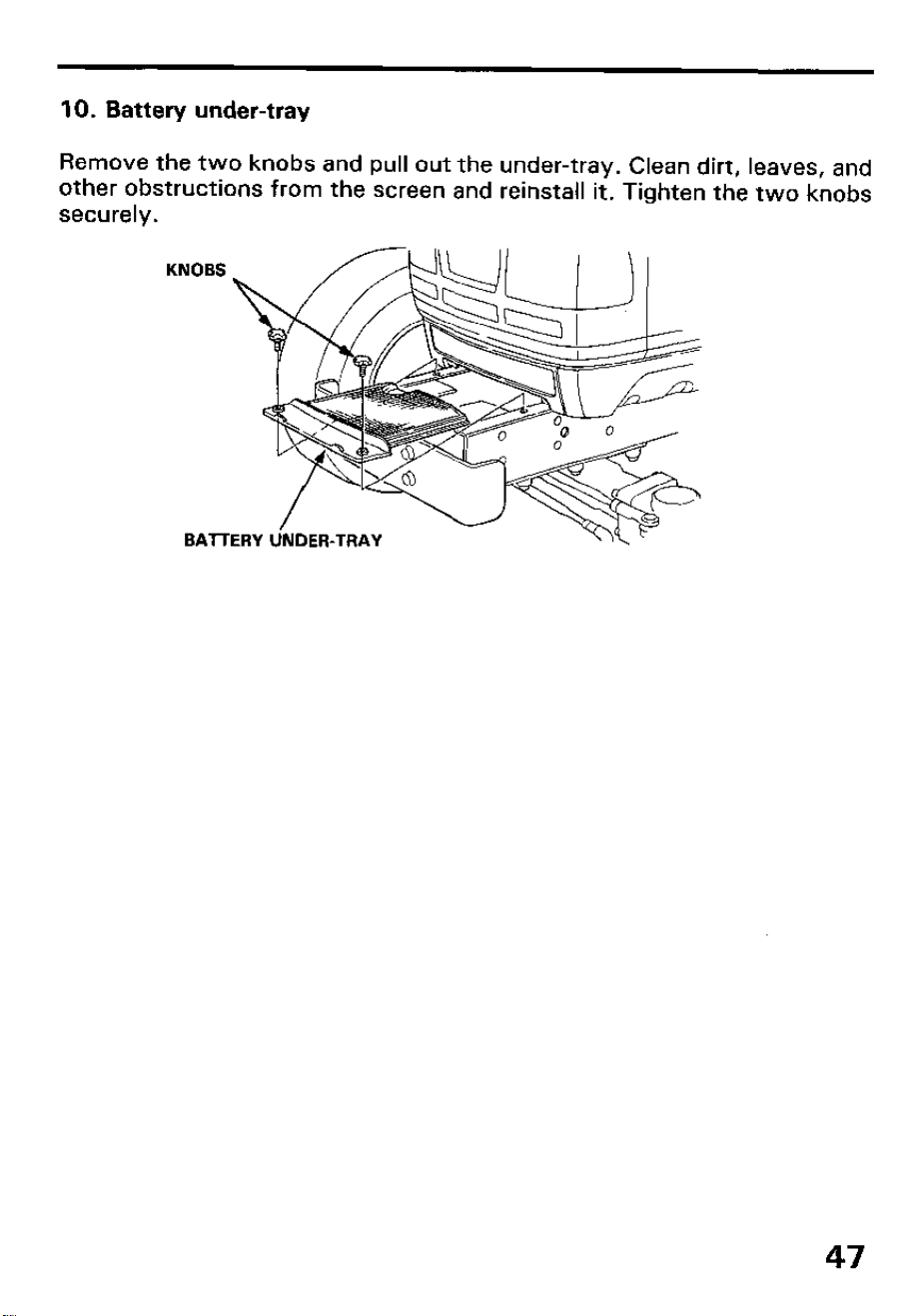
10. Battery under-tray
Remove the two knobs and pull out the under-tray. Clean dirt, leaves, and
other obstructions from the screen and reinstall it. Tighten the two knobs
securely.
47
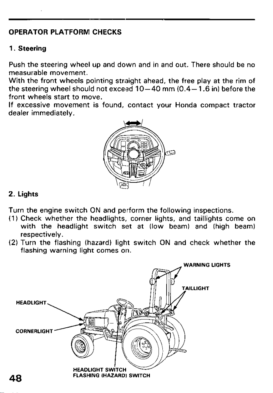
OPERATOR PLATFORM CHECKS
1. Steering
Push the steering wheel up and down and in and out. There should be no
measurable movement.
With the front wheels pointing straight ahead, the free play at the rim of
the steering wheel should not exceed 1 O-40 mm (0.4- 1.6 in) before the
front wheels start to move.
If excessive movement is found, contact your Honda compact tractor
dealer immediately.
2. 1
.ights
Turn the engine switch ON and perform the following inspections.
(1) Check whether the headlights, corner lights, and taillights come on
with the headlight switch set at (low beam) and (high beam)
respectively.
(2) Turn the flashing (hazard) light switch ON and check whether the
flashing warning light comes on.
HEADLIGHT
CORNERLIGHT
LIGHTS
48
FLASHING (HAZARD) SWITCH
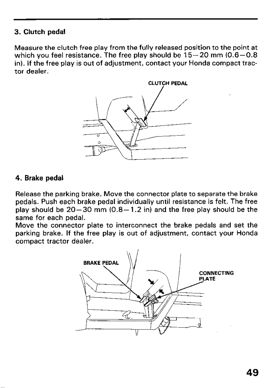
3. Clutch pedal
Measure the clutch free play from the fully released position to the point at
which you feel resistance. The free play should be 15-20 mm (0.6-0.8
in). If the free play is out of adjustment, contact your Honda compact trac-
tor dealer.
CLUTCH PEDAL
4. Brake pedal
Release the parking brake. Move the connector plate to separate the brake
pedals. Push each brake pedal individually until resistance is felt. The free
play should be 20-30 mm (0.8- 1.2 in) and the free play should be the
same for each pedal.
Move the connector plate to interconnect the brake pedals and set the
parking brake. If the free play is out of adjustment, contact your Honda
compact tractor dealer.
CTING
49
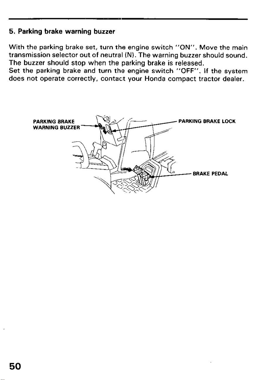
5. Parking brake warning buzzer
With the parking brake set, turn the engine switch “ON”. Move the main
transmission selector out of neutral (N). The warning buzzer should sound.
The buzzer should stop when the parking brake is released.
Set the parking brake and turn the engine switch “OFF”. If the system
does not operate correctly, contac:t your Honda compact tractor dealer.
PARKING BRAKE
WARNING BUZZER -
PARKING BRAKE LOCK
- BRAKE PEDAL
50
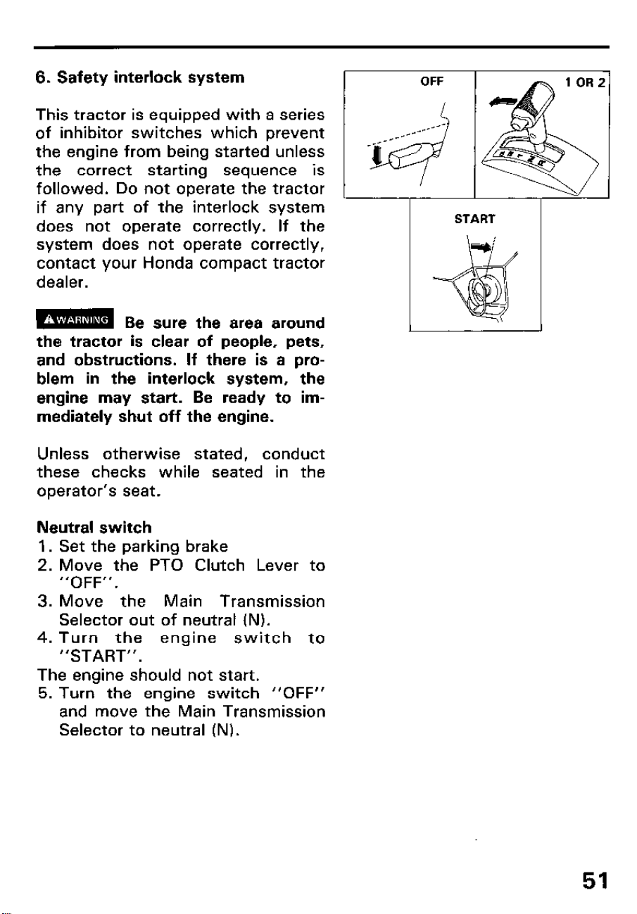
6. Safety interlock system
This tractor is equipped with a series
of inhibitor switches which prevent
the engine from being started unless
the correct starting sequence is
followed. Do not operate the tractor
if any part of the interlock system
does not operate correctly. If the
system does not operate correctly,
contact your Honda compact tractor
dealer.
the tractor is clear of people, pets,
and obstructions. If there is a pro-
blem in the interlock system, the
engine may start. Be ready to im-
mediately shut off the engine.
Unless otherwise stated, conduct
these checks while seated in the
operator’s seat.
Neutral switch
1. Set the parking brake
2. Move the PTO Clutch Lever to
“OFF”.
3. Move the Main Transmission
Selector out of neutral (N).
4. Turn the engine switch to
“START”.
The engine should not start.
5. Turn the engine switch “OFF”
and move the Main Transmission
Selector to neutral (N).
51
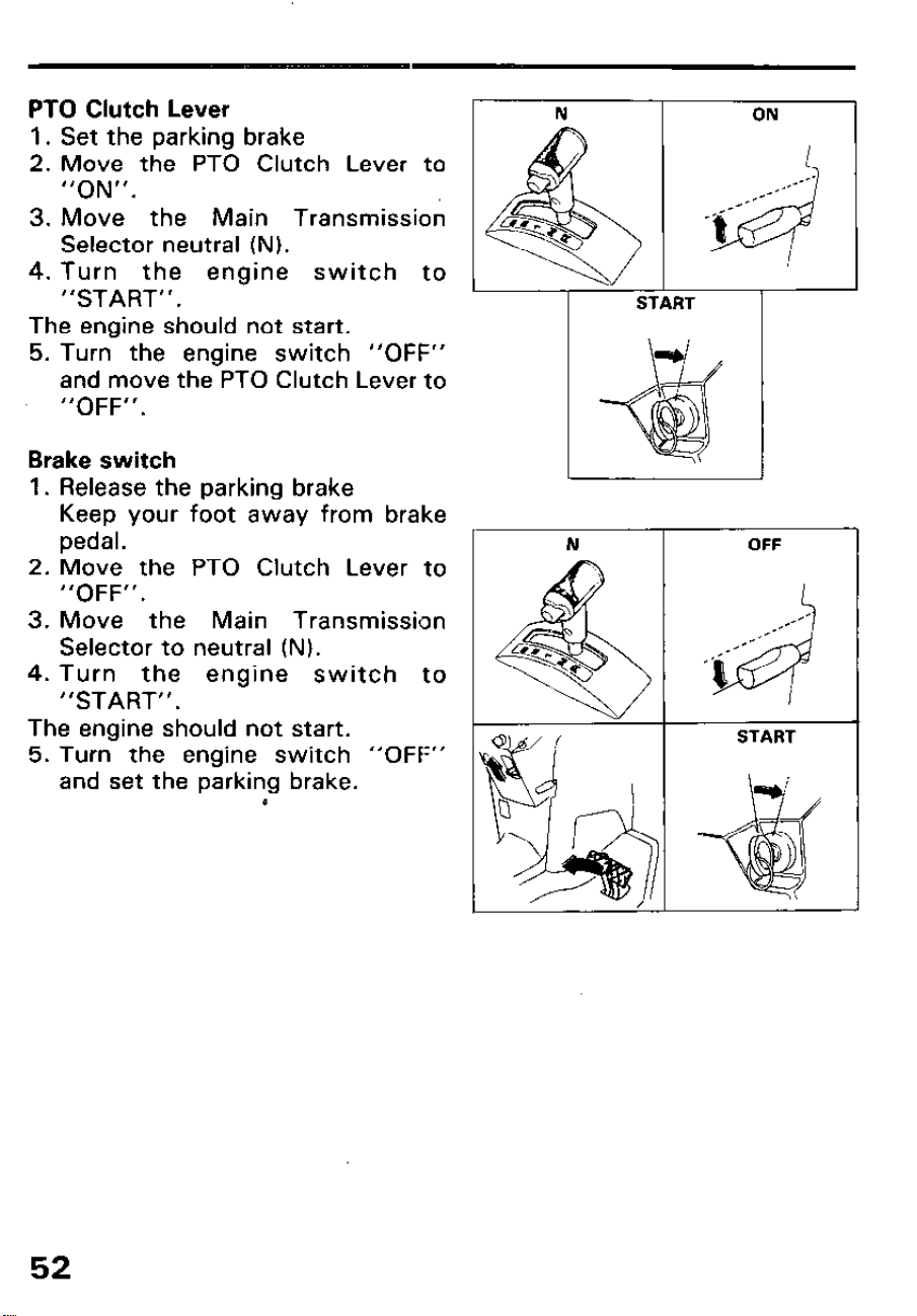
PTO Clutch Lever
1. Set the parking brake
2. Move the PTO Clutch Lever to
“ON”.
3. Move the Main Transmission
Selector neutral (N).
4. Turn the engine switch to
“START”.
The engine should not start.
5. Turn the engine switch “OFF”
and move the PTO Clutch Lever to
“OFF”.
Brake switch
1.
2.
3.
4.
Release the parking brake
Keep your foot away from brake
pedal.
Move the PTO Clutch Lever to
“OFF”.
Move the Main Transmission
Selector to neutral (N).
Turn the engine switch to
“START”.
The engine should not start.
5. Turn the engine switch “OFF”
and set the parking brake.
I
52
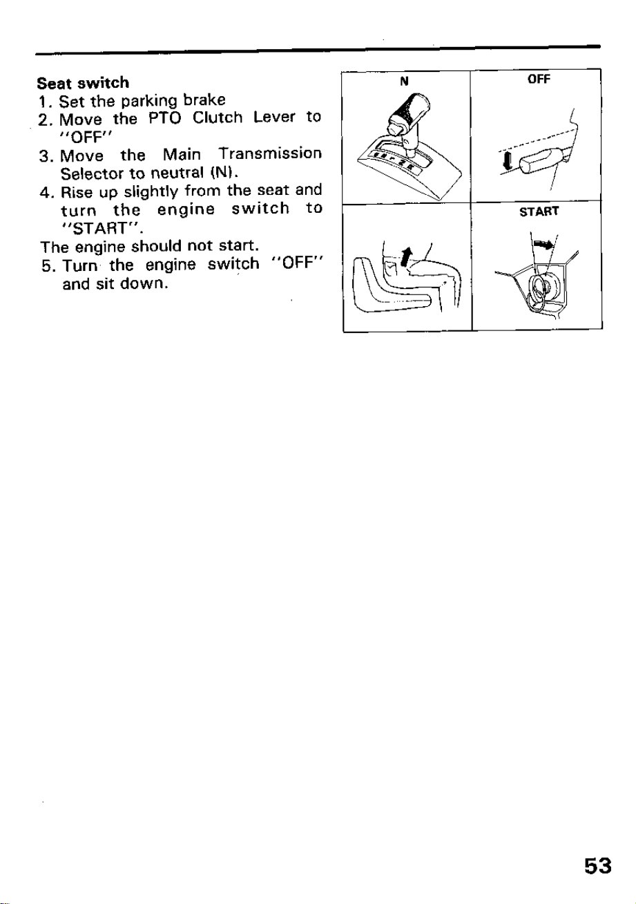
Seat switch
1. Set the parking brake
2. Move the PTO Clutch Lever to
“OFF”
3. Move the Main Transmission
Selector to neutral (N).
4. Rise up slightly from the seat and
turn the engine switch to
“START”.
The engine should not start.
5. Turn the engine switch “OFF”
and sit down.
53
6. OPERATION
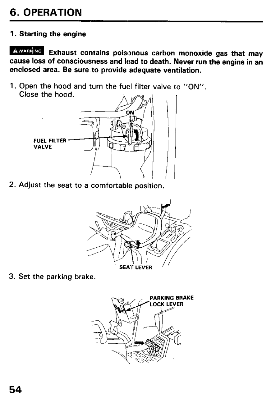
1. Starting the engine
m
Exhaust contains poisonous carbon monoxide gas that may
cause loss of consciousness and lead to death. Never run the engine in an
enclosed area. Be sure to provide adequate ventilation.
1.
Open the hood and turn the fuel filter valve
Close the hood.
-----&~ll I
to “ON”.
2. Adjust the seat to a comfortable position.
3. Set the parking brake.
54
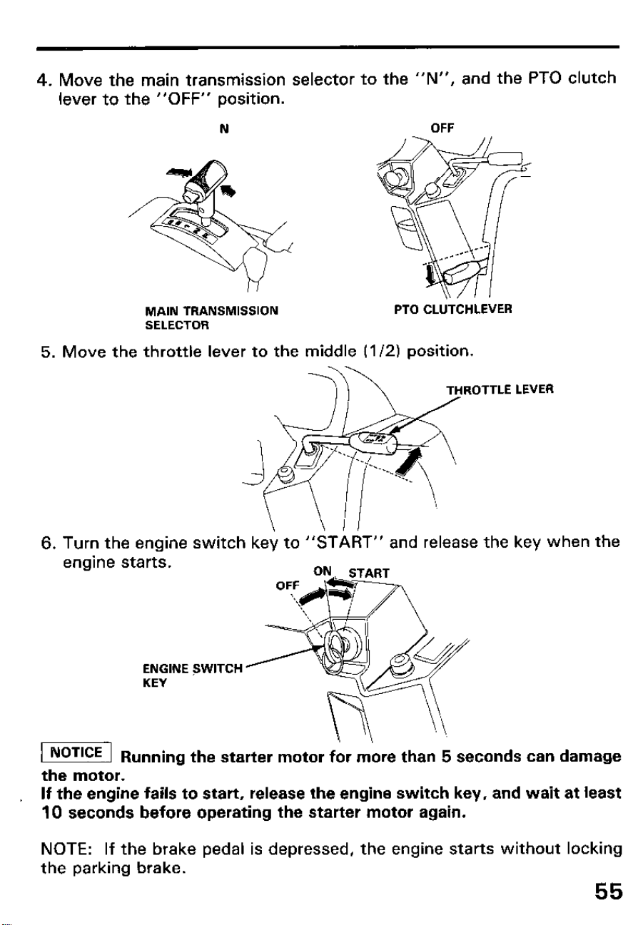
4. Move the main transmission selector to the “N”, and the PTO clutch
lever to the “OFF” position.
N
MAIN TRANSMISSION
SELECTOR
PTO CLtiTCHLEVER
5. Move the throttle lever to the middle (l/2) position.
6. Turn the engine switch key to “START” and release the key when the
engine starts.
ENGINE FWITCH ’
KEY
-1
\
Ru
nning the starter motor for more than 5 seconds can damage
the motor.
, If the engine fails to start, release the engine switch key, and wait at least
10 seconds before operating the starter motor again.
NOTE: If the brake pedal is depressed, the engine starts without locking
the parking brake.
55
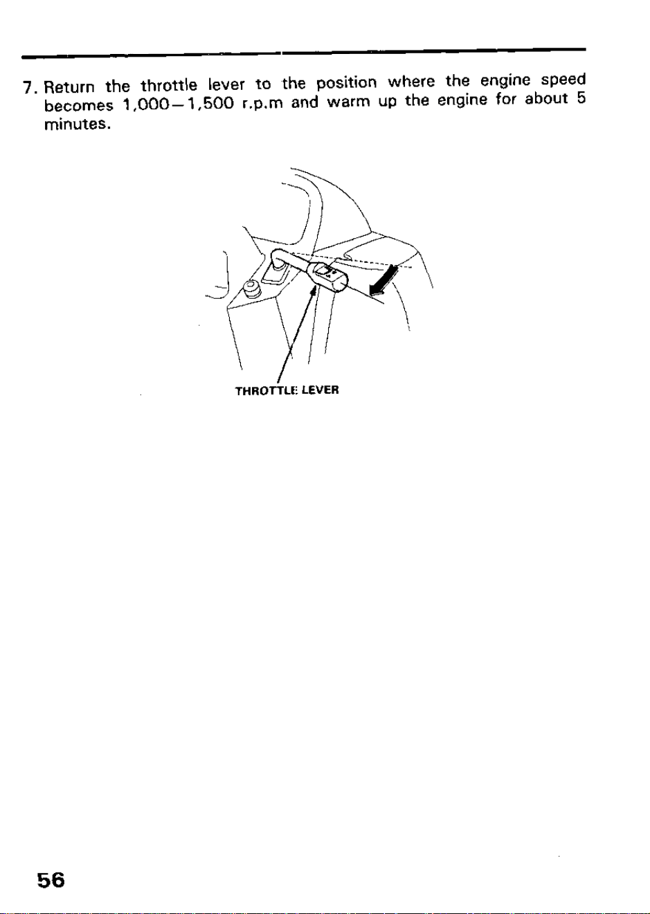
7. Return the throttle lever to the position where the engine speed
becomes 1,000-l ,500 r.p.m and warm up the engine for about 5
minutes.
-\
J
,
.ib
--- --__
-----__ ___
&@
v
- 0
\
\,,
THROTiLti LEVER
56
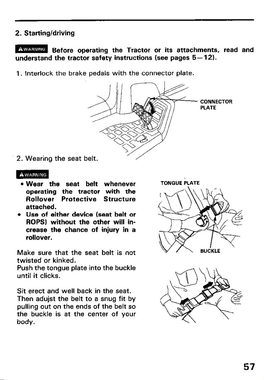
2. Starting/driving
m
Before operating the Tractor or its attachments, read and
understand the tractor safety instructions (see pages 5- 12).
1. Interlock the brake pedals with the connector plate.
CONNECTOR
PLATE
2. Wearing the seat belt.
‘/
m
l Wear the seat belt whenever
operating the tractor with the
Rollover Protective Structure
attached.
Use of either device (seat belt or
ROPS) without the other will in-
crease the chance of injury in a
rollover.
Make sure that the seat belt is not
twisted or kinked.
Push the tongue plate into the buckle
until it clicks.
Sit erect and well back in the seat.
Then adujst the belt to a snug fit by
pulling out on the ends of the belt so
the buckle is at the center of your
body.
TONGUE PLATE
57
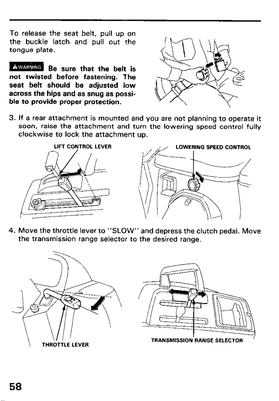
To release the seat belt, pull up on
the buckle latch and pull out the
tongue plate.
m
Be sure that the belt is
not twisted before fastening. The
seat belt should be adjusted low
across the hips and as snug as possi-
ble to provide proper protection.
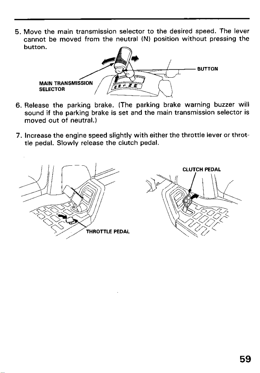
3.
4.
If a rear attachment is mounted and you are not planning to operate it
soon, raise the attachment and turn the lowering speed control fully
clockwise to lock the attachment up.
LIFT CONTROL LEVER
LOWERING SPEED CONTROL
Move the throttle lever to “SLOW” and depress the clutch pedal. Move
the transmission range selector to the desired range.
58
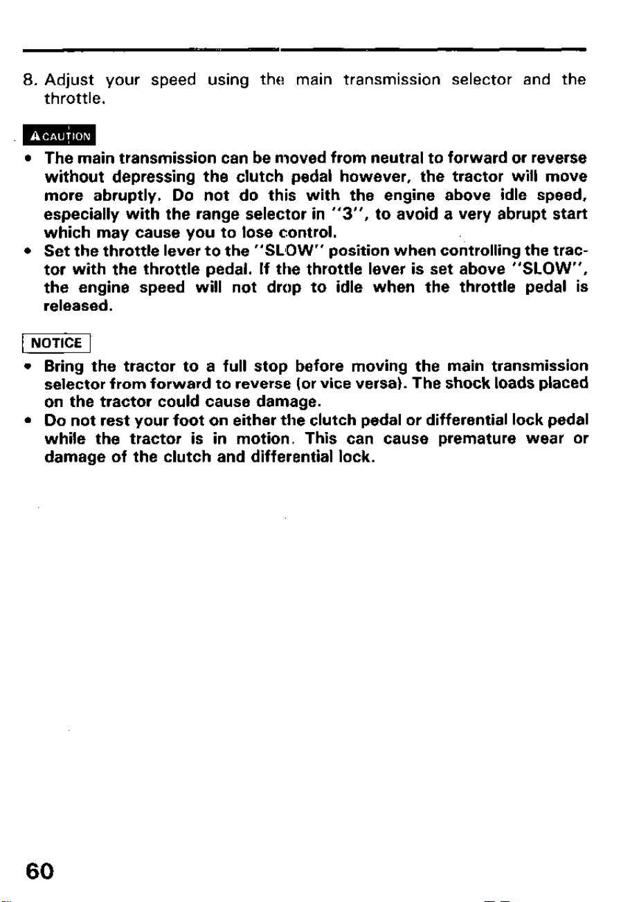
5. Move the main transmission selector to the desired speed. The lever
cannot be moved from the neutral (N) position without pressing the
button.
BUTTON
MAIN TRANSMI
SELECTOR
6. Release the parking brake. (The parking brake warning buzzer will
sound if the parking brake is set and the main transmission selector is
moved out of neutral.)
7. Increase the engine speed slightly with either the throttle lever or throt-
tle pedal. Slowly release the clutch pedal.
HROTTLE PEDAL
59
8. Adjust your speed using the main transmission selector and the
throttle.
l The main transmission can be moved from neutral to forward or reverse
without depressing the clutch pedal however, the tractor will move
more abruptly. Do not do this with the engine above idle speed,
especially with the range selector in “3”, to avoid a very abrupt start
which may cause you to lose control.
l Set the throttle lever to the “SLIOW” position when controlling the trac-
tor with the throttle pedal. If the throttle lever is set above “SLOW”,
the engine speed will not drop to idle when the throttle pedal is
released.
1 NOTICE 1
l Bring the tractor to a full stop before moving the main transmission
selector from forward to reverse (or vice versa). The shock loads placed
on the tractor could cause damage.
l Do not rest your foot on either the clutch pedal or differential lock pedal
while the tractor is in motion. This can cause premature wear or
damage of the clutch and differential lock.
60
3. Warm up and break in operation
Warm up
Let the tractor warm up for about 5 minutes after starting. This allows the
engine, transmission, hydraulic, and power steering fluids and com-
ponents to come up to normal operating temperature. Operating a “cold”
tractor may cause premature wear of components.
Break in
Your Honda compact tractor has been carefully built and tested, but
special care taken during its first 50 hours of operation will greatly extend
its service life.
l Allow the tractor to fully warm up before operating it.
l Avoid sudden starts and stops.
l Avoid operating the engine at full speed or full load.
Hydraulic lift
If an attachment is mounted, check the lift system operation while the
tractor is warming up.
Cycle the attachment up and down to check for smooth operation. Check
the lowering speed and adjust if necessary.
61
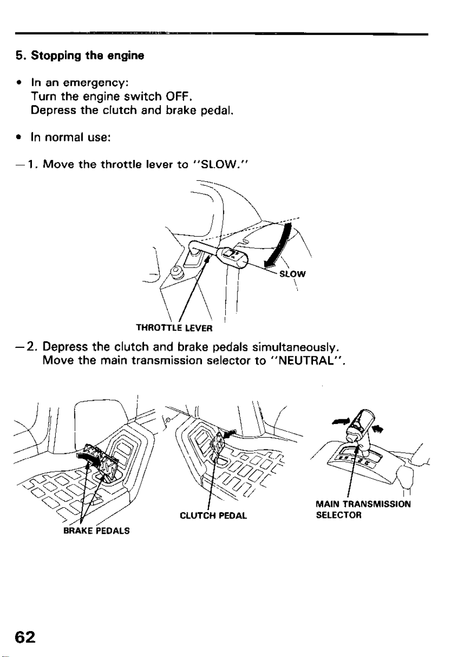
5. Stopping the engine
l In an emergency:
Turn the engine switch OFF.
Depress the clutch and brake pedal.
l In normal use:
-1. Move the throttle lever to “SLOW.”
-2.
THROTTLE LEVER
Depress the clutch and brake pedals simultaneously.
Move the main transmission selector to “NEUTRAL”.
f3hcE ~DALS
62
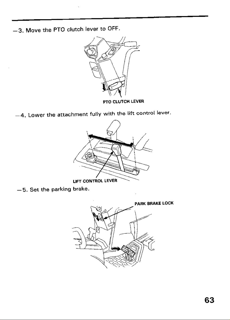
-3. Move the PTO clutch lever to OFF.
PTO CLUTCH LEVER
-4. Lower the attachment fully with the lift control lever.
-5. Set the parking
brake.
PARK BRAKE LOCK
63
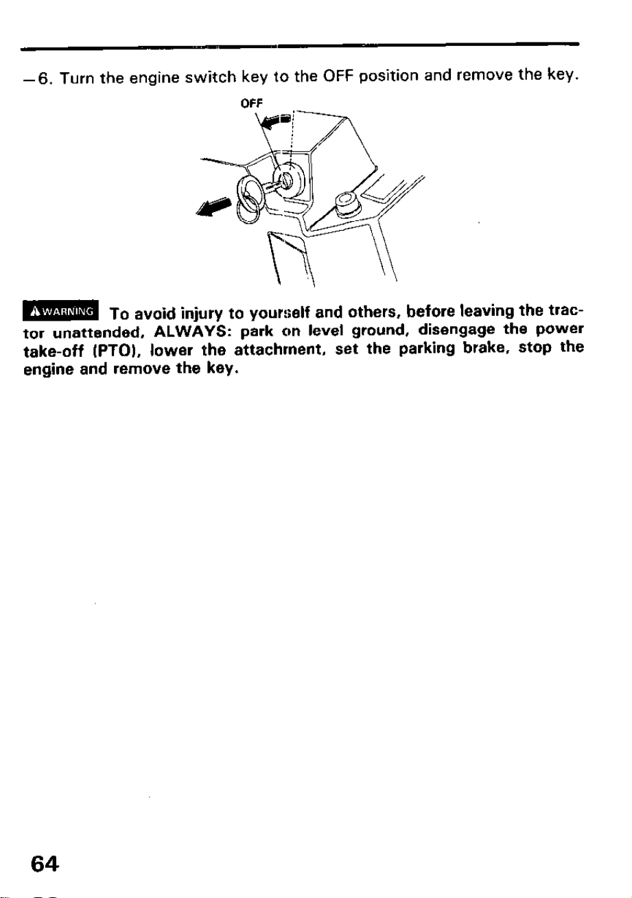
-6. Turn the engine switch key to the OFF position and remove the key.
OFF
m
To avoid injury to yourself and others, before leaving the trac-
tor unattended, ALWAYS: park on level ground, disengage the power
take-off (PTO), lower the attachment, set the parking brake, stop the
engine and remove the key.
64
6. Turning
m
Turning the tractor at excessive speed especially on uneven ter-
rain can cause the tractor to tip over and you can be injured. Slow down
before turning.
To prevent accidental tip over:
l Never make abrupt starts while the wheels are turned.
l Slow down before making sharp and/or hard turns.
l Avoid sharp turns in rutty or uneven terrain.
l Connect the right and left brake pedals with the connector plate except
when making a tight turn by depressing one brake pedal.
l Engaging the differential lock while making sharp turns can cause you to
lose steering control.
l Be sure to raise ground engaging attachments (rotary tillers, disk har-
rows, moldboard plows, etc.), before executing sharp turns. If the at-
tachment is not raised, you can damage the tractor and/or the
attachment.
l Rear attachments swing out in a larger arc than the tractor, and can
strike nearby objects.
l Use care when turning the tractor near a wall or other obstructions
when a rear mounted attachment is being used.
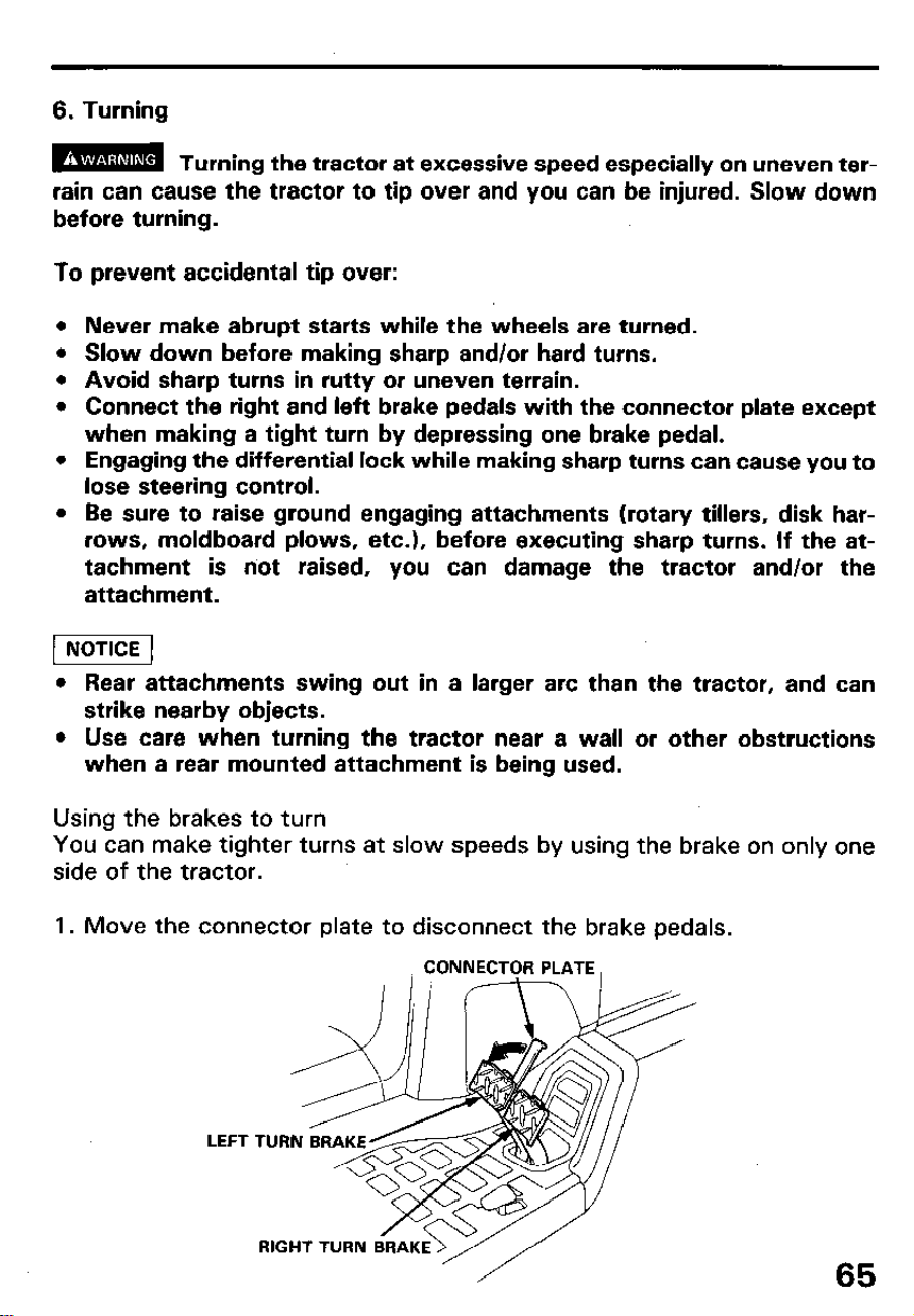
Using the brakes to turn
You can make tighter turns at slow speeds by using the brake on only one
side of the tractor.
1. Move the connector plate to disconnect the brake pedals.
RIGHT TURN
65

2. Slow the tractor and raise any attachment.
3. While turning the steering wheel, depress the brake pedal on the side of
the direction of the turn. (Left turn: left brake. Right turn: right brake.)
4. Release the brake while returning the steering wheel to a straight-ahead
position.
j-iiGiq Us’
mg the brakes to turrn while on grass will tend to damage the
turf.
66
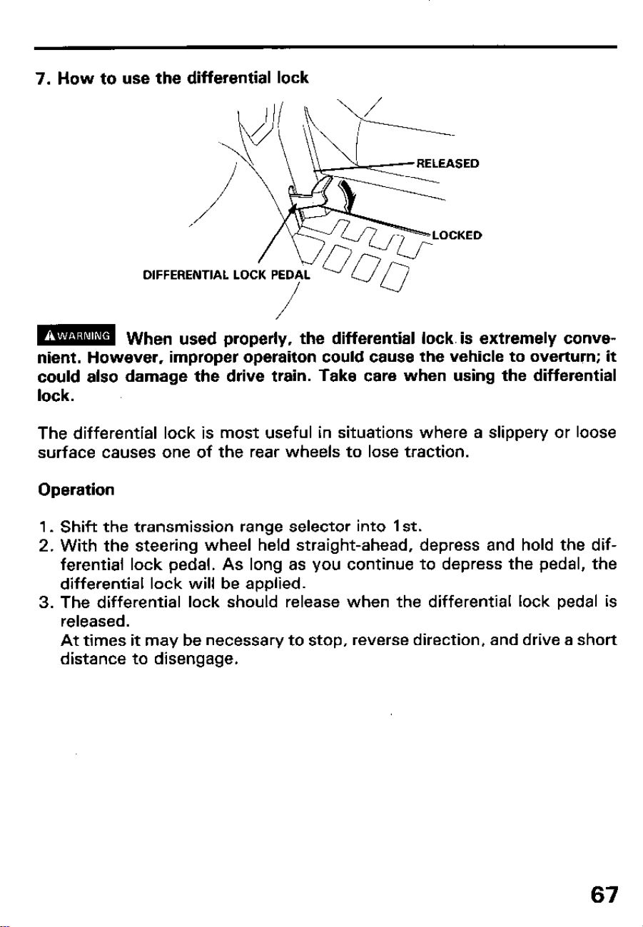
7. How to use the differential lock
DIFFERENTIAL LO
/
m When used properly, the differential lock. is extremely conve-
nient. However, improper operaiton could cause the vehicle to overturn; it
could also damage the drive train. Take care when using the differential
lock.
The differential lock is most useful in situations where a slippery or loose
surface causes one of the rear wheels to lose traction.
Operation
1. Shift the transmission range selector into 1 st.
2. With the steering wheel held straight-ahead, depress and hold the dif-
ferential lock pedal. As long as you continue to depress the pedal, the
differential lock will be applied.
3. The differential lock should release when the differential lock pedal is
released.
At times it may be necessary to stop, reverse direction, and drive a short
distance to disengage.
67
4. To release the differential lock, remove your foot from the lock pedal,
bring the tractor to a full stop, shift the main transmission from FOR-
WARD to REVERSE or vice versa, and drive a short distance.
m
The differential lock must be released before operating the
tractor on hard surfaces or slopes, or while turning. Otherwise the tractor
may overturn, causing severe personal injury.
.
To avoid damage to transmission mechanism.
l Do not apply the differential lock while the wheels are turning.
l Do not rest your foot on the differential lock pedal unless you want to
engage the differential lock.
l Do not apply the brake and the differential lock at the same time.
l Check that the differential lock has been released after you have finish-
ed using it.
l Do not apply the differential lock while driving at high speed.
l Do not apply the differential lock on a hard packed surface.
68
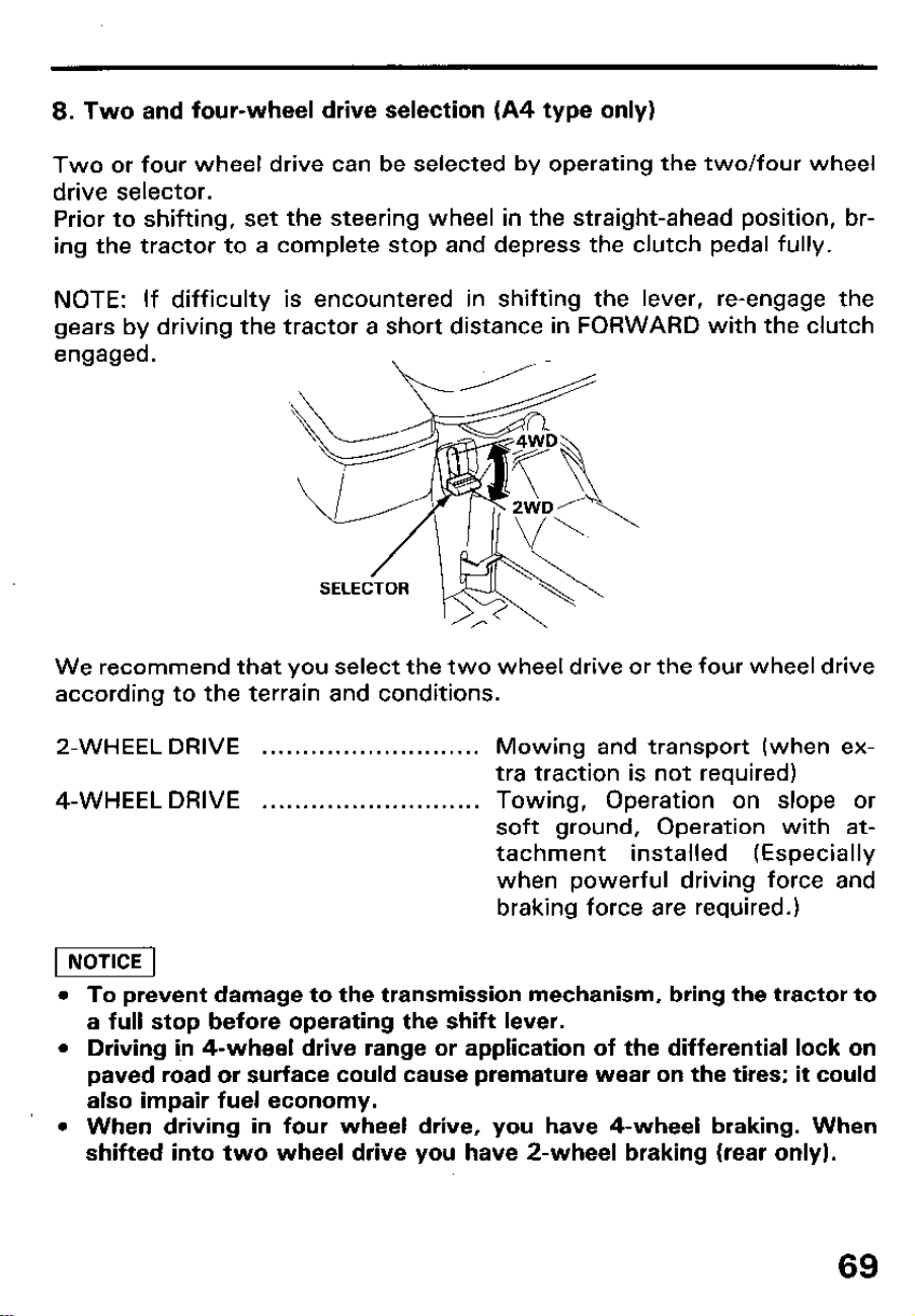
8. Two and four-wheel drive selection (A4 type only)
Two or four wheel drive can be selected by operating the two/four wheel
drive selector.
Prior to shifting, set the steering wheel in the straight-ahead position, br-
ing the tractor to a complete stop and depress the clutch pedal fully.
NOTE: If difficulty is encountered in shifting the lever, re-engage the
gears by driving the tractor a short distance in FORWARD with the clutch
engaged.
We recommend that you select the two wheel drive or the four wheel drive
according to the terrain and conditions.
2-WHEEL DRIVE
. . . . . . . . . . . . . . . . . . . . . . . . . . .
Mowing and transport (when ex-
tra traction is not required)
4-WHEEL DRIVE
. . . . . . . . . . . . . . . . . . . . . . . . . . .
Towing, Operation
on slope or
soft ground, Operation with at-
tachment installed (Especially
when powerful driving force and
braking force are required.)
piEiq
l To prevent damage to the transmission mechanism, bring the tractor to
a full stop before operating the shift lever.
l Driving i,n 4-wheel drive range or application of the differential lock on
paved road or surface could cause premature wear on the tires; it could
also impair fuel economy.
l When driving in four wheel drive, you have 4-wheel braking. When
shifted into two wheel drive you have a-wheel braking (rear only).
69
9. Use of power steering
The power steering system operates only when the engine is running.
Steering effort will increase when the engine is not running.
When you turn the wheel fully left or right, a relief valve will open to
relieve excess pressure. You will hear a high-pitched sound when this
happens. Avoid this condition for prolonged periods to prevent damage
to the steering system. Also avoid using excessive steering force when
the front tires are caught in a furrow or trench to prevent rim and tire
damage and possible tractor upset.
Do not make large movements of the steering wheel when the engine is
not running. Steering fluid will be forced from the system back to the
reservoir and may cause the reservoir to overflow.
70
10. Attachment limitations
The use of Honda HTA attachments is recommended. If an attachment ex-
ceeds the weight limits described below, or if the counterweights used do
not conform to the sizes and weights specified in “Counterweight Table”,
the operator may be hurt or the tractor may be damaged.
Never use attachments which exceed sizes and weights specified.
Never use counterweights other than those specified in Counterweight
Table.
Any malfunction or damage to the tractor is unwarrantable if it is the con-
sequence of use of attachments not specified or recommended by Honda.
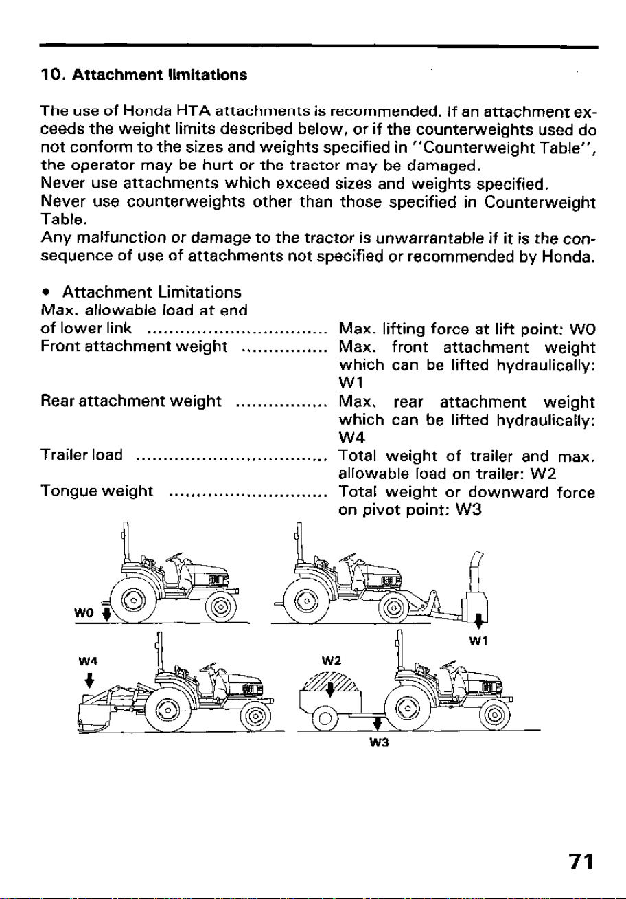
l Attachment Limitations
Max. allowable load at end
of lower link
. . . . . . . . . . . . . . . . . . . . . . . . . . . . . . . . .
Max. lifting force at lift point: WO
Front attachment weight
. . . . . . . . . . . . . . . .
Max. front attachment weight
which can be lifted hydraulically:
Wl
Rear attachment weight
. . . . . . . . . . . . . . . . .
Max.
rear attachment weight
which can be lifted hydraulically:
w4
Trailer load
. . . . . . . . . . . . . . . . . . . . . . . . . . . . . . . . . . .
Total weight of trailer and max.
allowable load on trailer: W2
Tongue weight
. . . . . . . . . . . . . . . . . . . . . . . . . . . . .
Total weight or downward force
on pivot point: W3
71
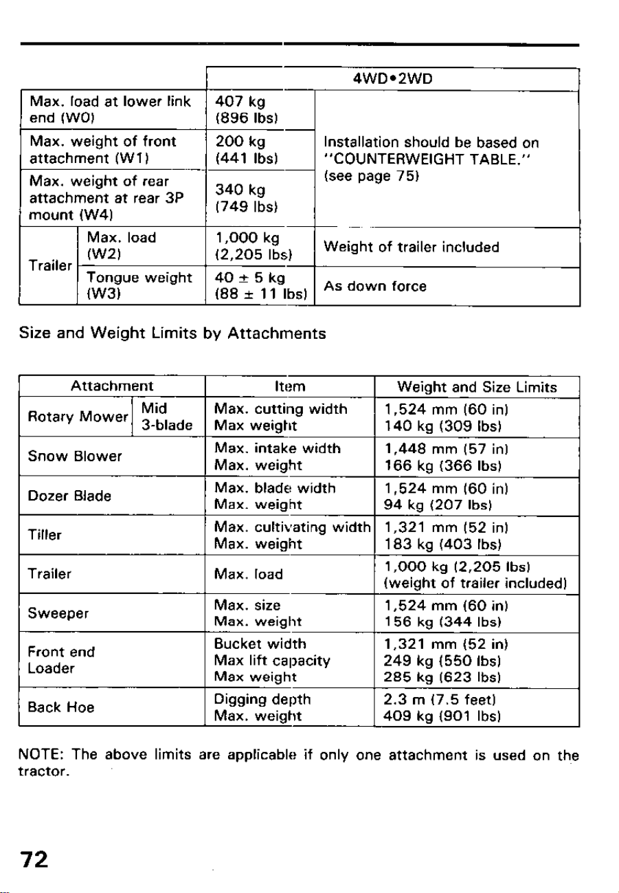
4WDe2WD
1 Max. load at lower link 1 407 kg 1
m-1 “CO”/TERwE,GHT TABLE.”
lnstallatlon should be based on
Size and Weight Limits by Attachments
Attachment
Item
Weight and Size Limits
Mid
Rotary Mower 3-blade
Max. cutting width
1,524 mm (60 in)
Max weight
140 kg (309 Ibs)
Snow Blower
Max. intake width
1,448 mm (57 in)
Max. weight
166 kg (366 Ibs)
Dozer Blade
Max. blade width
1,524 mm (60 in)
Max. weight
94 kg (207 Ibs)
Tiller
Max. cultivating width 1,321 mm (52 in)
Max. weight
183 kg (403 Ibs)
Trailer
Max. load
1,000 kg (2,205 Ibs)
(weight of trailer included)
Sweeper
Max. size
1,524 mm (60 in)
Max. weight
156 kg (344 Ibs)
Front end
Loader
Bucket width
Max lift capacity
Max weight
1,321 mm (52 in)
249 kg (550 Ibs)
285 kg (623 Ibs)
Back Hoe
Digging depth
Max. weight
2.3 m (7.5 feet)
409 kg (901 Ibs)
NOTE: The above limits are applicable if only one attachment is used on th,e
tractor.
72
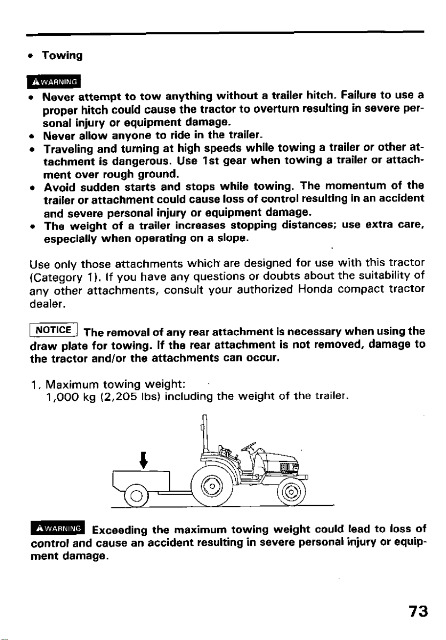
l Towing
m
l Never attempt to tow anything without a trailer hitch. Failure to use a
proper hitch could cause the tractor to overturn resulting in severe per-
sonal injury or equipment damage.
l Never allow anyone to ride in the trailer.
l Traveling and turning at high speeds while towing a trailer or other at-
tachment is dangerous. Use 1st gear when towing a trailer or attach-
ment over rough ground.
l Avoid sudden starts and stops while towing. The momentum of the
trailer or attachment could cause loss of control resulting in an accident
and severe personal injury or equipment damage.
l The weight of a trailer increases stopping distances; use extra care,
especially when operating on a slope.
Use only those attachments which’ are designed for use with this tractor
(Category 1). If you have any questions or doubts about the suitability of
any other attachments, consult your authorized Honda compact tractor
dealer.
I] Th
e removal of any rear attachment is necessary when using the
draw plate for towing. If the rear attachment is not removed, damage to
the tractor and/or the attachments can occur.
1. Maximum towing weight:
1,000 kg (2,205 Ibs) including the weight of the trailer.
m Exceeding the maximum towing weight could lead to loss of
control and cause an accident resulting in severe personal injury or equip-
ment damage.
73
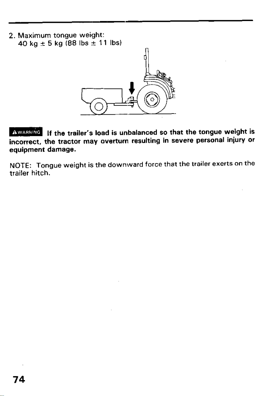
2. Maximum tongue weight:
40 kg k 5 kg (88 Ibs I?I 11 Ibs)
m
If the trailer’s load is unbalanced so that the tongue weight is
incorrect, the tractor may overturn resulting in severe personal injury or
equipment damage.
NOTE:
Tongue weight is the downward force that the trailer exerts on the
trailer hitch.
74
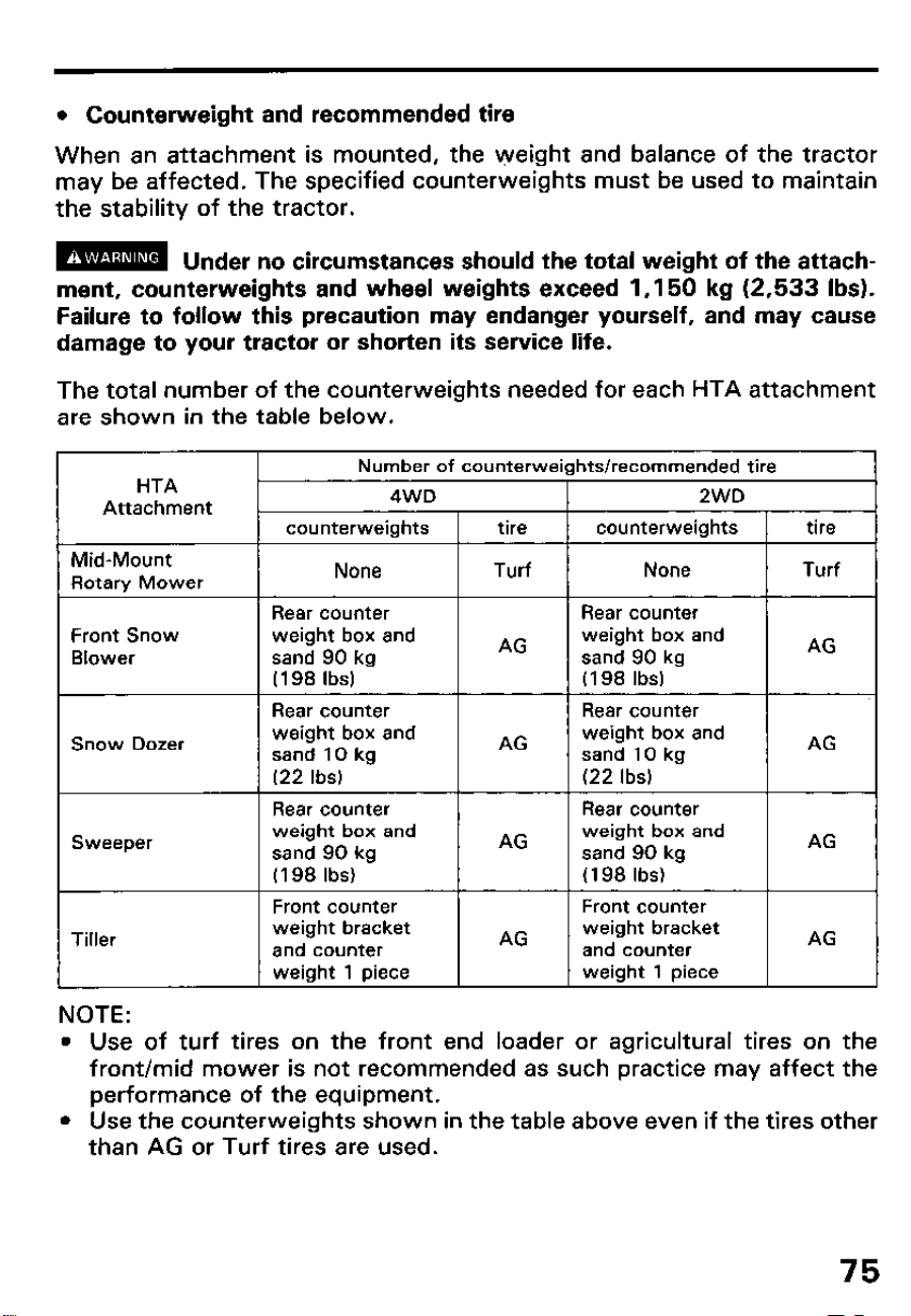
l Counterweight and recommended tire
When an attachment is mounted, the weight and balance of the tractor
may be affected. The specified counterweights must be used to maintain
the stability of the tractor.
m
Under no circumstances should the total weight of the attach-
ment, counterweights and wheel weights exceed 1,150 kg (2,533 Ibs).
Failure to follow this precaution may endanger yourself, and may cause
damage to your tractor or shorten its service life.
The total number of the counterweights needed for each HTA attachment
are shown in the table below.
HTA
Attachment
Number of counterweights/recommended tire
4WD
2WD
counterweights tire
counterweights tire
Mid-Mount
Rotary Mower
None
Turf None
Turf
Front Snow
Blower
Rear counter
weight box and
sand 90 kg
(198 Ibs)
Rear counter
AG
Rear counter
weight box and
sand 90 kg
(I 98 Ibs)
Rear counter
AG
Snow Dozer
weight box and weight box and
sand 10 kg
AG
sand 10 kg
AG
(22 Ibs)
I I
(22 Ibs)
I I
1 Rear counter
weight box and
sand 90 kn
(198 Ibs) -
Front counter
weight bracket
and counter
AG
1 Rear counter
AG
weight box and
sand 90 kn
(198 Ibs) -
Front counter
weight bracket
and counter
Sweeper
Tiller
NOTE:
weight 1 piece
weight 1 piece
l Use of turf tires on the front end loader or agricultural tires on the
front/mid mower is not recommended as such practice may affect the
performance of the equipment.
l Use the counterweights shown in the table above even if the tires other
than AG or Turf tires are used.
75
Use the following combinations of ballast with the FL 6555 front loader
and the 8H 6575 backhoe.
FL 6555 Front loader
Counter weight box: 272 kg (598 Ibs) of sand.
Liquid tire ballast:
Ag tire
Turf and Hi-Float tire
45 kg (100 Ibs) per rear wheel
107 kg (236 Ibs) per rear wheel
Rear wheel weight:
Ag tire
Turf and Hi-Float tire
One 27 kg (60 Ibs) per rear wheel
None required
FL 6555 Front loader and BH 6575 Backhoe
Liquid tire ballast:
Ag tire
Turf and Hi-Float tire
45 kg (100 Ibs) per rear wheel
107 kg (236 Ibs) per rear wheel
Rear wheel weight:
Ag tire
Turf and Hi-Float tire
One 27 kg (60 Ibs) per wheel
None required
Installation of Weight
l Operation with front attachment
When the front loader, front snow blower, front snow dozer ‘or front
sweeper is used with the tractor, purchase the rear 3-point hitch and
rear counter weight box and operate the frqnt attachment or drive to
and from the operating area with the box filled with sand as a weight.
The 3-point hitch and rear counter weight box are available as optional
parts.
76
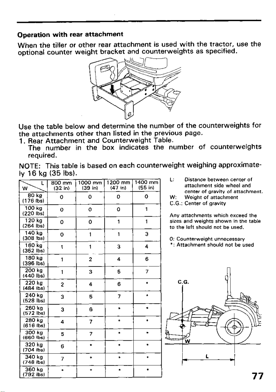
Operation with rear attachment
When the tiller or other rear attachment is used with the tractor, use the
optional counter weight bracket and counterweights as specified.
Use the table below and determine the number of the counterweights for
the attachments other than listed in the previous page.
1. Rear Attachment and Counterweight Table.
The number in the box indicates the number of counterweights
required.
NOTE: This table is based on each counterweight weighing approximate-
Iv 16 kg
(35 Ibs).
L: Distance between center of
attachment side wheel and
center of gravity of attachment.
W: Weight of attachment
C.G.: Center of gravity
Any attachments which exceed the
sizes and weights shown in the table
to the left should not be used.
0: Counterweight unnecessary
l : Attachment should not be used
C.G.
1
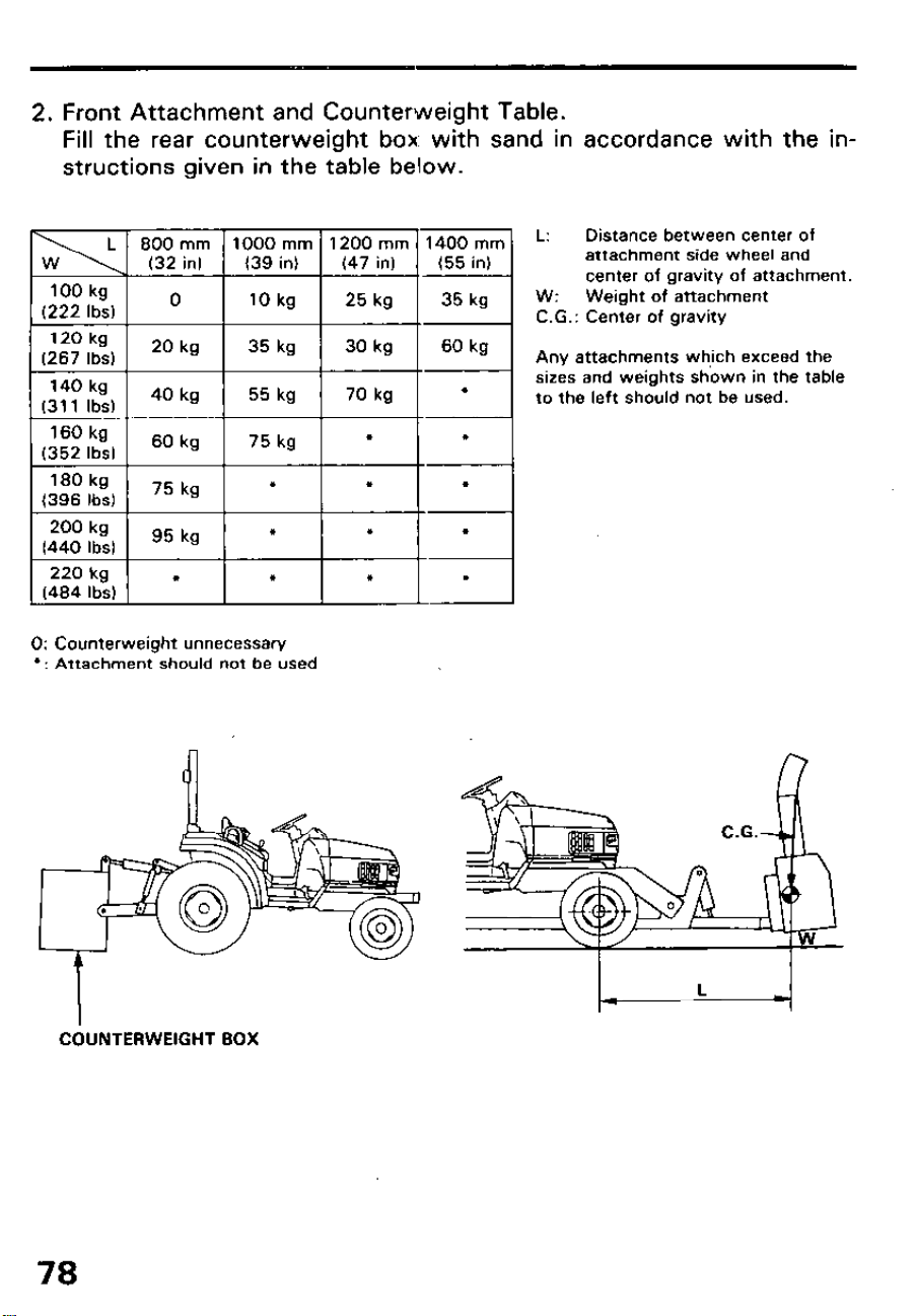
2. Front Attachment and Counterweight Table.
Fill the rear counterweight box. with sand in accordance with the in-
structions given in the table below.
L: Distance between center of
attachment side wheel and
center of gravity of attachment.
W: Weight of attachment
C.G.: Center of gravity
Any attachments wh,ich exceed the
sizes and weights shown in the table
to the left should not be used.
0: Counterweight unnecessary
l : Attachment should not be used
COUNTERWEIGHT BOX
78
11. Operation on a slope
Before starting up or down a long incline, select one of the lower gear
ranges, so that tractor speed is reduced, but engine speed is high for max-
imum control.
l Driving across the face of a slope can cause the tractor to tip over and
you can be injured. Always drive up or down a slope.
l Making turns on a slope can cause the tractor to tip over and you can be
injured. Drive straight up or straight down slopes.
l Changing gears while driving on a slope can cause loss of control. Shift
to a lower gear before approaching a slope.
l Engagement of the differential lock while driving on a slope can cause
loss of control.
l Avoid parking on a slope. If necessary, apply the parking brake and
place blocks on the downhill side of each wheel.
79
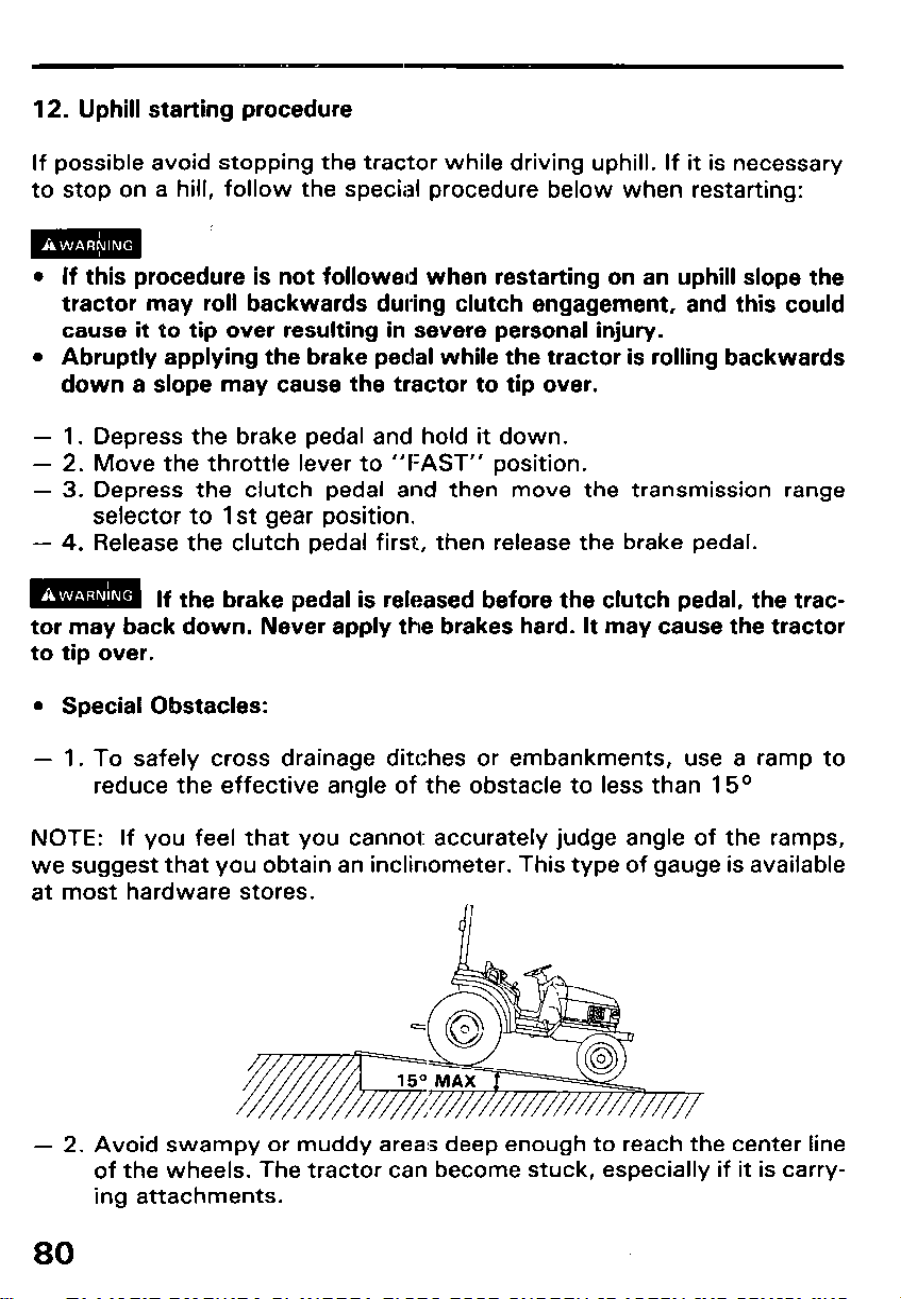
12. Uphill starting procedure
If possible avoid stopping the tractor while driving uphill. If it is necessary
to stop on a hill, follow the special procedure below when restarting:
l If this procedure is not followed when restarting on an uphill slope the
tractor may roll backwards during clutch engagement, and this could
cause it to tip over resulting in severe personal injury.
l Abruptly applying the brake pedal while the tractor is rolling backwards
down a slope may cause the tractor to tip over.
- 1. Depress the brake pedal and hold it down.
- 2. Move the throttle lever to “FAST” position.
- 3. Depress the clutch pedal and then move the transmission range
selector to 1st gear position.
- 4. Release the clutch pedal first, then release the brake pedal.
m
If the brake pedal is released before the clutch pedal, the trac-
tor may back down. Never apply the brakes hard. It may cause the tractor
to tip over.
l Special Obstacles:
- 1. To safely cross drainage ditches or embankments, use a ramp to
reduce the effective angle of the obstacle to less than 15O
NOTE: If you feel that you cannel: accurately judge angle of the ramps,
we suggest that you obtain an inclinometer. This type of gauge is available
at most hardware stores.
- 2. Avoid swampy or muddy areas deep enough to reach the center line
of the wheels. The tractor can become stuck, especially if it is carry-
ing attachments.
80
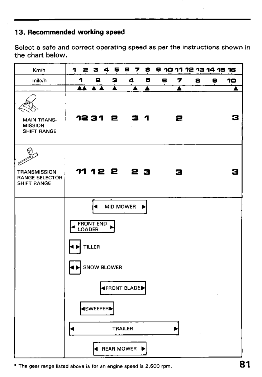
13. Recommended working speed
Select a safe and correct operating speed as per the instructions shown in
the chart below.
Kin/h 1 e 3 4 5 5 7 5
a10111513141515
mile/h 1 2 3 4 5
5 7 5 9 IO
AAAAA AA
A
A
&
MAIN TRANS- 12312 31
2 3
MISSION
SHIFT RANGE
9
rRANSMlSSlON 11122 23
3 3
3ANGE SELECTOR
SHIFT RANGE
4 TRAILER
l The gear range listed above is for an engine speed is 2,600 rpm.
81
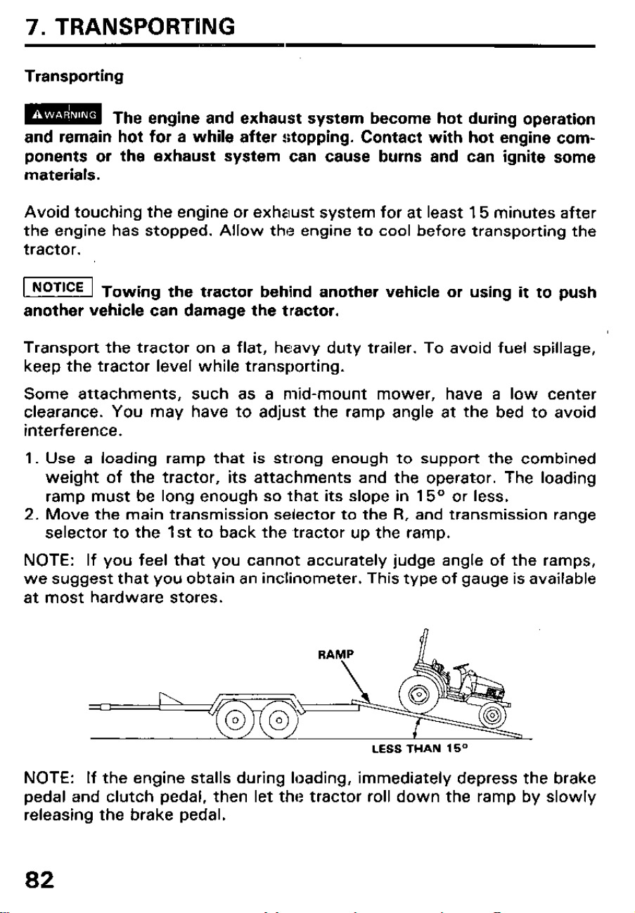
7. TRANSPORTING
Transporting
m
The engine and exhaust system become hot during operation
and remain hot for a while after stopping. Contact with hot engine com-
ponents or the exhaust system can cause burns and can ignite some
materials.
Avoid touching the engine or exhaust system for at least 15 minutes after
the engine has stopped. Allow the engine to cool before transporting the
tractor.
w Towing the tractor behind another vehicle or using it to push
another vehicle can damage the tractor.
Transport the tractor on a flat, heavy duty trailer. To avoid fuel spillage,
keep the tractor level while transporting.
Some attachments, such as a mid-mount mower, have a low center
clearance. You may have to adjust the ramp angle at the bed to avoid
interference.
1. Use a loading ramp that is strong enough to support the combined
weight of the tractor, its attachments and the operator. The loading
ramp must be long enough so that its slope in 15O or less.
2. Move the main transmission selector to the R, and transmission range
selector to the 1st to back the tractor up the ramp.
NOTE: If you feel that you cannot accurately judge angle of the ramps,
we suggest that you obtain an inclinometer. This type of gauge is available
at most hardware stores.
LESS THAN 15”
NOTE: If the engine stalls during loading, immediately depress the brake
pedal and clutch pedal, then let the tractor roll down the ramp by slowly
releasing the brake pedal.
82
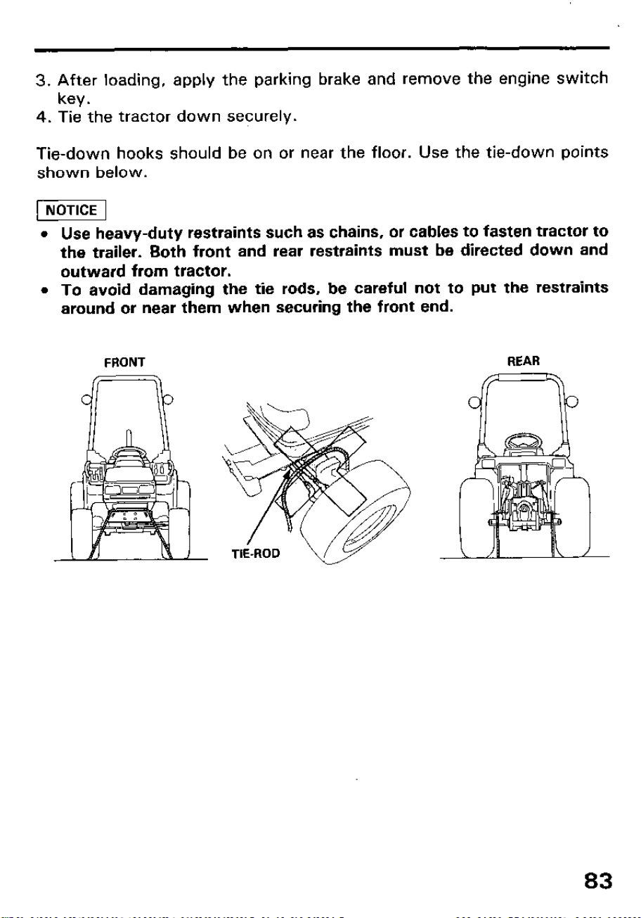
3. After loading, apply the parking brake and remove the engine switch
key.
4. Tie the tractor down securely.
Tie-down hooks should be on or near the floor. Use the tie-down points
shown below.
Use heavy-duty restraints such as chains, or cables to fasten tractor to
the trailer. Both front and rear restraints must be directed down and
outward from tractor.
To avoid damaging the tie rods, be careful not to put the restraints
around or near them when securing the front end.
FRONT
cr===b
REAR
83
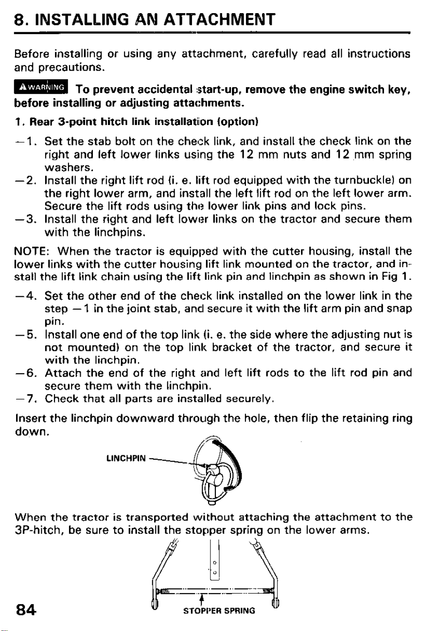
8. INSTALLING AN ATTACHMENT
Before installing or using any attachment, carefully read all instructions
and precautions.
m To prevent accidental start-up, remove the engine switch key,
before installing or adjusting attachments.
1. Rear 3-point hitch link installation (option)
- 1. Set the stab bolt on the check link, and install the check link on the
right and left lower links using the 12 mm nuts and 12 ,mm spring
washers.
-2. Install the right lift rod (i. e. lift rod equipped with the turnbuckle) on
the right lower arm, and install the left lift rod on the left lower arm.
Secure the lift rods using the lower link pins and lock pins.
-3. Install the right and left lower links on the tractor and secure them
with the linchpins.
NOTE: When the tractor is equipped with the cutter housing, install the
lower links with the cutter housing lift link mounted on the tractor, and in-
stall the lift link chain using the lift link pin and linchpin as shown in Fig 1.
-4. Set the other end of the check link installed on the lower link in the
step - 1 in the joint stab, and secure it with the lift arm pin and snap
pin.
-5. Install one end of the top link (i. e. the side where the adjusting nut is
not mounted) on the top link bracket of the tractor, and secure it
with the linchpin.
-6. Attach the end of the right and left lift rods to the lift rod pin and
secure them with the linchpin.
-7. Check that all parts are installed securely.
Insert the linchpin downward through the hole, then flip the retaining ring
down.
LINCHPIN -
When the tractor is transported without attaching the attachment to the
3P-hitch, be sure to install the stopper spring on the lower arms.
84
STOPPER SPRfNG
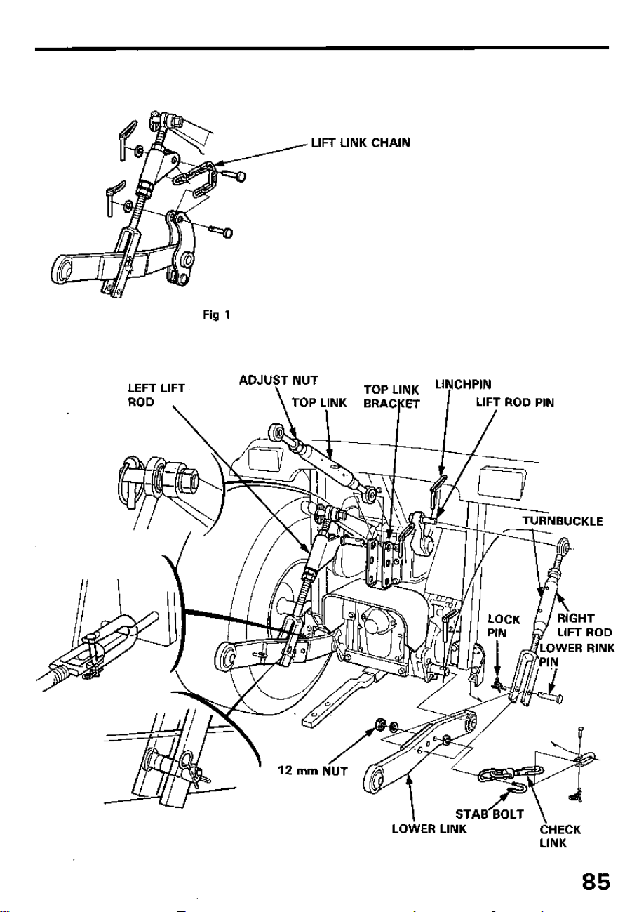
Fig 1
LIFT LINK CHAIN
TOP LIN
LEFT LIFT
ROD
\
%I II
TURNBUCKLE
/
12 mm NUT
STASGLT \
LOtiER LfNK
CHECK
LINK
85
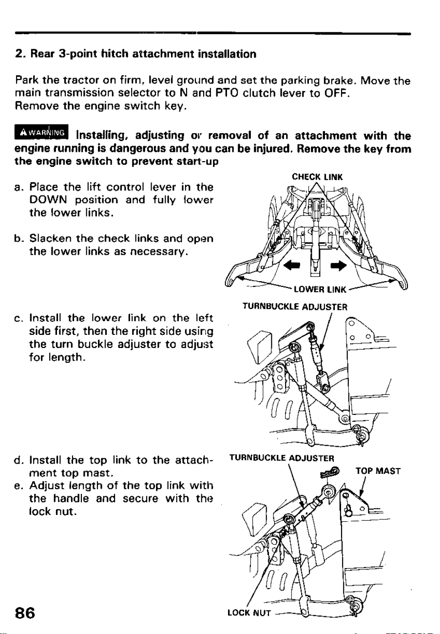
2. Rear 3-point hitch attachment installation
Park the tractor on firm, level ground and set the parking brake. Move the
main transmission selector to N and PTO clutch lever to OFF.
Remove the engine switch key.
m Installing, adjusting or removal of an attachment with the
engine running is dangerous and you can be injured. Remove the key from
the engine switch to prevent start-up
a.
Place the lift control lever in the
DOWN position and fully lower
the lower links.
b. Slacken the check links and open
the lower links as necessary.
C. Install the lower link on the left
side first, then the right side using
the turn buckle adjuster to adjust
for length.
d.
Install the top link to the attach-
TURNBUCKLE ADJUSTER
ment top mast.
Adjust length of
the handle and
lock nut.
the top link with
secure with the
\
e.
CHECK LINK
TYP MAST
86
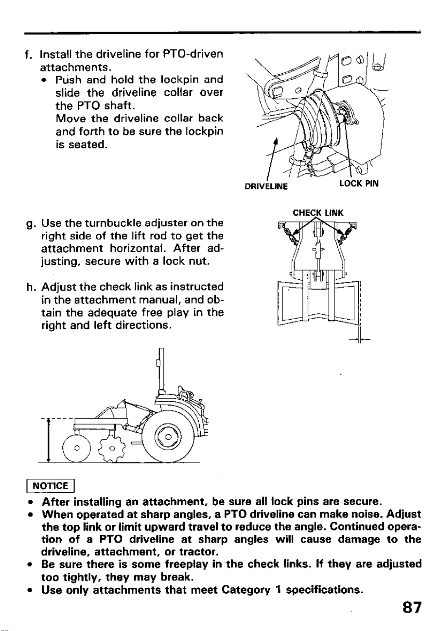
f. Install the driveline for PTO-driven
attachments.
l Push and hold the lockpin and
slide the driveline collar over
the PTO shaft.
Move the driveline collar back
and forth to be sure the lockpin
is seated.
h.
Use the turnbuckle adjuster on the
right side of the lift rod to get the
attachment horizontal. After ad-
justing, secure with a lock nut.
Adjust the check link as instructed
in the attachment manual, and ob-
tain the adequate free play in the
right and left directions.
CHECK LINK
l After installing an attachment, be sure all lock pins are secure.
l When operated at sharp angles, a PTO driveline can make noise. Adjust
the top link or limit upward travel to reduce the angle. Continued opera-
tion of a PTO driveline at sharp angles will cause damage to the
driveline, attachment, or tractor.
l Be sure there is some freeplay in the check links. If they are adjusted
too tightly, they may break.
l Use only attachments that meet Category 1 specifications.
87
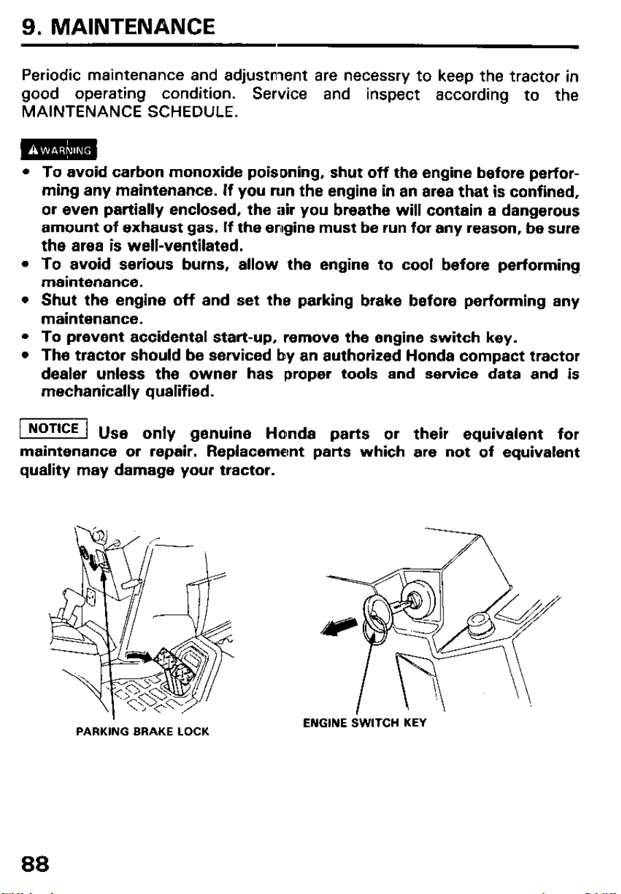
9. MAINTENANCE
Periodic maintenance and adjustment are necessry to keep the tractor in
good operating condition.
Service and inspect according to the
MAINTENANCE SCHEDULE.
l To avoid carbon monoxide poisoning, shut off the engine before perfor-
ming any maintenance. If you run the engine in an area that is confined,
or even partially enclosed, the air you breathe will contain a dangerous
amount of exhaust gas. If the engine must be run for any reason, be sure
the area is well-ventilated.
l To avoid serious burns, allow the engine to cool before performing
maintenance.
l Shut the engine off and set the parking brake before performing any
maintenance.
l To prevent accidental start-up, remove the engine switch key.
l The tractor should be serviced by an authorized Honda compact tractor
dealer unless the owner has proper tools and service data and is
mechanically qualified.
[I us
e only genuine Honda parts or their equivalent for
maintenance or repair. Replacement parts which are not of equivalent
quality may damage your tractor.
PARKING BRAKE LOCK
88
ENGINE SWITCH KEY
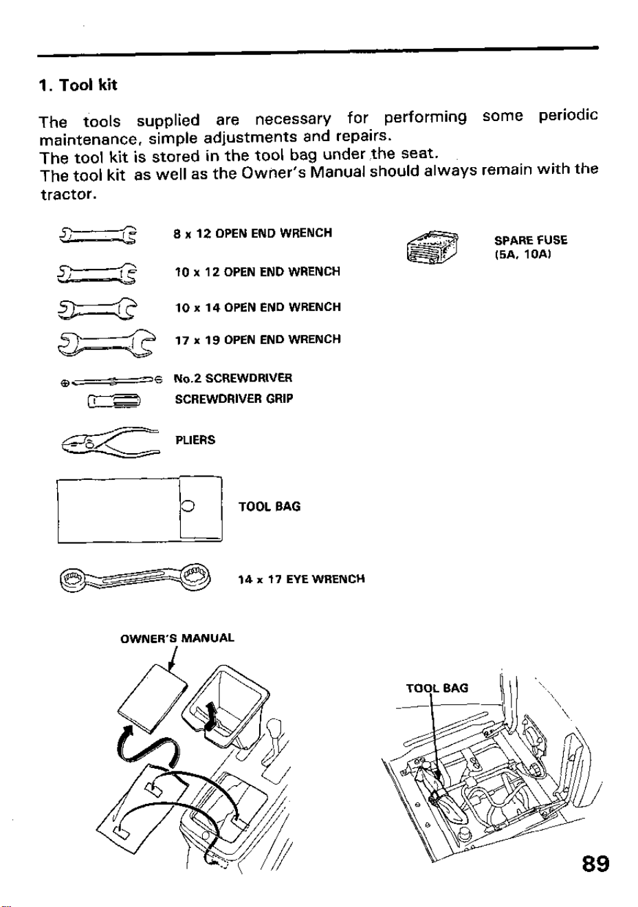
1. Tool kit
The tools supplied are
necessary for performing some periodic
maintenance, simple adjustments and repairs.
The tool kit is stored in the tool bag under ,the seat.
The tool kit as well as the Owner’s Manual should always remain with the
8 x 12 OPEN END WRENCH
SPARE FUSE
(5A, IOA)
IO x 12 OPEN END WRENCH
IO x 14 OPEN END WRENCH
17 x 19 OPEN END WRENCH
No.2 SCREWDRIVER
SCREWDRIVER GRIP
PLIERS
rfl TOOL BAG
14 x 17 EYE WRENCH
OWNER’S MANUAL
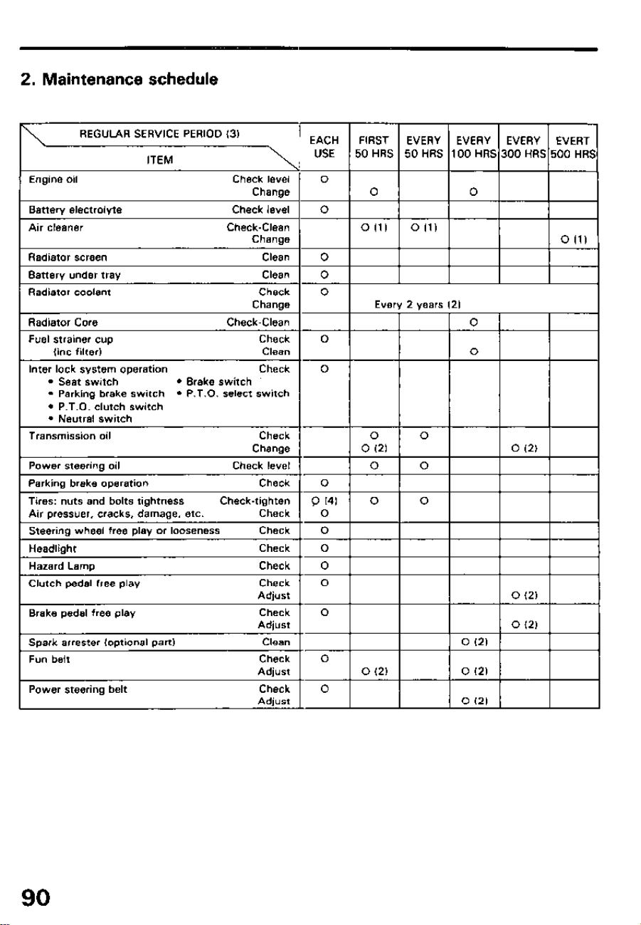
2. Maintenance schedule
REGULAR SERVICE PERIOD (31
ITEM
’ EACH FIRST
USE 50 HRS
Engine oil
Battery electrolyte
Air cleaner
1 0 (1)
Radiator screen Clean I 0 I
Banery under tray
Radiator coolant
Inter lock system operation
l Seat switch
l Brake switch
l P.T.O. select switch
90
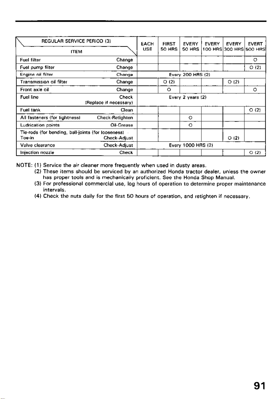
REGULAR SERVICE PERIOD (3)
EACH FIRST EVERY EVERY EVERY EVERT
ITEM
USE 50 HRS 50 HRS 100 HRS 300 HRS 500 HRS
Fuel filter Chanoe 0
1 Fuel burnt filter Change 1
I I I I I 0 12) I
Engine oil filter
Transmission oil filter
Front axle oil
Change
Change
Change
Every 200 HRS (2)
0 (2)
1 0 (2)
I 0 I I 0
Fuel line Check
(Replace if necessary)
Fuel tank Clean
All fasteners (for tightness) Check-Retighten
Ludrication points
Oil-Grease
Tie-rods (for bending, ball-joints (for looseness)
Toe-in
Check-Adjust
Valve clearance Check-Adiust
Every 2 Years (2)
0 (2)
0
0
0 (21
Everv 1000 HRS 12)
Injection nozzle
Check 1
1 0 12)
NOTE: (1) Service the air cleaner more frequently when used in dusty areas.
(2) These items should be serviced by an authorized Honda tractor dealer, unless the owner
has proper tools and is mechanically proficient. See the Honda Shop Manual.
(3) For professional commercial use, log hours of operation to determine proper maintenance
intervals.
(4) Check the nuts daily for the first 50 hours of operation, and retighten if necessary.
91
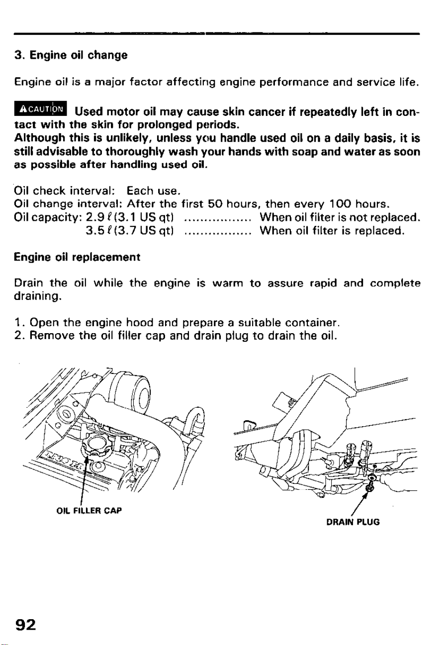
3. Engine oil change
Engine oil is a major factor affecting engine performance and service life.
m
Used motor oil mav cause skin cancer if reoeatedlv left in con-
tact with the skin for prolonged periods.
Although this is unlikely, unless you handle used oil on a daily basis, it is
still advisable to thoroughly wash your hands with soap and water as soon
as possible after handling used oil.
Oil check interval: Each use.
Oil change interval: After the first 50 hours, then every 100 hours.
Oil capacity: 2.9 P (3.1 US qt)
. . . . . . . . . . . . . . . . . When oil filter is not replaced.
3.5 P(3.7 US qt) . . . . . . . . . . . . . . . . . When oil filter is replaced.
Engine oil replacement
Drain the oil while the engine is warm to assure rapid and complete
draining.
1. Open the engine hood and prepare a suitable container.
2. Remove the oil filler cap and drain plug to drain the oil.
OIL FiLLER CAP
/
DRAIN PLUG
92
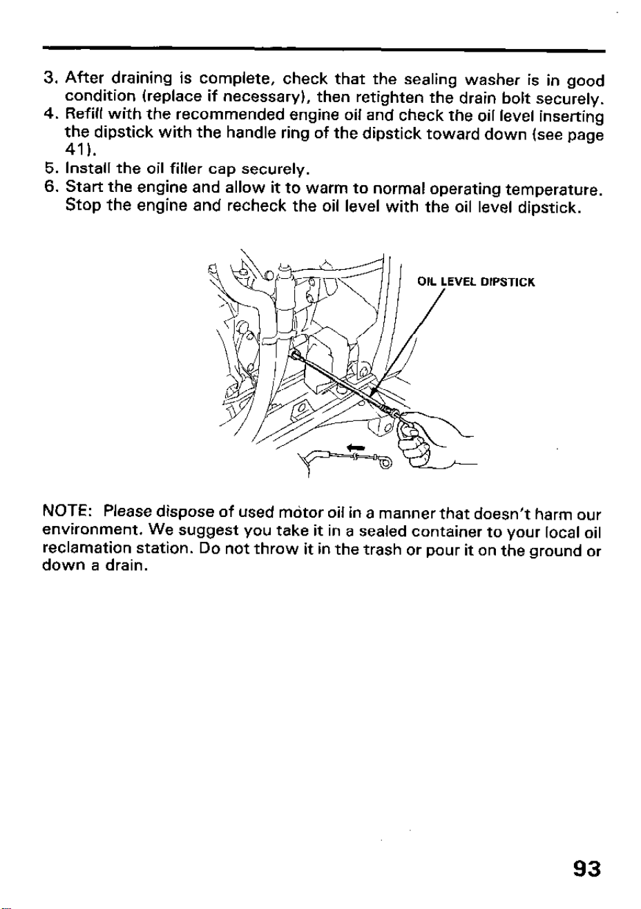
3.
4.
5.
6.
After draining is complete, check that the sealing washer is in good
condition (replace if necessary), then retighten the drain bolt securely.
Refill with the recommended engine oil and check the oil level inserting
the dipstick with the handle ring of the dipstick toward down (see page
41).
Install the oil filler cap securely.
Start the engine and allow it to warm to normal operating temperature.
Stop the engine and recheck the oil level with the oil level dipstick.
DIPSTICK
NOTE:
Please dispose of used mdtor oil in a manner that doesn’t harm our
environment. We suggest you take it in a sealed container to your local oil
reclamation station. Do not throw it in the trash or pour it on the ground or
down a drain.
93
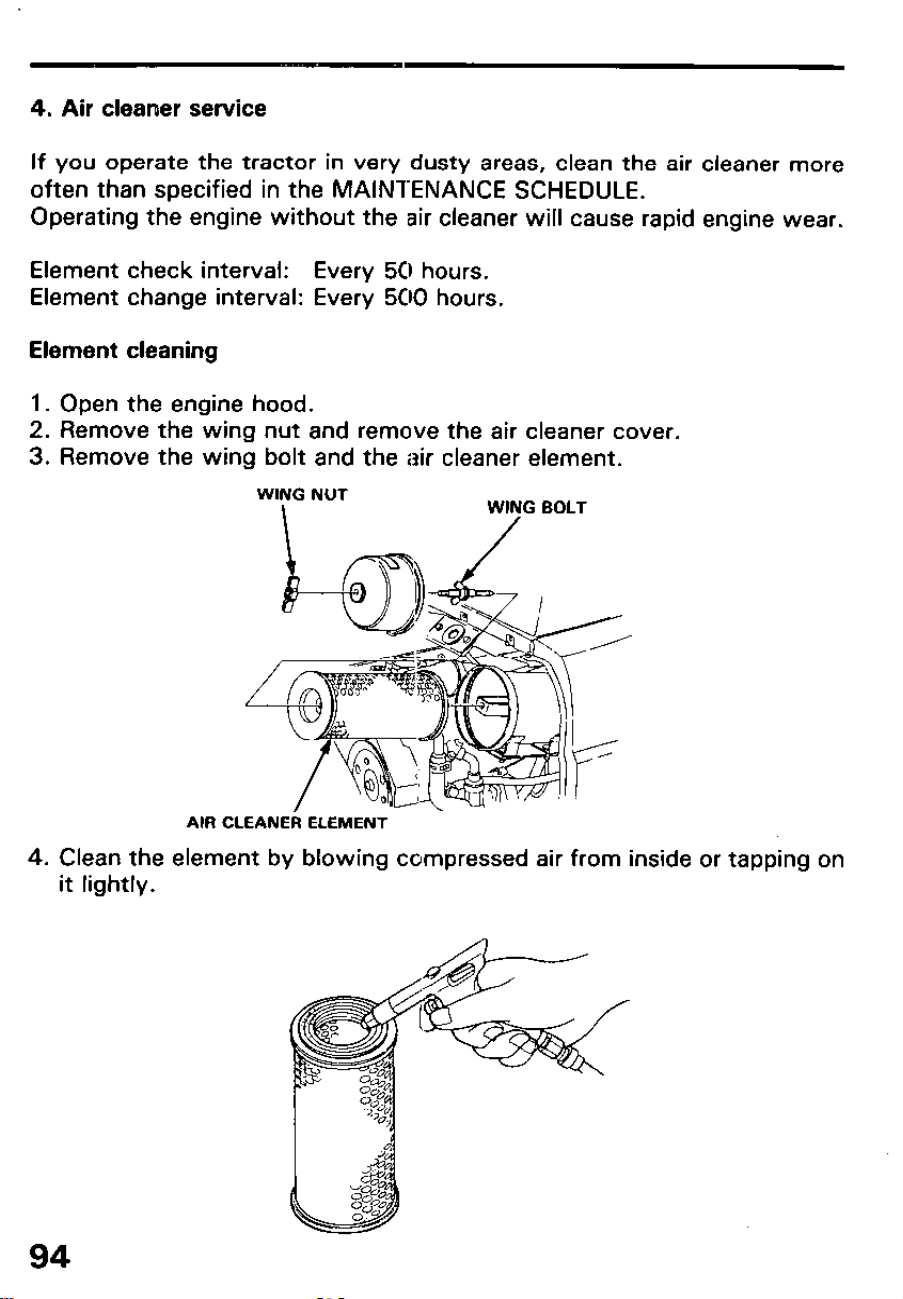
4. Air cleaner service
If you operate the tractor in very dusty areas, clean the air cleaner more
often than specified in the MAINTENANCE SCHEDULE.
Operating the engine without the air cleaner will cause rapid engine wear.
Element check interval: Every 50 hours.
Element change interval: Every 500 hours.
Element cleaning
1. Open the engine hood.
2. Remove the wing nut and remove the air cleaner cover.
3. Remove the wing bolt and the air cleaner element.
WING NUT
I
WING BOLT
/
AIR CLEANER ELEMENT
4. Clean the element by blowing compressed air from inside or tapping on
it lightly.
94
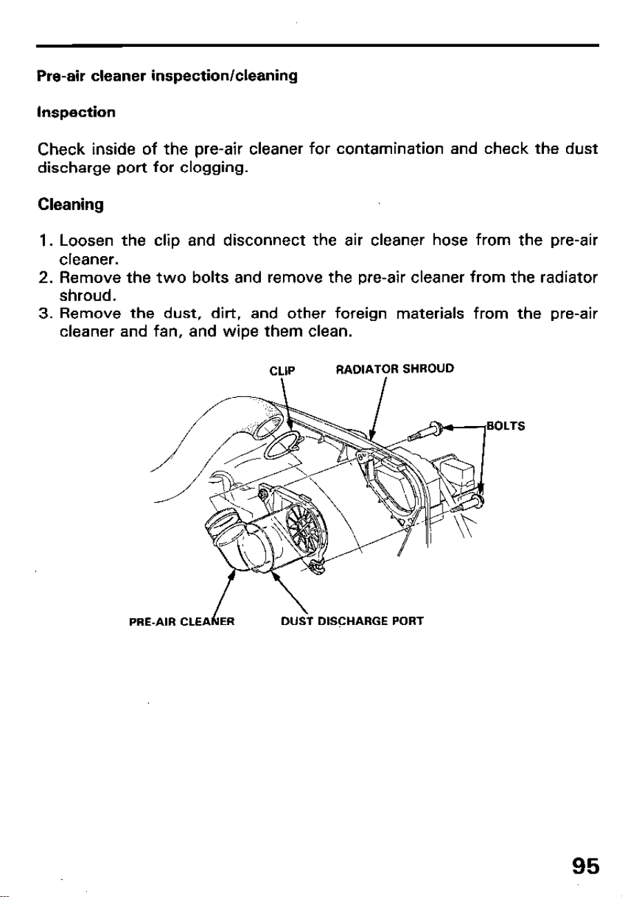
Pre-air cleaner inspection/cleaning
Inspection
Check inside of the pre-air cleaner for contamination and check the dust
discharge port for clogging.
Cleaning
1. Loosen the clip and disconnect the air cleaner hose from the pre-air
cleaner.
2. Remove the two bolts and remove the pre-air cleaner from the radiator
shroud.
3. Remove the dust, dirt, and other foreign materials from the pre-air
cleaner and fan, and wipe them clean.
CLIP
RADIATOR SHROUD
BOLTS
PRE-AIR CLEAhER
DUSi DISCHARGE PORT
95
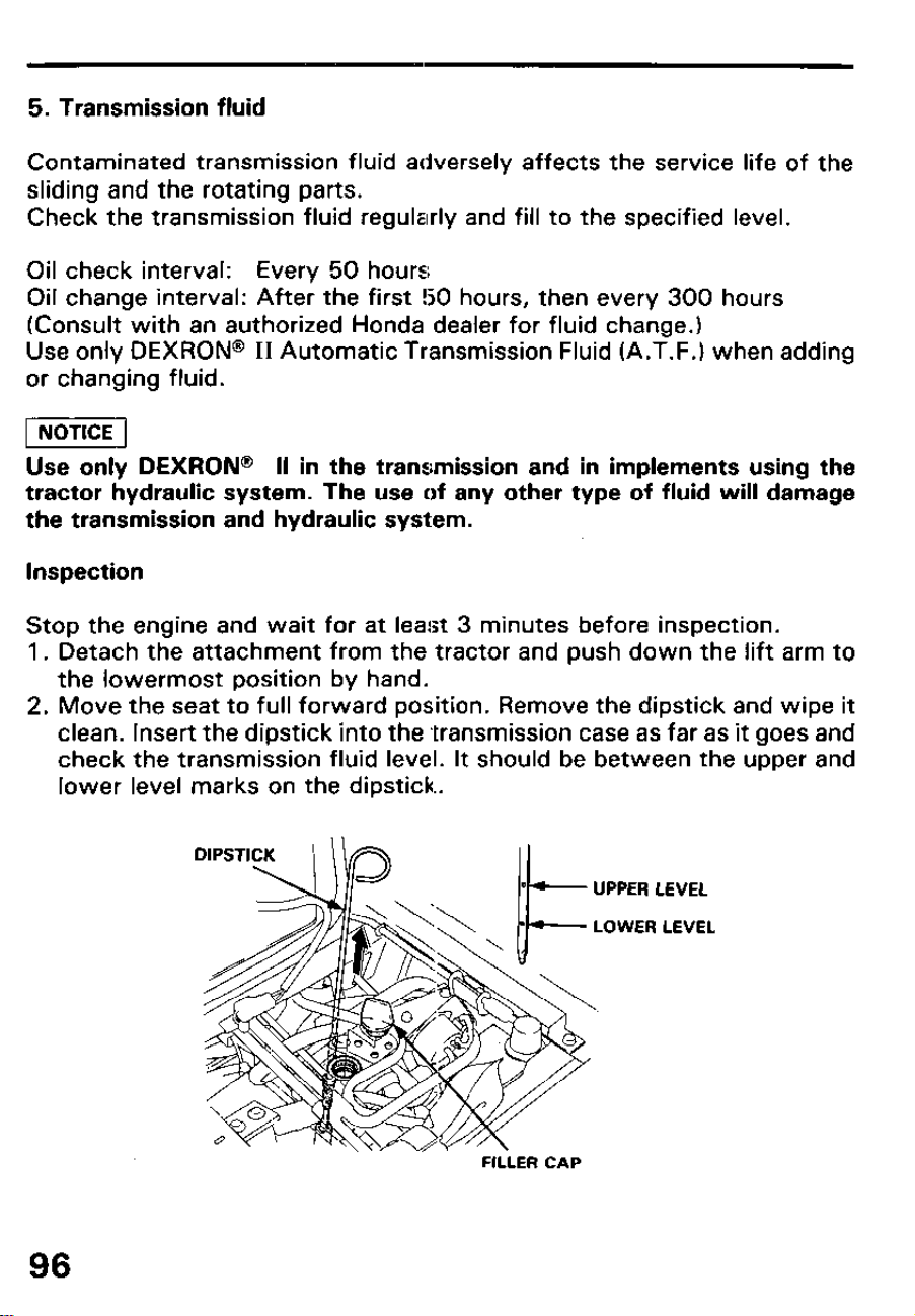
5. Transmission fluid
Contaminated transmission fluid adversely affects the service life of the
sliding and the rotating parts.
Check the transmission fluid regularly and fill to the specified level.
Oil check interval: Every 50 hours
Oil change interval: After the first !50 hours, then every 300 hours
(Consult with an authorized Honda dealer for fluid change.)
Use only DEXRON@ II Automatic Transmission Fluid (A.T.F.) when adding
or changing fluid.
piiiq
Use only DEXRON @ II in the transmission and in implements using the
tractor hydraulic system. The use of any other type of fluid will damage
the transmission and hydraulic system.
Inspection
Stop the engine and wait for at least 3 minutes before inspection.
1. Detach the attachment from the tractor and push down the lift arm to
the lowermost position by hand.
2. Move the seat to full forward position. Remove the dipstick and wipe it
clean. Insert the dipstick into the transmission case as far as it goes and
check the transmission fluid level. It should be between the upper and
lower level marks on the dipstick.
UPPER LEVEL
LOWER LEVEL
FILLER CAP
96
3. If the oil level is near or below the lower level mark, remove the filler cap
and add fresh transmission fluid to the upper level mark on the dipstick.
w If the transmission fluid level dropped excessively in a short
period, the hydraulic system might be faulty. Consult with an authorized
Honda compact tractor dealer.
97
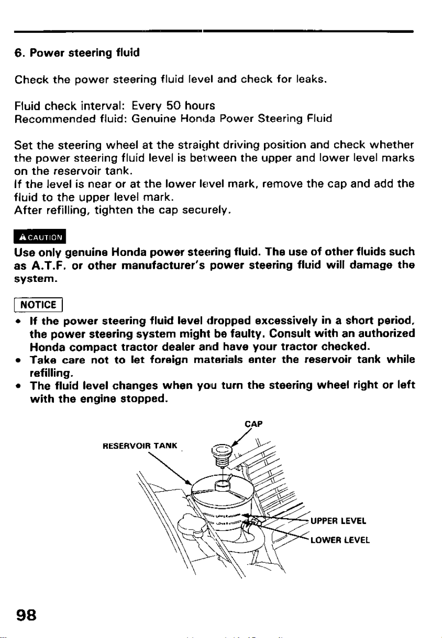
6. Power steering fluid
Check the power steering fluid level and check for leaks.
Fluid check interval: Every 50 hours
Recommended fluid: Genuine Honda Power Steering Fluid
Set the steering wheel at the straight driving position and check whether
the power steering fluid level is between the upper and lower level marks
on the reservoir tank.
If the level is near or at the lower level mark, remove the cap and add the
fluid to the upper level mark.
After refilling, tighten the cap securely.
Use only genuine Honda power steering fluid. The use of other fluids such
as A.T.F. or other manufacturer’s power steering fluid will damage the
system.
l If the power steering fluid level dropped excessively in a short period,
the power steering system might be faulty. Consult with an authorized
Honda compact tractor dealer and have your tractor checked.
l Take care not to let foreign materials enter the reservoir tank while
refilling.
l The fluid level changes when yolu turn the steering wheel right or left
with the engine stopped.
CAP
UPPER LEVEL
LOWER LEVEL
98
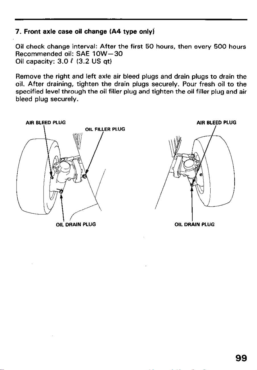
7. Front axle case oil change (A4 type only]
Oil check change interval: After the first 50 hours, then every 500 hours
Recommended oil: SAE 1 OW-30
Oil capacity: 3.0 e (3.2 US qt)
Remove the right and left axle air bleed plugs and drain plugs to drain the
oil. After draining, tighten the drain plugs securely. Pour fresh oil to the
specified level through the oil filler plug and tighten the oil filler plug and air
bleed plug securely.
AIR BLEED PLUG
AIR BLEED PLUG
PLUG
Oli DRAIN PLUG
OIL DRilN PLUG
99
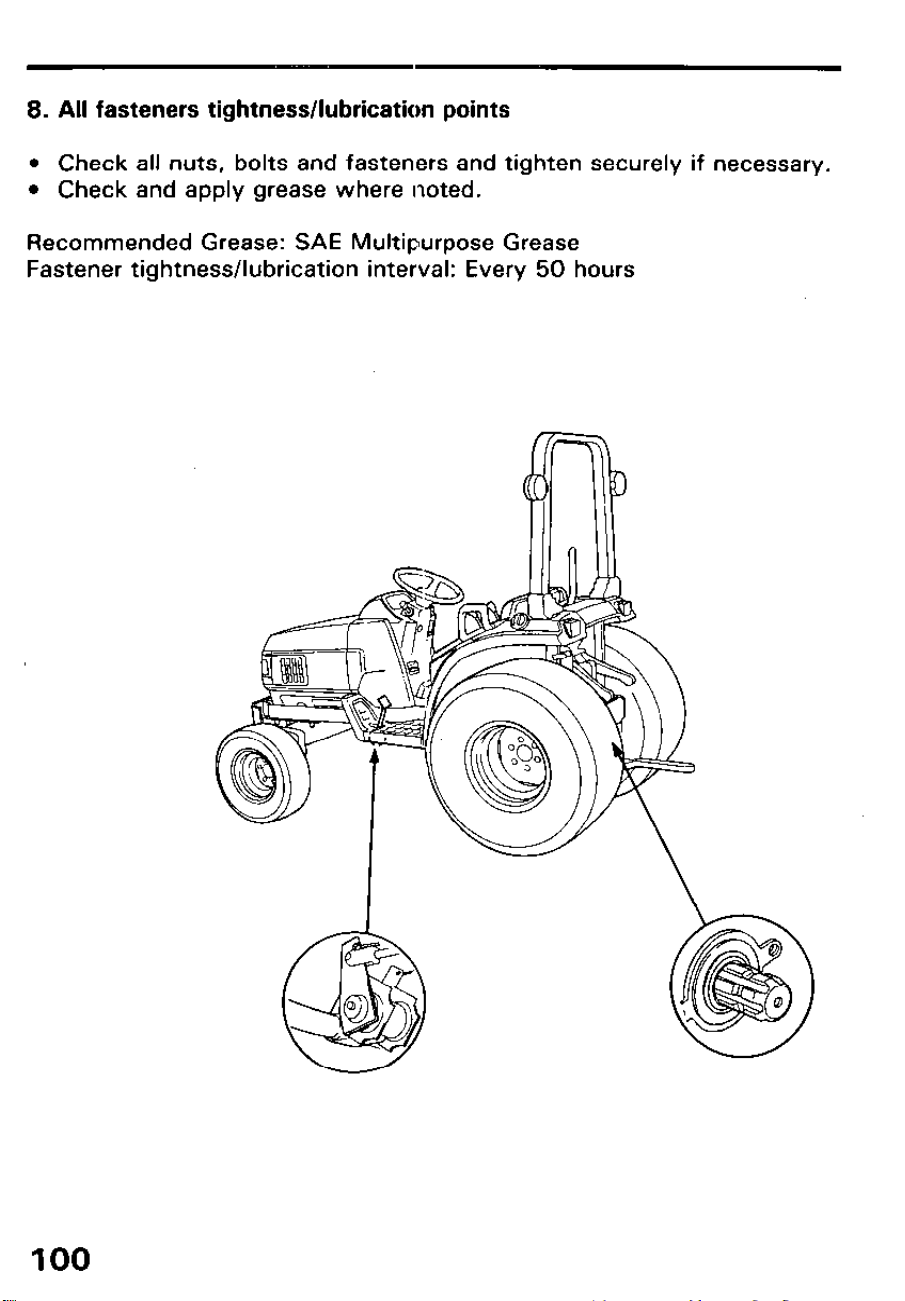
8. All fasteners tightness/lubrication points
l Check all nuts, bolts and fasteners and tighten securely if necessary.
l Check and apply grease where noted.
Recommended Grease: SAE Multipurpose Grease
Fastener tightness/lubrication interval: Every 50 hours
100
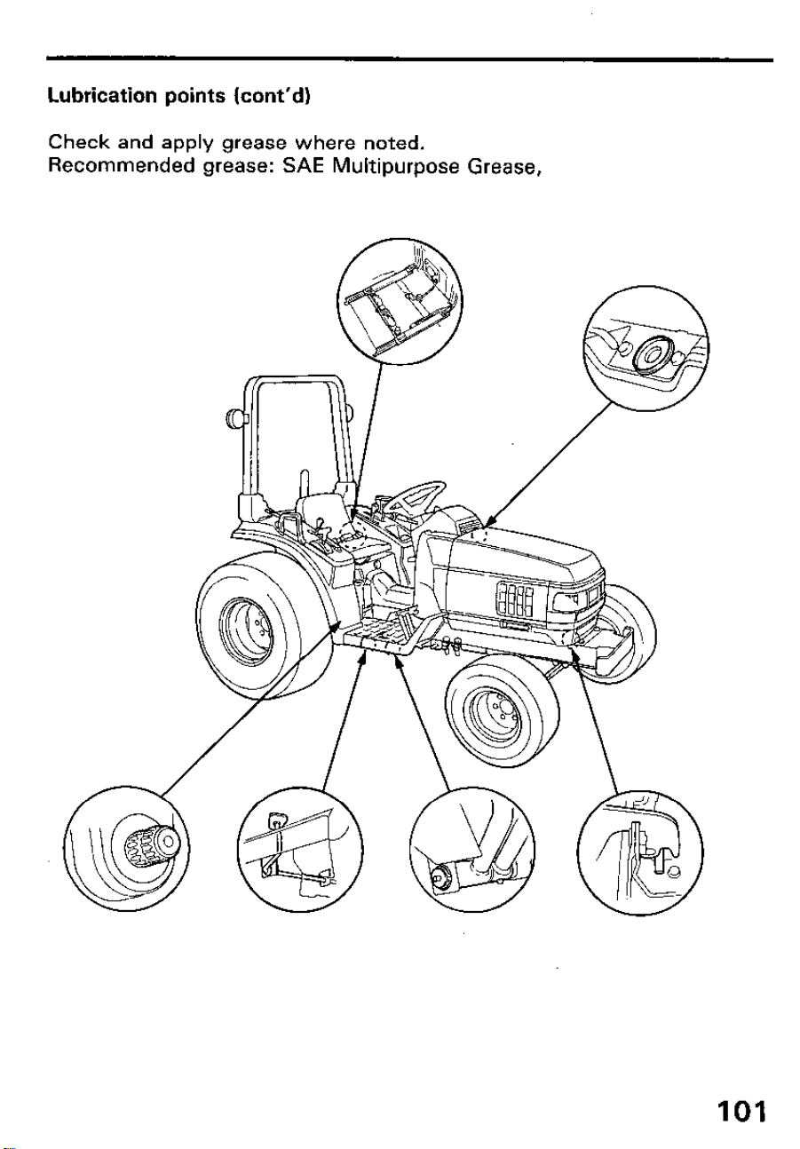
Lubrication points (cont’d)
Check and apply grease where noted.
Recommended grease: SAE Multipurpose Grease,
101
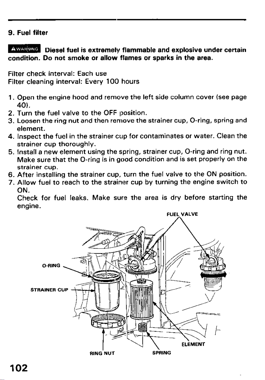
9. Fuel filter
m
Diesel fuel is extremely flammable and explosive under certain
condition. Do not smoke or allow flames or sparks in the area.
Filter check interval: Each use
Filter cleaning interval: Every 100 hours
1. Open the engine hood and remove the left side column cover (see page
40).
2. Turn the fuel valve to the OFF position.
3. Loosen the ring nut and then remove the strainer cup, O-ring, spring and
element.
4. Inspect the fuel in the strainer cup for contaminates or water. Clean the
strainer cup thoroughly.
5. Install a new element using the spring, strainer cup, O-ring and ring nut.
Make sure that the O-ring is in good condition and is set properly on the
strainer cup.
6. After installing the strainer cup, turn the fuel valve to the ON position.
7. Allow fuel to reach to the strainer cup by turning the engine switch to
ON.
Check for fuel leaks. Make sure the area is dry before starting the
engine.
FUEL VALVE
O-RING
STRAINER CUP
RING NUT
SPRING
102
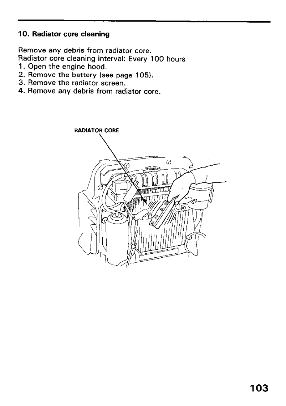
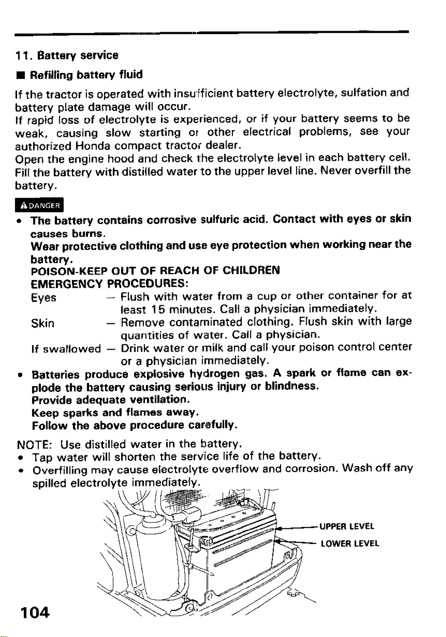
11. Battery service
n Refilling battery fluid
If the tractor is operated with insufficient battery electrolyte, sulfation and
battery plate damage will occur.
If rapid loss of electrolyte is experienced, or if your battery seems to be
weak, causing slow starting or other electrical problems, see your
authorized Honda compact tractor dealer.
Open the engine hood and check the electrolyte level in each battery cell.
Fill the battery with distilled water to the upper level line. Never overfill the
battery.
l The battery contains corrosive sulfuric acid. Contact with eyes or skin
causes burns.
Wear protective clothing and use eye protection when working near the
battery.
POISON-KEEP OUT OF REACH OF CHILDREN
EMERGENCY PROCEDURES:
Eyes -
Flush with water from a cup or other container for at
least 15 minutes. Call a physician immediately.
Skin - Remove contaminated clothing. Flush skin with large
quantities of water. Call a physician.
If swallowed - Drink water or milk and call your poison control center
or a physician immediately.
l Batteries produce explosive hydrogen gas. A spark or flame can ex-
plode the battery causing serious injury or blindness.
Provide adequate ventilation.
Keep sparks and flames away.
Follow the above procedure carefully.
NOTE: Use distilled water in the battery.
l Tap water will shorten the service life of the battery.
l Overfilling may cause electrolyte overflow and corrosion. Wash off any
spilled electrolyte immediately.
UPPER LEVEL
LOWER LEVEL
104
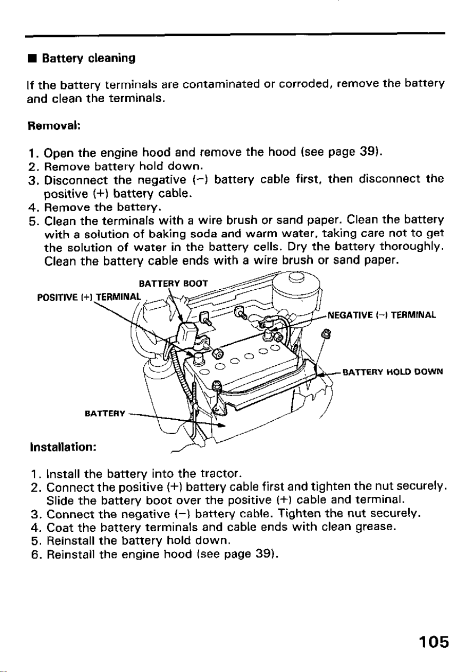
n Battery cleaning
If the battery terminals are contaminated or corroded, remove the battery
and clean the terminals.
Removal:
1. Open the engine hood and remove the hood (see page 39).
2. Remove battery hold down.
3. Disconnect the negative (-1 battery cable first, then disconnect the
positive (+I battery cable.
4. Remove the battery.
5. Clean the terminals with a wire brush or sand paper. Clean the battery
with a solution of baking soda and warm water, taking care not to get
the solution of water in the battery cells. Dry the battery thoroughly.
Clean the battery cable ends with a wire brush or sand paper.
EGATIVE I-1 TERMINAL
BATTERY HOLD DOWN
Installation:
1. Install the battery into the tractor.
2. Connect the positive (+) battery cable first and tighten the nut securely.
Slide the battery boot over the positive (+) cable and terminal.
3. Connect the negative (-1 battery cable. Tighten the nut securely.
4. Coat the battery terminals and cable ends with clean grease.
5. Reinstall the battery hold down.
6. Reinstall the engine hood (see page 39).
105
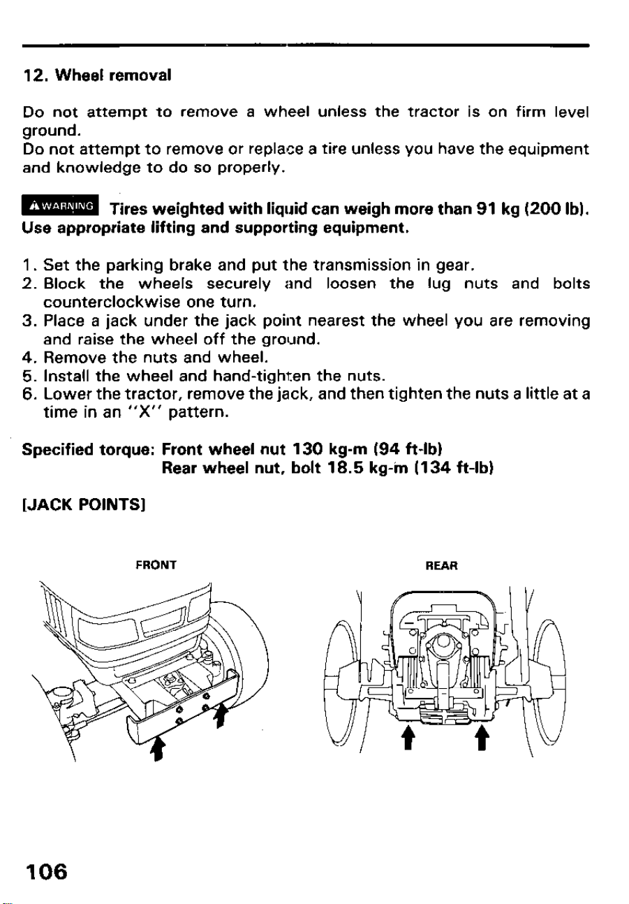
12. Wheel removal
Do not attempt to remove a wheel unless the tractor is on firm level
ground.
Do not attempt to remove or replace a tire unless you have the equipment
and knowledge to do so properly.
m Tires weighted with liquid can weigh more than 91 kg (200 lb).
Use appropriate lifting and supporting equipment.
1. Set the parking brake and put the transmission in gear.
2. Block the wheels securely and loosen the lug nuts and bolts
counterclockwise one turn.
3. Place a jack under the jack point nearest the wheel you are removing
and raise the wheel off the ground.
4. Remove the nuts and wheel.
5. Install the wheel and hand-tighten the nuts.
6. Lower the tractor, remove the jack, and then tighten the nuts a little at a
time in an “X” pattern.
Specified torque: Front wheel nut 130 kg-m (94 ft-lb)
Rear wheel nut, bolt 18.5 kg-in (134 h-lb)
[JACK POINTS]
FRONT
REAR
106
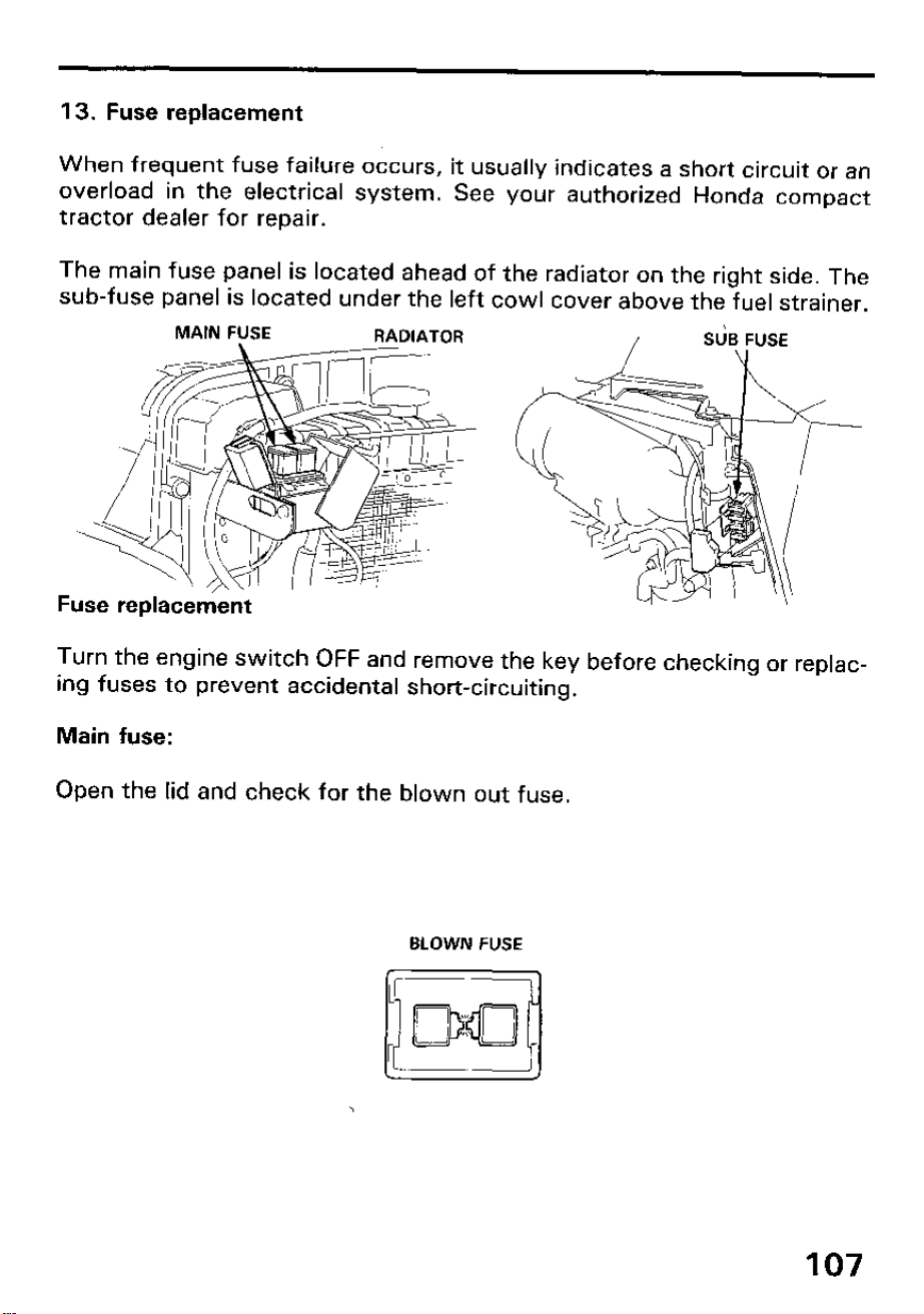
13. Fuse replacement
When frequent fuse failure occurs, it usually indicates a short circuit or an
overload in the electrical system. See your authorized Honda compact
tractor dealer for repair.
The main fuse panel is located ahead of the radiator on the right side. The
sub-fuse panel is located under the left cowl cover above the fuel strainer.
Fuse replacement
Turn the engine switch OFF and remove the key before checking or replac-
ing fuses to prevent accidental short-circuiting.
Main fuse:
Open the lid and check for the blown out fuse.
BLOWN FUSE
107
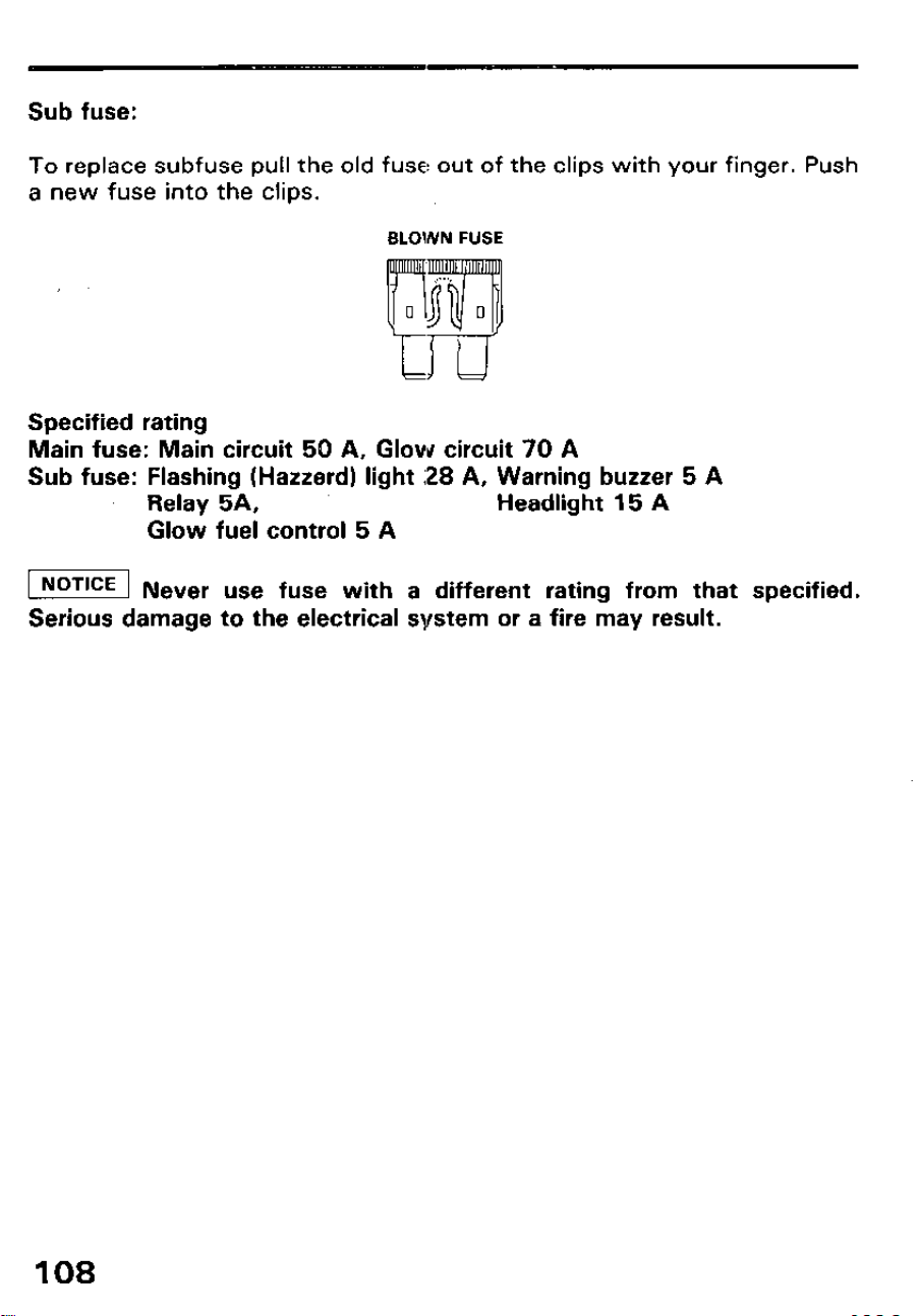
Sub fuse:
To replace subfuse pull the old fuse out of the clips with your finger. Push
a new fuse into the clips.
BLOWN FUSE
Specified rating
Main fuse: Main circuit 50 A, Glow circuit 70 A
Sub fuse: Flashing (Hazterd) light ;28 A, Warning buzzer 5 A
Relay 5A,
Headlight 15 A
Glow fuel control 5 A
w Never use fuse with a different rating from that specified.
Serious damage to the electrical system or a fire may result.
108
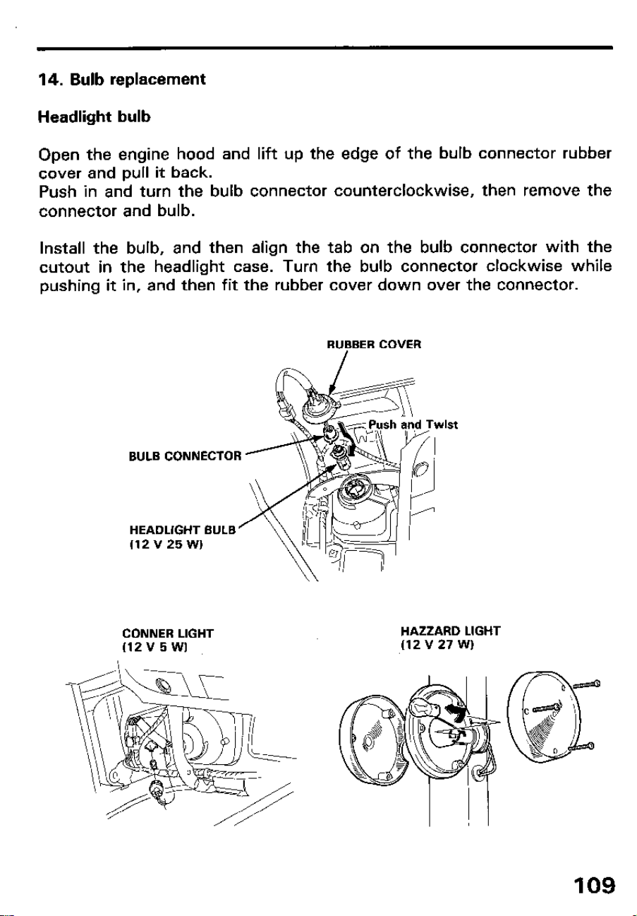
14. Bulb replacement
Headlight bulb
Open the engine hood and lift up the edge of the bulb connector rubber
cover and pull it back.
Push in and turn the bulb connector counterclockwise, then remove the
connector and bulb.
Install the bulb, and then align the tab on the bulb connector with the
cutout in the headlight case. Turn the bulb connector clockwise while
pushing it in, and then fit the rubber cover down over the connector.
RUBBER COVER
BULB CONNECTOR
HEADLIGHT BULB’
(12 v 25 W)
CONNER LIGHT
(12 v 5 WI
HAZZARD LIGHT
(12 V 27 WI
10. LONG TERfUi STORAGE
Storage
The engine becomes very hot during operation and remains hot for a while
after stopping. Allow the engine to cool before storing.
m
Contact with a hot engine or exhaust system can cause serious
burns or fires. Let the engine cool lbefore storing.
m
When storing, remove the key from the key switch to avoid
unauthorized persons from operating’ the tractor and getting injured. To
avoid the danger of exhaust fume poisoning, do not operate the engine in a
closed building without proper ventilation.
When the tractor will not be operated for two or three months or longer,
clean the tractor and perform the following treatment before storage.
1. Repair any, parts as needed.
2. Check nuts and bolts, as necessary.
3. Apply gease or engine oil to the parts most likely to rust.
4. Inflate the tires to little above the standard pressure levels.
5. Change the engine oil and run the engine for five minutes so that the oil
circurales thoroughout the entire lubrication system.
6. Stop the eingine and remove the key.
110
7. Drain the radiator. Flush and refill with new coolant.
8. Lower the implement to the ground.
9. Remove the battery from the tractor, recharge it, adjust the electrolyte
to the proper level, and store in a cool, dry place.
10. The battery runs down over time even while in storage. Recharge it
once a month in hot seasons and once every two months in cold
seasons.
11. Store the tractor where dry and sheltered from rain.
Removal from storage
1. Check the battery electrolyte level (see p. 1041. Fully recharge the bat-
tery, and install it in the tractor.
2. Check the engine oil level (see p. 41)
3. Check the coolant level (see p. 42)
4. Check the tire pressure (see p. 39)
111
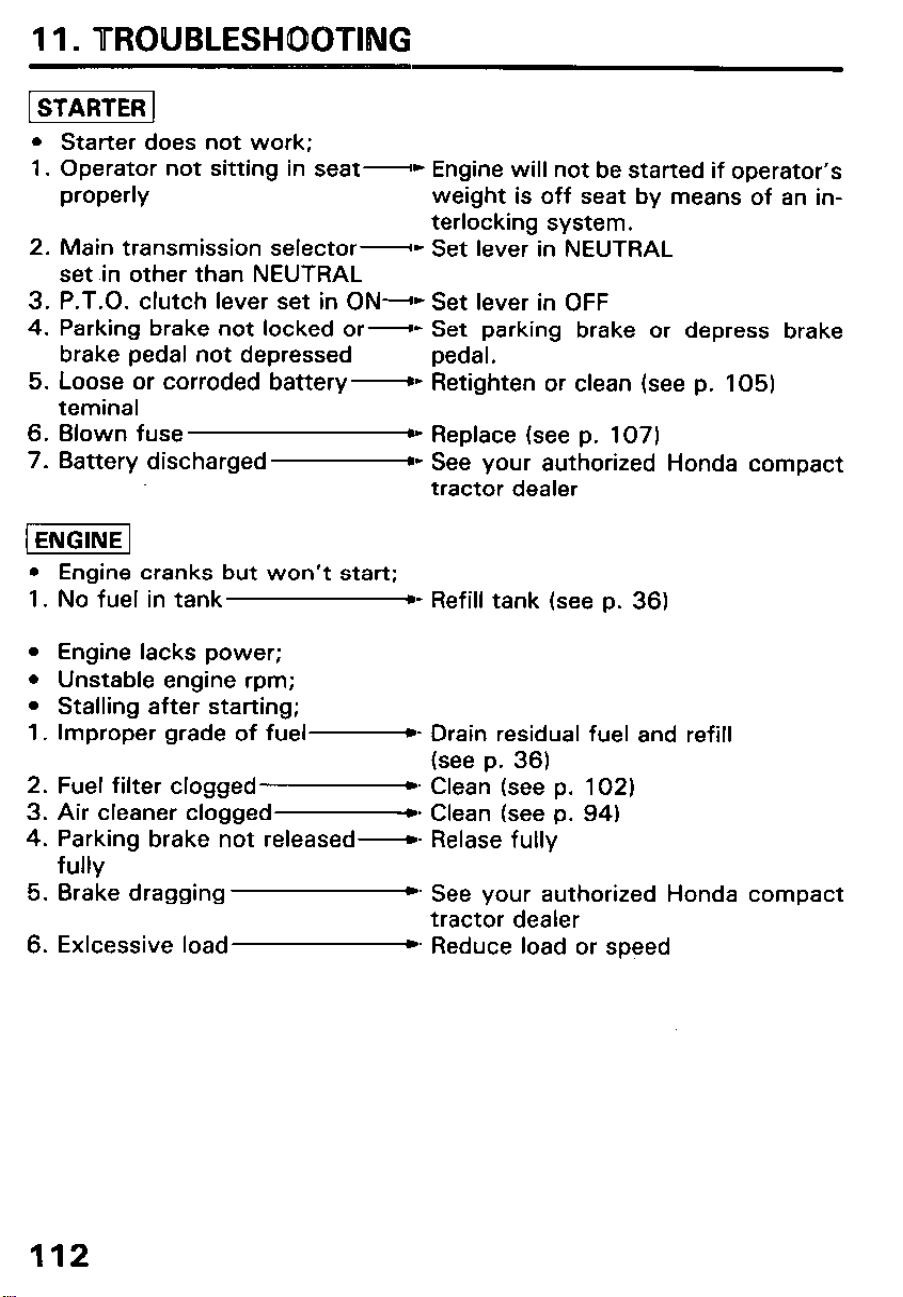
11. UROUBLESHOOTIBUG
[ STARTER 1
l Starter does not work;
1. Operator not sitting in
seat-
c Engine will not be started if operator’s
properly weight is off seat by means of an in-
terlocking system.
2. Main transmission selector
-c Set lever in NEUTRAL
set in other than NEUTRAL
3. P.T.O. clutch lever set in ON--o Set lever in OFF
4. Parking brake not locked or-
D Set parking brake or depress brake
brake pedal not depressed pedal.
5. Loose or corroded battery--
Retighten or clean (see p. 105)
teminal
6. Blown fuse
B- Replace (see p. 107)
7. Battery discharged PC
See your authorized Honda compact
tractor dealer
l Engine cranks but won’t start;
1. No fuel in tank l - Refill tank (see p. 36)
l Engine lacks power;
l Unstable engine rpm;
l Stalling after starting;
1. Improper grade of fuel- Drain residual fuel and refill
(see p. 36)
2. Fuel filter clogged m- Clean (see p. 102)
3. Air cleaner clogged*. Clean (see p. 94)
4. Parking brake not released--
Relase fully
fully
5. Brake dragging
) See your authorized Honda compact
tractor dealer
6. Exlcessive load b Reduce load or speed
112
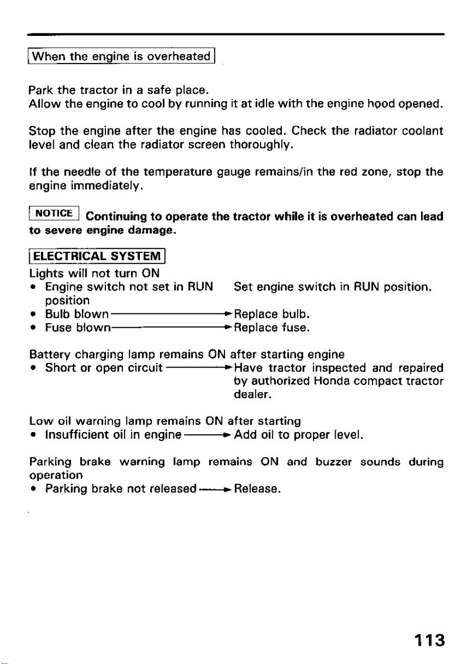
1 When the enaine is overheated 1
Park the tractor in a safe place.
Allow the engine to cool by running it at idle with the engine hood opened.
Stop the engine after the engine has cooled. Check the radiator coolant
level and clean the radiator screen thoroughly.
If the needle of the temperature gauge remains/in the red zone, stop the
engine immediately.
( Continuing to operate the tractor while it is overheated can lead
to severe engine damage.
rELECTRlCAL SYSTEM 1
Lights will not turn ON
l Engine switch not set in RUN
Set engine switch in RUN position.
position
l Bulb blown
*Replace bulb.
l Fuse blown
) Replace fuse.
Battery charging lamp remains ON after starting engine
l Short or open circuit -Have tractor inspected and repaired
by authorized Honda compact tractor
dealer.
Low oil warning lamp remains ON after starting
l Insufficient oil in engine- Add oil to proper level.
Parking brake warning lamp remains ON and buzzer sounds during
operation
l Parking brake not released- Release.
113
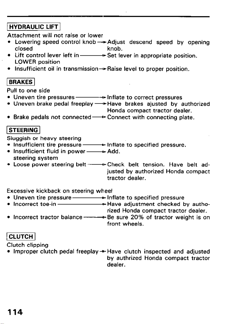
1 HYDRAULIC LIFT 1
Attachment will not raise or lower
l Lowering speed control knob --,Adjust descend speed by opening
closed
knob.
l Lift control lever left in
-eSet lever in appropriate position.
LCWER position
l Insufficient oil in transmission-+Raise level to proper position.
-1
Pull to one side
l Uneven tire pressures -w Inflate to correct pressures
l Uneven brake pedal freeplay
-Have brakes ajusted by authorized
Honda compact tractor dealer.
l Brake pedals not connected- Connect with connecting plate.
l-cEiiq
Sluggish or heavy steering
l Insufficient tire pressure -- Inflate to specified pressure.
l Insufficient fluid in power -D Add.
steering system
l Loose power steering belt BbCheck belt tension. Have belt ad-
justed by authorized Honda compact
tractor dealer.
Excessive kickback on steering wheel
l Uneven tire pressure--
Inflate to specified pressure
l Incorrect toe-in
~-Have adjustment checked by autho-
rized Honda compact tractor dealer.
l Incorrect tractor balance --
Be sure 20% of tractor weight is on
front wheels.
l-ziimq
Clutch clipping
l Improper clutch pedal freeplay
+-Have clutch inspected and adjusted
by authrized Honda compact tractor
dealer.
114
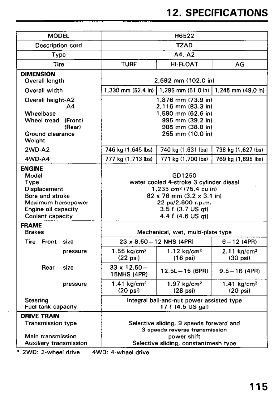
12. SPECIFICATIONS
MbDEL
H6522
Description cord
TZAD
Type
A4. A2
Tire
TURF
HI-FLOAT
AG
DIMENSION
Overall length
Overall width
Overall height-A2
-A4
Wheelbase
Wheel tread (Front)
(Rear)
Ground clearance
Weight
2WD-A2
4WD-A4
ENGINE
Model
Type
Displacement
Bore and stroke
Maximum horsepower
Engine oil capacity
Coolant capacity
2,592 mm (102.0 in)
1,330 mm (52.4 in)
1,295 mm (51 .O in)
1,245 mm (49.0 in)
1,876 mm (73.9 in)
2,116 mm (83.3 in)
1,590 mm (62.6 in)
995 mm (39.2 in)
985 mm (38.8 in)
255 mm (10.0 in)
746 kg (1,645 Ibs)
740 kg (1,631 Ibs)
738 kg (1,627 Ibs)
777 kg (1,713 Ibs) 771 kg (1,700 Ibs)
769 kg (I ,695 Ibs)
GD1250
water cooled 4-stroke 3 cylinder diesel
1,235 cm* (75.4 cu in)
82 x 78 mm (3.2 x 3.1 in)
22 ~~12,600 r.p.m.
3.5 P (3.7 us qt)
4.4 P (4.6 US qt)
FRAME
Brakes
Mechanical, wet, multi-plate type
Tire Front size
pressure
Rear size
pressure
Steering
Fuel tank capacity
DRIVE TRAIN
Transmission type
Main transmission
Auxiliary transmission
1.41 kg/cm2 1.97 kg/cm* 1.41 kg/cm2
(20 psi)
(28 psi) (20 psi)
Integral ball-and-nut power assisted type
17 P (4.5 US gal)
Selective sliding, 9 speeds forward and
3 speeds reverse transmission
power shift
Selective sliding, constantmesh type
l
2WD: 2-wheel drive 4WD: 4-wheel drive
115
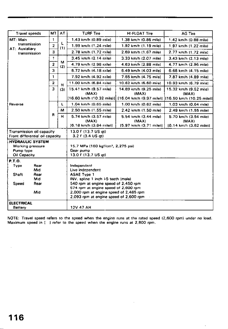
Travel speeds
ulT: Main
transmission
AT: Auxialiary
transmission
leverse
‘ransmission oil capacity
‘rant differential oil caoacitv
.
IYDRAUUC SYSTEM
Working pressure
Pump type
Oil Capacity
‘.T.D.
Type
Rear
Shaft
Speed
Mid
Rear
Mid
Rear
Mid
iLECTRlCAL
Batter4
(1
16.60 km/h (10.32 mile)1 116.04 km/h 19.97 mile)) 116.50 km/h (10.25 mile)
TURF Tire
HI-FLOAT Tire
1.43 km/h (0.89 mile) 1.36 km/h (0.86 mile)
AG Tire
1.42 km/h IO.88 mile)
1.99 km/h (1.24 mile1 1 1.92 km/h (1 .19 mile) 1 1.97 km/h (1.22 mile)
2.78 km/h Il.72 mile)
3.45 km/h (2.14 mile)
4.79 km/h (2.98 mile1
2.69 km/h (1.67 mile) 2.77 km/h (1.72 mile1
3.33 km/h (2.07 mile) 3.43 km/h (2.13 mile)
4.63 km/h (2.88 mile1 4.77 km/h (2.96 mile)
6.72 km/h (4.18 mile1 6.49 km/h (4.03 mile)
6.68 km/h (4.15 mile)
7.92 km/h (4.92 mile)
7.65 km/h (4.75 mile) 7.87 km/h (4.89 mile)
I1 .OO km/h (6.84 mile) 10.62 km/h (6.60 mile) 10.93 km/h 16.79 mile)
15.41 km/h (9.57 mile)
(MAX)
14.69 km/h (9.25 mile) 15.32 km/h (9.52 mile)
(MAX)
(MAXI
i6.18 km/h (3.84 mile)1 i5.97 km/h (3.71 mile11
f6.14 km/h (3.82 mile11
13.0 I (13.7 us qt)
3.2 I (3.4 US at)
15.7 MPa (160 kgflcm’. 2,275 psi)
Gear pump
13.0 P (13.7 us qt)
Independent
Live independent
ASAE Type 1
INV. spline 1 inch 55 teeth (male)
540 rpm at engine speed of 2,450 rpm
574 rpm at engine speed of 2,600 rpm
2,000 rpm at engine speed of 2,485 rpm
2,093 rpm at engine speed of 2,600 rpm
12V47AH
NOTE: Travel speed refers to the speed when the engine runs at the rated speed (2,600 rpm) under no load.
Maximum speed in I
I refer to the speed when the engine runs at 2,800 rpm.
116

13. WARRANTY SERVICE
Owner Satisfaction
Your satisfaction and goodwill are important to your dealer and to us. All
Honda warranty details are explained in the Distributor’s Limited Warran-
ty. Normally, any problems concerning the product will be handled by your
dealer’s service department. If you have a warranty problem that has not
been handled to your satisfaction, we suggest you take the following
action:
l Discuss your problem with a member of dealership managemert. Often
complaints can be quickly resolved at that level. If the problem has
already been reviewed with the Service Manager, contact the owner of
the dealership or the General Manager.
l If your problem still has not been resolved to your satisfaction, contact
the Power Equipment Division of American Honda Motor Co., Inc.
American Honda Motor Co., Inc.
Power Equipment Customer Service Department
P.O. Box 100021
Duluth, Georgia 30136-9421
Telephone: (404) 497-6400
We will need the following information in order to assist you:
- Your name, address, and telephone number
- Product model and serial number
- Date of Purchase
- Dealer name and address
- Nature of problem
After reviewing all the facts involved, you will be advised of what action
can be taken. Please bear in mind that your problem will likely be resolved
at the dealership, using the dealer’s facilities, equipment, and personnel,
so it is very important that your initial contact be with the dealer.
Your purchase of a Honda product is greatly appreciated by both your
dealer and American Honda Motor Co., Inc. We want to assist you in every
way possible to assure your complete satisfaction with your purchase.

Current customer service contact information:
United States, Puerto Rico, and U.S. Virgin Islands:
Honda Power Equipment dealership personnel are trained professionals. They should
be able to answer any question you may have. If you encounter a problem that your
dealer does not solve to your satisfaction, please discuss it with the dealership's
management. The Service Manager or General Manager can help. Almost all problems
are solved in this way.
If you are dissatisfied with the decision made by the dealership's management, contact
the Honda Power Equipment Customer Relations Office. You can write:
American Honda Motor Co., Inc.
Power Equipment Division
Customer Relations Office
4900 Marconi Drive
Alpharetta, GA 30005-8847
Or telephone: (770) 497-6400 M-F, 8:30 am - 7:00 pm EST
When you write or call, please provide the following information:
• Model and serial numbers
• Name of the dealer who sold the Honda power equipment to you
• Name and address of the dealer who services your equipment
• Date of purchase
• Your name, address, and telephone number
• A detailed description of the problem

MEMO
118

MEMO
119

MEMO
120
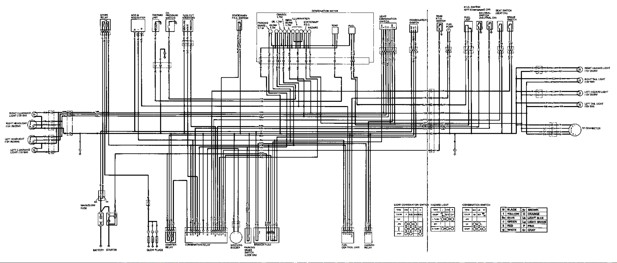
Pi
II i I lll-wt
q
=