
Printed on
Recycled Paper
O Manualwner's
KINKOS
100.2002.08
PRINTED IN U.S.A.
31763800
00X31-763-8002
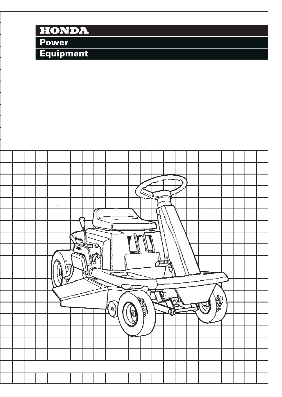
Riding Mower
H3011 • H3011H
©1989 Honda Motor Co., LTD. — All Rights Reserved


Thank you for purchasing a Honda riding mower.
This manual describes operation and maintenance of the Honda H3011
(manual transmission) and H301 1 H (hydrostatic transmission) riding
mower, type SA and HSA.
Information in this manual is based on the H301lSA model with
Mechanical Auto-clutch Transmission (MAT) except as noted. The noted
areas apply to the H3011 HSA model with Hydrostatic Transmission
(HSTI.
All information in this manual is based.on‘the latest product information
available at the time of printing.
Honda Motor Co., Ltd. reserves the right to make changes at any time
without notice and without incurring any obligation.
No part of this publication may be reproduced without written permission.
This manual is considered a permanent part of the riding mower and it
must stay with the riding mower if resold.
You can purchase an optional, U.S.D.A. qualified spark arrester for this
product from your authorized Honda Power Equipment dealer. Spark ar-
resters are required in some areas; check local laws and regulations before
operating this Honda product.
READ THIS OWNER’S MANUAL CAREFULLY. Pay special attention to
these symbols and any instructions that follow:
m
-Indicates severe personal injury or death WILL
result if instructions are not followed.
-Indicates a strong possibility of severe personal in-
jury or death if instructions are not followed.
-Indicates a possibility of personal injury or equip-
ment damage if instructions are not followed.
IMPORTANT NoTrCE -Indicates that equipment or property damage can
result if instructions are not followed.
NOTE: Gives helpful information.
Honda riding mowers are designed to give safe and dependable service if
operated according to instructions. Operating this riding mower requires
special effort on your part to ensure your safety and the safety of others.
m
Using this product for a purpose not intended may cause injury
or property damage. Use only for mowing (cutting) grass, and for bagging
cut grass when equipped with an optional grass catcher.
Read and understand this Owner’s Manual before operating the riding
mower.
If a problem should arise, or if you have any questions about your riding
mower, consult an authorized Honda riding mower dealer.
HONDA MOTOR CO., LTD. 1989, ALL RIGHTS RESERVED
1
CONTENTS
1. SAFETY INFORMATION
.......................................................
4
2. COMPONENT IDENTIFICATION
.............................................
9
3. CONTROLS
........................................................................
12
Engine switch
..................................................................... 12
Throttle lever
...................................................................... 12
Cutter deck height adjusting lever
..........................................
13
Shift lever
..........................................................................
13
Power Take-Off (P.T.O.) lever
................................................
14
Brake pedal
-
........................................................................ 15
Parking brake lever and warning buzzer
...................................
16
Transmission release lever
....................................................
18
4. PRE-OPERATION CHECKS
.................................................... 19
COOLING AIR INTAKE
......................................................... 19
ENGINE OIL
........................................................................
20
FUEL
................................................................................. 21
Fuel recommendation
........................................................... 21
GASOLINES CONTAINING ALCOHOL
.....................................
23
AIR CLEANER .....................................................................
24
BATTERY
........................................................................... 25
TRANSMISSION OIL ............................................................ 26
TRANSMISSION FLUID
........................................................
27
BRAKE
..............................................................................
27
PRIMARY BELT AND BLADE BELT ..........................................
28
TIRES
................................................................................
29
CUTTER DECK ....................................................................
29
BLADE .............................................................................. 30
SAFETY SWITCH
................................................................
32
SEAT ADJUSTMENT ........................................................... 32
5. OPERATION . . . . . . . . . . . . . . . . . . . . . . . . . . . . . . . . . . . . . . . . . . . . . . . . . . . . . . . . . . . . . . . . . . . . . . .
33
Starting the engine . . . . . . . . . . . . . . . . . . . . . . . . . . . . . . . . . . . . . . . . . . . . . . . . . . . . . . . . . . . . . .
33
Mowing . . . . . . . . . . . . . . . . . . . . . . . . . . . . . . . . . . . . . . . . . . . . . . . . . . . . . . . . . . . . . . . . . . . . . . . . . . . . .
36
Mowing tips . . . . . . . . . . . . . . . . . . . . . . . . . . . . . . . . . . . . . . . . . . . . . . . . . . . . . . . . . . . . . . . . . . . . . . .
36
Starting the riding mower
. . . . . . . . . . . . . . . . . . . . . . . . . . . . . . . . . . . . . . . . . . . . . . . . . . . . . .
38
Cutting patterns . . . . . . . . . . . . . . . . . . . . . . . . . . . . . . . . . . . . . . . . . . . . . . . . . . . . . . . . . . . . . . . . . .
40
Stopping on a hill . . . . . . . . . . . . . . . . . . . . . . . . . . . . . . . . . . . . . . . . . . . . . . . . . . . . . . . . . . . . . . . . .
42
Uphill starting procedure
. . . . . . . . . . . . . . . . . . . . . . . . . . . . . . . . . . . . . . . . . . . . . . . . . . . . . . .
42
Stopping the engine . . . . . . . . . . . . . . . . . . . . . . . . . . . . . . . . . . . . . . . . . . . . . . . . . . . . . . . . . . . . .
43
High altitude operation
. . . . . . . . . . . . . . . . . . . . . . . . . . . . . . . . . . . . . . . . . . . . . . . . . . . . . . . . .
44
6. TRANSPORTING . . . . . . . . . . . . . . . . . . . . . . . . . . . . . . . . . . . . . . . . . . . . . . . . . . . . . . . . . . . . . . . . . 45
7. MAINTENANCE . . . . . . . . . . . . . . . . . . . . . . . . . . . . . . . . . . . . . . . . . . . . . . . . . . . . . . . . . . . . . . . . . .
46
MAINTENANCE SCHEDULE
. . . . . . . . . . . . . . . . . . . . . . . . . . . . . . . . . . . . . . . . . . . . . . . . . .
47
Engine oil change . . . . . . . . . . . . . . . . . . . . . . . . . . . . . . . . . . . . . . . . . . . . . . . . . . . . . . . . . . . . . . . .
48
Air cleaner service . . . . . . . . . . . . . . . . . . . . . . . . . . . . . . . . . . . . . . . . . . . . . . . . . . . . . . . . . . . . . . .
49
Spark plug service
. . . . . . . . . . . . . . . . . . . . . . . . . . . . . . . . . . . . . . . . . . . . . . . . . . . . . . . . . . . . . . .
50
Recommended spark plug
. . . . . . . . . . . . . . . . . . . . . . . . . . . . . . . . . . . . . . . . . . . . . . . . . . . . .
50
Battery service . . . . . . . . . . . . . . . . . . . . . . . . . . . . . . . . . . . . . . . . . . . . . . . . . . . . . . . . . . . . . . . . . . . .
52
Drive clutch inspection (H301 1 only, Manual Transmission) . . . . . . . .
54
Wheel removal . . . . . . . . . . . . . . . . . . . . . . . . . . . . . . . . . . . . . . . . . . . . . . . . . . . . . . . . . . . . . . . . . . . .
55
Cutter deck removal . . . . . . . . . . . . . . . . . . . . . . . . . . . . . . . . . . . . . . . . . . . . . . . . . . . . . . . . . . . . .
56
Blade belt adjustment/replacement
. . . . . . . . . . . . . . . . . . . . . . . . . . . . . . . . . . . . . . . . .
58
Primary belt replacement . . . . . . . . . . . . . . . . . . . . . . . . . . . . . . . . . . . . . . . . . . . . . . . . . . . . . .
60
Blade bolt tightness/Blade replacement
. . . . . . . . . . . . . . . . . . . . . . . . . . . . . . . . . . .
Spark arrester maintenance
. . . . . . . . . . . . . . . . . . . . . . . . . . . . . . . . . . . . . . . . . . . . . . . . . . .
iti;
Fuse replacement . . . . . . . . . . . . . . . . . . . . . . . . . . . . . . . . . . . . . . . . . . . . . . . . . . . . . . . . . . . . . . . . .
64
8. STORAGE . . . . . . . . . . . . . . . . . . . . . . . . . . . . . . . . . . . . . . . . . . . . . . . . . . . . . . . . . . . . . . . . . . . . . . . . . .
65
Preparation for storage
. . . . . . . . . . . . . . . . . . . . . . . . . . . . . . . . . . . . . . . . . . . . . . . . . . . . . . . . .
65
Removal from storage . . . . . . . . . . . . . . . . . . . . . . . . . . . . . . . . . . . . . . . . . . . . . . . . . . . . . . . . . . 67
9. TROUBLESHOOTING
. . . . . . . . . . . . . . . . . . . . . . . . . . . . . . . . . . . . . . . . . . . . . . . . . . . . . . . . . . .
68
10. SPECIFICATIONS . . . . . . . . . . . . . . . . . . . . . . . . . . . . . . . . . . . . . . . . . . . . . . . . . . . . . . . . . . . . . . . .
72
11. WIRING DIAGRAM . . . . . . . . . . . . . . . . . . . . . . . . . . . . . . . . . . . . . . . . . . . . . . . . . . . . . . . . . . . . . .
74
12. WARRANTY SERVICE
. . . . . . . . . . . . . . . . . . . . . . . . . . . . . . . . . . . . . . . . . . . . . . . . . . . . . . . . . .
76
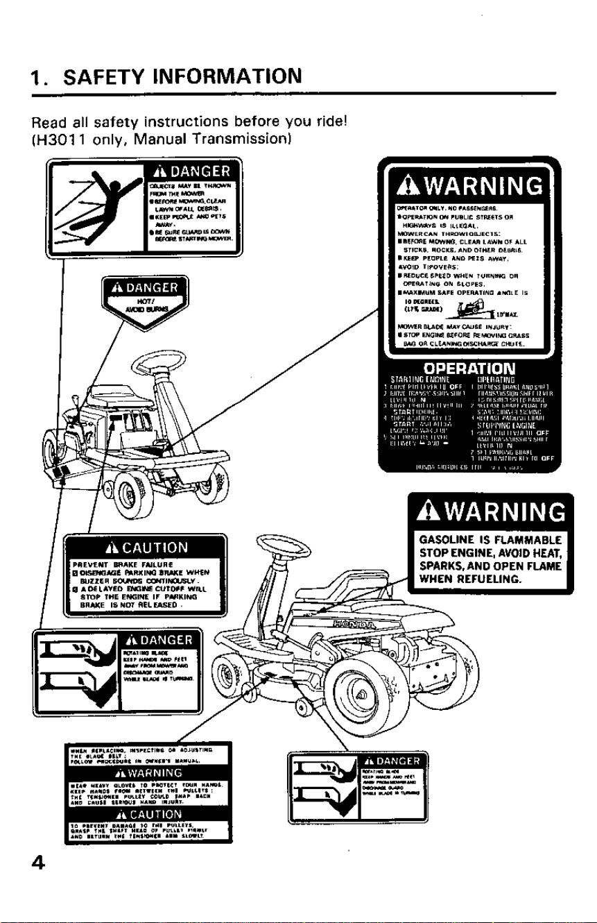
1. SAFETY INFORMATION
Read all safety instructions before you ride!
(H301 1 only, Manual Transmission)
GASOLINE IS FLAMMABLE
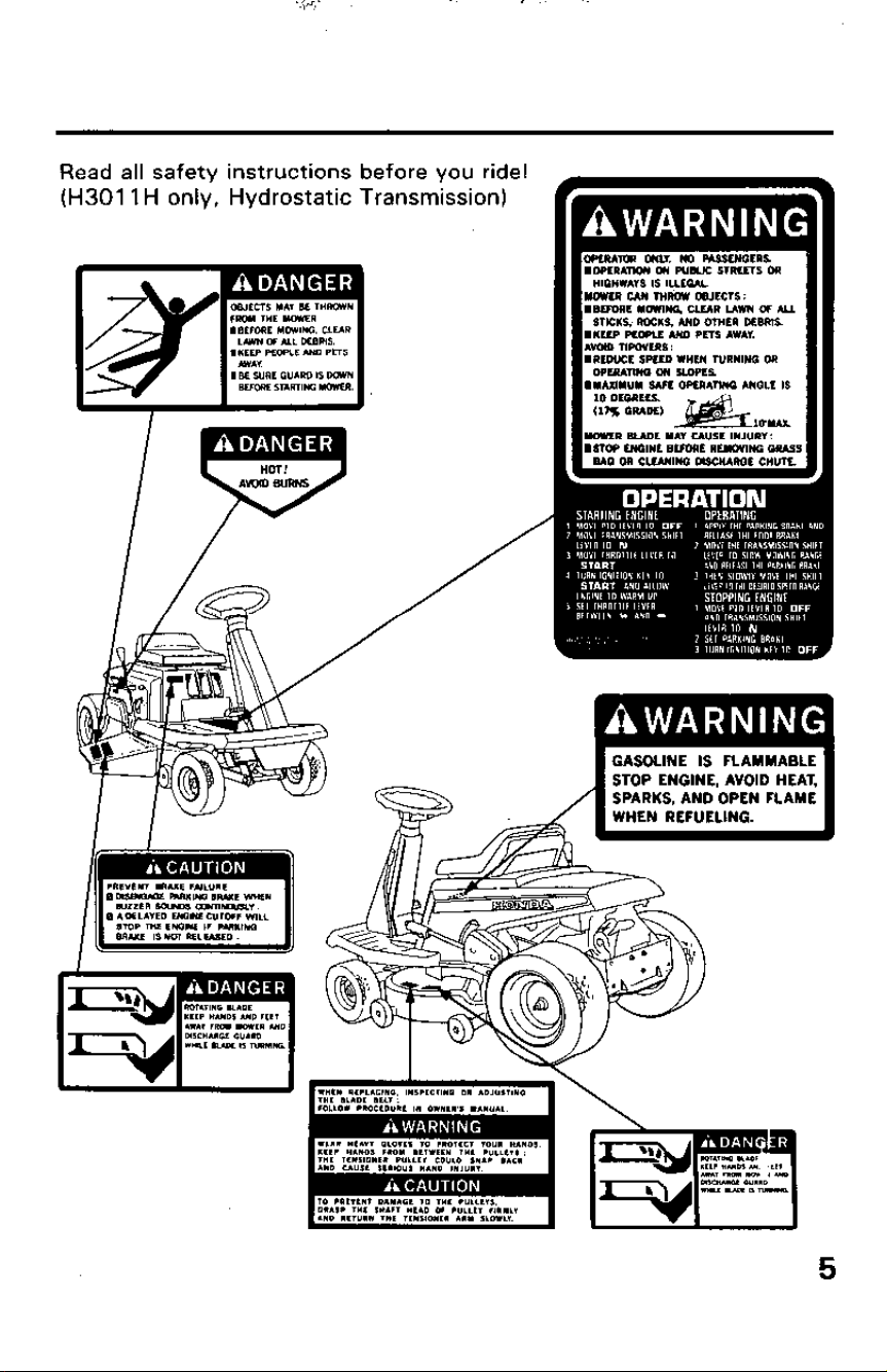
Read all safety instructions before you ride!
(H301 1 H only, Hydrostatic Transmission)
GASOLINE IS FLAMMABLE
STOP ENGINE. AVOID HEAT,
SAFETY INFORMATION
For your safety and the safety of others, pay special attention to these
precautions:
Operator Responsibility
l Keep the riding mower in good operating condition. Operating a riding
mower in poor, or questionable condition could result in serious injury.
l Be sure all safety devices are in working order and warning labels are in
place, these items are installed for your safety.
l Know how to stop the engine and blade quickly in case of emergency.
Understand the use of all controls.
l Allowing anyone, to operate this riding mower without proper instruc-
tion may result in injury.
l Allowing passengers to ride on the mower or any of its attachments
may cause the mower to tip over.
l Wear sturdy, full coverage footwear. Operating this riding mower
barefoot, or with open toe shoes or sandals increases your risk of injury.
l Dress sensibly. Loose clothing may get caught in moving parts, increas-
ing your risk of injury.
l Be alert. Operating this riding mower when you are tired, ill or under the
influence of alcohol or drugs may result in serious injury.
l Keep all persons and pets away from the mowing area.
Child Safety
Serious injury or death can occur when children fall off the mower and are
run over by the machine, or when children run or fall in the path of a
mower and are run over.
l Allowing children to ride as passengers on the riding mower can be
dangerous.
l Keep children indoors and supervised at all times when any outdoor
power equipment is being used nearby. Young children move quickly
and are attracted to the mower and the mowing activity especially if
they have been given rides before.
l Never assume children will remain where you last saw them. Be alert
and turn the mower off if children enter the area. Use extra care when
approaching corners, shrubs, and trees that might shield children from
sight.
l Children should never be allowed to operate the riding mower, even
under adult supervision.
6
-,
.
.
Cutting Blade Hazard
The cutting blade is sharp, and it turns at high speed. Accidental contact
can cause serious injury.
l Keep your hands and feet away from the mower deck while the engine
is running.
l Stop the engine, disengage the Power Take Off (P.T.O.) clutch and
remove the key before inspection or maintenance of the deck or blade.
l Disconnect the spark plug cap to prevent any possibility of accidental
starting. Wear heavy gloves to protect your hands from the blade when
cleaning out the mower deck, or when inspecting or replacing the
blade.
Thrown Object Hazard
Objects hit by the cutting blade can be thrown from the mower with great
force, and may cause serious injury.
l Before mowing, clear the mowing area of sticks, stones, dog bones,
and other litter and loose objects. Mow only in daylight, or in well-lit
areas at night, so you can see and avoid objects in the grass.
l Before operating the mower, be sure the side discharge guard is down,
or that the optional grass catcher bags and discharge chute are in place.
l Disengage the Power Take Off (P.T.O.) lever to stop the blade before
crossing a gravel driveway or any other area with loose stones.
l Always inspect the mower for damage after striking a foreign object.
Repair or replace any damaged parts before continued use.
l Broken pieces thrown from a worn or damaged blade can cause serious
injury. Always inspect the blade before using the mower.
Fire and Burn Hazard
Gasoline is extremely flammable, and gasoline vapor can explode.
Use extreme care when handling gasoline. Keep gasoline out of reach of
children.
l Refuel in a well ventilated area with the engine stopped.
l Allowed the engine to cool before refueling. Fuel vapor or spilled fuel
may ignite.
l The accumulation of dry grass and leaves around the engine or exhaust
may ignite.
l It is illegal in some areas to operate an engine without a USDA qualified
spark arrester. Periodic maintenance is required to keep it functioning
as designed.
7
The engine and exhaust system become very hot during operation and re-
main hot for a while after stopping. Contact with hot engine components
can cause burn injuries and can ignite some materials.
l Avoid touching a hot engine or exhaust system.
l Allow the engine to cool before performing maintenance or storing the
riding mower indoors.
Carbon Monoxide Poisoning Hazard
Exhaust contains poisonous carbon monoxide, a colorless and odorless
gas. Breathing exhaust can cause loss of consciousness and may lead to
death.
l If you run the engine in an area that is confined, or even partially enclos-
ed, the air you breathe could contain a dangerous amount of exhaust
gas. To keep exhaust gas from building up, provide adequate
ventilation.
Towing Hazard
Towing vehicles such as garden carts, trailers, or other vehicles is not
recommended. Towing vehicles could cause brake failure, transmission
failure or loss of control.
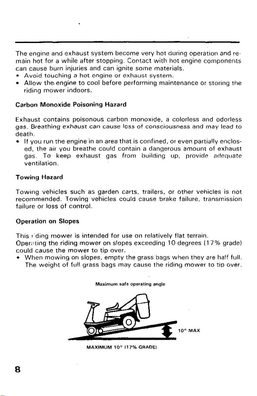
Operation on Slopes
This r‘ding mower is intended for use on relatively flat terrain.
Openlting the riding mower on slopes exceeding 10 degrees (17% grade)
could cause the mower to tip over.
l When mowing on slopes, empty the grass bags when they are half full.
The weight of full grass bags may cause the riding mower to tip over.
Maximum safe operating angle
loo MAX
MAXIMUM lOa (17% GRADE1
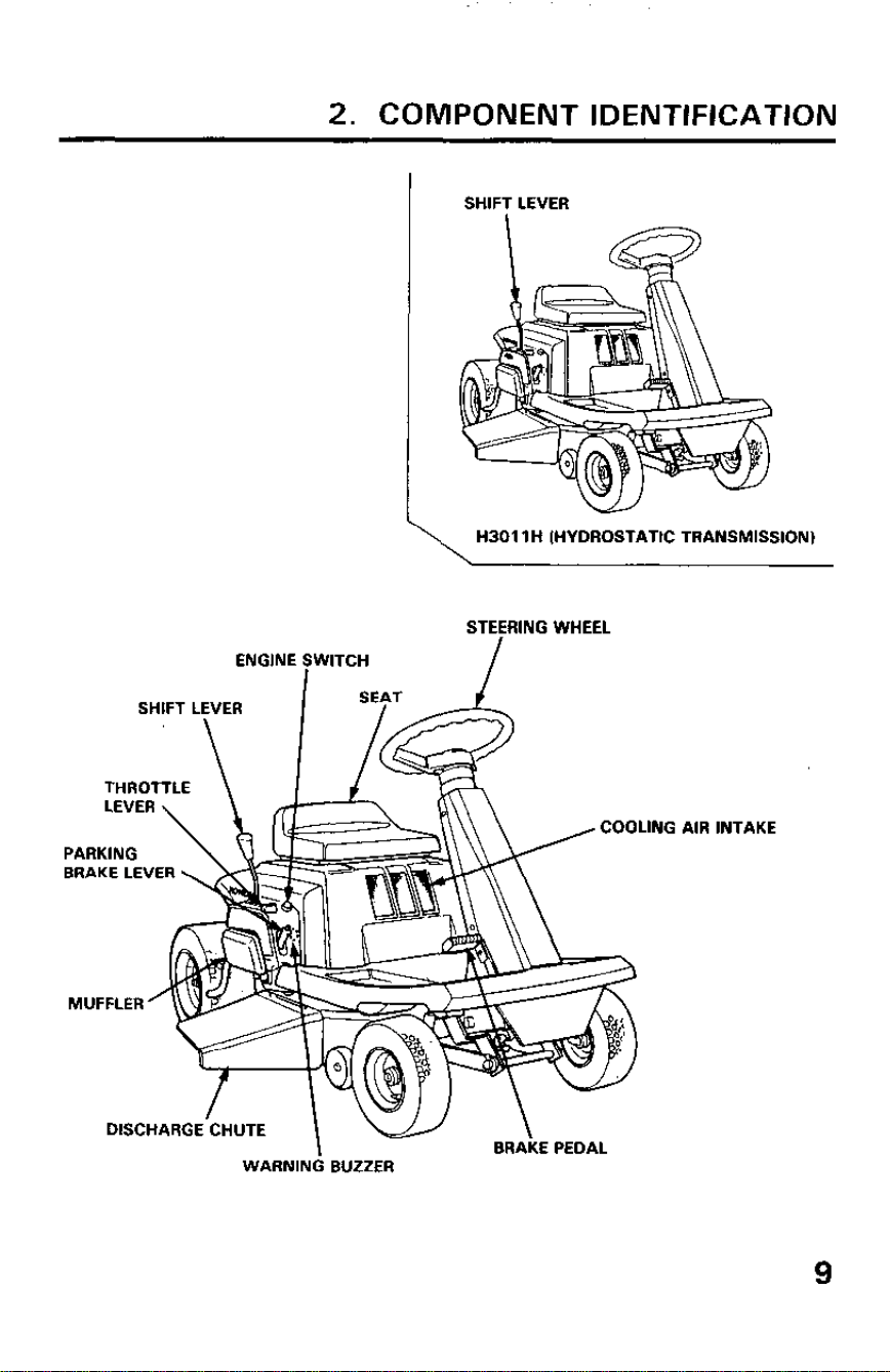
2. COMPONENT IDENTIFICATION
I
SHIFT LEVER
\
H3011H (HYDROSTATIC TRANSMISSION)
STEERING WHEEL
BRAKE LEVER
WARNING BUZZER
JNG AIR INTAKE
9
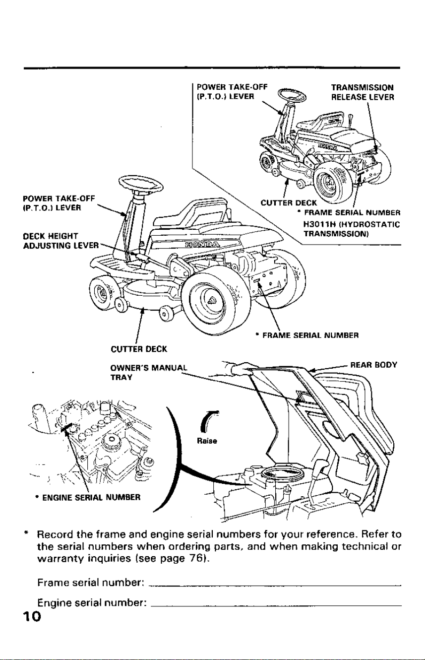
POWER TAKE-OFF
tP.T.0.) LEVER
TRANSMISSION
RELEASE LEVER
\
POWER TAKE-OFF
8.. .w ‘. . I .-.,I-” .
,I-. I .“.I LCVC”
DECK HEIGHT
ADJUSTING LE
E SERIAL NUMBER
CUTTER DECK
OWNER’S MANU
l ENGINE SERIAL NUMBER
* Record the frame and engine serial numbers for your reference. Refer to
the serial numbers when ordering parts, and when making technical or
warranty inquiries (see page 76).
Frame serial number:
Engine serial number:
IO
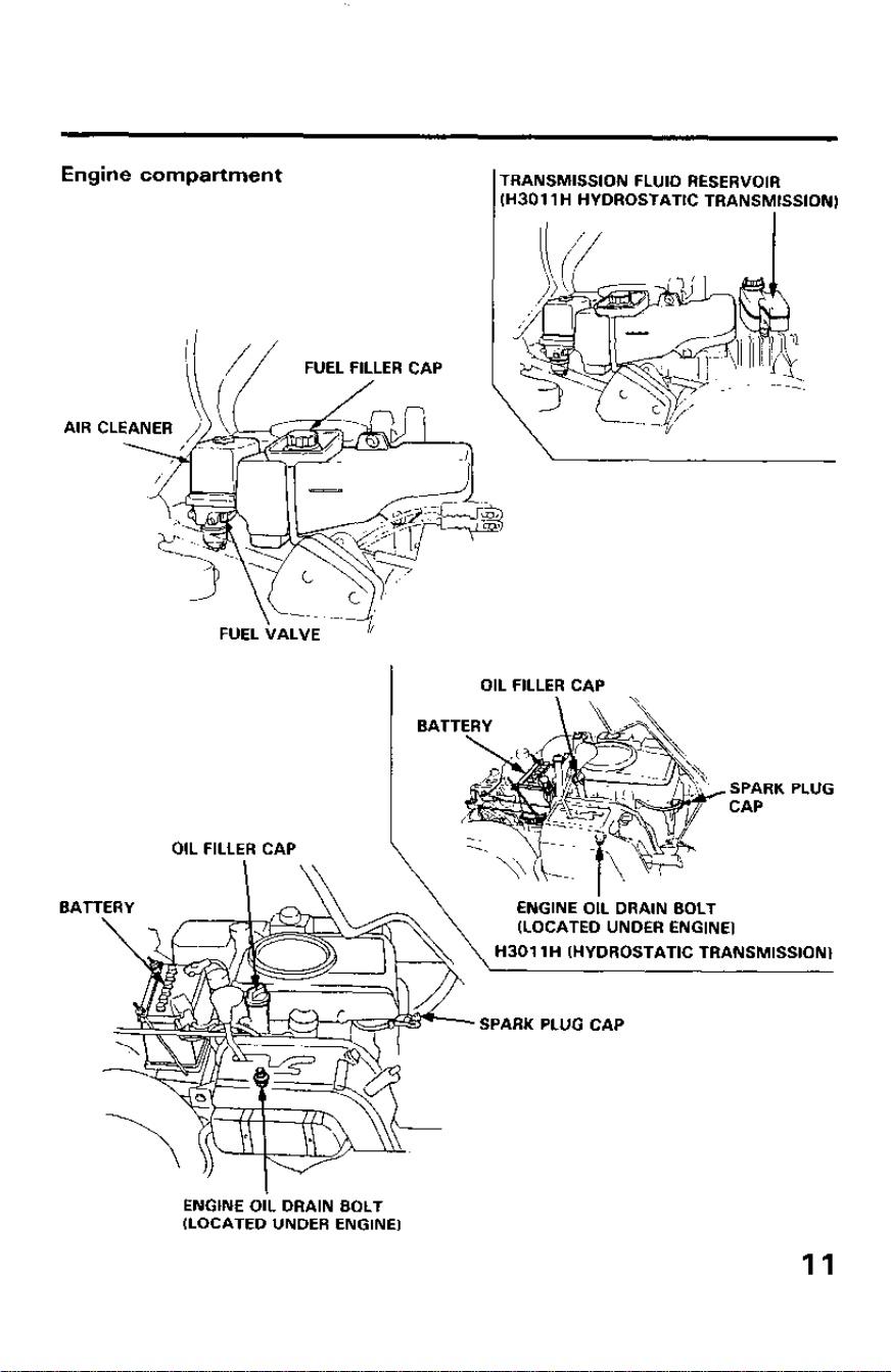
Engine compartment
TRANSMISSION FLUID RESERVOIR
lH3011H HYDROSTATIC TRANSMISSION)
AIR CLEANER
I
OIL FILLER CAP
I
1 BATTERY
SPARK PLUG
CAP
OIL FILLER CAP
BATTERY
’ %+&\ ~l?%&J%: ,“,“,:‘,E,
H3011H (HYDROSTATIC TRANSMISSION)
I??+--
SPARK PLUG CAP
-
ENGINE OIL DRAIN BOLT
(LOCATED UNDER ENGINE)
11
3. CONTROLS
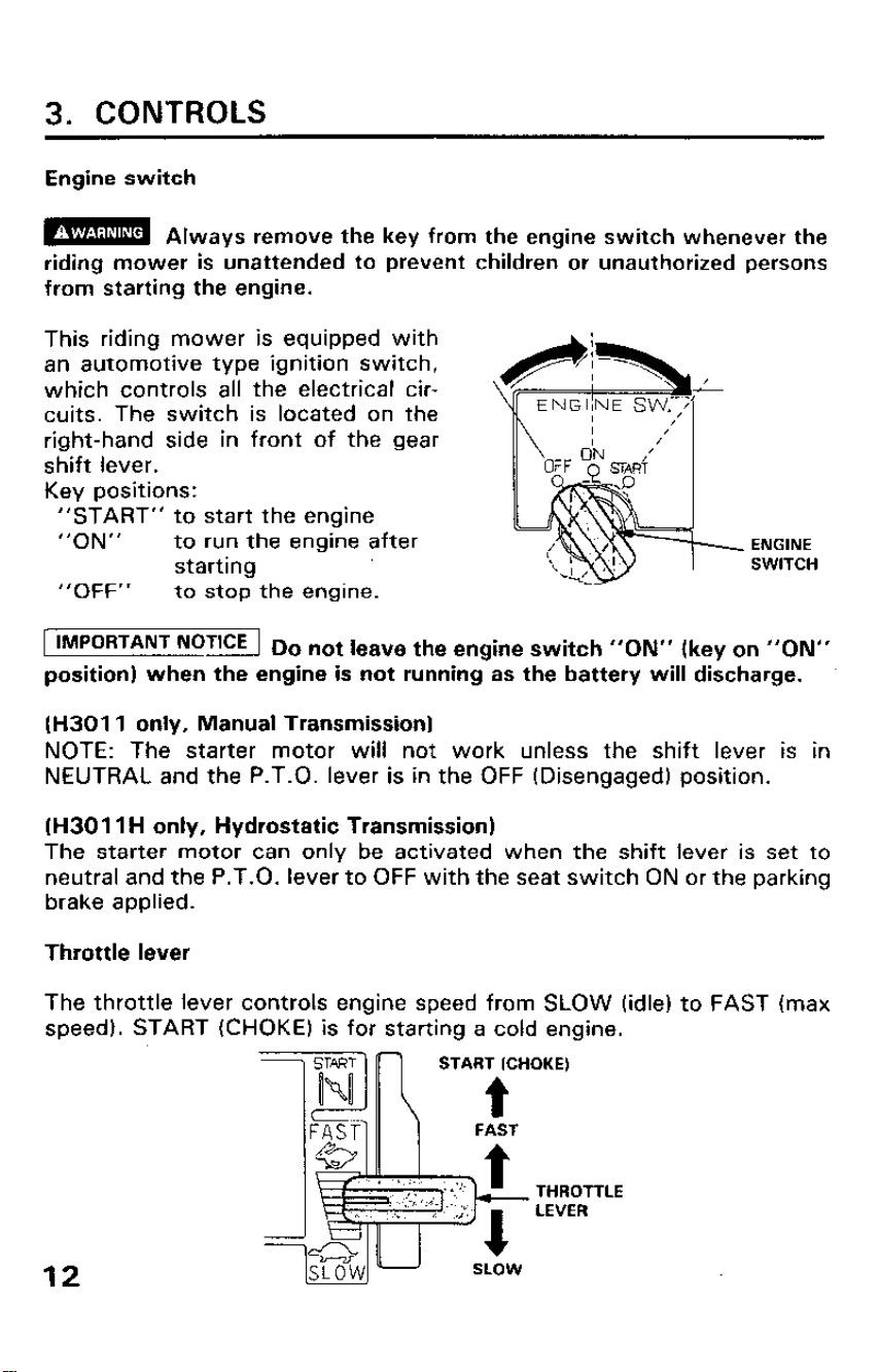
Engine switch
m Always remove the key from the engine switch whenever the
riding mower is Unattended to prevent childrenor unauthorized persons
from-starting the engine.
This riding mower is equipped with
an automotive type ignition switch,
which controls all the electrical cir-
cuits. The switch is located on the
right-hand side in front of the gear
shift lever.
Key positions:
“START” to start the engine
“ON”
to run the engine after
ENGINE
starting
SWITCH
“OFF” to stop the engine.
1 IMPORTANT NoT’CE 1 Do not leave the engine switch “ON” (key on “ON”
position) when the engine is not running as the battery will discharge.
(H3011 only, Manual Transmission)
NOTE: The starter motor will not work unless the shift lever is in
NEUTRAL and the P.T.O. lever is in the OFF (Disengaged) position.
(H3011 H only, Hydrostatic Transmission)
The starter motor can only be activated when the shift lever is set to
neutral and the P.T.O. lever to OFF with the seat switch ON or the parking
brake applied.
Throttle lever
The throttle lever controls engine speed from SLOW (idle) to FAST (max
speed). START (CHOKE) is for starting a cold engine.
12
START (CHOKE)
THROT
LEVER
TLE
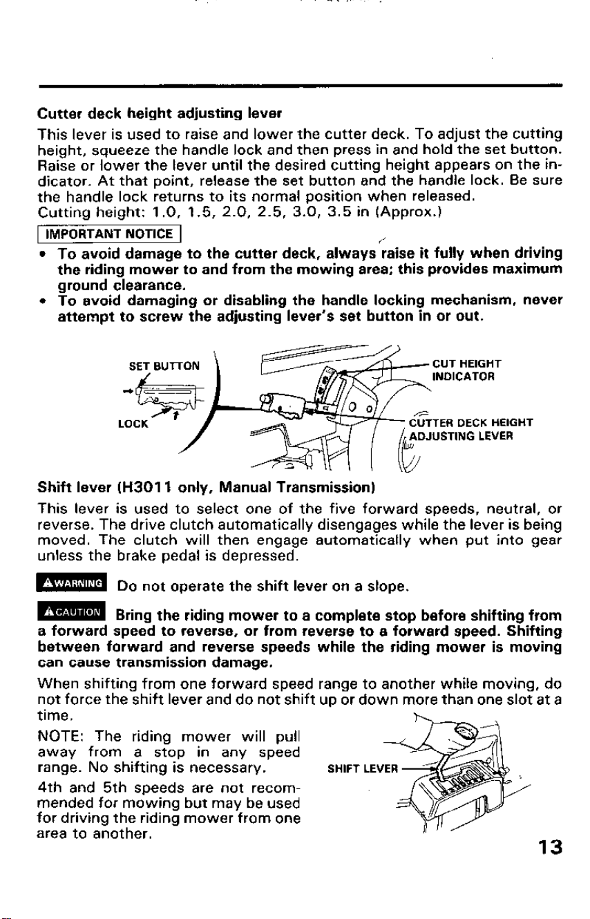
Cutter deck height adjusting lever
This lever is used to raise and lower the cutter deck. To adjust the cutting
height, squeeze the handle lock and then press in and hold the set button.
Raise or lower the lever until the desired cutting height appears on the in-
dicator. At that point, release the set button and the handle lock. Be sure
the handle lock returns to its normal position when released.
Cutting height: 1.0, 1.5, 2.0, 2.5, 3.0, 3.5 in (Approx.)
1 IMPORTANT NOTICE 1
l To avoid damage to the cutter deck, always:aise it fully when driving
the riding mower to and from the mowing area; this provides maximum
ground clearance.
l To avoid damaging or disabling the handle locking mechanism, never
attempt to screw the adjusting lever’s set button in or out.
Shift lever (H3011 only, Manual Transmission)
This lever is used to select one of the five forward speeds, neutral, or
reverse. The drive clutch automatically disengages while the lever is being
moved. The clutch will then engage automatically when put into gear
unless the brake pedal is depressed.
m
Do not operate the shift lever on a slope.
m
Bring the riding mower to a complete stop before shifting from
a forward speed to reverse, or from reverse to a forward speed. Shifting
between forward and reverse speeds while the riding mower is moving
can cause transmission damage.
When shifting from one forward speed range to another while moving, do
not force the shift lever and do not shift up or down more than one slot at a
time.
h
NOTE: The riding mower will pull
away from a stop in any speed
range. No shifting is necessary.
4th and 5th speeds are not recom-
mended for mowing but may be used
for driving the riding mower from one
area to another.
13
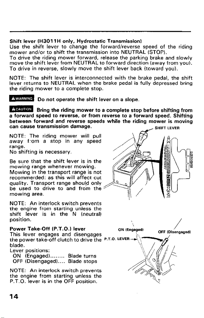
Shift lever (H3011 H only, Hydrostatic Transmission)
Use the shift lever to change the forward/reverse speed of the riding
mower and/or to shift the transmission into NEUTRAL (STOP).
To drive the riding mower forward, release the parking brake and slowly
move the shift lever from NEUTRAL to forward direction (away from you).
To drive in reverse, slowly move the shift lever back (toward you).
NOTE: The shift lever is interconnected with the brake pedal, the shift
lever returns to NEUTRAL when the brake pedal is fully depressed bring
the riding mower to a complete stop.
m
Do not operate the shift lever on a slope.
m
Bring the riding mower to a complete stop before shifting from
a forward speed to reverse, or from reverse to a forward speed. Shifting
between forward and reverse speeds while the riding mower is moving
can cause transmission damage.
SHIFT LEVER
NOTE: The riding mower will pull
away f.-om a stop in any speed
range.
No shifting is necessary.
Be sure that the shift lever is in the
mowing range whenever mowing.
Mowing in the transport range is not
recommerded: as this will affect cut
quality. Transport range shou!d only
be used to drive to and from the
mowing area.
NOTE: An interlock switch prevents
the engine from starting unless the
shift lever is in the N (neutral)
position.
Power Take-Off (P.T.O.1 lever
ON (Engaged)
/
This lever engages and disengages
OFF IDisengaged)
the power take-off clutch to drive the P.r.0.
blade.
Lever positions:
ON (Engaged) . . . . . . . . Blade turns
OFF (Disengaged). . . . Blade stops
NOTE: An interlock switch prevents
the engine from starting unless the
P.T.O. lever is in the OFF position.
14
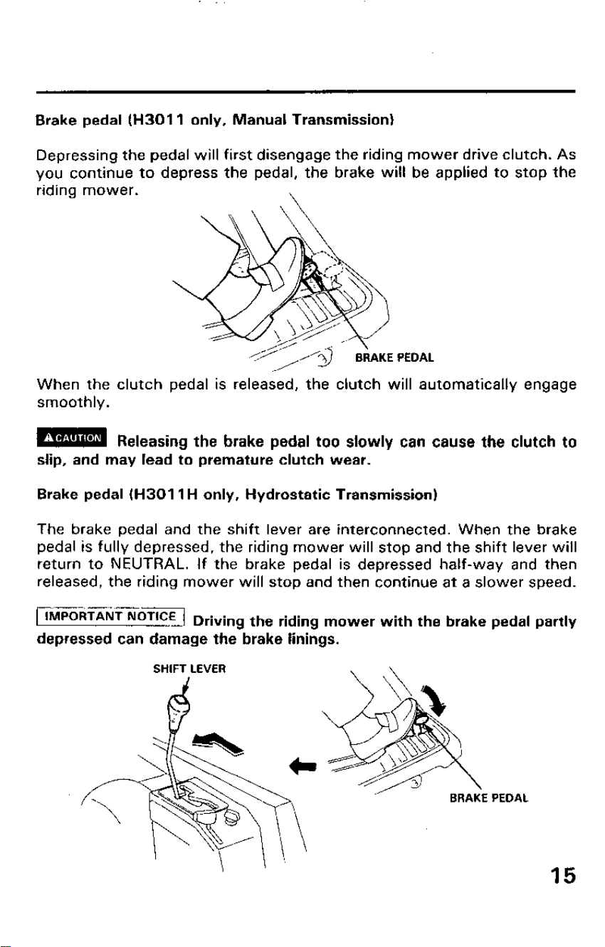
Brake pedal (H3011 only, Manual Transmission)
Depressing the pedal will first disengage the riding mower drive clutch. As
you continue to depress the pedal, the brake will be applied to stop the
riding mower.
\
When the clutch pedal is released, the clutch will automatically engage
smoothly.
m Releasing the brake pedal too slowly can cause the clutch to
slip, and may lead to premature clutch wear.
Brake pedal (H3011 H only, Hydrostatic Transmission)
The brake pedal and the shift lever are interconnected. When the brake
pedal is fully depressed, the riding mower will stop and the shift lever will
return to NEUTRAL. If the brake pedal is depressed half-way and then
released, the riding mower will stop and then continue at a slower speed.
IMPORTANT NoT’CE Driving the riding mower with the brake pedal partly
depressed can damage the brake linings.
PEDAL
15
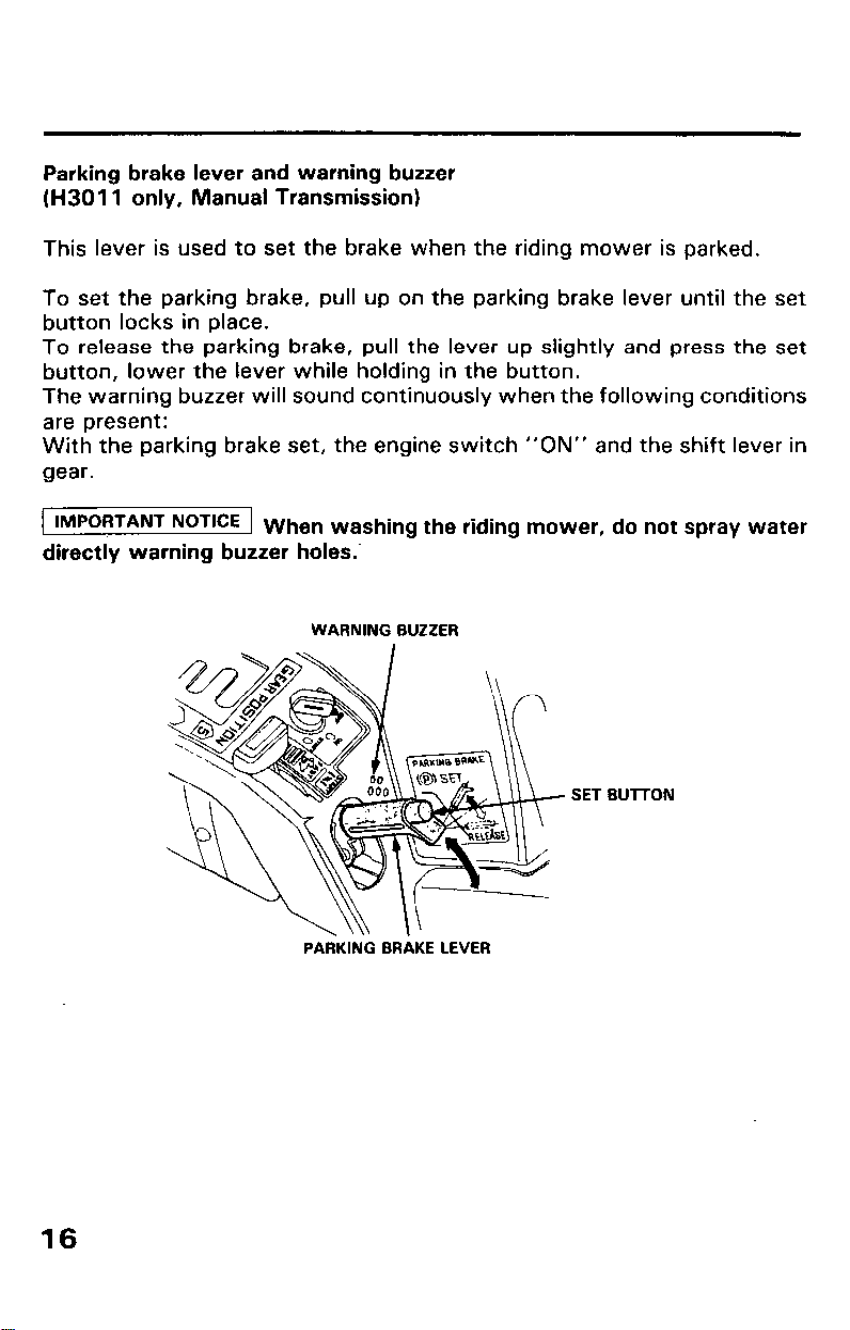
Parking brake lever and warning buzzer
(H3011 only, Manual Transmission)
This lever is used to set the brake when the riding mower is parked.
To set the parking brake, pull up on the parking brake lever until the set
button locks in place.
To release the parking brake, pull the lever up slightly and press the set
button, lower the lever while holding in the button.
The warning buzzer will sound continuously when the following conditions
are present:
With the parking brake set, the engine switch “ON” and the shift lever in
gear.
lMPORTANT NOTKE When washing the riding mower, do not spray water
directly warning buzzer holes:
WARNING BUZZER
SET BUTTON
PARKING BRAKE LEVER
16
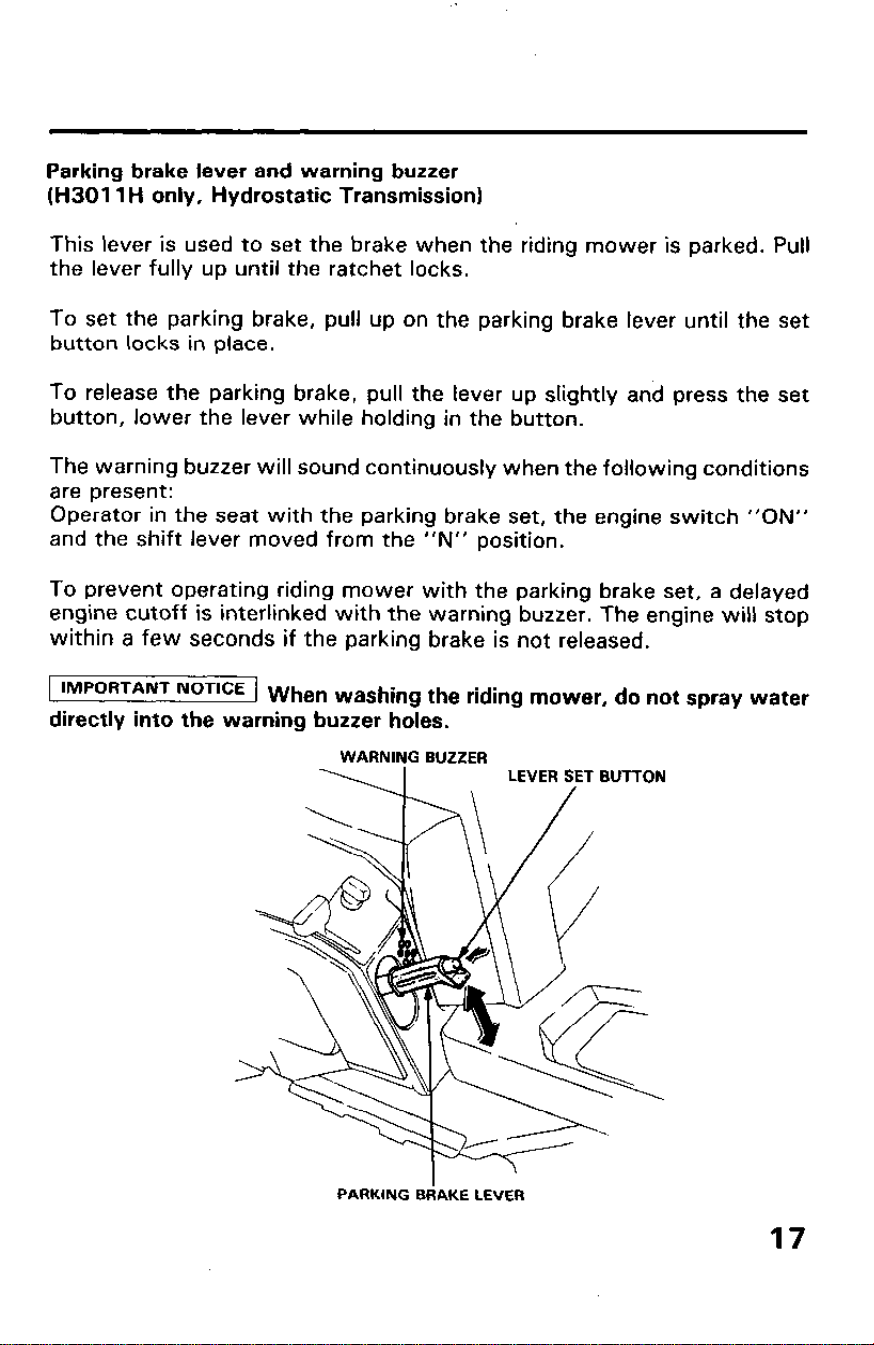
Parking brake lever and warning buzzer
(H3011 H only, Hydrostatic Transmission)
This lever is used to set the brake when the riding mower is parked. Pull
the lever fully up until the ratchet locks.
To set the parking brake, pull up on the parking brake lever until the set
button locks in place.
To release the parking brake, pull the lever up slightly and press the set
button, lower the lever while holding in the button.
The warning buzzer will sound continuously when the following conditions
are present:
Operator in the seat with the parking brake set, the engine switch “ON”
and the shift lever moved from the “N” position.
To prevent operating riding mower with the parking brake set, a delayed
engine cutoff is interlinked with the warning buzzer. The engine will stop
within a few seconds if the parking brake is not released.
) IMPORTANT NOTICE 1
“,,,,
en
washing the riding mower, do not spray water
directly into the warning buzzer holes.
PARKING BdAKE LEVER
17
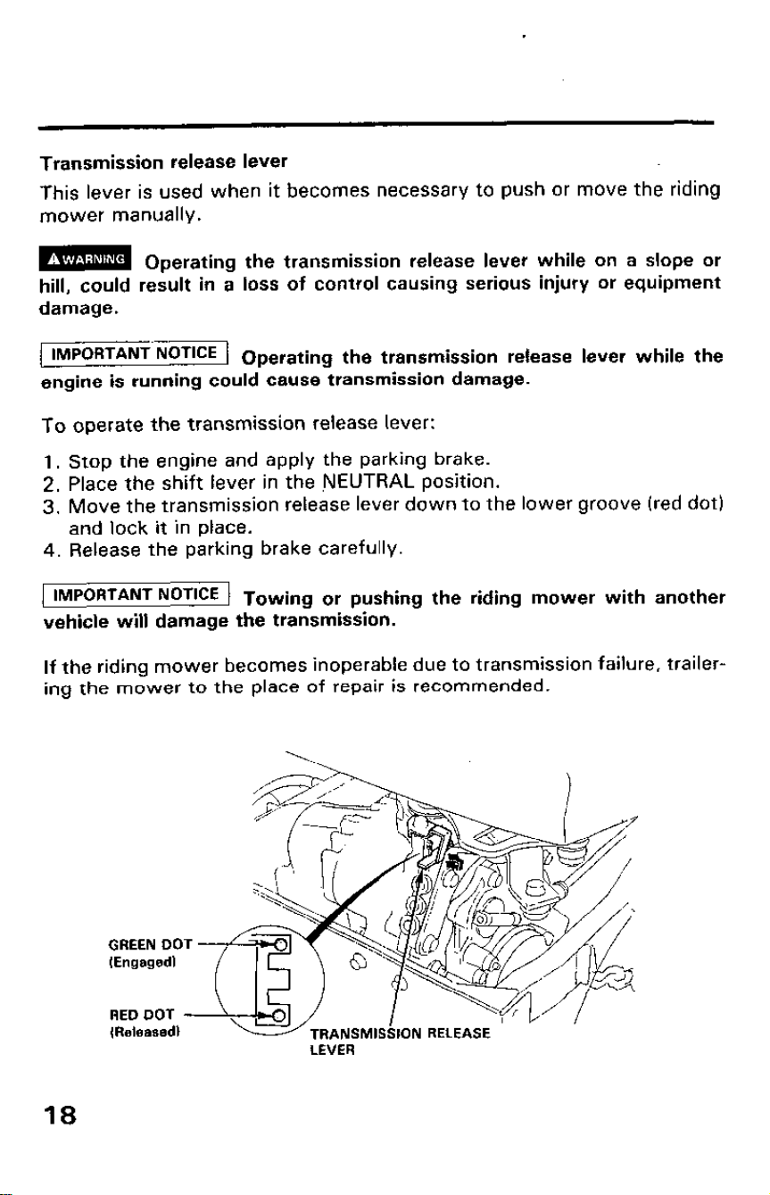
Transmission release lever
This lever is used when it becomes necessary to push or move the riding
mower manually.
m
Operating the transmission release lever while on a slope or
hill, could result in a loss of control causing serious injury or equipment
damage.
[ IMPORTANT NoT’CE 1 Operating the transmission release lever while the
engine is running could cause transmission damage.
To operate the transmission release lever:
1.
2.
3.
4.
Stop the engine and apply the parking brake.
Place the shift lever in the NEUTRAL position.
Move the transmission release lever down to the lower groove (red dot)
and lock it in place.
Release the parking brake carefully.
IMPORTANT NoTCE 1 Towing or pushing the riding mower with another
vehicle will damage the transmission.
If the riding mower becomes inoperable due to transmission failure, trailer-
ing the mower to the place of repair is recommended.
LEVER
18
4. PRE-OPERATION CHECKS
Following the procedures below ‘and check all of the following items
before each use:
1. Park the riding mower on a level surface.
2. Place the shift lever in the neutral position and set the park brake.
3. Disconnect the spark plug cap and remove the engine switch key to
prevent accidental engine start-up.
m
If the engine is started accidentally while you are performing
the pre-operation checks, moving parts may cause serious injury.
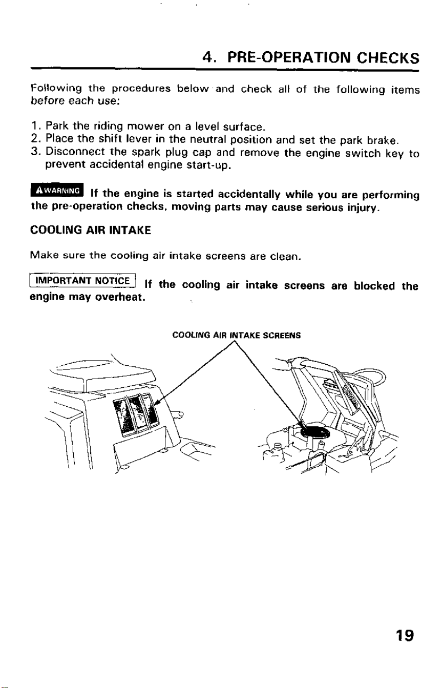
COOLING AIR INTAKE
Make sure the cooling air intake screens are clean.
IMPORTANT NOTICE
1 If the cooling air intake screens are blocked the
engine may overheat.
COOLING AIR INTAKE SCREENS
19
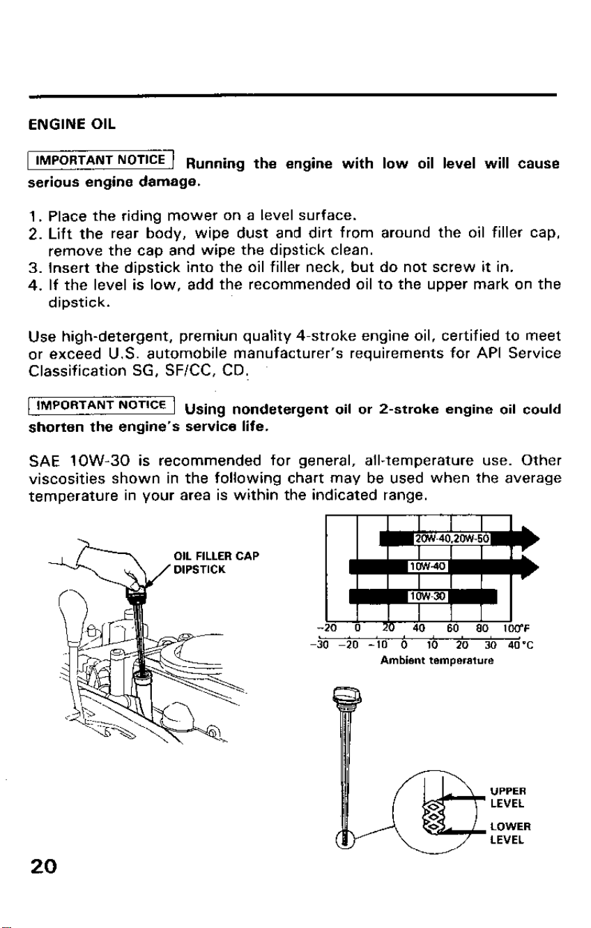
ENGINE OIL
IMPORTANT NOTICE
1 Running the engine with low oil level will cause
serious engine damage.
1. Place the riding mower on a level surface.
2. Lift the rear body, wipe dust and dirt from around the oil filler cap,
remove the cap and wipe the dipstick clean.
3. Insert the dipstick into the oil filler neck, but do not screw it in.
4. If the level is low, add the recommended oil to the upper mark on the
dipstick.
Use high-detergent, premiun quality 4-stroke engine oil, certified to meet
or exceed U.S. automobile manufacturer’s requirements for API Service
Classification SG, SF/CC, CD.
IMPORTANT NOTICE
IMPORTANT NoT’CE 1 Using nondetergent oil or P-stroke engine oil could 1 Using nondetergent oil or P-stroke engine oil could
shorten the engine’s service life. shorten the engine’s service life.
SAE low-30 is recommended for general, all-temperature use. Other SAE low-30 is recommended for general, all-temperature use. Other
viscosities shown in the following chart may be used when the average viscosities shown in the following chart may be used when the average
temperature in your area is within the indicated range. temperature in your area is within the indicated range.
OIL FILLER CAP OIL FILLER CAP
-30 -20 -10 -30 -20 -10 0 0 10 10
20 20 30 4O’C 30 4O’C
Ambient temperature Ambient temperature
UPPER UPPER
LEVEL LEVEL
LOWER LOWER
LEVEL LEVEL
20
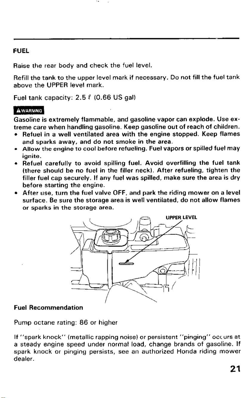
FUEL
Raise the rear body and check the fuel level.
Refill the tank to the upper level mark if necessary. Do not fill the fuel tank
above the UPPER level mark.
Fuel tank capacity: 2.5 P (0.66 US gal)
Gasoline is extremely flammable, and gasoline vapor can explode. Use ex-
treme care when handling gasoline. Keep gasoline out of reach of children.
l Refuel in a well ventilated area with the engine stopped. Keep flames
and sparks away, and do not smoke in the area.
- Allow the engine to cool before refueling. Fuel vapors or spilled fuel may
ignite.
l Refuel carefully to avoid spilling fuel. Avoid overfilling the fuel tank
(there should be no fuel in the filler neck). After refueling, tighten the
filler fuel cap securely. If any fuel was spilled, make sure the area is dry
before starting the engine.
l After use, turn the fuel valve OFF, and park the riding mower on a level
surface. Be sure the storage area is well ventilated, do not allow flames
or sparks in the storage area.
Fuel Recommendation
Pump octane rating: 86 or higher
If “spark knock” (metallic rapping noise) or persistent “pinging” occurs at
a steady engine speed under normal load, change brands of gasoline. If
spark knock or pinging persists, see an authorized Honda riding mower
dealer.
21
IMPORTANT NoT’CE Running the engine with persistent spark knock or
pinging can cause engine damage.
Running the engine with persistent spark knock or pinging is considered
misuse, and the Distributor’s Limited Warranty does not cover parts
damaged by misuse.
Occasionally you may hear light spark knock while operating under heavy
loads. This is no cause for concern. It simply means your engine is
operating efficiently.
We recommend unleaded fuel because it produces fewer engine and spark
plug deposits and extends the exhaust system life.
Never use stale or contaminated gasoline or an oil/gasoline mixture. Avoid
getting dirt or water in the fuel tank.
22
GASOLINES CONTAINING ALCOHOL
If you decide to use a gasoline containing alcohol (gasohol), be sure its
rating is at least as high as that recommended by Honda (see Fuel Recom-
mendation on page 21). There are two types of “gasohol”: one containing
ethanol, and the other containing methanol.
m
Using gasohol that contains more than 10% ethanol, or
gasoline containing methanol (methyl or wood alcohol) that does not also
contain cosolvents and corrosion inhibitors for methanol, can cause
serious fuel system damage and poor engine performance.
Never use gasoline containing more than 5% methanol, even if it has
cosolvents and corrosion inhibitors.
Honda cannot endorse the use of fuels containing methanol since
evidence of their suitability is as yet incomplete.
NOTE: Fuel system damage or engine performance problems resulting
from the use of fuels that contain alcohol is not covered under the
warranty.
Before buying fuel from an unfamiliar station, first determine if the fuel
contains alcohol; if it does, find out the type and percentage of alcohol
used.
NOTE: If you notice any undesirable operating symptoms while using a
gasoline that contains alcohol, or one that you think contains alcohol,
switch to a gasoline that you know does not contain alcohol.
23
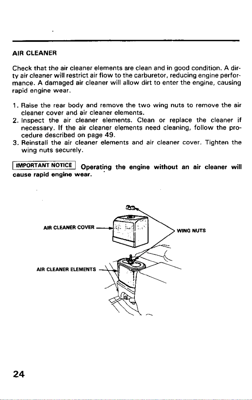
AIR CLEANER
Check that the air cleaner elements are clean and in good condition. A dir-
ty air cleaner will restrict air flow to the carburetor, reducing engine perfor-
mance. A damaged air cleaner will allow dirt to enter the engine, causing
rapid engine wear.
1. Raise the rear body and remove the two wing nuts to remove the air
cleaner cover and air cleaner elements.
2. Inspect the air cleaner elements.
Clean or replace the cleaner if
necessary. If the air cleaner elements need cleaning, follow the pro-
cedure described on page 49.
3. Reinstall the air cleaner elements and air cleaner cover. Tighten the
wing nuts securely.
1 lMPORTANT NoTtCE 1 Operatirig the engine without an air cleaner will
cause rapid engine wear. ’
AIR CLEANER COVER
AIR CLEANER ELEMENTS
NUTS
24
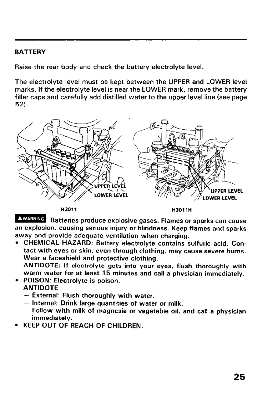
BATTERY
Raise the rear body and check the battery electrolyte level.
The electrolyte level must be kept between the UPPER and LOWER level
marks. If the electrolyte level is near the LOWER mark, remove the battery
filler caps and carefully add distilled water to the upper level line (see page
52).
Ii301 1
H3011H
m
Batteries produce explosive gases. Flames or sparks can cause
an explosion, causing serious injury or blindness. Keep flames and sparks
away and provide adequate ventilation when charging.
l CHEMICAL HAZARD: Battery electrolyte contains sulfuric acid. Con-
tact with eyes or skin, even through clothing, may cause severe burns.
Wear a faceshield and protective clothing.
ANTIDOTE: If electrolyte gets into your eyes, flush thoroughly with
warm water for at least 15 minutes and call a physician immediately.
l POISON: Electrolyte is poison.
ANTIDOTE
- External: Flush thoroughly with water.
- Internal: Drink large quantities of water or milk.
Follow with milk of magnesia or vegetable oil, and call a physician
immediately.
l KEEP OUT OF REACH OF CHILDREN.
25
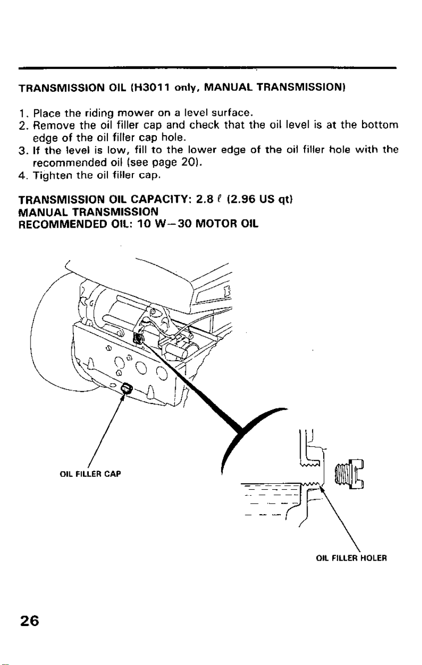
TRANSMISSION OIL (H3011 only, MANUAL TRANSMISSION)
1. Place the riding mower on a level surface.
2. Remove the oil filler cap and check that the oil level is at the bottom
edge of the oil filler cap hole.
3. If the level is low, fill to the lower edge of the oil filler hole with the
recommended oil (see page 20).
4. Tighten the oil filler cap.
TRANSMISSION OIL CAPACITY: 2.8 P (2.96 US qtl
MANUAL TRANSMISSION
RECOMMENDED OIL: 10 W-30 MOTOR OIL
OIL FILLER‘HOLER
26
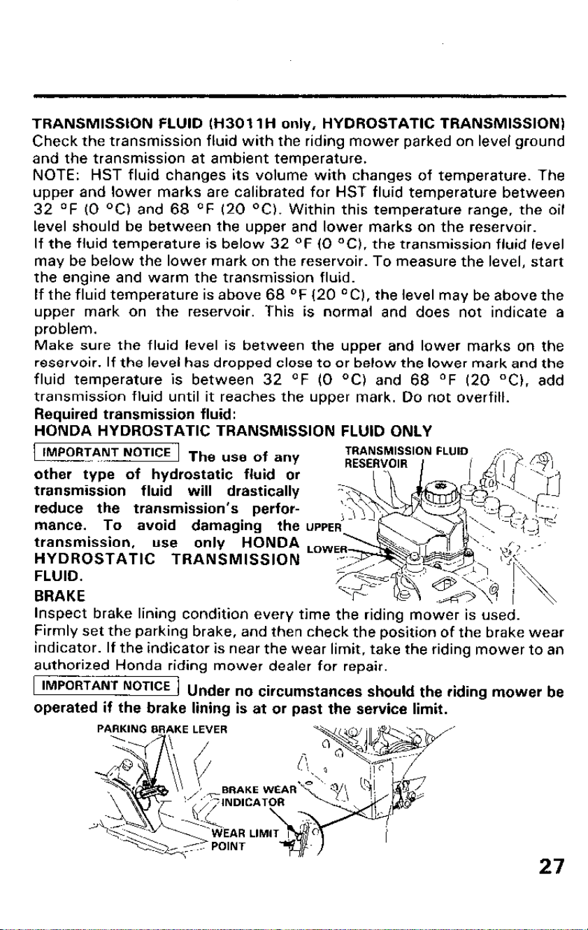
TRANSMISSION FLUID (H3011 H only, HYDROSTATIC TRANSMISSION)
Check the transmission fluid with the riding mower parked on level ground
and the transmission at ambient temperature.
NOTE: HST fluid changes its volume with changes of temperature. The
upper and lower marks are calibrated for HST fluid temperature between
32 OF (0 OC) and 68 OF (20 “Cl. Within this temperature range, the oil
level should be between the upper and lower marks on the reservoir.
If the fluid temperature is below 32 OF (0 OC), the transmission fluid level
may be below the lower mark on the reservoir. To measure the level, start
the engine and warm the transmission fluid.
If the fluid temperature is above 68 OF (20 OC), the level may be above the
upper mark on the reservoir. This is normal and does not indicate a
problem.
Make sure the fluid level is between the upper and lower marks on the
reservoir. If the level has dropped close to or below the lower mark and the
fluid temperature is between 32
OF (0 OC) and 68 OF (20 OC), add
transmission fluid until it reaches the upper mark. Do not overfill.
Required transmission fluid:
HONDA HYDROSTATIC TRANSMISSION FLUID ONLY
TRANSMISSION FLUID
RESERVOIR I
IMPORTANT NOTICE The uSe of any
other type of hydrostatic fluid or
transmission fluid will drastically
reduce the transmission’s perfor-
mance.
To avoid damaging the
transmission,
use only HONDA
HYDROSTATIC TRANSMISSION
FLUID.
BRAKE
Inspect brake lining condition every time the riding mower is used.
Firmly set the parking brake, and then check the position of the brake wear
indicator. If the indicator is near the wear limit, take the riding mower to an
authorized Honda riding mower dealer for repair.
IMPORTANT NOTICE 1 u
n er no circumstances should the riding mower be
,,
operated if the brake lining is at or past the service limit.
27
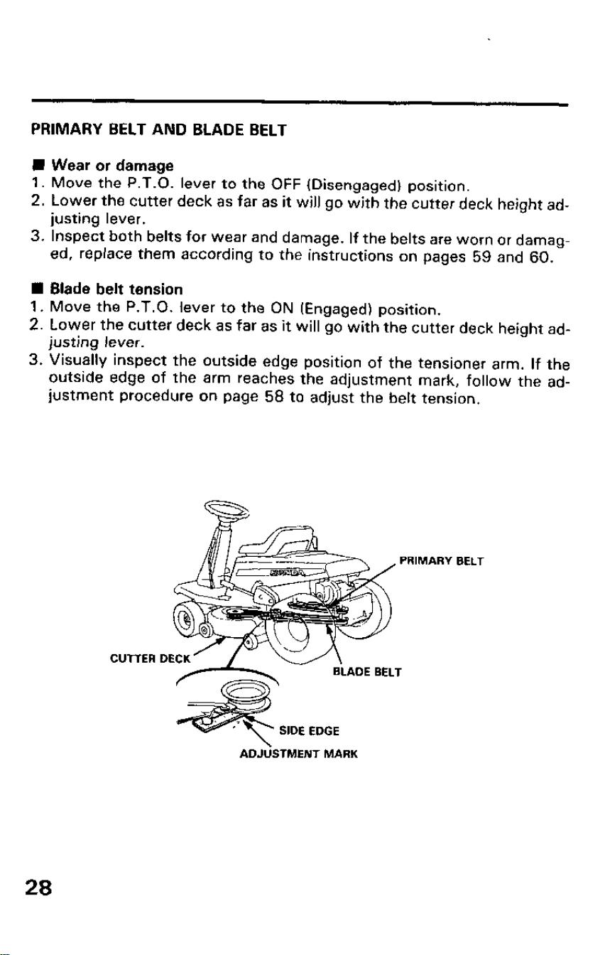
PRIMARY BELT AND BLADE BELT
n Wear or damage
1. Move the P.T.O. lever to the OFF (Disengaged) position.
2. Lower the cutter deck as far as it will go with the cutter deck height ad-
justing lever.
3. Inspect both belts for wear and damage. If the belts are worn or damag-
ed, replace them according to the instructions on pages 59 and 60.
n Blade belt tension
1. Move the P.T.O. lever to the ON (Engaged) position.
2. Lower the cutter deck as far as it will go with the cutter deck height ad-
justing lever.
3. Visually inspect the outside edge position of the tensioner arm. If the
outside edge of the arm reaches the adjustment mark, follow the ad-
justment procedure on page 58 to adjust the belt tension.
BELT
ADJlkTMENT MARK
28
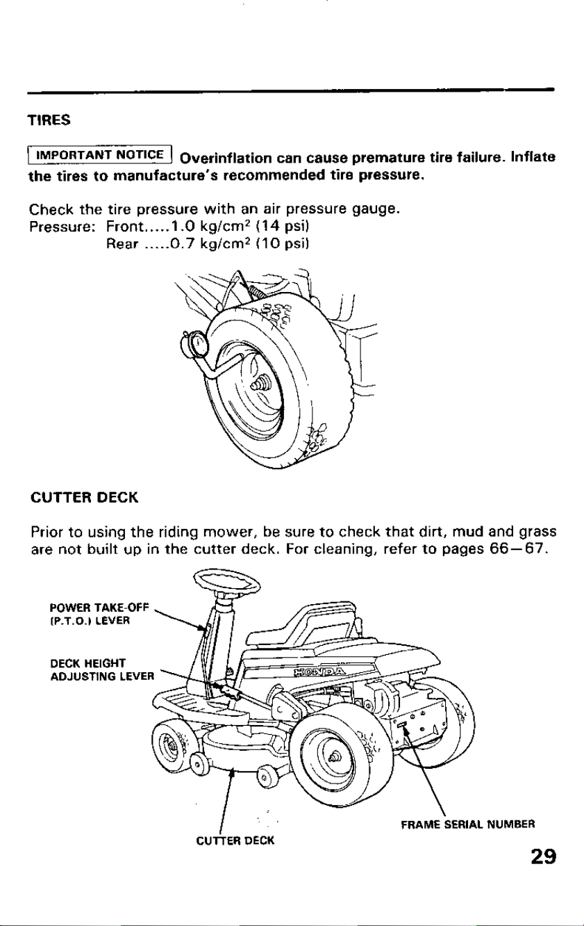
TIRES
IMPORTANT NoTKZE Overinflation can cause premature tire failure. Inflate
the tires to manufacture’s recommended tire pressure.
Check the tire pressure with an air pressure gauge.
Pressure: Front.. . . . 1 .O kg/cm2 (14 psi)
Rear . . ...0.7 kg/cm* (10 psi)
CUTTER DECK
Prior to using the riding mower, be sure to check that dirt, mud and grass
are not built up in the cutter deck. For cleaning, refer to pages 66-67.
POWER TAKE-OFF
(P.T.0.) LEVER
DECK HEIGHT
ADJUSTING LEVER
‘I .:
-
\
FRAME SERIAL
CUTTER DECK
NUMBER
29
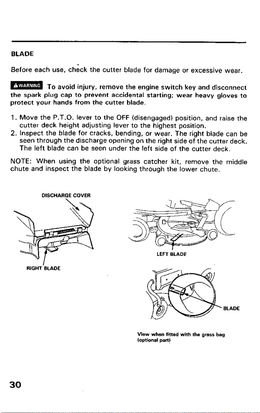
BLADE
Before each use, check the cutter blade for damage or excessive wear.
m To avoid injury, remove the engine switch key and diSCOnnBCt
the spark plug cap to prevent accidental starting; wear heavy gloves to
protect your hands from the cutter blade.
1. Move the P.T.O. lever to the OFF (disengaged) position, and raise the
cutter deck height adjusting lever to the highest position.
2. Inspect the blade for cracks, bending, or wear. The right blade can be
seen through the discharge opening on the right side of the cutter deck.
The left blade can be seen under the left side of the cutter deck.
NOTE: When using the optional grass catcher kit, remove the middle
chute and inspect the blade by looking through the lower chute.
DISCHARGE COVER
RIGHT’BLADE
BLADE
View when fitted with the grass bag
(optional part)
30

4. If the blade shows signs of damage or excessive wear, a more thorough
inspection is necessary (see page 56 for cutter deck removal). A dull
blade can be sharpened, but a blade that is worn out, bent, cracked or
otherwise damaged must be replaced. If a blade needs sharpening or
replacement, take the cutter deck to your authorized Honda riding
mower dealer.
Or, if you have the proper tools, you can remove and install the blade
yourself.
-7 \ ._. .-. --
-r\ BENT Zig-~J
CRACKED
----. i..._!..--
m
Broken piece thrown from a worn or damaged blade can cause
serious injury. Always inspect the blade before using the mower.
1 IMPORTANT NOTICE 1
l Use a genuine Honda replacement blade, or equivalent.
l To reduce the possibility of weakening the blade, or causing imbalance
or poor cutting performance, sharpening should be performed by an
authorized Honda riding mower dealer.
31
SAFETY SWITCH
Before performing these inspections, remove the spark plug cap.
1. P.T.O. switch inspection
l With the shift lever in the N (Neutral) position, set the P.T.O. lever in
the ON (Engaged position).
l Check that the starter motor is not started when the engine switch is
turned to the START position.
l Return the P.T.O. lever to the OFF (Disengaged) position.
2. Neutral switch inspection
l With the P.T.O. lever in the OFF (Disengaged) position, move the
shift lever from the “N” (Neutral) position into a gear or speed range.
l Check that the starter motor is not started when the engine switch is
turned to the START position.
l Return the shift lever to the N (Neutral) position and reinstall the
spark plug cap.
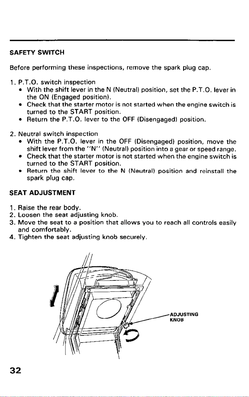
SEAT ADJUSTMENT
1.
2.
3.
4.
Raise the rear body.
Loosen the seat adjusting knob.
Move the seat to a position that allows you to reach all controls easily
and comfortably.
Tighten the seat adjusting knob securely.
ADJUSTING
KNOB
32
5. OPERATION
Starting the engine
m
Exhaust gas contains poisonous carbon monoxide gas that
may cause loss of consciousness and lead to death. Never run the engine
in an enclosed area. Be sure to provide adequate ventilation.
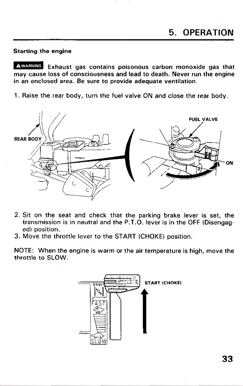
1. Raise the rear body, turn the fuel valve ON and close the rear body.
REAR
ON
2. Sit on the seat and check that the parking brake lever is set, the
transmission is in neutral and the P.T.O. lever is in the OFF (Disengag-
ed) position.
3. Move the throttle lever to the START (CHOKE) position.
NOTE: When the engine is warm or the air temperature is high, move the
throttle to SLOW.
START (CHOKE)
33
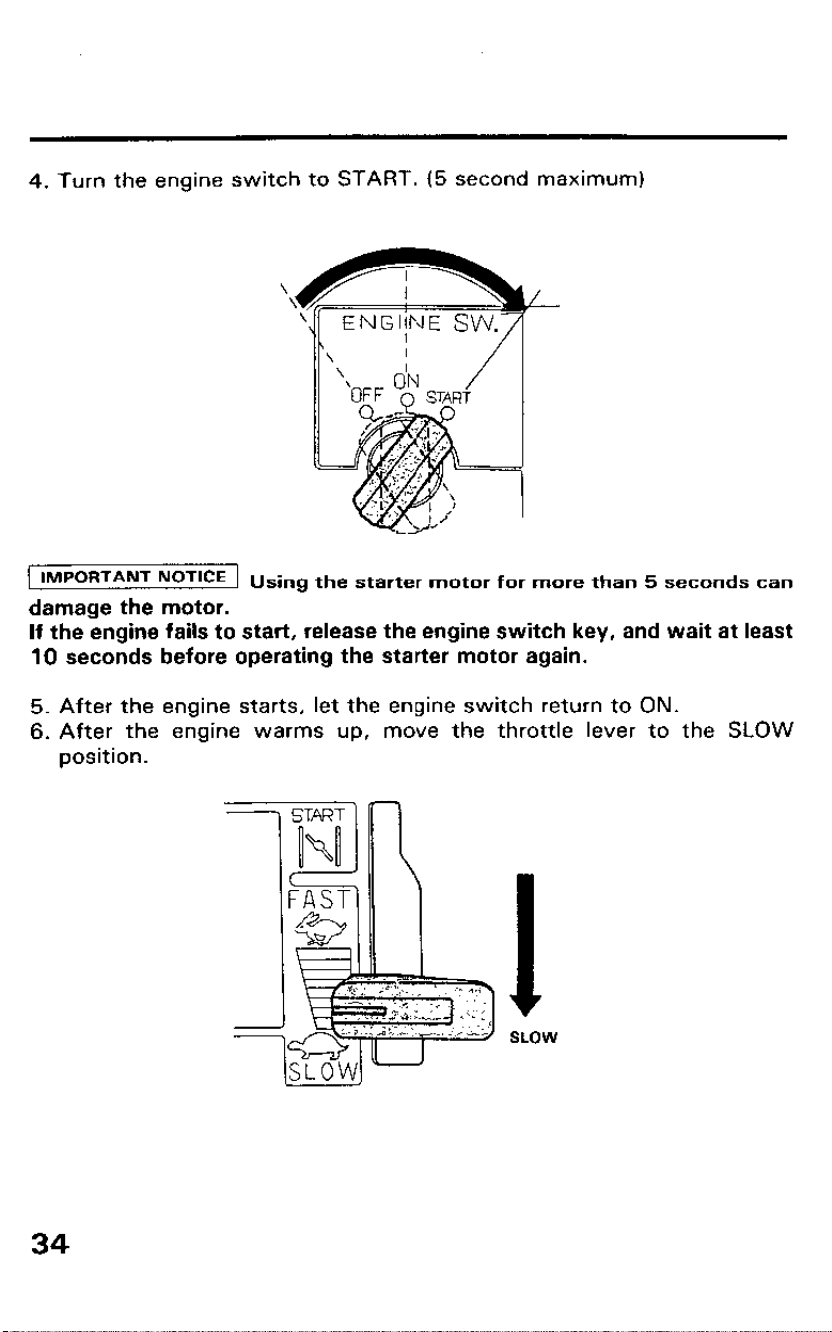
4. Turn the engine switch to START. (5 second maximum)
\
IMPORTANT NoT’CE Using the starter motor for more than 5 seconds can
damage the motor.
If the engine fails to start, release the engine switch key, and wait at least
10 seconds before operating the starter motor again.
5. After the engine starts, let the engine switch return to ON.
6. After the engine warms up, move the throttle lever to the SLOW
position.
34
.
.
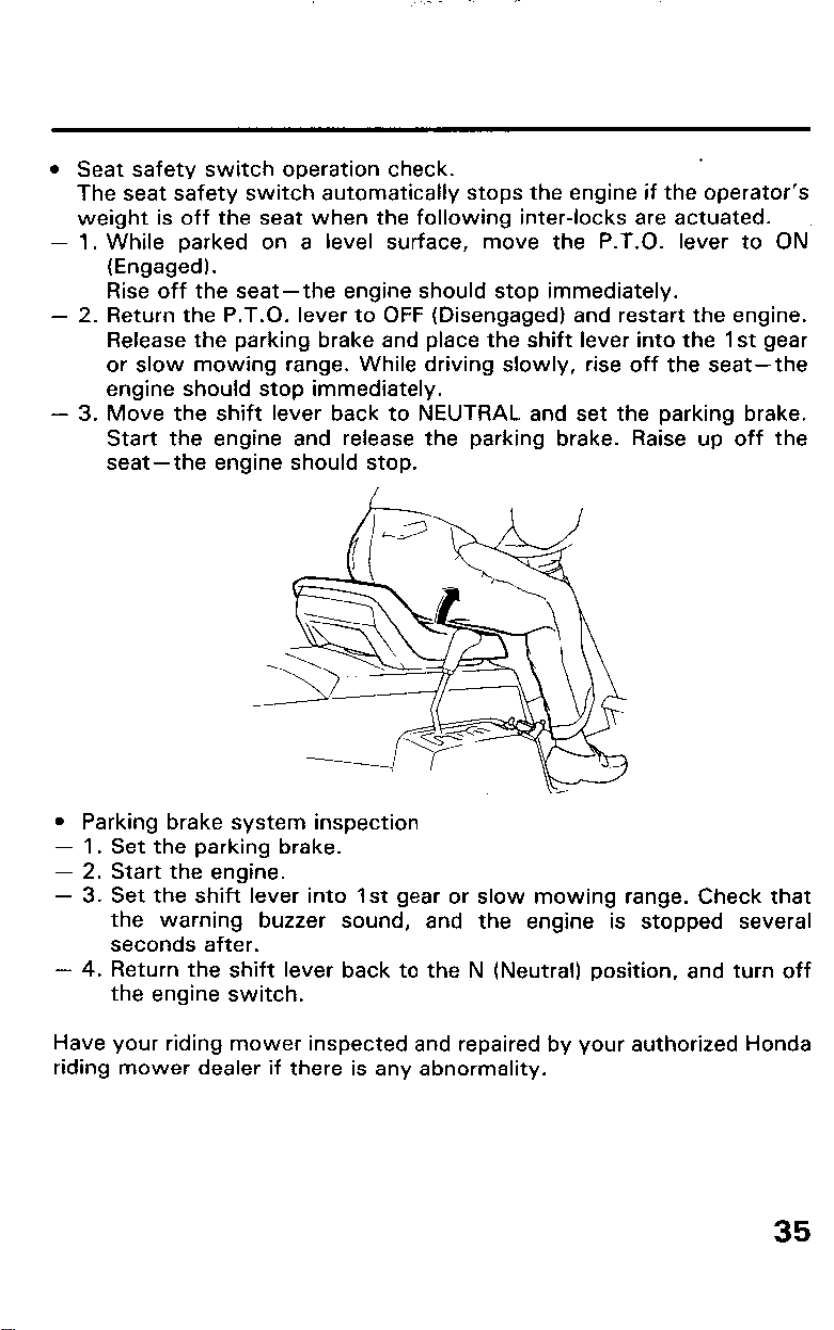
l Seat safety switch operation check.
The seat safety switch automatically stops the engine if the operator’s
weight is off the seat when the following inter-locks are actuated.
-
1. While parked on a level surface, move the P.T.O. lever to ON
(Engaged).
Rise off the seat-the engine should stop immediately.
- 2. Return the P.T.O. lever to OFF (Disengaged) and restart the engine.
Release the parking brake and place the shift lever into the 1st gear
or slow mowing range. While driving slowly, rise off the seat-the
engine should stop immediately.
- 3. Move the shift lever back to NEUTRAL and set the parking brake.
Start the engine and release the parking brake. Raise up off the
seat-the engine should stop.
l Parking brake system inspection
- 1. Set the parking brake.
- 2. Start the engine.
- 3. Set the shift lever into 1st gear or slow mowing range. Check that
the warning buzzer sound, and the engine is stopped several
seconds after.
- 4. Return the shift lever back to the N (Neutral) position, and turn off
the engine switch.
Have your riding mower inspected and repaired by your authorized Honda
riding mower dealer if there is any abnormality.
35
Mowing
m
Before operating this riding mower you should read and under-
stand the SAFETY INSTRUCTION on pages 4-7.
1 IMPORTANT NOTICE 1
l Be aware of rocks, roots, holes and hidden hazards in the terrain. Un-
seen hazards may cause loss of control or damage the riding mower.
l In tall grass, first mow with the cutter deck fully raised (3 l/2”); this will
help expose any hidden obstacles. When you are sure the area is com-
pletely cleared, re-mow at the desired height.
l If the riding mower should accidentally gets caught by an unseen ob-
ject, (holes, roots, or rocks) do not try to ride over the obstruction or
turn the steering wheel to free the mower. This will damage the steer-
ing mechanism or cutter deck.
l Operating the riding mower near the edge of a ditch or an embankment
could cause the mower to tip or roll-over.
l Avoid sharp turns or sudden stops on sloping surfaces. Avqid backing
down or rapid acceleration on sloping surfaces. Both of which could
cause loss of control.
l Stop the engine before removing the grass bags or cleaning the
discharge chute.
l Empty the grass bags after use to avoid creating a fire hazard when the
riding mower is stored.
Mowing tips
l For good mowing conditions, the grass should not be wet, but the
ground should be damp to control dust.
l If dust is a problem, water the lawn the day before mowing, allowing
the grass to dry while the ground remains moist.
l Always allow the grass to dry before cutting. Cutting wet grass will
cause the cutter deck or the discharge to clog, resulting in poor cut
quality.
36
.
.
.
.
.
.
.
.
.
.
Always engage the P.T.O. before selecting the desired mowing speed
to avoid leaving uncut grass. Engaging the P.T.O. in tall uncut grass
may cause the e.ngine to stall.
Mow at full throttle with the transmission in the desired mowing speed
for the best cut quality and performance. Mowing in a medium or low
throttle setting will affect the performance and cut quality.
After selecting the desired mowing speed, you should remain in that
range when mowing for the best results. Avoid making rapid mowing
speed changes from slow to fast when mowing, this will affect cut
quality.
Avoid shifting to the transport range when mowing. Mowing in the
transport range is not recommended, as this will affect cut quality.
Transport range should only be used to drive to and from the mowing
area.
If the lawn is thick, lush, or uneven, lower the mowing speed, raise the
cutter deck and cut a narrower swath.
If the lawn has grown too tall, lower the mowing speed, raise the cutter
deck height and mow twice (first at a high cutter deck setting, then at
the desired height).
For a finish trim cut, lower the mowing speed and mow the lawn
counterclockwise around trees, post, flower beds, sprinklers and other
obstacles.
An adjustment of the cutter deck may be required if the grass does not
cut properly. Have the cutter deck height inspected and adjusted by an
authorized Honda riding mower dealer. First, verify the deck is clean
and the blades are in good condition.
If mowing on a sloping surface, always drive up and down the face of
the grade. Never turn around or drive across the face of the slope; this
may cause the mower to tip over.
To prevent tipping or loss of control, always reduce the ground speed
and exercise extreme caution when operating on slopes and uneven
surfaces.
37
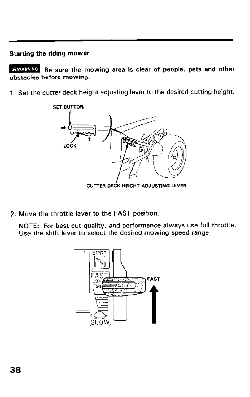
Starting the riding mower
m
Be sure the mowing area is clear of people, pets and other
obstacles before mowing.
1. Set the cutter deck height adjusting lever to the desired cutting height.
SET BUTTON
CUTTER DEdK
HEIGHT ADJUSTING LEVER
2.
Move the throttle lever to the FAST position.
NOTE: For best cut quality, and performance always use full throttle.
Use the shift lever to select the desired mowing speed range.
FAST
1
38
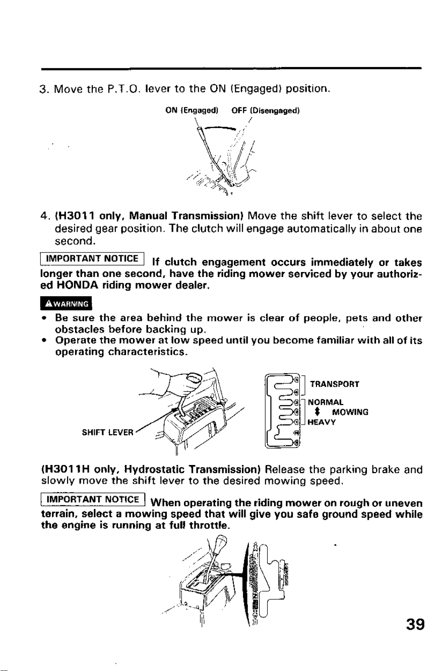
3. Move the P.T.O. lever to the ON (Engaged) position.
ON (Engaged)
OFF (Disengaged)
\
/
4. (H3011 only, Manual Transmission) Move the shift lever to select the
desired gear position. The clutch will engage automatically in about one
second.
IMPORTANT NoT’CE If clutch engagement occurs immediately or takes
longer than one second, have the riding mower serviced by your authoriz-
ed HONDA riding mower dealer.
m
l Be sure the area behind the mower is clear of people, pets and other
obstacles before backing up.
l Operate the mower at low speed until you become familiar with all of its
operating characteristics.
SHIFT LEVER
(H301 IH only, Hydrostatic Transmission) Release the parking brake and
slowly move the shift lever to the desired mowing speed.
IMPORTANT NoT’CE When operating the riding mower on rough or uneven
terrain, select a mowing speed that will give you safe ground speed while
the engine is running at full throttle.
39
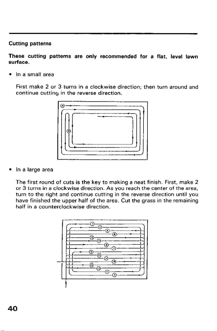
Cutting patterns
These cutting patterns are only recommended for a flat, level lawn
surface.
l In a small area
First make 2 or 3 turns in a clockwise direction; then turn around and
continue cutting in the reverse direction.
l In a large area
The first round of cuts is the key to making a neat finish. First, make 2
or 3 turns in a clockwise direction. As you reach the center of the area,
turn to the right and continue cutting in the reverse direction until you
have finished the upper half of the area. Cut the grass in the remaining
half in a counterclockwise direction.
40
Mowing on unsquare areas
If your mowing area is not square or four-sided, divide the area into
several blocks so you can mow in a neat mowing pattern.
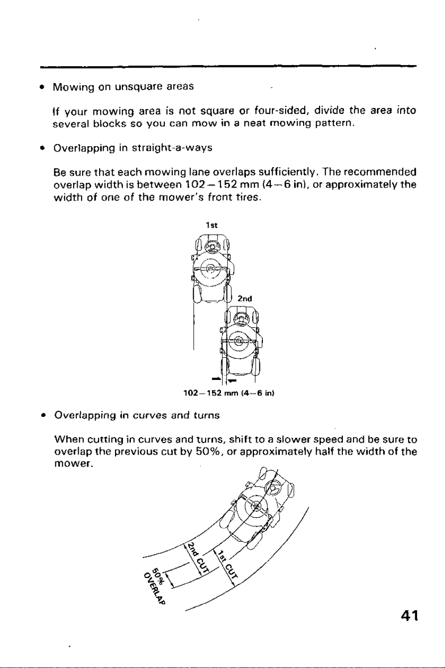
Overlapping in straight-a-ways
Be sure that each mowing lane overlaps sufficiently. The recommended
overlap width is between 102- 152 mm (4-6 in), or approximately the
width of one of the mower’s front tires.
1st
102-152 mm (4-6 in)
Overlapping in curves and turns
When cutting in curves and turns, shift to a slower speed and be sure to
overlap the previous cut by 50%, or approximately half the width of the
mower.
41
Uphill starting procedure (H3011 only, Manual Transmission)
If possible, avoid stopping the riding mower while driving uphill. However,
if it is necessary to stop, follow this special procedure:
1. Set parking brake.
2. Apply pressure to the brake pedal.
3. Move the throttle lever to mid range.
4. Shift the transmission to 1st gear position.
5. Release the brake pedal.
6. Wait until the clutch engages.
(The warning buzzer will sound until the parking brake is released. If the
parking brake is not released, the engine will automatically stop within a
few seconds.)
7. Then release the parking brake lever.
If the parking brake lever is released before the brake pedal, the riding
mower may roll downhill before the clutch engages. This may cause the
riding mower to tip over.
[H3011 H only, Hydrostatic Transmission]
Stopping on a hill
If possible avoid stopping the riding mower while driving uphill.
If it is necessary to stop on a hill, follow the procedures below.
1. Depress the foot the brake to the floor (shift lever returns to “N”).
2. Move the P.T.O. lever to the OFF (disengaged) position.
3. Set the parking brake.
Uphill starting procedure
It is important to follow the uphill starting carefully to avoid tipping the
riding mower over.
1. Release the parking brake.
2. Slowly move the shift lever to the desired speed range.
m
Moving the shift lever too quickly while starting uphill may
cause the mower to tip over. Always move the shift lever slowly and
gradually.
42
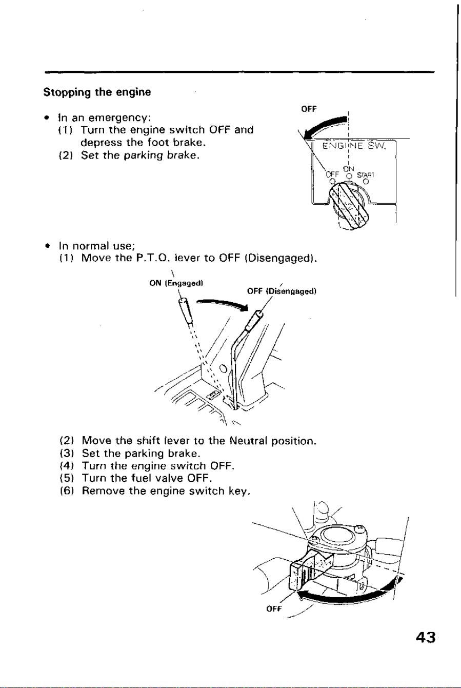
Stopping the engine
l In an emergency:
(1) Turn the engine switch OFF and
depress the foot brake.
(2) Set the parking brake.
OFF
l In normal use;
(I) Move the P.T.O. lever to OFF (Disengaged).
\
ON (Engaged)
OFF lDis/engaged)
(2) Move the shift lever to the Neutral position.
(3) Set the parking brake.
(4) Turn the engine switch OFF.
(5) Turn the fuel valve OFF.
(6) Remove the engine switch key.
High Altitude Operation
At high altitude, the standard carburetor air-fuel mixture will be too rich.
Performance will decrease, and fuel consumption will increase. A very rich
fuel mixture may also foul the spark plugs and cause hard starting.
High altitude performance can be improved by installing a smaller diameter
main fuel jet in the carburetor and readjusting the pilot screw. If you
always operate the engine at altitudes higher than 6,000 feet above sea
level, have an authorized Honda riding mower dealer perform this carbu-
retor modification.
Even with carburetor modification, engine horsepower w :II decrease about
3.5% for each 1,000 feet increase in altitude. The effect of altitude on
horsepower will be greater than this if no carburetor modification is made.
Whe,n the carburetor is modified for good high altitude operation, the
air/fuel mixture will be too lean at low altitude. Performance will decrease,
the engine will overheat.
To avoid an excessively lean air/fuel mixture, reinstall the standard main
jet and readjust the pilot screw for operation at altitudes lower than 6,000
feet above sea level.
44
6. TRANSPORTING
Transporting
The engine becomes very hot during operation and remains hot for a while
after stopping. Allow the engine to cool before transporting.
m
Contact with a hot engine or exhaust system can cause serious
burns or fires. Let the engine cool before transporting.
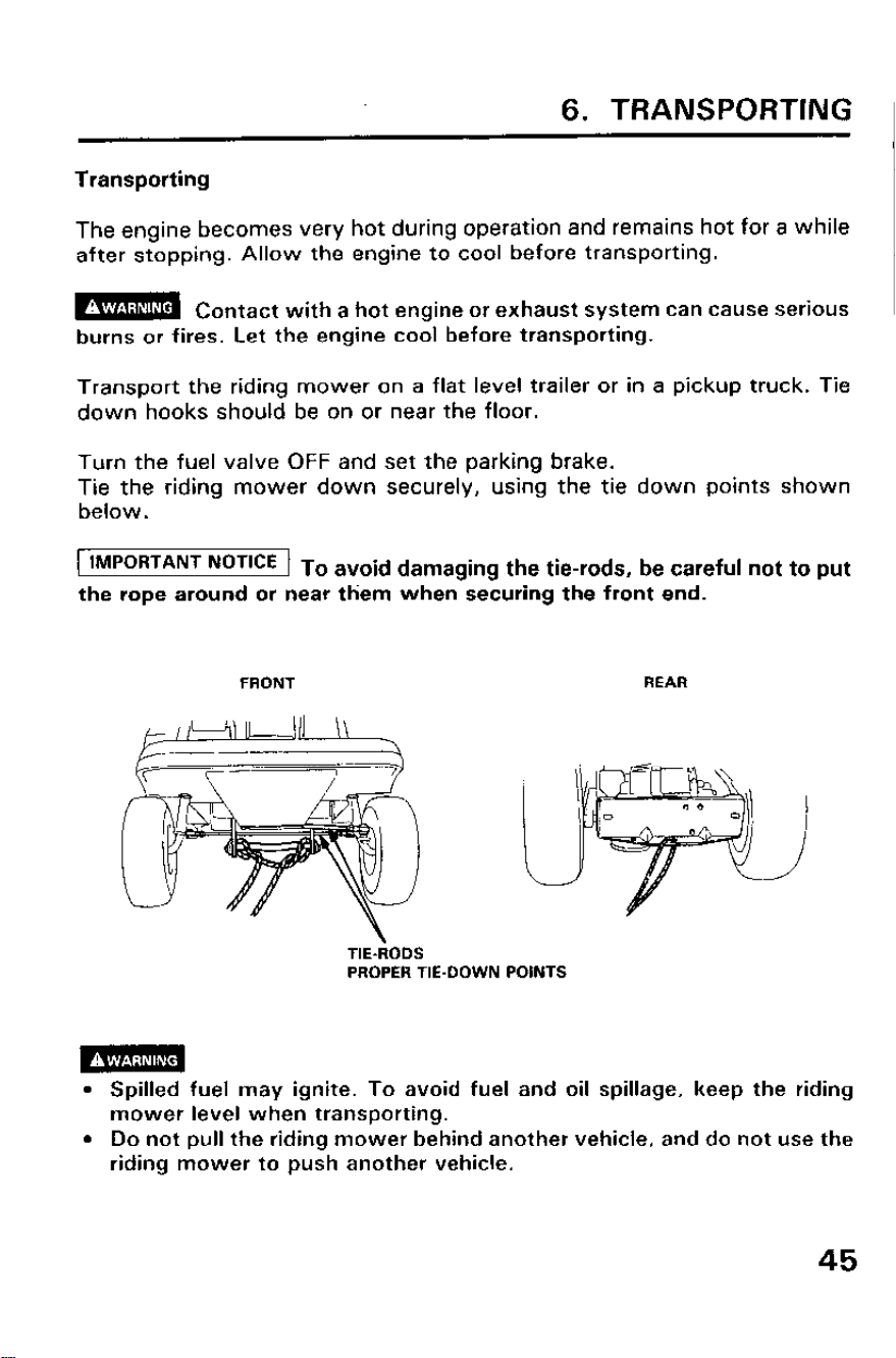
Transport the riding mower on a flat level trailer or in a pickup truck. Tie
down hooks should be on or near the floor.
Turn the fuel valve OFF and set the parking brake.
Tie the riding mower down securely, using the tie down points shown
below.
IMPORTANT NoT’CE To avoid damaging the tie-rods, be careful not to put
the rope around or near them when securing the front end.
FRONT
REAR
TIE-RODS
PROPER TIE-DOWN POINTS
l Spilled fuel may ignite. To avoid fuel and oil spillage, keep the riding
mower level when transporting.
l Do not pull the riding mower behind another vehicle, and do not use the
riding mower to push another vehicle.
45
7. MAINTENANCE
Periodic maintenance and adjustment are necessary to keep the riding
mower in good operating condition. Service and inspect according to the
MAINTENANCE SCHEDULE.
l To avoid carbon monoxide poisoning, shut off the engine before
performing any maintenance. If you run the engine in an area that is
confined, or even partially enclosed, the air you breathe will contain a
dangerous amount of exhaust gas. If the engine must be run for any
reason, be sure the area is well-ventilated.
l To avoid serious burns, allow the engine to cool before performing
maintenance.
l Shut the engine off and set the parking brake before performing any
maintenance.
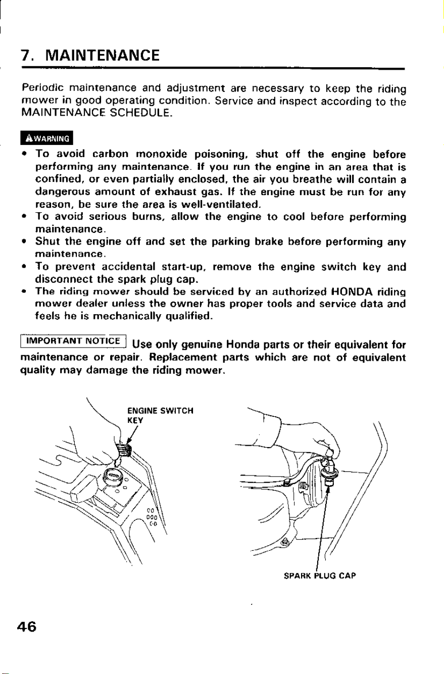
l To prevent accidental start-up, remove the engine switch key and
disconnect the spark plug cap.
l The riding mower should be serviced by an authorized HONDA riding
mower dealer unless the owner has proper tools and service data and
feels he is mechanically qualified.
IMPORTANT NOTICE
1 Use only genuine Honda parts or their equivalent for
maintenance or repair. Repla&ment parts which are not of equivalent
quality may damage the riding mower.
SPARK iLUG CAP
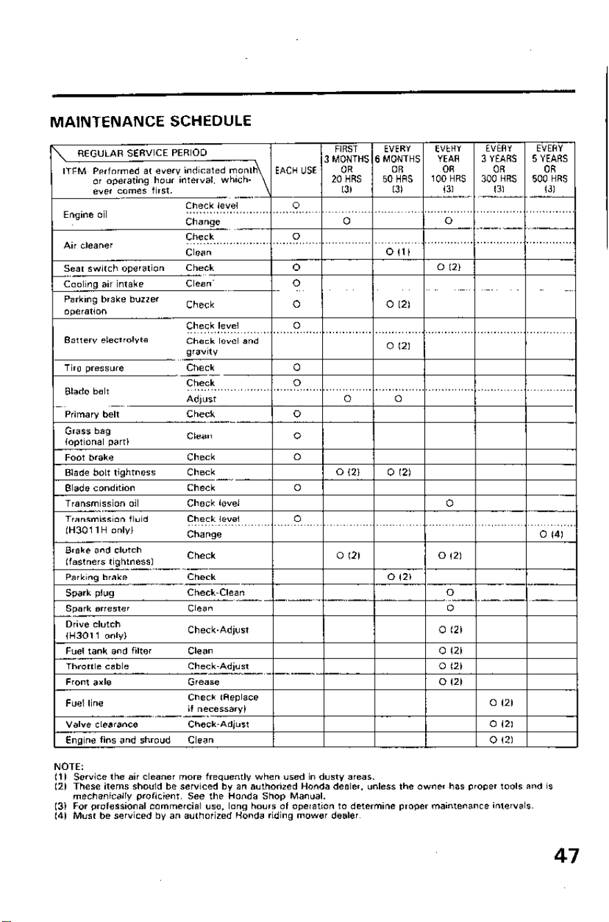
MAINTENANCE SCHEDULE
Engine 01
NOTE:
I1 I Service the air cleaner more frequently when used in dusty areas.
(2) These items should be serviced by an authorized Honda dealer. unless the owner has proper tools and is
mechanically proficient. See the Honda Shop Manual.
13) For professional commercial use. long hours of operation to determine proper maintenance intervals
(4) Must be serviced by an authorized Honda riding mower dealer.
47
Engine Oil Change
Drain the oil while the engine is warm to assure rapid and complete
draining.
NOTE: Used motor oil may cause skin oanoer if repeatedly left in contact
with the skin for prolonged periods.
Although this is unlikely, unless you handle used oil on a daily basis, it is
still advisable to thoroughly wash your hands with soap and water as soon
as possible after handling used oil.
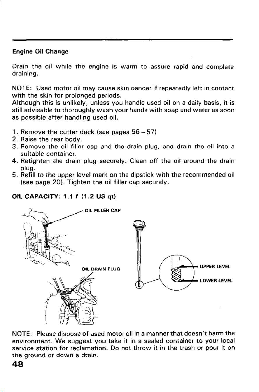
1. Remove the cutter deck (see pages 56-57)
2. Raise the rear body.
3. Remove the oil filler cap and the drain plug, and drain the oil into a
suitable container.
4. Retighten the drain plug securely. Clean off the oil around the drain
Ph.
5. Refill to the upper level mark on the dipstick with the recommended oil
(see page 20). Tighten the oil filler cap securely.
OIL CAPACITY: 1 .I P (1.2 US qt)
OIL FILLER CAP
OIL DRAIN PLUG
UPPER LEVEL
LOWER LEVEL
NOTE: Please dispose of used motor oil in a manner that doesn’t harm the
environment. We suggest you take it in a sealed container to your local
service station for reclamation. Do not throw it in the trash or pour it on
the ground or down a drain.
48
Air Cleaner Service
A dirty air cleaner will restriot air flow to the carburetor. If you operate the
riding mower in very dusty areas, clean the air cleaner more often than
specified in the MAINTENANCE SCHEDULE.
Operating the engine without the air cleaner will cause rapid engine wear.
1. Raise the rear body.
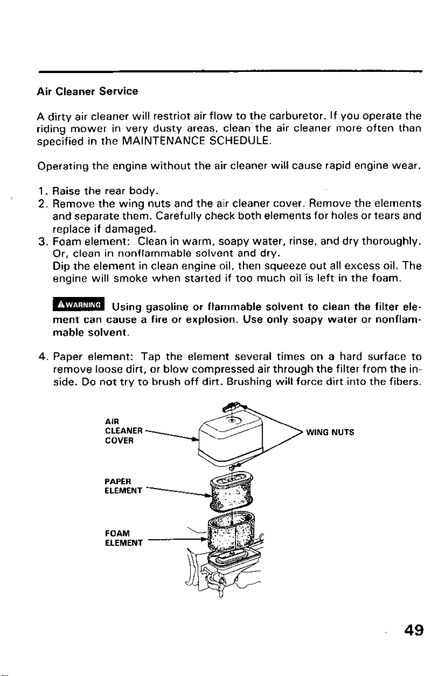
2. Remove the wing nuts and the air cleaner cover. Remove the elements
and separate them. Carefully check both elements for holes or tears and
replace if damaged.
3. Foam element: Clean in warm, soapy water, rinse, and dry thoroughly.
Or, clean in nonflammable solvent and dry.
Dip the element in clean engine oil, then squeeze out all excess oil. The
engine will smoke when started if too much oil is left in the foam.
m.
Usmg gasoline or flammable solvent to clean the filter ele-
ment can cause a fire or explosion. Use only soapy water or nonflam-
mable solvent.
4. Paper element: Tap the element several times on a hard surface to
remove loose dirt, or blow compressed air through the filter from the in-
side. Do not try to brush off dirt. Brushing will force dirt into the fibers.
PAPER
ELEMENT
FOAM
ELEMENT
49
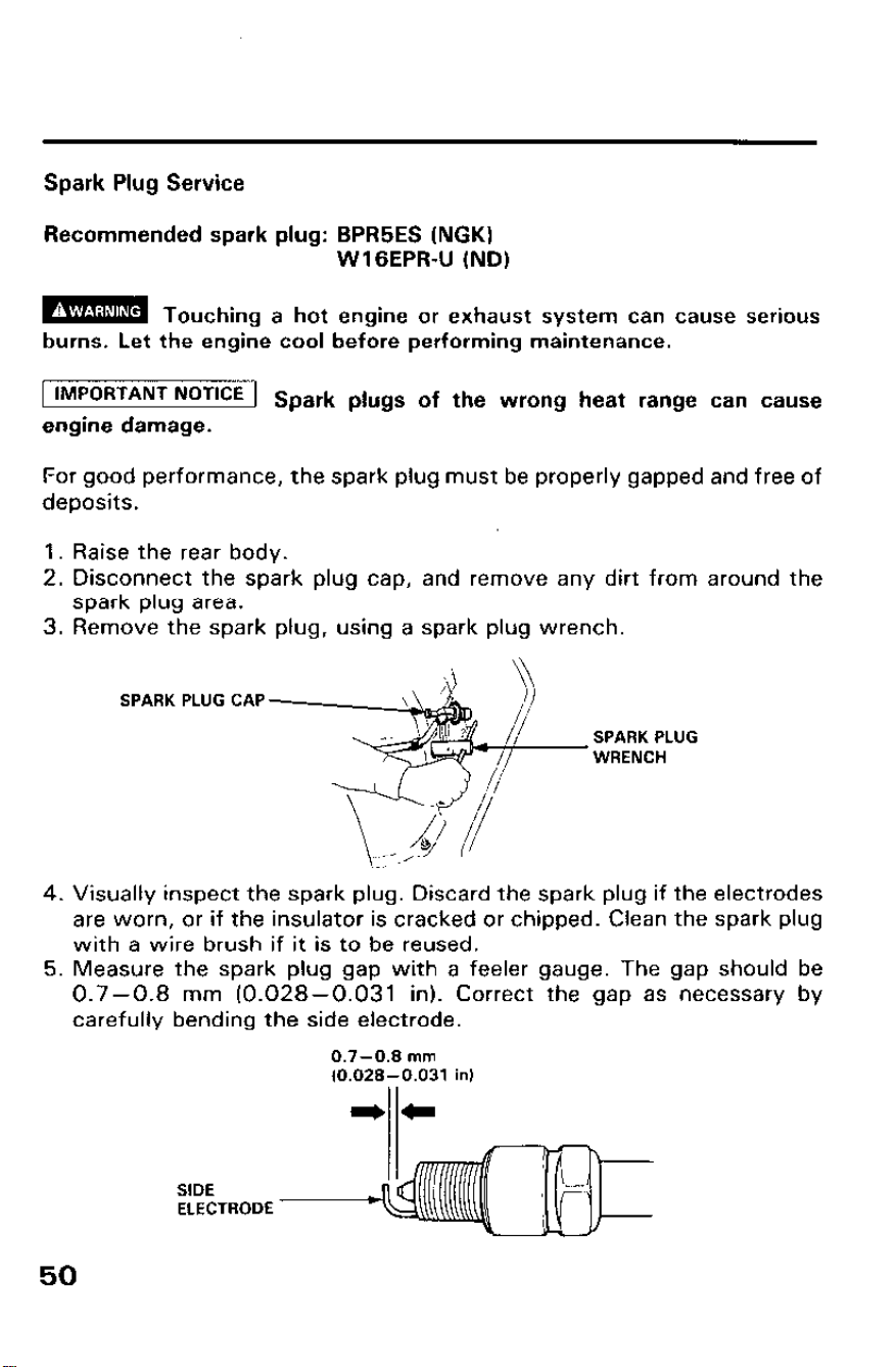
Spark Plug Service
Recommended spark plug: BPR5ES (NGK)
WI GEPR-U (ND)
m
Touching a hot engine or exhaust system can cause serious
burns. Let the engine cool before performing maintenance.
IMPORTANT NOTICE
1 Spark plugs of the wrong heat range can cause
engine damage.
For good performance, the spark plug must be properly gapped and free of
deposits.
1. Raise the rear body.
2. Disconnect the spark plug cap, and remove any dirt from around the
spark plug area.
3. Remove the spark plug, using a spark plug wrench.
SPARK PLUG CAP
SPARK PLUG
WRENCH
4. Visually inspect the spark plug. Discard the spark plug if the electrodes
are worn, or if the insulator is cracked or chipped. Clean the spark plug
with a wire brush if it is to be reused.
5. Measure the spark plug gap with a feeler gauge. The gap should be
0.7-0.8 mm (0.028-0.031 in). Correct the gap as necessary by
carefully bending the side electrode.
0.7-0.8 mm
fO.O28-0.031 in)
SIDE
ELECTRODE
50
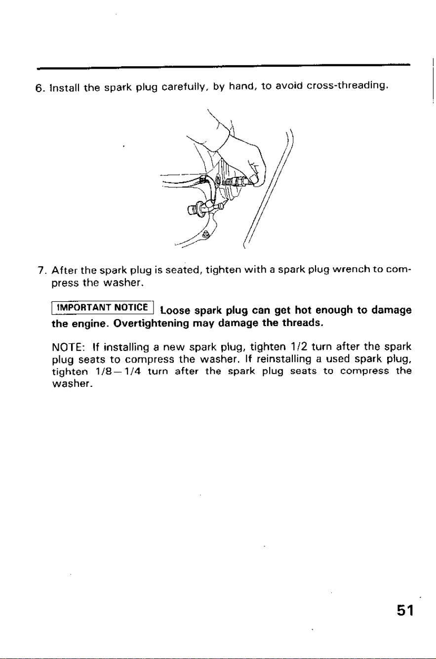
6. Install the spark plug carefully, by hand, to avoid cross-threading.
7. After the spark plug is seated, tighten with a spark plug wrench to com-
press the washer.
IMPORTANT NoT’CE
Loose spark plug can get hot enough to damage
the engine. Overtightening may damage the threads.
NOTE: If installing a new spark plug, tighten l/2 turn after the spark
plug seats to compress the washer. If reinstalling a used spark plug,
tighten l/8- l/4 turn after the spark plug seats to compress the
washer.
51

Battery Service
H Refilling battery fluid
If the riding mower is operated with insufficient battery electrolyte, sulfa-
tion and battery plate damage will occur.
If rapid loss of electrolyte is experienced, or if your battery seems to be
weak, causing slow starting or other electrical problems, see your
authorized Honda riding mower dealer.
Raise the rear body and check the electrolyte level in each battery cell. Fill
the battery with distilled water to the upper level line. Never overfill the
battery.
m
Batteries produce explosive gases: If ignited, an explosion can
cause serious injury or blindness.
Provide adequate Jentilation when
charging.
l CHEMICAL HAZARD: Battery electrolyte contains sulfuric acid. Con-
tact with eyes or skin, even through plathins, may cause severe burns.
Wear a faceshield and protective clothing.
l Keep flames and sparks away, and do not smoke in the area.
ANTIDOTE: If electrolyte gets into your eyes, flush tlroroughly with
warm water for at least 15 minutes and call a physician immediately.
l POISON: Electrolyte is poison.
ANTIDOTE
-
External: Flush thoroughly with water.
-
Internal: Drink large quantities of water or milk.
Follow with milk of magnesia or vegetable oil, and call a physician
immediately.
. KEEP OUT OF REACH OF CHILDREN.
NOTE: Use distilled water in the battery.
l Tap water will shorten the service life of the battery.
l Overfilling may cause electrolyte overflow and corrosion. Wash off any
spilled electrolyte immediately.
UPPER LEVEL
LOWER LEVEL
52
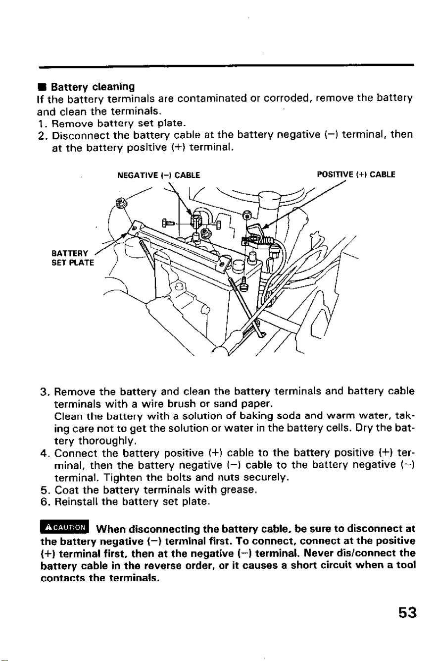
H Battery cleaning
If the battery terminals are contaminated or corroded, remove the battery
and clean the terminals.
1. Remove battery set plate.
2. Disconnect the battery cable at the battery negative (-1 terminal, then
at the battery positive (+I terminal.
NEGATIVE (-1 CABLE
POSITIVE (+) CABLE
BATTERY
SET PLATE
3. Remove the battery and clean the battery terminals and battery cable
terminals with a wire brush or sand paper.
Clean the battery with a solution of baking soda and warm water, tak-
ing care not to get the solution or water in the battery cells. Dry the bat-
tery thoroughly.
4. Connect the battery positive (+I cable to the battery positive (+I ter-
minal, then the battery negative (-1 cable to the battery negative (-1
terminal. Tighten the bolts and nuts securely.
5. Coat the battery terminals with grease.
6. Reinstall the battery set plate.
m
When disconnecting the battery cable, be sure to disconnect at
the battery negative (-1 terminal first. To connect, connect at the positive
(+I terminal first, then at the negative (-1 terminal. Never dis/connect the
battery cable in the reverse order, or it causes a short circuit when a tool
contacts the terminals.
53
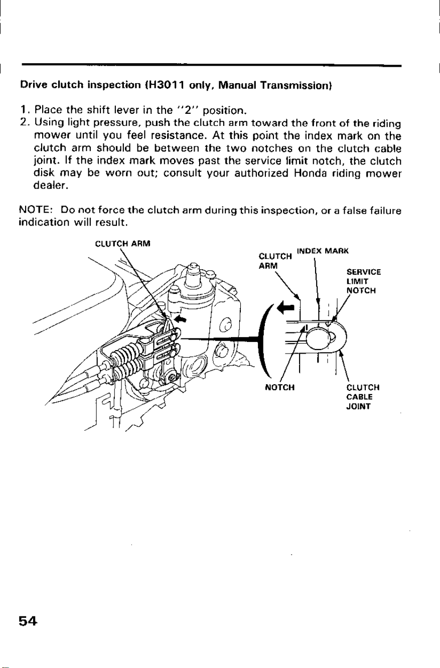
Drive clutch inspection (H3011 only, Manual Transmission)
1. Place the shift lever in the “2” position.
2. Using light pressure, push the clutch arm toward the front of the riding
mower until you feel resistance. At this point the index mark on the
clutch arm should be between the two notches on the clutch cable
joint. If the index mark moves past the service limit notch, the clutch
disk may be worn out; consult your authorized Honda riding mower
dealer.
NOTE: Do not force the clutch arm during this inspection, or a false failure
indication will result.
CLUTCH INDEX MARK
SERVICE
‘- ^““\ 1 NOTCH
LIMIT
CLUTCH ARM
NOTCH
CLUTCH
CABLE
JOINT
54
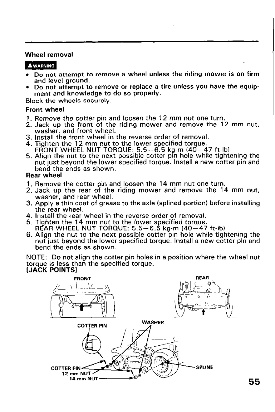
Wheel removal
l Do not attempt to remove a wheel unless the riding mower is on firm
and level ground.
l Do not attempt to remove or replace a tire unless you have the equip-
ment and knowledge to do so properly.
Block the wheels securely.
Front wheel
1. Remove the cotter pin and loosen the 12 mm nut one turn.
2. Jack up the front of the riding mower and remove the 12 mm nut,
washer, and front wheel.
3. Install the front wheel in the reverse order of removal.
4. Tighten the 12 mm nut to the lower specified torque.
FRONT WHEEL NUT TORQUE: 5.5-6.5 kg-m (40-47 ft-lb)
5. Align the nut to the next possible cotter pin hole while tightening the
nut just beyond the lower specified torque. Install a new cotter pin and
bend the ends as shown.
Rear wheel
1. Remove the cotter pin and loosen the 14 mm nut one turn.
2. Jack up the rear of the riding mower and remove the 14 mm nut,
washer, and rear wheel.
3. Apply a thin coat of grease to the axle (splined portion) before installing
the rear wheel.
4. Install the rear wheel in the reverse order of removal.
5. Ti hten the 14 mm nut to the lower specified torque.
Rl!AR WHEEL NUT TORQUE: 5.5-6.5 kg-m (40-47 ft-lb)
6. Align the nut to the next possible cotter pin hole while tightening the
nut just beyond the lower specified torque. Install a new cotter pin and
bend the ends as shown.
NOTE: Do not align the cotter pin holes in a position where the wheel nut
torque is less than the specified torque.
[JACK POINTS]
FRONT
REAR
WASHER
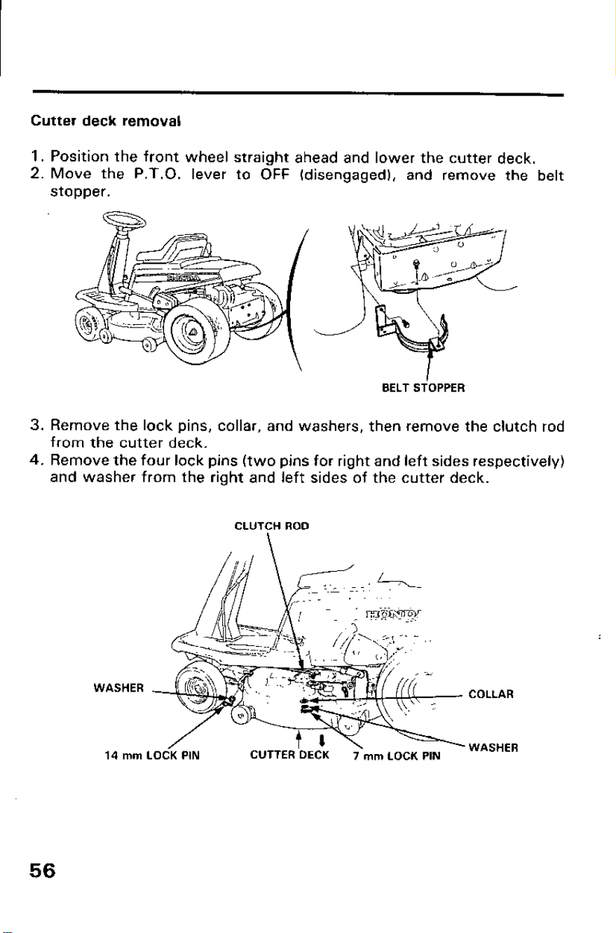
Cutter deck removal
1. Position the front wheel straight ahead and lower the cutter deck.
2. Move the P.T.O. lever to OFF (disengaged), and remove the belt
stopper.
BELT STOPPER
3. Remove the lock pins, collar, and washers, then remove the clutch rod
from the cutter deck.
4. Remove the four lock pins (two pins for right and left sides respectively)
and washer from the right and left sides of the cutter deck.
CLUTCH ROD
WASHER
14 mm
COLLAR
LOCK PIN
CUTTER DECK
7 mm LOCK PIN
WASHER
56
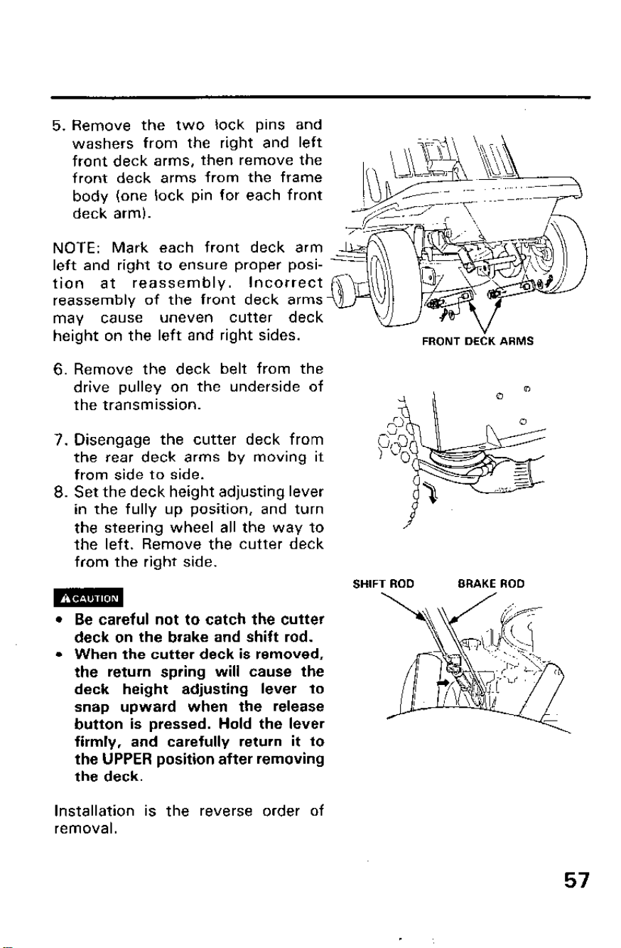
NOTE: Mark each front deck arm
left and right to ensure proper posi-
tion at reassembly. Incorrect
reassemblv of the front deck arms
may cause uneven cutter deck
height on the left and right sides.
6. Remove the deck belt from the
drive pulley on the underside of
the transmission.
7. Disengage the cutter deck from
the rear deck arms by moving it
from side to side.
8. Set the deck height adjusting lever
in the fully up position, and turn
the steering wheel all the way to
the left. Remove the cutter deck
from the right side.
5. Remove the two lock pins and
washers from the right and left
front deck arms, then remove the
front deck arms from the frame
body (one lock pin for each front
deck arm).
FRONT DECK ARMS
l Be careful not to catch the cutter
deck on the brake and shift rod.
l When the cutter deck is removed,
the return spring will cause the
deck height adjusting lever to
snap upward when the release
button is pressed. Hold the lever
firmly, and carefully return it to
the UPPER position after removing
the deck.
Installation is the reverse order of
removal.
SHIFT ROD BRAKE ROD
57
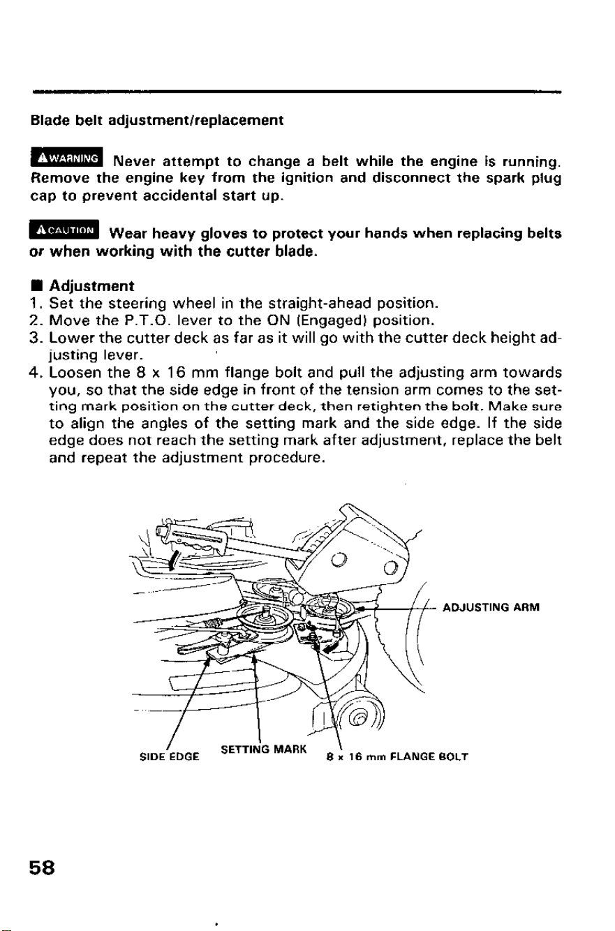
Blade belt adjustment/replacement
m
Never attempt to change a belt while the engine is running.
Remove the engine key from the ignition and disconnect the spark plug
cap to prevent accidental start up.
m Wear heavy gloves to protect your hands when replacing belts
or when working with the cutter blade.
n Adjustment
1. Set the steering wheel in the straight-ahead position.
2. Move the P.T.O. lever to the ON (Engaged) position.
3. Lower the cutter deck as far as it will go with the cutter deck height ad-
justing lever.
4. Loosen the 8 x 16 mm flange bolt and pull the adjusting arm towards
you, so that the side edge in front of the tension arm comes to the set-
ting mark position on the cutter deck, then retighten the bolt. Make sure
to align the angles of the setting mark and the side edge. If the side
edge does not reach the setting mark after adjustment, replace the belt
and repeat the adjustment procedure.
ADJUSTING
SIDE:DGE
SETTIN’G MARK
’
8 x 18 mm FLANGE
58
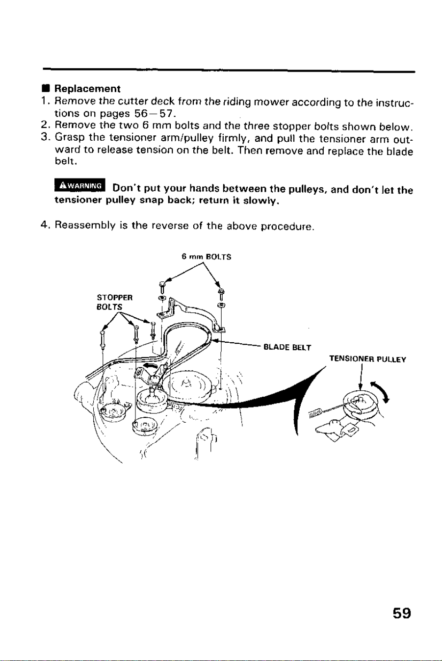
n Replacement
1. Remove the cutter deck from the riding mower according to the instruc-
tions on pages 56-57.
2. Remove the two 6 mm bolts and the three stopper bolts shown below.
3. Grasp the tensioner arm/pulley firmly, and pull the tensioner arm out-
ward to release tension on the belt. Then remove and replace the blade
belt.
m Don’t put your hands between the pulleys, and don’t let the
tensioner pulley snap back; return it slowly.
4. Reassembly is the reverse of the above procedure.
6 mm BOLTS
59
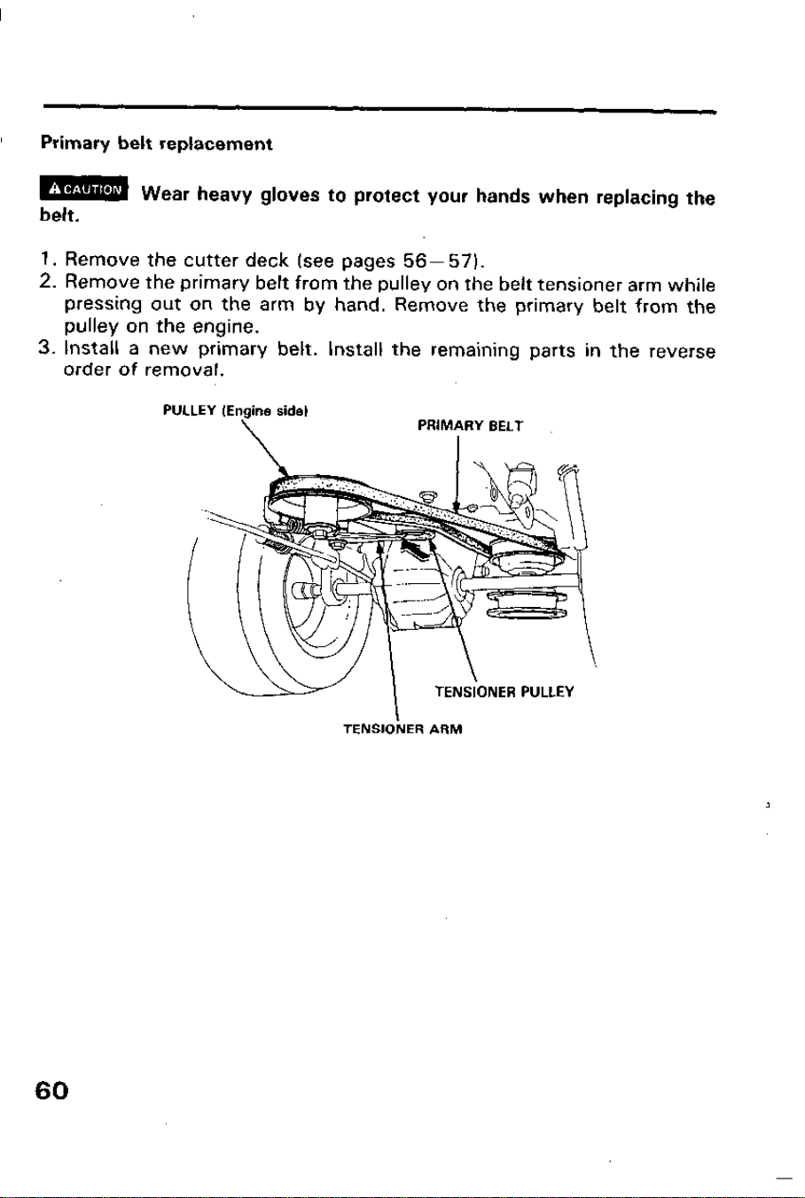
Primary belt replacement
mm
belt.
Wear heavy gloves to protect your hands when replacing the
1. Remove the cutter deck (see pages 56- 57).
2. Remove the primary belt from the pulley on the belt tensioner arm while
pressing out on the arm by hand. Remove the primary belt from the
pulley on the engine.
3. Install a new primary belt. Install the remaining parts in the reverse
order of removal.
PULLEY (Engine side)
\
PRIMARY BELT
I
I
TENSIONER ARM
60

Blade bolt tightness/Blade replacement
m To avoid severe personal injury, remove the ignition key and
disconnect the spark plug cap to prevent accidental starting; wear heavy
gloves to protect your hands from the cutter blade.
n Blade bolt tightness
- 1.
- 2.
- 3.
- 4.
Remove the cutter deck from the riding mower (see page 56).
Turn the cutter deck upside down.
Clean dirt and grass from the blade and the inside of the cutter deck.
Hold the blade firmly, and use a torque wrench to check that the
blade bolt is properly tightened.
12 x 25 mm bolt tightening torque: 8.5 kg-m (61.5 fat-lb)
Blade bolt tightening torque: 5.0 kg-m (36.2 ft-lb1
TORQUE WRENCH
GLOVES
BLADE
H
1.
2.
Blade removal
Hold the blade firmly, and remove the blade bolt, 12 x 25 mm bolts,
blade washer, spring washers and blade.
Remove the blade and blade holder.
12 x 25 mm BOLTS (2)
SPRING WASHERS (2)
BLADE WASHER
BLADE BOLT
BLADE
BLADE HOLDER
61
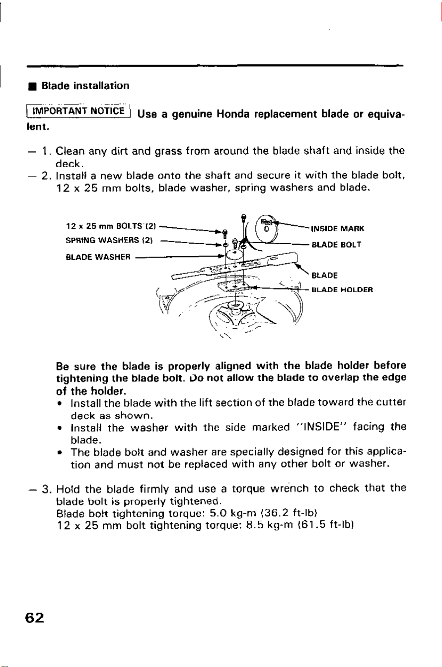
n Blade installation
IMPORTANT NoT1CE Use a genuine Honda replacement blade or equiva-
lent.
-
1. Clean any dirt and grass from around the blade shaft and inside the
deck.
-
2. Install a new blade onto the shaft and secure it with the blade bolt,
12 x 25 mm bolts, blade washer, spring washers and blade.
12 x 25 mm EOLTS’(2)
SPRING WASHERS (2)
BLADE WASHER
INSIDE MARK
BLADE BOLT
BLADE
BLADE HOLDER
Be sure the blade is properly aligned with the blade holder before
tightening the blade bolt. 30 not allow the blade to overlap the edge
of the holder.
l Install the blade with the lift section of the blade toward the cutter
deck as shown.
l Install the washer with the side marked “INSIDE” facing the
blade.
l The blade bolt and washer are specially designed for this applica-
tion and must not be replaced with any other bolt or washer.
-
3. Hold the blade firmly and use a torque wrench to check that the
blade bolt is properly tightened.
Blade bolt tightening torque: 5.0 kg-m (36.2 ft-lb)
12 x 25 mm bolt tightening torque: 8.5 kg-m (61.5 ft-lb)
62
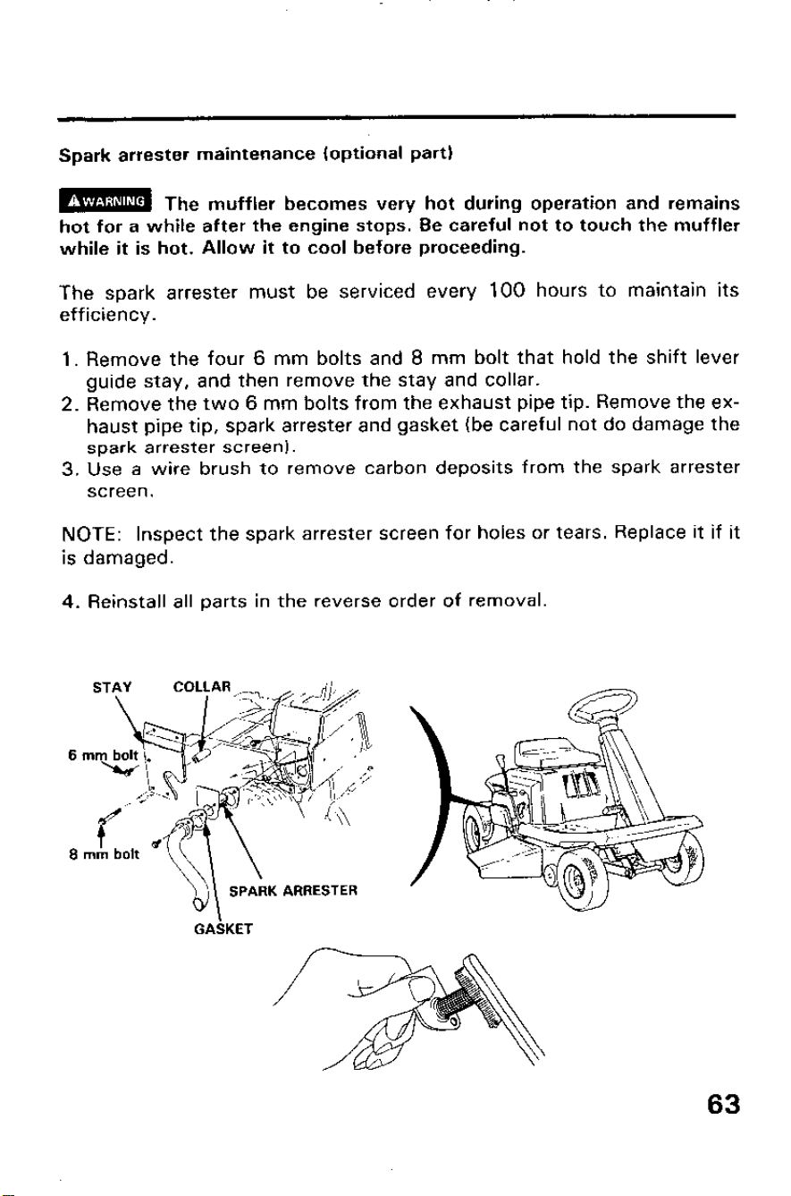
Spark arrester maintenance (optional part)
m The muffler becomes very hot during operation and remains
hot for a while after the engine stops. Be careful not to touch the muffler
while it is hot. Allow it to cool before proceeding.
The spark arrester must be serviced every 100 hours to maintain its
efficiency.
1. Remove the four 6 mm bolts and 8 mm bolt that hold the shift lever
guide stay, and then remove the stay and collar.
2. Remove the two 6 mm bolts from the exhaust pipe tip. Remove the ex-
haust pipe tip, spark arrester and gasket (be careful not do damage the
spark arrester screen).
3. Use a wire brush to remove carbon deposits from the spark arrester
screen.
NOTE:
Inspect the spark arrester screen for holes or tears. Replace it if it
is damaged.
4. Reinstall all parts in the reverse order of removal.
K ARRESTER
GAkKET
63
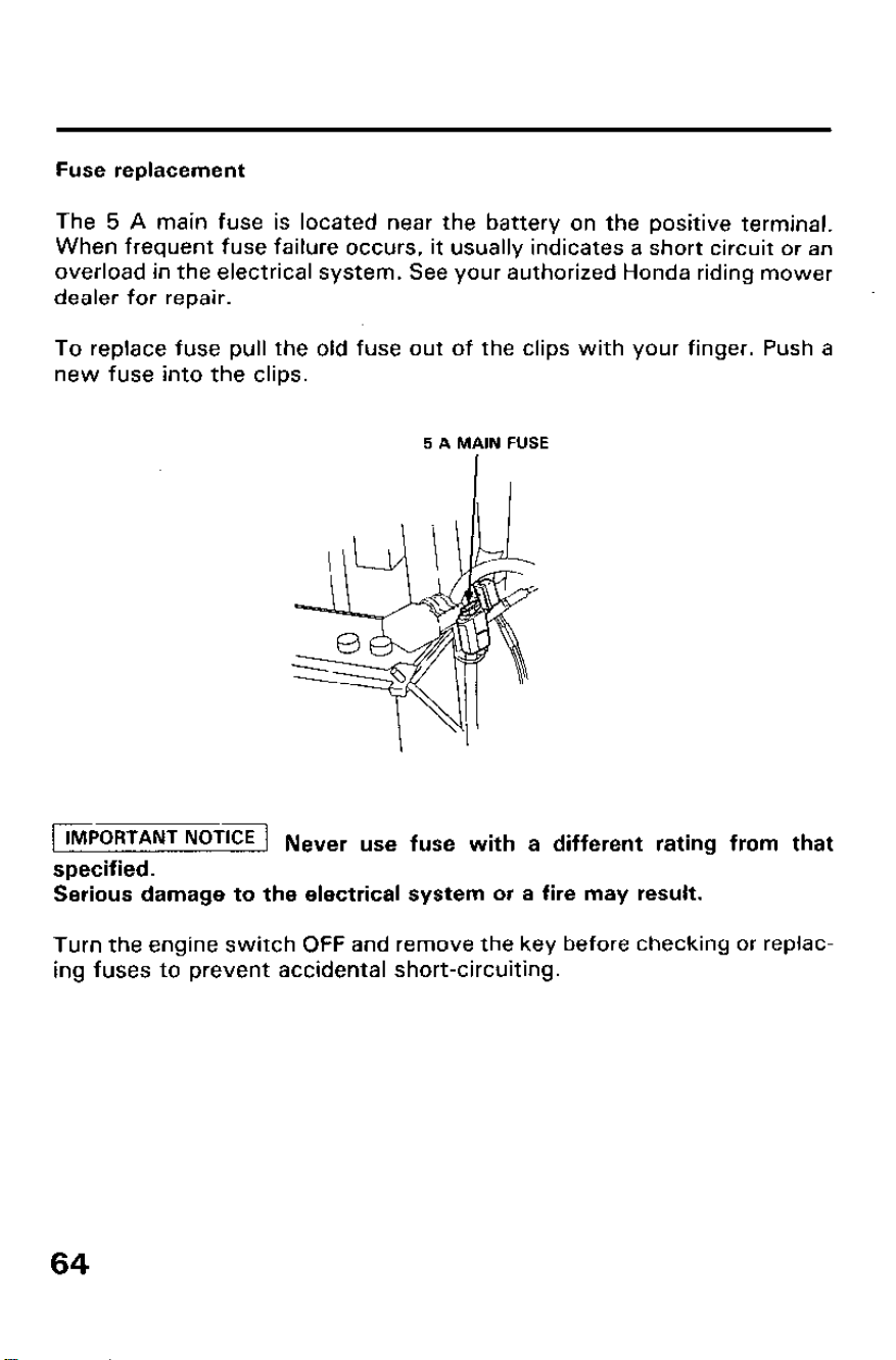
Fuse replacement
The 5 A main fuse is located near the battery on the positive terminal.
When frequent fuse failure occurs, it usually indicates a short circuit or an
overload in the electrical system. See your authorized Honda riding mower
dealer for repair.
To replace fuse pull the old fuse out of the clips with your finger. Push a
new fuse into the clips.
5 A MAIN FUSE
1 IMPORTANT NoTiCE 1 Never use fuse with a different rating from that
specified.
Serious damage to the electrical system or a fire may result.
Turn the engine switch OFF and remove the key before checking or replac-
ing fuses to prevent accidental short-circuiting.
64
8. STORAGE
Preparation for storage
The engine becomes very hot during operation and remains hot for a while
after stopping. Allow the engine to cool before storing.
m
Contact with a hot engine or exhaust system can cause serious
burns or fires. Let the engine cool before storing.
The following steps should be taken to protect the riding mower whenever
it will be stored for longer than 30 days.
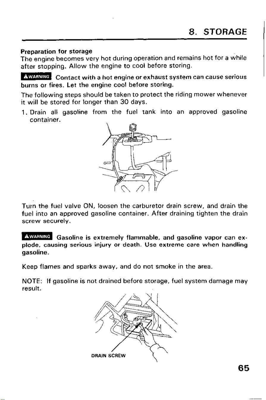
1. Drain all gasoline from the fuel tank into an approved gasoline
container.
Turn the fuel valve ON, loosen the carburetor drain screw, and drain the
fuel into an approved gasoline container. After draining tighten the drain
screw securely.
m
Gasoline is extremely flammable, and gasoline vapor can ex-
plode, causing serious injury or death. Use extreme care when handling
gasoline.
Keep flames and sparks away, and do not smoke in the area.
NOTE: If gasoline is not drained before storage, fuel system damage may
result.
65
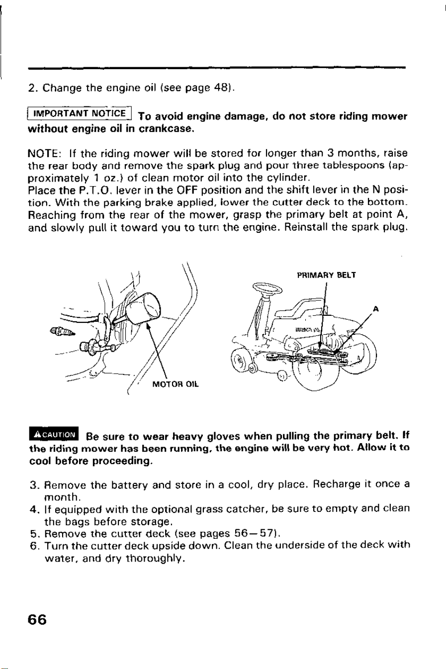
2. Change the engine oil (see page 48).
IMPORTANT NoT’CE To avoid engine damage, do not store riding mower
without engine oil in crankcase.
NOTE: If the riding mower will be stored for longer than 3 months, raise
the rear body and remove the spark plug and pour three tablespoons (ap-
proximately 1 oz.) of clean motor oil into the cylinder.
Place the P.T.O. lever in the OFF position and the shift lever in the N posi-
tion. With the parking brake applied, lower the cutter deck to the bottom.
Reaching from the rear of the mower, grasp the primary belt at point A,
and slowly pull it toward you to turn the engine. Reinstall the spark plug.
\n
PRIMARY BELT
m
Be sure to wear heavy gloves when pulling the primary belt. If
the riding mower has been running, the engine will be very hot. Allow it to
cool before proceeding.
3. Remove the battery and store in a cool, dry place. Recharge it once a
month.
4. If equipped with the optional grass catcher, be sure to empty and clean
the bags before storage.
5. Remove the cutter deck (see pages 56-57).
6. Turn the cutter deck upside down. Clean the underside of the deck with
water, and dry thoroughly.
66
7. For longer service and greater efficiency, keep the underside of the
mower housing clean and free of accumulated grass clippings by
washing it down with a hose after use and/or cleaning it with a wire
brush and scraper. Remove any rust and apply a rust-resistant paint.
Cleaning and rust prevention are especially important before seasonal
storage.
8. Reinstall the cutter deck by reversing the removal procedure.
9. Store the riding mower on a level surface in a dry, dust-free area with
the parking brake lever set.
10. Cover the riding mower to keep out dust.
11. Check tire air pressure regularly during storage and inflate if
necessary.
Removal from storage
1. Check the battery electrolyte level (see page 251. Fully recharge the
battery, and install it in the riding mower.
2. Remove the spark plug and check that it is clean and properly gapped
(see page 50).
Turn the engine a few revolutions with the starter motor before
reinstalling the spark plug.
3. Thread the spark plug in as far as possible by hand, then tighten it l/8
to l/4 turn further with the plug wrench.
4. Check the engine oil level (see page 20).
5. Fill the fuel tank, and start the engine by following the starting instruc-
tions (see page 33).
NOTE: If the cylinder was coated withsoil, the engine will initially smoke
at start up; this is normal.
67
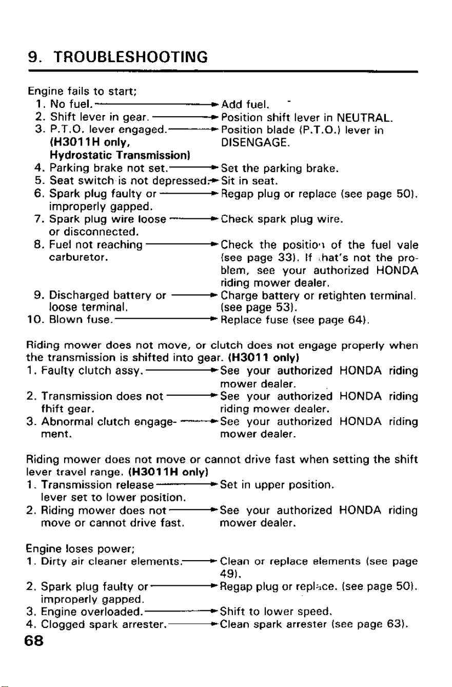
9. TROUBLESHOOTING
Engine fails to start;
1. No fuel.
WAdd fuel. -
2. Shift lever in gear.
-Position shift lever in NEUTRAL.
3. P.T.O. lever engaged.-
Position blade (P.T.O.) lever in
(H3011 H only, DISENGAGE.
Hydrostatic Transmission)
4. Parking brake not set.- Set the parking brake.
5. Seat switch.is not depressed-sit in seat.
6. Spark plug faulty or -
Regap plug or replace (see page 50).
improperly gapped.
7. Spark plug wire loose
-Check spark plug wire.
or disconnected.
8. Fuel not reaching
~Check the positiolr of the fuel vale
carburetor. (see page 33). If /hat’s not the pro-
blem, see your authorized HONDA
riding mower dealer.
9. Discharged battery or -Charge battery or retighten terminal.
loose terminal.
(see page 53).
10. Blown fuse. *Replace fuse (see page 64).
Riding mower does not move, or clutch does not engage properly when
the transmission is shifted into gear. (H3011 only)
1. Faulty clutch assy.
&See your authorized HONDA riding
mower dealer.
2. Transmission does not -
See your authorized HONDA riding
fhift gear.
riding mower dealer.
3. Abnormal clutch engage-
-See your authorized HONDA riding
ment.
mower dealer.
Riding mower does not move or cannot drive fast when setting the shift
lever travel range. (H3011H only)
1. Transmission release-
Set in upper position.
lever set to lower position.
2. Riding mower does not
-See your authorized HONDA riding
move or cannot drive fast.
mower dealer.
Engine loses power;
1. Dirty air cleaner elements.-
Clean or replace elements (see page
49).
2. Spark plug faulty or
-Regap plug or rep&e. (see page 50).
improperly gapped.
3. Engine overloaded.
WShift to lower speed.
4. Clogged spark arrester.
-Clean spark arrester (see page 63).
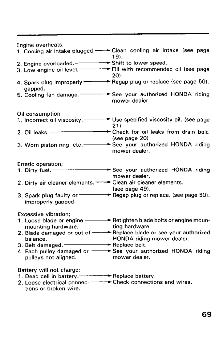
Engine overheats;
1. Cooling air intake plugged.
-Clean cooling air intake (see page
19).
2. Engine overloaded.
* Shift to lower speed.
3. Low engine oil level.
-Fill with recommended oil (see page
20).
4. Spark plug improperly
- Regap plug or replace (see page 50).
gapped.
5. Cooling fan damage.
-See your authorized HONDA riding
mower dealer.
Oil consumption
1. Incorrect oil viscosity.-
Use specified viscosity oil. (see page
21)
2. Oil leaks.
) Check for oil leaks from drain bolt.
(see page 20)
3. Worn piston ring, etc.
-See your authorized HONDA riding
mower dealer.
Erratic operation;
1. Dirty fuel.
*See your authorized HONDA riding
mower dealer.
2. Dirty air cleaner elements.
-Clean air cleaner elements.
(see page 49).
3. Spark plug faulty or
- Regap plug or replace. (see page 50).
improperly gapped.
Excessive vibration;
1. Loose blade or engine
- Retighten blade bolts or engine moun-
mounting hardware.
ting hardware.
2. Blade damaged or out of
-Replace blade or see your authorized
balance.
HONDA riding mower dealer.
3. Belt damaged.
c Replace belt.
4. Each pulley damaged or
-See your authorized HONDA riding
pulleys not aligned.
mower dealer.
Battery will not charge;
1. Dead cell in battery.-
Replace battery.
2. Loose electrical connec-
-Check connections and wires.
tions or broken wire.
69
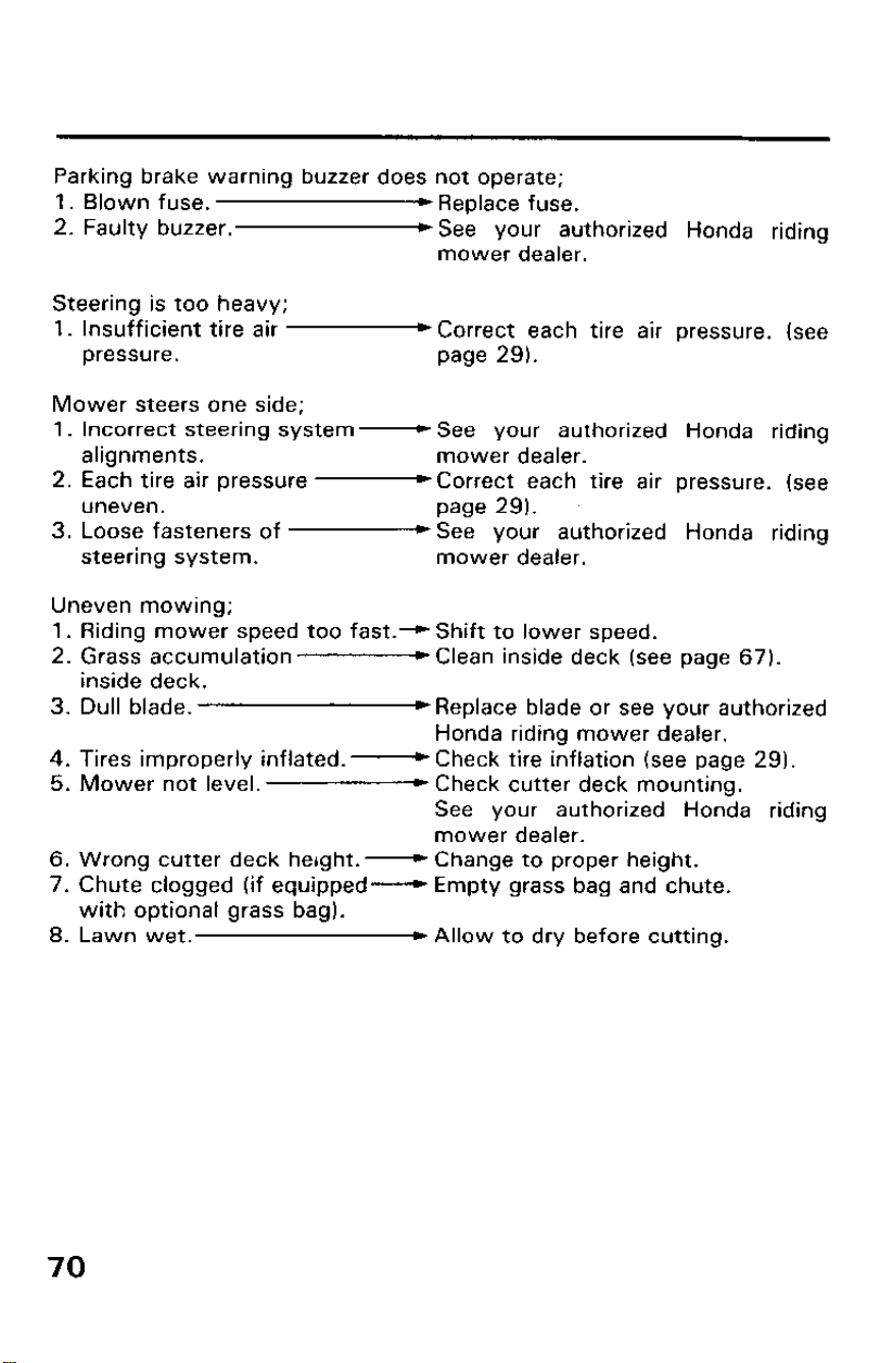
Parking brake warning buzzer does not operate;
1. Blown fuse.
*Replace fuse.
2. Faulty buzzer. )See your authorized Honda riding
mower dealer.
Steering is too heavy;
1. Insufficient tire air
pressure.
Mower steers one side;
*Correct each tire air pressure. (see
page 29).
1. Incorrect steering system-
See your authorized Honda riding
alignments.
mower dealer.
2. Each tire air pressure
-Correct each tire air pressure. (see
uneven.
page 29).
3. Loose fasteners of
*See your authorized Honda riding
steering system.
mower dealer.
Uneven mowing;
1. Riding mower speed too fast.--.) Shift to lower speed.
2. Grass accumulation-
Clean inside deck (see page 67).
inside deck.
3. Dull blade.
~Replace blade or see your authorized
Honda riding mower dealer.
4. Tires improperly inflated.-
Check tire inflation (see page 29).
5. Mower not level.
) Check cutter deck mounting.
See your authorized Honda riding
mower dealer.
6. Wrong cutter deck herght.-
Change to proper height.
7. Chute clogged (if equipped-
Empty grass bag and chute.
with optional grass bag).
8. Lawn wet.
) Allow to dry before cutting.
70
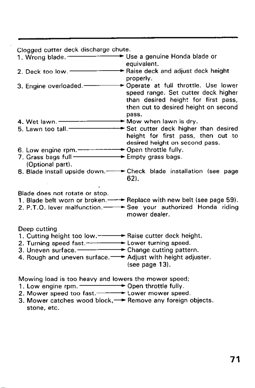
Clogged cutter deck discharge chute.
1. Wrong blade.
* Use a genuine Honda blade or
equivalent.
2. Deck too low.
* Raise deck and adjust deck height
properly.
3. Engine overloaded.
+ Operate at full throttle. Use lower
speed range. Set cutter deck higher
than desired height for first pass,
then cut to desired height on second
pass.
4. Wet lawn.
) Mow when lawn is dry.
5. Lawn too tall.
) Set cutter deck higher than desired
height for first pass, then cut to
desired height on second pass.
6. Low engine rpm.
) Open throttle fully.
7. Grass bags full
) Empty grass bags.
(Optional part).
8. Blade install upside down.-
Check blade installation (see page
62).
Blade does not rotate or stop.
1. Blade belt worn or broken.-
Replace with new belt (see page 59).
2. P.T.O. lever malfunction.-
See your authorized Honda riding
mower dealer.
Deep cutting
1. Cutting height too low.-
Raise cutter deck height.
2. Turning speed fast..
Lower turning speed.
3. Uneven surface.
* Change cutting pattern.
4. Rough and uneven surface.-
Adjust with height adjuster.
(see page 131.
Mowing load is too heavy and lowers the mower speed;
1. Low engine rpm.
) Open throttle fully.
2. Mower speed too fast.-
Lower mower speed.
3. Mower catches wood block
,-+ Remove any foreign objects.
stone, etc.
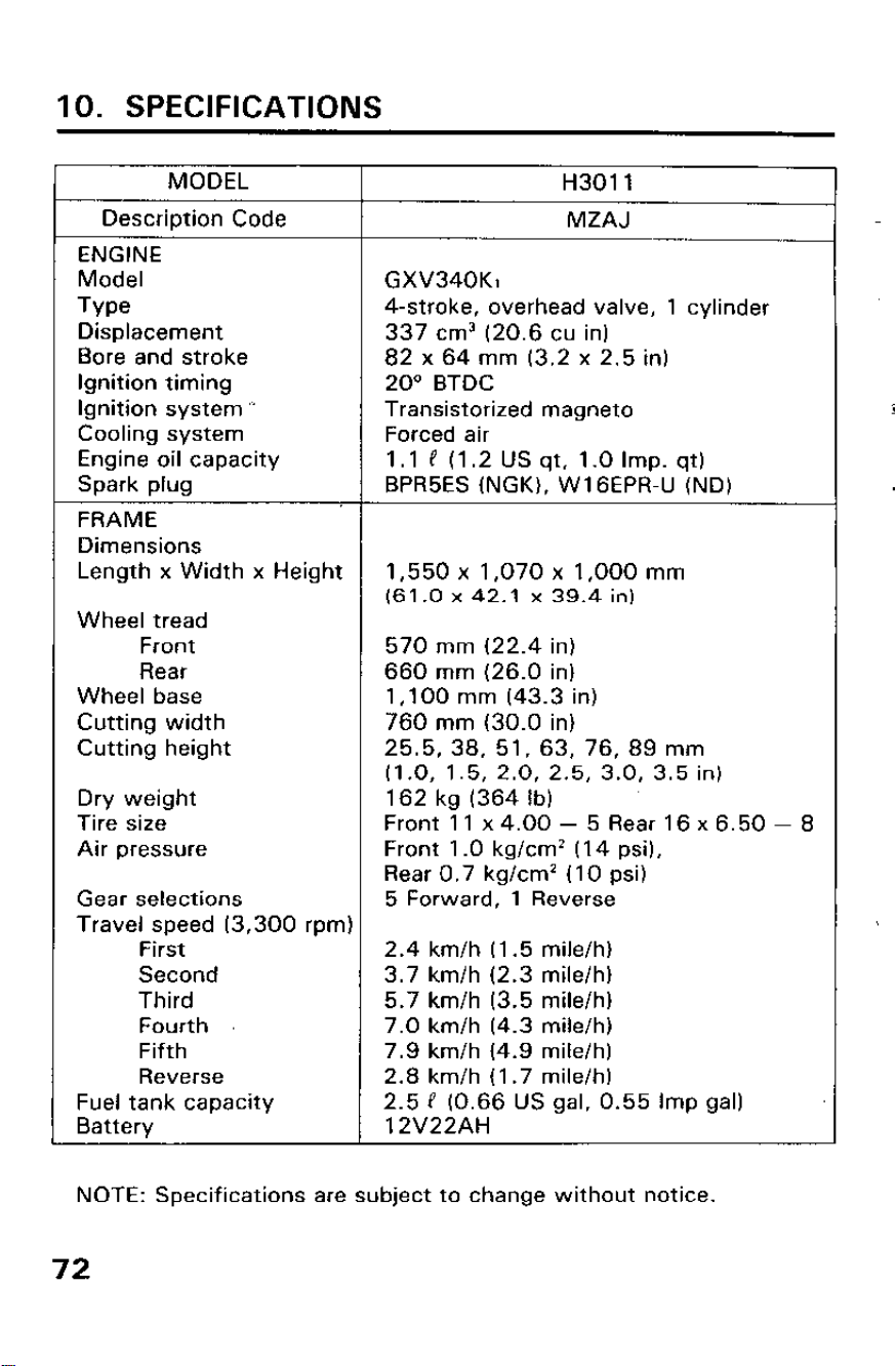
IO. SPECIFICATIONS
MODEL
H3011
Description Code
MZAJ
ENGINE
Model GXV340Kl
Type
4-stroke, overhead valve, 1 cylinder
Displacement 337 cm3 (20.6 cu in)
Bore and stroke
82 x 64 mm (3.2 x 2.5 in)
Ignition timing
20” BTDC
Ignition system * Transistorized magneto
Cooling system Forced air
Engine oil capacity 1 .l P (I .2 US qt. 1 .O Imp. qt)
Spark plug BPR5ES (NGK), WIGEPR-U (ND)
FRAME
Dimensions
Length x Width x Height 1,550 x 1,070 x 1,000 mm
(61.0 x 42.1 x 39.4 in)
Wheel tread
Front
570 mm (22.4 in)
Rear
660 mm (26.0 in)
Wheel base
1,100 mm (43.3 in)
Cutting width
760 mm (30.0 in)
Cutting height 25.5, 38, 51, 63, 76, 89 mm
(1.0, 1.5, 2.0, 2.5, 3.0, 3.5 in)
Dry weight 162 kg (364 lb)
Tire size
Front 11 x 4.00 - 5 Rear 16 x 6.50 - 8
Air pressure
Front 1 .O kg/cm2 (14 psi),
Rear 0.7 kg/cm2 (IO psi)
Gear selections
5 Forward, 1 Reverse
Travel speed (3,300 rpm)
First
2.4 km/h (1.5 mile/h)
Second
3.7 km/h (2.3 mile/h)
Third
5.7 km/h (3.5 mile/h)
Fourth
7.0 km/h (4.3 mile/h)
Fifth
7.9 km/h (4.9 mile/h)
Reverse
2.8 km/h (1.7 mile/h)
Fuel tank capacity
2.5 P (0.66 US gal, 0.55 Imp gal)
Battery
12V22AH
NOTE: Specifications are subject to change without notice.
72
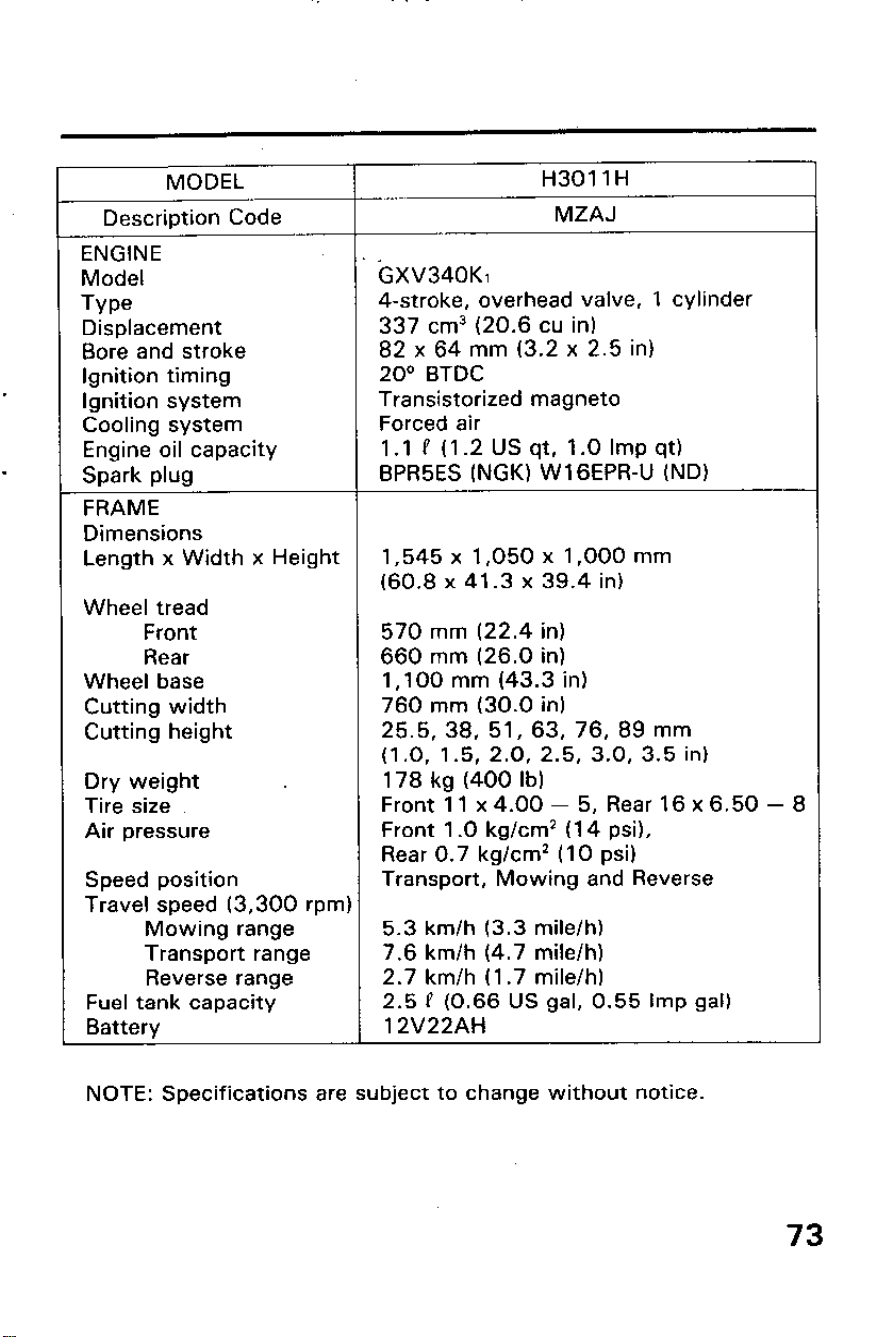
MODEL
H3011 H
Description Code
MZAJ
ENGINE
.
Model
GXV340Kl
Type
4-stroke, overhead valve, 1 cylinder
Displacement
337 cm3 (20.6 cu in)
Bore and stroke
82 x 64 mm (3.2 x 2.5 in)
Ignition timing 20“ BTDC
Ignition system
Transistorized magneto
Cooling system Forced air
Engine oil capacity
1.1 P (1.2 US qt, 1.0 Imp qt)
Spark plug
BPR5ES (NGK) WIGEPR-U (ND)
FRAME
Dimensions
Length x Width x Height 1,545 x 1,050 x 1,000 mm
(60.8 x 41.3 x 39.4 in)
Wheel tread
Front
570 mm (22.4 in)
Rear
660 mm (26.0 in)
Wheel base 1,100 mm (43.3 in)
Cutting width 760 mm (30.0 in)
Cutting height 25.5, 38, 51, 63, 76, 89 mm
(1.0, 1.5, 2.0, 2.5, 3.0, 3.5 in)
Dry weight . 178 kg (400 lb)
Tire size Front 11 x 4.00 - 5, Rear 16 x 6.50 - 8
Air pressure Front 1 .O kg/cm* (I 4 psi),
Rear 0.7 kg/cm’ (IO psi)
Speed position Transport, Mowing and Reverse
Travel speed (3,300 rpm)
Mowing range 5.3 km/h (3.3 mile/h)
Transport range
7.6 km/h (4.7 mile/h)
Reverse range 2.7 km/h (I .7 mile/h)
Fuel tank capacity 2.5 P (0.66 US gal, 0.55 Imp gal)
Battery 12V22AH
NOTE: Specifications are subject to change without notice.
73
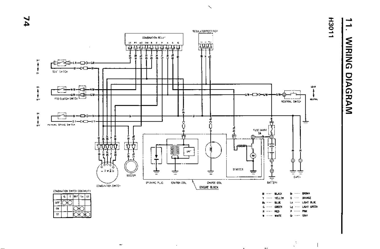
11. WIRING DIAGRAM
H3011
r
-
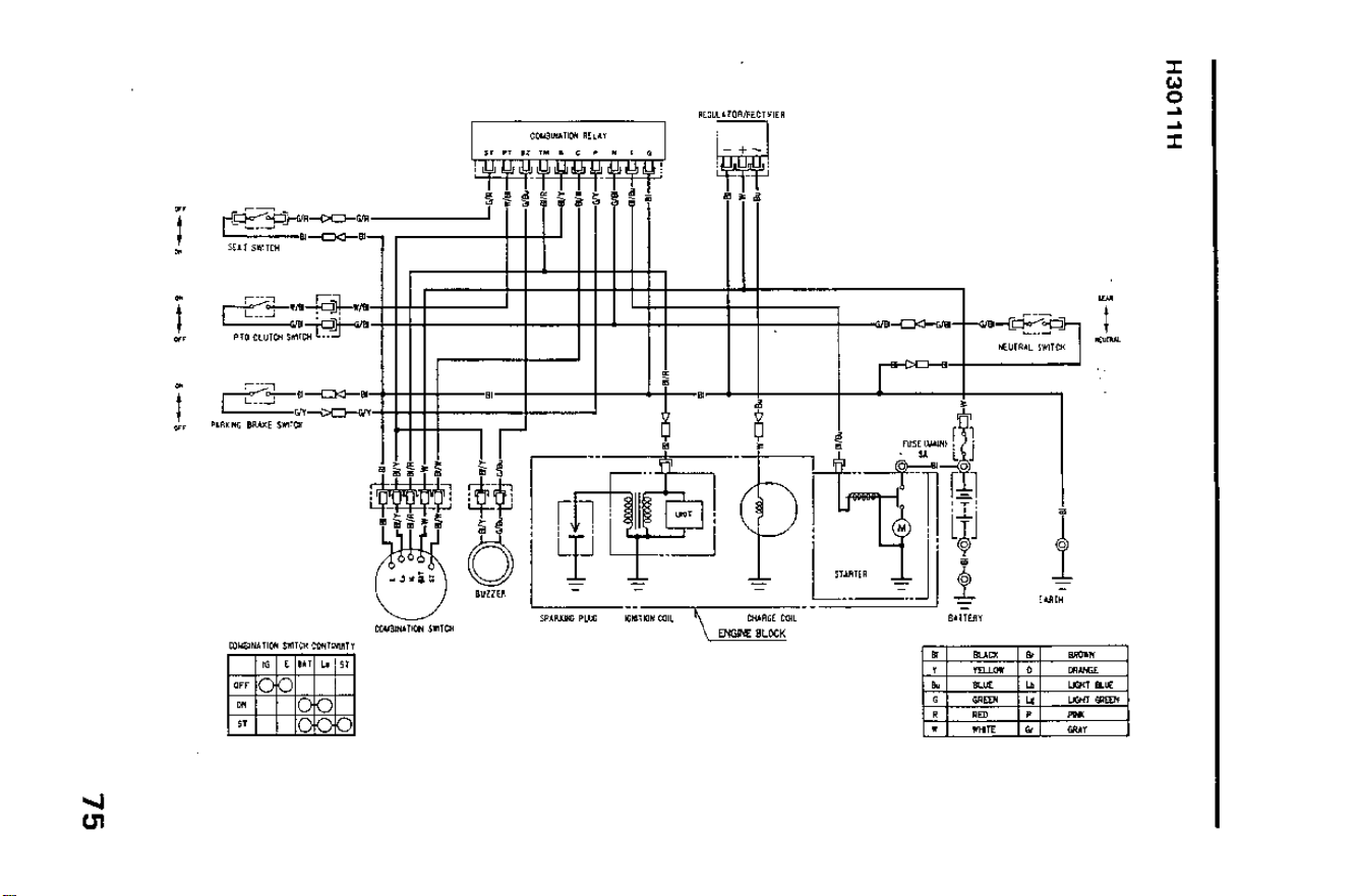
H3011 H
-t
-t
T
75
12. WARRANTY SERVICE
Owner Satisfaction
Your satisfaction and goodwill are important to your dealer and to us. All
Honda warranty details are explained in the Distributor’s Limited
Warranty.
Normally, any problems concerning the product will be handled by your
-
dealer’s service department. If you have a warranty problem that has not
been handled to your satisfaction, we suggest you take the following
action:
l Discuss your problem with a member of dealership managemert. Often
complaints can be quickly resolved at that level. If the problem has
already been reviewed with the Service Manager, contact the owner of
the dealership or the General Manager.
l If your problem still has not been resolved to your satisfaction, contact:
American Honda Motor Co., Inc.
P.O. Box 50
Gardena, California 90247-0805
Telephone: (213) 604-2400
We will need the following information in order to assist you:
- Your name, address, and telephone number
- Product model and serial number
- Date of purchase
- Dealer name and address
- Nature of problem
After reviewing all the facts involved, you will be advised of what action
can be taken. Please bear in mind that your problem will likely be resolved
at the dealership, using the dealer’s facilities, equipment, and personnel,
so it is very important that your initial contact be with the dealer.
Your purchase of a Honda product is greatly appreciated by both your
dealer and American Honda Motor Co., Inc. We want to assist you in every
way possible to assure your complete satisfaction with your purchase.
76

Current customer service contact information:
United States, Puerto Rico, and U.S. Virgin Islands:
Honda Power Equipment dealership personnel are trained professionals. They should
be able to answer any question you may have. If you encounter a problem that your
dealer does not solve to your satisfaction, please discuss it with the dealership's
management. The Service Manager or General Manager can help. Almost all problems
are solved in this way.
If you are dissatisfied with the decision made by the dealership's management, contact
the Honda Power Equipment Customer Relations Office. You can write:
American Honda Motor Co., Inc.
Power Equipment Division
Customer Relations Office
4900 Marconi Drive
Alpharetta, GA 30005-8847
Or telephone: (770) 497-6400 M-F, 8:30 am - 7:00 pm EST
When you write or call, please provide the following information:
• Model and serial numbers
• Name of the dealer who sold the Honda power equipment to you
• Name and address of the dealer who services your equipment
• Date of purchase
• Your name, address, and telephone number
• A detailed description of the problem


Printed on
Recycled Paper
O Manualwner's
KINKOS
100.2002.08
PRINTED IN U.S.A.
31763800
00X31-763-8002
Riding Mower
H3011 • H3011H
©1989 Honda Motor Co., LTD. — All Rights Reserved