

Repair Guide
Basic Model
LS27CG510ENXZA
Applicable Model
LS**CG510ENXZA
Ver. 1.0

Contents
1. Precautions
1-1. Safety Precautions ....................................................................................................................................... 1-1
1-1-1. Warnings ............................................................................................................................................1-1
1-1-2. Servicing the Product ..................................................................................................................1-1
1-1-3. Fire and Shock Hazard .................................................................................................................1-1
1-1-4. Product Safety Notices ............................................................................................................... 1-2
1-2. Servicing Precautions ................................................................................................................................. 1-3
1-2-1. General Servicing Precautions ................................................................................................... 1-3
1-3. Electrostatically Sensitive Devices (ESD) Precautions ...................................................................... 1-4
1-4. Installation Precautions ............................................................................................................................ 1-5
2. Disassembly and Reassemble
2-1. Stand Reassemble..................................................................................................................................... 2-1
2-2. Cover Rear Disassembly .......................................................................................................................... 2-2
2-3. Jog PCB Disassembly ............................................................................................................................... 2-4
2-4. Main PCB Disassembly ............................................................................................................................. 2-5
Self-Repair Legal Disclosures
Usage Notices
All content and information provided in this document, are subject to change without notice at any time. This
document is intended for informational purposes only. You can download a copy of your product Manuals and
Software. If you don’t understand the information provided in this document or have any doubts about your
ability to safely undertake the repair, visit https://www.samsung.com/us/support or call 1-800-Samsung for
other repair options.
Precautions for Repair
Samsung is not liable for any damage or defect determined to be caused by repair by a non-authorized service
provider, self-repair or non-professional repair of the product. Samsung is not liable for any resulting damage to
the product, person, or property, or any injury or other product safety issue caused by any attempt to repair the
product by any person other than a Samsung- authorized service provider. Any damage or defect to product
resulting from a repair, or an attempt to repair, the product by any person other than a Samsung certified service
provider will not be covered by the warranty.
Visit Samsung.com to view the product information, repair guides, related material, and safety information.
·
Ensure that you have read and understood the repair guide and related safety information
before attempting a repair and that you reference the guide ensuring that:
o
The repair in conducted in a safe and clean area.
o
Backup copies of all important data stored in the device are made.
o
The product is turned off and unplugged from the power source
o
ESD precautions are taken where required.
o
The recommended tools and personal protective equipment are used.
o
The repair is made using Samsung genuine parts.
o
Where required, the recommended post repair testing and calibration is conducted.
o
Used parts are appropriately handled and disposed of.

Terms of Use:
General Terms: This manual contains confidential and proprietary information of Samsung Electronics Co., Ltd.
(“Samsung”). All text, graphics, user interfaces, visual interfaces, photographs, trademarks, and logos
(collectively, “Content”), including but not limited to the design, structure, selection, coordination, “look and
feel” and arrangement of such Content, contained in this manual is owned, controlled or licensed by or to
Samsung, and is protected by trade dress, copyright, patent and trademark laws, and various other intellectual
property rights and unfair competition laws.
No part of this manual or the Content may be copied, reproduced, republished, uploaded, posted, publicly
displayed, encoded, translated, transmitted or distributed in any way (including “mirroring”) to anyone, any
entity, any other computer, server, Web site or other medium for publication or distribution or for any commercial
purpose, without Samsung’s express prior written consent.
Limitation of Liability. WHILE SAMSUNG MAKES ALL REASONABLE EFFORTS TO INSURE THAT ALL
INFORMATION IN THIS MANUAL IS CORRECT, SAMSUNG DOES NOT ASSUME ANY RESPONSIBILITY FOR THE
ACCURACY OR COMPLETENESS OF ANY INFORMATION CONTAINED IN THIS MANUAL. SAMSUNG PROVIDES
INFORMATION AND MATERIALS CONTAINED IN THIS MANUAL TO YOU ON AN “AS IS” BASIS WITHOUT
WARRANTY OF ANY KIND, EITHER EXPRESS OR IMPLIED. SAMSUNG SPECIFICALLY DISCLAIMS ANY LIABILITY
FOR ANY DIRECT, INDIRECT, INCIDENTAL, CONSEQUENTIAL OR SPECIAL DAMAGES ARISING OUT OF OR IN
ANY WAY CONNECTED WITH YOUR ACCESS TO OR USE OF THE INFORMATION IN THIS MANUAL, INCLUDING BUT
NOT LIMITED TO ANY LOSS OR DAMAGE CAUSED BY YOUR RELIANCE ON INFORMATION OBTAINED THROUGH
THIS MANUAL. Some jurisdictions do not allow exclusion of certain warranties or limitations of liability, so the
above limitations or exclusions may not apply to you. Samsung’s liability in any case shall be limited to the
greatest extent permitted by law.
Samsung reserves the right, at its sole discretion, to change, modify, add or remove portions of any part of this
manual at any time. It is your responsibility to check the manual periodically for changes. Your use of the manual
will mean that you accept and agree to these Terms of Use, including the Limitation of Liability and the
Dispute Resolution Agreement terms set out at https://www.samsung.com/us/support/legal/mobile/
#dispute- resolution-agreement. If you do not agree to comply with these Terms of use, in whole or in part,
please stop using this manual immediately.
This Service Manual is a property of Samsung Electronics
Co.,Ltd. Any unauthorized use of Manual can be punished under
applicable International and/or domestic law.
© 2024 Samsung Electronics
Co.,Ltd. All rights reserved.
Printed in Korea
P/N: BN82-01058A-00
Precautions
1.
Precautions
1-1. Safety Precautions
•
Follow these safety, servicing and ESD precautions to prevent damage and to protect against potential hazards such
as electrical shock.
1-1-1. Warnings
WARNING
For continued safety, do not attempt to modify the circuit board.
Disconnect the AC power and DC power jack before servicing.
Discharge residual voltage before removing or handling the printed circuit board assembly(PCBA)
1-1-2. Servicing the Product
1.
When servicing the Product, Disconnect the AC line cord from the AC outlet.
2.
It is essential that service technicians have an accurate voltage meter available at all times. Check the calibration of
this meter periodically.
1-1-3. Fire and Shock Hazard
•
After completion of repair, perform the following safety
checks:
1.
Inspect each lead dress to make certain that the leads are not pinched or that hardware is not lodged between the
chassis and other metal parts in the monitor.
2.
Inspect all protective devices such as nonmetallic control knobs, insulating materials, cabinet backs, adjustment and
compartment covers or shields, isolation resistorcapacitor networks, mechanical insulators, etc.
3.
Design Alteration Warning: Never alter or add to the mechanical or electrical design of the unit.
Example: Do not add auxiliary audio or video connectors. Such alterations might create a safety hazard. Also, any design
changes or additions will void the manufacturer’s warranty.
4.
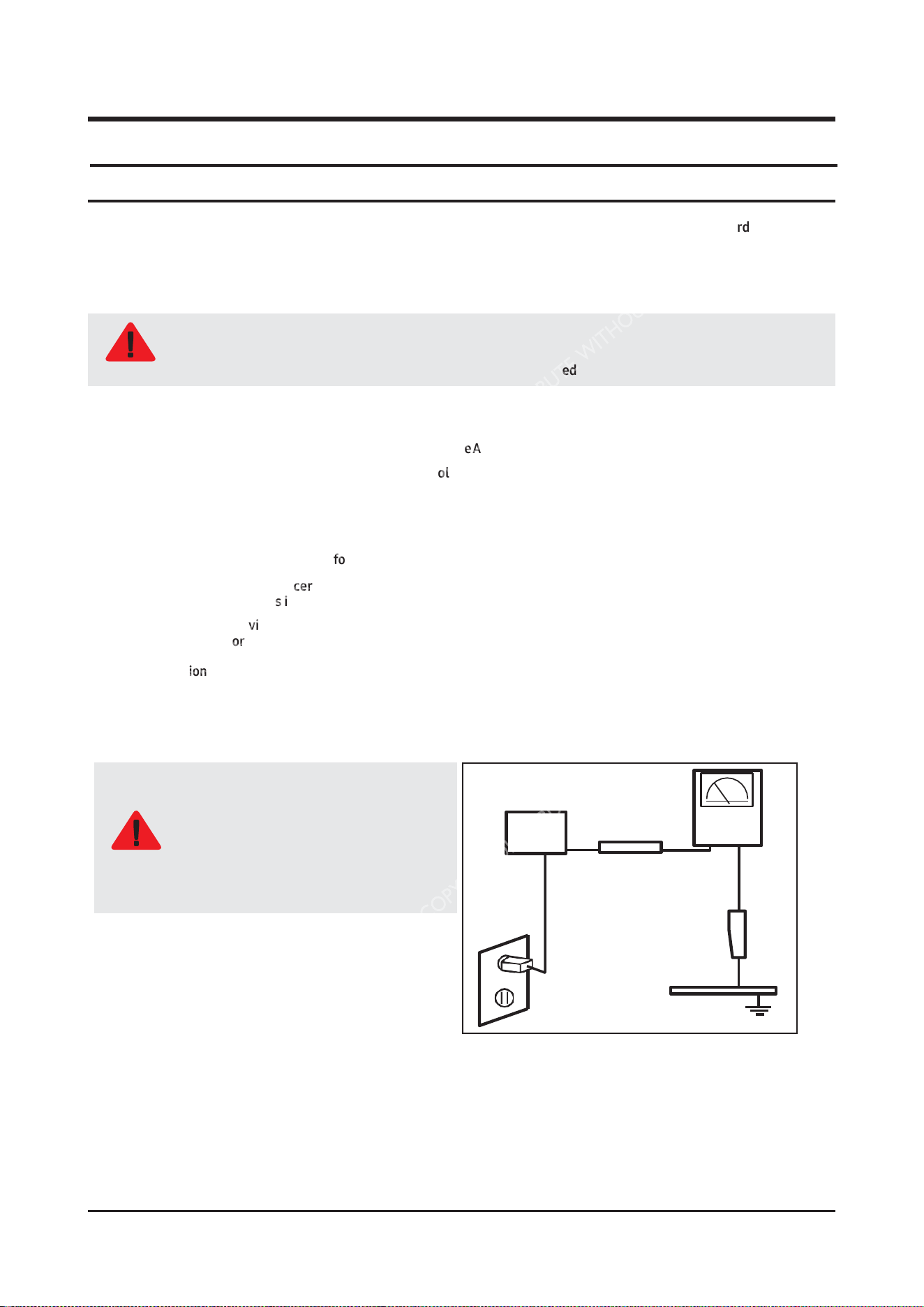
Leakage Current Hot Check:
Do not use an isolation transformer during
this test.
Use a leakage current tester or a metering
system that complies with American
National Standards Institute (ANSI C101.1,
WARNING
Leakage Current for Appliances), and
Underwriters Laboratories (UL Publication
UL1410, 59.7).
(READING
SHOULD)
NOT BE ABOVE 0.5mA
LEAKAGE
DEVICE
CURRENT
UNDER
TESTER
TEST
TEST ALL EXPOSED
METAL SURFACES
2-WIRE
CORD
ALSO TEST WITH PLUG
REVERSED (USING AC
ADAPTER
PLUG
AS
EARTH
REQUIRED)
GROUND
5.
With the unit completely reassembled, plug the AC line cord directly into a 120V AC outlet. With the unit’s AC switch first in
the ON position and then OFF, measure the current between a known earth ground (metal water pipe, conduit, etc.) and all
exposed metal parts, including: metal cabinets, screwheads and control shafts.
The current measured should not exceed 0.5 milliamp.
Reverse the power-plug prongs in the AC outlet and repeat the test.
1-1
Precautions
6. Observe the original lead dress, especially near the following areas: Antenna wiring, sharp edges, and especially the AC and
high voltage power supplies. Always inspect for pinched, out-of-place, or frayed wiring. Do not change the spacing between
components and the printed circuit board. Check the AC power cord for damage. Make sure that no wires or components touch
thermally hot parts.
1-1-4. Product Safety Notices
Some electrical and mechanical parts have special safetyrelated characteristics which are often not evident from visual
inspection. The protection they give may not be obtained by replacing them with components rated for higher voltage, wattage,
etc. Parts that have special safety characteristics are identified by on Disassembly and Reassembly. A substitute
replacement that does not have the same safety characteristics as the recommended replacement part might create shock, fire
and/or other hazards. Product safety is under review continuously and new instructions are issued whenever appropriate.
WARNING
Wear protective equipment(gloves, safety goggles, etc) all time and discharge residual voltage from printed
circuit board assembly(PCBA) before removing or handling to prevent injuries and electrical shock that may
occur during product disassembly/repair.
1-
2
1-2. Servicing Precautions
Precautions
WARNING
An electrolytic capacitor installed with the wrong polarity might explode.
CAUTION
Before servicing units covered by this service manual, read and follow the Safety Precautions section of this
manual.
NOTE
If unforeseen circumstances create conflict between the following servicing precautions and any of the safety
precautions, always follow the safety precautions.
NOTE
Following the repair by a non-authorised service provider, self-repair or non-professional repair of the product,
Samsung is not liable for any damage to the product, any injury or any other product safety issue caused by
any attempt to repair the product which does not carefully follow these repair and maintenance instructions.
Any damage to the product caused by an attempt to repair the product by any person other than a Samsung
certified service provider will not be covered by the warranty
1-2-1. General Servicing Precautions
1.
Always unplug the unit’s AC power cord from the AC power source and disconnect the DC Power Jack before attempting to:
(a) remove or reinstall any component or assembly, (b) disconnect PCB plugs or connectors, (c) connect a test component in
parallel with an electrolytic capacitor.
2.
Some components are raised above the printed circuit board for safety. An insulation tube or tape is sometimes used. The
internal wiring is sometimes clamped to prevent contact with thermally hot components. Reinstall all such elements to their
original position.
3.
After servicing, always check that the screws, components and wiring have been correctly reinstalled. Make sure that the area
around the serviced part has not been damaged.
4.
Check the insulation between the blades of the AC plug and accessible conductive parts (examples: metal panels, input
terminals and earphone jacks).
5.
Insulation Checking Procedure: Disconnect the power cord from the AC source and turn the power switch ON. Connect an
insulation resistance meter (500 V) to theblades of the AC plug. The insulation resistance between each blade of the AC plug and
accessible conductive parts (see above) should be greater than 1 megohm.
6.
Always connect a test instrument’s ground lead to the instrument chassis ground before connecting the positive lead; always
remove the instrument’s ground lead last.
1-
3
Precautions
1-3. Electrostatically Sensitive Devices (ESD) Precautions
Some semiconductor (solid state) devices can be easily damaged by static electricity. Such components are commonly
called Electrostatically Sensitive Devices (ESD). Examples of typical ESD are integrated circuits and some field-effect
transistors. The following techniques will reduce the incidence of component damage caused by static electricity.
1.
Immediately before handling any semiconductor components or assemblies, drain the electrostatic charge from your body by
touching a known earth ground. Alternatively, wear a discharging wrist-strap device. To avoid a shock hazard, be sure to
remove the wrist strap before applying power to the monitor.
2.
After removing an ESD-equipped assembly, place it on a conductive surface such as aluminum foil to prevent accumulation of an
electrostatic charge.
3.
Do not use freon-propelled chemicals. These can generate electrical charges sufficient to damage ESDs.
4.
Use only a grounded-tip soldering iron to solder or desolder ESDs.
5.
Use only an anti-static solder removal device. Some solder removal devices not classified as “anti-static” can generate electrical
charges sufficient to damage ESDs.
6.
Do not remove a replacement ESD from its protective package until you are ready to install it. Most replacement ESDs are
packaged with leads that are electrically shorted together by conductive foam, aluminum foil or other conductive materials.
7.
Immediately before removing the protective material from the leads of a replacement ESD, touch the protective material to the
chassis or circuit assembly into which the device will be installed.
8. Minimize body motions when handling unpackaged replacement ESDs. Motions such as brushing clothes together, or lifting
your foot from a carpeted floor can generate enough static electricity to damage an ESD.
1-
4
Be sure no power is applied to the chassis or circuit and observe all other safety precautions.
1-4. Installation Precautions
Precautions
CAUTION
1.
For safety reasons, more than a people are required for carrying the product.
2.
Keep the power cord away from any heat emitting devices, as a melted covering may cause fire or electric shock.
3.
Do not place the product in areas with poor ventilation such as a bookshelf or closet. The increased internal temperature may
cause fire.
4.
Do not install the product on a place that is shaking, tilted, unstable, or seriously vibrating. The product may drop to get damaged
or injure a person. If using the product in a highly vibrating place, it may be broken or cause fire.
5.
Bend the external antenna cable when connecting it to the product. This is a measure to protect it from being exposed to
moisture. Otherwise, it may cause a fire or electric shock.
6.
Make sure to turn the power off and unplug the power cord from the outlet before repositioning the product. Also check the
antenna cable or the external connectors if they are fully unplugged. Damage to the cord may cause fire or electric shock.
7.
Keep the antenna far away from any high-voltage cables and install it firmly. Contact with the highvoltage cable or the
antenna falling over may cause fire or electric shock.
8.
When installing the product, leave enough space between the product and the wall for ventilation purposes. A rise in
temperature within the product may cause fire.
9.
If an equipment is provided with a replaceable battery, and if replacement by an incorrect type could result in an explosion (for
example, with some lithium batteries), the following applies:
10.
Keep the packaging plastic wrapper out of children’s reach. If children play with it improperly, they may get suffocated.
11.
If installing the product on a display cabinet, shelf, desk, etc., keep the product from protruding on its lower side. If the product
falls, it may break or cause physical injury. Use only the display cabinet or shelf that fully covers the product.
•
Risk of explosion if battery is replaced by an incorrect type dispose of used batteries according to the
instructions.
•
Do not dispose of batteries in a fire.
•
Do not short circuit, disassemble or overheat the batteries.
•
Danger of explosion if battery is incorrectly replaced. Replace only with the same or equivalent type.
•
Do not be exposed to excessive heat such as sunshine, fire or the like.
1-5
Disassembly and Reassemble
2. Disassembly and Reassemble
This section of the service manual describes the disassembly and reassembly procedures for the Product.
CAUTION
1.
Disconnect the Product from the power source before disassembly.
2.
Follow these directions carefully.
-
Use the Samsung Open Jig and Cushion to remove the Rear Cover.
•
Open Jig Tool, Protection Cushion (curved models Only)
-
Recommended Torque for Cabinet/Stand screws : 10 ~ 12kgf
•
A strength of Torque can be changed depending on the
situation.
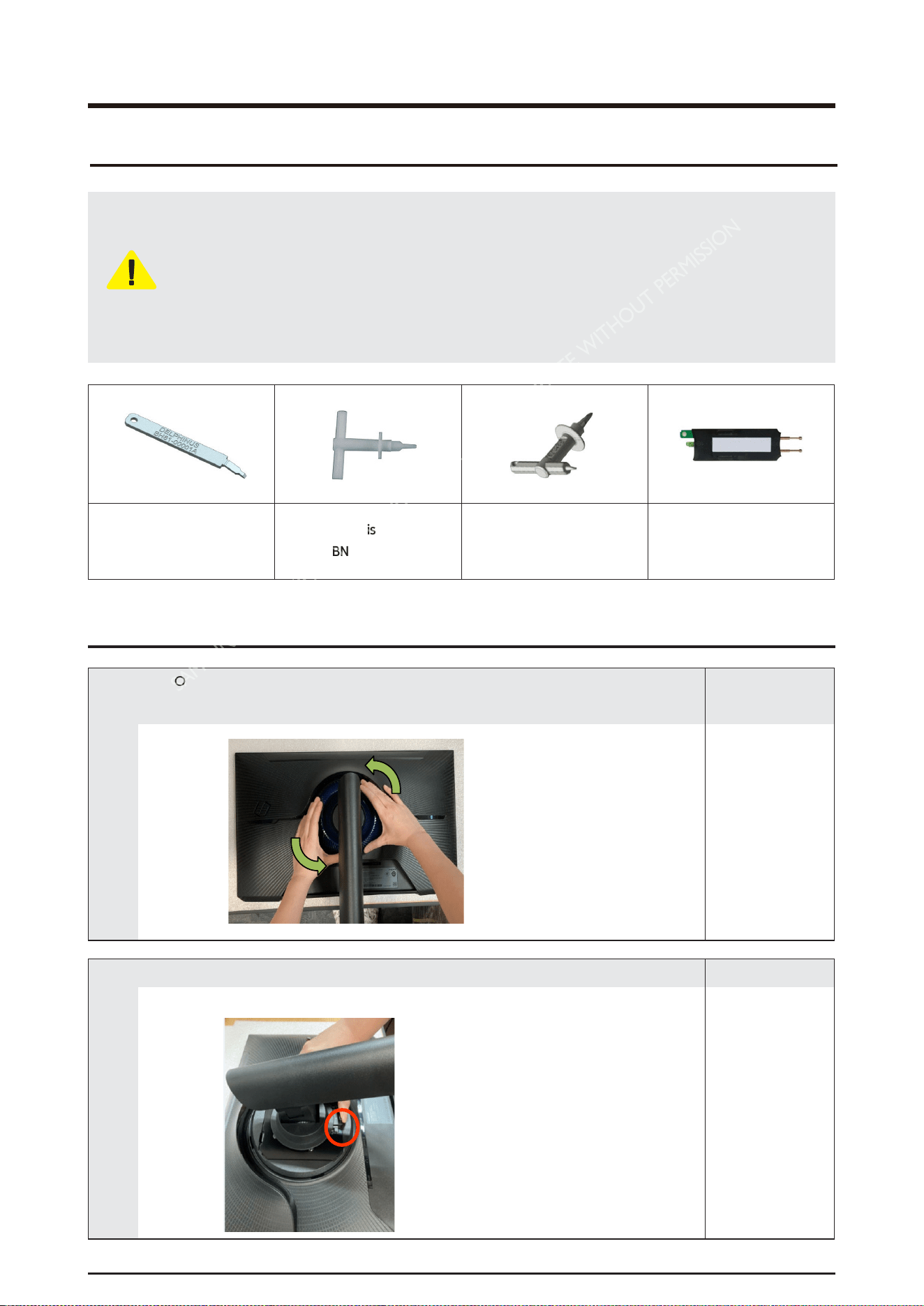
Delphinus
(BH81-00001A)
Assembly Misc P-jig-2017
(BN81-14946A)
Assembly Misc P-jig-2017
TV OCB Models
(BN81-14946B)
Service Jig-Capacitor
Discharge (BN81-16292A)
2-1. Stand
Resemble
1
•
COVER-REAR TOP counterclockwise, lift it up, and remove it in half.
* Prepare a cushion to prevent damage to the front.
Remark
2
•
After pushing up the stand fixing button, lift the stand and disassemble it.
Remark
2-1
Disassembly and Reassemble
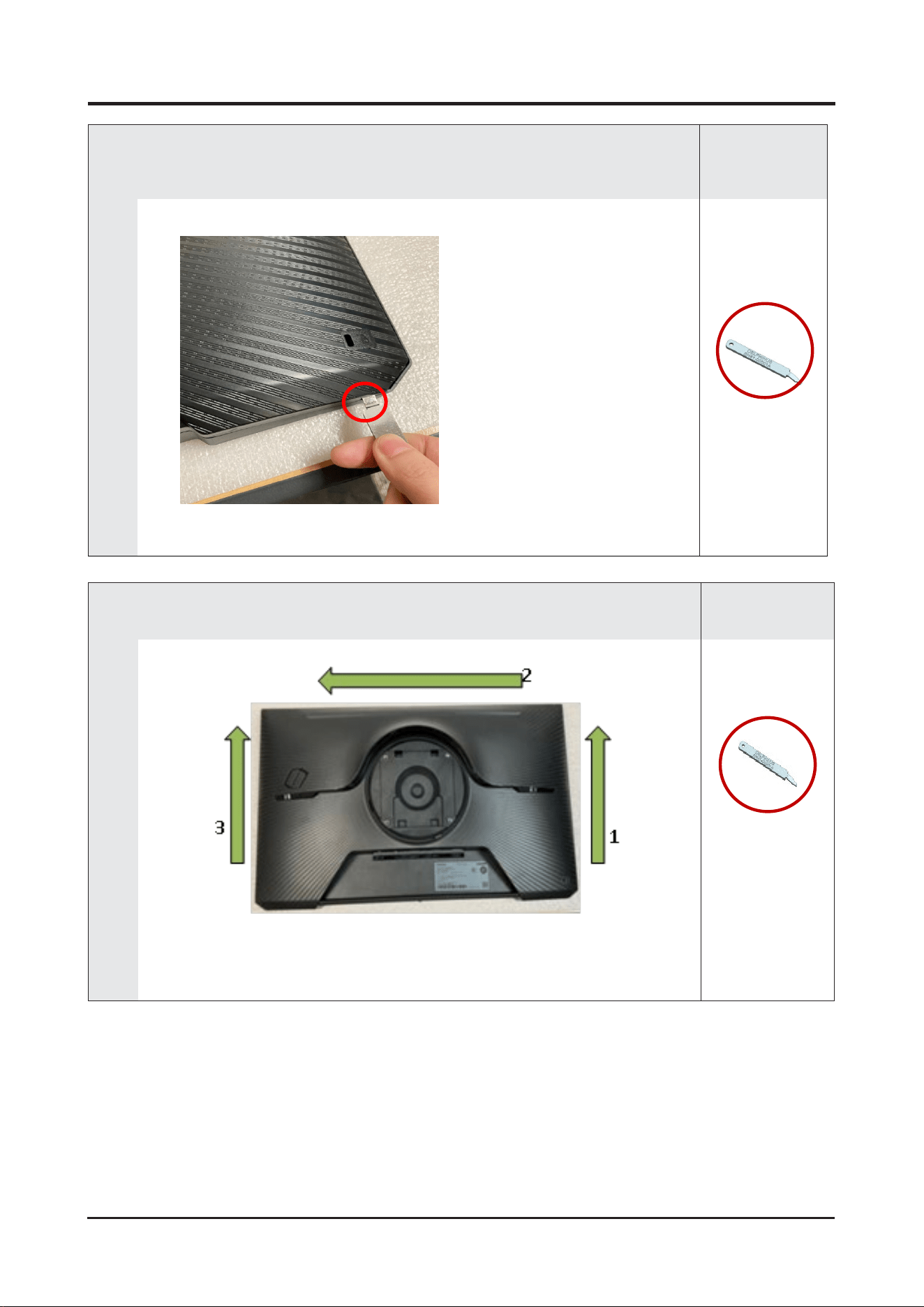
2-2.
Cover Rear Disassembly
1
•
Use the OPEN JIG to disassemble the rear cover LOCKING at corner.
Insert the JIG into the SET left/right lower disassembly groove and lift it until you hear the
disassembly sound to disassemble some snaps.
Remark
BH81-00001A
(Open
Jig)
2
•
Remove the rear cover by lifting it sequentially using a Delphinus jig in the direction as shown
in the figure
Remark
BH81-00001A
(Open
Jig)
2-2
Disassembly and Reassemble
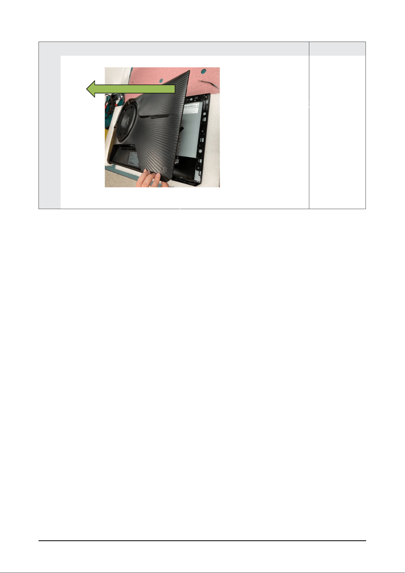
3
•
Remove the rear cover completely by lifting it in the direction of the arrow
Remark
2-3
Disassembly and Reassemble
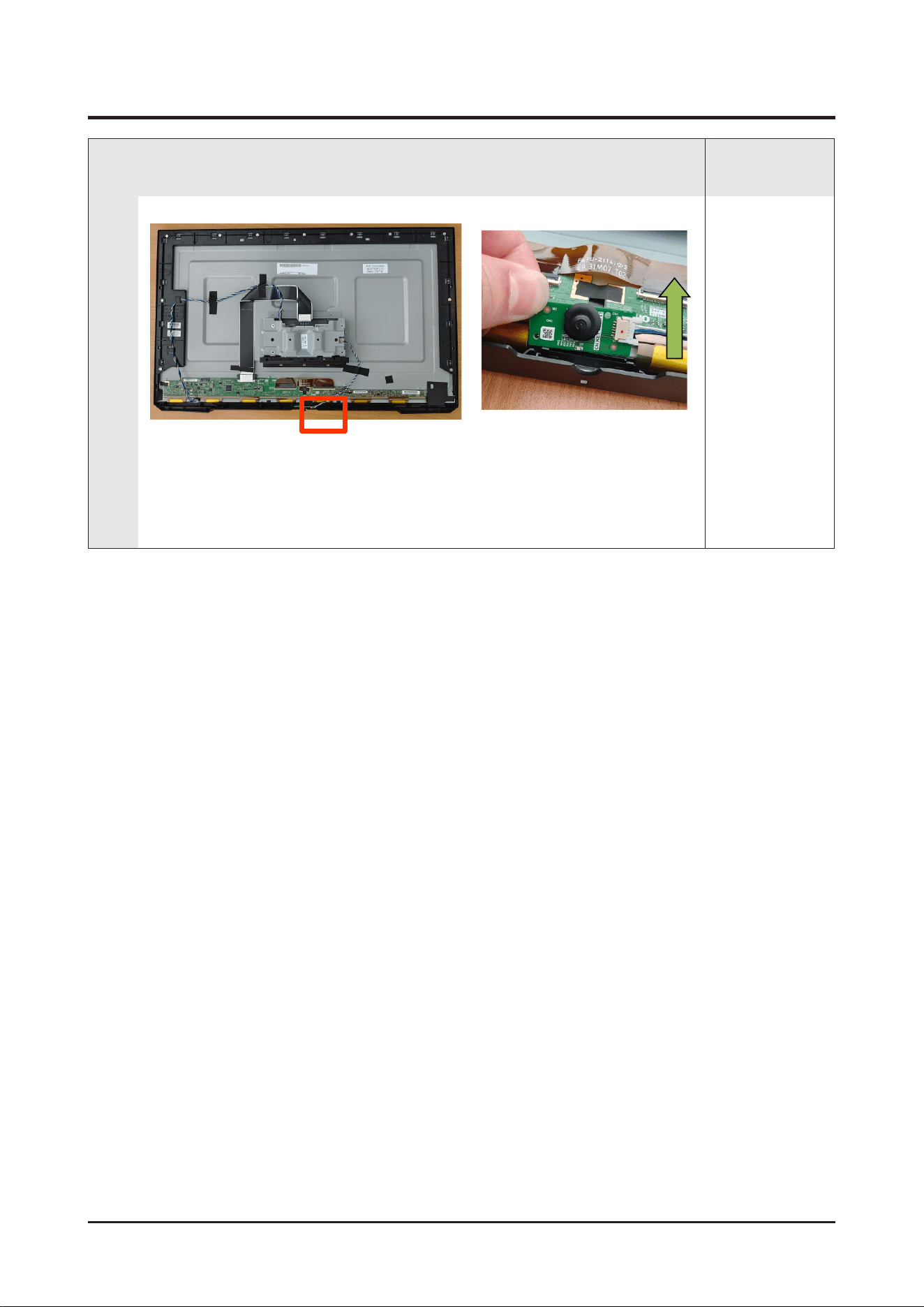
2-3.
Jog PCB Disassembly
1
•
Lift the JOG PCB in the direction of the arrow to
disassemble the button
Remark
2-4
Disassembly and Reassemble
2-4.
Main PCB
Disassembly
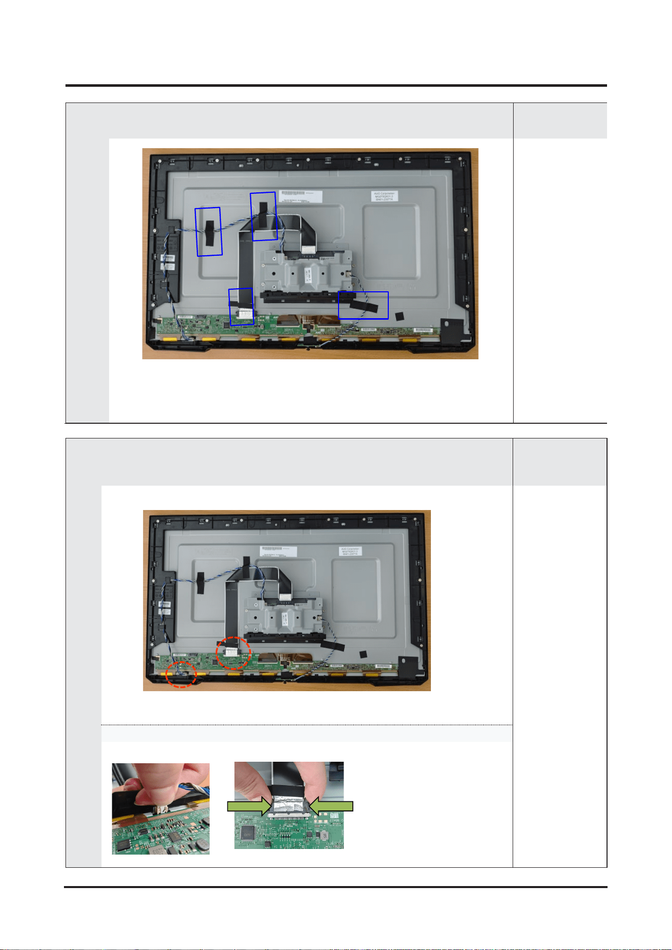
1
•
Remove the tape for wire route arrangement(4pcs)
Remark
2
•
Remove the two cables connected to the panel.
Remark
Press down on the connector housing to disassemble.
2-5
Disassembly and Reassemble
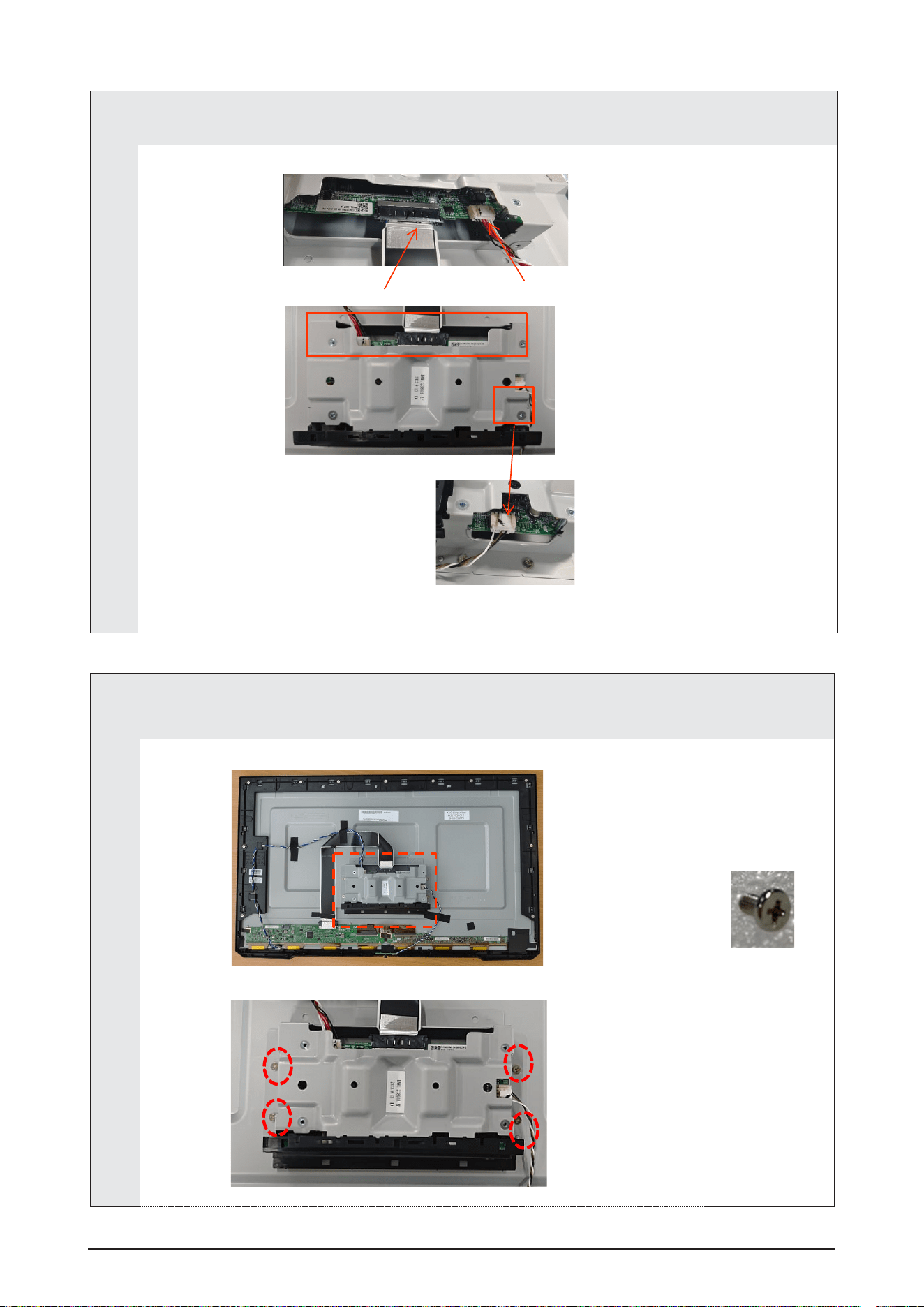
3
•
Remove the 3 cables connecter from Main PCB.
Remark
4
•
Remove the screw on the metal bracket(4pcs)
Remark
(BN81-21928A,
M3*5,4EA)
2-6
Disassembly and Reassemble
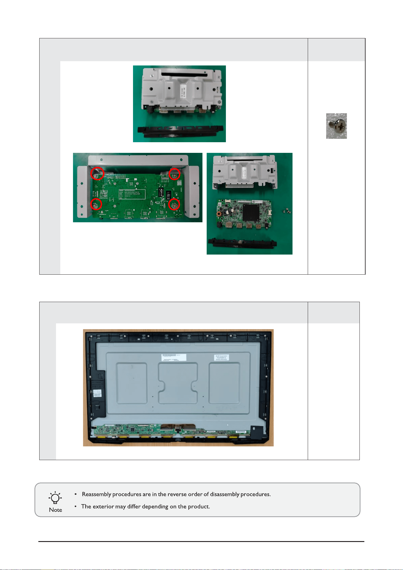
5
•
Separate Main PCB from metal bracket by removing the screws (4pcs)
Remark
(BN81-21928A,
M3*5,4EA)
2-7
6
•
Decomposition complete.
Remark