

A18FTSB0
Original instructions
2
90º90º
45º45º
p. 14
p. 17 p. 18
p. 10
p. 7
p. 7 p. 8
p. 6 p. 6
p. 4
p. 5
p. 16
p. 11 p. 12
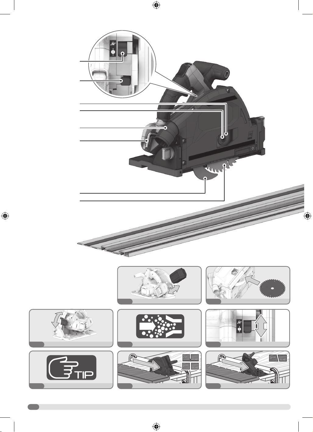
Front handle, insulated
gripping surface
Bevel 45º bypass lever
Track adjustment knob
Bevel indicator
0° bevel setting screw
Lock-o button
Track clamp
Depth of cut button
Negative 1º bypass slider
Handle, insulated
gripping surface
Track
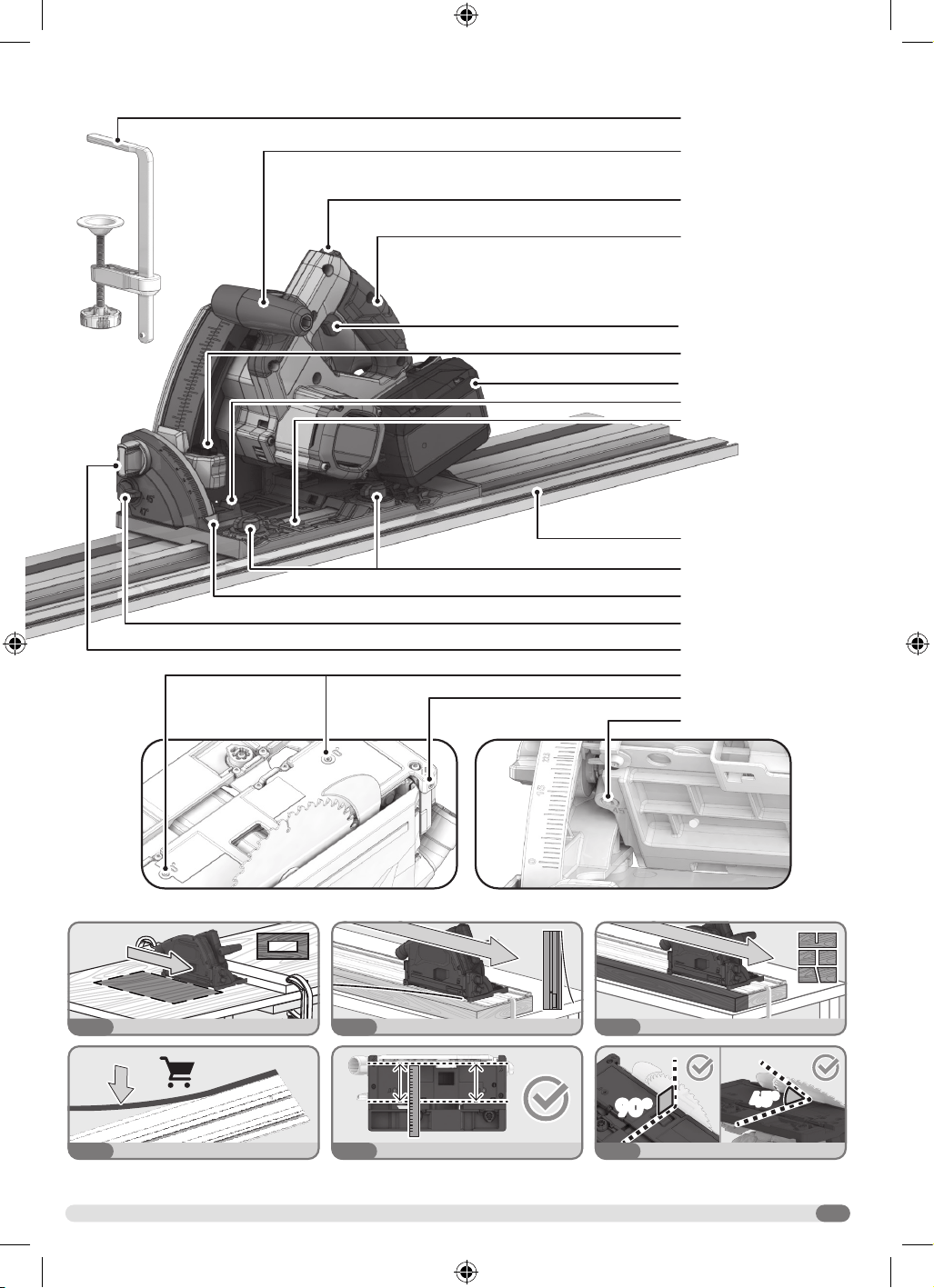
Anti-tip slider
Parallel set screw
45° bevel setting screw
Switch trigger
Battery pack
Dust port
Riving knife
Plunge control lever
Bevel lock knob
Saw blade
Blade screw
Outer blade washer
Wrench
Spindle lock
3
90º90º
45º45º
p. 14
p. 17 p. 18
p. 10
p. 7
p. 7 p. 8
p. 6 p. 6
p. 4
p. 5
p. 16
p. 11 p. 12
Front handle, insulated
gripping surface
Bevel 45º bypass lever
Track adjustment knob
Bevel indicator
0° bevel setting screw
Lock-o button
Track clamp
Depth of cut button
Negative 1º bypass slider
Handle, insulated
gripping surface
Track
Anti-tip slider
Parallel set screw
45° bevel setting screw
Switch trigger
Battery pack
Dust port
Riving knife
Plunge control lever
Bevel lock knob
Saw blade
Blade screw
Outer blade washer
Wrench
Spindle lock
4
1
2
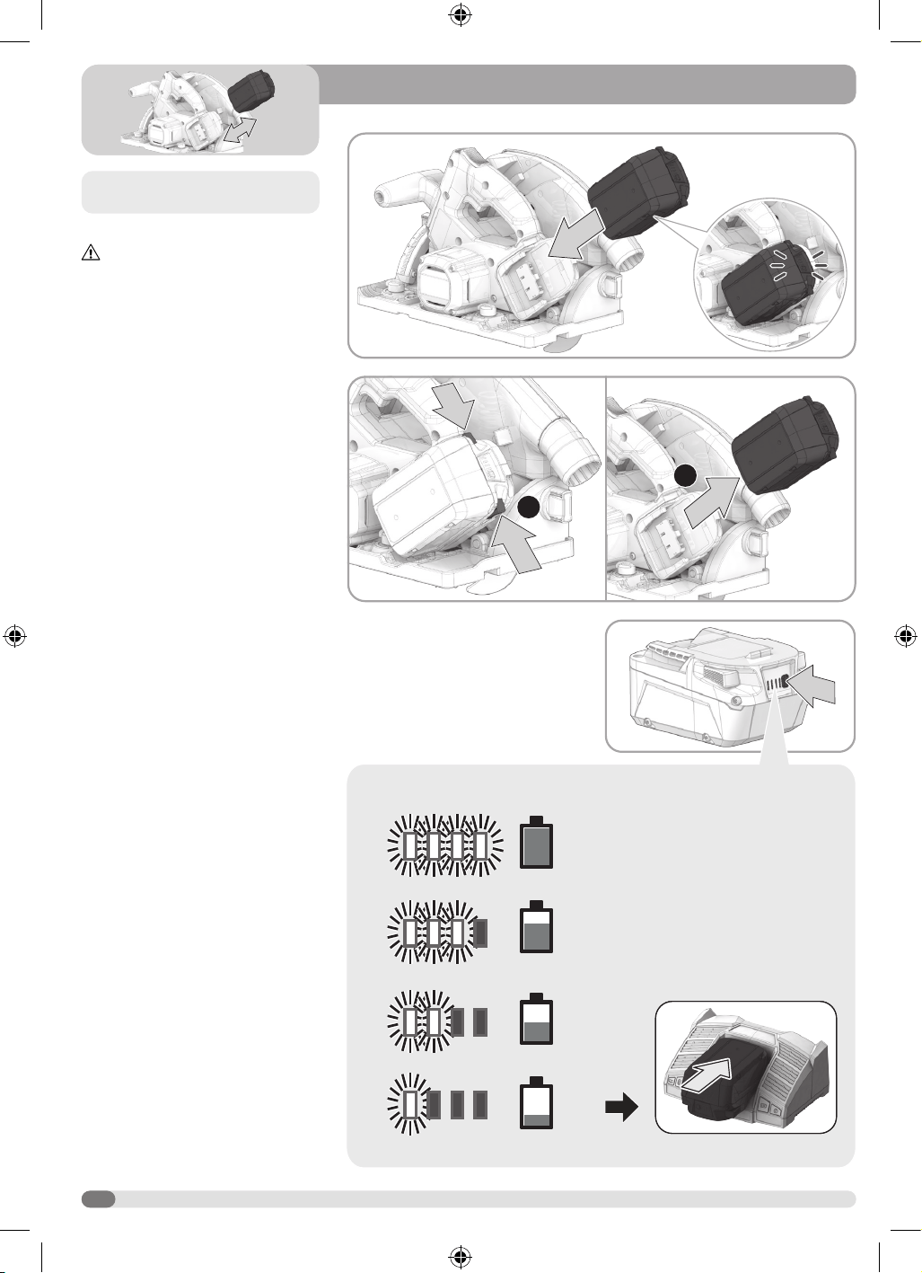
75-100 %
50-75 %
25-50 %
0-25 %
Remove the battery pack before starting any
work on the product.
INSTALLING THE BATTERY PACK
WARNING! Remove the battery pack
and wear safety gloves.
1. Insert the battery pack into the
product.
2. Make sure that the latches on each
side of the battery pack snap in place
and that the battery pack is secured
in the product.
For complete charging instructions, see
the operator’s manuals for your battery
pack and charger.
5
2
2
3
2
1
3
4 5
6
3
1
2
7
1
1
2
1
2
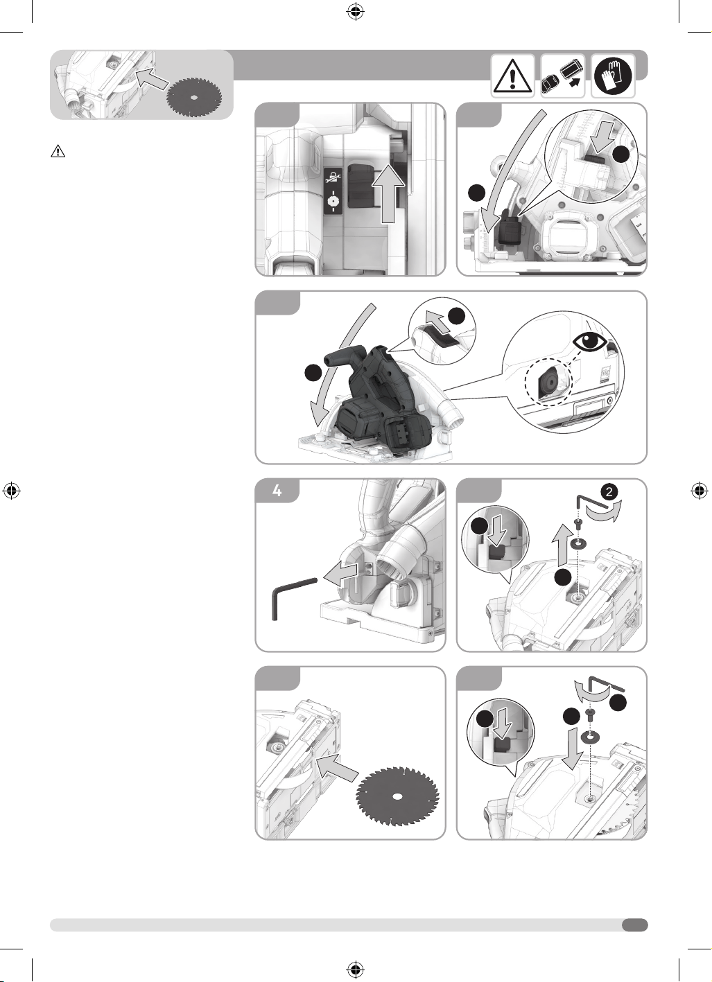
INSTALLING THE BLADE
WARNING! Remove the battery pack
and wear safety gloves.
1. Move the plunge control lever to the
blade change position.
2. Depress the depth of cut button.
Move the depth of cut lever to the
lowest position.
3. Slide the lock-off switch. Lower
the saw to expose the blade screw
through the window in the guard.
4. Remove the blade wrench from the
saw.
5. Depress the spindle lock and
loosen the blade screw by turning
it counterclockwise using the blade
wrench. Remove the blade screw and
outer blade washer.
6. Wear safety gloves. Carefully insert
the blade into the guard. Observe
the correct blade teeth direction. The
rotation direction on the blade should
match the one on the guard. Fit the
blade onto the spindle.
7. Place the outer blade washer
and blade screw onto the spindle.
Depress and hold the spindle lock.
Tighten the blade screw securely by
turning it clockwise.
6
1
1
2
<6 mm<6 mm
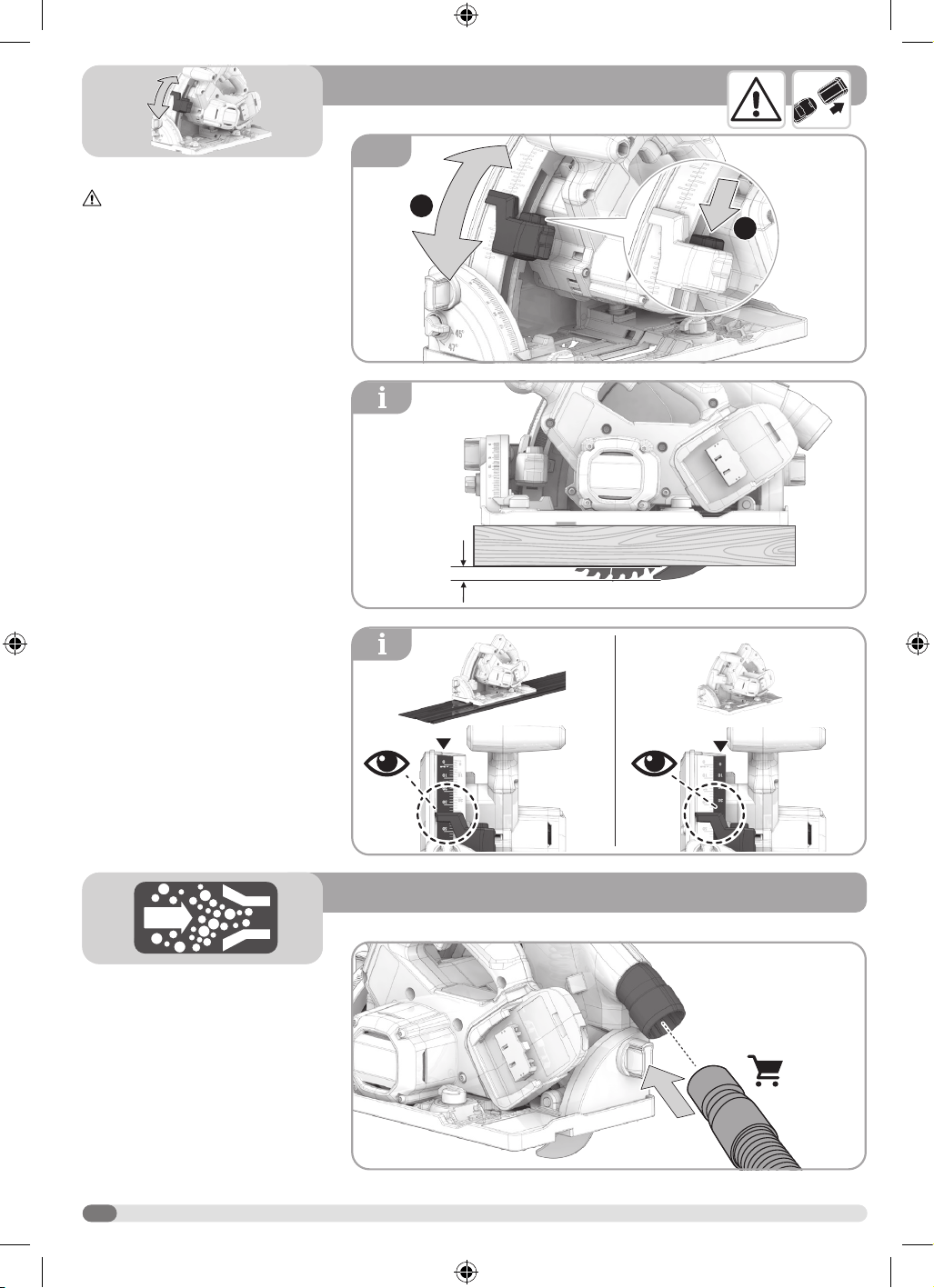
ADJUSTING THE DEPTH OF CUT
WARNING! Remove the battery
pack.
1. Depress the depth of cut button.
Move the depth of cut lever up or
down to adjust the depth of cut.
NOTE: The correct blade depth setting
for all cuts should not exceed 6 mm
below the material being cut.
NOTE: The saw has two depth of cut
indicators. Read the corresponding scale
when using the saw with or without the
track.
DUST PORT CONNECTION
Attach a vacuum hose to the dust port on
the saw for dust extraction.
7
2
2
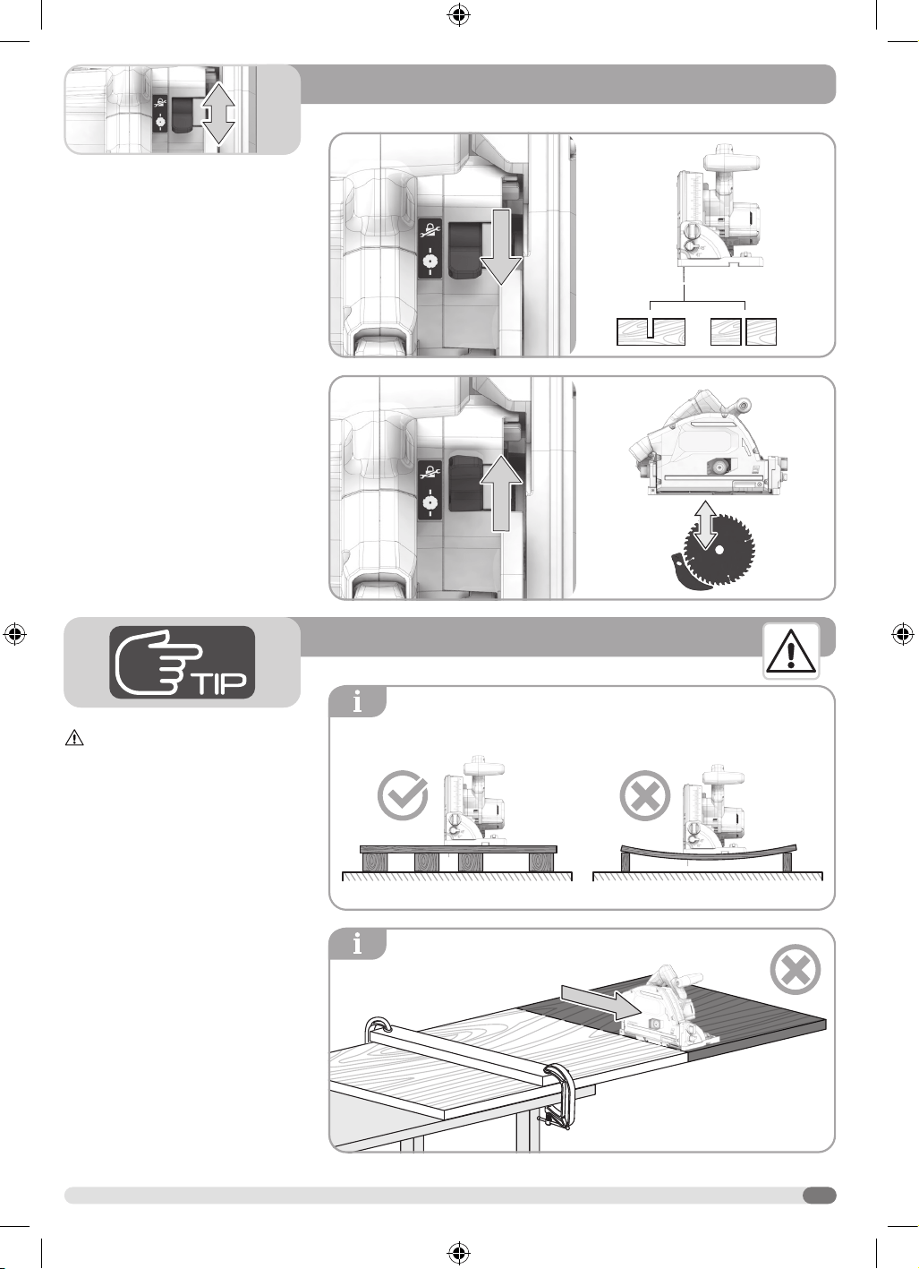
USING THE PLUNGE CONTROL
LEVER
Plunge cut position:
Move the plunge control lever to the
plunge cut position to make deep cuts
and through cuts. When the lever is in
this position, the blade can be lowered to
the full depth of cut.
Blade change position:
Move the plunge control lever to the
blade change position to lock the saw in
a lowered position with the blade screw
visible through the window in the guard.
WARNING!
Support the workpiece properly before
beginning a cut.
Support the workpiece near the cut.
8
2
1
2
3
4
1
2
<6 mm<6 mm
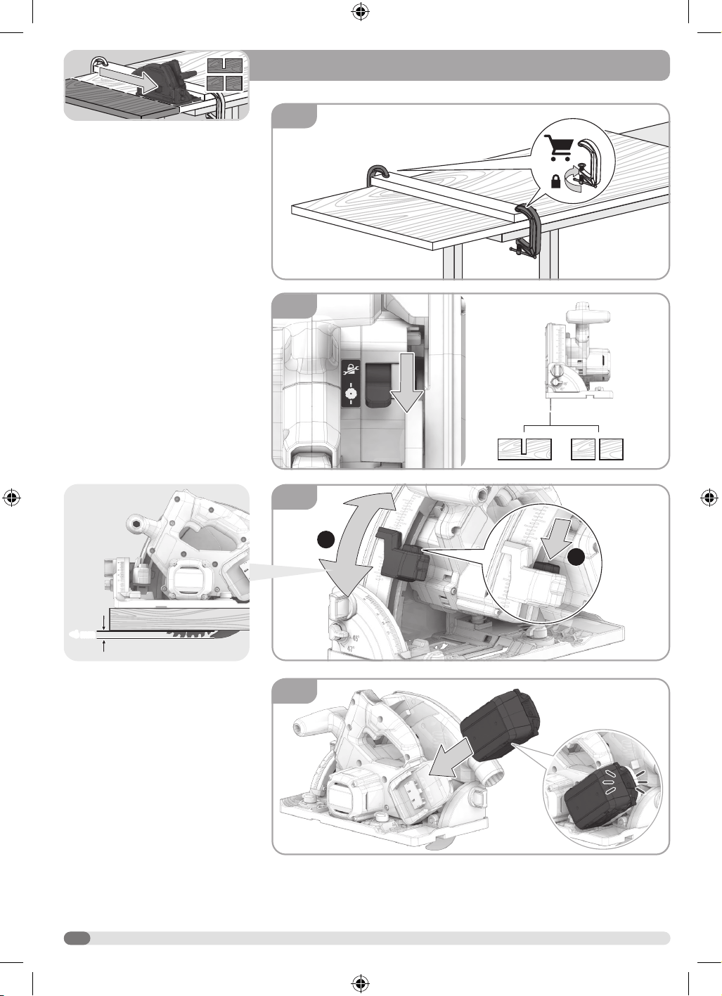
CROSS CUTTING / RIP CUTTING
1. Secure the workpiece to a
workbench, table or other suitable
support. Clamp the workpiece using
C-clamps.
2. Move the plunge control lever to the
plunge cut position.
3. Depress the depth of cut button.
Move the depth of cut lever to the
desired depth of cut.
NOTE: The correct blade depth setting
for all cuts should not exceed 6 mm
below the material being cut.
4. Install the battery pack.
9
5
7
6
1
2
3
8
1
3
5s
2
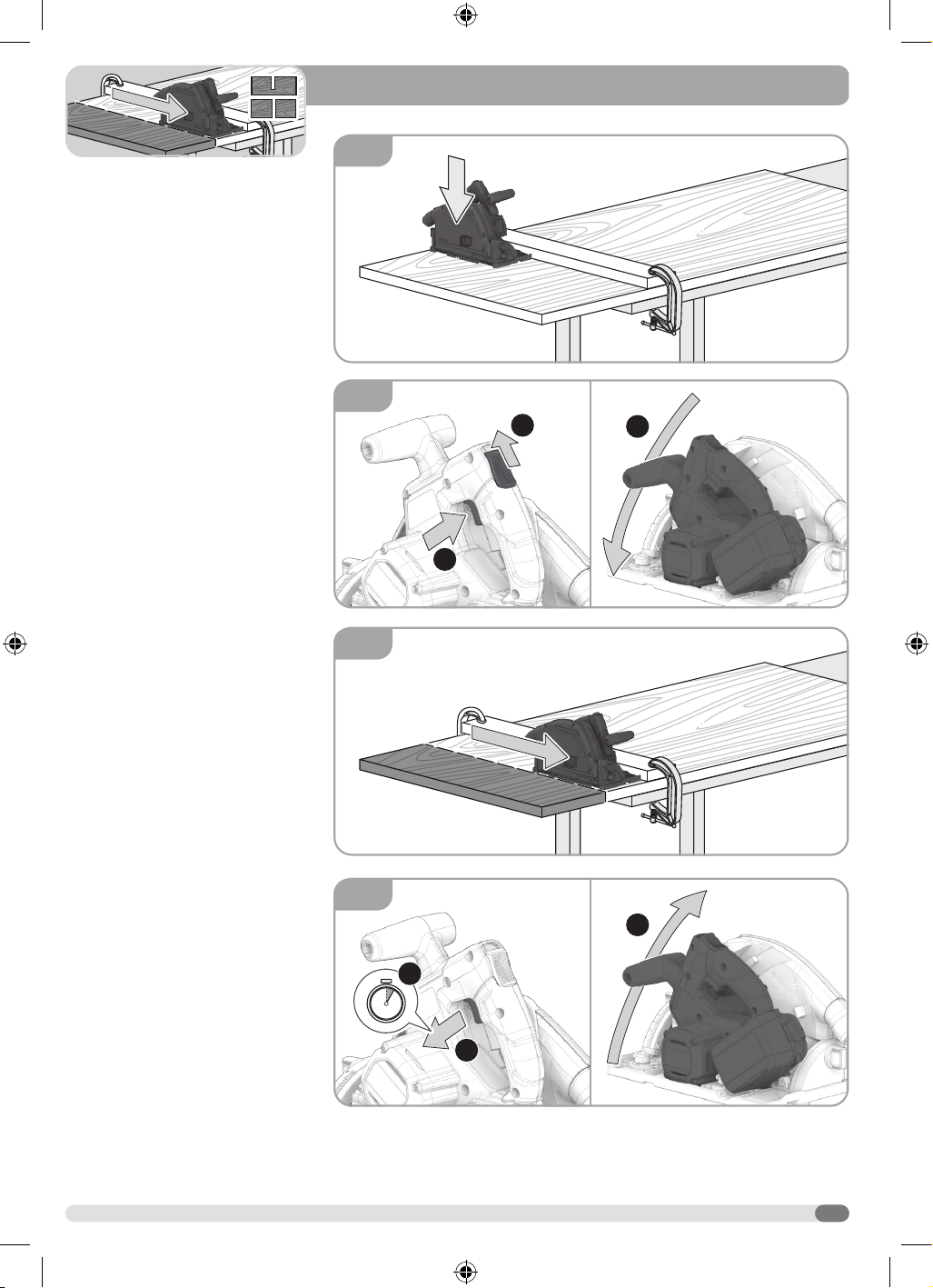
5. Place the saw base flat on the
workpiece.
6. Slide the lock-off switch. Then
depress the switch trigger. Let the
blade reach full speed. Carefully
lower the blade to cut the workpiece.
7. Saw along the straight edge in a
forward direction to achieve a straight
cut.
8. Release the trigger and allow the
blade to come to a complete stop.
Slowly allow the front handle to rise
until the blade is completely inside
of the guard and the saw is in the
locked position.
10
-1º - 47º-1º - 47º
1
2
1
2
0º - 45º0º - 45º
1
3
2
0º - 47º0º - 47º
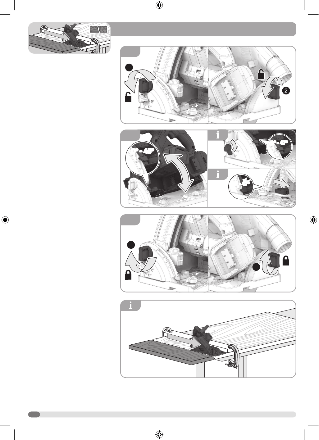
BEVEL CUTTING
1. Loosen the bevel lock knobs.
2. Hold the saw base in place. Move
the saw to the desired bevel angle
up to 45°.
NOTE: Use the bevel 45º bypass lever to
achieve bevel angles between 0 and 47°.
NOTE: Use the negative 1º bypass slider
to achieve a bevel angle of -1°.
3. Tighten the bevel lock knobs.
NOTE: Saw along the straight edge in a
forward direction to achieve a straight cut.
11
1
2
1
2
1
2
1
3
2
0º0º
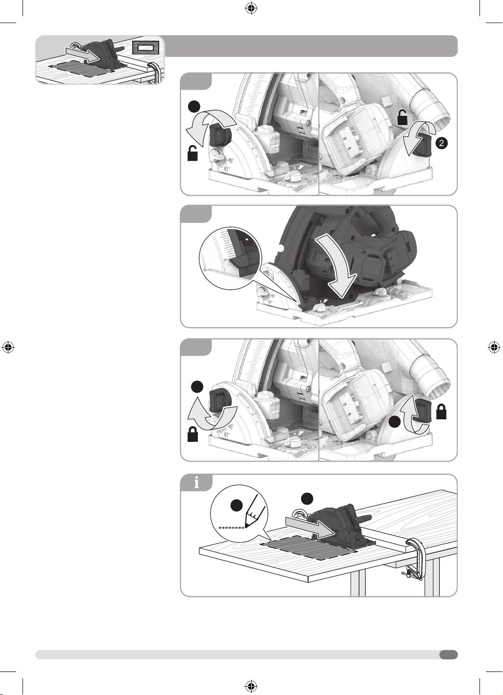
POCKET CUTTING
1. Loosen the bevel lock knobs.
2. Hold the saw base in place. Move the
saw to the 0° position.
3. Tighten the bevel lock knobs.
NOTE: Before cutting, secure the
workpiece to a workbench, table or other
suitable support. Clamp the workpiece
using C-clamps. Draw the cutting line on
the workpiece. Saw along the straight
edge in a forward direction to achieve a
straight cut on each side.
12
1
2
1
2
1
1
2
3
4
2
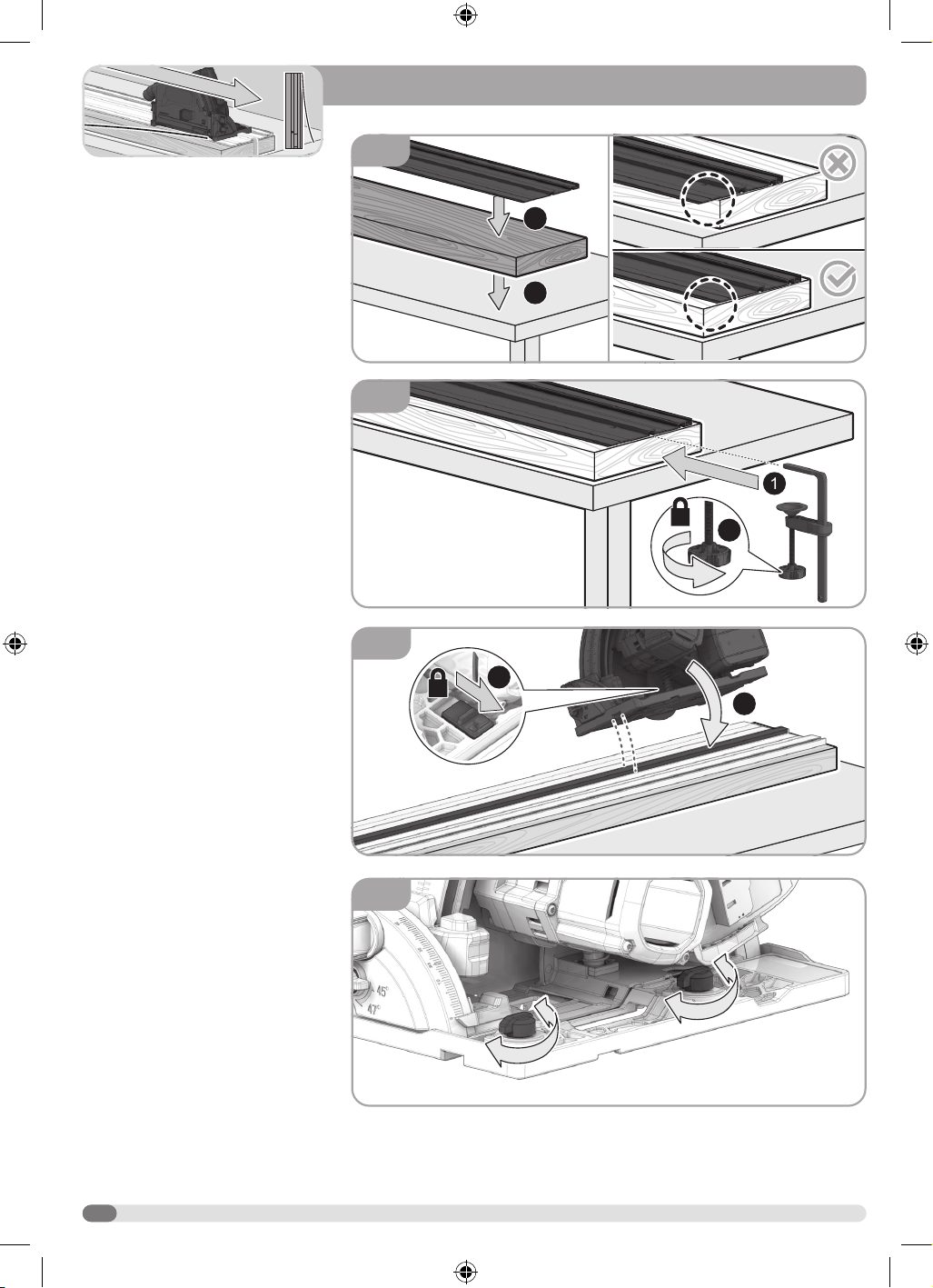
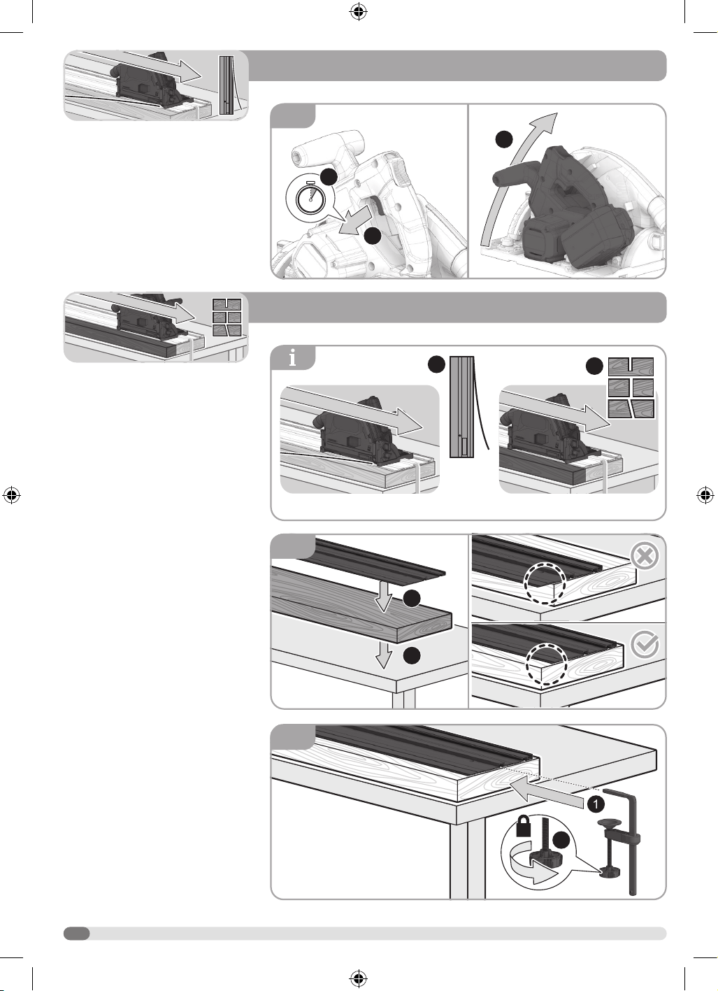
PREPARING THE TRACK FOR USE
1. Place scrap material on a workbench,
table or other suitable support. The
material should be as long or longer
and wider than the track being
prepared for use. Place the track on
the scrap material.
2. Use the track clamp to secure the
track and scrap material to the
support.
3. Hold the saw above the track with the
blade facing the rubber cut strip. Align
the slot in the saw’s base with the
raised tab on the track. Then, lower
the saw onto the track. Slide the anti-
tip slider to extend the tab and secure
the saw on the track.
4. Rotate the track adjustment knobs
until all play (left and right) is
eliminated and the saw moves freely
(forward and back).
13
7
1
3
2
5
6
8
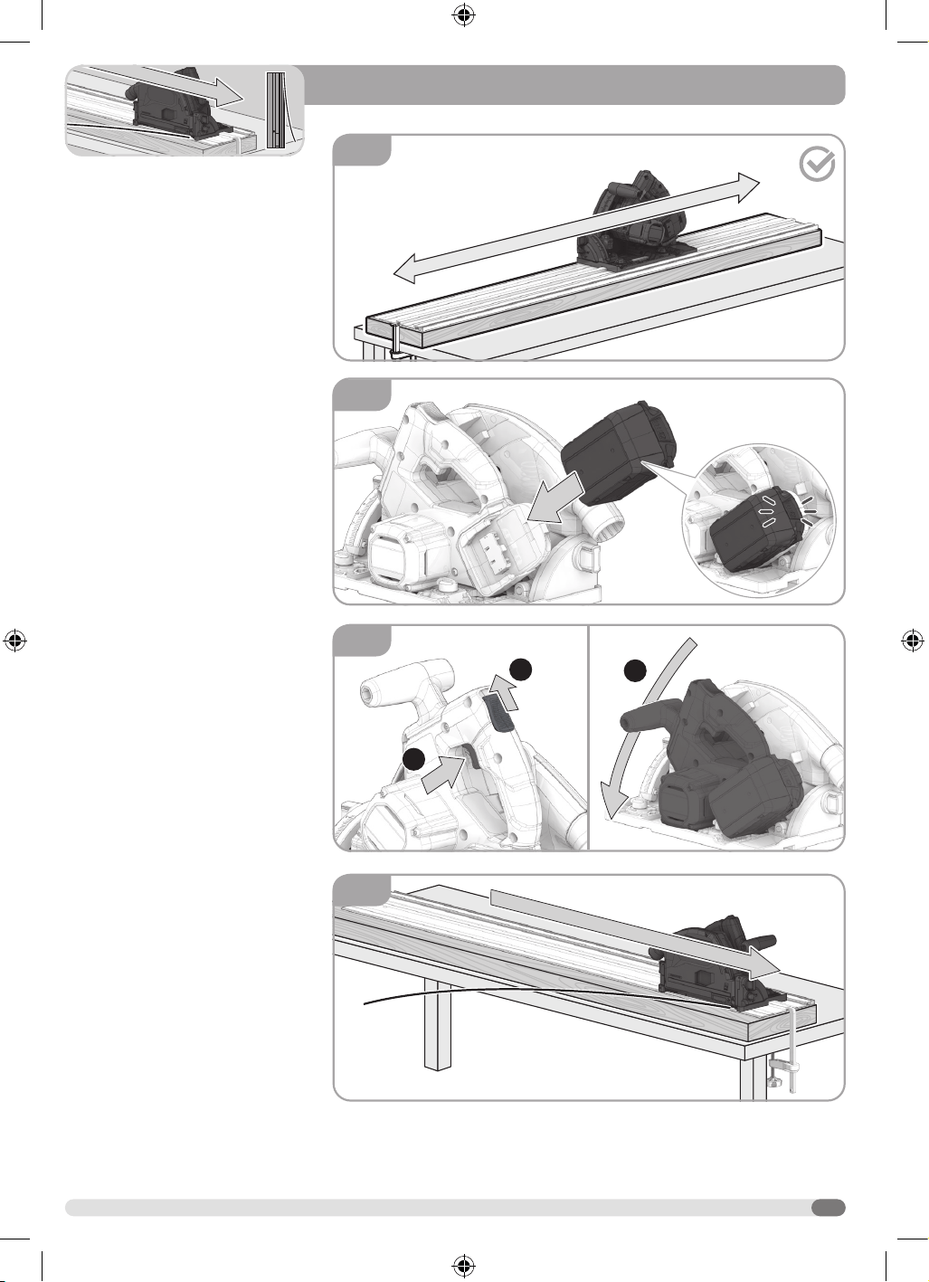
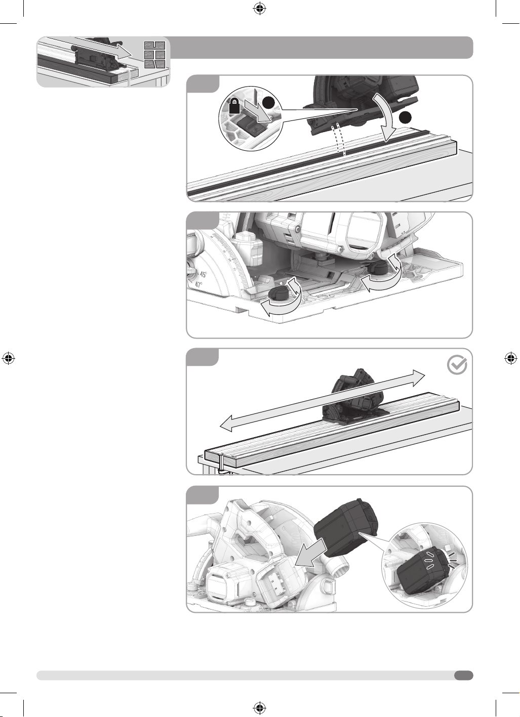
5. Make sure that the saw moves freely
(forward and back).
6. Install the battery pack.
7. Slide the lock-off switch. Then
depress the switch trigger. Let the
blade reach full speed. Carefully
lower the blade to trim the rubber
cut strip.
8. Guide the saw in a forward direction
along the track to trim the rubber
cut strip.
14
9
1
3
5s
2
1
2
1
1
2
2
1
2
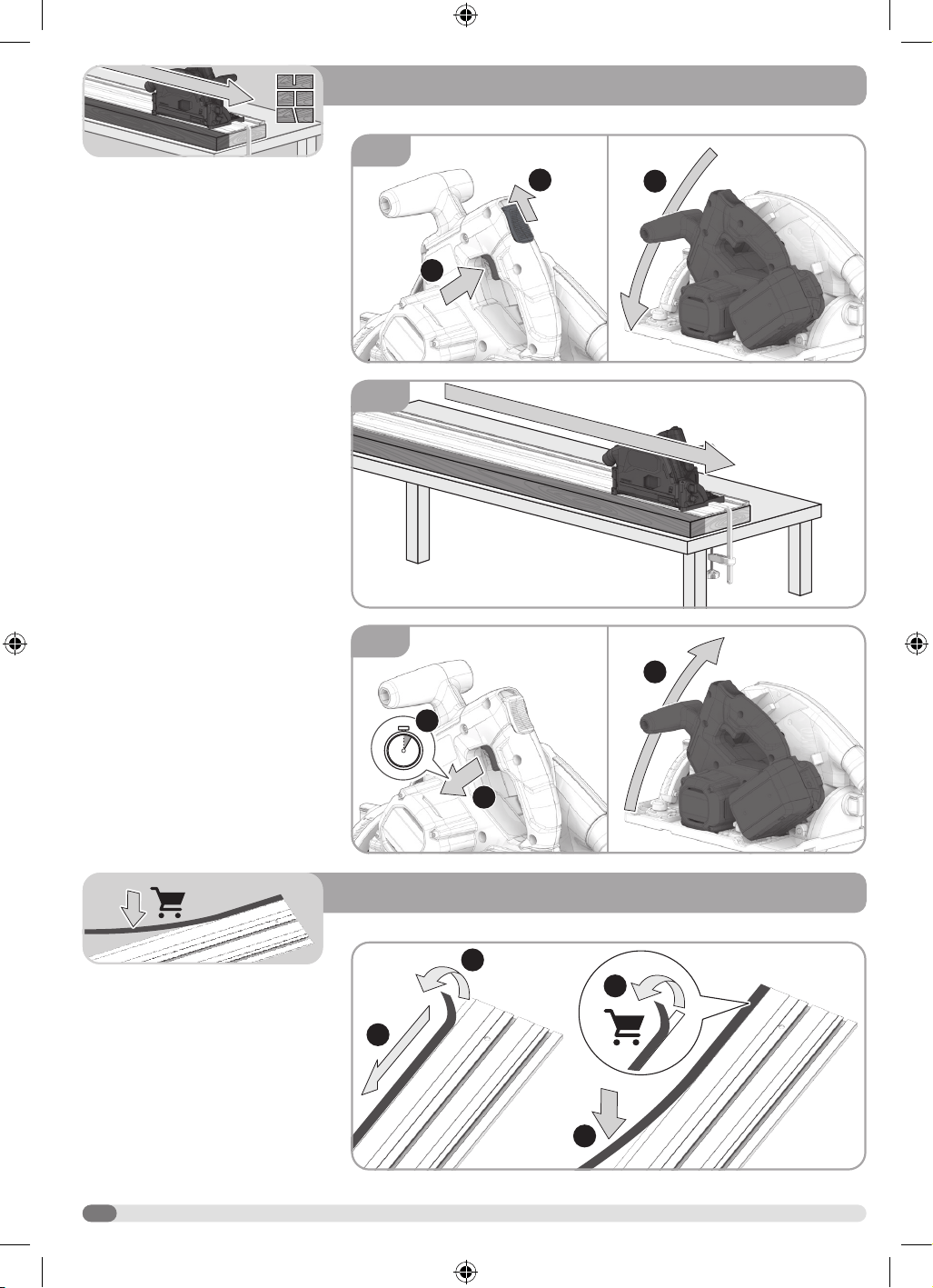
9. Release the trigger and allow the
blade to come to a complete stop.
Slowly allow the front handle to rise
until the blade is completely inside
of the guard and the saw is in the
locked position.
CUTTING ALONG A TRACK
NOTE: Before cutting a workpiece using
the track, the rubber cut strip must be
trimmed away.
1. Place the workpiece on a workbench,
table or other suitable support.
Place the track on the workpiece.
The workpiece should be as long or
longer and wider than the track.
2. Use the track clamp to secure the
track and workpiece to the support.
15
4
6
5
1
3
2
3. Hold the saw above the track with the
blade facing the rubber cut strip. Align
the slot in the saw’s base with the
raised tab on the track. Then, lower
the saw onto the track. Slide the anti-
tip slider to extend the tab and secure
the saw on the track.
4. Rotate the track adjustment knobs
until all play (left and right) is
eliminated and the saw moves freely
(forward and back).
5. Make sure that the saw moves freely
(forward and back).
6. Install the battery pack.
16
1
2
3
4
3
1
5s
2
1
3
2
8
7
9
7. Slide the lock-off switch. Then
depress the switch trigger. Let the
blade reach full speed. Carefully
lower the blade to cut the workpiece.
8. Guide the saw in a forward direction
along the track to cut the workpiece.
9. Release the trigger and allow the
blade to come to a complete stop.
Slowly allow the front handle to rise
until the blade is completely inside
of the guard and the saw is in the
locked position.
REPLACING THE RUBBER STRIP
1. Peel o the rubber strip on the track.
2. Remove the outer film on the new
rubber strip. Apply the rubber strip on
the track.
17
2
3
2
3
4
1
1
1
2
3
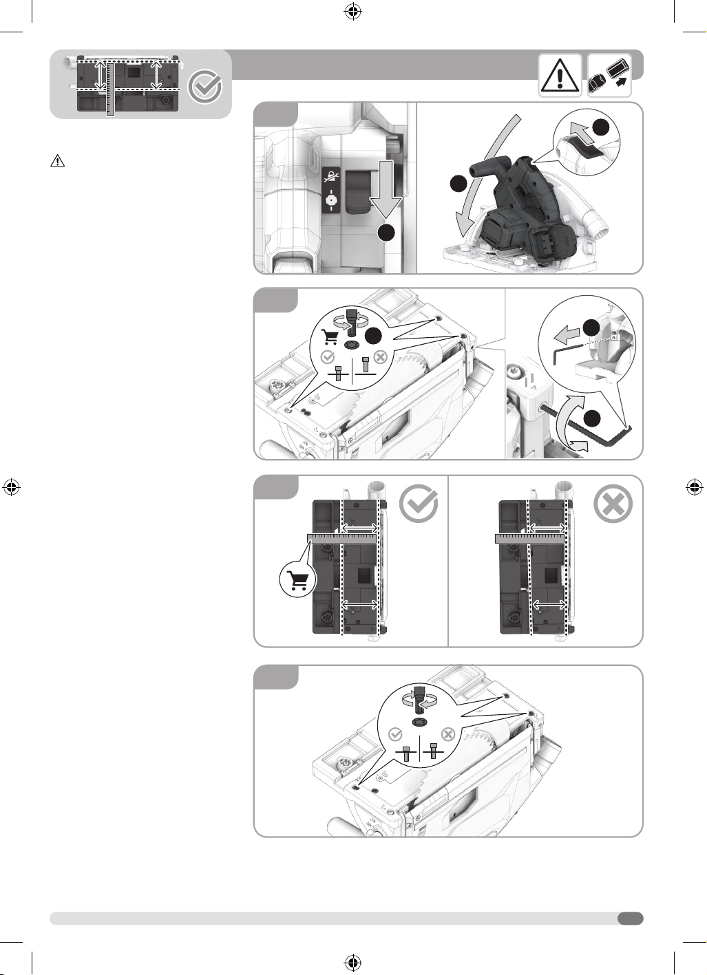
ADJUSTING THE BASE PARALLEL TO
THE TO THE BLADE
WARNING! Remove the battery
pack.
1. Move the plunge control lever to the
plunge cut position. Slide the lock-off
Carefully lower the blade.
2. Turn the saw upside down. Loosen
but do not remove the screws near
the front and back of the base.
Remove the blade wrench from the
saw. Turn the parallel set screw to
adjust the base.
3. Using a ruler, measure the distance
from one of the blade teeth at the
front to the edge of the saw base slot.
Move the ruler to the rear. Measure
the distance from one of the blade
teeth at the rear to the edge of the
saw base slot. Adjust the base until
both measurements are the same.
4. Tighten the screws.
18
90º90º
45º45º
1
2
2
3
0º0º
1
4
2
2
3
1
1
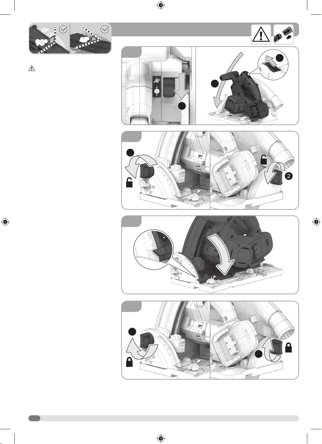
SETTING THE BLADE AT 0° AND 45°
WARNING! Remove the battery
pack.
1. Move the plunge control lever to the
plunge cut position. Slide the lock-off
Carefully lower the blade.
2. Loosen the bevel lock knobs.
3. Hold the saw base in place. Move the
saw to the 0° bevel angle.
4. Tighten the bevel lock knobs.
19
90º90º
45º45º
45º45º
0º0º
0º0º
1
2
6
7
8
5
1
2
2
1
3
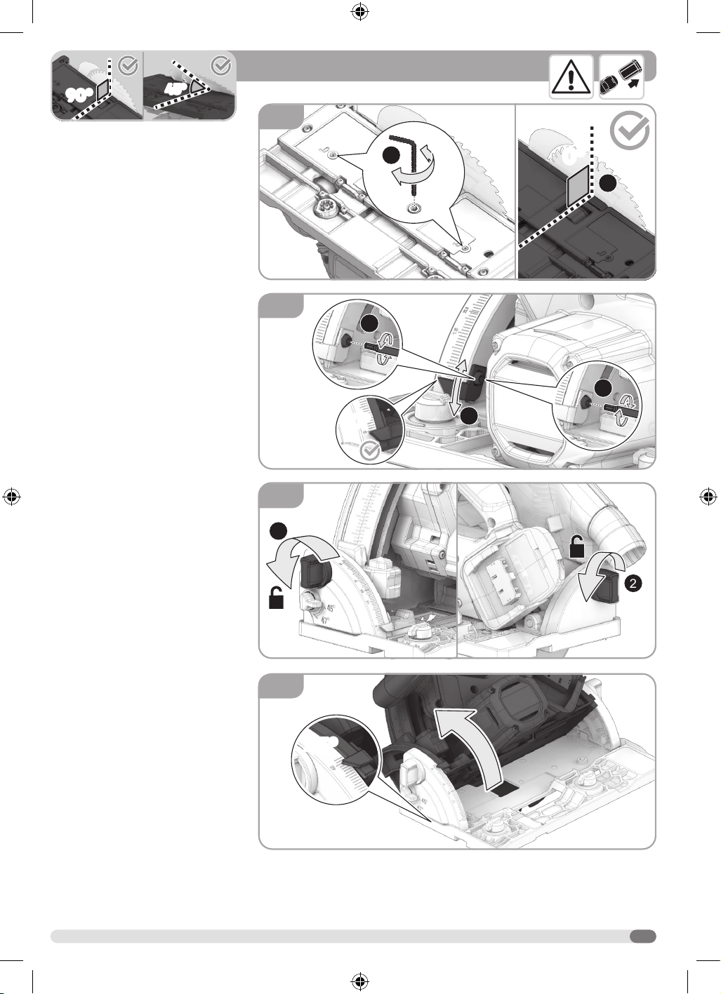
5. Using the blade wrench, turn the 0°
bevel setting screws to adjust the
blade. Verify that the saw blade is
90° to the base of the saw using a
combination square
6. Check the bevel indicator. If the
indicator is not pointing to the 0º
mark on the bevel scale, loosen the
indicator adjusting screw and adjust
the indicator. Tighten the screw.
7. Loosen the bevel lock knobs.
8. Hold the saw base in place. Move the
saw to the 45° bevel angle.
20
90º90º
45º45º
45º45º
1
2
1
9
2
10
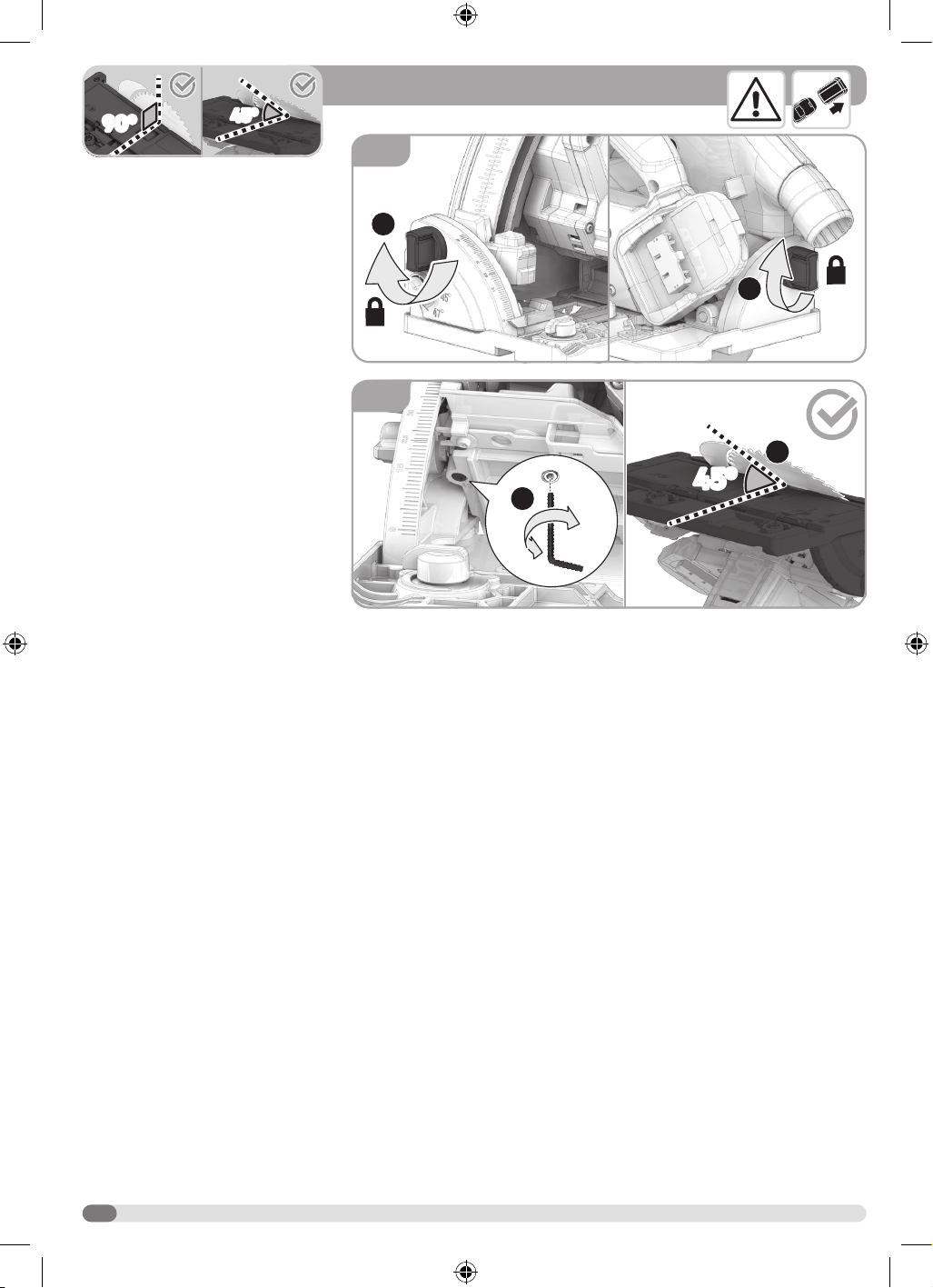
9. Tighten the bevel lock knobs.
10. Using the blade wrench, turn the
45° bevel setting screw to adjust
the blade. Verify that the saw blade
is 45° to the base of the saw using
a combination square. Readjust if
needed.
21
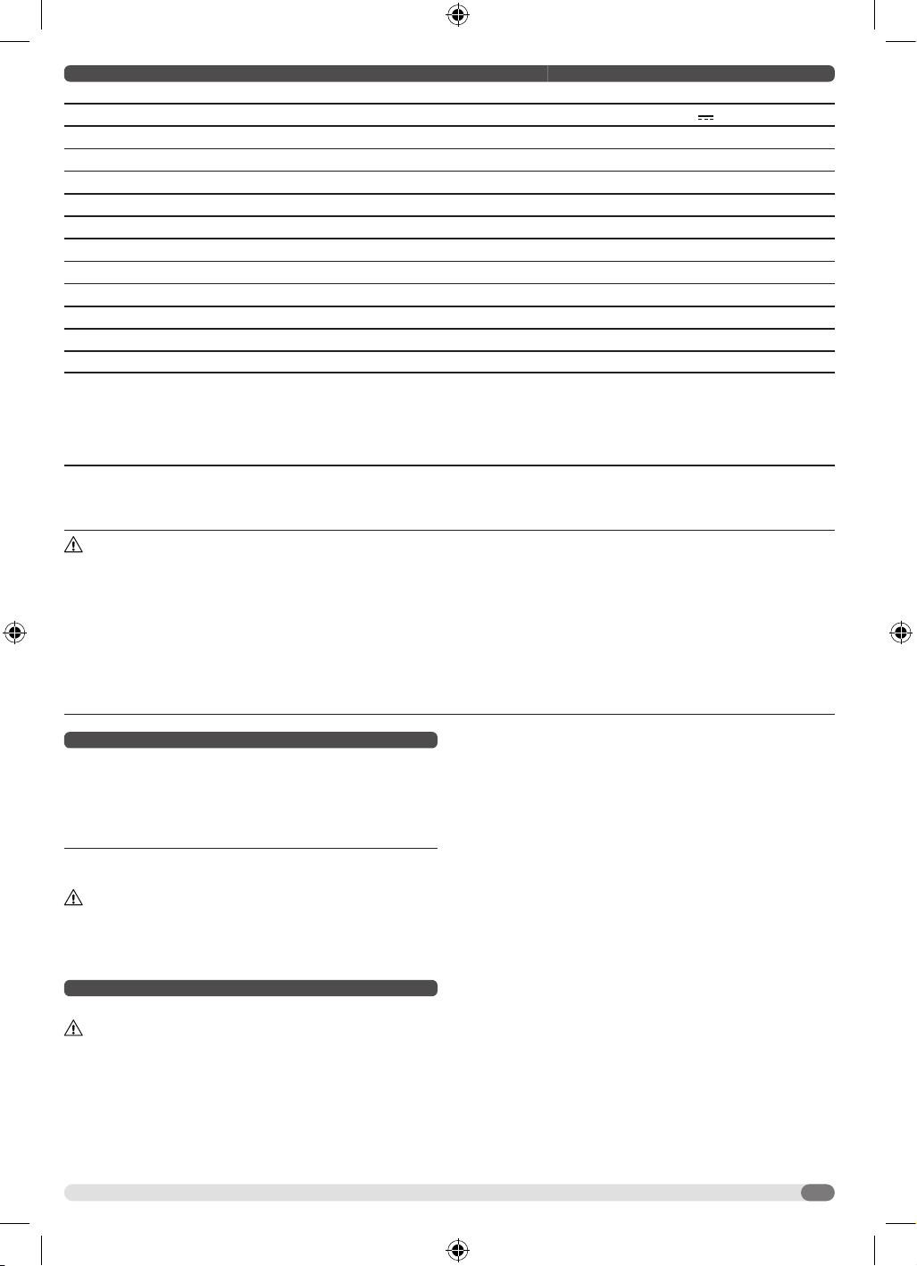
TECHNICAL DATA A18FTSB0
Type Track saw
Battery voltage 18 V
No-load speed 5000 min
-1
Saw blade diameter x hole diameter 165 x 20 mm
Saw blade thickness / tooth thickness
1.3 / 2.0 mm
Blade teeth 40T
Max. cutting depth at 0°
With track 54.0 mm
Without track 58.5 mm
Max. cutting depth at 45°
With track
38.1 mm
Without track 42.5 mm
Weight without battery pack 4.0 kg
Noise Information
Measured values determined according to EN 62841. Typically, the A-weighted noise
levels of the tool are:
Sound pressure level / Uncertainty
Sound power level / Uncertainty
Wear ear protection!
L
pA
=92 dB (A) / K
pA
=3 dB(A)
L
WA
=100 dB (A) / K
WA
=3 dB(A)
Vibration Information
Vibration total values (triaxial vector sum) determined according to EN 62841.
Vibration emission value / Uncertainty
Cutting wood a
h,B
=1.7 m/s
2
/ K=1.5 m/s
2
WARNING!
The declared vibration total values and the declared noise emission values given in this instruction manual have been measured in
accordance with a standardised test and may be used to compare one tool with another. They may be used for a preliminary assessment
of exposure.
The declared vibration and noise emission values represent the main applications of the tool. However, if the tool is used for dierent
applications, used with dierent accessories, or poorly maintained, the vibration and noise emission may dier. These conditions may
signicantly increase the exposure levels over the total working period.
An estimation of the level of exposure to vibration and noise should take into account the times when the tool is turned o or when it is
running idle. These conditions may signicantly reduce the exposure level over the total working period.
Identify additional safety measures to protect the operator from the eects of vibration and noise, such as maintaining the tool and the
accessories, keeping the hands warm (in case of vibration), and organising work patterns.
COMPATIBLE BATTERY PACKS (NOT INCLUDED)
L1820R
L1820S
A18FB2
L1825R
L1830R-X5
A18B4
L1840R
A18FB4
L1850R
A18FB5
A18OB6
L1860R
L1860R-X5
L1890R
Use AEG 18V battery and charger only
WARNING! Read all safety warnings, instructions,
illustrations and specications provided with this power tool.
Failure to follow all instructions listed below may result in electric
shock, re and/or serious injury.
Save all warnings and instructions for future reference.
TRACK SAW SAFETY WARNINGS
Cutting procedures
DANGER: Keep hands away from cutting area and the blade.
Keep your second hand on auxiliary handle, or motor housing. If
both hands are holding the saw, they cannot be cut by the blade.
Do not reach underneath the workpiece. The guard cannot protect
you from the blade below the workpiece.
Adjust the cutting depth to the thickness of the workpiece.
Less than a full tooth of the blade teeth should be visible below the
workpiece.
Never hold the workpiece in your hands or across your leg
while cutting. Secure the workpiece to a stable platform. It is
important to support the work properly to minimise body exposure,
blade binding, or loss of control.
Hold the power tool by insulated gripping surfaces, when
performing an operation where the cutting tool may contact
hidden wiring. Contact with a “live” wire will also make exposed
metal parts of the power tool “live” and could give the operator an
electric shock.
When ripping, always use a rip fence or straight edge guide.
This improves the accuracy of cut and reduces the chance of blade
binding.
Always use blades with correct size and shape (diamond
versus round) of arbour holes. Blades that do not match the
mounting hardware of the saw will run o-centre, causing loss of
control.
Never use damaged or incorrect blade washers or bolt. The
blade washers and bolt were specially designed for your saw, for
optimum performance and safety of operation.
Kickback causes and related warnings
• kickback is a sudden reaction to a pinched, jammed or
misaligned saw blade, causing an uncontrolled saw to lift up and
out of the workpiece toward the operator;
• when the blade is pinched or jammed tightly by the kerf closing
down, the blade stalls and the motor reaction drives the unit
rapidly back toward the operator;
• if the blade becomes twisted or misaligned in the cut, the teeth
at the back edge of the blade can dig into the top surface of the
22
wood causing the blade to climb out of the kerf and jump back
toward the operator.
Kickback is the result of saw misuse and/or incorrect operating
procedures or conditions and can be avoided by taking proper
precautions as given below.
Maintain a rm grip with both hands on the saw and position
your arms to resist kickback forces. Position your body to
either side of the blade, but not in line with the blade. Kickback
could cause the saw to jump backwards, but kickback forces can
be controlled by the operator, if proper precautions are taken.
When blade is binding, or when interrupting a cut for any
reason, release the trigger and hold the saw motionless in
the material until the blade comes to a complete stop. Never
attempt to remove the saw from the work or pull the saw
backward while the blade is in motion or kickback may occur.
Investigate and take corrective actions to eliminate the cause of
blade binding.
When restarting a saw in the workpiece, centre the saw blade
in the kerf so that the saw teeth are not engaged into the
material. If a saw blade binds, it may walk up or kickback from the
workpiece as the saw is restarted.
Support large panels to minimise the risk of blade pinching
and kickback. Large panels tend to sag under their own weight.
Supports must be placed under the panel on both sides, near the
line of cut and near the edge of the panel.
Do not use dull or damaged blades. Unsharpened or improperly
set blades produce narrow kerf causing excessive friction, blade
binding and kickback.
Blade depth and bevel adjusting locking levers must be tight
and secure before making the cut. If blade adjustment shifts
while cutting, it may cause binding and kickback.
Use extra caution when sawing into existing walls or other
blind areas. The protruding blade may cut objects that can cause
kickback.
Guard function
Check the guard for proper closing before each use. Do not
operate the saw if the guard does not move freely and enclose
the blade instantly. Never clamp or tie the guard so that the
blade is exposed. If the saw is accidentally dropped, the guard
may be bent. Check to make sure that the guard moves freely and
does not touch the blade or any other part, in all angles and depths
of cut.
Check the operation and condition of the guard return spring.
If the guard and the spring are not operating properly, they
must be serviced before use. The guard may operate sluggishly
due to damaged parts, gummy deposits, or a build-up of debris.
Assure that the base plate of the saw will not shift while
performing a “plunge cut”. Blade shifting sideways will cause
binding and likely kick back.
Always observe that the guard is covering the blade before
placing the saw down on bench or oor. An unprotected,
coasting blade will cause the saw to walk backwards, cutting
whatever is in its path. Be aware of the time it takes for the blade to
stop after the switch is released.
Riving knife function
Use the appropriate saw blade for the riving knife. For the riving
knife to function, the body of the blade must be thinner than the
riving knife and the cutting width of the blade must be wider than
the thickness of the riving knife.
Adjust the riving knife as described in this instruction manual.
Incorrect spacing, positioning and alignment can make the riving
knife ineective in preventing kickback.
For the riving knife to work, it must be engaged in the
workpiece. The riving knife is ineective in preventing kickback
during short cuts.
Do not operate the saw if the riving knife is bent. Even a light
interference can slow the closing rate of a guard.
ADDITIONAL SAFETY AND WORKING INSTRUCTIONS
Do not use any abrasive wheels.
Ensure that the riving knife is adjusted so that the distance between
the riving knife and the rim of the blade is not more than 5 mm, and
the rim of the blade does not extend more than 5 mm beyond the
lowest edge of the riving knife.
Use only blade diameter(s) in accordance with the markings.
Identify the correct saw blade to be used for the material to be cut.
Use only saw blades that are marked with a speed equal or higher
than the speed marked on the tool.
Use only saw blades recommended by the manufacturer, which
conform to EN 847-1, if intended for wood and analogous
materials.
Wear a dust mask.
Clamp the workpiece with a clamping device. Unclamped
workpieces can cause severe injury and damage.
Dirty blade guards may limit proper operation of the product,
resulting in serious personal injury. Clean the blade guards with
compressed air to ensure there is no accumulation of saw dust.
Wear proper eye and respiratory protection.
Check and make sure that the blade guard functions properly.
Follow the steps below to check the proper function of the blade
guard.
• Ensure that the battery is removed from the product.
• Press the lock-off button.
• Grasp the front handle and apply downward pressure to lower
and expose the blade.
• Slowly allow the front handle to rise until the blade is completely
inside of the guard.
• Make sure that the blade guard fully encloses the blade.
• If the guard and the spring are not operating properly, they must
be serviced before use.
Turn o the product immediately if it stalls. Do not switch on the
product again after it has stalled. Switching it on again can cause a
kickback with high reaction force. Determine why the product has
stalled and rectify it, paying heed to the safety instructions.
Remove the battery pack before starting any work on the product.
SPECIFIED CONDITIONS OF USE
The track saw is intended for rip-cutting and cross-cutting of
wood or similar materials up to a maximum depth of 58.5 mm.
The product can make straight or bevelled cuts between 0 and 45
degrees.
The product is designed for handheld use. The product is not to
be mounted onto a workbench. Do not use the product for cutting
metal or masonry.
Do not use the product for any other purpose.
ADDITIONAL BATTERY SAFETY WARNINGS
WARNING! To reduce the risk of re, personal injury, and
product damage due to a short circuit, never immerse your tool,
battery pack, or charger in uid or allow uid to ow inside them.
Corrosive or conductive uids, such as seawater, certain industrial
chemicals, and bleach or bleach containing products, etc., can
cause a short circuit.
Do not dispose of used battery packs in the household refuse or
by burning them. AEG distributors oer to retrieve old batteries to
protect our environment.
Battery packs that have not been used for some time should be
recharged before use.
For an optimum lifetime, the battery packs have to be fully charged
after use.
For battery pack storage longer than 30 days:
• Store the battery pack where the temperature is below 27°C and
away from moisture.
• Store the battery packs in a 30% - 50% charged condition.
• Every six months of storage, charge the pack as normal.
Battery pack protection
The battery pack has overload protection that protects it from being
overloaded and helps to ensure long life.
Under extreme stress, the battery electronics turn o the product
automatically. To restart, turn the product o and then on again.
If the product does not start up again, the battery pack may have
discharged completely. Recharge the battery pack.
23
Transporting lithium batteries
Lithium-ion batteries are subject to the Dangerous Goods
Legislation requirements.
Transportation of those batteries has to be done in accordance
with local, national, and international provisions and regulations.
• Batteries can be transported by road without further requirement.
• Commercial transport of lithium-ion batteries by third parties is
subject to Dangerous Goods regulations. Transport preparation
and transport are exclusively to be carried out by appropriately
trained persons and the process has to be accompanied by
corresponding experts.
When transporting batteries:
• Ensure that the battery contact terminals are protected and
insulated to prevent short circuit.
• Ensure that the battery pack is secured against movement within
the packaging.
• Do not transport batteries that are cracked or leaking.
• Check with the forwarding company for further advice.
MAINTENANCE
Avoid using solvents when cleaning plastic parts. Most plastics
are susceptible to various types of commercial solvents and may
be damaged by their use. Use clean cloths to remove dirt, carbon
dust, etc.
Use only AEG accessories and spare parts. Should components
that have not been described need to be replaced, contact one
of our AEG service agents (see our list of guarantee/service
addresses).
If needed, an exploded view of the product can be ordered. State
the product type and the serial number printed on the label, and
order the drawing at your local service agents or directly at:
Techtronic Industries Australia Pty Ltd
PO Box 1065
Mount Waverley VIC 3149
Tel. no. 1300 234 797
Australia
Techtronic Industries N.Z. Limited
PO Box 12-806
Penrose AUCKLAND 1642
Tel. no. 0800 234 797(0800 AEGPWR)
New Zealand
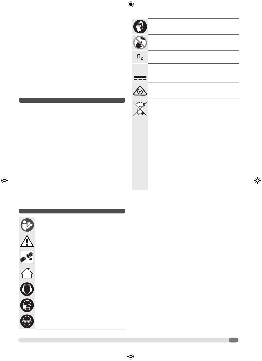
SYMBOLS
Read the instructions carefully before starting the
product.
CAUTION! WARNING! DANGER!
Remove the battery pack before starting any work on
the product.
For indoor use only
Wear ear protectors.
Wear a suitable dust protection mask.
Wear eye protection.
Wear protective gloves.
Keep hands away from the cutting area and sharp
blade.
No-load speed
V
Volts
Direct current
Regulatory Compliance Mark (RCM). Product meets
applicable regulatory requirements.
Do not dispose of waste batteries, waste electrical and
electronic equipment as unsorted municipal waste.
Waste batteries and waste electrical and electronic
equipment must be collected separately.
Waste batteries, waste accumulators, and light sources
have to be removed from the equipment.
Check with your local authority or retailer for recycling
advice and collection point.
According to local regulations, retailers may have an
obligation to take back waste batteries and waste
electrical and electronic equipment free of charge.
Your contribution to the reuse and recycling of waste
batteries and waste electrical and electronic equipment
helps to reduce the demand of raw materials.
Waste batteries, in particular containing lithium, and
waste electrical and electronic equipment contain
valuable and recyclable materials, which can adversely
impact the environment and the human health if not
disposed of in an environmentally compatible manner.
Delete personal data from waste equipment, if any.

Techtronic Industries Australia Pty Ltd
31 Gilby Road, Mount Waverley,
VIC, 3149, Australia
Techtronic Industries N.Z. Limited
Unit C, 70 Business Parade South,
Highbrook, Auckland 2013, New Zealand
www.aegpowertools.com.au
www.aegpowertools.co.nz
961001877-01A
AEG is a registered trade mark used under
license from AB Electrolux (publ).