READ AND SAVE THESE INSTRUCTIONS FOR REFERENCE
46384A
Printed in Canada 2025-02-04
Installation and Operation Manual
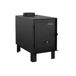
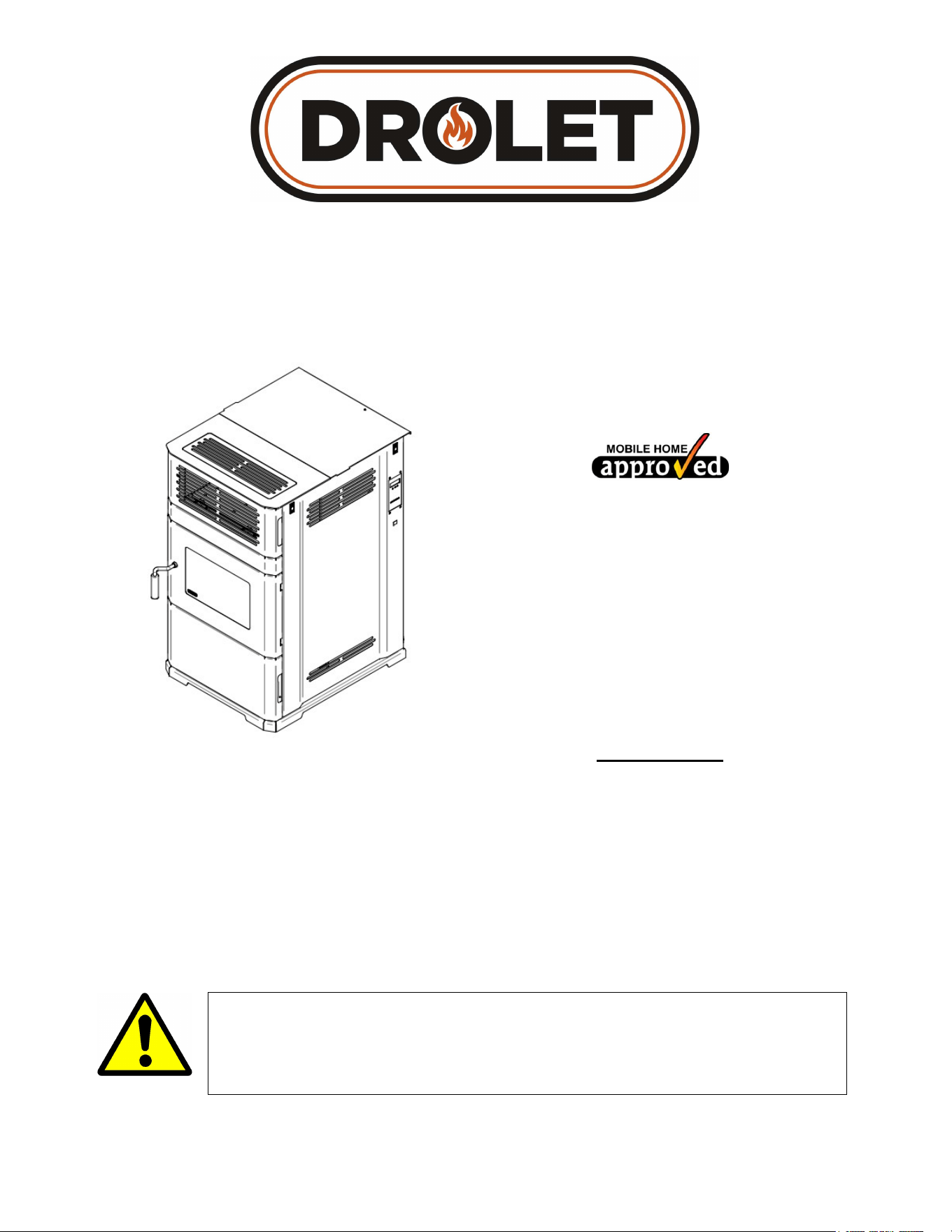
ECO-65R
(DP00061 model)
Safety tested according to ULC S627 and
ASTM E1509 by
an accredited laboratory
US Environmental Protection Agency phase
II certified pellet stove compliant with 2020
standard using pellet fuel
EPA ≤ 2.0 g/h
Fabricant de poêles international inc.
250, rue de Copenhague, St-Augustin-de-
Desmaures (Québec) Canada G3A 2H3
Technical service: 1-877-356-6663
E-mail: tech@sbi-international.com
www.drolet.ca
CONTACT LOCAL BUILDING OR FIRE OFFICIALS ABOUT RESTRICTIONS AND
INSTALLATION INSPECTION REQUIREMENTS IN YOUR AREA.
PLEASE READ THIS ENTIRE MANUAL BEFORE INSTALLATION AND USE OF THIS
PELLET FUEL-BURNING ROOM HEATER. FAILURE TO FOLLOW THESE
INSTRUCTIONS COULD RESULT IN PROPERTY DAMAGE, BODILY INJURY OR EVEN
DEATH.
INSTALLATION BY A PROFESSIONAL IS STRONGLY RECOMMENDED
This manual is available for free download on the manufacturer’s web site. It is a copyrighted
document. Re-sale is strictly prohibited. The manufacturer may update this manual from
time to time and cannot be responsible for problems, injuries, or damages arising out of the
use of information contained in any manual obtained from unauthorized sources.

ECO-65R Installation and Operation Manual
2
THANK YOU FOR CHOOSING THIS DROLET PELLET STOVE
As one of North America’s largest and most respected pellet stove, wood stove and fireplace
manufacturers, Stove Builder International takes pride in the quality and performance of all its
products. We want to help you get maximum satisfaction as you use this product.
In the pages that follow you will find general advice on pellet heating, detailed instructions for
safe and effective installation, and guidance on how to get the best performance from this stove
as you build and maintain your pellet heating system.
We highly recommend that our pellet burning hearth products be installed and serviced by
professionals who are certified in the United States by NFI (National Fireplace Institute
®
) or in
Canada by WETT (Wood Energy Technology Transfer) or in Quebec by APC (Association des
Professionnels du Chauffage).
Congratulations on making a wise purchase.
REGISTER YOUR WARRANTY ONLINE
To receive full warranty coverage, you will need to show
evidence of the date you purchased your stove. Keep your sales
invoice. We also recommend that you register your warranty
online at:
http://www.drolet.ca/en/service-support/warranty-registration
Registering your warranty online will help us to quickly track the
information we need about your stove.

ECO-65R Installation and Operation Manual
3
Table of contents
1 General information ECO-65R (DP00061) ............................................................................................. 5
1.1 About Pellet Heating .............................................................................................................................. 5
1.1.1 Top 10 Reasons for Buying a Pellet Stove ................................................................................... 5
1.2 Appliance performance
(1)
...................................................................................................................... 6
1.3 General Features .................................................................................................................................. 7
1.4 Overall Exterior Dimensions .................................................................................................................. 8
PART A – INSTALLATION ................................................................................................................................ 9
2 Installation Safety Information ............................................................................................................... 9
2.1 Installation Warnings, Cautions and Recommendations ...................................................................... 9
2.2 Regulations Covering Pellet Stove Installation ................................................................................... 11
2.3 Before Operating Your Stove .............................................................................................................. 11
3 Clearances to Combustible Material.................................................................................................... 12
3.1 Certification Label Location ................................................................................................................. 12
3.2 Minimum Clearances to Combustibles ................................................................................................ 12
3.3 Floor Protection ................................................................................................................................... 13
4 Venting system ...................................................................................................................................... 14
4.1 General ................................................................................................................................................ 14
4.2 Recommendations .............................................................................................................................. 14
4.3 Equivalent Vent Length (EVL) ............................................................................................................. 14
4.4 Termination Location ........................................................................................................................... 16
4.4.1 Permitted Termination Location .................................................................................................. 16
4.5 Installation Configurations ................................................................................................................... 18
4.5.1 Installation Warnings, Cautions and Recommendations Reminder ........................................... 18
4.5.2 Through Wall Installation (Main Floor or Basement) .................................................................. 19
4.5.3 Through Roof Installation ........................................................................................................... 20
4.5.4 Through a Factory Built Chimney ............................................................................................... 21
4.5.5 Through an Existing Masonry Fireplace ..................................................................................... 22
4.5.6 Through an Existing Masonry Chimney ..................................................................................... 23
4.5.7 Factory-Built Metal Chimneys in Mobile Homes ......................................................................... 24
PART B - OPERATION ................................................................................................................................... 25
4.6 General Information ............................................................................................................................. 25
4.7 Operation Warnings, Cautions and Recommendations ...................................................................... 25
4.7.1 Zone Heating and How to Make It Work for You ........................................................................ 27
4.8 Combustible ........................................................................................................................................ 28
4.8.1 Proper Fuel ................................................................................................................................. 28
4.8.2 Where to Store Bags of Pellets .................................................................................................. 29
5 Stove Controls ....................................................................................................................................... 30
5.1 Control Panel ....................................................................................................................................... 30
5.1.1 Mode Button ............................................................................................................................... 31
5.1.2 Fuel Feed Button ........................................................................................................................ 32
5.1.3 Convection Fan Speed Control .................................................................................................. 32
5.1.4 Heat Level ................................................................................................................................... 32
5.1.5 Reset .......................................................................................................................................... 32
5.2 Adjustments ......................................................................................................................................... 33
5.2.1 Selecting the Combustion Level (Heat Rate) ............................................................................. 33
5.2.2 Adjusting the Convection Fan Speed ......................................................................................... 33
6 Stove Operation ..................................................................................................................................... 34
6.1 First Startup ......................................................................................................................................... 34
6.2 Everyday Startup ................................................................................................................................. 34
6.3 Running Out of Pellets ........................................................................................................................ 34
6.4 Refueling ............................................................................................................................................. 35
6.5 Shutting Down Procedure ................................................................................................................... 35
6.6 Operating the Stove Using a Thermostat ............................................................................................ 35
6.6.1 Pilot Mode Selection ................................................................................................................... 35

ECO-65R Installation and Operation Manual
4
6.7 Signs of an Overheating Stove ........................................................................................................... 36
7 Maintenance ........................................................................................................................................... 37
7.1 Stove Maintenance .............................................................................................................................. 37
7.1.1 Recommended Maintenance Schedule ..................................................................................... 37
7.1.2 Cleaning the Baffle, the Heat Exchanger and the Combustion Chamber .................................. 38
7.1.3 Exhaust Channel and Exhaust Blower Maintenance ................................................................. 40
7.1.4 Cleaning the Burn Pot ................................................................................................................ 42
7.1.5 Ash Removal .............................................................................................................................. 44
7.1.6 Cleaning the Air Wash System ................................................................................................... 44
7.1.7 Glass Car .................................................................................................................................... 45
7.1.8 Replacement of Broken Door Glass ........................................................................................... 45
7.1.9 Door Gasket Maintenance .......................................................................................................... 45
7.1.10 Door Adjustment ......................................................................................................................... 45
7.1.11 Gasket replacement ................................................................................................................... 46
7.2 Venting System Maintenance ............................................................................................................. 47
7.2.1 Facing a Chimney Fire ............................................................................................................... 47
7.2.2 Soot and Fly Ash ........................................................................................................................ 47
8 Troubleshooting .................................................................................................................................... 48
8.1 Electric Components List..................................................................................................................... 48
8.2 Testing a Component .......................................................................................................................... 49
8.3 Main Error Codes, Possible Causes and Solutions ............................................................................ 52
8.3.1 P Code ........................................................................................................................................ 54
8.3.2 H Code ........................................................................................................................................ 55
8.3.3 E Code ........................................................................................................................................ 57
8.3.4 L Code ........................................................................................................................................ 60
8.3.5 d Code ........................................................................................................................................ 61
8.3.6 N Code ........................................................................................................................................ 61
8.3.7 C Code ........................................................................................................................................ 61
8.3.8 I Code ......................................................................................................................................... 62
8.3.9 A Code ........................................................................................................................................ 62
8.3.10 Smoke Smell ............................................................................................................................... 63
8.3.11 Auger Motor Stops Momentarily ................................................................................................. 64
8.3.12 Poor Burn or Dirty Glass ............................................................................................................. 64
8.3.13 No Display .................................................................................................................................. 65
9 Wiring Diagram ...................................................................................................................................... 66
10 Access to Fuses .................................................................................................................................... 67
11 Components Location ........................................................................................................................... 69
12 Blower Replacement ............................................................................................................................. 70
13 L-250 and F-160 Thermal Switch Replacement .................................................................................. 77
14 Exploded View and Replacement Parts .............................................................................................. 79
APPENDIX A: HORIZONTAL AND VERTICAL VENT CHART ..................................................................... 90
APPENDIX B: INSTALLING A THERMOSTAT (AC05558) ........................................................................... 92
APPENDIX C: MOBILE HOME INSTALLATION ............................................................................................ 95
APPENDIX D: COMBUSTION AIR SUPPLY .................................................................................................. 97
APPENDIX E: OPTIONAL HOT AIR PLENUM KIT (AC01225) ................................................................... 100
DROLET LIMITED LIFETIME WARRANTY .................................................................................................. 102

ECO-65R Installation and Operation Manual
5
1 General information ECO-65R (DP00061)
1.1 About Pellet Heating
Pellet stoves offer a dramatic improvement in the convenience of heating with solid fuel. Wood
pellets are handled in bags and are therefore easily and cleanly stored. A single loading of a
pellet stove can provide long hours of warmth. Pellet stoves also provide a special comfort
associated with wood burning. The combination of fans delivering warm air currents and the
direct comfort of radiant heat provides special satisfaction on a cold winter day. The heat
provided is even and constant, due to the auto fuel feed responding to owner settings. Pellet
stoves also offer strong environmental benefits; pellets not only reduce dependence on finite
supplies of fossil fuels like oil and gas, but they also put to good use materials that would
otherwise unnecessarily and expensively add to our waste disposal problems.
In addition, pellet stoves burn very cleanly and offer the lowest emissions of unwanted
pollutants of all solid fuel burning appliances.
1.1.1 Top 10 Reasons for Buying a Pellet Stove
Fuel is relatively cheap, easy to handle and store
Installation is relatively inexpensive and flexible
Can be thermostatically controlled
Can run for long hours without the need to refuel
Heat output is steady because fuel feed is regulated
Provides powerful convection heat
Has the lowest emissions of all solid fuels
Reduces our dependence on fossil fuels
Pellets are a renewable fuel
Wood pellets are made of 100% residual matter (saw dust). This creates added value
from waste that would otherwise end up in a landfill.
ECO-65R Installation and Operation Manual
6
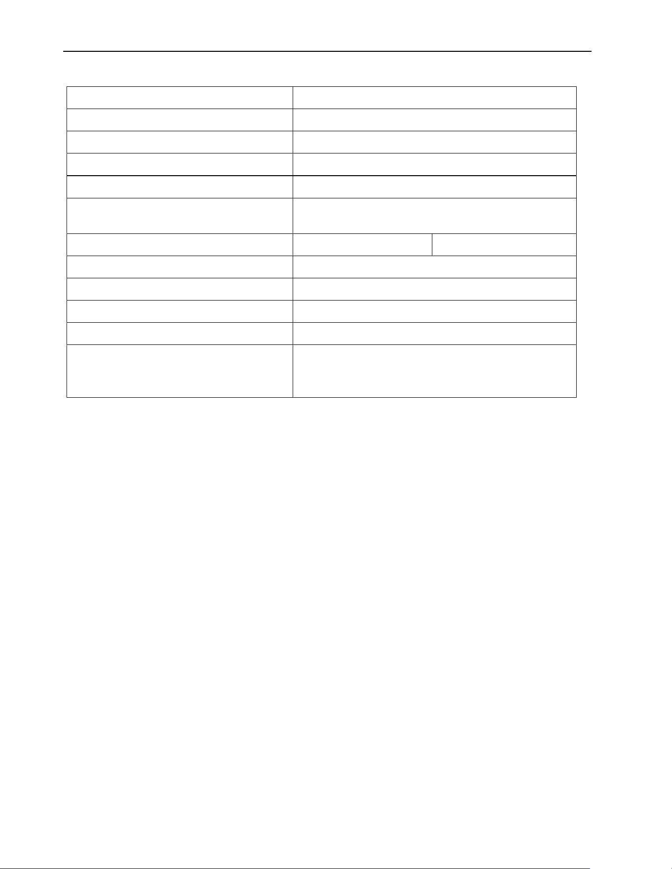
1.2 Appliance performance
(1)
Fuel type
Wood Pellet (Premium grade or better)
(
☨
)
Recommended heating area
[*]
800 to 2,600 ft
2
(74 to 242 m
2
)
Hopper capacity 125 lb (57 kg)
Maximum burn time
[*]
105 h
Maximum heat input rate
(2)
50,800 BTU/h (14.8 kW)
Overall heat output rate
(min. to max.)
(3)
6,966 BTU/h to 28,526 BTU/h (2.04 kW to 8.36
kW)
Average overall efficiency
(3)
76.7% (HHV
(4)
) 84.4% (LHV
(5)
)
Optimum efficiency
(6)
84.4%
Burn rate 1.12 lb/h to 4.63 lb/h (0.51 kg/h to 2.10 kg/h)
Average particulate emissions rate
(7)
0.77 g/h (EPA / CSA B415.1-10)
(8)
Average CO
(9)
12.96 g/h
Average electrical power
consumption
(10)
3.7A (360W) for ignition cycle
2.15A (258W) min. / 2.9A (348W) max. for
continuous operation
[*]
Recommended heating area and maximum burn time may vary subject to location in home, chimney
draft, heat loss factors, climate, fuel type, feed rate, fuel level, and other variables. The recommended
heated area for a given appliance is defined by the manufacturer as its capacity to maintain a minimum
acceptable temperature considering that the space configuration and the presence of heat distribution
systems have a significant impact in making heat circulation optimum.
(
☨
)
Grades of pellet fuel are determined by organizations such as Pellet Fuels Institute (PFI), ENplus and
CANplus.
(1)
Values are as measured per test method, except for the recommended heating area, hopper capacity,
maximum burn time and maximum heat input rate. Results may vary depending on pellet quality,
density, length, and diameter.
(2)
The maximum input thermal power may vary depending on the length of the pellet and the calorific
value of the dry pellet.
(3)
As measured per CSA B415.1-10 stack loss method.
(4)
Higher Heating Value of the fuel.
(5)
Lower Heating Value of the fuel.
(6)
Optimum overall efficiency at a specific burn rate (LHV).
(7)
This appliance is officially tested and certified by an independent agency.
(8)
Tested and certified in compliance with EPA 40 CFR Part 60, ASTM E2515-11, ASTM E2779-10 and
CSA B415.1-10.
(9)
Carbon monoxide.
(10)
Unless stated otherwise, measures were taken directly at the main power source and include all
electrical components present in the appliance.
ECO-65R Installation and Operation Manual
7
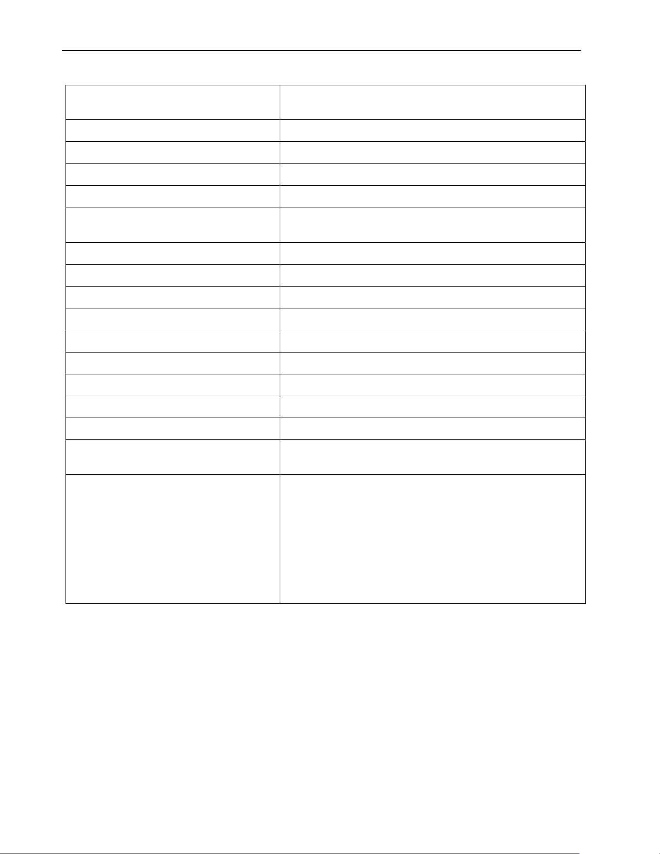
1.3 General Features
Recommended chimney diameter
4 po (see Section 4.3: Equivalent Vent Length
(EVL))
Flue outlet diameter 4 po (100 mm)
Type of chimney ULC/ORD-C441, CAN/ULC S609, UL 641 (TYPE L)
Baffle material Stainless Steel
Approved for alcove installation Not approved
Approved for mobile home
installation
‡
Yes
Shipping weight (without option) 440 lb (200 kg)
Appliance weight (without option) 371 lb (168 kg)
Type of door Single, glass with cast iron frame
Glass type Ceramic glass
Blower Included (up to 500 CFM)
Particulate emission standard EPA / CSA B415.1-10
USA standard (safety) ASTM E1509
Canadian standard (safety) ULC S627
Noise level at 6 feet Min: 53 dBa (+/- 3 dBa) − Max: 59 dBa (+/- 3 dBa)
Electrical requirements
Voltage and frequency: 120VAC and 60Hz
AC Current: 2.15A/120VAC - 3.7A/120VAC
Control board fuses
-Main: 7.5A-250V fast-blow fuse
-Convection blower: 5A-250V fast-blow fuse
-Combustion blower: 3A-250V fast-blow fuse
-Exhaust blower: 3A-250V fast-blow fuse
-Auger motor #1: 3A-250V fast-blow fuse
-Auger motor #2: 3A-250V fast-blow fuse
-Igniter: 5A-250V fast-blow fuse
‡
Mobile home (Canada) or manufactured home (USA): The US department of Housing and Urban
Development describes “manufactured homes” better known as “mobile homes” as followed; buildings
built on fixed wheels and those transported on temporary wheels/axles and set on a permanent foundation.
In Canada, a mobile home is a dwelling for which the manufacture and assembly of each component is
completed or substantially completed prior to being moved to a site for installation on a foundation and
connection to service facilities and which conforms to the CAN/CSA-Z240 MH standard.
ECO-65R Installation and Operation Manual
8
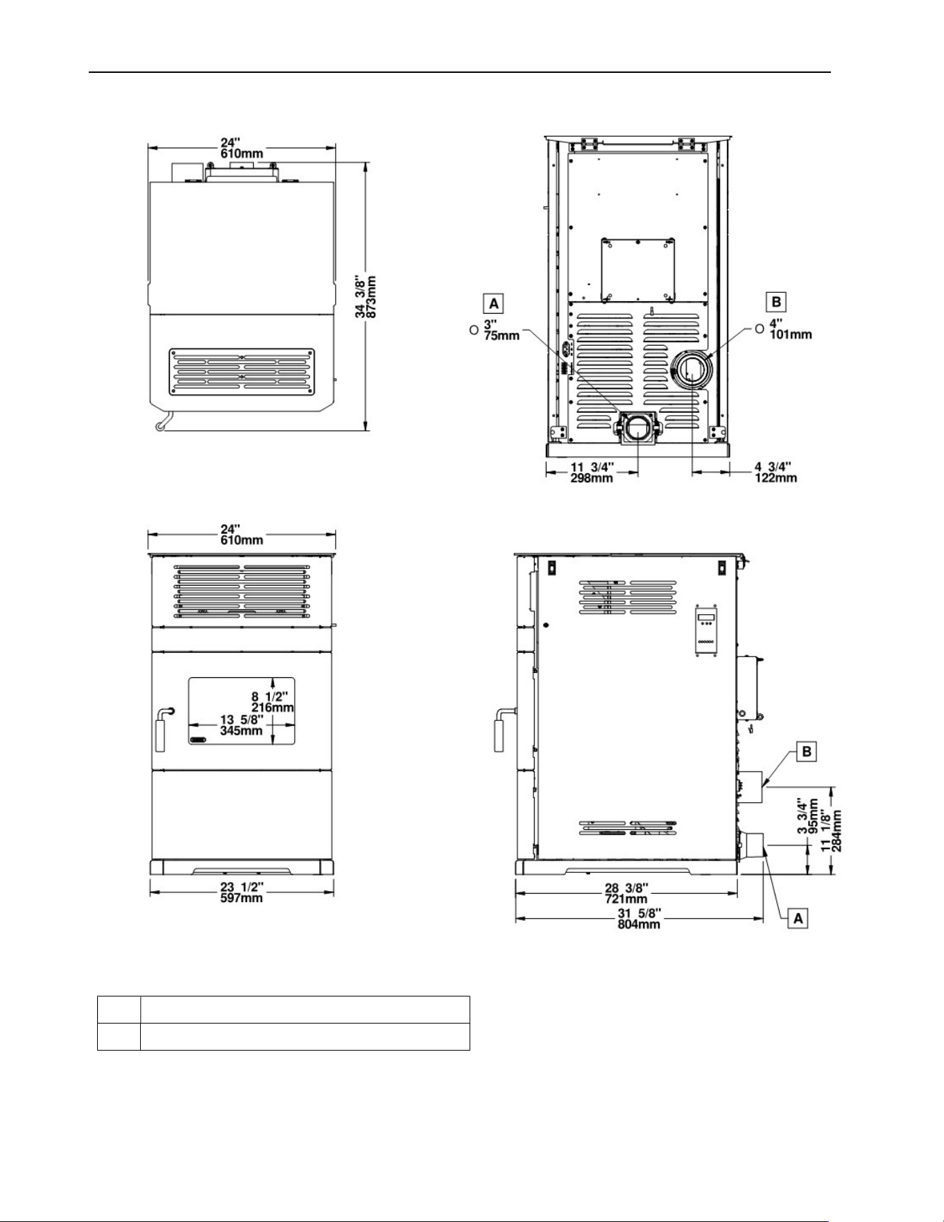
1.4 Overall Exterior Dimensions
A FRESH AIR INTAKE
B FLUE OUTLET

ECO-65R Installation and Operation Manual
9
PART A – INSTALLATION
2 Installation Safety Information
2.1 Installation Warnings, Cautions and Recommendations
PROFESSIONNAL INSTALLATION IS HIGHLY RECOMMENDED.
YOU MAY NEED TO OBTAIN A BUILDING PERMIT FOR THE INSTALLATION OF THIS
STOVE AND ITS VENTING SYSTEM. CONSULT YOUR MUNICIPAL BUILDING
DEPARTMENT OR FIRE DEPARTMENT BEFORE INSTALLATION TO DETERMINE
THE NEED TO OBTAIN ONE. WE RECOMMEND THAT YOU ALSO INFORM YOUR
HOME INSURANCE COMPANY TO FIND OUT IF THE INSTALLATION WILL AFFECT
YOUR POLICY.
THIS STOVE MUST BE CONNECTED TO A STANDARD 120V. 60 HZ GROUNDED
ELECTRICAL OUTLET. DO NOT USE AN ADAPTER PLUG OR SEVER THE
GROUNDING PLUG. DO NOT ROUTE THE ELECTRICAL CORD UNDERNEATH, IN
FRONT OR OVER THE STOVE.
IF THIS STOVE IS NOT PROPERLY INSTALLED, A HOUSE FIRE MAY RESULT. TO
REDUCE THE RISK OF FIRE, FOLLOW THE INSTALLATION INSTRUCTIONS.
BURNING ANY SOLID FUELS GENERATES CARBON MONOXIDE IN LOW
CONCENTRATION. THIS GAS IS EVACUATED BY THE VENTING SYSTEM. IN HIGHER
CONCENTRATIONS, CARBON MONOXIDE IS TOXIC AND MAY CAUSE DEATH. TO
PREVENT THIS, ENSURE THAT YOUR VENTING SYSTEM IS AIRTIGHT.
THIS STOVE IS MOBILE HOME APPROVED AND REQUIRES INSTALLATION OF A
FRESH AIR KIT, SOLD SEPARATELY. THE STOVE MUST BE ATTACHED TO THE
STRUCTURE OF THE MOBILE HOME AND THE STRUCTURAL INTEGRITY OF THE
MOBILE HOME FLOOR, WALL, AND CEILING/ROOF MUST BE MAINTAINED. DO NOT
INSTALL IN A SLEEPING ROOM.
THIS STOVE IS NOT RECOMMENDED TO BE INSTALLED IN A BEDROOM.
THIS STOVE HAS BEEN DEVELOPED AND BUILT FOR RESIDENTIAL
SUPPLEMENTARY HEAT SOURCE. COMMERCIAL AND INDUSTRIAL USE IS
PROHIBITED AND WILL VOID THE WARRANTY.
THE INFORMATION GIVEN ON THE CERTIFICATION LABEL AFFIXED TO THE STOVE
ALWAYS OVERRIDES THE INFORMATION PUBLISHED IN ANY OTHER MEDIA
(OWNER’S MANUAL, CATALOGUES, FLYERS, MAGAZINES AND/OR WEB SITES).
CONNECT THIS STOVE ONLY TO A LISTED PELLET VENT FOR USE WITH SOLID
FUEL OR TO A LINED CHIMNEY CONFORMING TO NATIONAL AND LOCAL
BUILDING CODES.
DO NOT INSTALL A FLUE DAMPER IN THE EXHAUST VENTING SYSTEM OF THIS
UNIT.
DO NOT CONNECT THIS STOVE TO ANY OTHER EXISTING VENTING SYSTEM
SERVING ANOTHER APPLIANCE.

ECO-65R Installation and Operation Manual
10
DO NOT CONNECT TO OR USE IN CONJUNCTION WITH ANY AIR DISTRIBUTION
DUCTWORK.
THE VENTING SYSTEM MUST BE COMPLETELY AIRTIGHT AND PROPERLY
INSTALLED. ALL VENT CONNECTOR JOINTS MUST BE SEALED AND FASTENED IN
ACCORDANCE WITH THE PELLET VENT MANUFACTURER'S INSTRUCTIONS TO
ENSURE CONSISTENT PERFORMANCE AND AVOID SMOKE AND ASH SPILLAGE.
THE VENTING SYSTEM SHOULD BE CHECKED, AT LEAST TWICE A YEAR FOR ANY
BUILDUP OF SOOT OR CREOSOTE.
NEVER BLOCK ANY LOUVERS OF THE STOVE.
IF REQUIRED, A FRESH AIR KIT CAN BE INSTALLED TO SUPPLY COMBUSTION AIR
TO THE ROOM OR SPACE (SEE APPENDIX D: COMBUSTION AIR SUPPLY).
MIXING OF APPLIANCE COMPONENTS FROM DIFFERENT SOURCES OR
MODIFYING COMPONENTS IS PROHIBITED AND WILL VOID THE WARRANTY.
ANY MODIFICATION OF THE STOVE THAT HAS NOT BEEN APPROVED IN WRITING
BY THE TESTING AUTHORITY IS PROHIBITED AND VIOLATES CSA B365 (CANADA),
AND ANSI NFPA 211 (USA).
THIS WOOD HEATER NEEDS PERIODIC INSPECTION AND REPAIRS FOR THE
PROPER OPERATION. IT IS AGAINST FEDERAL REGULATIONS TO OPERATE THIS
WOOD HEATER IN A MANNER INCONSISTENT WITH OPERATING INSTRUCTIONS
IN THIS MANUAL.
THIS WOOD HEATER HAS A MANUFACTURER-SET MINIMUM LOW BURN RATE
THAT MUST NOT BE ALTERED. IT IS AGAINST FEDERAL REGULATIONS TO ALTER
THIS SETTING OR OTHERWISE OPERATE THIS WOOD HEATER IN A MANNER
INCONSISTENT WITH OPERATING INSTRUCTIONS IN THIS MANUAL.
STOVE BUILDER INTERNATIONAL INC. (SBI) GRANTS NO WARRANTY, IMPLIED OR
STATED, FOR THE POOR INSTALLATION OR LACK OF MAINTENANCE OF YOUR
STOVE AND ASSUMES NO RESPONSIBILITY OF ANY CONSEQUENTIAL DAMAGES.
DO NOT INSTALL IN AN ALCOVE.
DO NOT INSTALL IN ANY FIREPLACE.
DO NOT OPERATE THE STOVE WITH THE DOOR OPEN. THIS CAN RESULT IN LOSS
OF EFFICIENCY, FIRE HAZARD, INCOMPLETE COMBUSTION, AND EXPOSURE TO
CARBON MONOXIDE.
ECO-65R Installation and Operation Manual
11
2.2 Regulations Covering Pellet Stove Installation
When installed and operated as described in these instructions, this pellet stove is suitable for
use as a freestanding heater in residential installations.
In Canada, the CSA B365 Installation Code for Solid Fuel Burning Appliances and Equipment
and the CSA C22.1 Canadian National Electrical Code are to be followed in the absence of
local code requirements. In the USA, the ANSI NFPA 211 Standard for Chimneys, Fireplaces,
Vents and Solid Fuel-Burning Appliances and the ANSI NFPA 70 National Electrical Code are
to be followed in the absence of local code requirements.
This stove must be connected to a pellet vent system complying with the requirements for Pellet
Vent in the standards UL 103, UL 641, ULC S629M, CAN/ULC S609 and ULC/ORD C441 or
to a code-approved masonry chimney with a stainless-steel flue liner.
2.3 Before Operating Your Stove
Some minor installation and adjustment are required prior to use:
The handle and door must be adjusted; (see section 7.1.10: Door Adjustment)
The stove must be leveled using threaded legs.
Make sure the fresh air intake back draft shutter works freely.
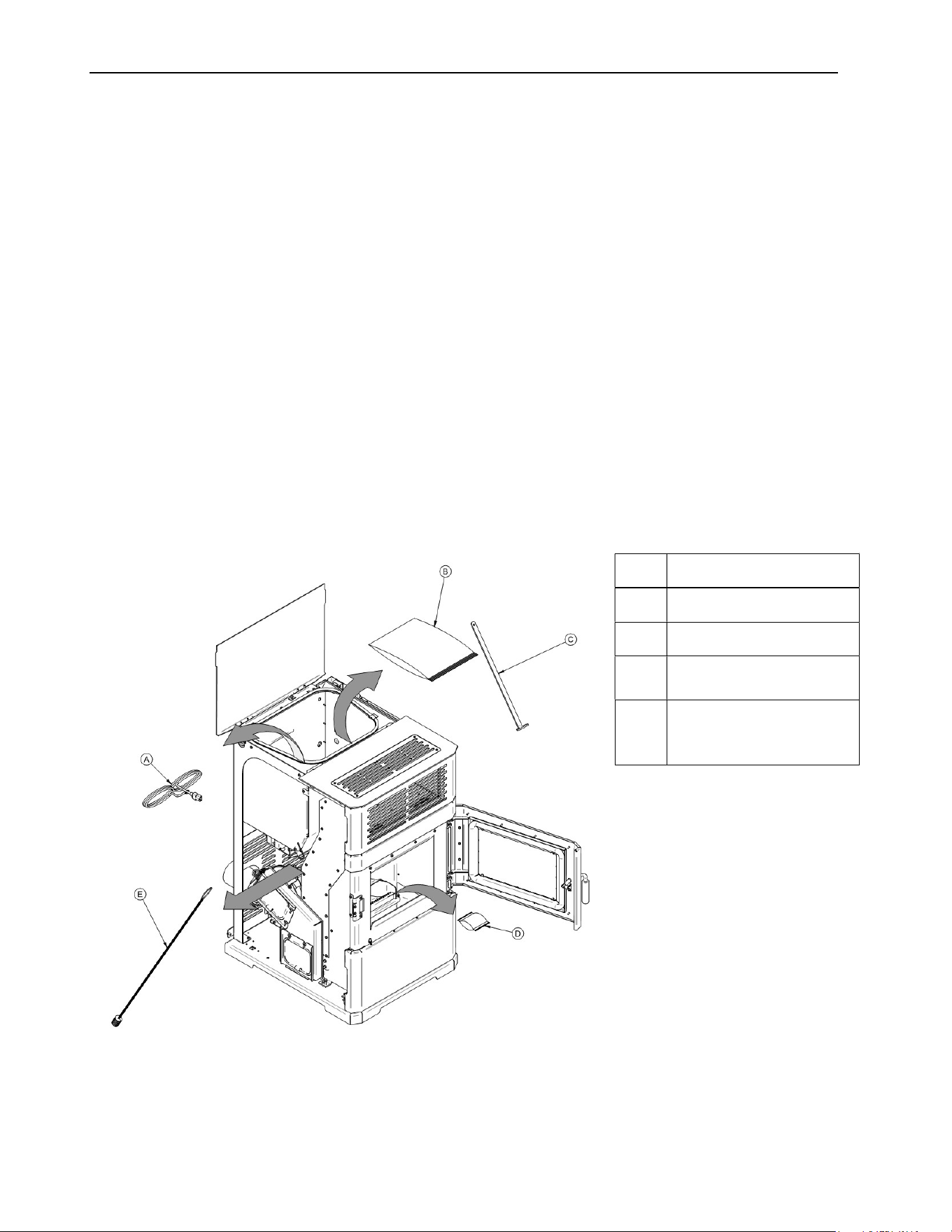
Make sure to remove all tools or accessories that have been inserted in the stove for
transportation purposes (see following illustration.)
A POWER CORD
B OWNER’S MANUAL
C SCRAPER
D
DESICCANT (drying
agent)
E
SWEEPING BRUSH
(the tie wrap must be
cut)
ECO-65R Installation and Operation Manual
12
3 Clearances to Combustible Material
The clearances shown in this section have been determined by tests according to procedures
set out in safety standards ULC S627 (Canada), ASTM E1509 (U.S.A). When the pellet stove
is installed so that its surfaces are at, or beyond, the minimum clearances specified,
combustible surfaces will not overheat under normal and even abnormal operating conditions.
WARNING: NO PART OF THE STOVE MAY BE LOCATED CLOSER TO COMBUSTIBLES
THAN THE MINIMUM CLEARANCES SPECIFIED ON THE CERTIFICATION LABEL.
CAUTION: NO PART OF THE PELLET VENT SYSTEM MAY BE LOCATED CLOSER TO
COMBUSTIBLES THAN THE MINIMUM CLEARANCES SPECIFIED BY THE VENT
MANUFACTURER.
CAUTION: DO NOT USE MAKESHIFT MATERIALS OR MAKE ANY COMPROMISES
WHEN INSTALLING THIS STOVE.
3.1 Certification Label Location
Since the information given on the certification label affixed to the stove always overrides the
information published in any other media (owner’s manual, catalogues, flyers, magazines
and/or web sites), it is important to refer to it in order to have a safe and compliant installation.
In addition, you will find important information about your stove (model, serial number, etc.).
You will find the certification label on the inner side of the hopper lid of the stove.
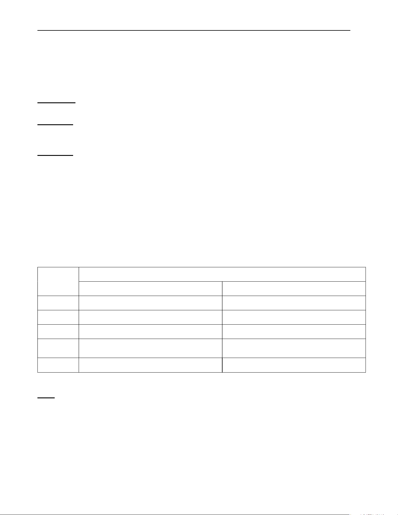
3.2 Minimum Clearances to Combustibles
LETTRE
DÉGAGEMENTS MINIMUM
CANADA É-U.
A* 3″ (76 mm) 3″ (76 mm)
B 6″ (152 mm) 6″ (152 mm)
C 3″ (76 mm) 3″ (76 mm)
D
Refer to vent manufacturer’s
clearances
Refer to vent manufacturer’s
clearances
I** 72″ (1 829 mm) 72″ (1 829 mm)
Note: We recommend leaving 24″ on each side of the stove and 12″ at the back of the
stove in order to facilitate access for maintenance.
* From the fresh air intake.
** Measured from the platform on which the product is installed.
ECO-65R Installation and Operation Manual
13
3.3 Floor Protection
For floor protection clearances refer to the following table.
FLOOR PROTECTION
LETTER
CANADA USA
E 18″ (460 mm)** 6″ (155 mm)
F N/A (USA only) 6″ (155 mm)
G 8″ (205 mm)
N/A (Canada
only)
H 8″ (205 mm)
N/A (Canada
only)
CAUTION: THE STOVE MUST BE PLACED ON A CONTINUOUS (GROUTED JOINTS)
NONCOMBUSTIBLE MATERIAL SUCH AS CERAMIC TILE*, CEMENT BOARD, BRICK,
MILLBOARD OR EQUIVALENT, OR ANY OTHER APPROVED OR LISTED MATERIAL
SUITED FOR FLOOR PROTECTION.
*Any type of tile will require a continuous non-combustible sheet beneath to prevent the possibility of embers
falling through to the combustible floor if cracks or separation should occur in the finished surface, this would
include floor protection for built-in raised hearths. Check local codes for approved alternatives.
**In Canada, you may reduce to the U.S. floor protection requirements (E) ONLY if the following actions are
respected: Allow for the appliance to shut-down and fires to be extinguish. Once completely cool and all blowers
have stopped you may proceed with opening the firebox or ash door.
ECO-65R Installation and Operation Manual
14
4 Venting system
4.1 General
Even though the chimney draft is mechanical, a suitable venting system will ensure a natural
draft which will prevent smoke spillage in your home if a power outage occurs. Moreover, a
suitable venting system configuration will help getting the best efficiency out of your stove when
installed in accordance with the required EVL (see Section 4.3: Equivalent Vent Length
(EVL)).
Even the best stove will not function safely and efficiently as intended if it is not connected to a
suitable venting system.
4.2 Recommendations
In Canada, we recommend that you use a listed pellet vent that meets the CAN/ULC S609 or
ULC/ORD C441 Standard. A pellet vent listed to ULC S629M is also suitable for installation
with this stove.
For the United States, we recommend that you use a listed pellet vent that meets the UL 641
Standard. A pellet vent listed to UL 103 is also suitable for installation with this stove.
This stove can be vented in an existing factory-built or masonry chimney with the addition of a
stainless-steel liner, provided the chimney is more than 4” in diameter. The liner should be
listed and should meet the ULC S635 CAN/ULC S640 standard in Canada and the UL 1777
standard in the USA. Refer to the instructions provided by the vent manufacturer, especially
when passing through a wall, ceiling or roof.
4.3 Equivalent Vent Length (EVL)
Recommended venting system inner pipe diameter is 4”.
To calculate the EVL of your installation, use the following conversions:
Qty Type of pipe EVL equivalent(ft)
1 90° elbow or “T” 5 ft
1 45° elbow 3 ft
1 pied
Horizontal pipe run
1 ft
1 pied
Vertical pipe run 0.5 ft
NOTE: Horizontal runs shall not exceed 9 feet.
NOTE: Never exceed 30 feet of EVL.
ECO-65R Installation and Operation Manual
15
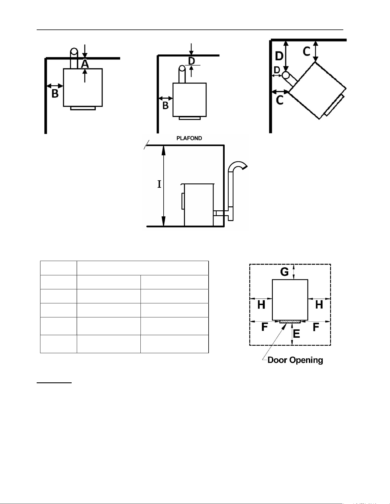
Here is an example to help you calculate Equivalent Vent Length. On the following figure the
EVL can be calculated like this:
2 horizontal runs of 1’ = (2 X 1’) X 1’ = 2’ of EVL
1 elbow 90° or "T" = 5’ of EVL
3 vertical lengths of 4’ = (3 X 4’) X 0.5’ = 6’ of EVL
Total EVL = (2’ + 5’ + 6’) = 13’
NOTE: Do not include the exterior wall termination in the EVL calculation (45° elbow and
termination).
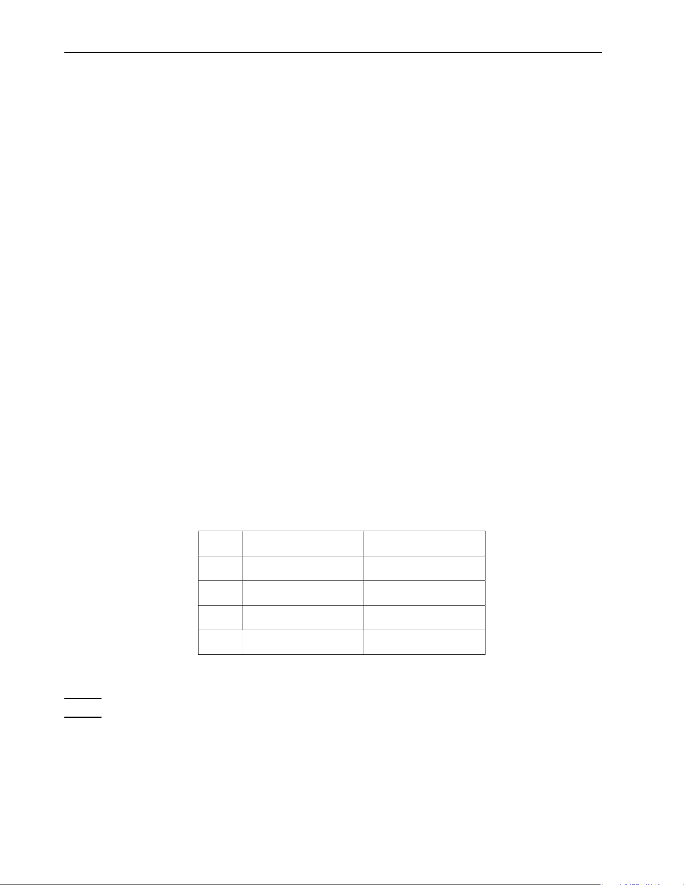
For example, let’s imagine an installation consisting of a horizontal
vent coming out at the back of the stove on a total distance of 8
feet. This horizontal run is followed by a tee and a 6-foot vertical
rise. This type of installation is not acceptable. As you can see,
the vent termination is clearly outside the allowed configuration
zone on the chart because the venting system proposed does not
have at least one foot of vertical rise for each foot of
horizontal run.
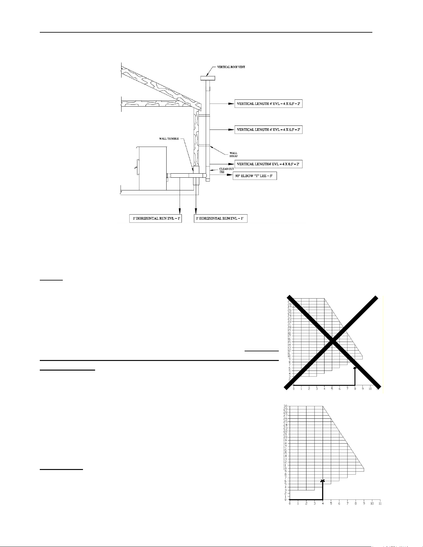
Instead, if the installation consisted of a horizontal vent coming out
at the back of the stove on a total distance of 4 feet, followed by
a tee and a 6-foot vertical rise, it would be acceptable. The
installation end should be within the allowable configuration zone
on the chart since it would have at least one foot of vertical rise
for each foot of horizontal run. Furthermore, the total vertical rise
would be at least 3-foot high.
WARNING: To reduce the risk of smoke spillage there
should always be at least one foot of vertical rise for each
foot of horizontal run. In all cases, at least 3 feet of vertical
rise is needed.
O.K.
ECO-65R Installation and Operation Manual
16
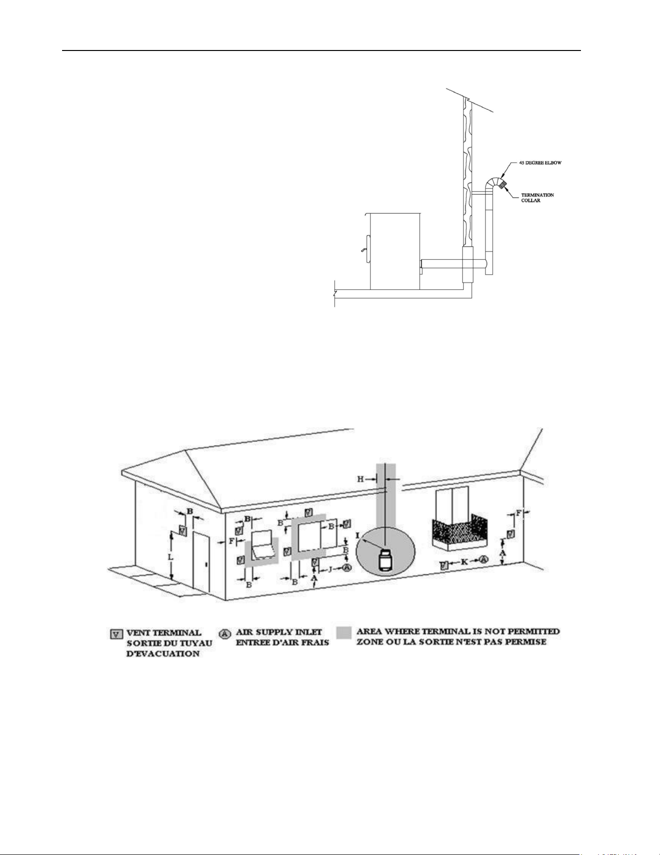
4.4 Termination Location
Termination should not be located so that
hot exhaust gases can be a hazard. They
can reach temperatures of 500°F (260°C)
and cause serious burns.
CAUTION: TERMINATION COLLAR
(SPARK ARRESTER) IS MANDATORY.
4.4.1 Permitted Termination Location
Refer to NFPA 211 (USA) or CSA B365 (Canada) for rules for the distance of exit terminal from
windows and openings. The exit terminal of a mechanical draft system, other than a direct vent
appliance shall be located in accordance with the following.
ECO-65R Installation and Operation Manual
17
Canada:
Letter
Min.
clearances
Description
A 12’’ (30 cm)
Clearances above grade level or any adjacent surface that might
support snow, ice, or debris
B 39’’ (100 cm) Clearance to window or door that may be opened
F 39’’ (100 cm) Clearance to corner or adjacent wall
H 39’’ (100 cm)
Not to be installed above a meter/regulator assembly within 39"
(100 cm) horizontally from the vertical centerline of the regulator
and for 15’ vertically
I 72’’ (183 cm)
Clearance to gas service regulator vent outlet or within 39’’ (100
cm) of an oil tank vent or an oil tank fill inlet
J 39’’ (100 cm) Clearance to the combustion air inlet to any other appliance
K 72’’ (183 cm) Clearance to a mechanical air supply inlet
L 84’’ (213 cm)
Clearance above paved sidewalk or a paved driveway located
on public property
39’’ (100 cm) Clearance to property boundary
A vent shall not terminate underneath a veranda, porch, or deck
United States:
Not Less than 36’’ (91 cm) above any forced air inlet located within 10 feet (305 cm).
Not Less than 48’’ (122 cm) below and horizontally from, or one foot (30 cm) above, any
door, window or gravity air inlet into any building.
Not Less than 24’’ (61 cm) from an adjacent building and not less than 84’’ (213 cm) above
grade when located adjacent to a public walkway.
Cannot be located less than 12 inches (300mm) above grade.
Cannot be located above a gas meter/regulator within 3 feet (900mm) horizontally of the
vertical center line of the regulator.
Not within 6 feet (1.8 meters) of a gas service regulator vent outlet.
Other restrictions may apply. See NFPA 211 for further information.

ECO-65R Installation and Operation Manual
18
4.5 Installation Configurations
4.5.1 Installation Warnings, Cautions and Recommendations Reminder
PROFESSIONNAL INSTALLATION IS HIGHLY RECOMMENDED
THIS STOVE USES A PRESSURIZED VENTING SYSTEM. ALL VENT CONNECTOR
JOINTS MUST BE SEALED AND FASTENED. CONSULT THE PELLET VENT
MANUFACTURER’S INSTRUCTION TO ENSURE PROPER INSTALLATION,
CONSISTENT PERFORMANCE, AND TO AVOID SMOKE AND ASH SPILLAGE.
USE RTV SILICONE (Room Temperature Vulcanization), METALLIC TAPE, AND A
MINIMUM OF THREE SELF-TAPING SCREWS AT ALL JOINT CONNECTIONS TO
ENSURE A TIGHT SEAL.
THE CHIMNEY CONNECTOR SHALL NOT PASS THROUGH AN ATTIC OR ROOF
SPACE, CLOSET OR SIMILAR CONCEALED SPACE OR FLOORS OR CEILING.
INSTALL VENTING SYSTEM AT CLEARANCES SPECIFIED BY THE VENT
MANUFACTURER.
THE USE OF A SPARK ARRESTER AT THE END OF THE TERMINATION IS
MANDATORY.
ECO-65R Installation and Operation Manual
19
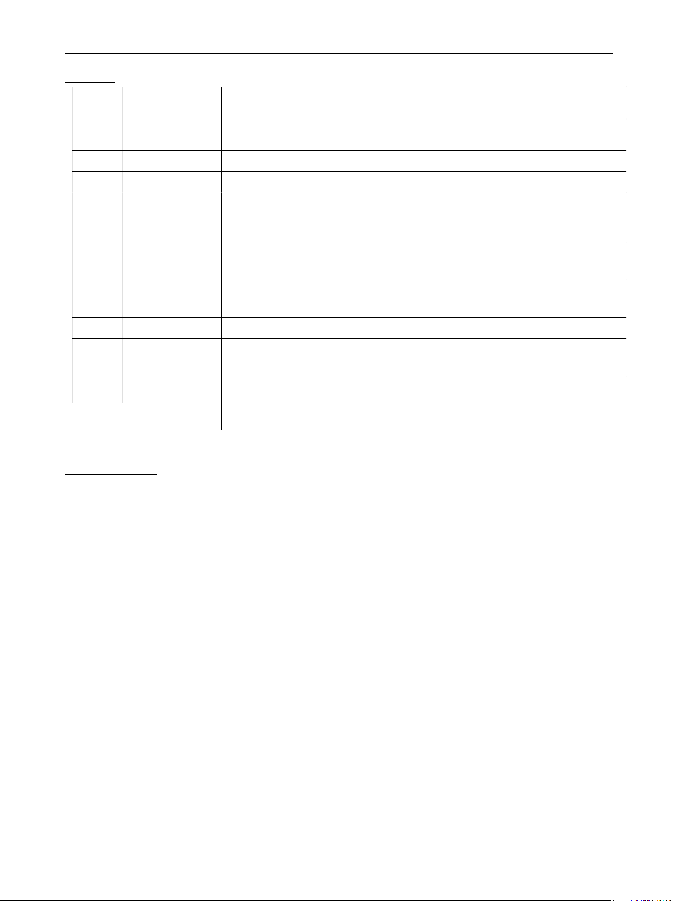
4.5.2 Through Wall Installation (Main Floor or Basement)
1. Position appliance following clearances vent manufacturer’s instructions
2. Install a stove adapter or a stove adapter tee onto the appliance flue collar.
3. Locate the position of the exhaust pipe in the wall and cut a hole of the appropriate size for
vent in the wall.
4. Install wall thimble as per vent manufacturer’s instructions.
5. Ensure you install enough horizontal pipe length to exceed the exterior wall of 6 inches.
Install a tee section to the pipe passing through the wall.
6. Run the vent vertically up the wall for at least 36". Refer to the vent manufacturer’s
instructions for clearances to combustible materials and installation of wall bands.
7. Install a 90 degrees elbow facing out from the wall and then attach a 45 degrees elbow
facing towards the ground. The termination of the vent must include a spark arrester,
fastened to the 45 degrees elbow.
8. Sealed outside wall thimbles with high temperature waterproof silicone sealant.
CAUTION: TO REDUCE THE RISK OF SMOKE SPILLAGE THERE SHOULD ALWAYS BE
AT LEAST 12” (30 CM) OF VERTICAL RISE FOR EACH FOOT OF HORIZONTAL RUN. IN
ALL CASES, AT LEAST 36” (91 CM) OF VERTICAL RISE IS NEEDED BEFORE THE
TERMINATION.
WARNING: TERMINATION SHOULD NOT BE LOCATED SO THAT HOT EXHAUST GASES
CAN BE A HAZARD. EXHAUST GASES CAN REACH TEMPERATURES OF 500°F (260°C)
AND CAUSE SERIOUS BURNS. SEE SECTION 4.4.1: PERMITTED TERMINATION
LOCATION.
ECO-65R Installation and Operation Manual
20
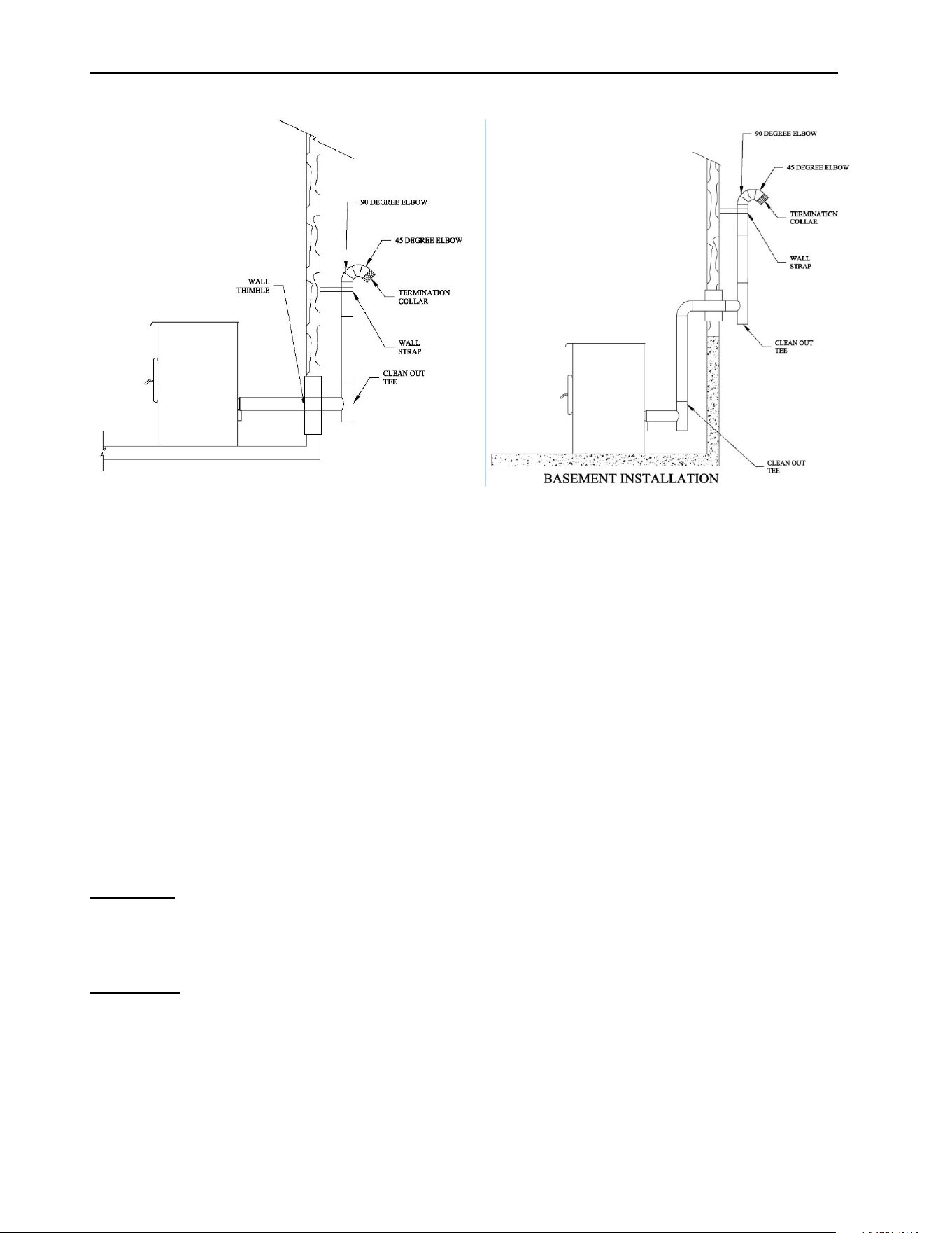
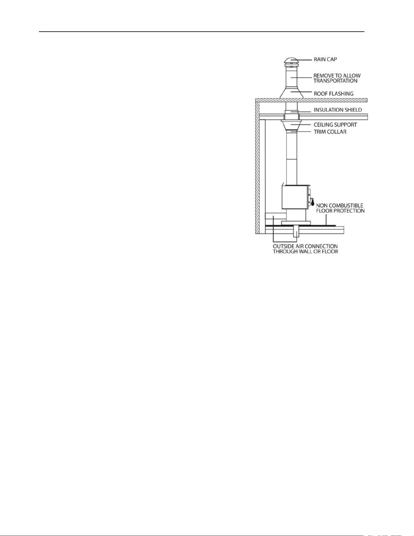
4.5.3 Through Roof Installation
1. Position appliance following clearances
and following vent manufacturer’s
instructions.
2. Install a stove adapter or a stove
adapter tee onto the appliance flue
collar. If necessary, use a horizontal
additional length between the flue outlet
and the tee.
3. Drop the plumb line over the center of
the tee outlet and mark location on the
ceiling.
4. Cut a hole for appropriate ceiling
support. Frame rough opening.
5. Install ceiling support and the first vent
section as per vent manufacturer’s
instructions.
6. Install a firestop radiation shield on any
subsequent ceiling/floor, except for the
attic where an attic insulation shield is
required.
7. Run the necessary section of vent
vertically so the rain cap exceeds the
highest point of the roof at least 24" in
United States and at least 36" in
Canada.
8. Install roof support.
9. . Install roof flashing and rain cap as per
manufacturer’s instructions. If
necessary, install a storm collar.
ECO-65R Installation and Operation Manual
21
4.5.4 Through a Factory Built Chimney
To make an installation through a factory-
built chimney, run a 4" stainless steel liner
inside the factory-built chimney.
1. Position stove following clearances given
and following vent manufacturer’s
instructions.
2. Install a stove adapter or a stove adapter
tee onto the appliance flue collar. If
necessary, use a horizontal additional
length between the flue outlet and the
tee.
3. Use a proper chimney adaptor for your
installation.
4. Run the number of sections of vent
necessary to go through the chimney
adaptor into the chimney.
5. Connect the vent to a stainless steel 4"
liner according to the vent
manufacturer’s instruction.
6. Install roof flashing and rain cap as per
manufacturer’s instructions. If necessary,
install and seal a storm collar.
WARNING: IN THE U.S., THE USE OF A STAINLESS-STEEL LINER IS MANDATORY. IN
CANADA, IT IS NOT MANDATORY BUT IS STRONGLY RECOMMENDED.
NOTE: VENTING DIRECTLY IN AN OVERSIZED CHIMNEY AND OMITTING THE USE OF
A STAINLESS-STEEL LINER CAN AFFECT CHIMNEY DRAFT AND DECREASE STOVE
PERFORMANCES.
ECO-65R Installation and Operation Manual
22
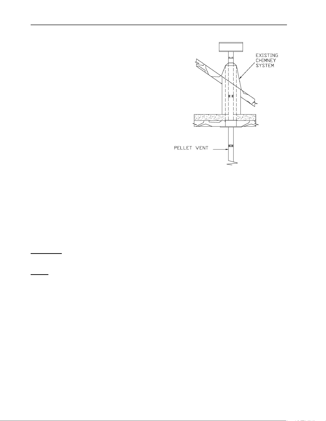
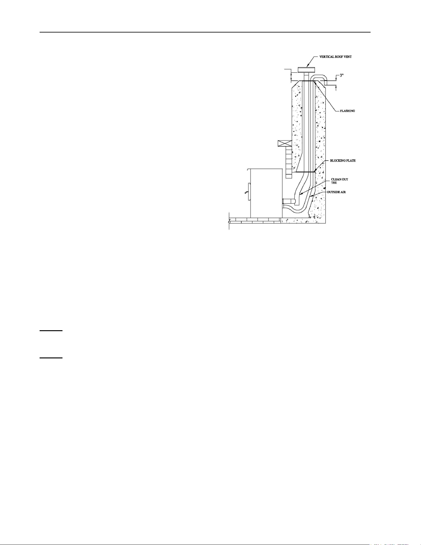
4.5.5 Through an Existing Masonry Fireplace
1. Position stove, following clearances and
following vent manufacturer’s
instructions
2. Build and install a blocking plate inside
the chimney to seal the fireplace damper.
Stainless steel plate and screws are
recommended. Cut a hole for the exhaust
pipe. If needed, cut a second hole for the
air intake pipe (see Appendix D:
Combustion Air Supply).
3. Attach a section of pipe and clean out tee
to the flue outlet, making sure the clean
out tee is centered in the chimney flue
area.
4. Install a vented flashing at the top of the
fireplace chimney. Stainless steel plate
and screws are recommended. Cut a
hole for the vent pipe. If needed, cut a
second hole for the air intake pipe. Seal
all joints with high temperature
waterproof silicone sealant to prevent
water leakage.
5. Seal and install vertical roof vent. If
required, seal and install a storm collar.
NOTE: THE STRUCTURAL CONDITION OF THE MASONRY CHIMNEY MUST FIRST BE
INSPECTED BY A QUALIFIED CHIMNEY SWEEP OR INSTALLER.
NOTE: YOU WILL NEED A PIPE LENGTH EQUAL TO THE CHIMNEY HEIGHT FROM THE
HEARTH. IF OUTSIDE COMBUSTION AIR IS TO BE USED, YOU WILL NEED A PIPE
LENGTH SUPERIOR FROM 12 TO 18 INCHES (30 TO 46 CM) OF THE CHIMNEY HEIGHT
TO ENSURE A PROPER STOVE BEHAVIOUR.
12”-18”
ECO-65R Installation and Operation Manual
23
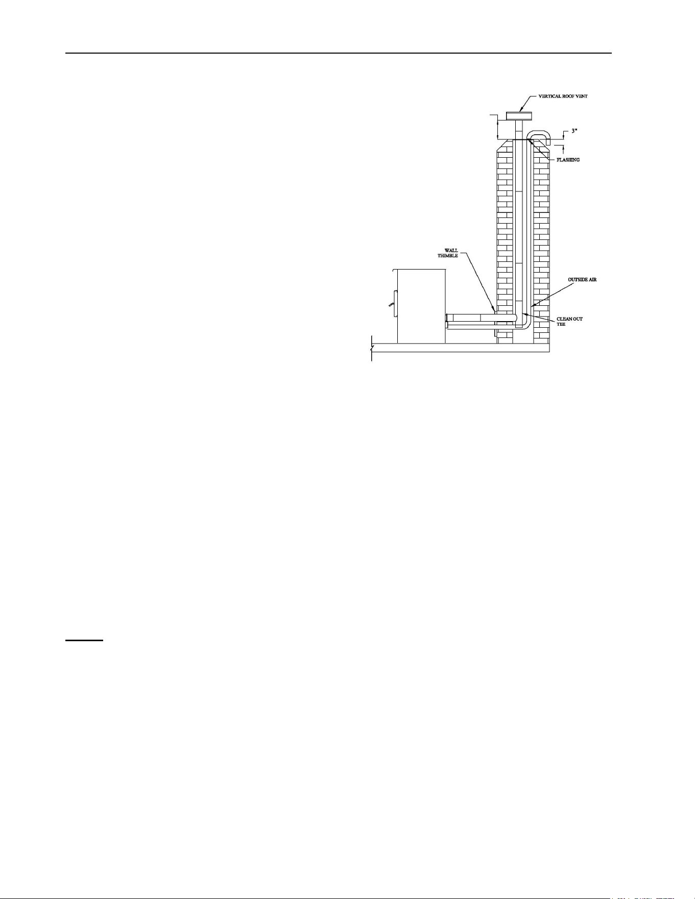
4.5.6 Through an Existing Masonry Chimney
1. Position stove following clearances
following vent manufacturer’s
instructions.
2. Mark the center of the hole where the
vent pipe will go through the masonry
chimney.
3. It is necessary to make a hole in the
masonry with a one-inch diameter
greater than the diameter of the vent pipe
used.
4. Install the cleanout tee at the bottom of
the vertical vent system and lower it
down the chimney until the center branch
of the tee is aligned with the hole in the
masonry.
5. Connect the horizontal vent pipe to the cleanout tee by pushing it through the hole in the
masonry
6. If desired, once the horizontal pipe is in place, the space between the pipe and masonry
may be filled with high-temperature grout
7. Install a vented flashing at the top of the masonry chimney. Stainless steel plate and screws
are recommended. Cut a hole for the vent pipe. If needed, cut a second hole for the air
intake pipe. Seal all joints with high temperature waterproof silicone sealant to prevent water
leakage.
8. Install and seal flashing with high temperature waterproof silicone sealant.
9. Seal and install vertical roof vent. If required, seal and install a storm collar.
10. . If desired, install a trim collar and use an additional horizontal vent pipe length, if required,
to connect the stove to the chimney.
NOTE: YOU WILL NEED A PIPE LENGTH EQUAL TO THE CHIMNEY HEIGHT FROM THE
HEARTH. IF OUTSIDE COMBUSTION AIR IS TO BE USED, YOU WILL NEED A PIPE
LENGTH SUPERIOR FROM 12 TO 18 INCHES (30 TO 46 CM) OF THE CHIMNEY HEIGHT
TO ENSURE A PROPER STOVE BEHAVIOUR.
12”-18”
ECO-65R Installation and Operation Manual
24
4.5.7 Factory-Built Metal Chimneys in Mobile Homes
For use in a mobile home in Canada, this pellet stove
must be connected to a vent system certified according to
the standard or ULC/ORD-C441 or CAN/ULC-S609. A
vent system meeting the requirements of ULC S629 can
also be used for 650°C Factory-built chimney.
For use in a manufactured home in the United States, this
pellet stove must be connected to a venting system that
meets the requirements of UL 641 standard. A vent
system that meets the requirements of UL 103 HT type
standard may also be used.
To maintain an effective vapor barrier, insulation and
waterproof at the chimney and outside flue pipe, a roof
flashing must be installed and sealed with silicone
adhesive.

ECO-65R Installation and Operation Manual
25
PART B - OPERATION
4.6 General Information
4.7 Operation Warnings, Cautions and Recommendations
KEEP THIS MANUAL FOR REFERENCE.
DURING THE FIRST FEW FIRES, YOUR STOVE WILL EMIT AN ODOR AND A SMALL
AMOUNT OF FUMES AS THE HIGH TEMPERATURE PAINT CURES OR BECOMES
SEASONED TO THE METAL. MAINTAINING SMALLER FIRES WILL MINIMIZE THIS.
AVOID PLACING ITEMS ON STOVETOP DURING THIS PERIOD TO AVOID DAMAGING
THE PAINT SURFACE. MAKE SURE THE ROOM IS WELL-VENTILATED. OPEN
WINDOWS. ODORS AND FUMES RELEASED DURING THIS PROCESS ARE
UNPLEASANT BUT THEY ARE NOT TOXIC. ONCE YOU HAVE BURNED THE FIRST
40LBS OF PELLETS, IT IS RECOMMENDED TO INSPECT THE STOVE AND THE
VENTING SYSTEM TO MAKE SURE THAT THERE IS NO LEAKS.
HOT WHILE IN OPERATION, KEEP CHILDREN, CLOTHING AND FURNITURE AWAY.
CONTACT MAY CAUSE SKIN BURNS. GLOVES MAY BE NEEDED FOR STOVE
OPERATION.
IT IS HIGHLY RECOMMENDED THAT THE USER BUYS THIS PRODUCT FROM A
RETAILER WHO CAN PROVIDE INSTALLATION AND MAINTENANCE ADVICE.
THIS STOVE MUST SERVE AS A SUPPLEMENTARY HEAT SOURCE. AN
ALTERNATIVE HEAT SOURCE SHOULD BE AVAILABLE IN THE HOME IF NEEDED.
THE MANUFACTURER CANNOT BE HELD RESPONSIBLE FOR ADDITIONAL
HEATING COSTS ASSOCIATED WITH THE USE OF AN ALTERNATIVE HEAT
SOURCE.
USING A STOVE WITH CRACKED OR BROKEN COMPONENTS, SUCH AS GLASS OR
BAFFLE MAY PRODUCE AN UNSAFE CONDITION AND MAY DAMAGE THE STOVE.
NEVER USE GASOLINE, GASOLINE-TYPE LANTERN FUEL (NAPHTHA), FUEL OIL,
MOTOR OIL, KEROSENE, CHARCOAL LIGHTER FLUID, OR SIMILAR LIQUIDS OR
AEROSOLS. KEEP ALL SUCH LIQUIDS OR AEROSOLS WELL AWAY FROM THE
STOVE WHILE IT IS IN USE.
DO NOT STORE FUEL WITHIN STOVE MINIMUM CLEARANCES TO COMBUSTIBLE.
THIS STOVE SHOULD BE MAINTAINED AND OPERATED AT ALL TIMES IN
ACCORDANCE WITH THESE INSTRUCTIONS. NOT FOLLOWING THE
INSTRUCTIONS OF THIS MANUAL MAY CAUSE SMOKE SPILLAGE AND OTHER
POTENTIAL HAZARDS. IT IS ALWAYS RECOMMENDED TO INSTALL SMOKE
DETECTORS, CARBON MONOXIDE MONITORS AND FIRE EXTINGUISHER IN A
CONVENIENT LOCATION.
A SMOKE DETECTOR LOCATED IN THE PROXIMITY OF THE STOVE MAY BE
ACTIVATED WHEN THE DOOR OF THE STOVE IS OPEN TO RELOAD OR TO STIR.
THE VIEWING DOOR MUST BE CLOSED AND LATCHED AT ALL TIMES DURING
OPERATION. THE ASH DRAWER ACCESS PANEL MUST ALSO BE CLOSED DURING
OPERATION.

ECO-65R Installation and Operation Manual
26
NEVER TRY TO REPAIR OR REPLACE ANY PART OF THE STOVE UNLESS
INSTRUCTIONS ARE GIVEN BY THE MANUFACTURER. ALL OTHER WORK SHOULD
BE DONE BY A TRAINED TECHNICIAN.
DO NOT OPERATE THE STOVE IF THE FLAME BECOMES DARK AND SOOTY OR IF
THE BURN POT OVERFILLS WITH PELLETS. TURN THE STOVE OFF, INSPECT IT,
AND CALL YOUR DEALER.
TURNING THE STOVE OFF DOES NOT DISCONNECT ALL POWER FROM THE
STOVE. DISCONNECT THE POWER CORD BEFORE PERFORMING ANY
MAINTENANCE OR REPAIRS ON THE STOVE.
ALLOW THE STOVE TO COOL BEFORE CARRYING OUT ANY MAINTENANCE OR
CLEANING. ASHES SHOULD BE PLACED IN A METAL CONTAINER WITH A TIGHT-
FITTING LID. THE CLOSED METAL CONTAINER SHOULD BE PLACED ON A
NONCOMBUSTIBLE FLOOR OR ON THE GROUND, WELL AWAY FROM ALL
COMBUSTIBLE MATERIALS, PENDING FINAL DISPOSAL. IF THE ASHES ARE
DISPOSED OF BY BURIAL IN SOIL OR OTHERWISE LOCALLY DISPERSED, THEY
SHOULD BE RETAINED IN THE CLOSED CONTAINER UNTIL ALL ASHES HAVE
BEEN THOROUGHLY COOLED.
DO NOT OPERATE THE STOVE IF YOU SMELL OR SEE SMOKE. TURN IT OFF,
MONITOR IT AND CALL YOUR DEALER IF NECESSARY. DO NOT UNPLUG IT. NEVER
OPEN THE DOOR.
IT IS RECOMMENDED TO UNPLUG THE STOVE WHEN IT’S NOT IN USE FOR
PROLONGED AMOUNT OF TIME (I.E. DURING SUMMER). SENSORS ON THE STOVE
ARE ACTIVATED BY HEAT AND COULD ACTIVATE THE FANS EVEN IF THE STOVE
IS NOT IN FUNCTION.
THIS STOVE REQUIRES REGULAR MAINTENANCE AND CLEANING. FAILURE TO
FOLLOW THE MAINTENANCE SCHEDULE (SEE SECTION 7.1.1: RECOMMENDED
MAINTENANCE SCHEDULE) WILL REDUCE THE STOVE PERFORMANCE AND
COULD EVENTUALLY DAMAGE IT. IT ALSO MAY LED TO SMOKE SPILLAGE IN
YOUR HOME.
THIS STOVE IS DESIGNED AND TESTED TO BURN ONLY WOOD PELLETS. ANY
OTHER TYPE OF FUEL BURNED IN THIS HEATER WILL VOID THE WARRANTY.
HOPPER SHOULD ONLY CONTAIN PELLETS. HOPPER SHOULD BE KEPT FREE OF
ANY FOREIGN OBJECTS AT ALL TIME TO PREVENT ANY DAMAGE TO THE STOVE.
THE STOVE WILL NOT OPERATE DURING A POWER OUTAGE. IF AN OUTAGE DOES
OCCUR, CHECK THE STOVE FOR SMOKE SPILLAGE. OPENING A WINDOW WILL
PREVENT NEGATIVE PRESSURE AND SMOKE SPILLAGE IN THE ROOM.
DO NOT UNPLUG THE STOVE IF YOU SUSPECT IT IS MALFUNCTIONING. TURN IT
OFF, MONITOR IT AND CALL YOUR DEALER IF NECESSARY.
THIS STOVE IS DESIGNED TO PROVIDE THE OPTIMUM PROPORTIONS OF FUEL
AND AIR TO THE FIRE IN ORDER TO BURN FREE OF SMOKE AND SOOT. ANY
BLOCKAGE OF THE AIR SUPPLY TO OR FROM THE STOVE WILL SERIOUSLY
DECREASE ITS PERFORMANCE AND WILL BE EVIDENT BY A SMOKING EXHAUST,
A SOOT BUILDUP ON THE WINDOW AND ON OUTSIDE WALLS. FOR BEST
ECO-65R Installation and Operation Manual
27
OPERATION, THE ASH CONTENT OF THE PELLET FUEL SHOULD BE LESS THAN
1% AND THE CALORIFIC VALUE APPROXIMATELY 8,500 BTU/LB. OTHERS FUELS
WITH A HIGH ASH CONTENT WILL REQUIRE A HIGHER LEVEL OF MAINTENANCE
AND CLEANING.
THE STOVE WILL NOT OPERATE USING NATURAL DRAFT OR WITHOUT A POWER
SOURCE TO ACTIVATE THE BLOWER SYSTEMS AND FUEL FEED SYSTEM.
STOVE BUILDER INTERNATIONAL INC. GRANTS NO WARRANTY, IMPLIED OR
STATED, FOR IMPROPER INSTALLATION OR LACK OF MAINTENANCE OF YOUR
STOVE, AND ASSUMES NO RESPONSIBILITY OF ANY CONSEQUENTIAL DAMAGES.
IF YOU NOTICE A SMOLDERING FIRE (BURNPOT FULL BUT NO VISIBLE FLAME)
AND A HEAVY SMOKE BUILDUP IN FIREBOX, IMMEDIATELY TURN OFF THE STOVE,
BUT DO NOT UNPLUG IT. DO NOT OPEN THE DOOR OR THE HOPPER LID. MAKE
SURE THAT THE FRESH AIR INTAKE SHUTTER WORKS FREELY. WAIT UNTIL
SMOKE INSIDE THE FIREBOX CLEARS AND BLOWERS SHUT DOWN. DO AS
INSTRUCTED IN “EVERYDAY STARTUP” THEN ATTEMPT TO RESTART THE STOVE.
IF THE PROBLEM PERSISTS, CONTACT YOUR DEALER. NOTE THAT SMOKE BUILD-
UP DURING IGNITION MAY OCCUR. SMOKE CAN ACCUMULATE IN THE FIREBOX
FOR A FEW SECONDS JUST BEFORE THE IGNITOR IS HOT ENOUGH TO FIRE-UP
THE PELLETS IN THE BURN POT. THIS IS NORMAL. AS SOON AS THERE IS FIRE
IN THE BURN POT, SMOKE WILL DISAPPEAR.
MAINTAIN PROPER VENTILATION. IT IS IMPORTANT THAT ADEQUATE OXYGEN IS
BEING SUPPLIED TO THE FIRE FOR PROPER COMBUSTION. DURING THE WINTER
SEASON, MAKE SURE THAT THE FRESH AIR INTAKE IS FREE OF ANY ICE, SNOW,
ETC., AS THIS WILL STARVE THE FIRE OF AIR AND PREVENT THE PROPER
OPERATION OF THE STOVE. MAKE SURE THE FRESH AIR INTAKE BACKDRAFT
SHUTTER WORKS FREELY.
OPERATING YOUR STOVE AT THE MAXIMUM SETTING DURING A LONG PERIOD
OF TIME MAY REDUCE THE STOVE AND ITS COMPONENTS LIFE EXPECTANCY.
WARNING:
This product can expose you to chemicals including carbon monoxide,
which is known to the State of California to cause cancer, birth defects or other
reproductive harm. For more information go to www.P65warnings.ca.gov/
4.7.1 Zone Heating and How to Make It Work for You
Your new pellet stove is a space heater, which means it is intended to heat the area it is
installed in, as well as spaces that connect to that area, although to a lower temperature. This
is called zone heating and it is an increasingly popular way to heat homes or spaces within
homes.
Zone heating can be used to supplement another heating system by heating a particular space
within a home, such as a basement family room or an addition that lacks another heat source.
ECO-65R Installation and Operation Manual
28
Although the stove may be able to heat the main living areas of your house to an adequate
temperature, this stove must serve as a supplementary heat source. You should have a
conventional oil, gas or electric additional heating system to provide heating in the home. The
manufacturer cannot be responsible for additional heating costs associated with the use of an
alternative heat source in case of stove failure or power outage.
Your success with zone heating will depend on several factors: Proper stove size, stove
location, heating area, house layout, insulation and your climate zone.
4.8 Combustible
4.8.1 Proper Fuel
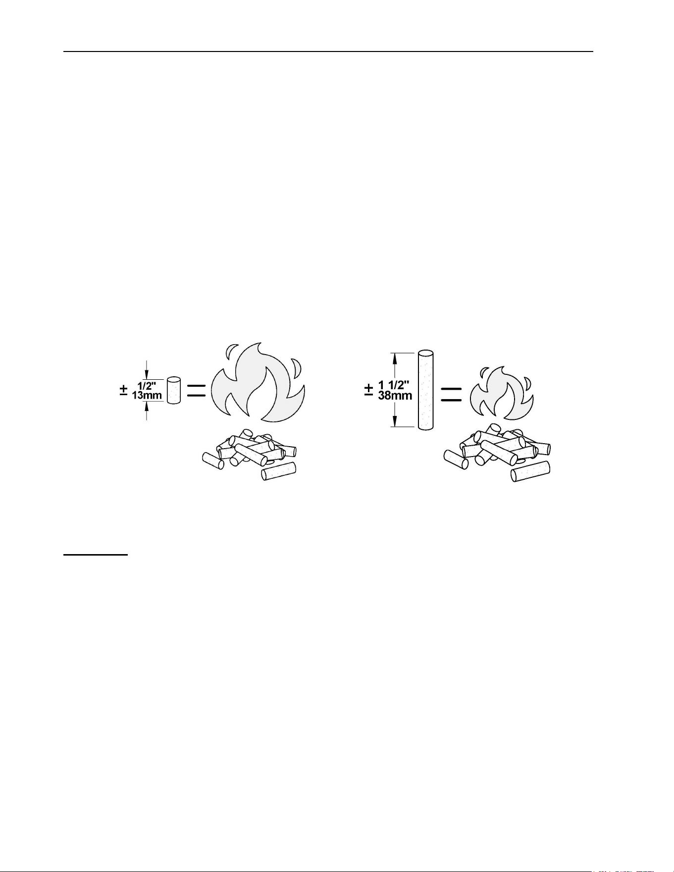
Each type of pellet has its properties and will burn differently. The amount of ashes produced
can also vary greatly. Conventional pellets are those ¼” or 5/16” in diameter and not over 1”
long. Longer or thicker pellets will affect the constancy of pellet feed.
For example, if the pellets are very short, they will have more ease to accumulate and pile into
the feed screws. Thus, the volume of pellets will be denser, which will lead to an increase in
BTU. By contrast, longer pellets will pile less so the BTU will be reduced.
The bottom-feed system of this stove is designed and tested specifically for use with wood
pellets.
WARNING: BURNING OTHER TYPES OF PELLETS IS PROHIBITED. IT VIOLATES THE
BUILDING CODES FOR WHICH THE STOVE HAS BEEN APPROVED AND WILL VOID THE
WARRANTY
ECO-65R Installation and Operation Manual
29
DO NOT BURN:
- COAL.
- GARBAGE.
- LAWN CLIPPINGS OR YARD WASTE.
- MATERIALS CONTAINING RUBBER,
INCLUDING TIRES.
- MATERIALS CONTAINING PLASTIC.
- WASTE PETROLEUM PRODUCTS,
PAINTS OR PAINT THINNERS, OR
ASPHALT PRODUCTS.
- MATERIALS CONTAINING
ASBESTOS.
- CONSTRUCTION OR DEMOLITION
DEBRIS.
- RAILROAD TIES OR PRESSURE-
TREATED WOOD.
- MANURE OR ANIMAL REMAINS.
- SALTWATER DRIFTWOOD OR
OTHER PREVIOUSLY SALT WATER
SATURATED MATERIALS.
- UNSEASONED WOOD; OR
- PAPER PRODUCTS, CARDBOARD,
PLYWOOD, OR PARTICLE BOARD.
THE PROHIBITION AGAINST
BURNING THESE MATERIALS DOES
NOT PROHIBIT THE USE OF FIRE
STARTERS MADE FROM PAPER,
CARDBOARD, SAW DUST, WAX AND
SIMILAR SUBSTANCES FOR THE
PURPOSE OF STARTING A FIRE IN
AN AFFECTED WOOD HEATER.
Burning these materials may result in the
release of toxic fumes or render the
heater ineffective and cause smoke
4.8.2 Where to Store Bags of Pellets
We recommend that you store your bags of pellets in a dry and well-ventilated area if possible.
Using dry pellets will increase the performance of your stove. You may want to have a bag or
two in the same room as your stove for refueling but make sure to respect the minimum
clearances to combustible materials and the space required for refilling and ash removal.
ECO-65R Installation and Operation Manual
30
5 Stove Controls
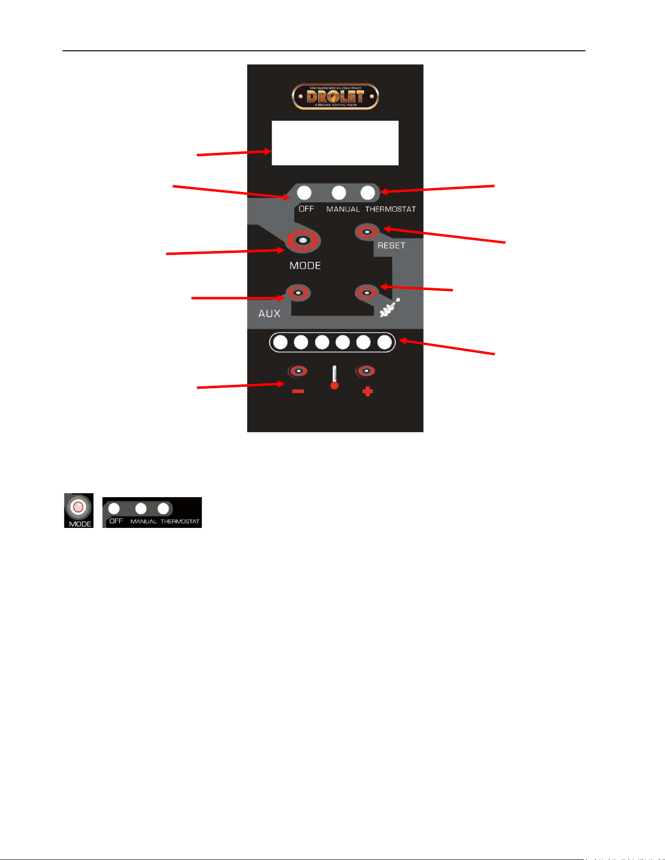
5.1 Control Panel
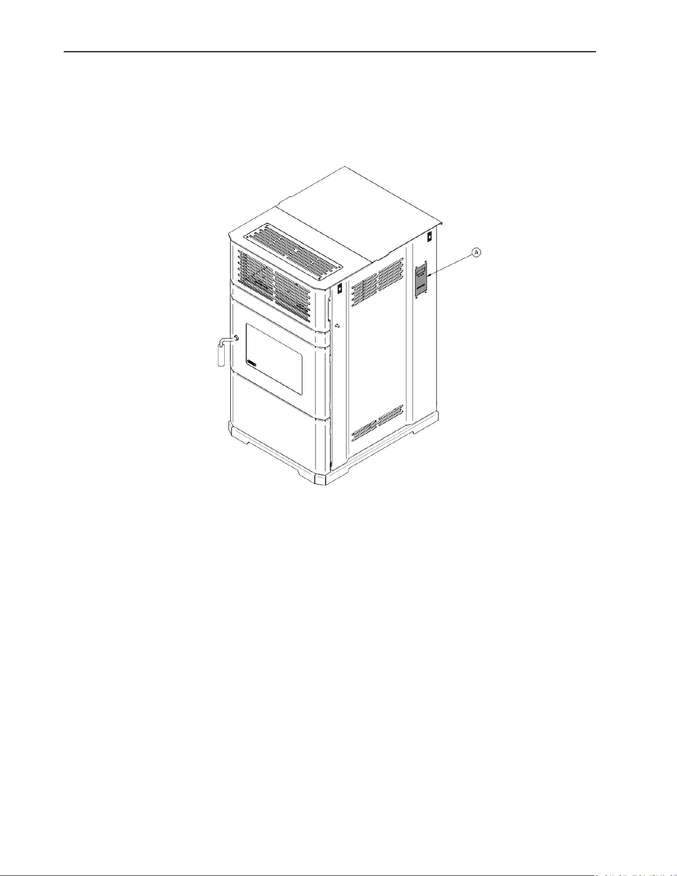
The blowers and automatic fuel supply are controlled from a control panel (A) on the right-hand
side of the ECO-65R. The control panel functions are as follows:
ECO-65R Installation and Operation Manual
31
Control panel screen
Operation mode:
OFF
MANUAL
THERMOSTAT:
Thermostatic control
(optional)
Button to select
between modes
Button to clear
most error codes
Button to change the
convection fan speeds
Button to feed and start
when the auger is empty
Pellet burns rate
Button + and – allows
to select the heat level
5.1.1 Mode Button
When the mode switch is pressed, you will be able to choose the Manual or the Thermostat
mode, or to turn off the appliance. If the Manual mode is selected, the stove will automatically
ignite. At this time, the heat level must be selected manually to adjust the stove’s heat output
to the desired level. If the thermostat mode is selected, the stove will automatically modulate
between the lowest heat level and the heat level selected to keep the room temperature at the
thermostat’s setting (see Section 6.6.1: Pilot mode selection). No fire starter is necessary to
ignite the unit. The auger will feed fuel and the electric igniter will start. If the unit doesn’t ignite
within 12 minutes, the stove will start another ignition cycle. If ignition fails a second time, a
warning message will appear on the control panel.
The Heat Level may be selected during the ignition cycle. However, the unit will only feed fuel
at the desired heat level setting when the heat sensor located into the stove will receive a signal
indicating that the unit has been fully ignited. This may take anywhere between 10 and 15
minutes.
ECO-65R Installation and Operation Manual
32
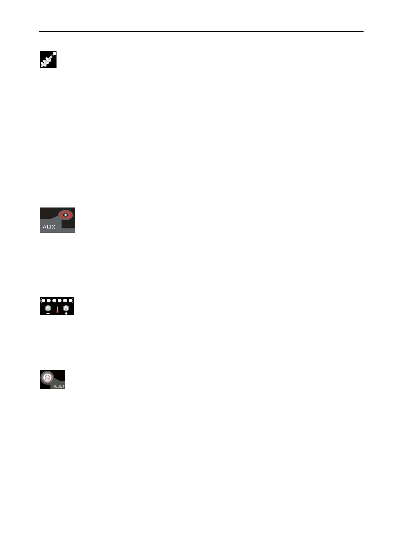
5.1.2 Fuel Feed Button
When the “Fuel Feed” button is pushed the stove will feed pellets continuously into the burn
pot for 90 seconds and then the ignition cycle will begin. The “Feed and Start” message will
appear.
Use this option when you start your stove for the first time in the season or when the stove has
run out of pellets, i.e. the hopper is empty. The auger will turn and then the stove will start
automatically an ignition cycle.
CAUTION: THIS FUNCTION CAN ONLY BE OPERATED WHEN THE STOVE IS IN “OFF”
POSITION. THE FUEL FEED SWITCH IS USED TO PRIME THE AUGER WHEN AUGER IS
EMPTY.
5.1.3 Convection Fan Speed Control
The convection fan can be adjusted to 9 predetermined speeds. By pressing on AUX, the
message FAN followed by a number between 1 to 9 will appear on the screen. It will be possible
to modify the blower speed by pressing on the + or the -. Take note that not all fan ranges are
available, but the speed of the convection blower is consistent with the requested burn rate.
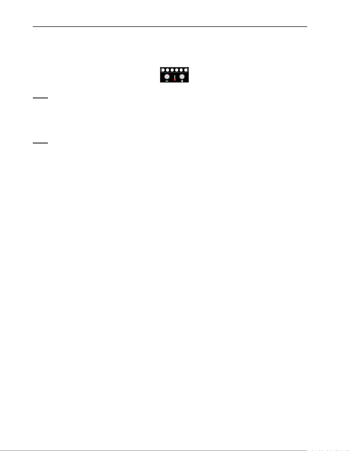
5.1.4 Heat Level
By pressing + or -, you can set the pellet feed rate and hence the heat output of your stove.
The levels of heat output will incrementally change and each LED indicates the level from 1 to
6.
5.1.5 Reset
The reset button has to be used to clear most warnings on the control panel and restart your
stove (see Section 6.6: Operating the Stove Using a Thermostat and Section 8.3: Main
Error Codes, Possible Causes and Solutions).
ECO-65R Installation and Operation Manual
33
5.2 Adjustments
5.2.1 Selecting the Combustion Level (Heat Rate)
The heat input of the stove varies between 9,000 BTU/h to 39,000 BTU/h. To change the
combustion level, select the + or – button when the stove is in function.
Note: Input range may vary according to the type of pellets being used.
Even though your stove can burn a large variety of wood pellets, we strongly recommend the
use of high-quality pellets to obtain maximum performance out of your stove (see Section
4.8.1: Proper Fuel).
Note: To obtain optimal results make sure the venting system, heat exchanger and
exhaust channels are cleaned before performing any setting changes.
5.2.2 Adjusting the Convection Fan Speed
You can adjust the stove’s convection fan speed for each combustion level selected. Thus, an
adjustment range is offered to reduce or increase air distribution in the room. Take note that
not all fan ranges are available, but the speed of the convection blower is consistent with the
requested burn rate. Therefore, if you use your stove in a lower combustion setting, you will
not be able to bring the fan to its maximum capacity. Conversely, for the higher combustion
settings, the lowest convection fan speed is blocked.
If overheating is detected, the convection fan speed will automatically go to the maximum
setting, an error code of F-160 will appear and the convection fan will operate at its highest
setting until the stove reaches a safe temperature. Once the stove reaches that temperature,
it will return to the previously selected convection fan selection.
ECO-65R Installation and Operation Manual
34
6 Stove Operation
6.1 First Startup
Before starting your stove, make sure that the burn pot, the baffle and the maintenance access
panels are properly installed. Make sure that the stove has been emptied of all tools and
accessories (see Section 2.3: Before Operating Your Stove). Also make sure that the venting
system is properly sealed, that all doors and hopper lid are closed. Make sure that the hopper
is full of pellets. Press the auger button .
If fire doesn’t start within 20 minutes, a warning code will appear. Refer to troubleshooting
section for more details.
WARNING: NEVER USE A GRATE OR OTHER MEANS OF SUPPORTING THE FUEL.
ONLY USE THE APPROVED STOVE BURN POT.
6.2 Everyday Startup
Before starting the stove, make sure there is enough pellets in the hopper and that the
recommended maintenance schedule has been followed (see Section 7.1.1: Recommended
maintenance schedule). Press the icon for either MANUEL or THERMOSTAT.
6.3 Running Out of Pellets
If your stove runs out of pellets, the fire will slowly go out; the convection fan will run until the
heat sensor on the exhaust fan reads 105°F. The cooling cycle will take a few minutes before
all other motors stops. When this temperature is reached, a warning message will appear
on the screen.
To restart the stove, wait until all components stop running (usually 10 minutes after the
warning message has been displayed). Press the button, refill the hopper, and press
the auger icon .
ECO-65R Installation and Operation Manual
35
6.4 Refueling
While the stove is running, you have up to 3 minutes to refill the hopper with pellets. Note that
opening the hopper lid will stop the auger from feeding pellets to the stove. If the hopper lid is
left open more than 3 minutes, the stove will stop and a warning code will appear on the
control panel. To restart the stove, close the lid, press the button, and then press the
to select either MANUAL or THERMOSTAT.
NOTE: Keep hopper lid closed at all times except when refueling. Do not overfill the
hopper.
6.5 Shutting Down Procedure
To turn your stove off, press the button on the control panel until the LED light is in the
OFF position. The cooling cycle will take a few minutes and the blowers will continue to function
while the stove is cooling down.
IMPORTANT: DO NOT DISCONNECT THE POWER CORD TO TURN OFF THE STOVE.
6.6 Operating the Stove Using a Thermostat
A thermostat may help you maintain a constant house temperature automatically (See
APPENDIX B: Thermostat installation (AC05558)). A Low voltage thermostat is required. A
fixed wall mount or handheld model can be used.
To use this mode, the button must be pushed to “Thermostat” upon starting the stove.
The heat setting is then selected using the selector “+ or –”. When set in thermostatic
mode, the stove will automatically run at the heat level selected until the set room temperature
is reached. When that occurs, the stove will switch to heat setting #1 (lowest) until the
thermostat calls for heat again. The convection blower will also slow to its lowest speed. When
the thermostat calls for heat again, the stove will increase its feed rate to match the heat setting
previously selected.
If the room temperature remains stable and the thermostat does not call for heat during at least
45 minutes, the stove will shut down. When the thermostat calls for heat again, the stove will
start an ignition cycle. Once the ignition cycle is completed, the stove will increase its feed rate
to match the heat setting selected.
6.6.1 Pilot Mode Selection
It is possible to change the setting of your unit such that if the thermostat does not call for heat
after 45 minutes, the unit will remain at the lowest heat setting (#1) but will not shut down (this
is the PILOT ON mode). The stove will remain at the lowest heat level until the thermostat calls
for heat again. It is also possible that the unit shuts down as soon as the thermostat stops
calling for heat. This mode is called “PILOT OFF”. If you prefer that your unit runs following one
ECO-65R Installation and Operation Manual
36
of these logics, you need to change the setting to PILOT ON or PILOT OFF by simultaneously
pressing the following two buttons on the PC Board for a couple of seconds:
and
Once you do that, the letters P, I, L, O, T, O, N will appear on the PC Board to let you know
that you are in the “PILOT ON” mode. By pressing again the two buttons, the letters P, I, L, O,
T, O, F, F will appear on the PC Board to let you know that you are in the “PILOT OFF” mode.
If you wish to go back to the default thermostatic mode (i.e. the unit shuts down after 45 minutes
if the thermostat does not call for heat), simply press the same two buttons again for a couple
of seconds. The letters P, I, L, O, T, A, U, T, O will appear on the PC Board to let you know
that you are in the “PILOT AUTO” mode.
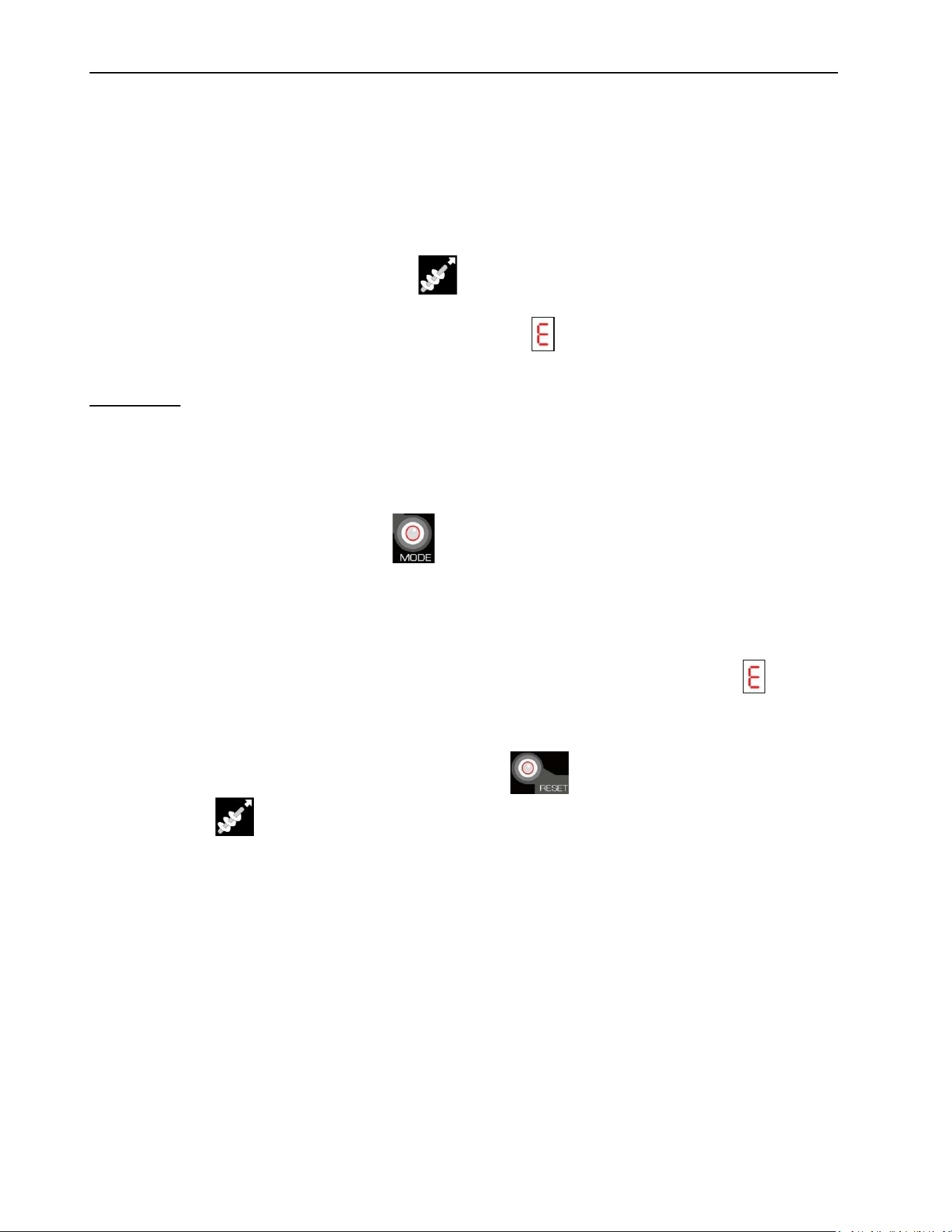
6.7 Signs of an Overheating Stove
Under normal conditions, the flame should have a bright yellow color and be very active, but
stable. If you see the flame getting lazy, very high and orange, it may be a sign that there is
something wrong. Usually, overheating issues are caused by too much restriction in the venting
system, a blocked heat exchanger, a lack of combustion air or a lack of maintenance.
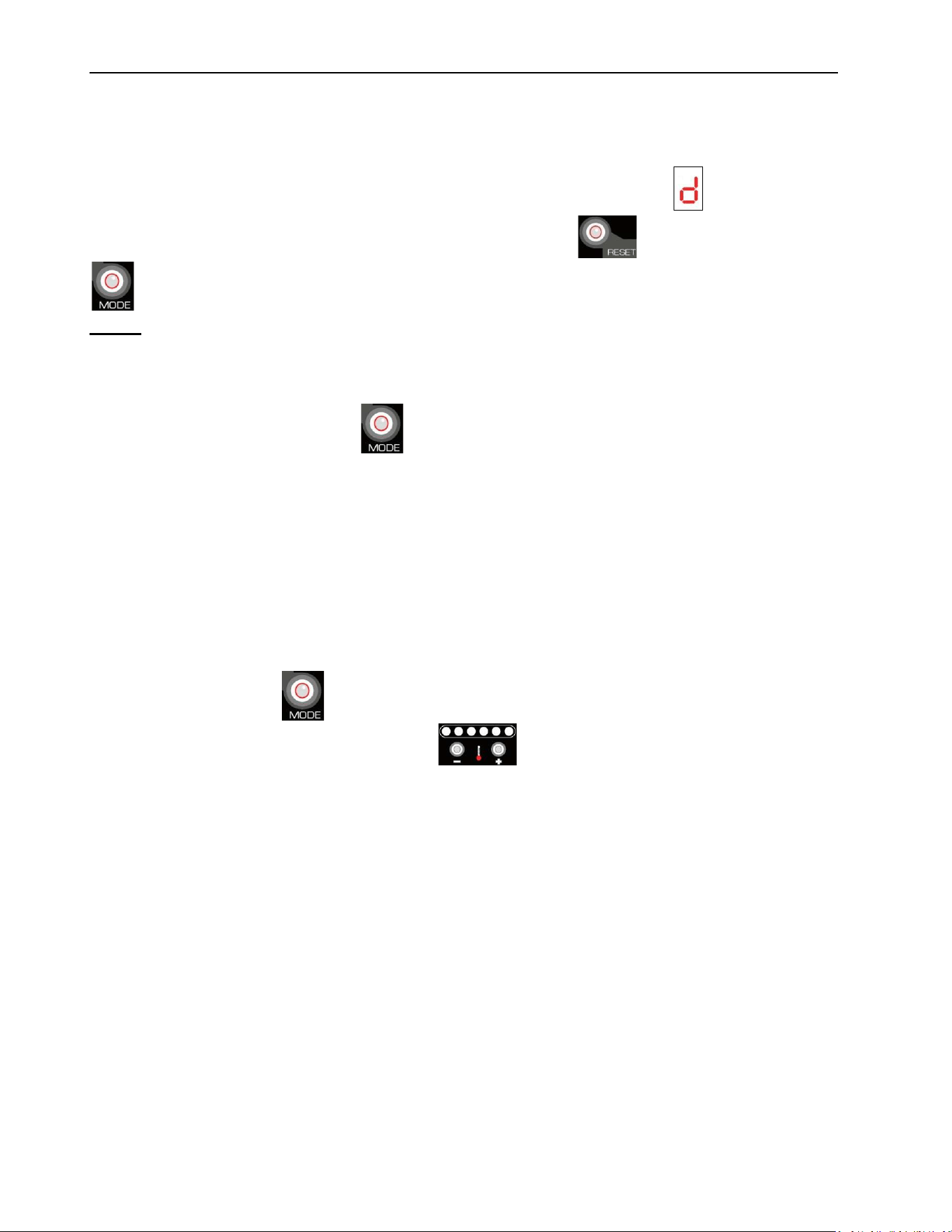
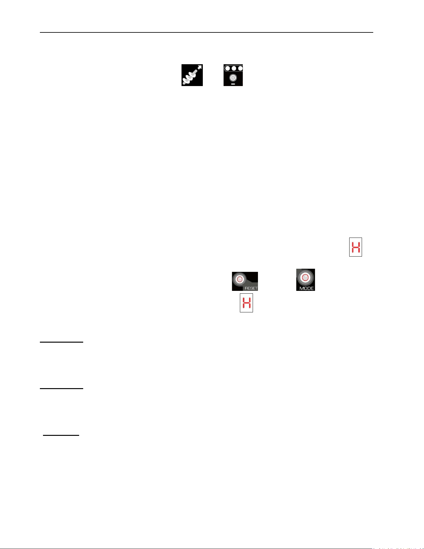
If this happens, your stove will become very hot. If the stove becomes too hot, an code
will appear on the control panel. Before starting the stove again make sure the recommended
maintenance has been done properly. Press the and the buttons and hold
simultaneously for 2 seconds to reset the stove. If an code occurs twice, call you dealer.
He will be able to give you some recommendations so this code won’t appear again.
WARNING: IF YOU CHOOSE A STOVE THAT IS TOO SMALL FOR YOUR HOUSE AND
YOU NEED TO OPERATE IT AT THE MAXIMUM SETTING FOR A LONG PERIOD OF TIME,
YOU MAY END UP OVERHEATING THE STOVE. THE STOVE AND ITS COMPONENTS
LIFE EXPECTANCY WILL BE REDUCED.
WARNING: IF ANY EXTERNAL PART OF THE STOVE BEGINS TO GLOW RED, THE
STOVE IS OVERHEATING. IMMEDIATELY TURN THE STOVE OFF. DO NOT UNPLUG IT
AND DO NOT OPEN THE DOOR. UNPLUGING THE STOVE WILL DISABLE ALL THE
SAFETY FEATURES OF THE STOVE.
DANGER: AN OVERHEATING STOVE MAY LEAD TO A HOUSE FIRE. EACH H CODE
SHOULD BE FOLLOWED BY A STOVE MAINTENANCE AND A VENTING SYSTEM
VERIFICATION.
ECO-65R Installation and Operation Manual
37
7 Maintenance
7.1 Stove Maintenance
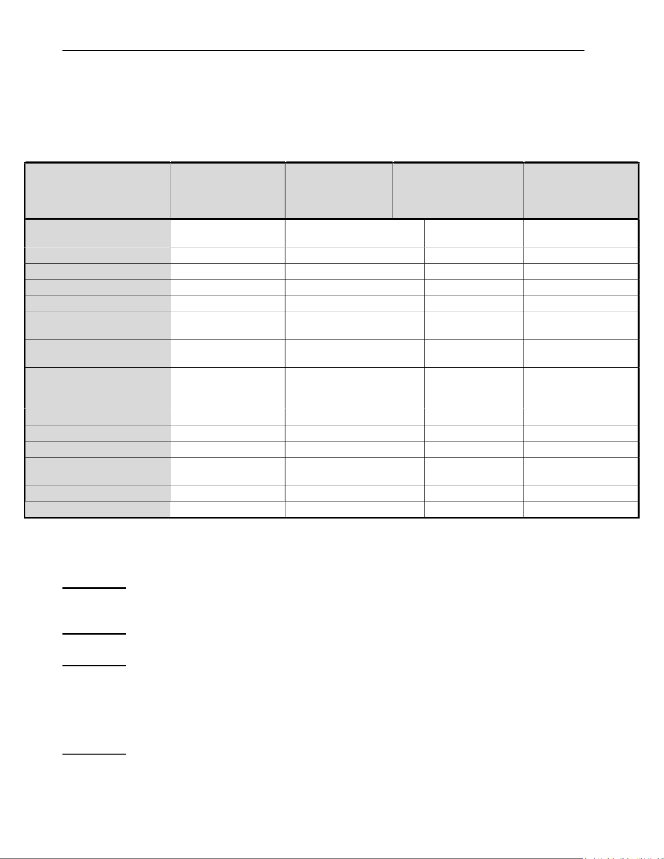
7.1.1 Recommended Maintenance Schedule
Use this as a guide when used under average conditions.
Components
Daily
or after
± 50 pounds
Weekly
or after
± 250 pounds
Twice a year
or after
± 1 ton
Annually
or
± 2 tons
Baffle
Activate the
cleaning rod
Scrape / Vacuum
Bottom air wash inlet
Vacuum
Burn Pot
Empty / Scrape
Scrape / Vacuum
Glass
Clean
Ash Drawer
Empty / Vacuum
Combustion Chamber
Vacuum
Vacuum /
Brush*
Heat Exchanger
Tubes
Brush
Scrape and
Vacuum*
Exhaust Channels
(through access
traps)
Vacuum*
Exhaust Blower
Vacuum*
Combustion Blower
Inspect*
Convection Blower
Vacuum*
Venting System
Inspect /
Sweep*
Sweep and Clean
Gaskets
Inspect
Hopper
Empty / Vacuum
*Cleaning frequency may vary depending on the type of fuel used. Fuel with higher ash content
will increase cleaning frequency. See Section 4.8.1: Proper Fuel for recommended
combustibles.
WARNING: FAILURE TO CLEAN AND MAINTAIN THIS STOVE AS INDICATED CAN
RESULT IN POOR PERFORMANCE AND SAFETY HAZARDS.
WARNING: NEVER CLEAN WHEN HOT.
WARNING: THE USE OF A DOMESTIC, CENTRAL OR COMMERCIAL VACUUM
CLEANER TO PERFORM THE MAINTENANCE OF YOUR PELLET STOVE IS NOT
RECOMMENDED. ASH PARTICLES MAY DAMAGE THE MOTORS OF THESES
APPLIANCES. FURTHERMORE, EMBERS THAT ARE STILL HOT MAY SET YOUR
VACCUM CLEANER’S CONTENT ON FIRE. THE USE OF AN ASH VACCUM CLEANER
IS HIGHLY RECOMMENDED.
WARNING: ASHES SHOULD BE PLACED IN A METAL CONTAINER WITH A TIGHT
FITTING LID. THE CLOSED METAL CONTAINER SHOULD BE PLACED ON A
NONCOMBUSTIBLE SURFACE, WELL AWAY FROM ALL COMBUSTIBLE MATERIALS,
ECO-65R Installation and Operation Manual
38
PENDING FINAL DISPOSAL. IF THE ASHES ARE DISPOSED OF BY BURIAL IN SOIL OR
OTHERWISE LOCALLY DISPERSED, THEY SHOULD BE RETAINED IN THE CLOSED
CONTAINER UNTIL ALL CINDERS HAVE BEEN THOROUGHLY COOLED.
7.1.2 Cleaning the Baffle, the Heat Exchanger and the Combustion Chamber
Cleaning the baffle must be done regularly (see Section 7.1.1: Recommended Maintenance
Schedule). Every day it is recommended to rotate the cleaning mechanism clockwise
vigorously. Rotate several times to remove accumulations of combustion residue from the
baffle.
Deep cleaning (scraping) is done at the same time as cleaning the exchanger.
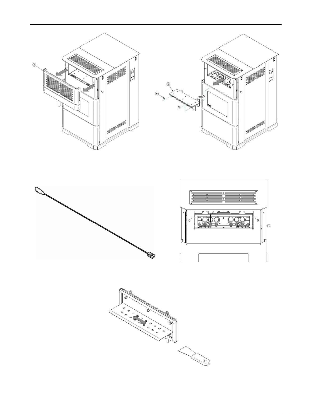
To clean the exchanger, you must first remove the decorative grill (A). Put your hands in the
side openings and give a quick pull towards you to release the grill. Unscrew the two wing nuts
(B) and remove the access panel (C) to the heat exchangers. Pay attention to the sealing
gasket when setting the access plate aside. Take the brush that was supplied with the stove
and insert it into each tube in a complete motion from top to bottom. IT IS IMPERATIVE TO
SLIDE THE BRUSH COMPLETY DOWN. IT WILL BE VERY DIFFICULT TO REMOVE THE
BRUSH IF IT IS STOPPED HALFWAY IN ONE OF THE TUBES. It is recommended to use
an ash vacuum to remove dust escaping from the tubes during the use of the brush.
ECO-65R Installation and Operation Manual
39
Using the provided sweeping rod, sweep up and down each exchanger. Make sure you go all
the way down to the bottom.
Using a scraper, remove all combustion residues that are blocking the baffle holes.
ECO-65R Installation and Operation Manual
40
Reinstall the access panel to the combustion chamber and tighten the wing nuts.
DO NOT USE PLIERS OR OTHER TOOLS TO TIGHTEN THE WING NUTS.
IT IS HIGHLY RECOMMENDED TO CLEAN THE EXHAUST CHANNEL (SEE SECTION
7.1.3: EXHAUST CHANNEL AND EXHAUST BLOWER MAINTENANCE) IMMEDIATLY
AFTER CLEANING THE HEAT EXCHANGER.
7.1.3 Exhaust Channel and Exhaust Blower Maintenance
Exhaust channels and the exhaust blower are located on the left-hand side of the stove. The
following procedure demonstrates how to perform inspection and cleaning:
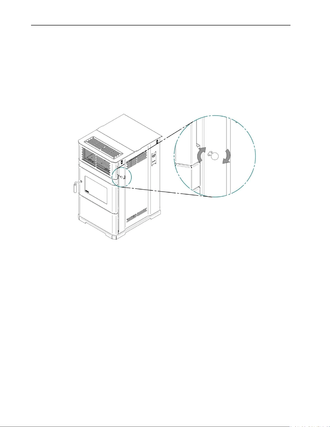
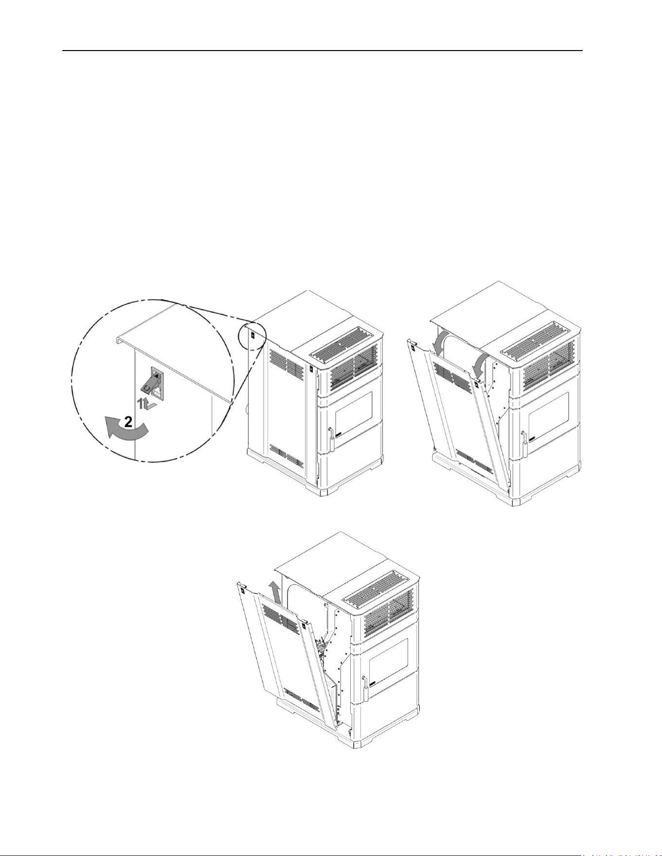
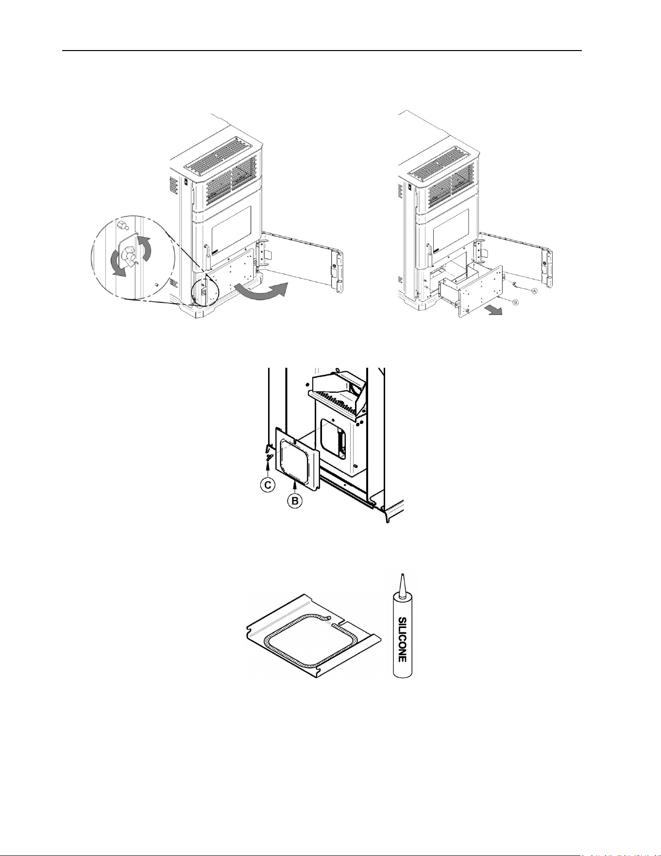
To access the exhaust channel, open the decorative panel located on the left side of the
stove facing it. Lift and turn the 2 latches, then rotate the panel and lift it up.
ECO-65R Installation and Operation Manual
41
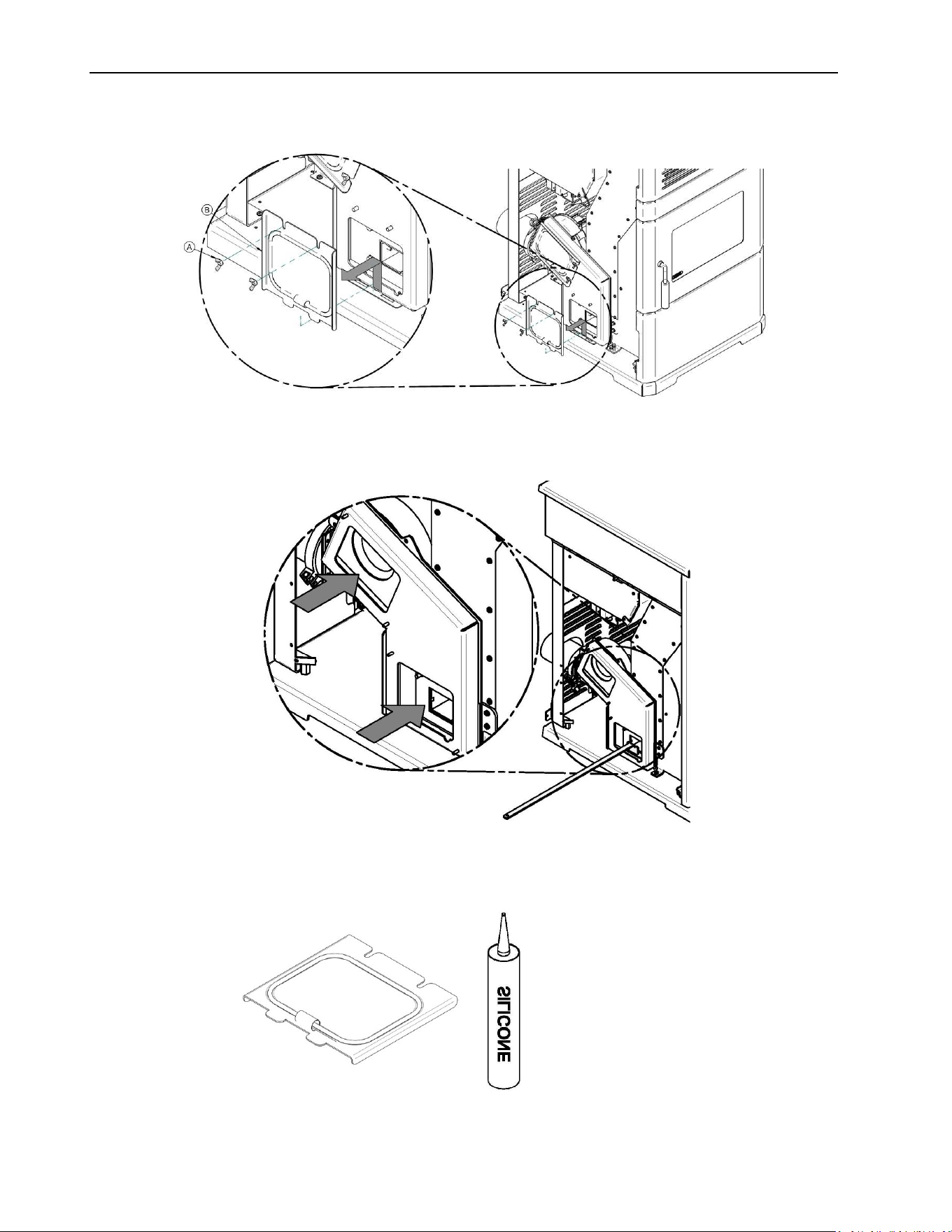
To remove the two access panels, you must unscrew the wing nuts (A) and then remove the
panels (B).
Locate the two openings. Clean any dirt or ash buildup from exhaust channels using the scraper
supplied with the stove. Use an ash vacuum to complete the cleaning.
Make sure that the gaskets are still in good condition, replace them if needed. (3/16’’ black
round gasket, AC06815)
ECO-65R Installation and Operation Manual
42
7.1.4 Cleaning the Burn Pot
The burn pot must remain clean and the holes should not be obstructed by combustion residues
(ashes or clinkers).
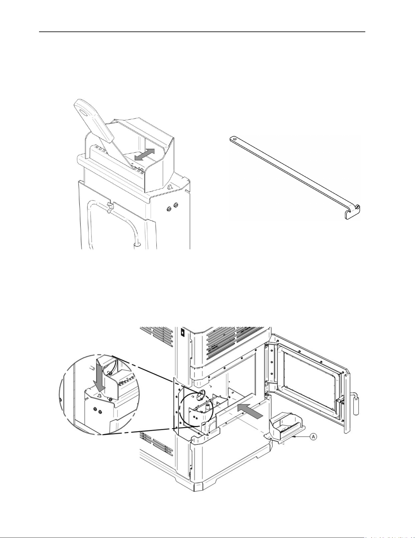
1. Clean the burn pot using the scraper provided with the stove or a smaller one.
2. The burn pot (A) simply sits onto the air intake channel. You must lift to remove it from the
stove. Two small pins guide the burn pot in place. Make sure that the burn pot is well in
place before turning on the stove (as shown in the diagram).
ECO-65R Installation and Operation Manual
43
3. If necessary, clean the air intake channel. To reach the air intake channel clean out trap,
open the ash drawer access door and remove the ash drawer (A).
4. Unscrew the wing nut (C) to open the clean out trap (B). Vacuum the combustion residues.
Verify that the clean out trap gasket is still in good condition, replace it if needed (3/16’’ black
round gasket, AC06815).
ECO-65R Installation and Operation Manual
44
7.1.5 Ash Removal
1. To empty the ash drawer (A) of its contents, open the ash drawer access door. Remove the
two wing nuts and take out the ash drawer.
2. Empty the ash drawer, vacuum around the drawer and at the bottom of the combustion
chamber.
WARNING: ASH PAN MUST BE IN PLACE AND THE ASH PAN ACCESS DOOR MUST BE
KEPT CLOSED AT ALL TIMES WHEN THE STOVE IS IN USE.
7.1.6 Cleaning the Air Wash System
Vacuum the ashes that may have accumulated into the air wash system inlet between the
bottom glass retainer and the glass. This will allow an optimum air flow along the inside portion
of the glass and prevents the glass from sooting.

ECO-65R Installation and Operation Manual
45
7.1.7 Glass Car
Clean door glass when necessary. The use of a stove glass cleaner is recommended. Regular
household glass cleaners will not remove creosote properly.
WARNING: NEVER USE ABRASIVE CLEANERS ON THE GLASS OR ON ANY PLATED
PART.
WARNING: DO NOT CLEAN THE GLASS WHILE IT’S HOT.
WARNING: DO NOT FORCE, STRIKE OR ADOPT ANY BEHAVIOUR THAT COULD
WEAKEN THE GLASS DOOR.
WARNING: DO NOT OPERATE THE STOVE WITH THE GLASS REMOVED, CRACKED OR
BROKEN.
7.1.8 Replacement of Broken Door Glass
Carefully remove any loose pieces of glass from the doorframe. Dispose of all broken glass
properly.
A broken glass must be replaced with an identical ROBAX (ceramic glass) 5 mm thick with the
dimensions: 9" 3/8’’ x 14" 21/32’’. Refer to Section 14: Exploded View and Replacement
Parts.
WARNING: ALWAYS WEAR SUITABLE GLOVES WHILE HANDLING BROKEN GLASS.
WARNING: REPLACEMENT GLASS SHOULD ONLY BE PURCHASED FROM AN
AUTHORIZED DEALER (SEE SECTION 14: EXPLODED VIEW AND REPLACEMENT
PARTS). TEMPERED GLASS OR ORDINARY GLASS WILL NOT WITHSTAND THE HIGH
TEMPERATURES OF THE STOVE.
WARNING: IF YOU HAVE TO CHANGE THE DOOR GLASS, MAKE SURE YOU INSTALL
THE NEW GASKETS AT THE SAME PLACE AS THE ORIGINAL IN ORDER TO KEEP THE
AIRWASH WORKING PROPERLY.
7.1.9 Door Gasket Maintenance
It is important to maintain the door gasket in good condition. After a while, the gasket will wear
and compress; adjusting the door may then be required. If the door adjustment is not sufficient,
replace the door gasket with a genuine part. If the stove door is not properly sealed, it will be
difficult to keep the door glass clean and combustion gases may leak into the room.
7.1.10 Door Adjustment
In order for your stove to burn at its best efficiency, the door must provide a perfect seal with
the firebox. Therefore, the gasket should be inspected periodically making sure to obtain an
airtight fit. Air tightness can be improved with a simple latch mechanism adjustment. To adjust:
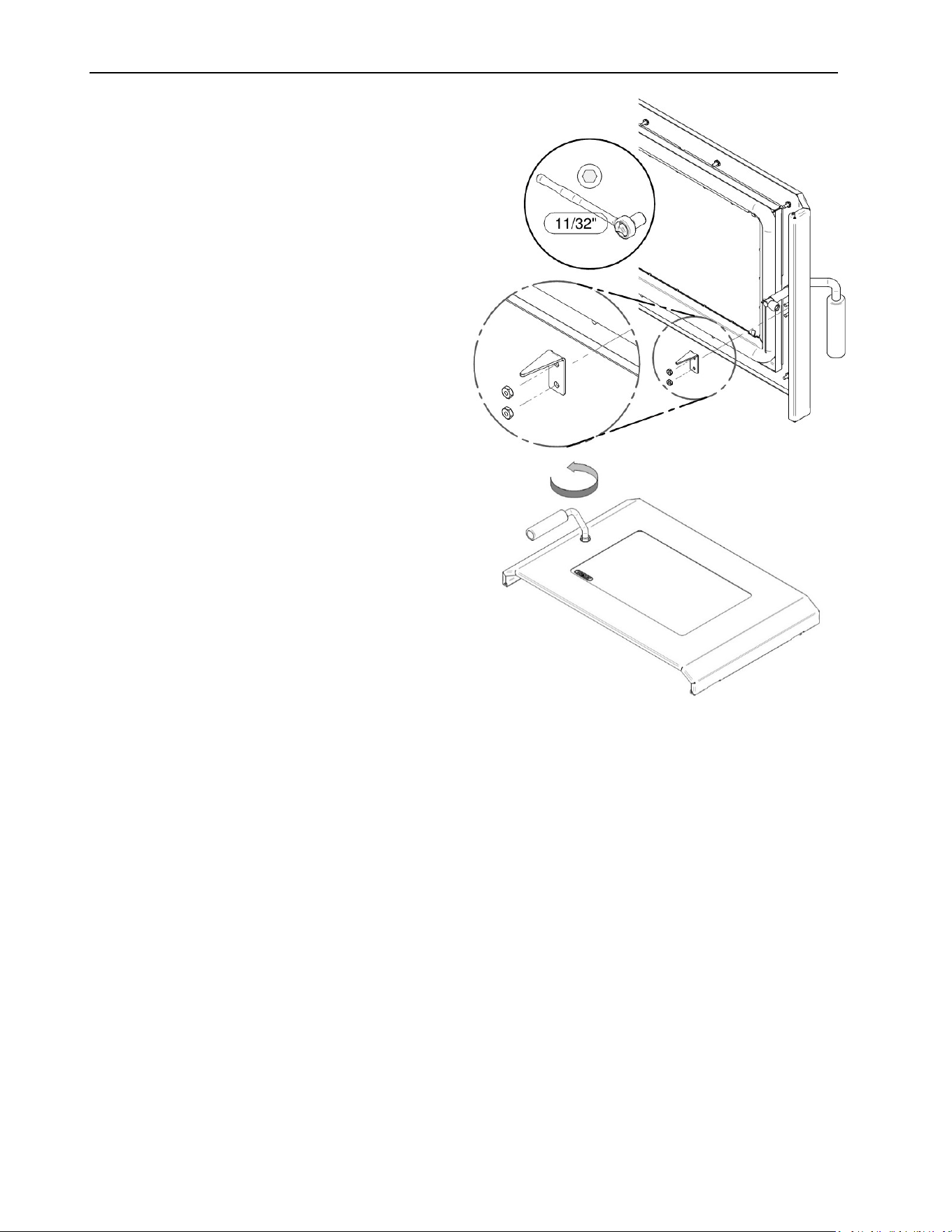
ECO-65R Installation and Operation Manual
46
Remove the handle stop, by
unscrewing the two 11/32’’ nuts.
Then unscrew the handle one turn
to increase the pressure between
the door frame and the firebox.
Reinstall the handle stop next.
7.1.11 Gasket replacement
It is important to replace the gasket with another having the same diameter and density to
maintain a good seal.
1. Remove the old gasket. Use a screwdriver to scrape the old gasket adhesive from the
groove.
2. Apply a bead of approximately 3/16" (5 mm) of high temperature silicone in the groove. The
gasket must not be stretched during installation.
3. Leave about ½" long of the gasket when cutting and press the end into the groove. Tuck
any loose fibers under the gasket and into the silicone.
4. Close the door or trap. Do not use the pellet stove for 24 hours.

ECO-65R Installation and Operation Manual
47
7.2 Venting System Maintenance
Establish a routine for the fuel, wood burner and firing technique. Check daily for creosote
build-up until experience shows how often you need to clean to be safe. Be aware that the
hotter the fire the less creosote is deposited, and weekly cleaning may be necessary in mild
weather even though monthly cleaning may be enough in the coldest months. Contact your
local municipal or provincial fire authority for information on how to handle a chimney fire. Have
a clearly understood plan to handle a chimney fire.
CAUTION: REGULARLY EXAMINE THE VENTING SYSTEM, THE JOINTS, AND THE
SEALING TRIMS TO ENSURE THAT THE SMOKE AND THE COMBUSTION GASES ARE
NOT DRAWN BY THE CONVECTION BLOWER.
The most efficient method to sweep the venting system is by using a 4'' pellet brush depending
on your installation. Brush downwards so ash, soot and creosote residues will come off the
inner surface and fall at the bottom of the clean out tee where they can be easily removed. The
venting system must be in good condition and kept clean.
WARNING: IF A SIGNIFICANT LAYER OF CREOSOTE HAS ACCUMULATED (3MM / 1/8”
OR MORE), IT MUST BE REMOVED IMMEDIATELY TO ELIMINATE THE RISK OF A
CHIMNEY FIRE.
7.2.1 Facing a Chimney Fire
Regular chimney maintenance and inspection can prevent chimney fires. If you have a chimney
fire, follow these steps:
1. Evacuate family members and animals from the building, then call the fire department.
2. Turn off the unit. Do not unplug it!
3. If possible, use a chemical fire extinguisher, baking soda or sand to control the fire. Do not
use water, as this may cause hazardous vapor explosions.
4. Do not use the stove until the vent system and the stove have been inspected by a qualified
chimney sweeper or fire inspector.
CAUTION: CLEANOUT OF THE STOVE AND THE VENTING SYSTEM IS ESPECIALLY
IMPORTANT AT THE END OF THE HEATING SEASON TO MINIMIZE CORROSION
DURING THE SUMMER MONTHS, CAUSED BY ACCUMULATED ASH.
7.2.2 Soot and Fly Ash
The combustion products contain small particles of fly ash. Fly ash can accumulate especially
in horizontal sections of exhaust pipe and restrict the flow of combustion gases. Incomplete
combustion, produced when igniting, shut down or misuse of the stove will cause some soot
formation which can accumulate in venting system. The venting system must be inspected
at least twice a year to determine if cleaning is necessary
.

ECO-65R Installation and Operation Manual
48
8 Troubleshooting
When you have issues with your stove, your first reaction may be to call technical support. This
section will help you save time and money by enabling you to solve simple problems by
yourself.
Most common problems are generally caused by the following five factors:
1. Wrong operation or lack of maintenance.
2. Bad installation.
3. Poor quality combustible.
4. Component failure.
5. Factory defect.
The stove is equipped with a pc board that allows the stove to diagnose itself. It is thus
important not to unplug the stove if there is an issue with it. First, because unplugging the stove
will disable all the security features of the stove, and second, because you will not be able to
see the error code given by the stove to understand what the problem is. It is thus important to
read carefully this section before calling technical support.
The following sections will help you test each component individually and will also give you
many tips in how to solve any problems related to a specific error code.
NOTE: IF YOU NEED TO CONTACT YOUR DEALER OR TECHNICAL SUPPORT, MAKE
SURE TO HAVE THE MODEL OF YOUR STOVE AND THE SERIAL NUMBER ON HAND.
(THEY CAN BE FOUND ON THE CERTIFICATION LABEL INSIDE THE HOPPER LID).
8.1 Electric Components List
- Electronic components (low power rated)
o F160 (security heat sensor)
o L-250A (security heat sensor)
o RTD (temperature sensor)
o Pressure switch (security sensor)
o Hopper switch (mechanical security sensor)
o Thermostat (temperature regulator device)
- Electrical components (high power rated)
o Igniter (heater)
o Combustion blower (will feed fire with fresh air)
o Convection blower (will send hot air into the room)
o Exhaust blower (will extract combustion gas out of the stove)
o Auger motor 1 (located under the hopper)
o Auger motor 2 (will feed the fire with pellets)
WARNING: RISK OF ELECTRICAL SHOCK. IF YOU NEED TO MANUALLY TEST,
MANIPULATE OR REPLACE ANY COMPONENTS, THE STOVE NEEDS TO BE
DISCONNECTED FROM THE WALL OUTLET.
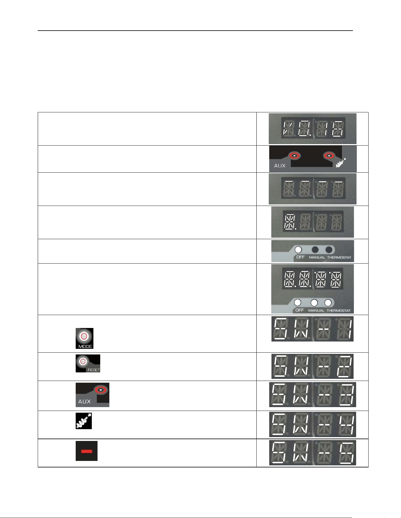
ECO-65R Installation and Operation Manual
49
8.2 Testing a Component
If you suspect that an electrical component to be defective, you can test it by following the
procedure given below.
Note that you will be able to test only components when the stove is OFF and that all the
components are no more in function. (Take note that the software versions given below are an
example only and may not reflect the actual software versions of your stove.)
Connect the stove and read the version of software included
in the control board
In order to access the test mode, press both of these control
keys simultaneously.
Each segment of each section of the display will turn on in
sequence. Push any control key to proceed.
Each complete section of the display will turn on in sequence.
Push any control key to proceed.
Each LED lights up in sequence (from « OFF » to « #6 feed
rate ». Push any control key to proceed.
Complete display and all LEDs light up simultaneously. Push
any control key to proceed.
Control Key Tests
Push the control key to proceed.
Push the control key to proceed.
Push the control key to proceed.
Push the control key to proceed.
Push the control key to proceed.
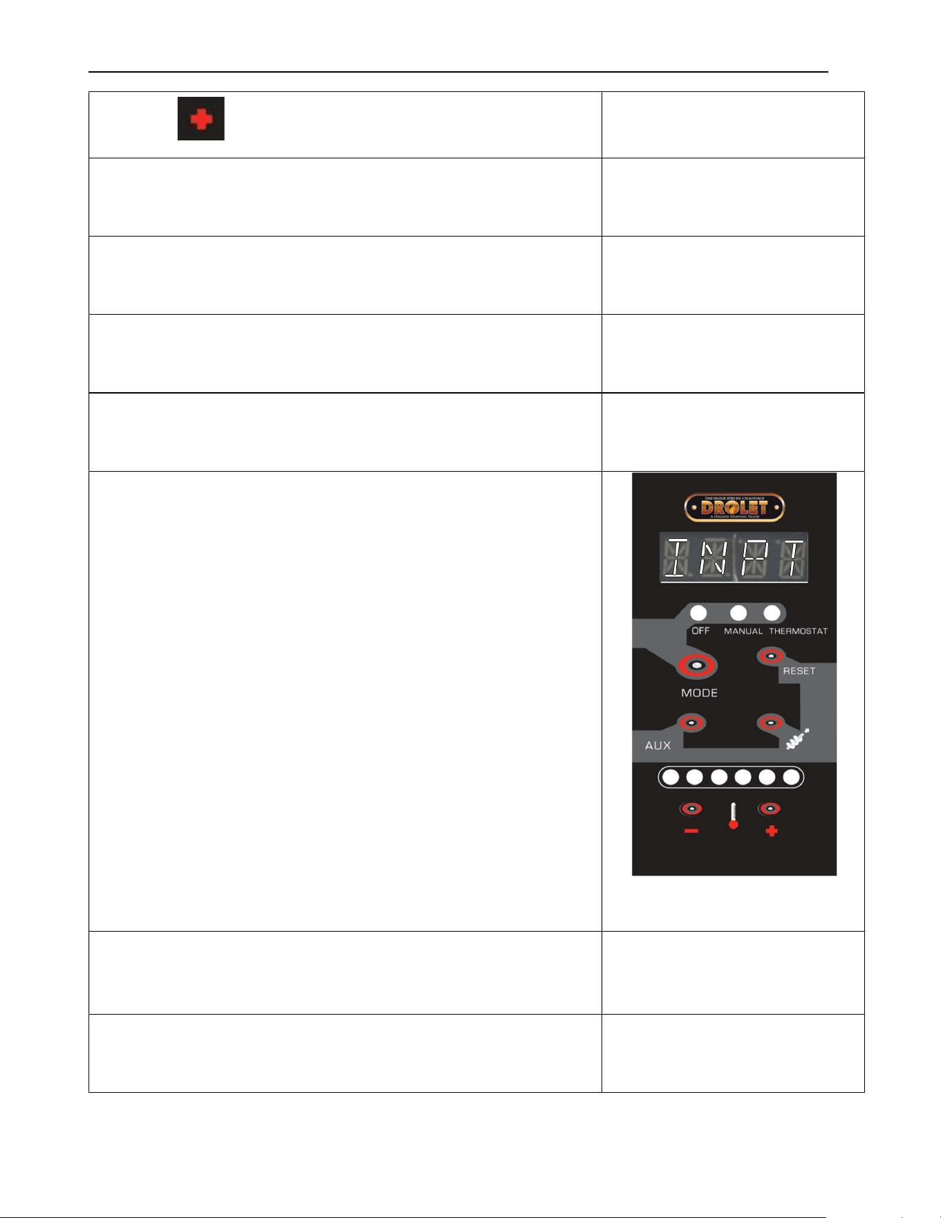
ECO-65R Installation and Operation Manual
50
Push the control key to proceed.
The frequency of the power source is displayed. Push any
control key to proceed.
The voltage of the power source is displayed. Push any
control key to proceed.
Displays if polarity is good (POLP)
If polarity is reversed (POLF). Push any control key to
proceed.
The version of software included in the control board is
displayed. Push any control key to proceed.
Displays the status of different components.
OFF LED: Pressure switch
MANUAL LED: Hopper switch
THERMOSTAT LED: Wall thermostat
FEED RATE 1: (non operative)
FEED RATE 2: F160
FEED RATE 3: L250
FEED RATE 4: (non operative)
FEED RATE 5: auger # 2 fuse
FEED RATE 6: igniter fuse
Note:
- LED ON = open circuit
- LED ON = blown fuse
- LED OFF = close circuit
- LED OFF = fuse good
Push any
control key to proceed.
SPARE output testing section.
(NOT OPERATIVE ON THIS VERSION)
Push any control key to proceed.
« Zero current » test used by the control board. Push any
control key to proceed.
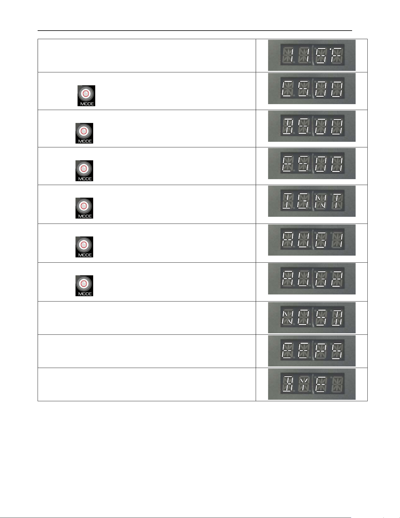
ECO-65R Installation and Operation Manual
51
Displays the temperature read by the flue gas temperature
probe. Push any control key to proceed.
Convection blower test.
Push the control key to proceed.
Combustion blower test.
Push the control key to proceed.
Exhaust blower test.
Push the control key to proceed.
Ignitor test.
Push the control key to proceed.
Auger# 1 test.
Push the control key to proceed.
Auger#2 test.
Push the control key to proceed.
Validate the absence of an SD card in the reprogramming
port. Push any control key to proceed.
Validate that the control board’s EEPROM is functional. Push
any control key to proceed.
End of the test mode sequence.
The stove turns on by itself.
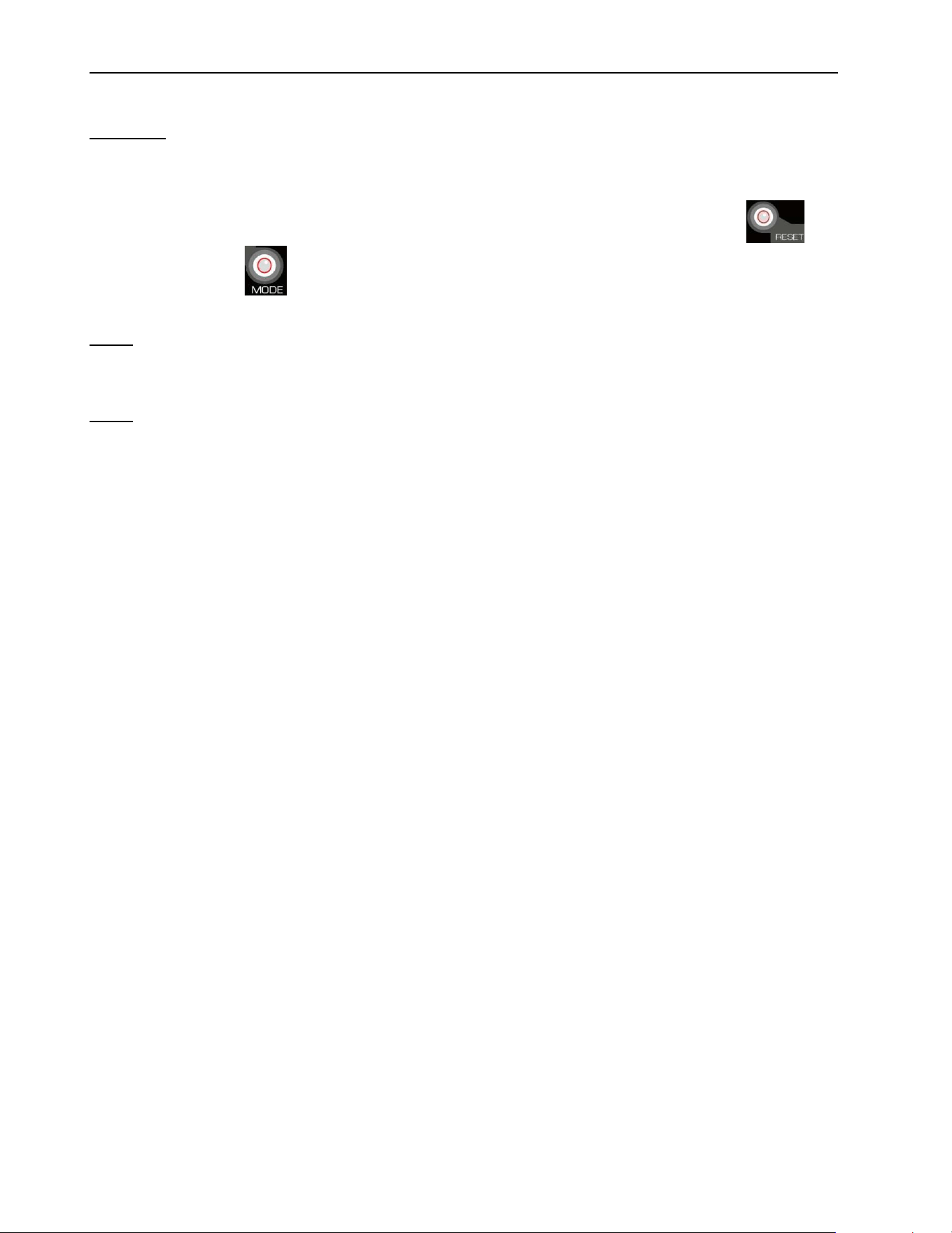
ECO-65R Installation and Operation Manual
52
8.3 Main Error Codes, Possible Causes and Solutions
WARNING: RISK OF ELECTRICAL SHOCK. IF YOU NEED TO MANUALLY TEST, MANIPULATE OR
REPLACE ANY COMPONENTS, THE STOVE NEEDS TO BE DISCONNECTED FROM THE WALL OUTLET.
This section contains main error codes, possible causes and many suggestions to guide you
in resolving them. After giving an error code, your stove will shut down by itself and start a cool
down cycle. If you want to start your stove again, you will need to press on the button
and then on the button. Your stove will only restart when the cool down cycle is
completed.
NOTE: IF, AFTER PERFORMING ALL THE POSSIBLE SOLUTIONS MENTIONED IN THE FOLLOWING
SECTION, YOU ARE STILL EXPERIENCING PROBLEMS WITH YOUR STOVE, CALL YOUR LOCAL
DEALER OR A SERVICE TECHNICIAN AT 1-877-356-6663. YOU CAN ALSO WRITE AN EMAIL TO tech@sbi-
international.com. ALL EMAILS ARE ANSWERED WITHIN A 24H DELAY.
NOTE: IF YOU NEED TO CONTACT YOUR DEALER OR TECHNICAL SUPPORT, MAKE SURE TO HAVE
THE MODEL OF YOUR STOVE AND THE SERIAL NUMBER ON HAND. (THEY CAN BE FOUND ON THE
CERTIFICATION LABEL INSIDE THE HOPPER LID).
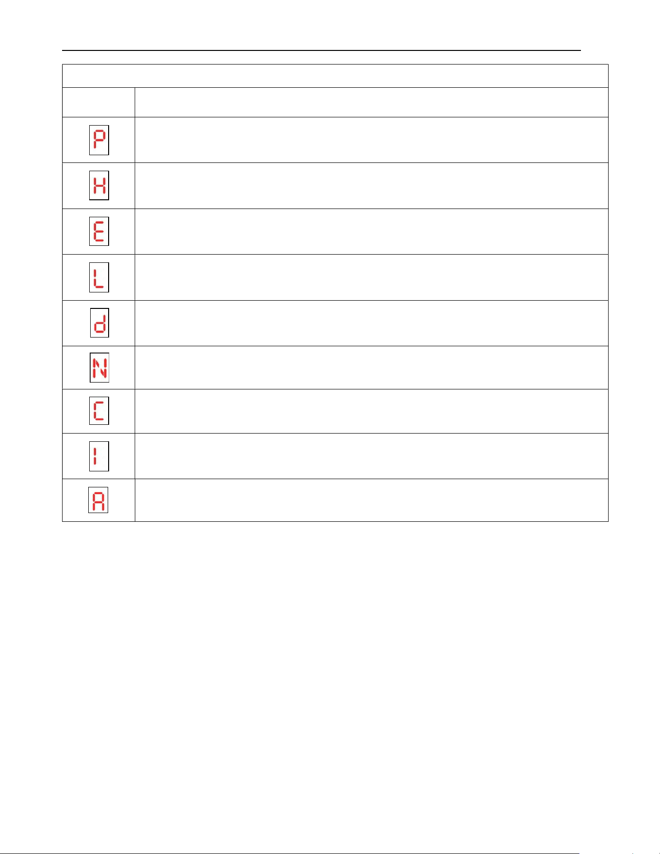
ECO-65R Installation and Operation Manual
53
ALARM CODES CHART
MESSAGE
CORRESPONDING WARNING
Pressure switch warning.
Warning caused by the automatic L-250 sensors: it is located over the pellet
housing.
Hopper is empty
Lighting warning.
Hopper lid stayed open more than 3 minutes.
Inverted polarity in power outlet.
Power outage
Igniter fuse is blown
Auger fuse has blown
ECO-65R Installation and Operation Manual
54
8.3.1 P Code
STOVE SHUTS OFF AND APPEARS ON CONTROL BOARD
Possible Causes:
Possible Remedies: (Unplug stove first when
possible)
1. Pressure tap (located on the
exhaust blower) is blocked.
Pull off the air hose from the exhaust blower pressure
tap and from the negative (white) pressure switch tap.
WARNING: THE TUBE MUST ABSOLUTELY BE
DISCONNECTED FROM THE PRESSURE SWITCH
AS TO NOT DAMAGE IT.. Blow in the air tube. If air
flows freely, the hose is fine. If air does not flow
through the hose, use a thin wire to clear the blockage.
2. The flue is blocked or needs
cleaning.
One of the following components is obstructed or
blocked by ashes of by a foreign object; air intake
shutter, combustion blower, burn pot, heat exchangers
and exhaust channels, exhaust blower and or venting
system. Refer to the maintenance section.
3. The flue is not properly installed.
Make sure the venting system meets the criteria in the
installation section of this manual as well as the
venting system manufacturer’s instructions.
4. A back draft occurred inside the
flue.
This can occur on a very windy day or if your venting
system does not have a proper termination.
5. The pressure switch wire
connections are faulty.
Make sure that the pressure switch wires and
connections are not grounded or loose. Replace or
replug wires if necessary.
6. The pressure switch hose is
disconnected.
Make sure the pressure switch hose is well installed on
the exhaust blower pressure tap and on the white (-)
pressure switch tap. If not, reinstall it.
7. The exhaust or combustion
blower failed.
See Section 8.2: Testing a Component and test the
exhaust and the combustion blowers independently. If
one of them does not work, make sure there is power
and that blowers are well connected. If they still don’t
work, check fuse F4 and F5 on the control board. A
defective fuse will be darkened or will have a broken
filament. If the fuses are good, the combustion or
exhaust blower is probably defective. Replace the
faulty part.
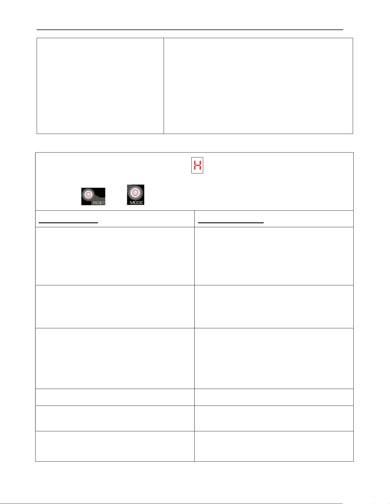
ECO-65R Installation and Operation Manual
55
8. Pressure switch is defective
(very rare).
Even though this situation is highly unlikely, it’s
possible the pressure switch is defective. To test the
airflow pressure switch, you need to disconnect the air
hose from the blower casing. With the other end still
attached to the switch, very gently suck on the loose
end of the hose (you may want to completely
disconnect the hose from the stove and the switch first
and make sure it is clear). If you hear a « click », the
switch is working. Be careful: too much suction can
damage the switch.
8.3.2 H Code
STOVE STOPS FEEDING PELLETS AND APPEARS ON THE CONTROL BOARD.
BEFORE RESETTING TAKE CARE IN READING THE POSSIBLE CAUSES AND THEN
PRESS ON AND AT THE SAME TIME FOR 2 SECONDS.
Possible Cause: Possible Remedy:
1. Inadequate fuel is used.
Remove the burn pot, make sure that all
openings are clear and check that no ash has
filled the tube around the igniter. Refer to the
maintenance section. Also, make sure that
the recommended fuel is used (see Section
4.8.1: Proper Fuel).
2. The flue is not properly installed. Make sure the venting system meets the
criteria in the Section 4: Venting System as
well as the venting system manufacturer’s
instructions.
3. The flue is blocked or needs cleaning. One of the following components is
obstructed or blocked; air intake shutter,
combustion blower, burn pot, heat
exchangers and channels, exhaust blower
and or venting system. Refer to Section 7:
Maintenance.
4. The stove needs maintenance. Refer to Section 7: Maintenance.
5. The burn pot is not installed properly. Make sure the burn pot is installed correctly
(see Section 7.1.4: Cleaning the Burn Pot).
6. The baffle is not installed properly or holes
may be blocked.
Make sure the baffle is well installed and the
lock is in place. Make sure the holes are clear
(see
Section
7
.1.2: Cleaning the Baffle, the
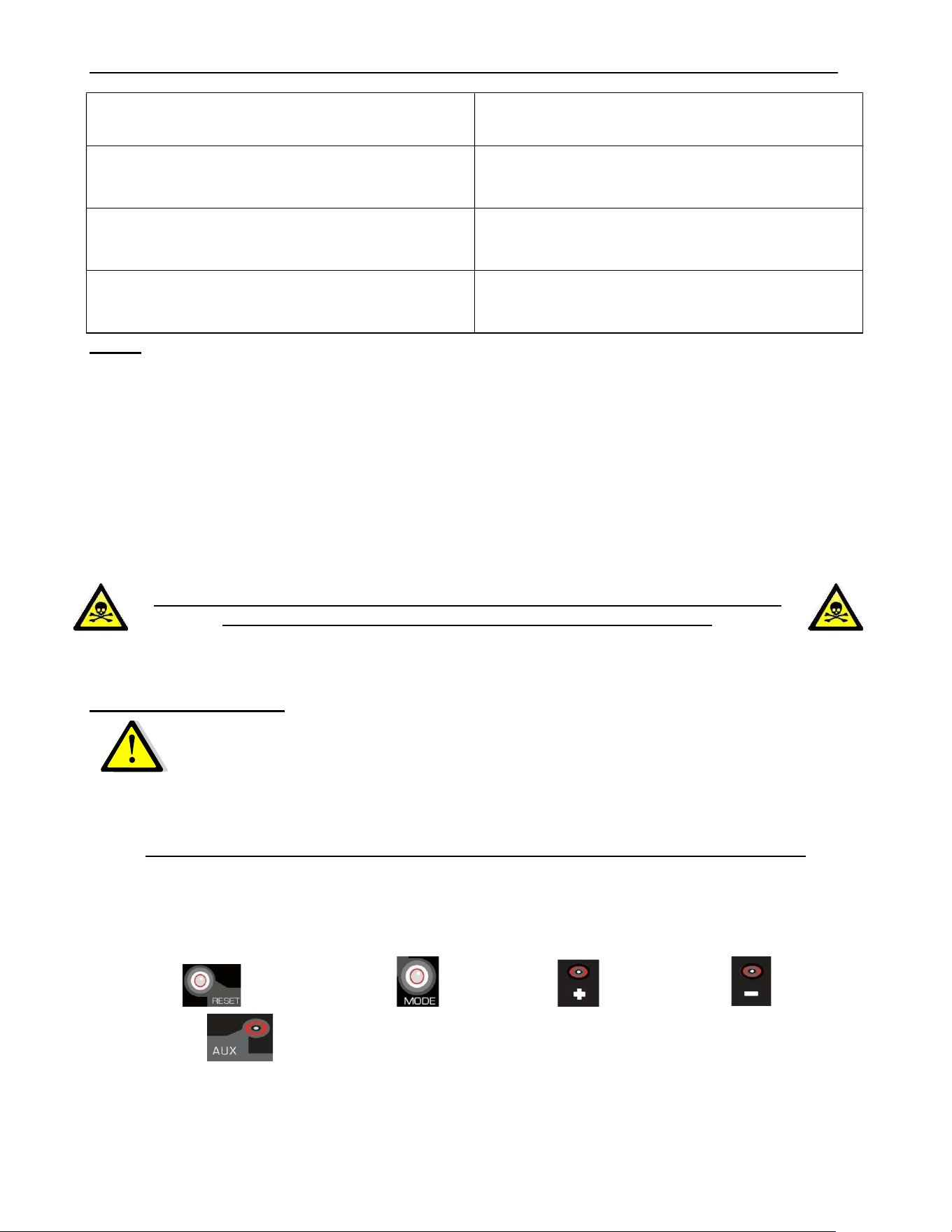
ECO-65R Installation and Operation Manual
56
Heat Exchanger and the Combustion
Chamber).
7. The convection blower is defective. See Section 8.2: Testing a Component and
test the convection blower.
8. he combustion blower needs cleaning. Carefully clean blower housing and make
sure blower louvers are not blocked.
9. The exhaust blower is defective. See Section 8.2: Testing a Component and
test the exhaust blower.
NOTE: IF THE CODE APPEARS MORE THAN THREE TIMES, THE ERROR CODE WILL
LOCK ITSELF UP.
THIS PELLET STOVE IS EQUIPED WITH MULTIPLE DEVICES TO ENSURE YOUR
SAFETY. IF A WARNING ERROR CODE STOPS YOUR STOVE ON SEVERAL
OCCASIONS, IT IS MORE THAN LIKELY THAT THE STOVE DOES NOT EXHAUST
PROPERLY.
COMPLETE the stove maintenance as described in this manual before
resetting the electronic board displaying an error code.
For an Overheat Code
•
Service the stove COMPLETELY as described in this manual. See
section 7: Maintenance
• Verify the complete venting system.
FOLLOW THESE INSTRUCTIONS ONCE THE MAINTENANCE COMPLETED
Press on the following buttons in the sequence given (one button at a time).
« Reset » then « Mode » then « + » then « - » and hold
« Auxiliary » for 3 seconds. The system will reset.
ECO-65R Installation and Operation Manual
57
8.3.3 E Code
STOVE SHUTS OFF AND DISPLAYS WARNING CODE
Possible Causes:
Possible Remedies: (Unplug stove first when
possible)
1. The stove ran out of pellets. Refill the hopper. Erase the error code and press the
auger button (see Section 5.1.2: Fuel Feed
Button).
2. The burn potholes are blocked. Remove the burn pot and clean it thoroughly.
3. The air intake, the inner parts of the
combustion chamber or the venting
system is partly blocked.
Follow instructions in the Maintenance section.
4. One or both auger motors are
jammed or have failed.
See Section 8.2: Testing a Component and test
auger motors independently. If one of the motors is
not running check if motor is defective or if the auger
is jammed. Make sure that the hopper lid is closed.
If the auger motor seems defective, check to make
sure that electrical connections are not loose and
check the fuses F2 and F6 on the control board. A
defective fuse will be darkened or will have a broken
filament. If the fuses are good, the auger motor may
be jammed by an object.
If the auger is jammed, remove it from its housing
(see drawing below). NOTE: IF THE HOPPER
AUGER MOTOR FAILED OR THE HOPPER
AUGER IS JAMMED, TO AVOID PELLET
SPILLAGE, EMPTY THE HOPPER OF ITS
CONTENTS BEFORE EXECUTING THE
FOLLOWING TESTS. Disconnect the motor and
then remove the four screws on the steel plate that
holds the auger shaft to the auger housing. To have
an easier access, remove the rear panel for an
easier access. Pull out the auger from the housing.
Once the auger has been removed, make sure the
auger is straight, that the surface is not damaged
and there are no burrs, or broken welds. Remove
any foreign material that may have caused the jam.
Inspect the auger housing for signs of damage such
as burrs, rough spots, or grooves cut into the metal
that could have caused a jam. Clean the auger
housing thoroughly to remove all pellet dust.

ECO-65R Installation and Operation Manual
58
5. The flue gas temperature probe is
defective.
The probe is a heat sensor located on the exhaust
channel. Its function is to tell the control board that
the stove has ignited properly by measuring the heat
at the exhaust. The pellet stove will not start feeding
pellets at the desired heat setting until it has
received a signal from the temperature probe. If the
temperature probe is faulty, the unit will stop after
the ignition cycle. To display the temperature
reading from the temperature probe press and hold
the + and auger buttons for 3 seconds. Confirm that
the value displayed is equal to the ambient
temperature in the room where the appliance is
installed. If this is the case, turn on the stove and
check the same temperature display. If after 10
minutes, the value has not increased despite the
unit is in operation this means that the temperature
probe is disconnected or defective. If the
temperature rises, the problem may be with the feed
rate or pilot mode. Depending on many factors
(ambient temperature, pellet quality, etc.) the heat
produced by the stove may not be sufficient to keep
the exhaust temperature high enough. To resolve
the situation, increase feed rate (see Section 5.2.1:
Selecting the Combustion Level (Heat Rate)).
NOTE: IF THE HOPPER AUGER MOTOR FAILED OR THE HOPPER AUGER IS JAMMED,
TO AVOID PELLET SPILLAGE, EMPTY THE HOPPER OF ITS CONTENTS BEFORE
EXECUTING THE FOLLOWING TESTS.
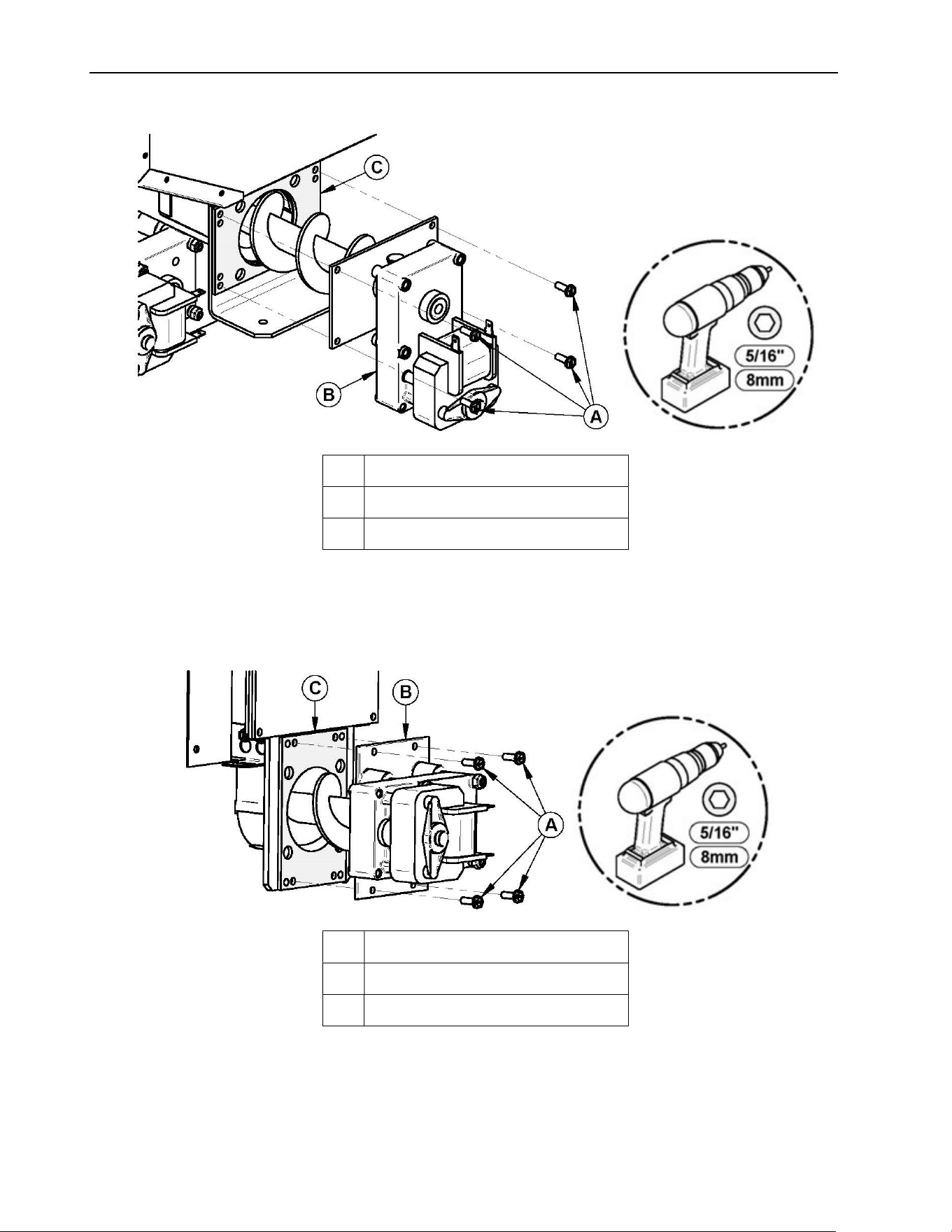
ECO-65R Installation and Operation Manual
59
HOPPER AUGER
A Screws
B Auger and motor assembly
C gasket
BURN POT AUGER
A Screws
B Auger and motor assembly
C GASKET
ECO-65R Installation and Operation Manual
60
8.3.4 L Code
STOVE FEEDS PELLETS, BUT WILL NOT IGNITE AND APPEARS ON THE
CONTROL BOARD
Possible Causes: Possible Remedies:
1. Inadequate fuel is used. Remove the burn pot, make sure that all openings are
clear and check that no ash has filled the tube around
the igniter. Refer to the maintenance section. Also,
make sure that recommended fuel is used (see
Section 4.8.1: Proper Fuel).
2. The igniter is defective. See Section 8.2: Testing a Component and follow
instructions for component check. Test the igniter to
see if it glows. It should take no longer than two
minutes. If it does not glow red, check the wiring and
the F3 fuse. If the wiring is properly connected and
the fuse is good, disconnect the igniter and check its
resistance (ohms, Ω) with a multimeter. If the value is
near zero, replace the igniter.
3. The flue gas temperature probe is
defective.
The probe is a heat sensor located on the exhaust
channel. Its function is to tell the control board that
the stove has ignited properly by measuring the heat
at the exhaust. The pellet stove will not start feeding
pellets at the desired heat setting until it has received
a signal from the temperature probe. If the
temperature probe is faulty, the unit will stop after the
ignition cycle. To display the temperature reading
from the temperature probe press and hold the + and
auger buttons for 3 seconds. Confirm that the value
displayed is equal to the ambient temperature in the
room where the appliance is installed. If this is the
case, turn on the stove and check the same
temperature display. If after 10 minutes, the value
has not increased despite the unit is in operation this
means that the temperature probe is disconnected or
defective. If the temperature rises, the problem may
be with the feed rate or pilot mode. Depending on
many factors (ambient temperature, pellet quality,
etc.) the heat produced by the stove may not be
sufficient to keep the exhaust temperature high
enough. To resolve the situation, increase feed rate
or replace the part (see Section 5.2.2: Adjusting the
Convection Fan Speed).
ECO-65R Installation and Operation Manual
61
8.3.5 d Code
STOVE STOPS FEEDING PELLETS AND APPEARS ON THE CONTROL BOARD
Possible Cause: Possible Remedy:
1. The hopper lid has stayed open for more
than 3 minutes.
As a security measure, the auger stops
turning and feeding pellets as soon as the
hopper lid opens. It will resume normal
operation as soon as the hopper lid is closed.
If the hopper lid stays open for more than 3
minutes, the stove will stop.
2. The hopper lid safety switch is faulty or
disconnected.
Make sure that the switch wiring is properly
connected. If it is, the hopper switch may be
faulty (see Section 8.2: Testing a
Component) and verify the proper function of
the safety switch. Replace it if necessary.
8.3.6 N Code
THE STOVE FUNCTIONS BUT DISPLAYS WARNING CODE
Possible Cause:
Possible Remedy:
1.
A reversed polarity is detected on the
electrical outlet or on the same electrical
circuit.
Test and ensure the proper connections.
2.
No ground is detected or connected in the
wall outlet.
Test and ensure the proper connections of
the electrical wires and/or correct the grounds
of the unit.
8.3.7 C Code
THE STOVE FUNCTIONS BUT DISPLAYS WARNING CODE
Possibles Cause: Possible Remedy :
Warning generated by a power failure
while the stove was running.
The stove will restart on the initial setting once it
cools off.
Note: For a short power failure (less than 5
seconds), the stove will continue to function at the
selected speed.
ECO-65R Installation and Operation Manual
62
8.3.8 I Code
STOVE FEEDS PELLETS, BUT WILL NOT IGNITE AND APPEARS ON THE
CONTROL BOARD
Possible Cause: Possible Remedy:
1. The igniter fuse on the
control board has blown.
Test the resistance (ohms, Ω) with a multimeter. If the
value is near zero, replace the igniter and the F3 fuse.
2. The wiring harness
shorted.
Inspect the wiring and replace any defective wire and or
connector. Make sure the wires are not shorted to the stove
frame. Locate the fuse F3 on the control board and replace
it. See Section 9.2: Testing a Component) and follow
instructions for component check. Test the igniter to see if
it glows. It should take no longer than two minutes.
8.3.9 A Code
STOVE STARTS, BUT DOESN’T FEED PELLETS AND APPEARS ON THE CONTROL
BOARD
Possible Causes: Possible Remedies:
1. The auger
jammed or
auger motor
failed.
See Section 9.2: Testing a Component and test auger motors
independently. If one of the motors is not running check if motor is
defective or if the auger is jammed. Make sure that the hopper lid is
closed. If the auger motor seems defective, check to make sure that
electrical connections are not loose and check the fuses F2 and F6 on
the control board. A defective fuse will be darkened or will have a broken
filament. If the fuses are good, the auger motor may be jammed by an
object.
If the auger is jammed, remove it from its housing (see drawing Section
8.3.3: E Code.) NOTE: IF THE HOPPER AUGER MOTOR FAILED OR
THE HOPPER AUGER IS JAMMED, TO AVOID PELLET SPILLAGE,
EMPTY THE HOPPER OF ITS CONTENTS BEFORE EXECUTING
THE FOLLOWING TESTS. Disconnect the motor and then remove the
four screws on the steel plate that holds the auger shaft to the auger
housing. To have an easier access, remove the rear panel for an easier
access. Pull out the auger from the housing. Once the auger has been
removed, make sure the auger is straight, that the surface is not
damaged and there are no burrs, or broken welds. Remove any foreign
material that may have caused the jam. Inspect the auger housing for
signs of damage such as burrs, rough spots, or grooves cut into the
metal that could have caused a jam. Clean the auger housing thoroughly
to remove all pellet dust.
ECO-65R Installation and Operation Manual
63
2. The wiring
harness
shorted.
Make sure the auger motor wiring is properly connected and not shorted.
8.3.10 Smoke Smell
SMOKE SMELL COMING BACK INTO THE HOME
Possible Causes: Possible Remedies:
1. Venting system leaks. Inspect all vent connections. This is a pressurized venting
system. All vent connector joints must be sealed and
fastened in accordance with the pellet vent manufacturer's
instructions to ensure consistent performance and avoid
smoke and ash spillage (see Section 4.5.1: Installation
Warnings, Cautions and Recommendations Reminder).
2. Worn gaskets Gaskets may be allowing smoke spillage (doors, clean out
traps, etc.). Make sure that all gaskets are in good condition
and replace them with original parts if necessary. Make sure
the door is well adjusted (see Section 7.1.9: Door
Adjustment).
3. Negative pressure. A faint wood-burning odor during ignition or shut down is
normal. Although, if this increases beyond what is
considered normal or if you notice an unusual soot build-up
on walls or furniture, check your venting system carefully for
leaks and make sure all gaskets are in good condition. The
stove exhaust blower produces a negative pressure in the
room. It draws air from the inside of the room, through the
stove and then outdoors. In the same manner, other
appliances can also create a larger negative pressure. In
this case, as the air naturally flows from a high pressure
point to a low-pressure point, a larger negative pressure can
draw smoke from the inside of the stove into the room. The
stove can also be affected by other mechanical ventilation
systems, causing the same effect as mentioned previously.
Using a fresh air intake will prevent negative pressure (see
Appendix D: Combustion Air supply). Also, make sure the
recommended maintenance schedule has been followed.
ECO-65R Installation and Operation Manual
64
8.3.11 Auger Motor Stops Momentarily
AUGER MOTOR STOP FEEDING PELLETS AND COMES BACK ON
Possible Cause: Possible Remedy:
1. The auger motor is overheating and
tripping the internal temperature shutoff
(thermal protector).
It’s possible that the auger is jammed.
Remove it from its housing (see drawing
Section 8.3.3: E Code). NOTE: IF THE
HOPPER AUGER MOTOR FAILED OR THE
HOPPER AUGER IS JAMMED, TO AVOID
PELLET SPILLAGE, EMPTY THE HOPPER
OF ITS CONTENTS BEFORE EXECUTING
THE FOLLOWING TESTS. Disconnect the
motor and then remove the four screws on
the steel plate that holds the auger shaft to
the auger housing. To have an easier access,
remove the rear panel for an easier access.
Pull out the auger from the housing. Once the
auger has been removed, make sure the
auger is straight, that the surface is not
damaged and there are no burrs, or broken
welds. Remove any foreign material that may
have caused the jam. Inspect the auger
housing for signs of damage such as burrs,
rough spots, or grooves cut into the metal that
could have caused a jam. Clean the auger
housing thoroughly to remove all pellet dust.
8.3.12 Poor Burn or Dirty Glass
GLASS “SOOTS” UP AT A VERY FAST RATE
FLAME IS LAZY, DARK, AND HAS BLACK TIPS
AFTER STOVE HAS BEEN ON
FOR A WHILE, THE BURNPOT OVERFILLS
Possible Causes: Possible Remedies:
1. Venting system is dirty.
Refer to Section 7: Maintenance.
2. The flue is not properly
installed.
Make certain the venting system meets the criteria in the
installation section of this manual as well as the venting system
manufacturer’s instructions.
3. Inadequate fuel is
used.
Remove the burn pot, make sure that all openings are clear and
check that no ash has filled the tube around the igniter. Refer to
Section 7: Maintenance. Also, make sure that recommended fuel
is used (see Section 4.8.1: Proper Fuel) and settings are adjusted
to the type of pellets that are being used.
ECO-65R Installation and Operation Manual
65
4. Air intake channel is
restricted.
Visually inspect the air intake channel that leads to the burn pot for
foreign material. Make sure that the air-intake shutter is functional
and free of any obstruction.
5. The
combustion/exhaust
blower failed.
See Section 8.2: Testing a Component and test the combustion
and the exhaust blowers independently. If one of them does not
function, make sure there is power and that the blowers are
properly connected. If they still don’t work, check fuse F4 and F5
on the control board. A blown fuse will be darkened or will have a
broken filament. If the fuses are in good condition, the combustion
or exhaust blower is probably defective. Replace the faulty part.
8.3.13 No Display
The control board does not display any information.
Possible Cause: Possible Remedy:
1. There is no electrical current going to the
stove.
Check if the stove is connected and if there is
current in the wall outlet. Check if the F7 fuse
is blown. Replace it if necessary.
2. TELCO wire is defective or not connected
properly.
Convection blower, combustion blower,
exhaust blower and burn pot auger will start
but the stove will beep continuously. Verify
the connection between the control panel and
the electronic card. Change wire if
necessary.
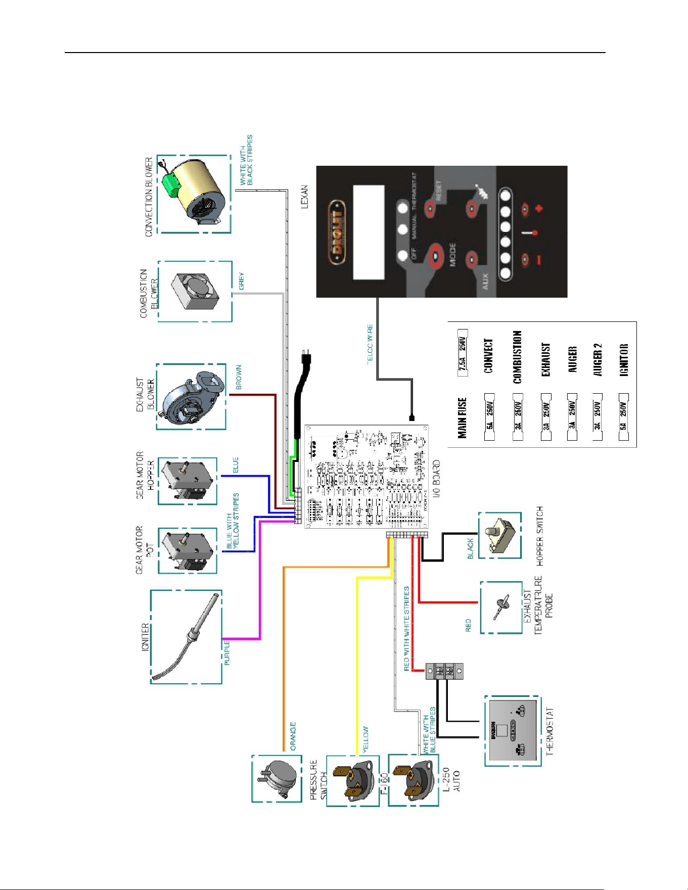
ECO-65R Installation and Operation Manual
66
9 Wiring Diagram
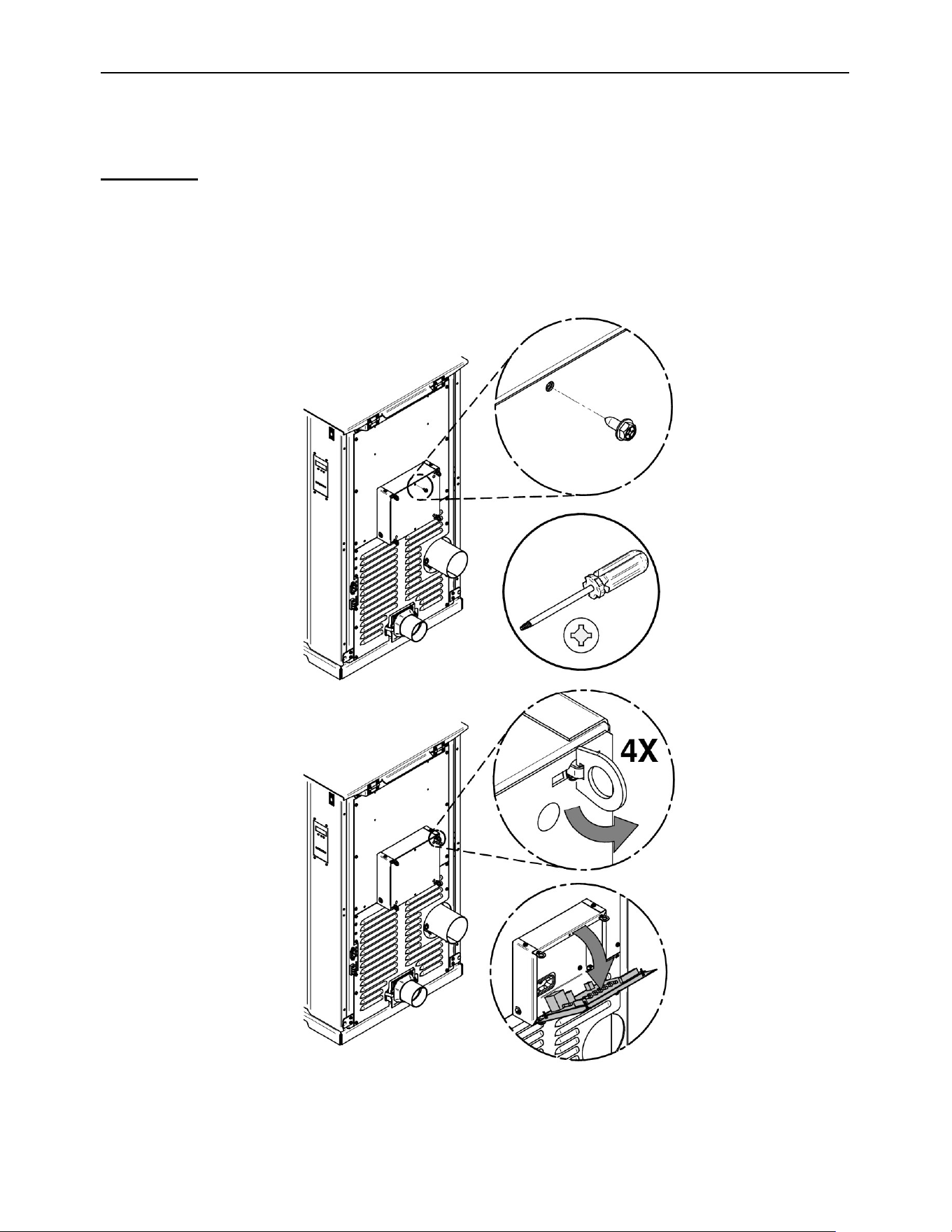
ECO-65R Installation and Operation Manual
67
10 Access to Fuses
WARNING: UNPLUG THE STOVE BEFORE CHANGING THE FUSES.
All fuses are located inside the housing of the electronic board; the housing is on the back
of your stove. Unplug your stove, remove the screw and turn the four spring clips to open
the housing.
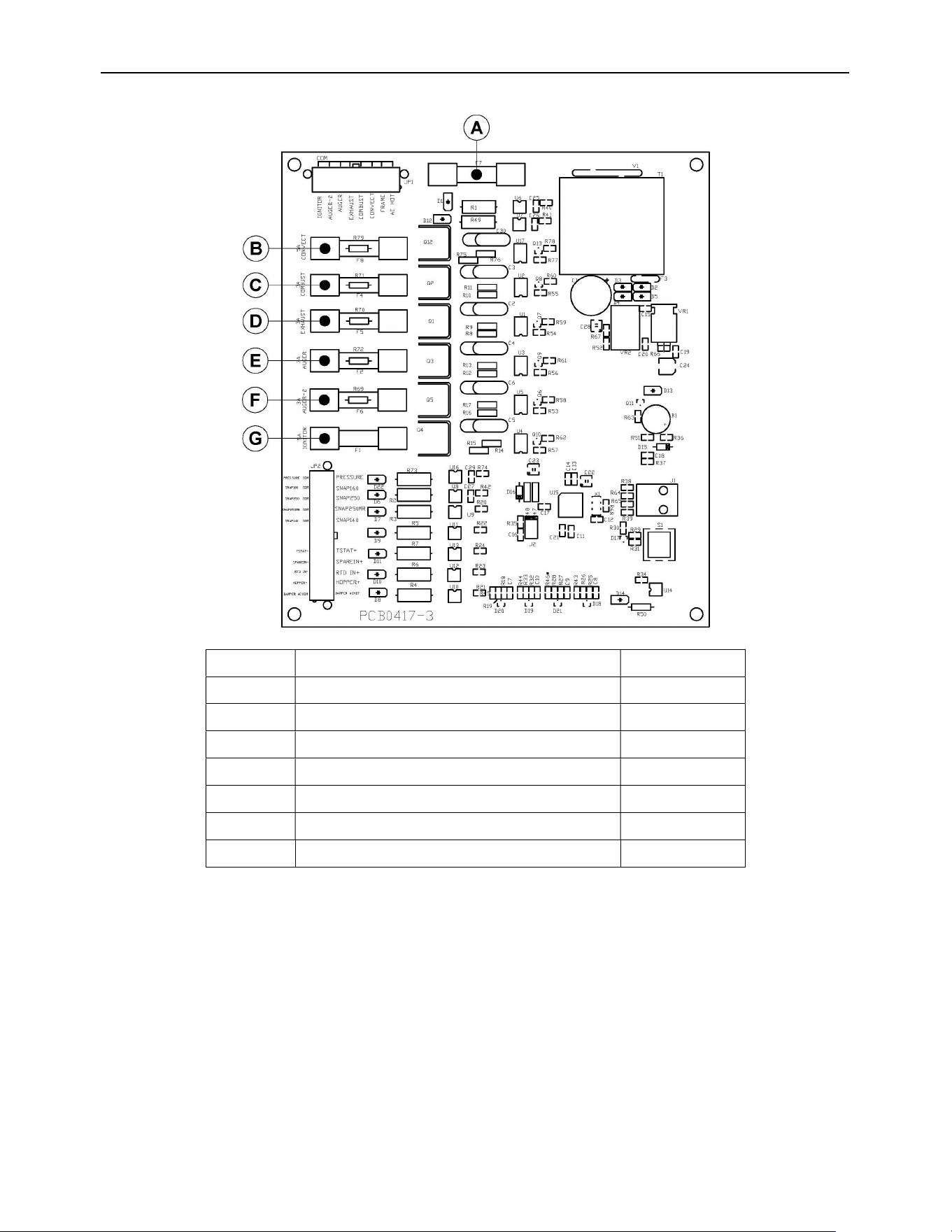
ECO-65R Installation and Operation Manual
68
LETTER
FUSE FUNCTION AMPERAGE
A MAIN BOARD FUSE 7.5A
B CONVECTION BLOWER 5A
C COMBUSTION BLOWER 3A
D EXHAUST BLOWER 3A
E TOP AUGER #1 3A
F BOTTOM AUGER #2 3A
G IGNITOR 5A
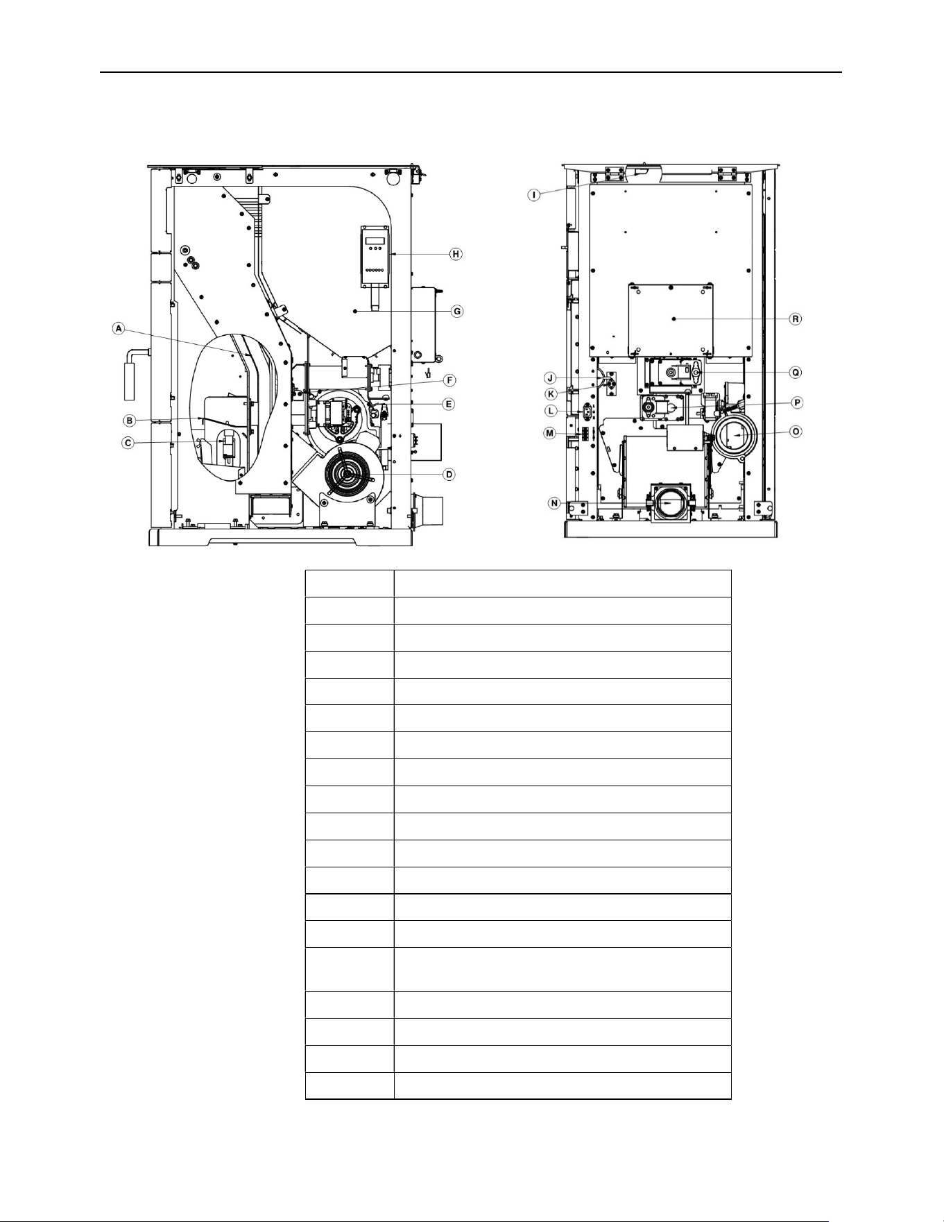
ECO-65R Installation and Operation Manual
69
11 Components Location
LETTER
COMPONENT
A HEAT EXCHANGER TUBES
B BURN POT
C IGNITOR
D CONVECTION BLOWER
E EXHAUST TEMPERATURE PROBE
F L-250 THERMAL SWITCH
G HOPPER
H CONTROL PANEL
I HOPPER SAFETY SWITCH
J PRESSURE SWITCH
K F-160 THERMAL SWITCH
L POWER CORD RECEPTACLE
M THERMOSTAT TERMINAL BLOCK
N
COMBUSTION BLOWER/FRESH AIR
INTAKE
O EXHAUST BLOWER
P BOTTOM AUGER #2
Q TOP AUGER #1
R ELECTRONIC BOARD
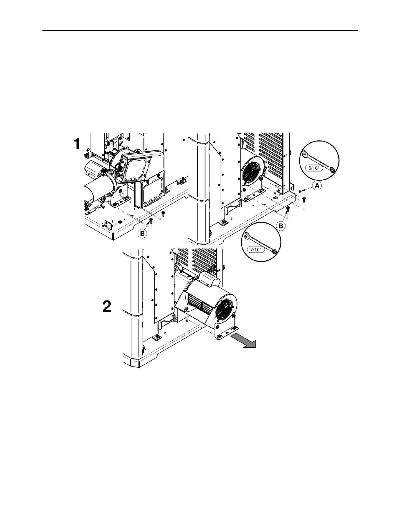
ECO-65R Installation and Operation Manual
70
12 Blower Replacement
CONVECTION BLOWER
Unplug the stove. Remove both side panels to access blower. (1) Unscrew the ground A.
Disconnect the fan from the harness. Unscrew the four-blower anchor bolt B. (2) Slide the
blower from the right side.
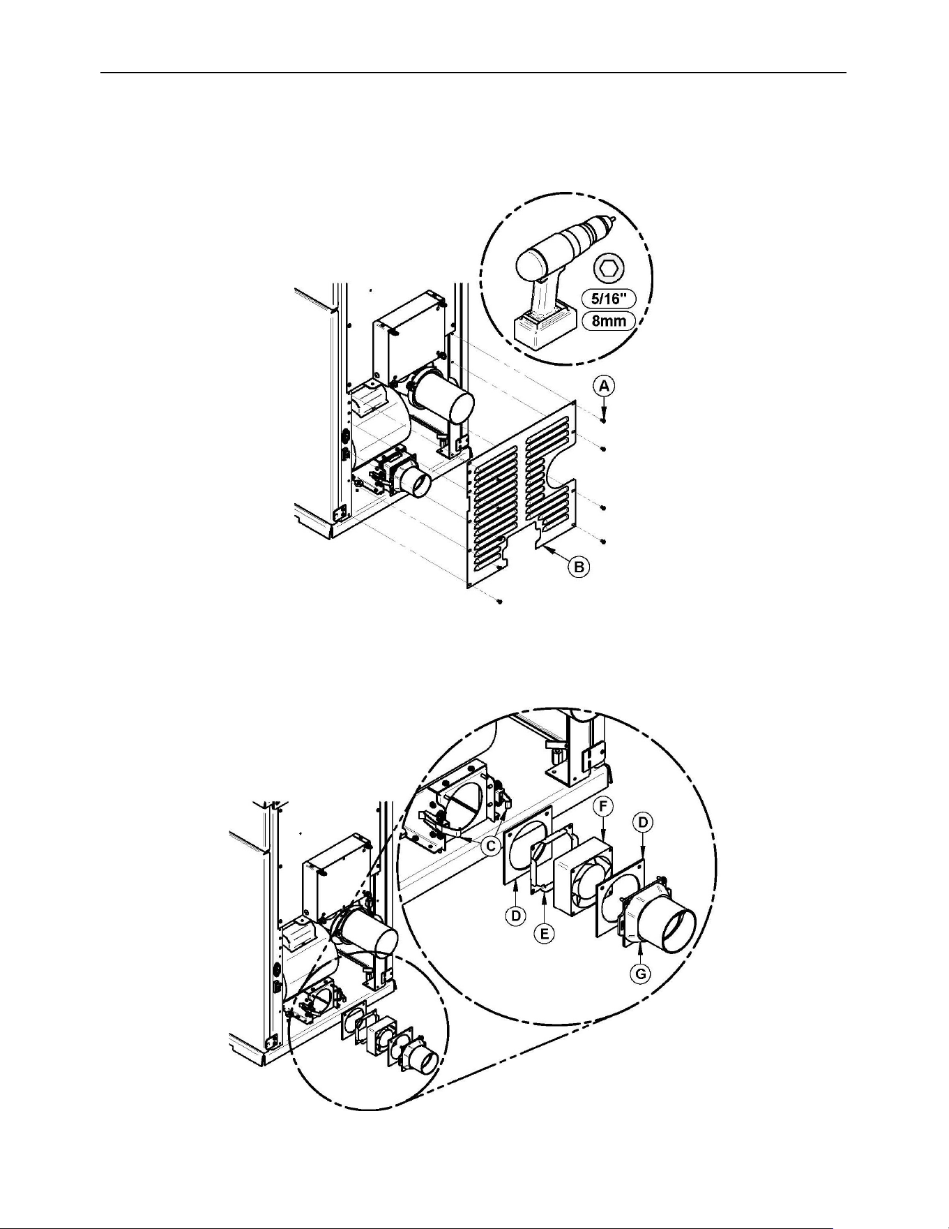
ECO-65R Installation and Operation Manual
71
COMBUSTION BLOWER
Remove the 9 screws (A) and the bottom grille (B).
Unlatch the clamps (C). Remove the back draft shutter (G) and the gasket (D). Pull the
combustion blower (F) and unplug the wire connector from the harness. Remove the plug
(E) of the blower.
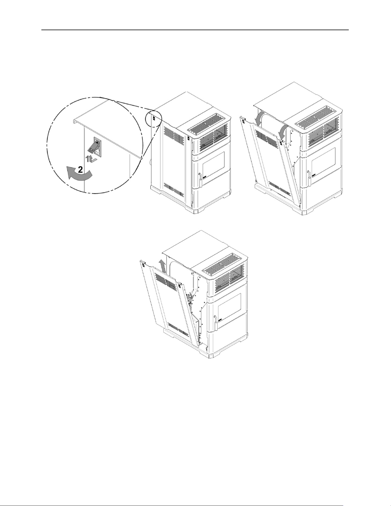
ECO-65R Installation and Operation Manual
72
EXHAUST BLOWER
Remove the left panel.
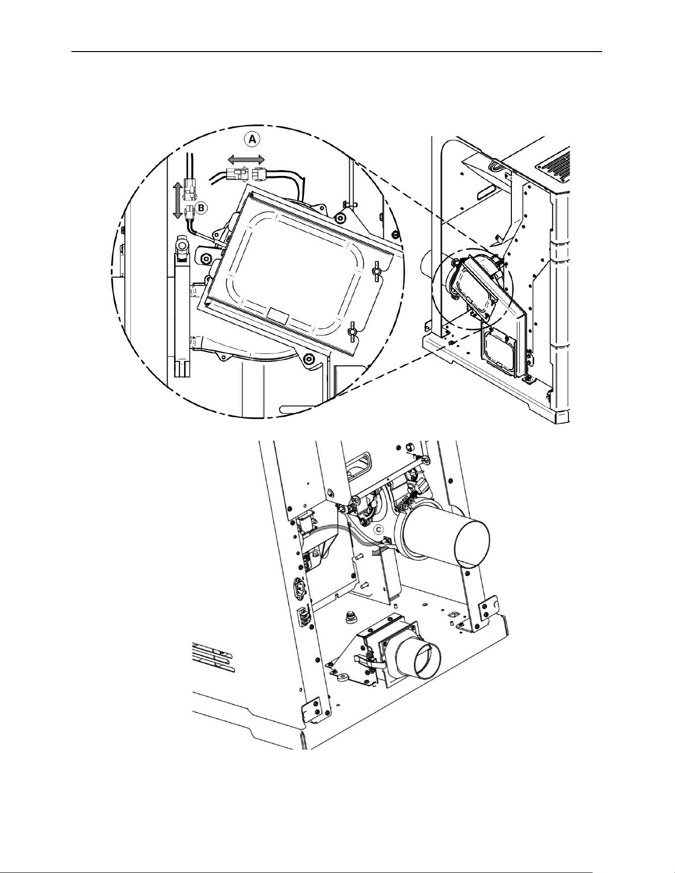
ECO-65R Installation and Operation Manual
73
Disconnect the exhaust motor (A) and exhaust temperature probe (B) connections.
Disconnect the silicone tube from the pressure sensor (C).
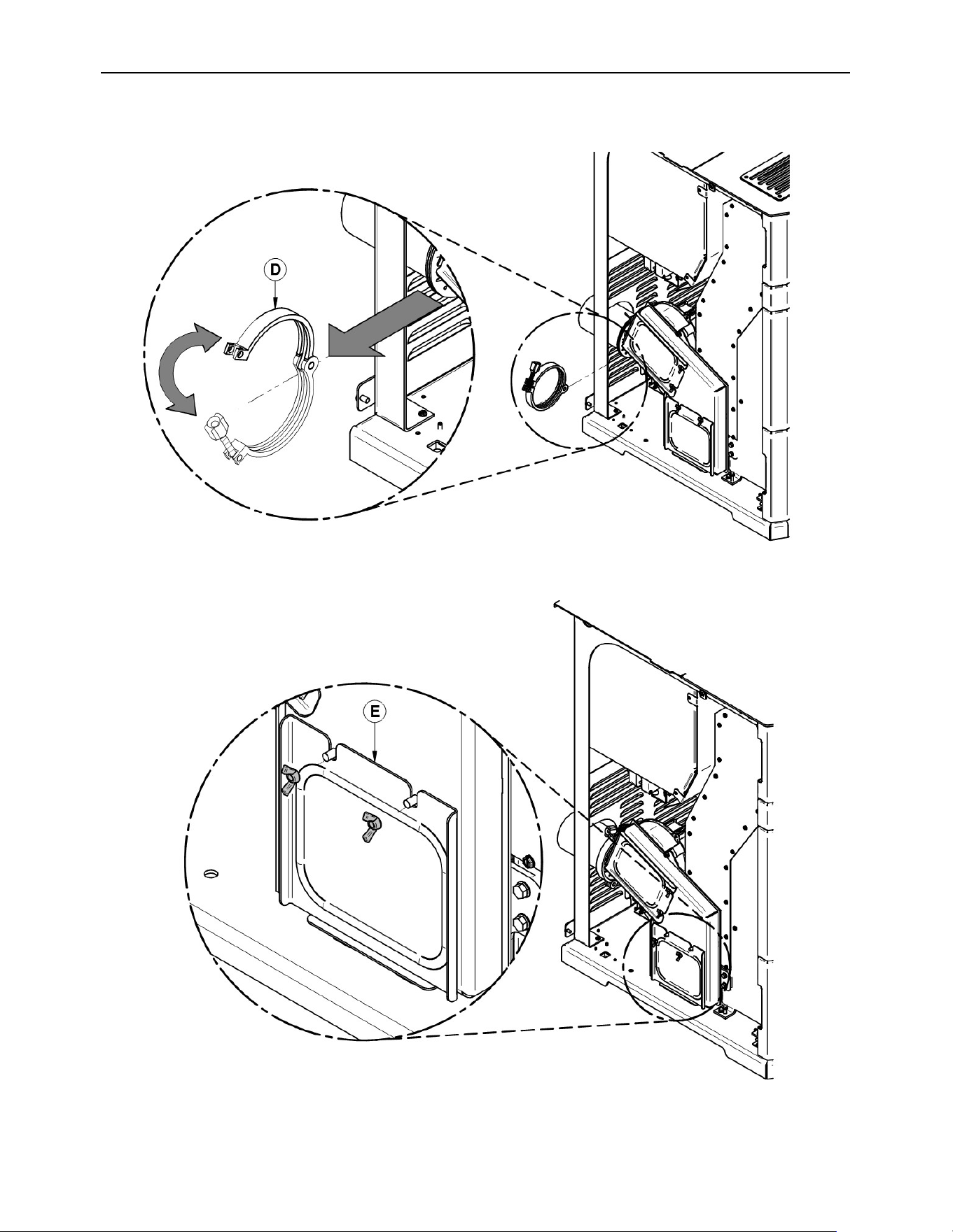
ECO-65R Installation and Operation Manual
74
Remove the clamp (D).
Remove the access panel (E).
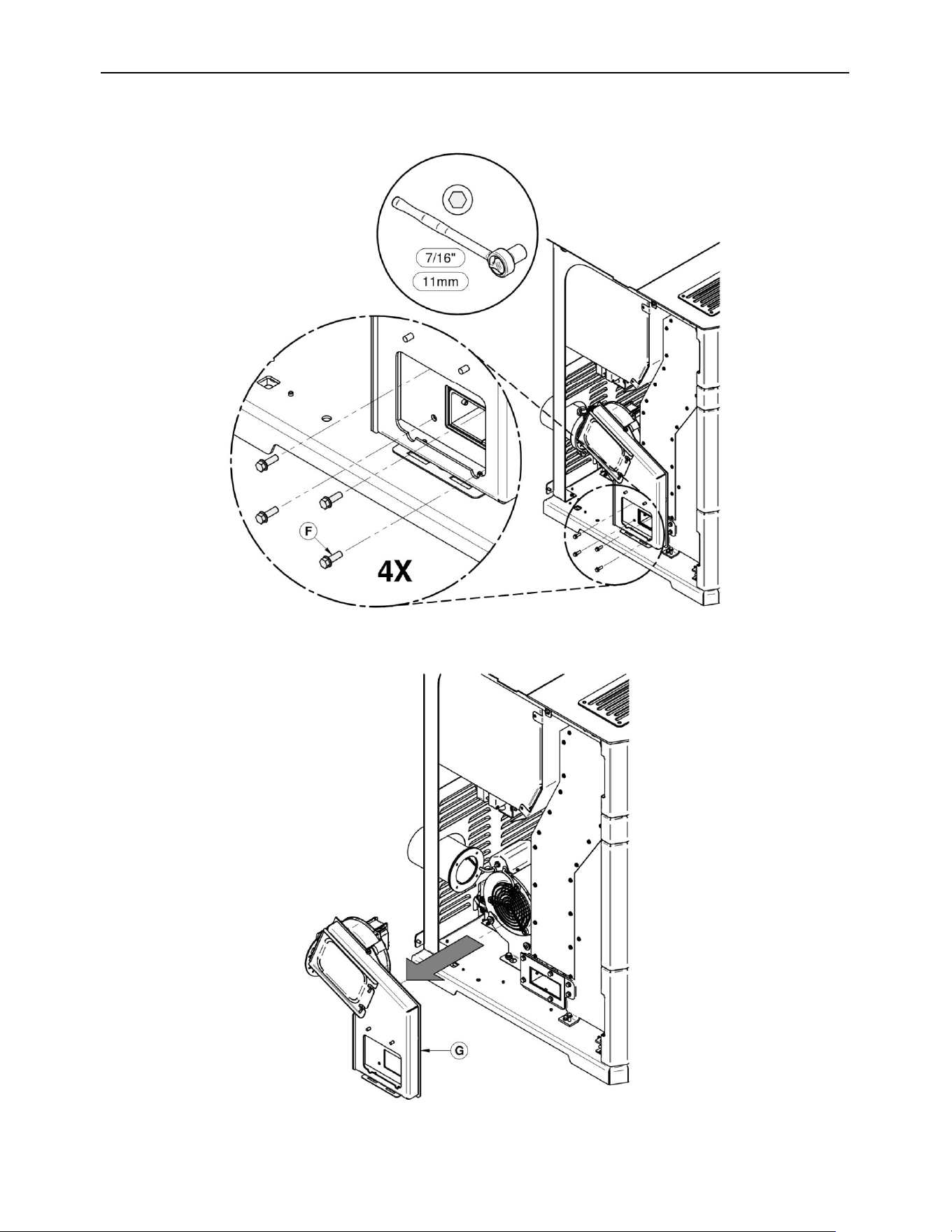
ECO-65R Installation and Operation Manual
75
Remove the screw (F) located in the opening of the trapdoor.
Remove the duct assembly (G).
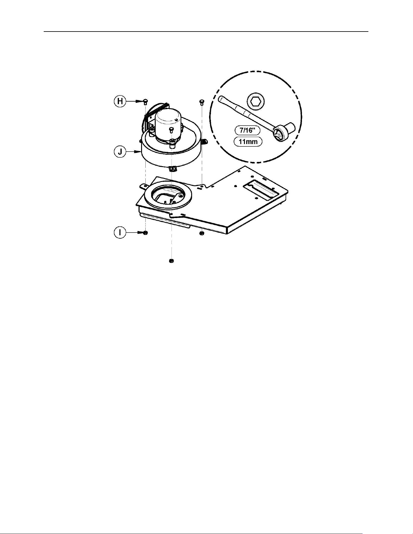
ECO-65R Installation and Operation Manual
76
Remove the bolts (H) and nuts (I) to remove the exhaust blower (J)
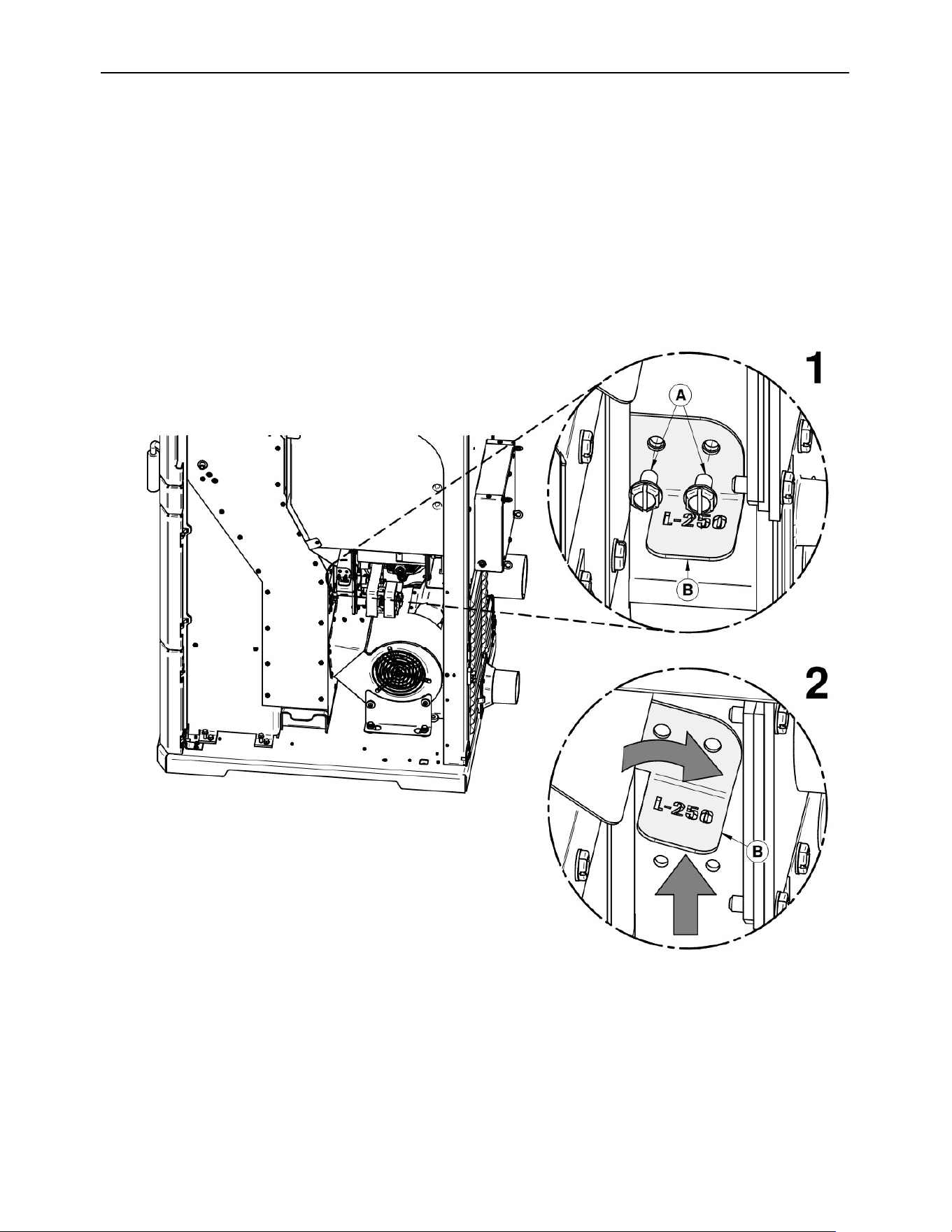
ECO-65R Installation and Operation Manual
77
13 L-250 and F-160 Thermal Switch Replacement
L-250
1. Remove both retaining screws (A) holding the thermal switch support bracket (B).
2. Lift up the support bracket. Rotate the bracket 90° clockwise then pull the bracket toward
you.
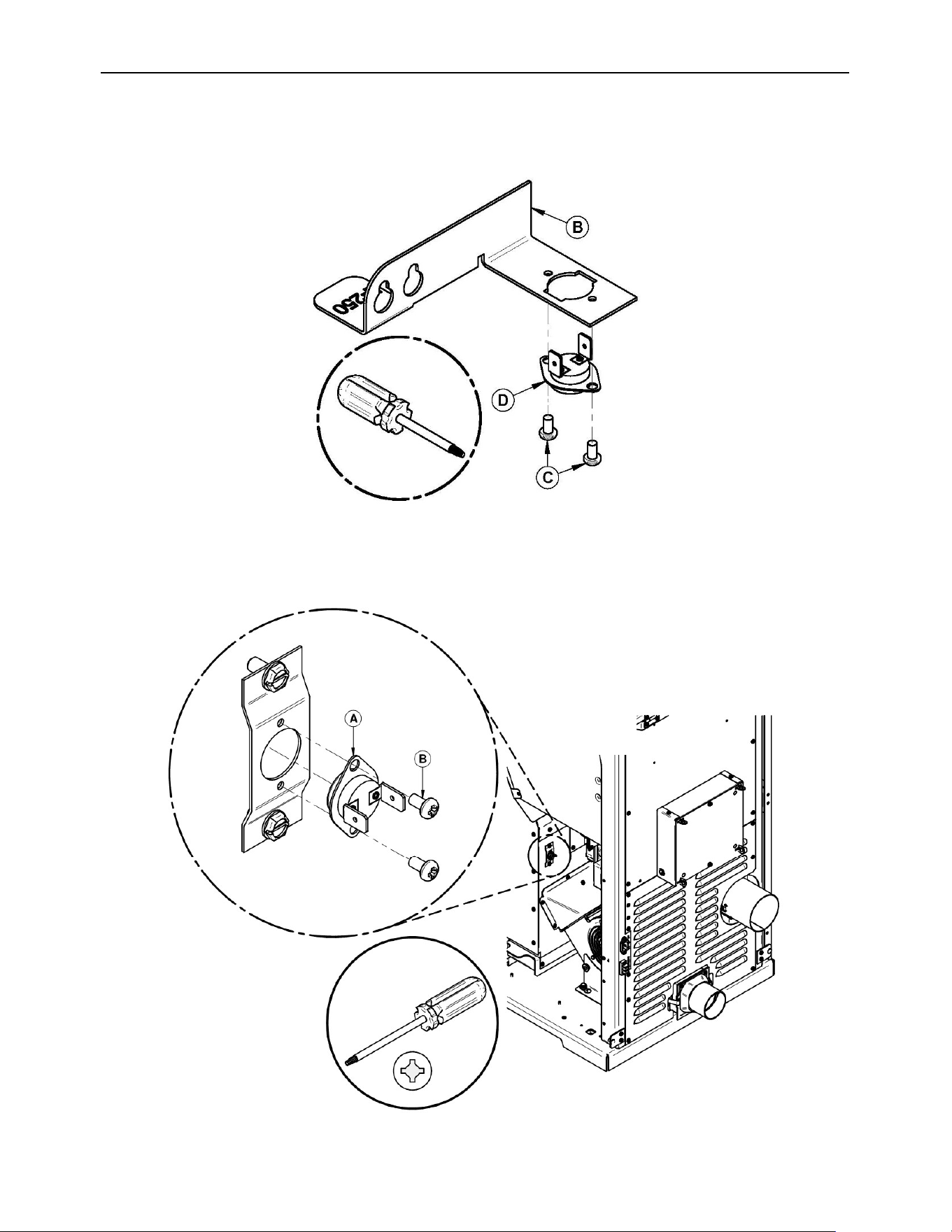
ECO-65R Installation and Operation Manual
78
Remove the faulty thermal switch. Replace new thermal switch (D) underneath the bracket
(B) by means of 2 screws (C).
F-160
Unscrew both screws (B) and take out the thermal switch F-160 (A).
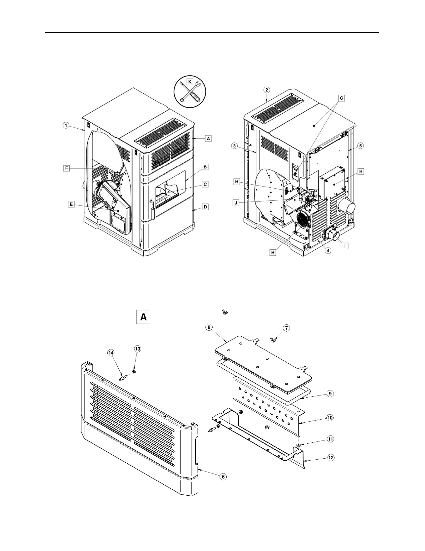
ECO-65R Installation and Operation Manual
79
14 Exploded View and Replacement Parts
SECTION A
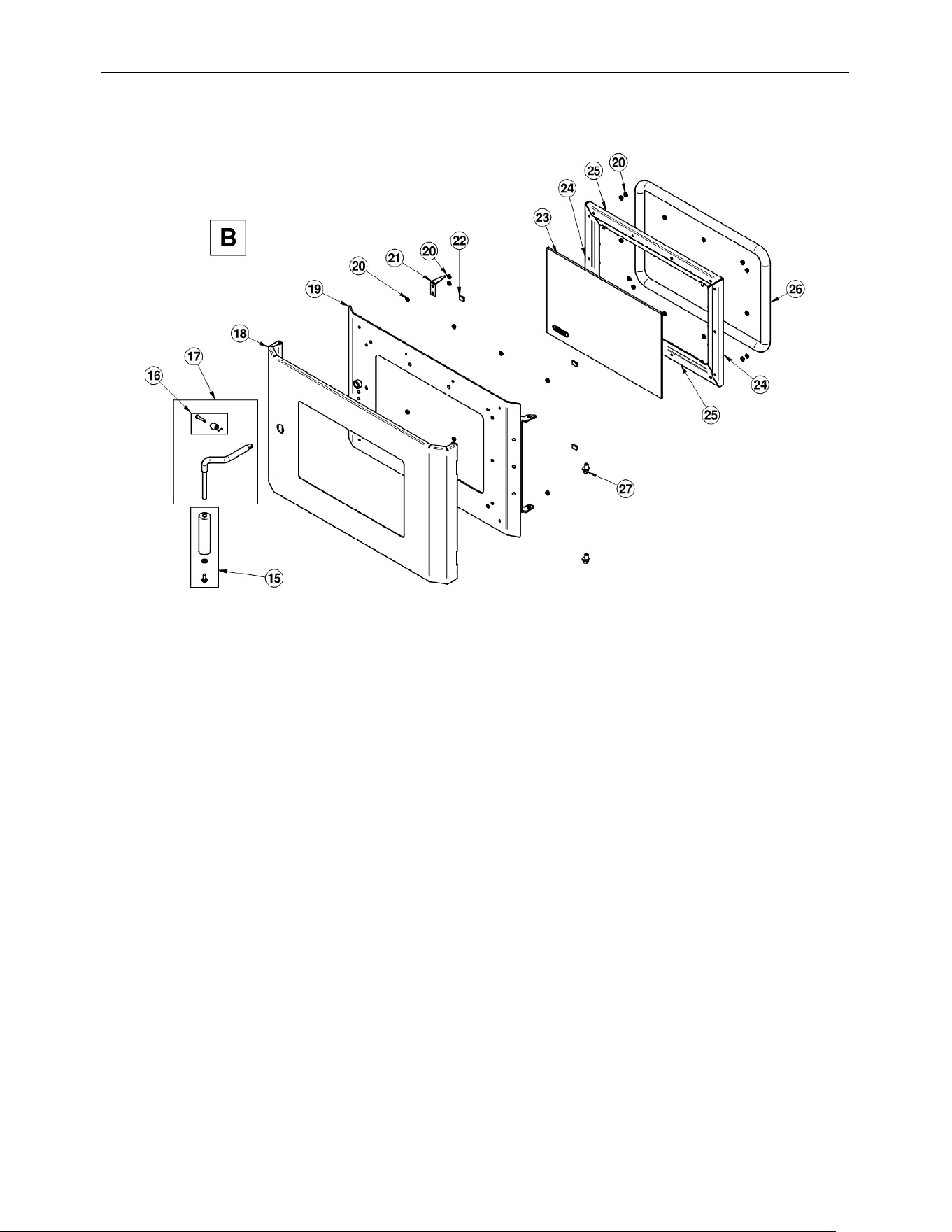
ECO-65R Installation and Operation Manual
80
SECTION B
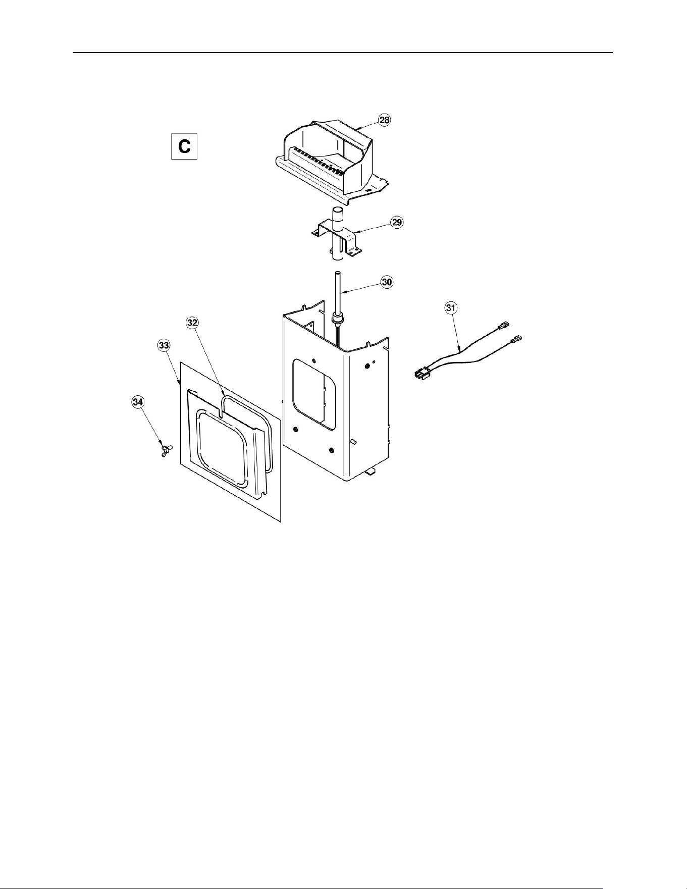
ECO-65R Installation and Operation Manual
81
SECTION C
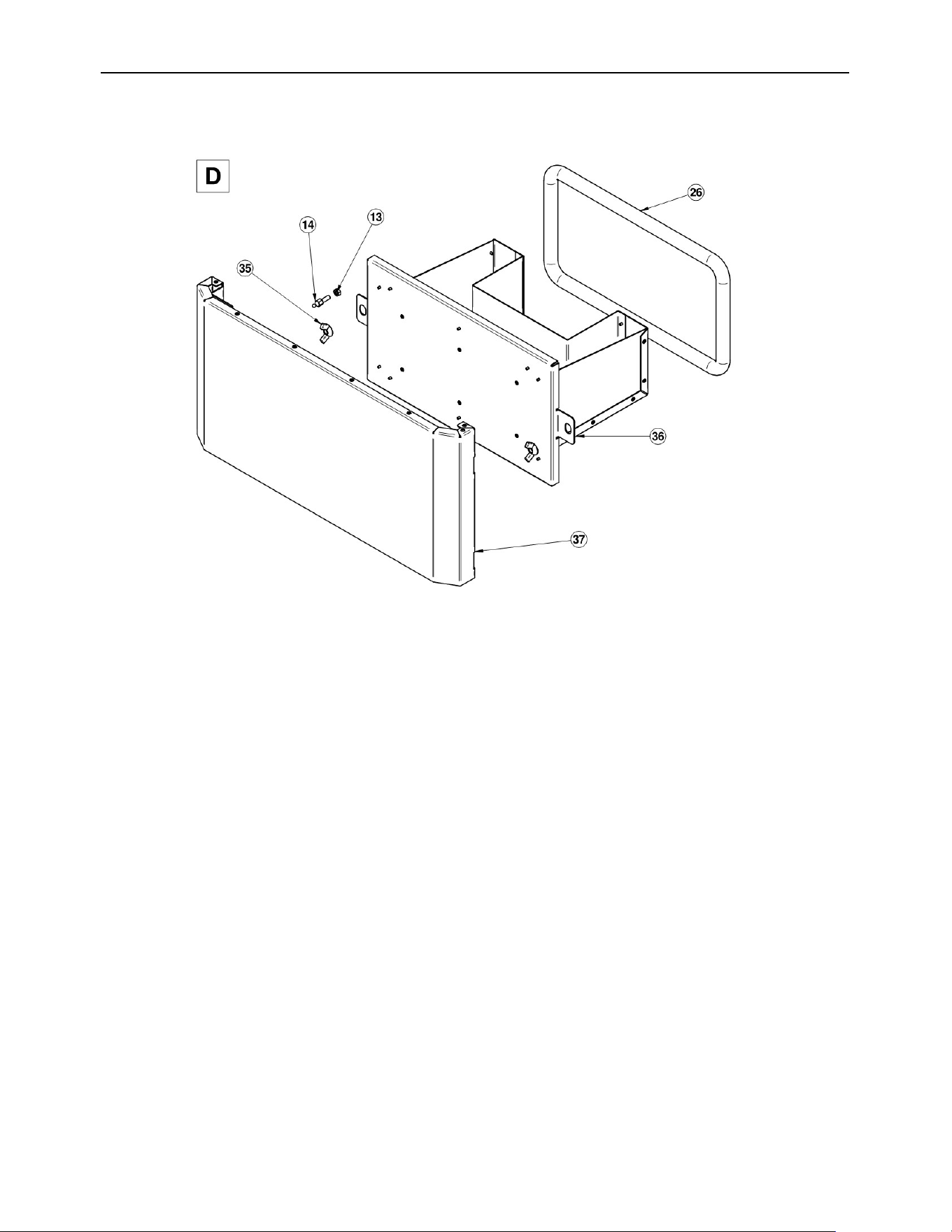
ECO-65R Installation and Operation Manual
82
SECTION D
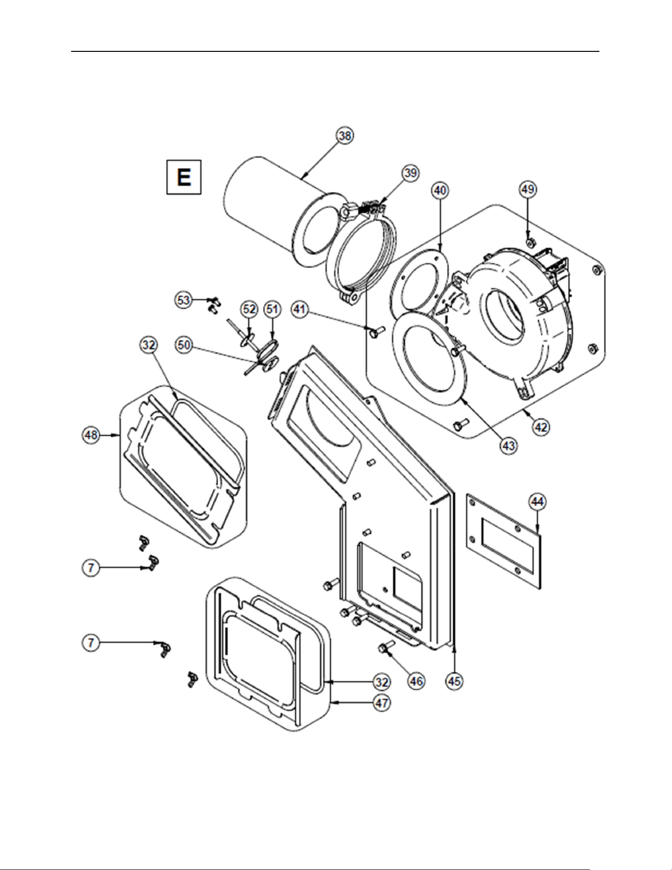
ECO-65R Installation and Operation Manual
83
SECTION E
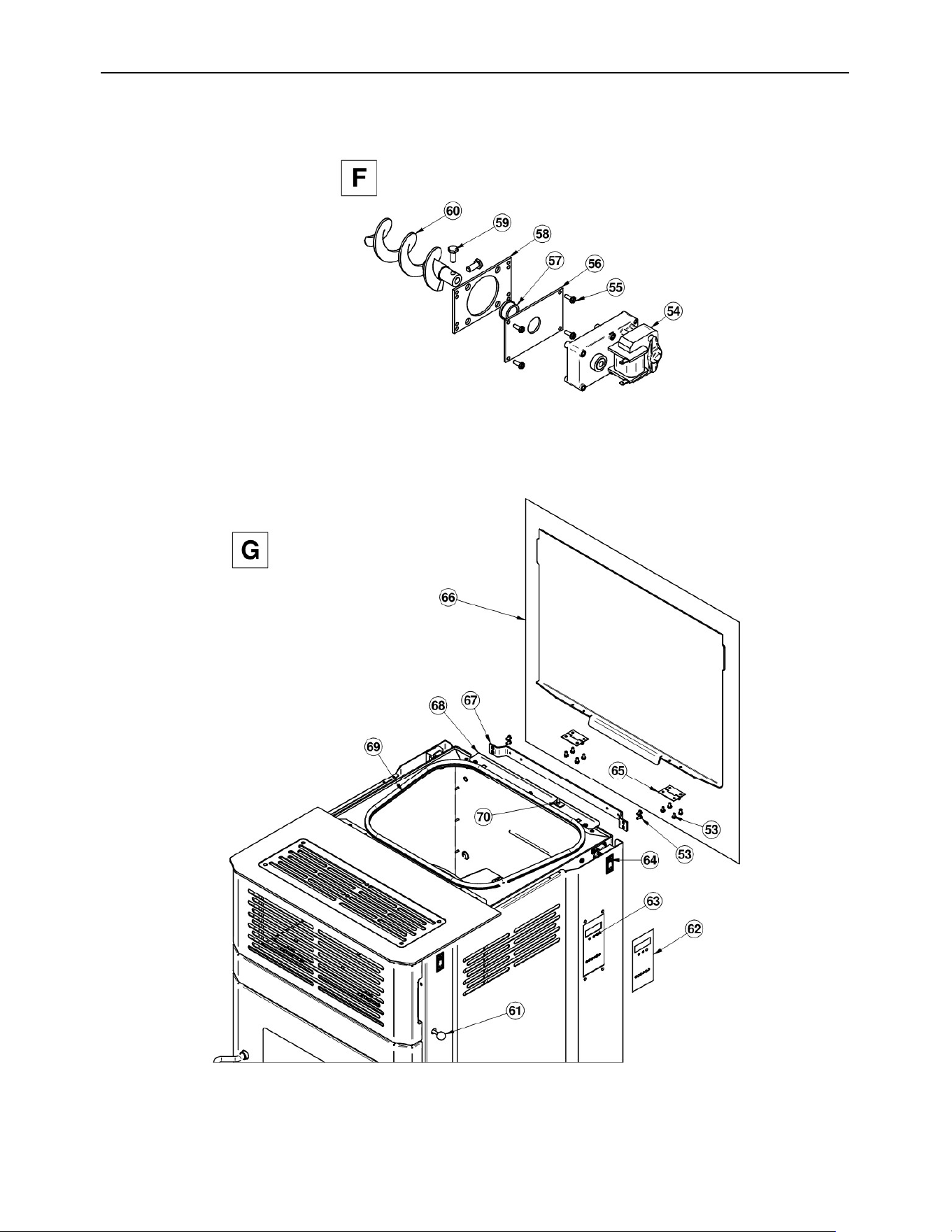
ECO-65R Installation and Operation Manual
84
SECTION F
SECTION G
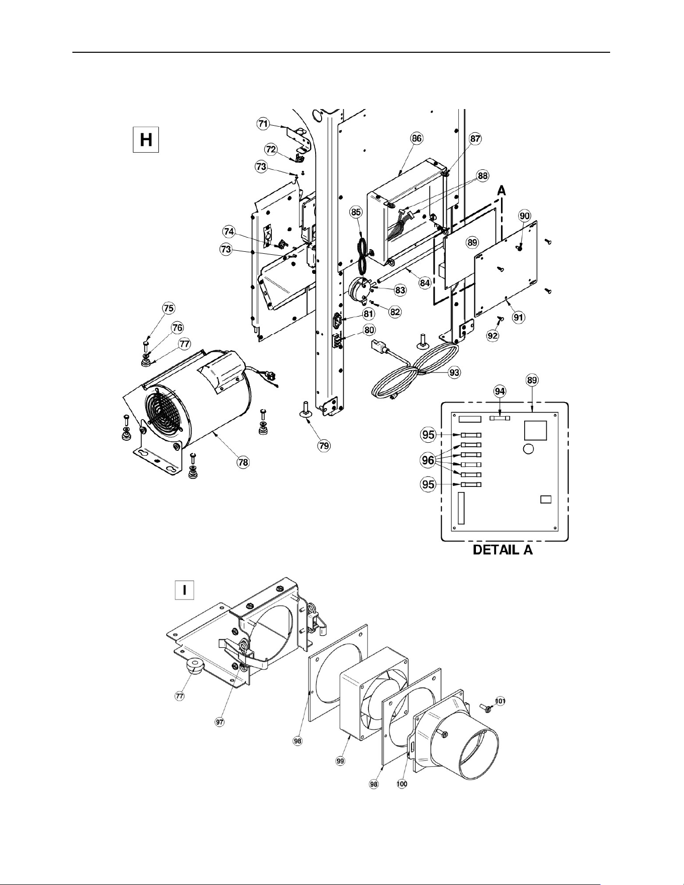
ECO-65R Installation and Operation Manual
85
SECTION H AND I
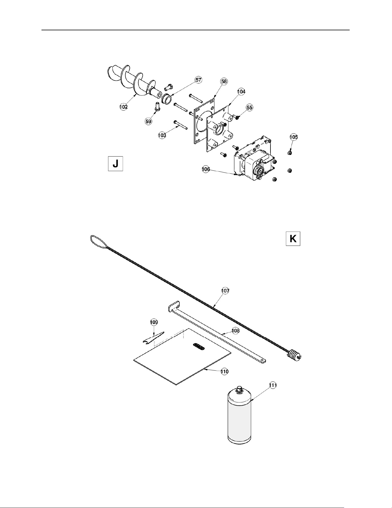
ECO-65R Installation and Operation Manual
86
SECTION J
SECTION K
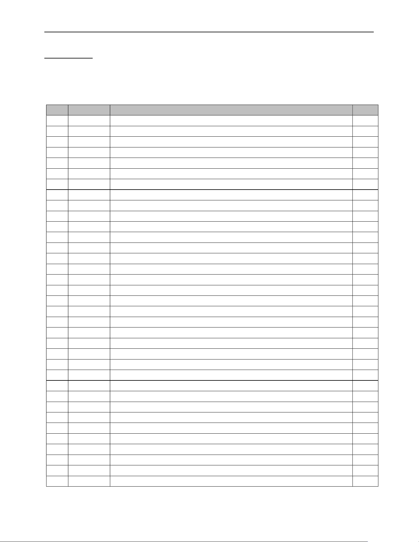
ECO-65R Installation and Operation Manual
87
IMPORTANT: THIS IS DATED INFORMATION. When requesting service or replacement
parts for your stove, please provide the model number and the serial number. We reserve
the right to change parts due to technology upgrade or availability. Contact an authorized
dealer to obtain any of these parts. Never use substitute materials. Use of non-approved
parts can result in poor performance and safety hazards and will void your warranty.
# Item Description Qty
1 SE67209 LEFT PANEL ASSEMBLY 1
2 SE75600 TOP ASSEMBLY 1
3 PL75639 LEFT PANEL 1
4 PL75624 BACK PLATE LOUVER 1
5 PL67078 REAR TOP PANEL 1
6 SE67210 DECORATIVE GRID ASSEMBLY 1
7 30484 WING NUT 1/4-20 X 1/2'' 6
8 SE67219 MAINTENANCE ACCESS PANEL 1
9 AC06900 BLACK ROUND GASKET 1/2'' X 9' WITH ADHESIVE KIT 1
10 PL67219 BAFFLE 1
11 30220 FLANGED LOCKNUT 1/4-20 4
12 PL67220 BLOCKING PLATE 1
13 31133 NUT M6 STAINLESS STEEL 3
14 31050 SPHERICAL NAIL 3
15 SE70731 WOOD HANDLE KIT 1
16 AC09185 DOOR LATCH KIT 1
17 SE70730 DOOR HANDLE ROD KIT 1
18 PL67224 DOOR OVERLAY 1
19 SE67212 DOOR ASSEMBLY 1
20 30417 BLACK HEX NUT #8-32 24
21 PL75636 HANDLE STOPPER 1
22 AC06810 1/8" X 3/8" X 6' SELF ADHESIVE BLACK GASKET 1
23 PL67237 GLASS WITHOUT GASKET 14-11/16'' X 9-3/8'' 1
24 PL75637 LOWER GLASS AND GASKET RETAINER 2
25 PL75647 LOWER GLASS AND GASKET RETAINER 2
26 AC06730 SILICONE AND 1'' X 8' BLACK DOOR GASKET KIT 1
27 31226 HINGE PIN 2
28 SE67216 COMBUSTION POT 1
29 44146 IGNITER TUBE 1
30 SE44132 IGNITER ASSEMBLY 120V-300W 1
31 60360 IGNITOR WIRE EXTENSION WITH QUICK CONNECT (23.375'') 1
32 AC06815 3/16'' X 5' BLACK GASKET AND SILICONE KIT 1
33 SE67033 BURN POT RECEPTACLE CLEAN-OUT ACCESS DOOR 1
34 30485 WING NUT 1/4-20 X 1/2'' ZINC PLATTED 1
35 30416 WING NUT 3/8"-16 2
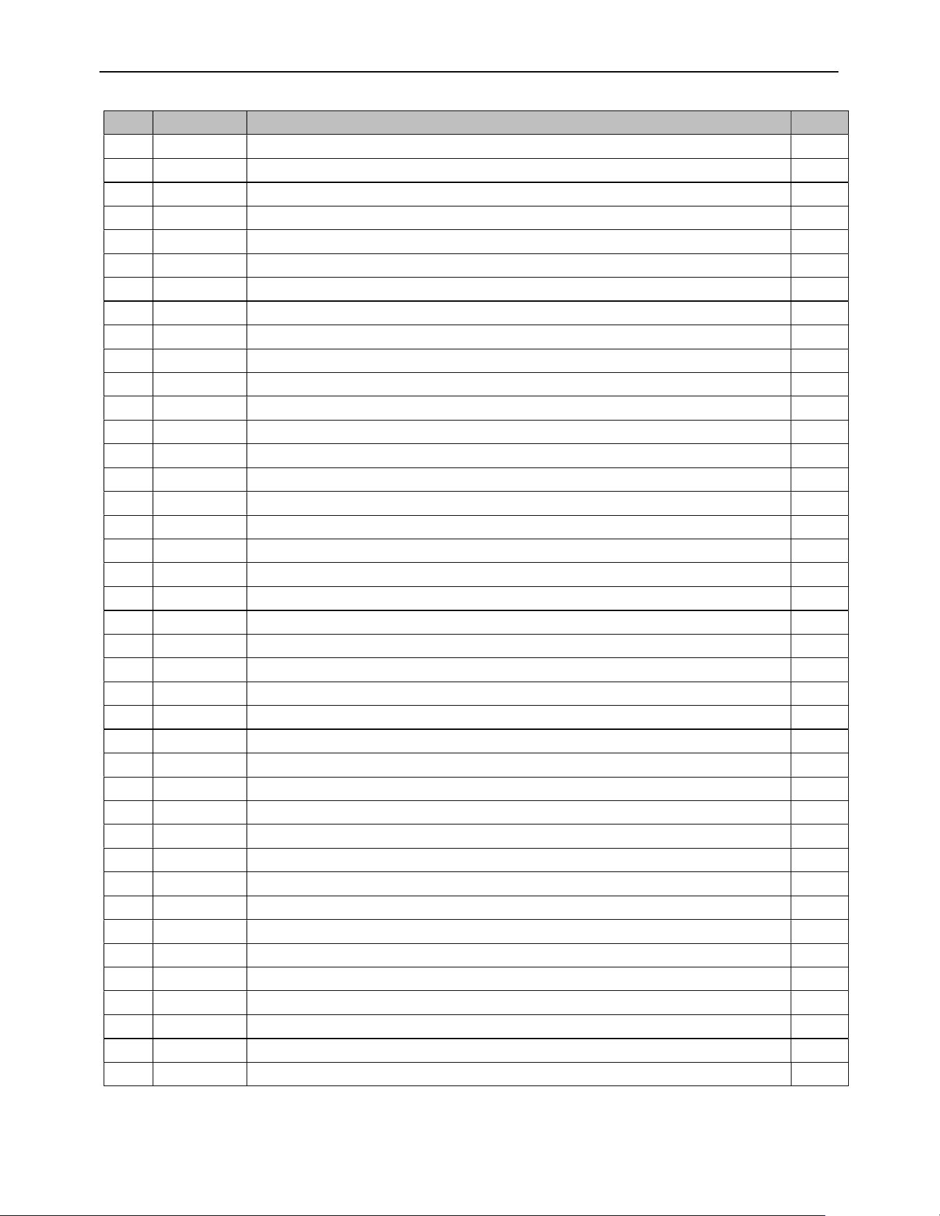
ECO-65R Installation and Operation Manual
88
# Item Description Qty
36 SE67242 ASH PAN 1
37 SE67225 ASH PAN ASSEMBLY 1
38 SE67018 EXHAUST ADAPTER PIPE 1
39 30762 VENT ADAPTER SECURE CLAMP 1
40 21392 EXHAUST ADAPTER GASKET 1
41 30093 BOLT 1/4-20 X 3/4" HEX GRADE 5 3
42 SE44193 EXHAUST FAN 1
43 21393 EXHAUST BLOWER GASKET 1
44 21401 EXHAUST CHANEL GASKET 1
45 SE75607 EXHAUST CHANEL 1
46 30094 HEX SCREW WASHER HEAD 1/4-20 X 3/4" F ZINC TYPE 42
47 SE75611 CLEANING PANEL 1
48 SE75609 CLEANING PANEL 1
49 30220 FLANGED LOCKNUT 1/4-20 4
50 21418 RTD GASKET 1
51 44052 BLACK TY-RAP 8" 3
52 44183 EXHAUST RTD PROBE 1
53 30029 THREAD CUTTING SCREW 10-24 TYPE "F" X 3/8" HEX WASHER 20
54 44038 AUGER GEAR MOTOR 1 RPM 1
55 30026 THREAD CUTTING SCREW 10-24 F 5/8" HEX WASHER HEAD 11
56 PL62281 AUGER BUSHING PLATE 1
57 30528 BRASS BUSHING FOR PELLET STOVE AUGER 2
58 21193 AUGER SUPPORT GASKET 2
59 30092 BOLT 5/16''-18 X 3/4" HEX GRADE 5 2
60 24030 AUGER 1
61 30562 3/4" X 1/4''-20 ROUND HANDLE FOR EXCHANGER ROD 1
62 SE44139 MEMBRANE SWITCH ON COVER 1
63 SE75668 LEXAN BOARD BOX 1
64 30572 RETRACTABLE LATCH HANDLE (BLACK) 4
65 30013 HINGE 2" X 1 1/2" 2
66 SE67095 UPPER LID 1
67 PL67141 HOPPER STOPPER 1
68 PL67155 SWITCH SUPPORT 1
69 AC06820 EPDM GASKET KIT 3/8 X 3/8 X 37/64 (5') 1
70 44098 HOPPER LID SAFETY SWITCH 1
71 PL67149 L250-25 AUTOMATIC SUPPORT 1
72 44059 THERMODISC 36T11 L250-25 AUTOMATIC 1
73 30080 METAL SCREW #6 X 1/4 TYPE B PAN PHILLIPS 2
74 44058 THERMODISC 36T12 F160 1
75 31402 HEX HEAD SCREW 1/4-20 X 1-3/4" PARTIALLY THREADED 4
ECO-65R Installation and Operation Manual
89
# Item Description Qty
76 31180 WASHER (ID .322, OD .562, THINK .175) 4
77 30335 BLOWER ANTIVIBRATION CUSHION 5
78 SE75656 CONVECTION FAN 1
79 30050 LEVELING BOLT 3/8-16 X 1 1/2" 2
80 60036 THERMOSTAT TERMINAL 1
81 60196 POWER CORD RECEPTACLE 1
82 30138 METAL SCREW #6 3/8'' QUADREX ''A'' TYPE BLACK 2
83 44029 PRESSURE SWITCH 1
84 49006 3/8" X 24" SILICONE HOSE (INT.1/16"Ø 0.156'' +/- 0.010'') 1
85 60327 JUNCTION WIRE MAIN CONTROL BOARD TO LCD 1
86 SE64494 MOTHER BOARD HOUSING 1
87 30710 SPRING CLIP 4
88 60342 MAIN CONTROL BOARD WIRE HARNESS 1
89 PL68623 PROGRAMMED I/O PC CONTROL BOARD 1
90 31048 SCREW #10 X 1/2 HWH PH TYPE AB ZINC PLATED/BLACK PAINTED HEAD 3
91 PL64459 MOTHER BOARD HOUSING COVER 1
92 30408 ELECTRONIC BOARD CLIP 4
93 60331 POWER CORD 6' 1
94 44013 FUSE 7.5A / 250V / 1/4"Ø X 1 1/4''L 1
95 44015 FUSE 5A / 250V / 1/4"Ø X 1 1/4''L 2
96 44016 FUSE 3A / 250V / 1/4"Ø X 1 1/4''L 3
97 30439 SPRING CLAMP ZINC PLATED BRIGHT CHROMATE DIP 2
98 21400 COMBUSTION FAN GASKET 2
99 44195 AXIAL BLOWER 115V 9W 92 X 92 X 38 (PLASTIC IMPELLER) 1
100 30777 PLASTIC BACKDRAFT DAMPER ASSEMBLY 1
101 30502 SELF TAPING SCREW #8 - 32 X 1/2'’ TYPE F x 3/4 HEX FLAT HEAD 2
102 24031 AUGER 1
103 30232 MECHANICAL SCREW 10-32 x 1-3/4'' PAN QUADREX ZINC 4
104 24233 GEAR MOTOR BRACKET 1
105 30233 NYLON HEX LOCK NUT 10-32 ZINC 4
106 44307 GEAR MOTOR FOR PELLET STOVE 2.4 RPM (Orange Dot Label) 1
107 30798 HEAT EXCHANGER MAINTENANCE BRUSH Ø1 1/8'' - 42'' 1
108 PL67171 SCRAPER 1
109
PL74535 WRENCH FOR ECCENTRIC HINGE 1
110
SE46384 ECO-65R INSTRUCTION MANUAL KIT 1
111
AC05963 METALLIC BLACK STOVE PAINT - 85 g (3oz) AEROSOL 1
ECO-65R Installation and Operation Manual
90
APPENDIX A: HORIZONTAL AND VERTICAL VENT CHART
Possible Vertical vent length (feet)
Possible Horizontal vent length (feet)
For example, let’s imagine an installation consisting of a horizontal
vent coming out at the back of the stove on a total distance of 8
feet. This horizontal run is followed by a tee and a 6-foot vertical
rise. This type of installation is not acceptable. As you can see,
the vent termination is clearly outside the allowed configuration
zone on the chart because the venting system proposed does not
have at least one foot of vertical rise for each foot of
horizontal run.
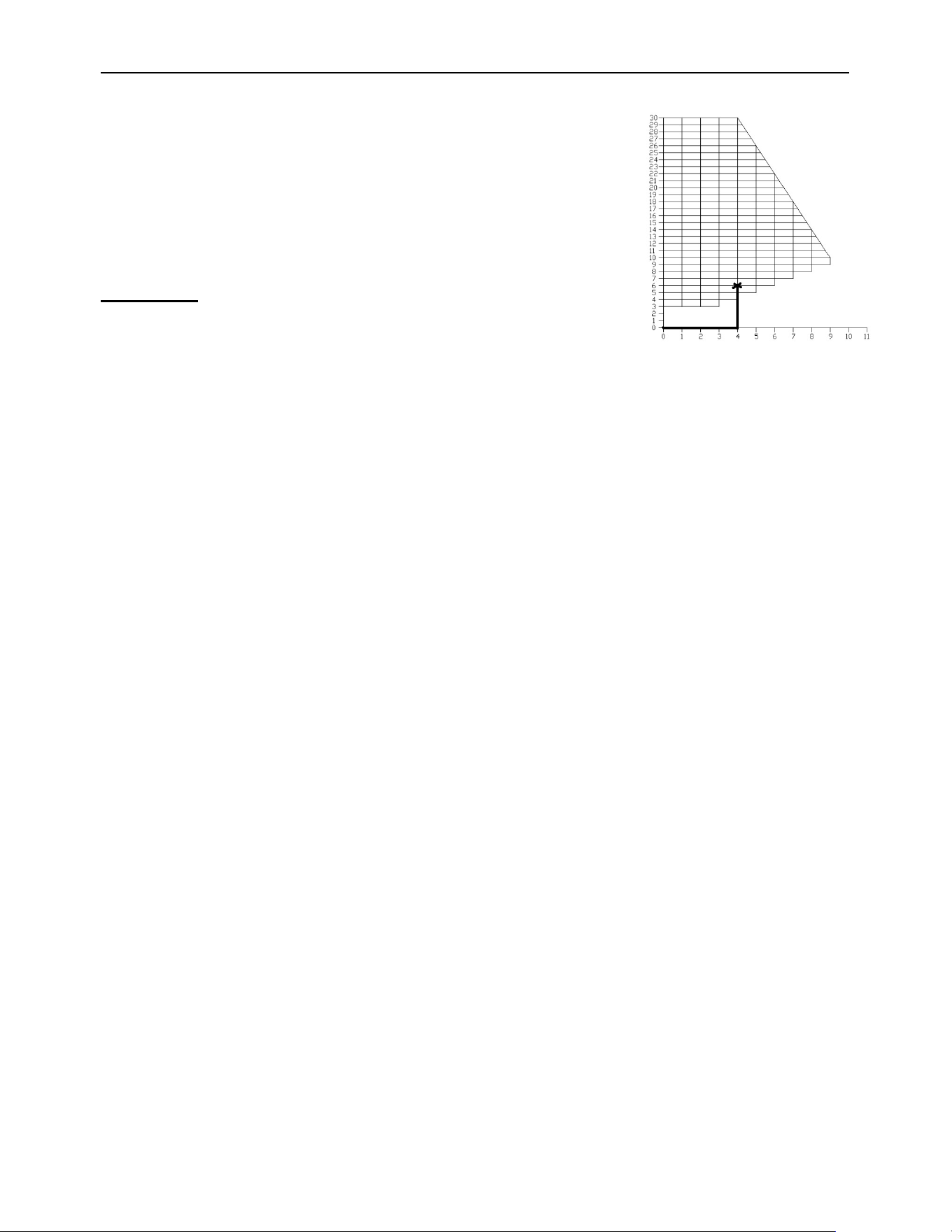
ECO-65R Installation and Operation Manual
91
Instead, if the installation consisted of a horizontal vent coming
out at the back of the stove on a total distance of 4 feet, followed
by a tee and a 6-foot vertical rise, it would be acceptable. The
termination is within the allowable configuration zone on the chart
since it would have at least one foot of vertical rise for each foot
of horizontal run. Furthermore, the total vertical rise is at least 3-
feet high.
WARNING: To reduce the risk of smoke spillage there
should always be at least one foot of vertical rise for each
foot of horizontal run. In all cases, at least 3 feet of vertical
rise is needed.
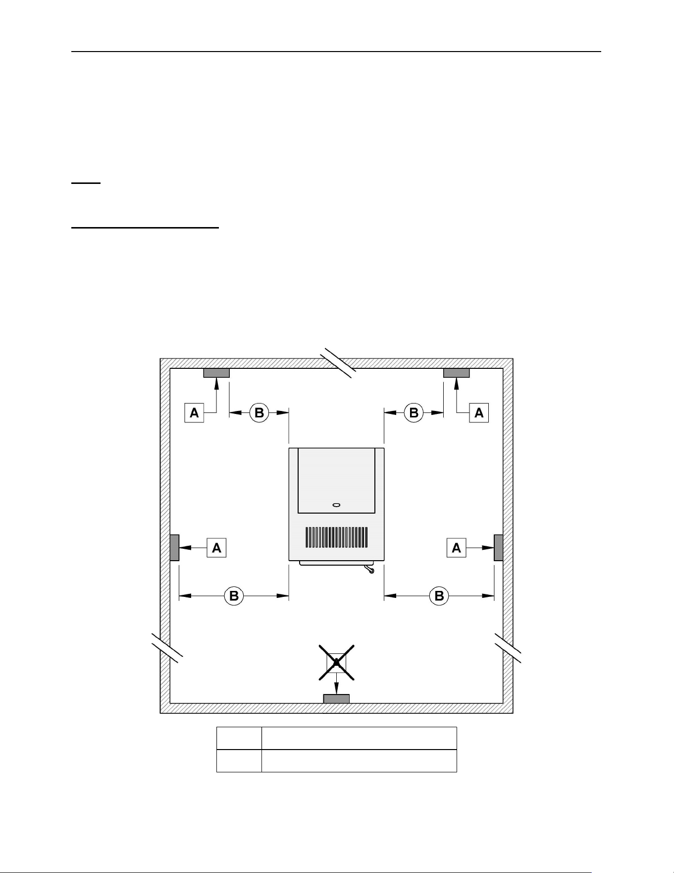
ECO-65R Installation and Operation Manual
92
APPENDIX B: INSTALLING A THERMOSTAT (AC05558)
Using a thermostat will help you maintain a constant temperature throughout the house. A
low voltage thermostat (24 volts) is required. A fixed wall mount or handheld model can be
used.
Note: Thermostat manufacturer’s instructions always override the information
published in the following section.
Thermostat location
Location of the thermostat is very important to obtain comfort and efficiency from your stove.
Locate the thermostat 4 to 5 feet above the floor in accordance with applicable building
codes. Install the thermostat in a location that provides good airflow characteristics and avoid
areas behind doors, near corners, air vents, direct sunlight or heat generating devices. If the
thermostat is installed in the same room as the stove, it should also be located at least 15
to 20 feet from the stove. To prevent cycling, you should avoid installing the thermostat on
a poorly insulated outside wall or directly in front of the stove.
A THERMOSTAT
B MINIMUM 15’
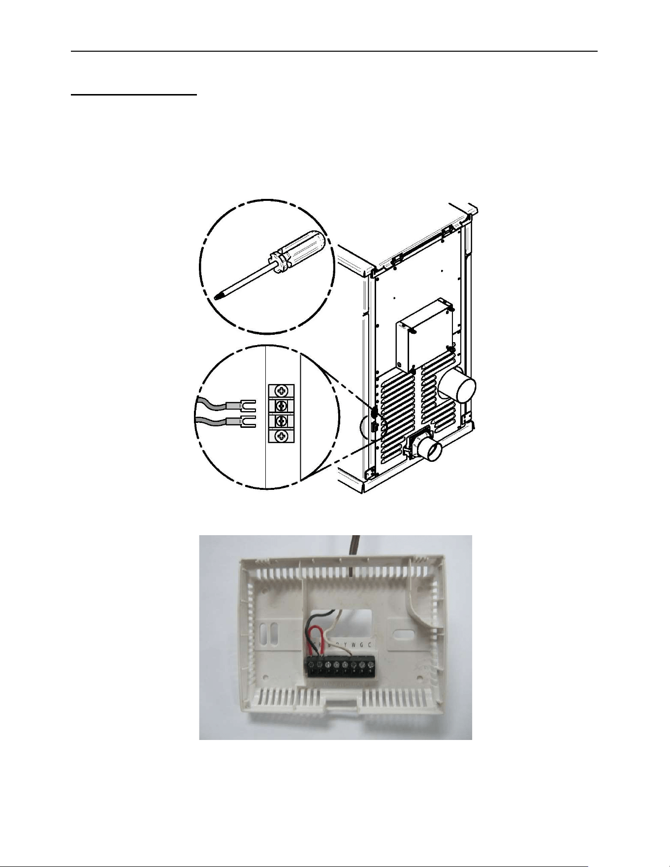
ECO-65R Installation and Operation Manual
93
Wired thermostat
Before installing the thermostat, unplug the power cord from the power outlet.
First, connect the two thermostat wires to the terminal block located at the rear on the right-
hand side of the stove when facing it. Loosen the two middle screws and insert the wires in
the terminals. Tighten the two screws. Open the thermostat and connect the wires as per
the manufacturer’s instructions.
Here is an example of what your thermostat could look like:
Connect one wire on “RH” and the other wire on “W”. Red wire jumper can remain installed.
For further information refer to the manufacturer’s instructions.
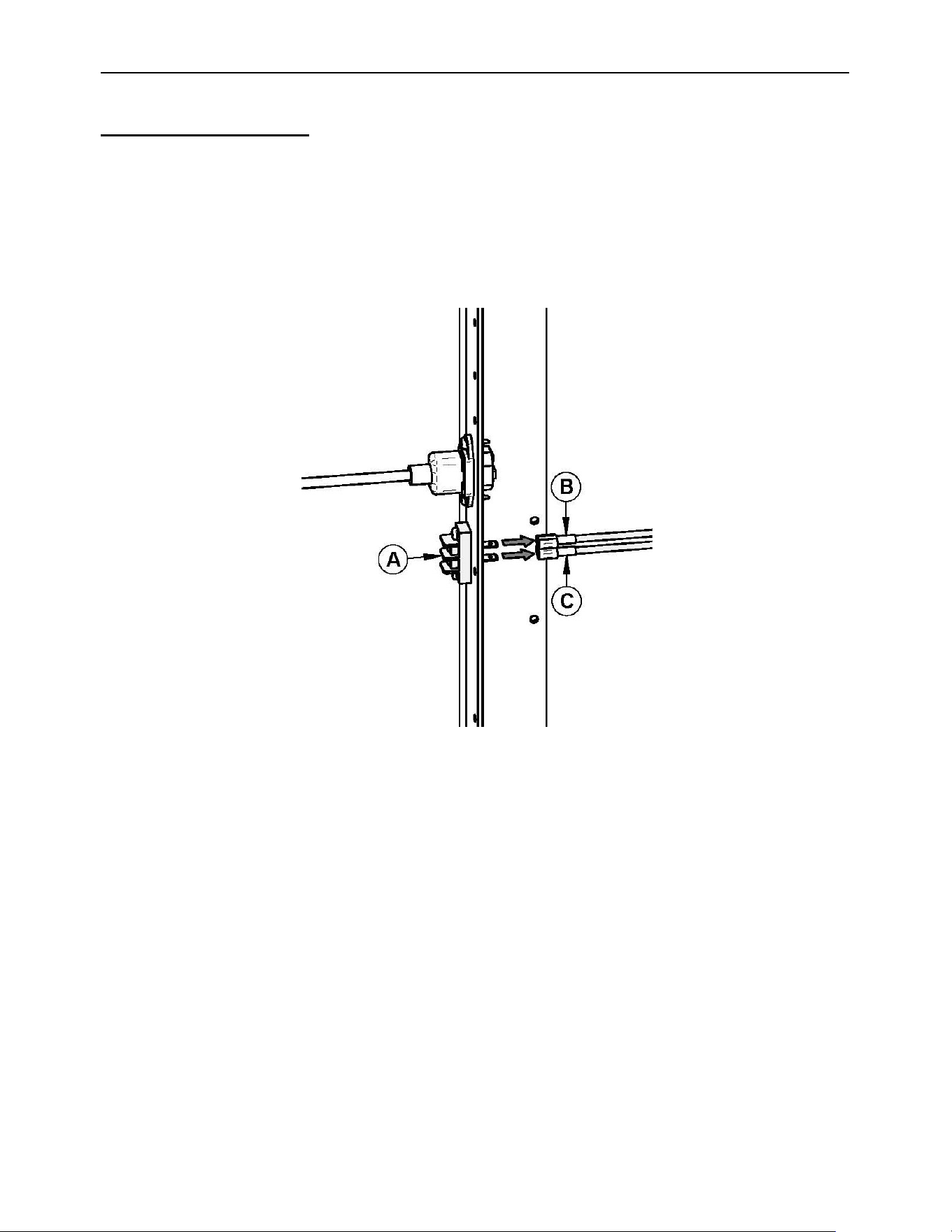
ECO-65R Installation and Operation Manual
94
Wireless thermostat
If you are using a wireless thermostat or a handheld thermostatic remote control, connect
the two thermostat wires to the terminal block located at the rear on the right-hand side of
the stove while facing it. If the receiver wires are equipped with quick-connect terminals you
can connect them directly to the stove’s wiring harness.
To do so, open the right-hand side decorative panels and disconnect wires (B) and (C)
attached to the rear of the terminal block (A) and connect them to the receiver.
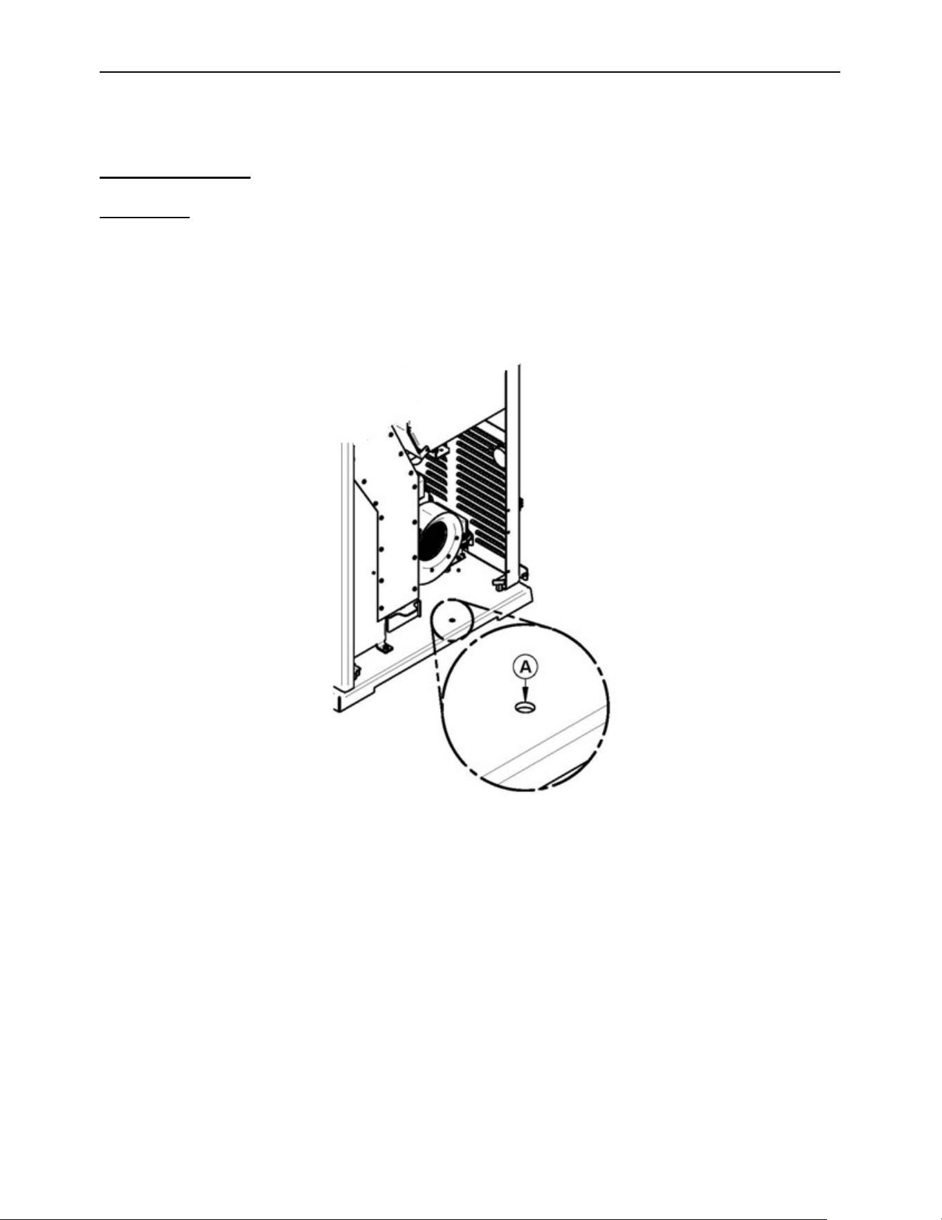
ECO-65R Installation and Operation Manual
95
APPENDIX C: MOBILE HOME INSTALLATION
Anchor the stove
WARNING: FOR MOBILE HOME INSTALLATION, IT IS MANDATORY TO CONNECT
THE STOVE TO AN OUTSIDE COMBUSTION AIR SOURCE. (SEE APPENDIX D:
COMBUSTION AIR SUPPLY).
When installed in a mobile home, the stove must be anchored to the floor with two screws.
Use the two anchoring holes (A) located for this purpose on each side of the pedestal, as
shown on the following image.
For use in a mobile home in Canada, this pellet stove must be connected to a vent system
certified according to the standard or ULC/ORD-C441 CAN/ULC-S609. A vent system
meeting the requirements of ULC S629M can also be used.
For use in a manufactured home in the United States, this pellet stove must be connected
to a venting system that meets the requirements of UL 641 standard. A vent system that
meets the requirements of UL 103 standard may also be used.
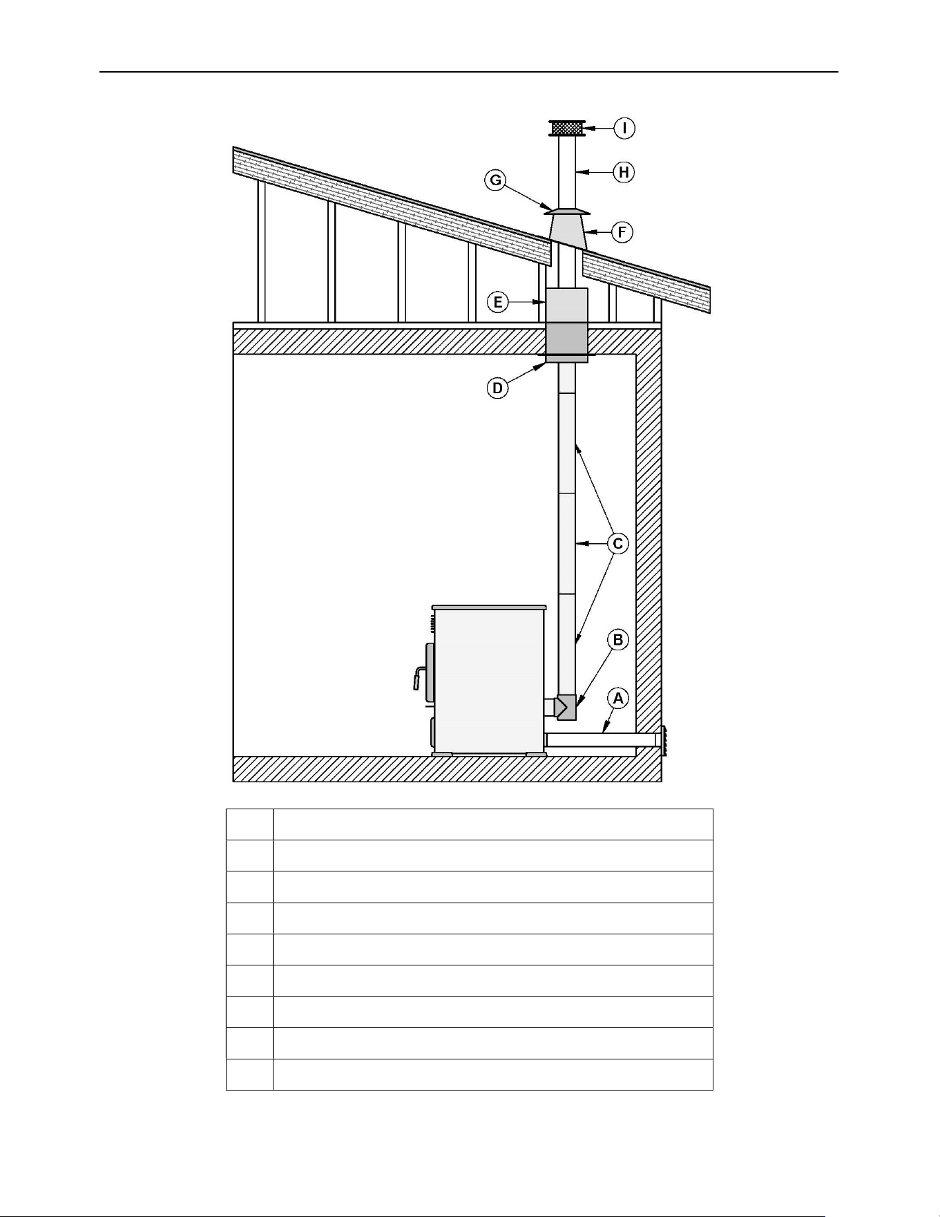
ECO-65R Installation and Operation Manual
96
A Fresh air intake
B T
C Pellet pipe length and/or slip section
D Ceiling support
E Attic insulation shield
F Roof flashing
G Storm collar
H Pellet pipe length
I Vertical rain cap
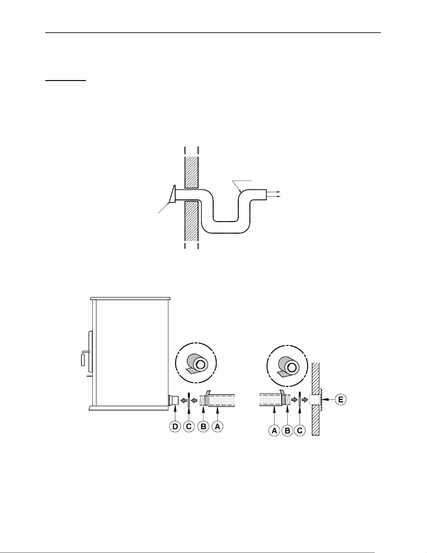
ECO-65R Installation and Operation Manual
97
APPENDIX D: COMBUSTION AIR SUPPLY
WARNING: FOR MOBILE HOME INSTALLATION, IT IS MANDATORY TO CONNECT
THE STOVE TO AN OUTSIDE COMBUSTION AIR SOURCE. INSULATED PIPE SHOULD
NEVER EXCEED 10 FEET.
It is recommended to install an outside air inlet in or near the room where the stove is
installed. When doing so, it is preferable to choose a wall which is not exposed to dominant
winds, depending on the conditions surrounding your house.
An insulated 3” inside diameter metallic pipe, either flexible or rigid, must be attached to the
fresh air intake (D).
To complete the installation, make a hole of 1/4" to 1/2" (6 mm à 13 mm) bigger than the
insulate pipe diameter in the outside wall of the house at the chosen location. From outside,
place the outside air inlet cap (E) in the hole (open side down) and fasten the register to the
wall, with screw. Place the insulated pipe (A) over the register tube and over the fireplace
outside air connector (D). At each end, carefully pull back the insulation and plastic cover,
AIR SUPPLY
INSULATED PIPE
EXTERIOR WALL
AIR INLET
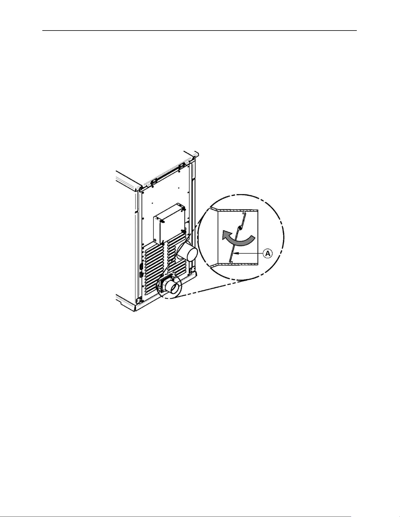
ECO-65R Installation and Operation Manual
98
exposing the flexible pipe. Attach the flexible pipe using pipe clamps (C). For a better seal,
you may also use aluminum tape. Wrap the tape around the joint between the flexible pipe
and the air inlets. Carefully push the insulation and plastic cover back over the pipe. Fix the
plastic in place using aluminum tape.
A rodent guard (minimum 1/4” wire mesh) must be used at the termination. All connections
must be secured and airtight by either using the appropriately sized hose clamp and/or UL-
181-AP foil tape.
Make sure that the fresh air intake back draft shutter (A) functions freely. The fresh air intake
back draft shutter is located in the back of the stove.
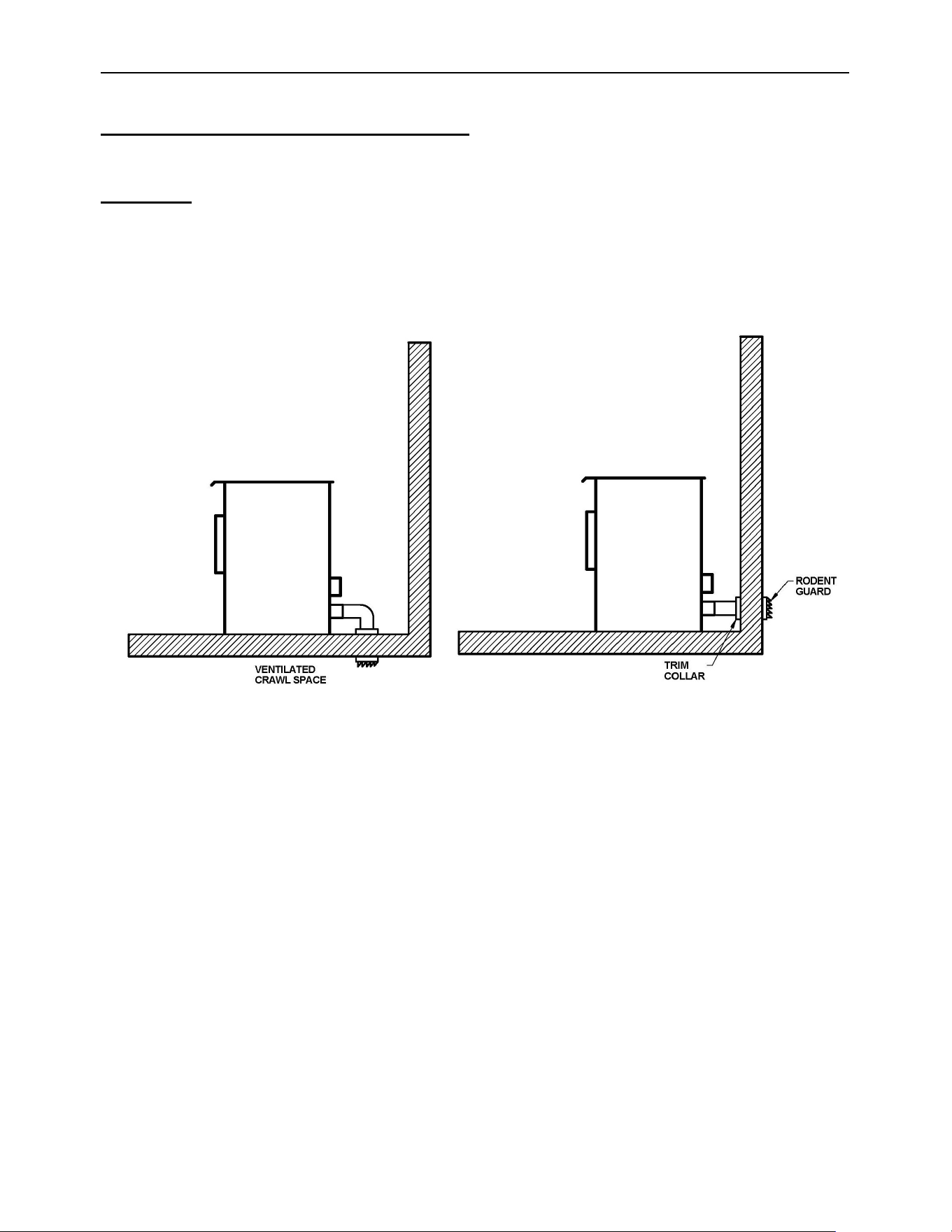
ECO-65R Installation and Operation Manual
99
Sources of Outside Combustion Air
WARNING: IT IS FORBIDDEN TO DRAW COMBUSTION AIR FROM A BASEMENT, AN
ATTIC, A GARAGE OR ANY CONFINED SPACE.
You can draw air from a ventilated crawl space underneath the floor.
You can draw air directly from an outside wall, behind the stove.
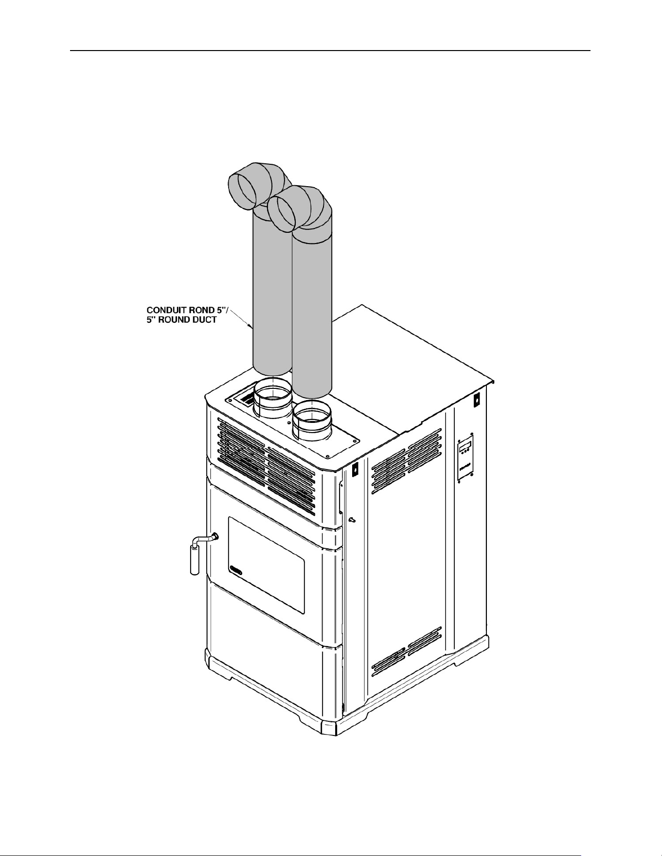
ECO-65R Installation and Operation Manual
100
APPENDIX E: OPTIONAL HOT AIR PLENUM KIT (AC01225)
The hot air plenum kit AC01225 is available at your local dealer.
Note that the 5-inch round ducts required to complete the installation are sold separately.
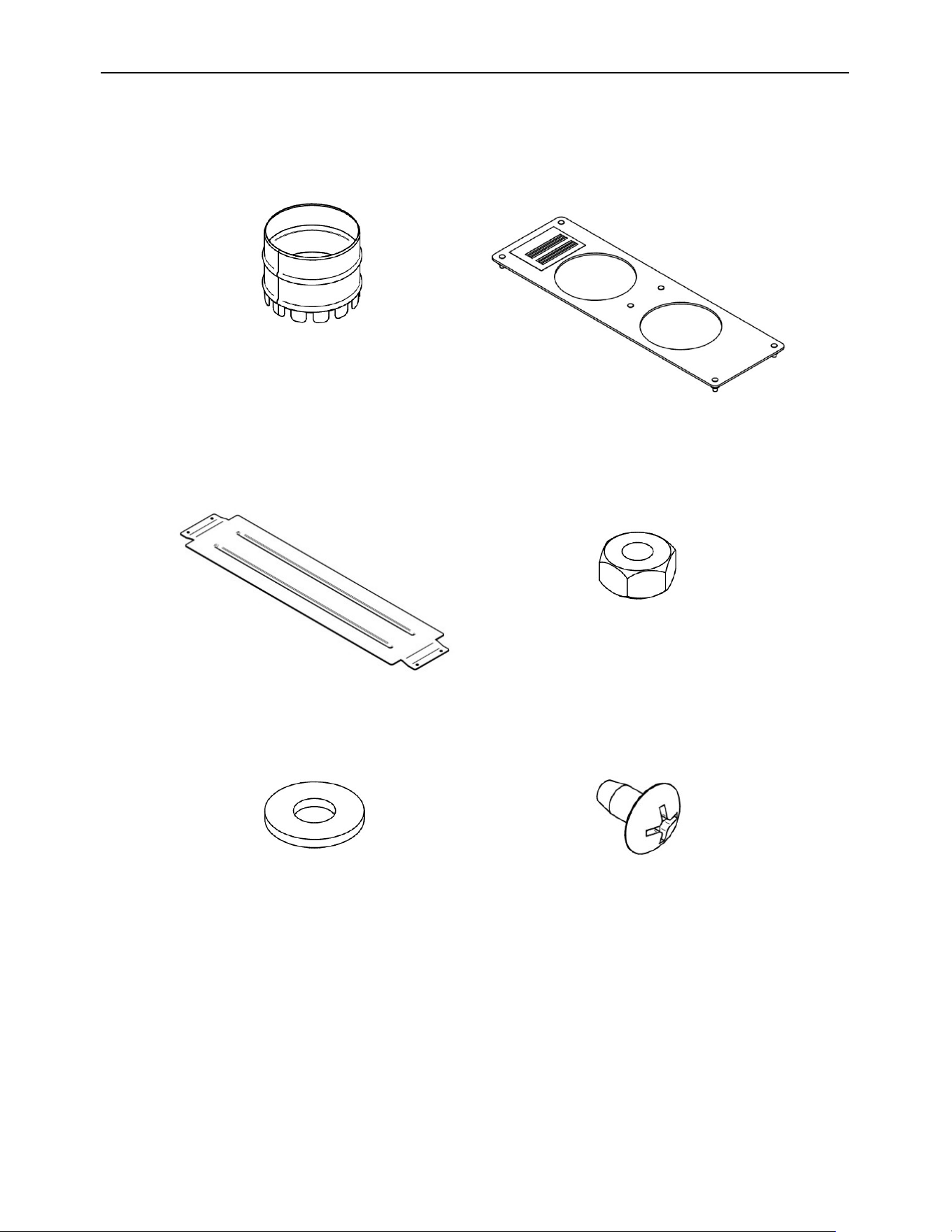
ECO-65R Installation and Operation Manual
101
This hot air plenum kit contains the following parts:
(A) -PL66837
2x
(B) -PL75648
1x
(C) -PL75671
1x
(D) -30100
6x
(E) -30185
6x
(F)-31054
4x
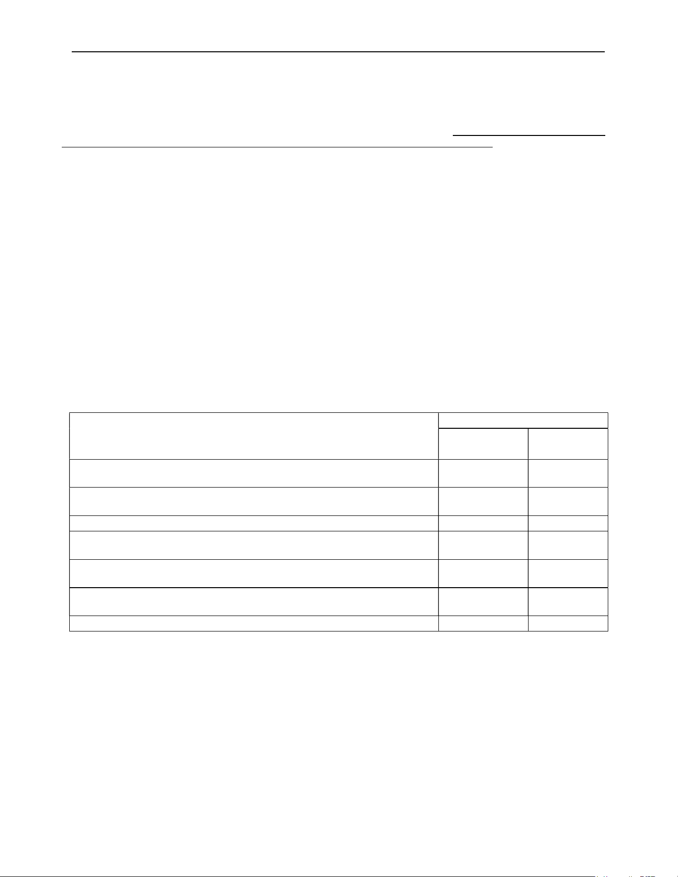
ECO-65R Installation and Operation Manual
102
DROLET LIMITED LIFETIME WARRANTY
The warranty of the manufacturer extends only to the original retail purchaser and is not transferable. This warranty covers brand new
products only, which have not been altered, modified nor repaired since shipment from factory. Proof of purchase (dated bill of sale),
model name and serial number must be supplied when making any warranty claim to your DROLET dealer.
This warranty is void if the unit is used to burn materials other than wood pellet (for which the unit is not certified by the EPA)
and void if not operated according to the owner’s manual. This warranty applies to normal residential use only. Damages caused
by misuse, abuse, improper installation, lack of maintenance, over firing, negligence or accident during transportation, power
failures, downdrafts, venting problems or under-estimated heating area are not covered by this warranty. The recommended
heated area for a given appliance is defined by the manufacturer as its capacity to maintain a minimum acceptable temperature
considering that the space configuration and the presence of heat distribution systems have a significant impact in making heat
circulation optimum.
This warranty does not cover any scratch, corrosion, distortion, or discoloration. Any defect or damage caused by the use of unauthorized
or other than original parts void this warranty. An authorized qualified technician must perform the installation in accordance with the
instructions supplied with this product and all local and national building codes. Any service call related to an improper installation is not
covered by this warranty.
The manufacturer may require that defective products be returned or that digital pictures be provided to support the claim. Returned
products are to be shipped prepaid to the manufacturer for investigation. Transportation fees to ship the product back to the purchaser
will be paid by the manufacturer. Repair work covered by the warranty, executed at the purchaser’s domicile by an authorized qualified
technician requires the prior approval of the manufacturer. All parts and labour costs covered by this warranty are limited according to
the table below.
The manufacturer, at its discretion, may decide to repair or replace any part or unit after inspection and investigation of the defect. The
manufacturer may, at its discretion, fully discharge all obligations with respect to this warranty by refunding the wholesale price of any
warranted but defective parts. The manufacturer shall, in no event, be responsible for any uncommon, indirect, consequential damages of
any nature, which are in excess of the original purchase price of the product. A one-time replacement limit applies to all parts benefiting
from lifetime coverage. This warranty applies to products purchased after March 1
st
, 2015.
DESCRIPTION
WARRANTY APPLICATION*
PARTS LABOUR
Combustion chamber (welds only**), heat exchanger (welds only**), and cast-
iron door frame.
Lifetime 3 years
Surrounds, heat shields, ash drawer, legs, pedestal, trims (aluminum
extrusions), and plating (defective manufacture**).
5 years 3 years
Removable stainless-steel components, burn pot, deflectors, and supports. 3 years N/A
Glass retainers, handle assembly, cleaning rod, air control mechanism, and
auger.
3 years 1 year
Blowers, auger motor, PC board, igniter, heat sensors, switches, wiring,
rheostat, and other controls.
1 year 1 year
Ceramic glass (thermal breakage only**), paint (peeling**), gaskets, insulation,
ceramic fibre blankets, ceramic logs, masonry-like panels and other options.
1 year N/A
All parts replaced under the warranty. 90 days N/A
*Subject to limitations above. **Picture required.
Labour cost and repair work to the account of the manufacturer are based on a predetermined rate schedule and must not exceed the
wholesale price of the replacement part.
Shall your unit or a component be defective, contact immediately your DROLET dealer. To accelerate processing of your warranty
claim, make sure to have on hand the following information when calling:
Your name, address and telephone number.
Bill of sale and dealer’s name.
Installation configuration;
Serial number and model name as indicated on the
nameplate fixed to the back of your unit.
Nature of the defect and any relevant information.
Before shipping your unit or defective component to our plant, you must obtain an Authorization Number from your DROLET
dealer. Any merchandise shipped to our plant without authorization will be refused automatically and returned to sender.