READ AND KEEP THIS MANUAL FOR REFERENCE
Printed in Canada
46240_A
2021-09-17
MOBILE
HOME
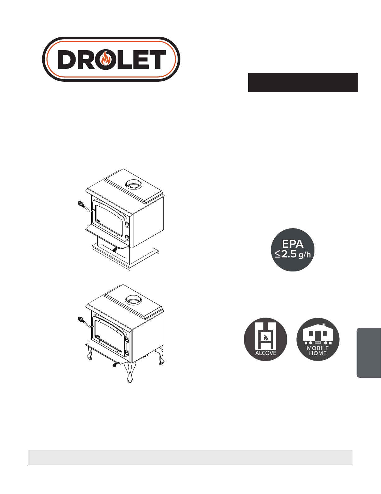
Safety tested according to ULC S627,
UL 1482 and UL 737 standards by an
accredited laboratory.
US Environmental Protection Agency
phase II certified wood stove compliant
with 2020 cord wood standard
CONTACT LOCAL BUILDING OR FIRE OFFICIALS ABOUT RESTRICTIONS AND INSTALLATION INSPECTION REQUIREMENTS
IN LOCAL AREA.
READ THIS ENTIRE MANUAL BEFORE INSTALLATION AND USE OF THIS WOOD STOVE. FAILURE TO FOLLOW THESE
INSTRUCTIONS COULD RESULT IN PROPERTY DAMAGE, BODILY INJURY OR EVEN DEATH.
ENGLISH
Wood Stove
Owner's Manual
Part 2 of 2
INSTALLATION AND OPERATION
REQUIREMENTS
ESCAPE 1800
(modèle DB03102, DB03105, DB03111 et DB03112)

Dealer:
Installer:
Phone Number:
Serial Numbrer:
ONLINE WARRANTY REGISTRATION
If the unit requires repairs during the warranty period, proof of purchase must be provided. The
purchase invoice must be kept. The date indicated on it establishes the warranty period. If it
cannot be provided, the warranty period will be determined by the date of manufacture of the
product. It is also highly recommended to register the warranty online at
https://www.drolet.ca/en/warranty/warranty-registration/
Registering the warranty will help to quickly nd the information needed on the unit.

Page 3
Installation and Operation Manual - Wood Stove
ENGLISH
TABLE OF CONTENT
1. CERTIFICATION PLATE .......................................................................................................... 4
2. General Information ................................................................................................................ 5
2.1 Performances ..................................................................................................................... 5
2.2 Specifications ..................................................................................................................... 6
2.3 Dimensions ........................................................................................................................ 7
2.3.1 Stove Dimensions with Legs .................................................................................... 7
2.3.2 Dimensions with pedestal ........................................................................................ 8
2.3.3 Combustion Chamber Dimensions ........................................................................... 9
2.4 EPA Loading .....................................................................................................................10
2.4.1 Air control .............................................................................................................10
2.4.2 High burn rate (primary air control open) ..................................................................10
2.4.3 Medium and low burn rate ......................................................................................10
3. Clearances to Combustible Material .................................................................................... 11
3.1 Clearances ........................................................................................................................13
3.1.1 With Heat Shield AC02762 ....................................................................................14
3.1.2 With Lowered Ceiling .............................................................................................15
3.1.3 With Heat Shield AC02762 and Lowered Ceiling ......................................................16
3.1.4 Inside an Alcove ....................................................................................................17
3.1.5 Mobile Home .........................................................................................................17
3.1.6 Mobile Home With Heat Shield AC02762 .................................................................18
4. Floor Protection .................................................................................................................... 19
5. Reducing Wall and Ceiling Clearances Safely .................................................................... 20
5.1 Shield Construction Rules ..................................................................................................20
6. Installation of options on your product ................................................................................ 23
6.1 Decorative Panels ..............................................................................................................23
6.2 Log retainers installation ....................................................................................................24
6.3 Optional Fresh Air Intake Kit Installation ..............................................................................25
6.4 Optional Fire Screen Installation ........................................................................................26
6.5 Optional Blower And Thermodisc Installation .......................................................................27
6.6 Air Tubes And Baffle Installation ..........................................................................................28
6.7 Mobile Home Installation ....................................................................................................30
7. Maintenance/Parts Replacement ......................................................................................... 31
7.1 Replacement .....................................................................................................................31
7.2 Gasket ..............................................................................................................................32
7.3 Door .................................................................................................................................32
7.3.1 Adjustment ............................................................................................................33
7.3.2 Gasket ..................................................................................................................33
7.4 Door alignment ..................................................................................................................34
8. Exploded Diagram and Parts List - with Legs ..................................................................... 35
9. Exploded Diagram and Parts List - with Pedestal............................................................... 38
Page 4
Installation and Operation Manual - Wood Stove
ENGLISH
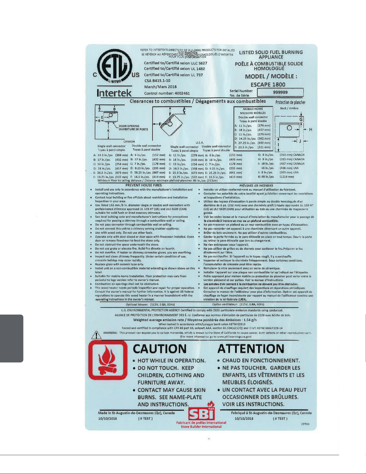
1. CERTIFICATION PLATE
Page 5
Installation and Operation Manual - Wood Stove
ENGLISH
2. General Information
2.1 Performances
Values are as measured per test method, except for the recommended heating area, firebox volume,
maximum burn time and maximum heat output.
Model
Escape 1800
(DB03102, DB03105, DB03111 and DB03112)
Fuel Type
Dry Cordwood
Recommended heating area (sq. ft.
.
)
1
500 to 2,100 ft
2
(47 to 195 m
2
)
Total firebox volume 2.4 ft
3
(0.068 m
3
)
Loading volume EPA
2.02 ft
3
(0.057 m
3
)
Maximum burn time
1
8 hours
Maximum heat output (dry cordwood)
2
75,000 BTU/h (22.0 kW)
Overall heat output rate (min. to max.)
2 3
14,8000 BTU/h to X28,600 BTU/h
(4.34 kW to 8.38 kW)
Average overall efficiency
3
(Dry cordwood)
69 % (HHV)
4
74 % (LVH)
5
Optimum efficiency
6
77 %
Average particulate emissions rate
7
1.54 g/h (EPA / CSA B415.1-10)
8
Average CO
9
89.4 g/h
1
Recommended heating area and maximum burn time may vary subject to location in home, chimney draft,heat loss factors, climate, fuel type
and other variables. The recommended heated area for a given appliance is defined by the manufacturer as its capacity to maintain a minimum
acceptable temperature in the designated area in case of a power failure.
2
The maximum heat output (dry cordwood) is based on a loading density varying between 15 lb/ft
3
and 20 lb/ft
3
. Other performances are based on
a fuel load prescribed by the standard. The specified loading density varies between 7 lb/ft³ and 12 lb/ft
3
. The moisture content is between 19%
and 25%.
3
As measured per CSA B415.1-10 stack loss method.
4
Higher Heating Value of the fuel.
5
Lower Heating Value of the fuel.
6
Optimum overall efficiency at a specific burn rate (LHV).
7
This appliance is officially tested and certified by an independent agency.
8
Tested and certified in compliance with CFR 40 part 60, subpart AAA, section 60.534(a)(1(ii) and ASTM E3053-17. Based on ALT-125 sent by EPA on
February 28th, 2018.
9
Carbon monoxide.
Page 6
Installation and Operation Manual - Wood Stove
ENGLISH
2.2 Specifications
Maximum log length
10
20 in (508 mm) east-west
Flue outlet diameter 6 in (150 mm)
Recommended connector pipe diameter 6 in (150 mm)
Type of chimney ULC-S629, UL 103 HT (2100 °F)
Baffle material Vermiculite
Approved for alcove installation Yes
Approved for mobile home installation
11
Yes
Type of door Single, glass with cast iron frame
Type of glass Ceramic glass
Particulate emission standard
12
EPA / CSA B415.1-10
USA standard (Safety) UL 1482, UL 737
Canada standard (Safety) ULC-S627
10
North-south: ends of the logs visible, East-west: sides of the logs visible.
11
Mobile homes (Canada) or manufactured homes (USA): The US Department of Housing and Urban Development describes “manufactured homes”
better known as “mobile homes” as follows; buildings built on fixed wheels and those transported on temporary wheels/axles and set on a permanent
foundation. In Canada, a mobile home is a dwelling for which the manufacture and assembly of each component is completed or substantially
completed prior to being moved to a site for installation on a foundation and connection to service facilities and which conforms to the CAN/CSA-
Z240 MH standard.
12
Tested and certified in compliance with CFR 40 part 60, subpart AAA, section 60.534(a)(1(ii) and draft ASTM WK47329-14. Based on ALT-125
sent by EPA on February 28th, 2018.
Page 7
Installation and Operation Manual - Wood Stove
ENGLISH
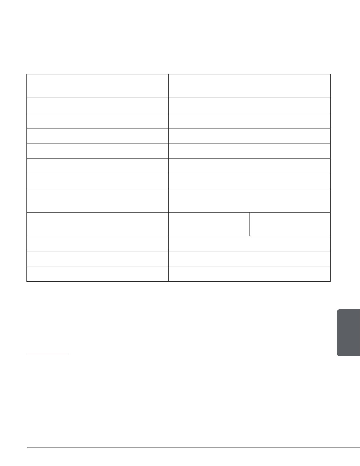
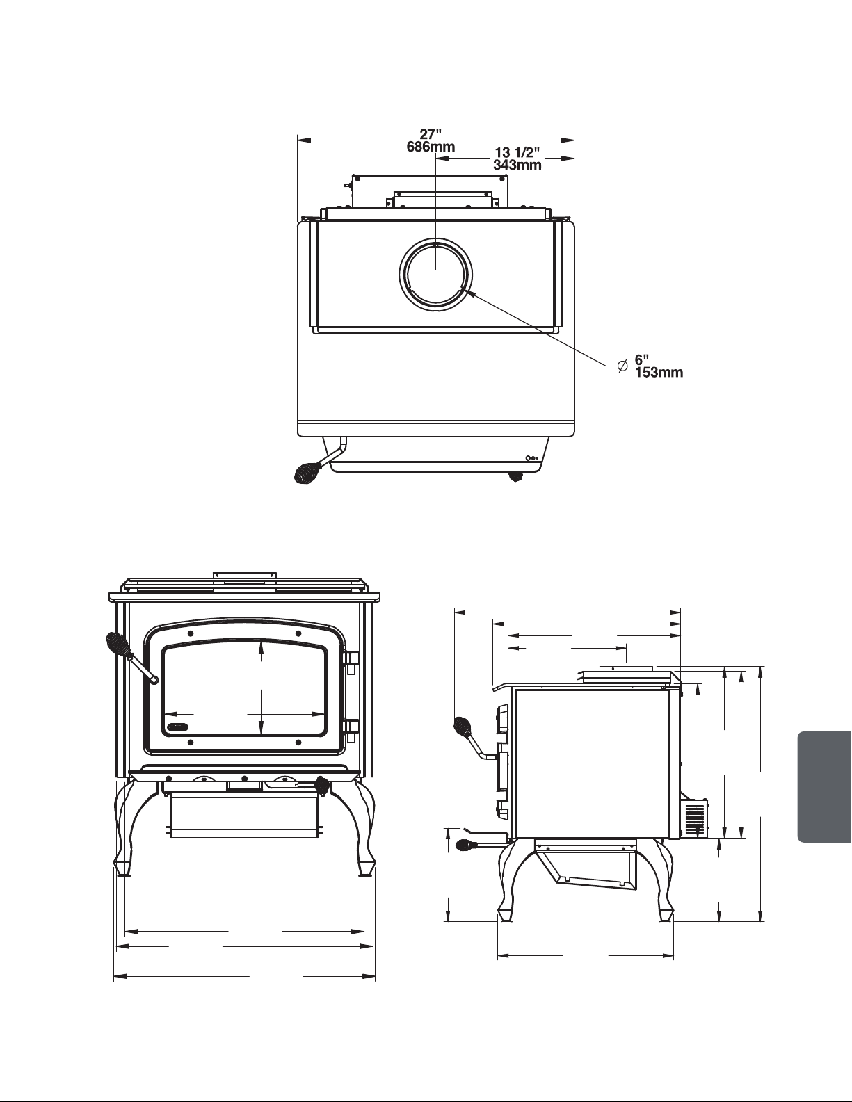
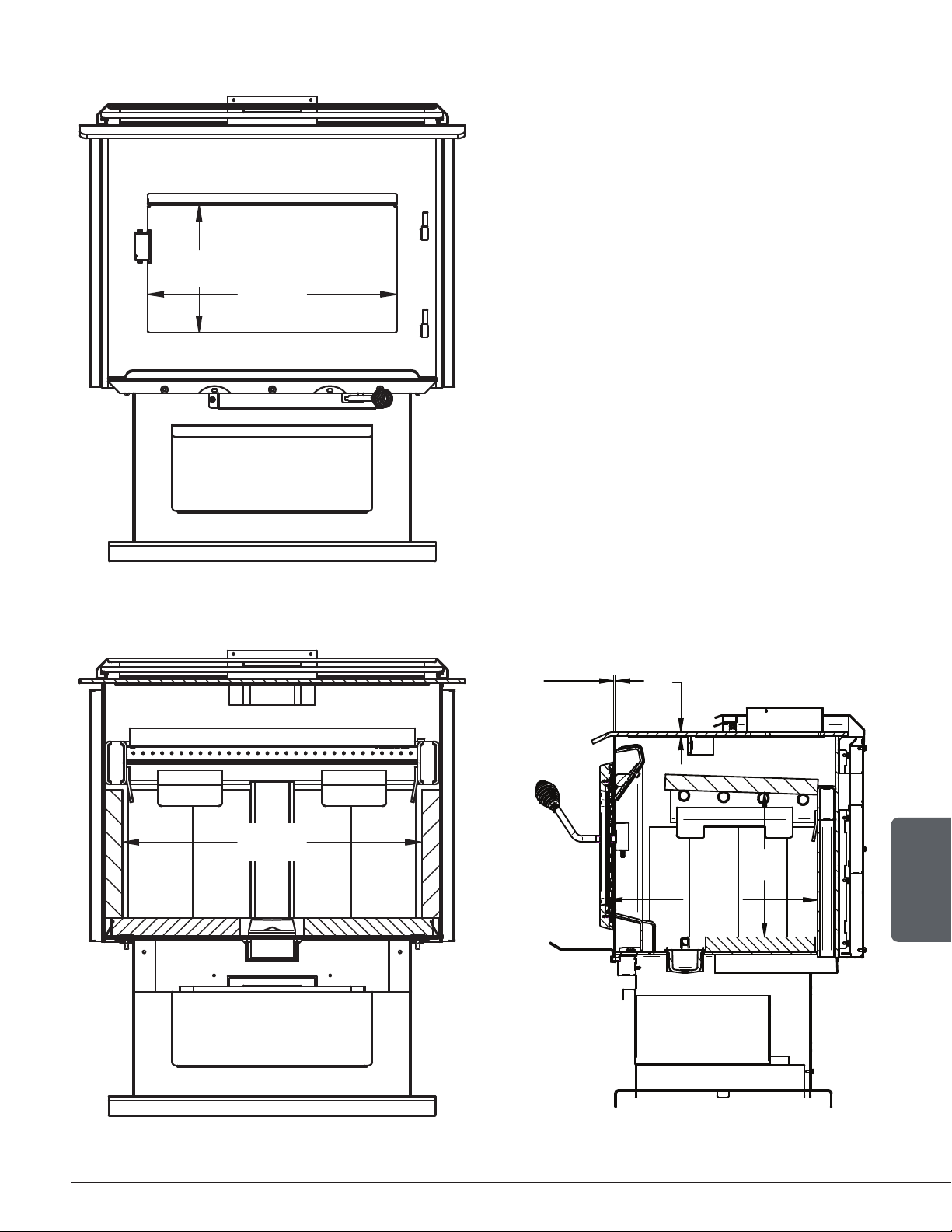
2.3 Dimensions
2.3.1 Stove Dimensions with Legs
Figure 1: Top View
25 5/8"
651mm
26 1/8"
664mm
9 1/4"
235mm
16"
406mm
23 7/8"
606mm
11"
281mm
20 7/8"
530mm
9 7/8"
251mm
18 3/8"
467mm
19 3/4"
503mm
20 3/8"
518mm
30 1/4"
768mm
14"
356mm
20 1/2"
520mm
22 1/4"
566mm
26 7/8"
682mm
Figure 2: Front View Figure 3: Side View
Page 8
Installation and Operation Manual - Wood Stove
ENGLISH
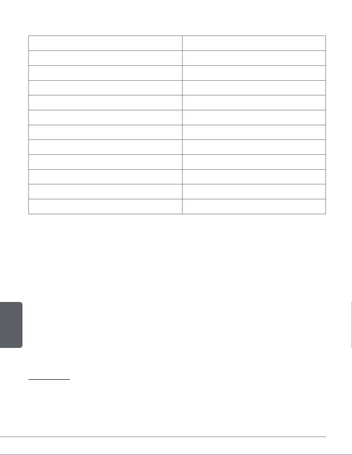
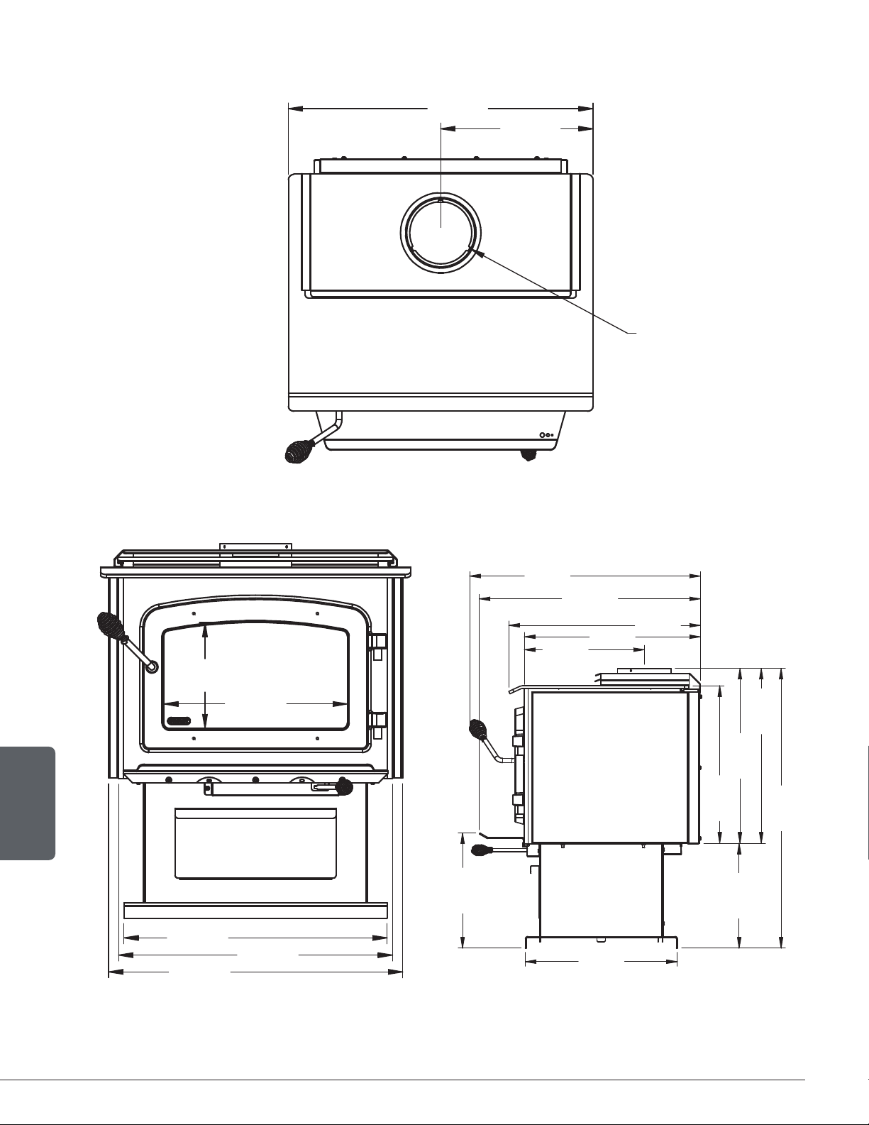
2.3.2 Dimensions with pedestal
13 1/2"
343mm
27"
686mm
O
6"
153mm
Figure 4: Top View
25 5/8"
651mm
22 7/8"
582mm
9 1/4"
235mm
16"
406mm
23 7/8"
606mm
13 3/8"
341mm
17 3/4"
451mm
12 1/4"
311mm
18 3/8"
467mm
20 3/8"
518mm
20 3/8"
518mm
32 5/8"
829mm
14"
356mm
20 1/2"
522mm
22 3/8"
568mm
26 7/8"
684mm
25 13/16"
655mm
Figure 5: Front View Figure 6: Side View
Page 9
Installation and Operation Manual - Wood Stove
ENGLISH
2.3.3 Combustion Chamber Dimensions
9"
227mm
17 1/2"
444mm
Figure 7: Door Opening
21"
533mm
3/16"
5mm
5/16"
8mm
17 1/8"
435mm
11 7/8"
301mm
Figure 8: Front View - Combustion Chamber Figure 9: Side View - Combustion Chamber
Page 10
Installation and Operation Manual - Wood Stove
ENGLISH
2.4 EPA Loading
The loading methods shown below are those that were used during emissions certification.
2.4.1 Air control
The air control is located underneath the ash shelf. To open the air
control, push the air control handle completely to the left (High).
This will increase the burn rate. To close the air control, push the
air control handle completely to the right (Low). This will decrease
the burn rate.
2.4.2 High burn rate (primary air control open)
Open the air control completely. Place six small pieces (2"x2") of wood in the firebox crossing
them at the greatest possible angle. Criss cross fifteen kindling wood pieces on the small pieces
of wood in three layers at the greatest possible angle. Tie knot with five sheets of paper and
place them on top of the kindling wood. Light up the paper and let the door ajar at 90° until all
the kindling wood is on fire and the first row of small pieces of wood is on fire too. Close the
door.
When there is no more fire in the front of the firebox and there are only faint flames on the wood
in the back of the firebox, break ashes, level the coal bed and put four logs in the firebox. Place
the biggest log (about 5"x5") and a medium log (about 4"x4") on the coal bed with a north-south
orientation. Place two other medium logs on the first two with the greatest possible angle. Their
should be air space between each logs and between the logs and the bricks. Let the door ajar
at 90° for approximately two minutes and then close the door.
2.4.3 Medium and low burn rate
On a 2" coal bed that is still slightly red, place five logs of approximatively 4"x4" or 3"x3" with
a north-south orientation. Place three logs on the coal bed and the other two on top with the
greatest possible angle. Their should be air space between each logs and between the logs
and the bricks. Let the door ajar at 90° for approximately 5 min. Then, close the door with the
primary air control open. Leave to burn with the primary air control open for approximately 10
minutes and then close the primary air control completely for the low burn rate and halfway for
the medium burn rate.
+
—

Page 11
Installation and Operation Manual - Wood Stove
ENGLISH
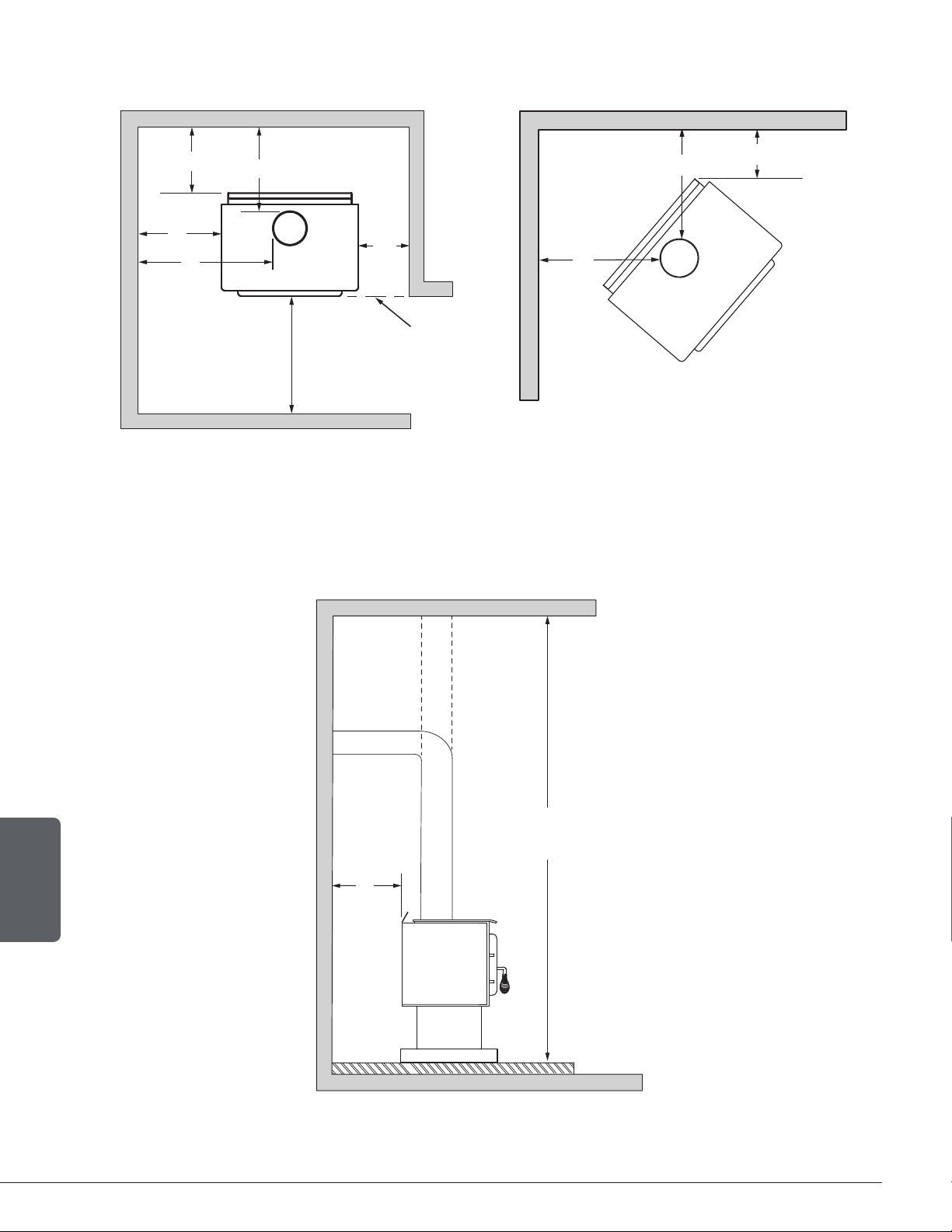
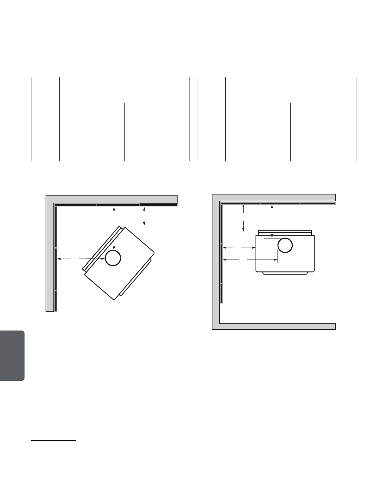
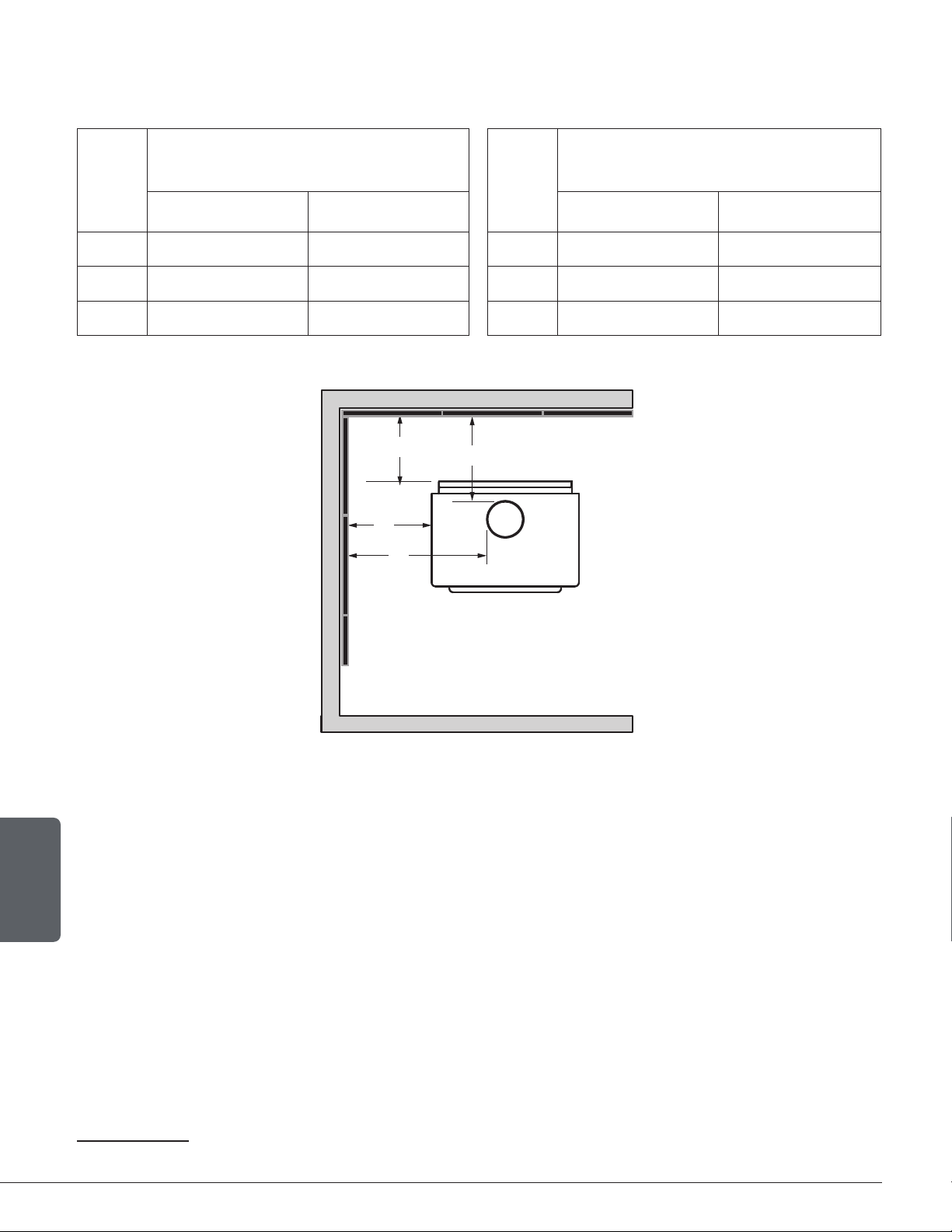
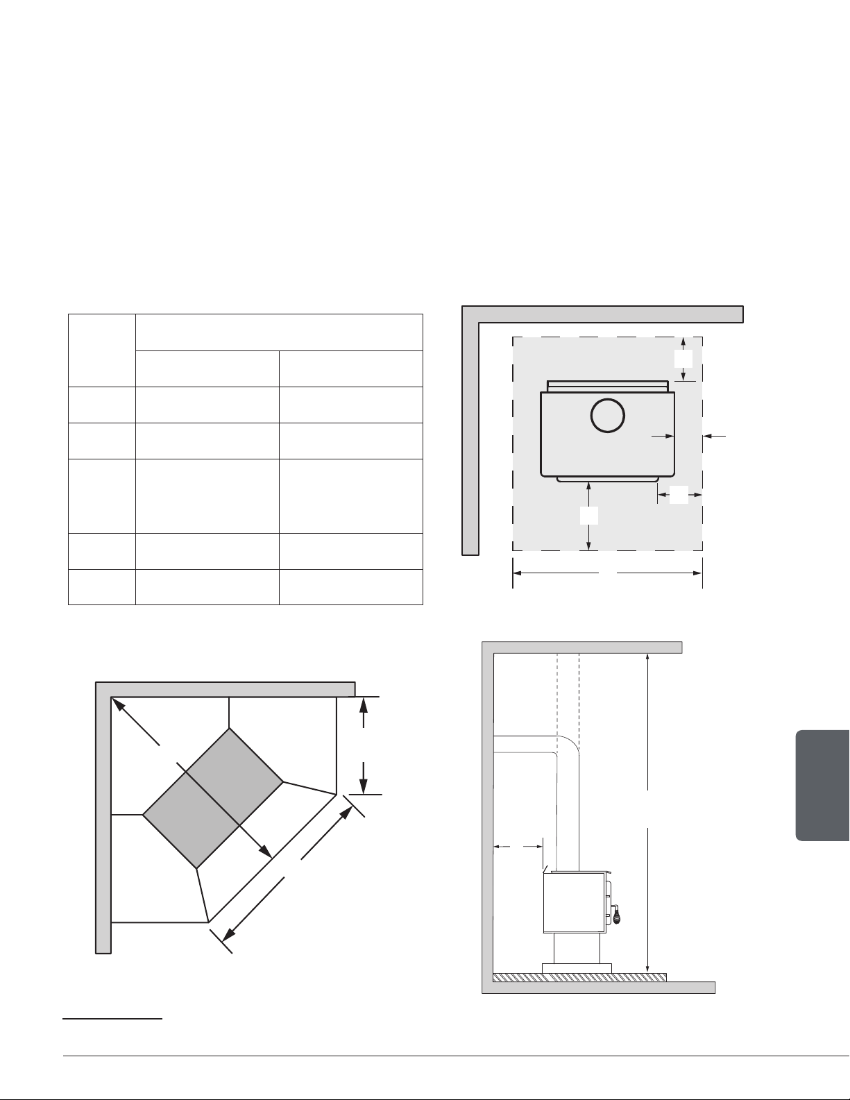
3. Clearances to Combustible Material
The clearances shown in this section have been determined by tests according to procedures
set out in safety standards ULC S627 (Canada), UL 1482 (U.S.A.) and UL 737 (U.S.A.). When
the stove is installed so that its surfaces are at or beyond the minimum clearances specified,
combustible surfaces will not overheat under normal and even abnormal operating conditions.
No part of the stove or flue pipe may be located closer to combustibles than the minimum
clearance figures given.
The clearances to combustible walls may be slightly different in Canada and the U.S.A. and may
also differ depending on whether single or double wall flue pipe is used. Make sure to choose
the correct clearance for the stove location and type of flue pipe.
The clearances of the appliance and the flue pipes must be met individually, meaning the appliance
cannot be installed closer to the combustible materials than the single or double wall pipe allows.
For a safe way to reduce clearances refer to section"5. Reducing Wall and Ceiling Clearances Safely".
Page 12
Installation and Operation Manual - Wood Stove
ENGLISH
A
B
E
D
CAN
48"
122 cm
US
36"
92 cm
48"
Flush
F
F
C
Figure 10: Clearances - Top Figure 11: Clearances - Corner
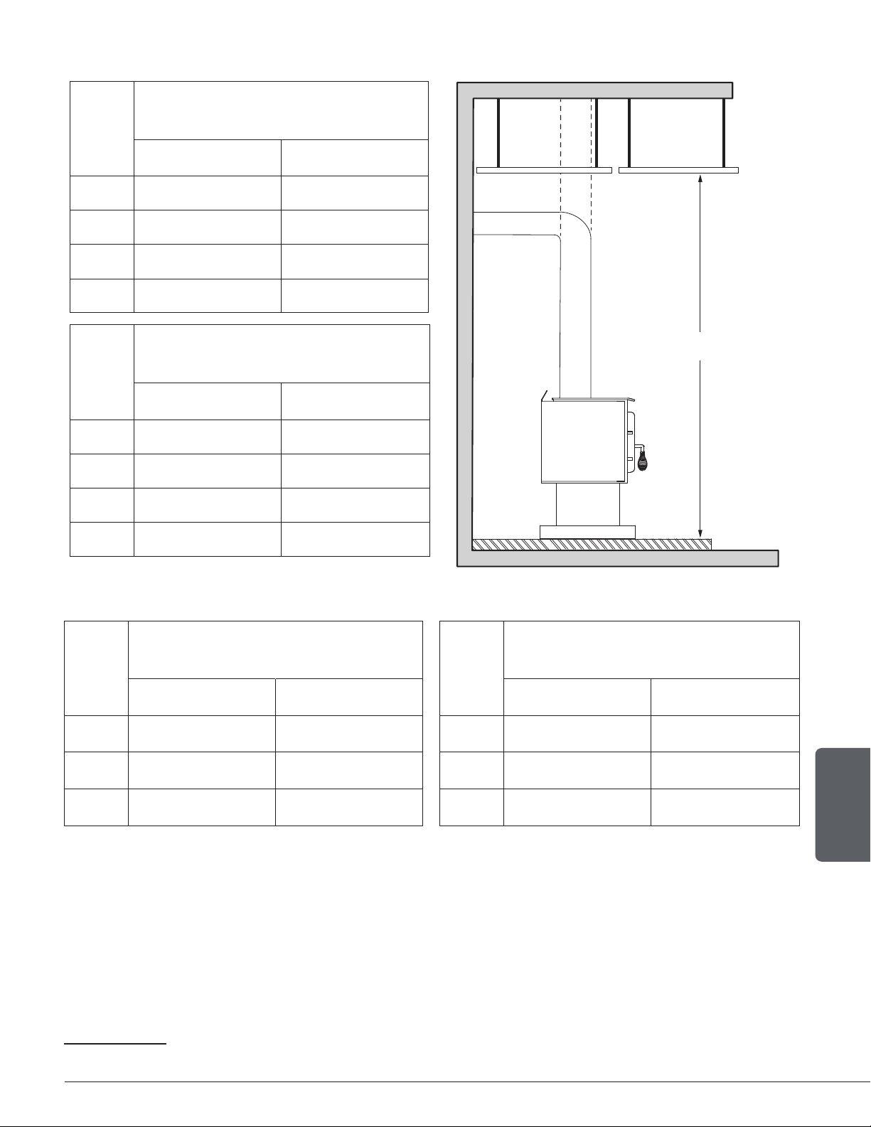
84"
213 cm
Ve
Ho
N
Figure 12: Clearances - Side
Page 13
Installation and Operation Manual - Wood Stove
ENGLISH
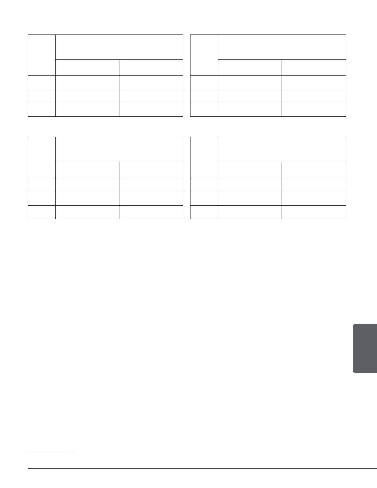
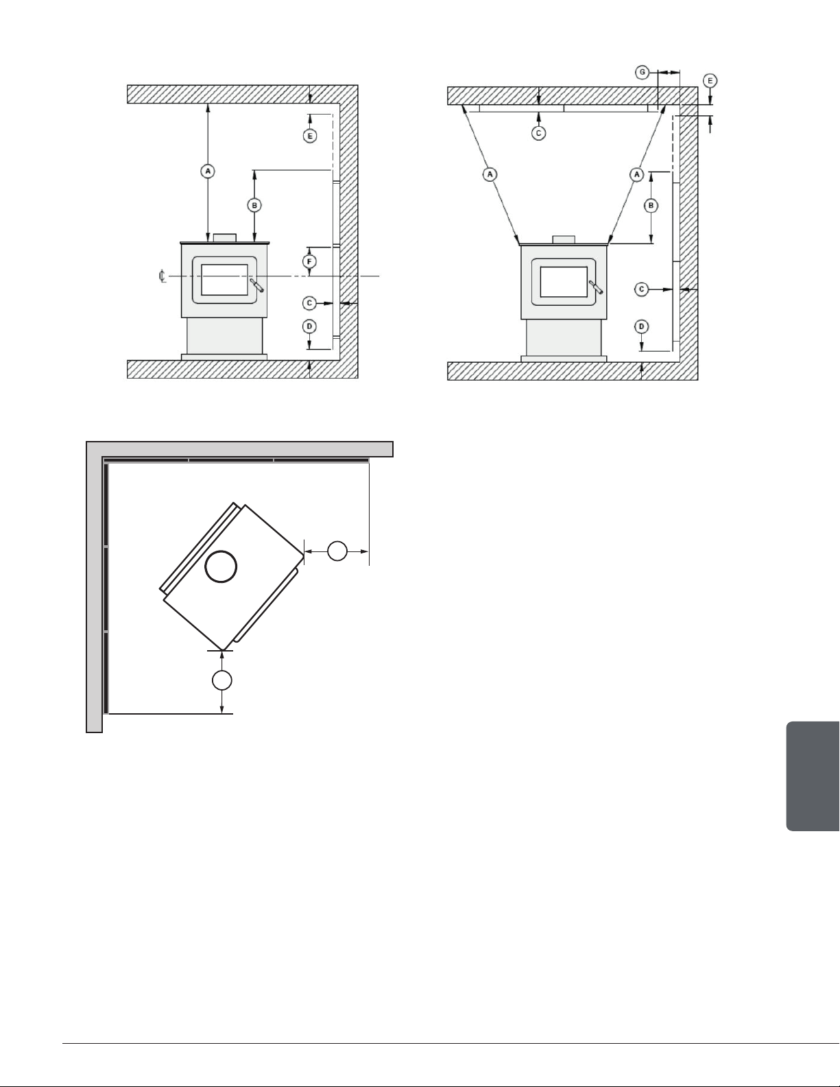
3.1 Clearances
APPLIANCE CLEARANCES WITH SINGLE
WALL PIPE CONNECTOR
APPLIANCE CLEARANCES WITH DOUBLE
WALL PIPE CONNECTOR
Canada USA Canada USA
A 14 ½" (368 mm) 11" (279 mm) A 6" (152 mm) 6" (152 mm)
B 17" (432 mm) 16" (406 mm) B 17" (432 mm) 16" (406 mm)
C 10" (254 mm) 10" (254 mm) C 7" (178 mm) 7" (178 mm)
If the above clearances are met, then the distances measured from the flue outlet will be:
DISTANCES
13
FROM PIPE CONNECTOR
WITH SINGLE WALL PIPE CONNECTOR
DISTANCES¹³ FROM PIPE CONNECTOR
WITH DOUBLE WALL PIPE CONNECTORE
Canada USA Canada USA
D 18" (457 mm) 14 ½" (368 mm) D 9 ¼" (235 mm) 9 ¼" (235 mm)
E 26 ½" (673 mm) 25 ½" (648 mm) E 26 ¼" (667 mm) 25 ¼" (641 mm)
F 19 ¾" (502 mm) 19 ¾" (502 mm) F 16 ½" (419 mm) 16 ½" (419 mm)
13
The pipe distances listed in this table refer to the distances obtained when the stove is installed in accordance with the appliance clearances
above mentioned.
Page 14
Installation and Operation Manual - Wood Stove
ENGLISH
3.1.1 With Heat Shield AC02762
14
To reduce the clearances of an appliance using a single wall pipe connector, the use of a heat
shield certified with the single wall pipe connector to be used as close as 6" from combustible
materials must be used. Only in this case, the same clearances as a certified double wall pipe
connector can be used. Refer to the booklet in the screen options to obtain the dimensions to
be respected.
APPLIANCE CLEARANCES WITH DOUBLE
WALL PIPE CONNECTOR
DISTANCES
15
FROM DOUBLE WALL PIPE
CONNECTOR
Canada USA Canada USA
A 3" (76 mm) 3" (76 mm) D 6 ¼" (159 mm) 6 ¼" (159 mm)
B 4" (102 mm) 4" (102 mm) E 13 ¼" (337 mm) 13 ¼" (337 mm)
C 3" (76 mm) 3" (76 mm) F 12 ½" (318 mm) 12 ½" (318 mm)
F
F
C
A
B
E
D
14
Note that to reduce the clearances of an appliance using a single wall pipe connector, the use of a heat shield certified with the single wall pipe
connector to be used as close as 6" from combustible materials must be used. Only in this case, the same clearances as a certified double wall
pipe connector can be used.
15
The pipe distances listed in this table refer to the distances obtained when the stove is installed in accordance with the appliance clearances above
mentioned.
Page 15
Installation and Operation Manual - Wood Stove
ENGLISH
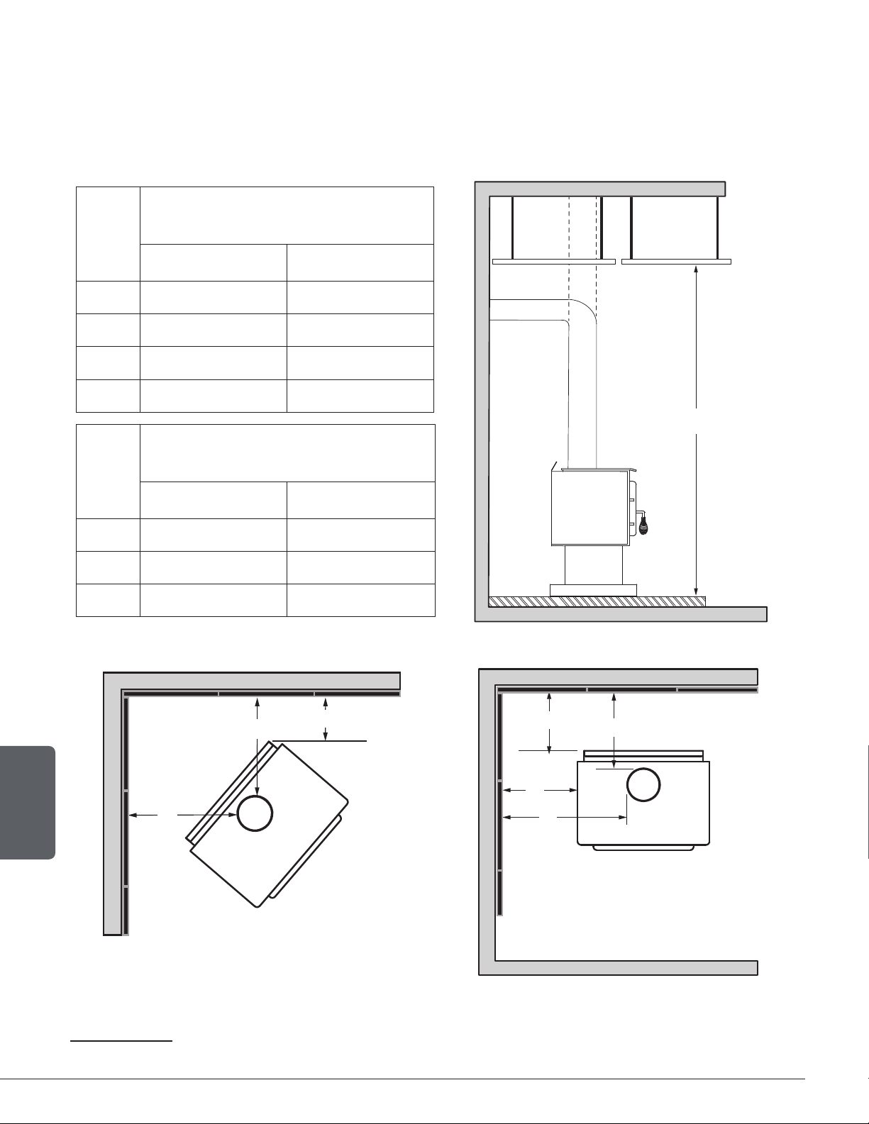
3.1.2 With Lowered Ceiling
APPLIANCE CLEARANCES WITH SINGLE
WALL PIPE CONNECTOR
Canada USA
A 14 ½" (368 mm) 11" (279 mm)
B 19" (483 mm) 18" (457 mm)
C 10" (254 mm) 10" (254 mm)
L 77" ( 1956 mm) 77" ( 1956 mm)
Ve
Ho
L
APPLIANCE CLEARANCES WITH DOUBLE
WALL PIPE CONNECTOR
Canada USA
A 9" (229 mm) 9" (229 mm)
B 19" (483 mm) 19" (483 mm)
C 7" (178 mm) 7" (178 mm)
L 77" (1956 mm) 77" (1956 mm)
If the above clearances are met, then the distances measured from the flue outlet will be:
DISTANCES
16
FROM PIPE CONNECTOR
WITH SINGLE WALL PIPE CONNECTOR
DISTANCES
17
FROM PIPE CONNECTOR
WITH DOUBLE WALL PIPE CONNECTOR
Canada USA Canada USA
D
18" (457 mm) 14 ½" (368 mm)
D
12 ¼" (311 mm) 12 ¼" (311 mm)
E
28 ½" (724 mm) 27 ½" (699 mm)
E
28 ¼" (718 mm) 28 ¼" (718 mm)
F
19 ¾" (502 mm) 19 ¾" (502 mm)
F
16 ½" (419 mm) 16 ½" (419 mm)
16
The pipe distances listed in this table refer to the distances obtained when the stove is installed in accordance with the appliance clearances
above mentioned.
Page 16
Installation and Operation Manual - Wood Stove
ENGLISH
3.1.3 With Heat Shield AC02762 and Lowered Ceiling
To reduce the clearances of an appliance using a single wall pipe connector, the use of a heat
shield certified with the single wall pipe connector to be used as close as 6" from combustible
materials must be used. Only in this case, the same clearances as a certified double wall pipe
connector can be used. Refer to the booklet in the screen options to obtain the dimensions to
be respected.
APPLIANCE CLEARANCES WITH DOUBLE
WALL PIPE CONNECTOR
Canada USA
A
5" (127 mm) 5" (127 mm)
B
6" (152 mm) 6" (152 mm)
C
5" (127 mm) 5" (127 mm)
L
80" (2032 mm) 80" (2032 mm)
Ve
Ho
L
DISTANCES
17
FROM PIPE CONNECTOR
WITH DOUBLE WALL PIPE CONNECTOR
Canada USA
D
8 ¼" (210 mm) 8 ¼" (210 mm)
E
15 ¼" (387 mm) 15 ¼" (387 mm)
F
14 ½" (368 mm) 14 ½" (368 mm)
F
F
C
A
B
E
D
17
The pipe distances listed in this table refer to the distances obtained when the stove is installed in accordance with the appliance clearances
above mentioned.
Page 17
Installation and Operation Manual - Wood Stove
ENGLISH
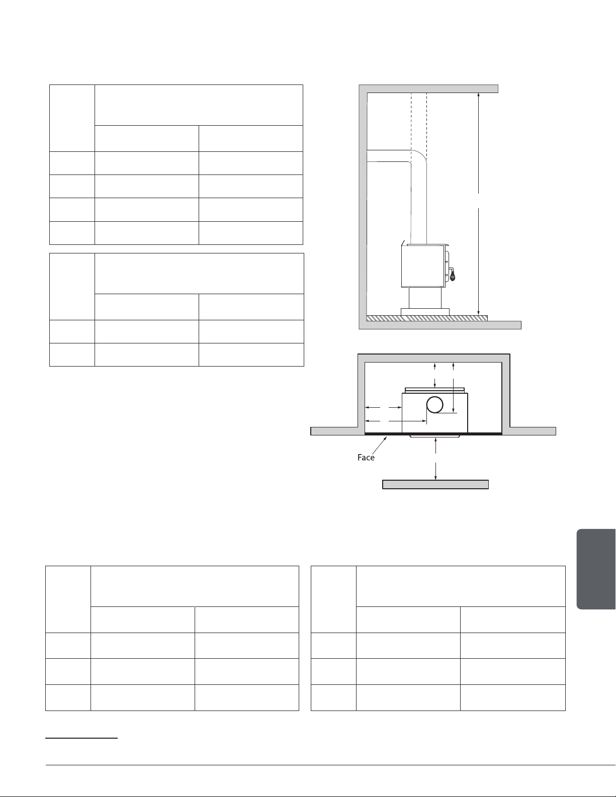
3.1.4 Inside an Alcove
See section 3.1 for the single wall pipe installation.
APPLIANCE CLEARANCES WITH DOUBLE
WALL PIPE CONNECTOR
Canada USA
A
9" (229 mm) 9" (229 mm)
B
19" (483 mm) 19" (483 mm)
K
48" (1219 mm) 48" (1219 mm)
L
77" (1956 mm) 77" (1956 mm)
Ve
Ho
L
DISTANCES
19
FROM PIPE CONNECTOR
WITH DOUBLE WALL PIPE CONNECTOR
Canada USA
D
12 ¼" (311 mm) 12 ¼" (311 mm)
E
28 ¼" (718 mm) 28 ¼" (718 mm)
A
B
E
D
K
3.1.5 Mobile Home
It is strictly forbidden to install a unit with a single wall pipe in a mobile home.
APPLIANCE CLEARANCES WITH DOUBLE
WALL PIPE CONNECTOR
DISTANCES
18
FROM PIPE CONNECTOR
WITH DOUBLE WALL PIPE CONNECTOR
Canada USA Canada USA
A
11" (279 mm) 11" (279 mm)
D
14 ¼" (362 mm) 14 ¼" (362 mm)
B
18" (457 mm) 18" (457 mm)
E
27 ¼" (692 mm) 27 ¼" (692 mm)
C
11" (279 mm) 11" (279 mm)
F
20 ½" (521 mm) 20 ½" (521 mm)
18
The pipe distances listed in this table refer to the distances obtained when the stove is installed in accordance with the appliance clearances
above mentioned.
Page 18
Installation and Operation Manual - Wood Stove
ENGLISH
3.1.6 Mobile Home With Heat Shield AC02762
It is strictly forbidden to install a unit with a single wall pipe in a mobile home.
APPLIANCE CLEARANCES WITH DOUBLE
WALL PIPE CONNECTOR
DISTANCES
19
FROM PIPE CONNECTOR
WITH DOUBLE WALL PIPE CONNECTOR
Canada USA Canada USA
A 3" (76 mm) 3" (76 mm) D 6 ¼" (159 mm) 6 ¼" (159 mm)
B 6" (152 mm) 6" (152 mm) E 15 ¼" (387 mm) 15 ¼" (387 mm)
C 3" (76 mm) 3" (76 mm) F 12 ½" (318 mm) 12 ½" (318 mm)
A
B
E
D
19
Les distances de tuyau listées dans ce tableau se réfèrent aux distances obtenues lorsque le poêle est installé en accord avec les dégagements
de l’appareil mentionnés ci-dessus.
Page 19
Installation and Operation Manual - Wood Stove
ENGLISH
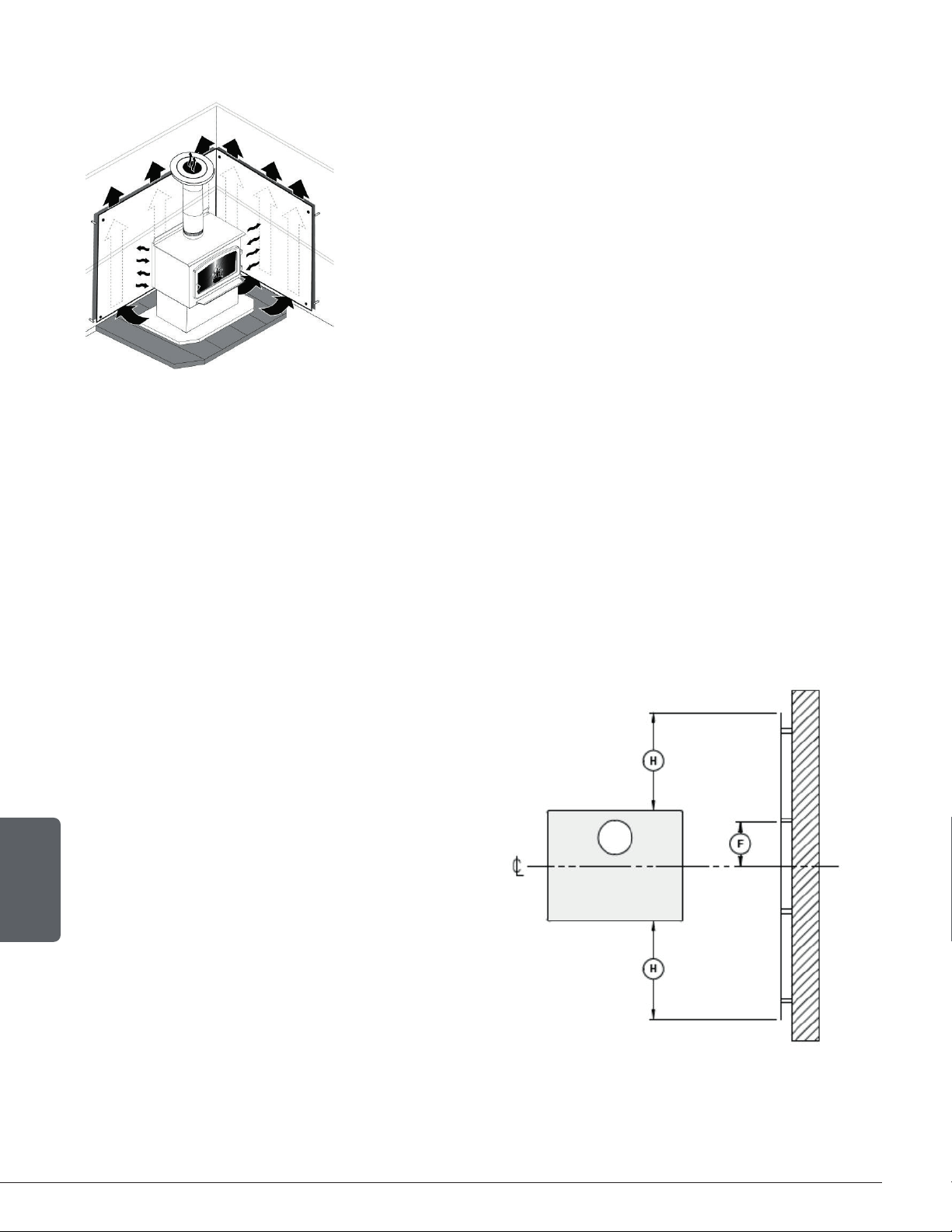
4. Floor Protection
This stove is designed to prevent the floor from overheating. However, it must be placed on a
non-flammable surface to protect the floor from hot embers that may fall during loading.
The floor protection must be a continuous, non combustible material, such as steel with a minimum
thickness of 0.015" (0.38 mm) or ceramic tiles sealed together with grout. Cement board, brick, or
any other approved or listed material suited for floor protection. No R factor required.
Any type of tile will require a continuous non combustible sheet beneath to prevent the possibility
of embers falling through to the combustible floor if cracks or separation should occur in the
finished surface. Check local codes for approved alternatives.
No protection is required if the unit is installed on a non-combustible floor (ex: concrete).
FLOOR PROTECTION
Canada USA
G
20
8" (203 mm) N/A
H 8" (203 mm) N/A
I 18" (457 mm)
From door
opening
16" (406 mm)
From door
opening
J N/A 8" (203 mm)
N
21
N/A See note 19
H
I
G
J
K
Figure 13: Floor Protection
U
T
S
84"
213 cm
Ve
Ho
N
20
The floor protection at the back of the stove is limited to the stove’s required clearance if such clearance is smaller than 8 inches (203 mm).
21
Only required under the horizontal section (Ho) of the connector. Must exceed each side of the connector by at least 2 inches (51 mm).
Page 20
Installation and Operation Manual - Wood Stove
ENGLISH
5. Reducing Wall and Ceiling Clearances Safely
It is often desired to use as little space as possible when installing
a wood stove. To do this, it is possible to reduce the clearances
safely and install the stove closer to the walls by permanently
installing a heat shield between the stove and the flammable
material.
The rules for heat shields are sometimes complicated. Read
and apply the instructions carefully. Some regions may have
different regulations. Consult the local building code or contact
the fire department for restrictions, inspection and installation
requirements in the area.
5.1 Shield Construction Rules
−
Adhesives used in shield construction must not ignite or lose adhesive qualities at temperatures
likely to be encountered.
− Mounting hardware which extends from the shield surface into combustibles may be used only
at the edges of the shield.
− Mounting hardware must allow full vertical ventilation.
A) Minimum clearance between the appliance
top and an unshielded combustible ceiling:
46 ½" (1181 mm)
B) Shield extension above the appliance: 20"
(500 mm)
C) Minimum space behind the shield: 1" (25 mm).
In Canada 7/8" (21 mm)
D) Clearance along the bottom of the shield:
minimum 1" (25 mm) and maximum 3" (75 mm)
E) Minimum clearance along the top of the
shield: 3" (75 mm)
F) Mounting hardware must not be located
closer than 8" (200 mm) from the vertical
centre line of the appliance.
G) Edge clearance for ceiling shields to side and
back walls: 3" (75 mm)
H) Shield extension beyond each side of the
appliance: 18" (450 mm)
Figure 14: Heat shield clearances
Page 21
Installation and Operation Manual - Wood Stove
ENGLISH
Figure 15: Heat shield clearances Figure 16: Heat shield clearances
H
H
Page 22
Installation and Operation Manual - Wood Stove
ENGLISH
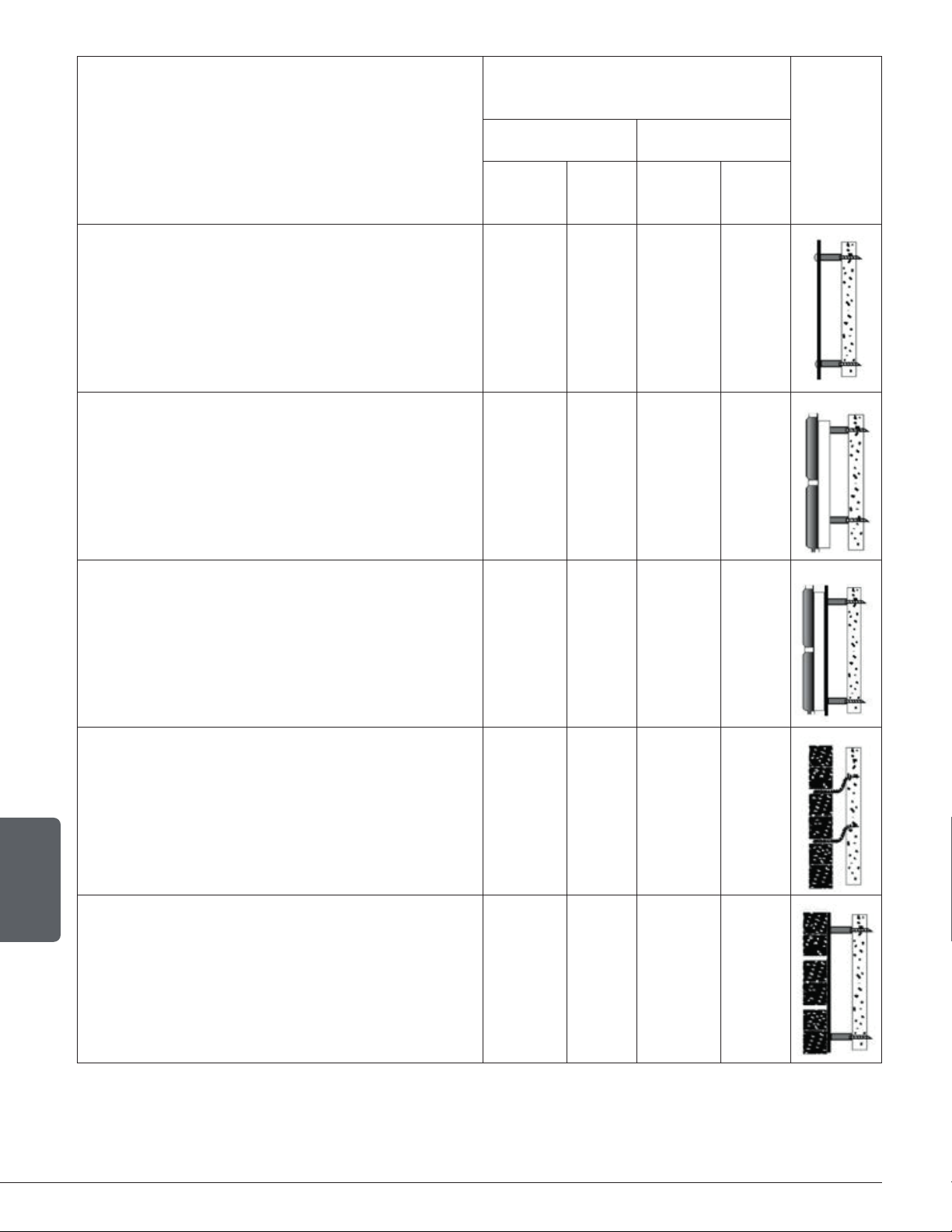
TYPE OF SHIELD
CLEARANCES MAY BE REDUCED BY
THESE PERCENTAGES
SIDES AND REAR TOP (CEILING)
CAN /
USA (%)
USA
MIN.
CAN /
USA (%)
USA
MIN.
Sheet metal, a minimum of 24 gauge (0.61 mm)
in thickness , spaced out at least 1" (25 mm)* by
non-combustible spacers
67
12"
(305 mm)
50
18"
(457 mm)
Ceramic tiles, or equivalent non-combustible
material, on non-combustible board spaced
out at least 1" (25 mm)* by non-combustible
spacers
50
18"
(457 mm)
33
24"
(610 mm)
Ceramic tiles, or equivalent non-combustible
material, on non-combustible board, with a
minimum of 24 gauge (0.61 mm) sheet metal
backing spaced out at least 1" (25 mm)* by
non-combustible spacers
67
12"
(305 mm)
50
24"
(610 mm)
Brick, spaced out at least 1" (25 mm)* by non-
combustible spacers
50
18"
(457 mm)
N/A N/A
Brick, with a minimum of 24 gauge (0.61 mm)
sheet metal backing, spaced out at least 1"
(25 mm)* by non-combustible spacers
67
12"
(305 mm)
N/A N/A
* In Canada this space can be ⅞" (21 mm)
Page 23
Installation and Operation Manual - Wood Stove
ENGLISH
6. INSTALLATION OF OPTIONS ON YOUR PRODUCT
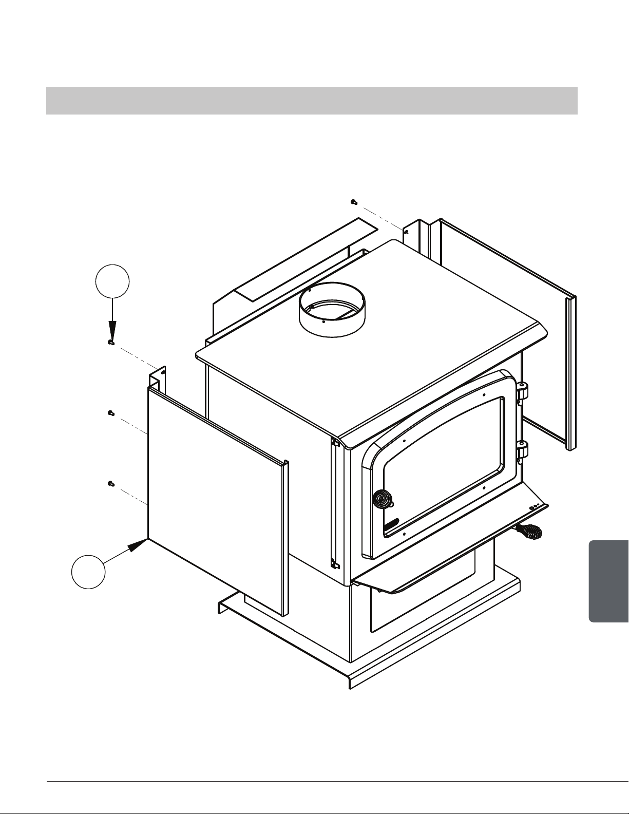
6.1 Decorative Panels
THE IMAGES SHOWN ARE FOR GUIDANCE ONLY AND MAY BE DIFFERENT FROM YOUR PRODUCT,
BUT THE ASSEMBLY REMAINS THE SAME.
To remove the decorative panel (A), remove the screws (B) and push forward on the panel to
unhook it from the bracket (E).
B
A
Page 24
Installation and Operation Manual - Wood Stove
ENGLISH
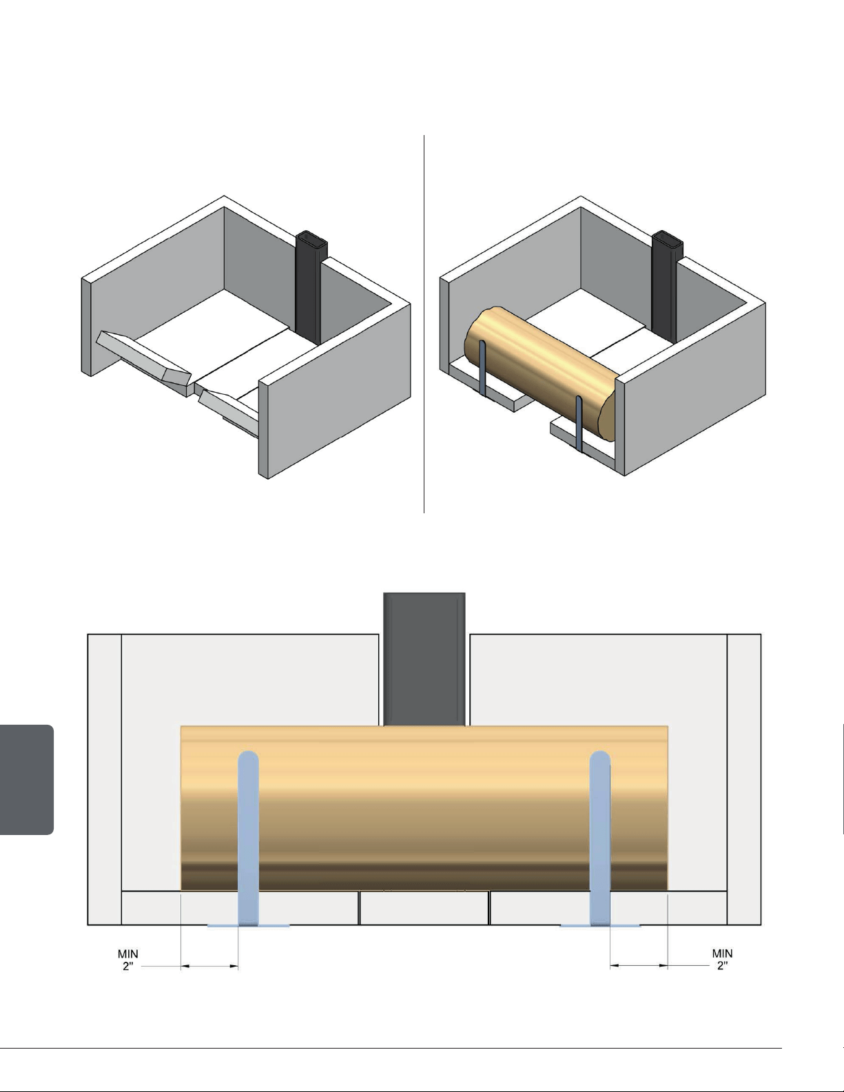
6.2 Log retainers installation
1. 2.
3.
Page 25
Installation and Operation Manual - Wood Stove
ENGLISH
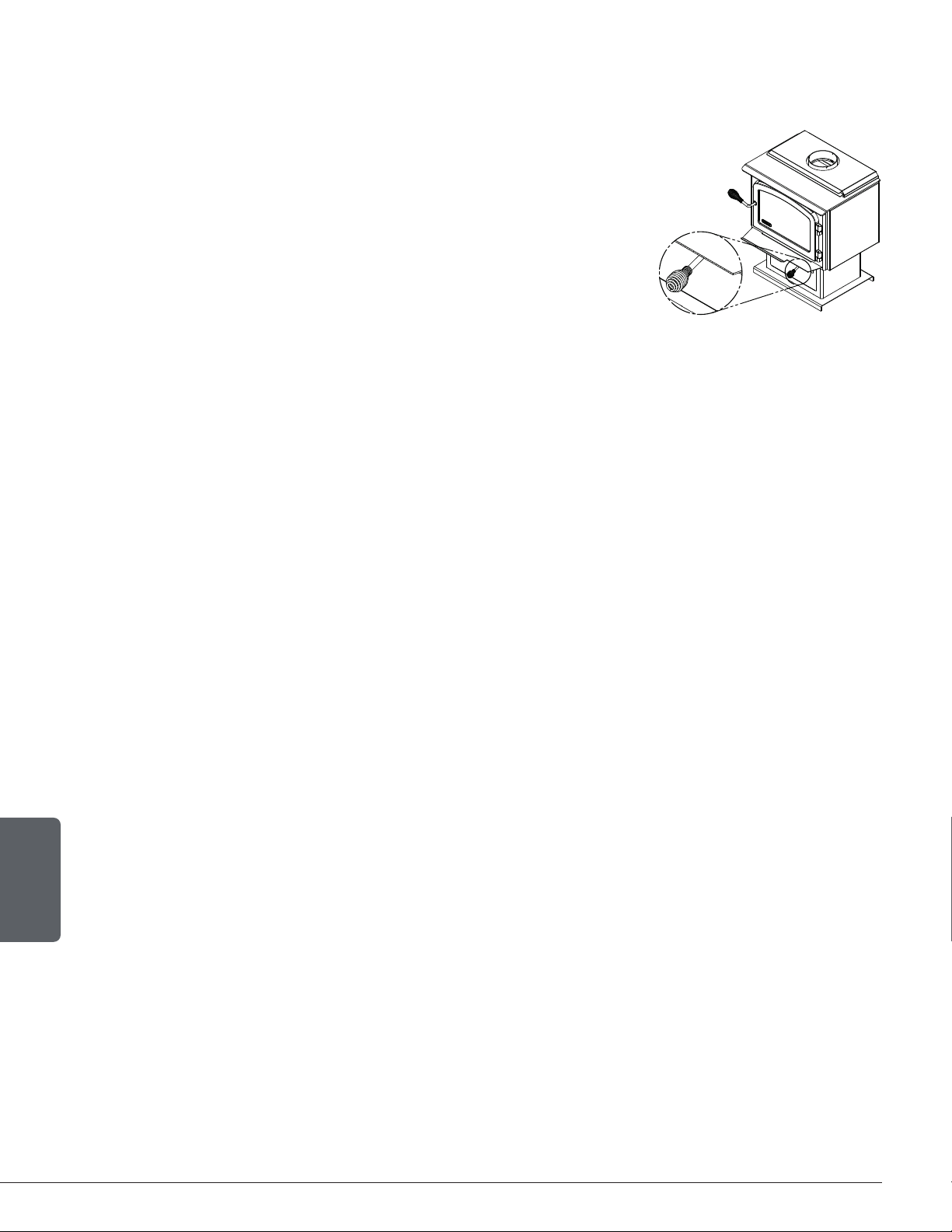
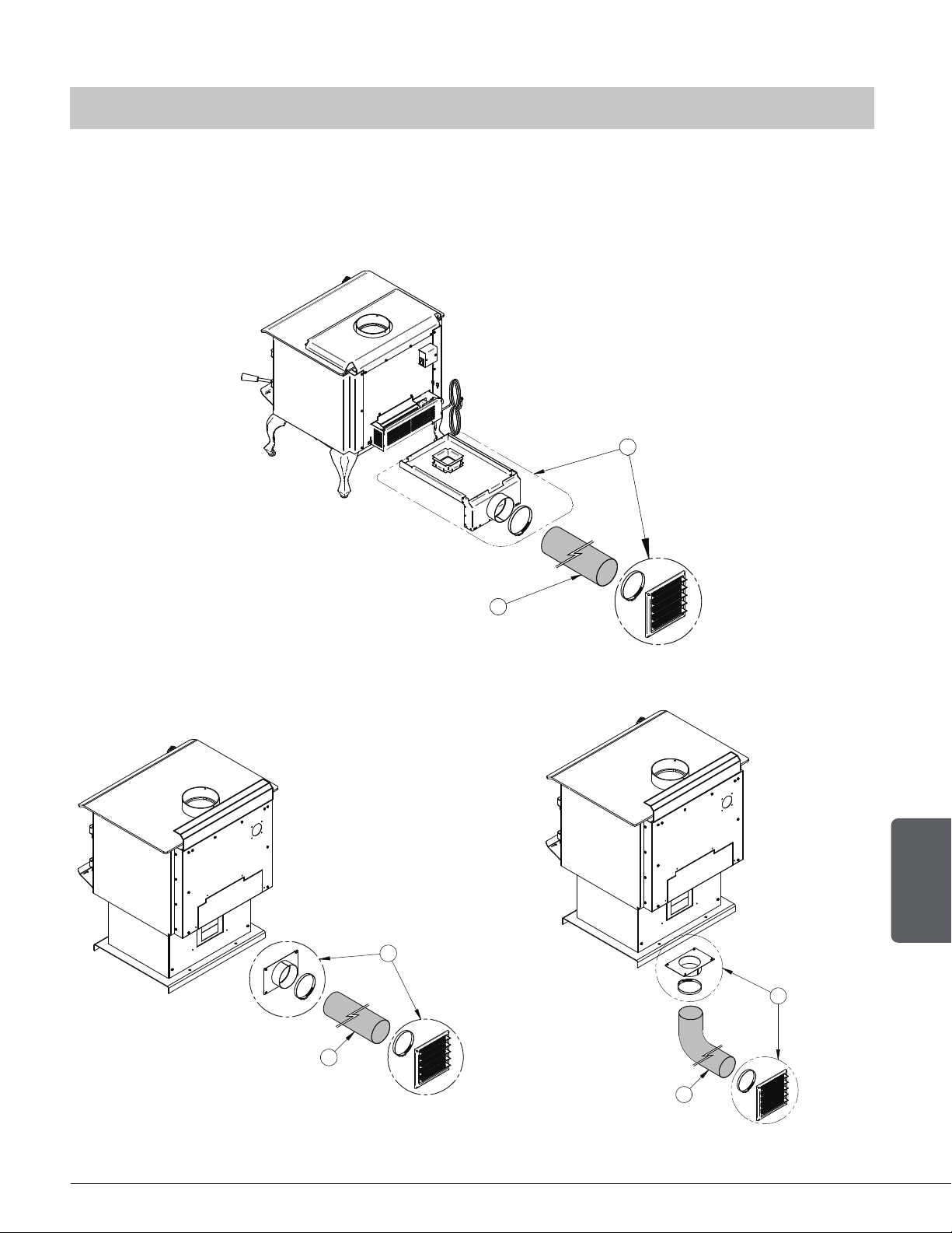
6.3 Optional Fresh Air Intake Kit Installation
THE IMAGES SHOWN ARE FOR GUIDANCE ONLY AND MAY BE DIFFERENT FROM YOUR PRODUCT,
BUT THE ASSEMBLY REMAINS THE SAME.
This mobile home approved stove requires the installation of a fresh air intake kit (A) and an
insulated fresh air intake pipe (HVAC type, must meet ULC S110 or UL 181 class 0 or class 1) (B),
sold separately. Refer to air intake kit installation instructions for more details.
Installation with legs
A
B
Installation with pedestal
A
B
A
B
Page 26
Installation and Operation Manual - Wood Stove
ENGLISH
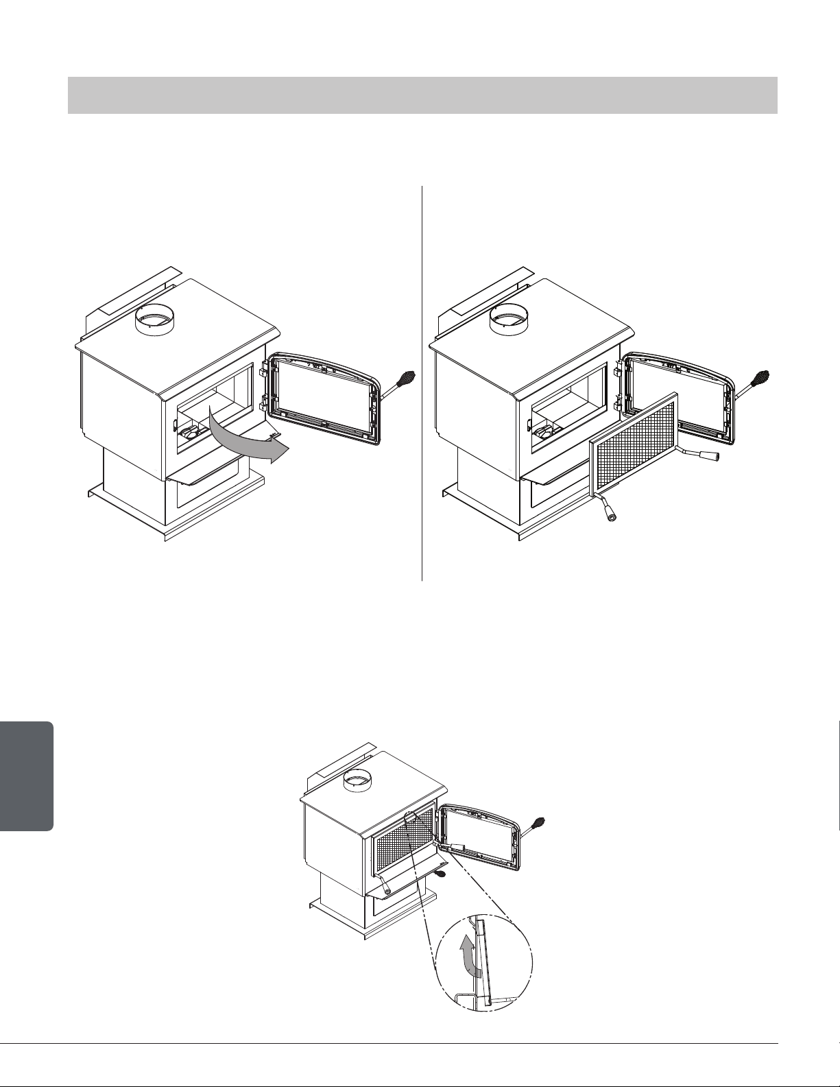
6.4 Optional Fire Screen Installation
THE IMAGES SHOWN ARE FOR GUIDANCE ONLY AND MAY BE DIFFERENT FROM YOUR PRODUCT,
BUT THE ASSEMBLY REMAINS THE SAME.
In the United States or in provinces with a particulate emission limit (eg. US EPA), the use of wood
stoves with the door open with a rigid rescreen is prohibited.
1. Open the door. 2. Hold the fire screen by the two handles and
bring it close to the door opening.
3. Lean the upper part of the fire screen against the top door opening making sure to stove the top
fire screen brackets behind the primary air deflector.
4. Lift the fire screen upwards and push the bottom part towards the stove then let the fire screen
rest on the bottom of the door opening.
Warning: Never leave the stove unattended while in use with the fire screen.
Page 27
Installation and Operation Manual - Wood Stove
ENGLISH
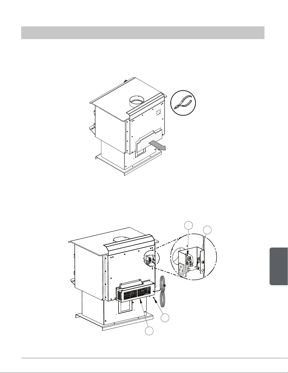
6.5 Optional Blower And Thermodisc Installation
THE IMAGES SHOWN ARE FOR GUIDANCE ONLY AND MAY BE DIFFERENT FROM YOUR PRODUCT,
BUT THE ASSEMBLY REMAINS THE SAME.
A blower and a thermodisc, sold separately, can be installed on the stove. The installation of the
blower is identical for a stove on legs or pedestal. Thermodisc allows the blower to operate only
when the stove is hot enough. See the instructions provided with the thermodisc for more details.
1. Remove the backplate by cutting the knockouts with pliers.
2. Screw the blower (D) in place using the screws (C) included in the installation manual. Screw
the thermodisc (A) with the screws (B) supplied with the thermodisc on the back of the stove.
Ensure that the blower’s power cord is not in contact with any surface of the stove to
prevent electrical shock or fire damage. Do not run the power cord beneath the stove.
A
B
C
D
Page 28
Installation and Operation Manual - Wood Stove
ENGLISH
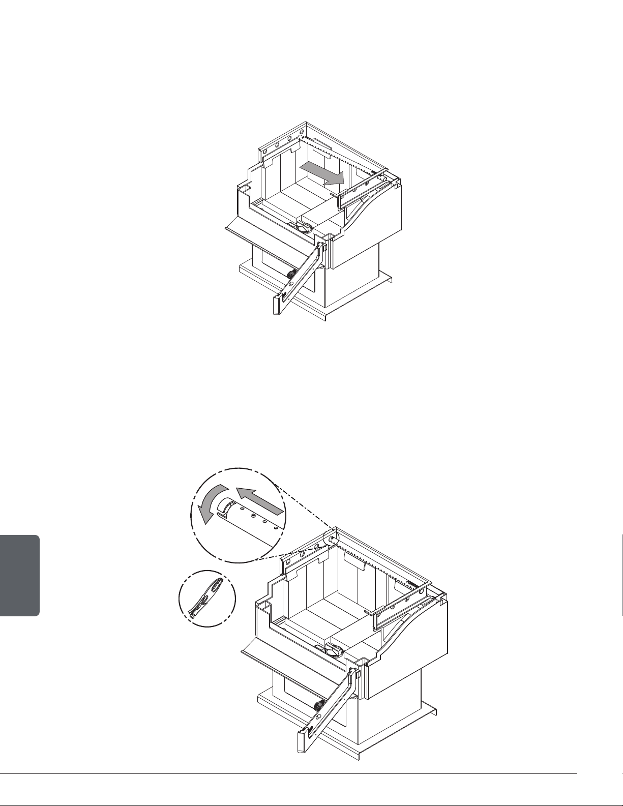
6.6 Air Tubes And Baffle Installation
1. Starting with the rear tube, lean and insert the right end of the secondary air tube into the rear
right channel hole. Then lift and insert the left end of the tube into the rear left channel.
2. Align the notch in the left end of the tube with the key of the left air channel hole. Using a « Wise grip »
hold the tube and lock it in place by turning the tube as shown. Make sure the notch reaches
the end of the key way.
3. Put the baffle in place.
4. Repeat steps 1 and 2 for the three other tubes.
5. To remove the tubes use the above steps in reverse order.
Page 29
Installation and Operation Manual - Wood Stove
ENGLISH
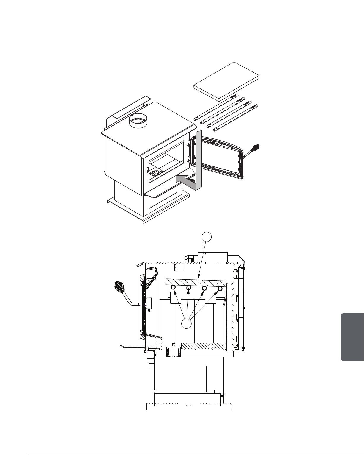
Note that secondary air tubes (B) can be replaced without removing the baffle board (A) and that
all tubes are identical.
A
B
Page 30
Installation and Operation Manual - Wood Stove
ENGLISH
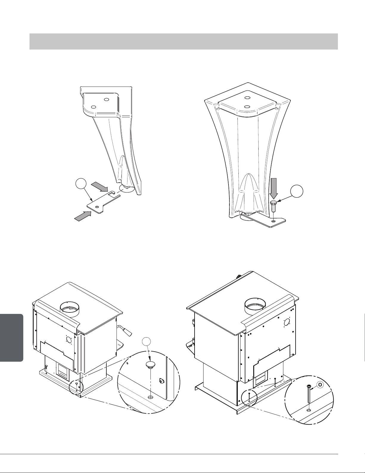
6.7 Mobile Home Installation
THE IMAGES SHOWN ARE FOR GUIDANCE ONLY AND MAY BE DIFFERENT FROM YOUR PRODUCT,
BUT THE ASSEMBLY REMAINS THE SAME.
1. For a stove on legs, install a plate (L) on each leg and screw it in place with the proper hardware (M).
L
4x
M
4x
2. For a stove on a pedestal, remove the plugs (N) and screw the base on the floor with the proper
hardware (O).
N
Page 31
Installation and Operation Manual - Wood Stove
ENGLISH
7. Maintenance/Parts Replacement
Do not clean the glass when the stove is hot.
Do not abuse the glass door by striking or slamming shut.
Do not use the stove if the glass is broken.
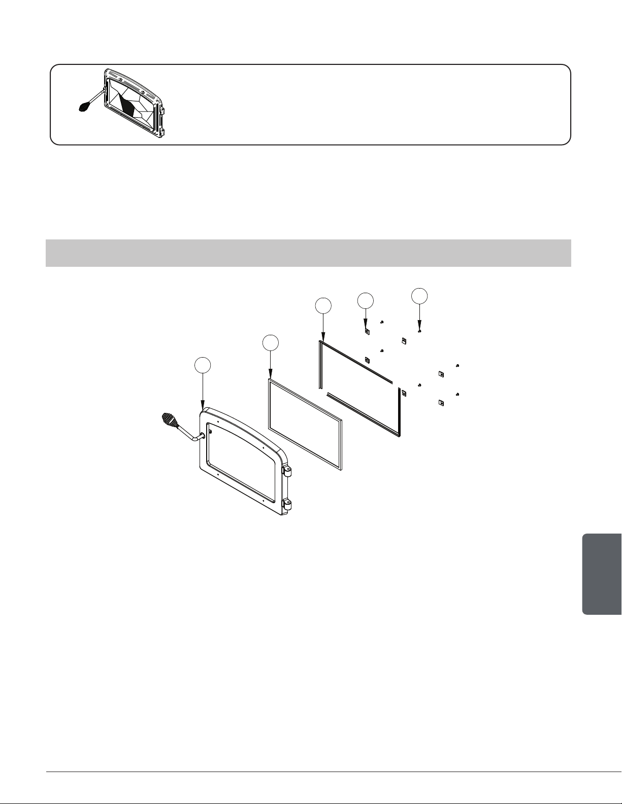
7.1 Replacement
The glass used is a ceramic glass, 5/32" (4 mm) thick, 15 ⅞" x 9 ⅞" (403 mm x 251 mm), tested
to reach temperatures up to 1400º F. If the glass breaks, it must be replaced with one having
the same specification.
THE IMAGES SHOWN ARE FOR GUIDANCE ONLY AND MAY BE DIFFERENT FROM YOUR PRODUCT,
BUT THE ASSEMBLY REMAINS THE SAME.
B
A
C
D
E
1. Remove the door (E) from its hinges and lay it on a soft, flat surface.
2. Remove the six screws (A), the six glass retainers (B), and the metal frames (C).
3. Remove the glass (D). If it is damaged install a new one in place. The replacement glass must
have a gasket all around (see procedure below).
4. Reinstall the glass, being careful to centre the glass in the door and not to over-tightening the
retaining screw.
The two main causes of broken door glass are uneven placement in the door and over-tightening
the retaining screws.
Page 32
Installation and Operation Manual - Wood Stove
ENGLISH
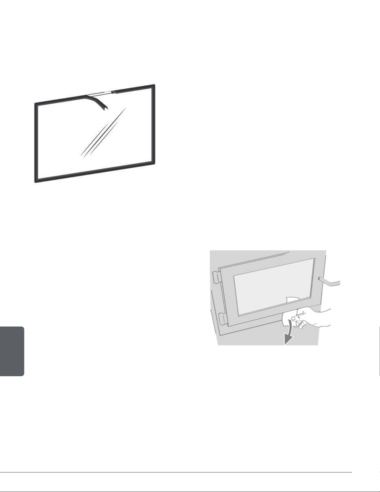
7.2 Gasket
The glass gasket is flat, adhesive-backed, woven fibreglass. The gasket must be centred on the
edge of the glass.
1. Follow the steps of the previous section to remove the
glass.
2. Remove the old gasket and clean the glass thoroughly.
3. Peel back a section of the paper covering the adhesive
and place the gasket on a table with the adhesive side
up.
4. Stick the end of the gasket to the middle of one edge,
then press the edge of the glass down onto the gasket,
taking care that it is perfectly centred on the gasket.
5. Peel off more of the backing and rotate the glass. The
gasket must not be stretched during installation.
6. Cut the gasket to the required length.
7. Pinch the gasket onto the glass in a U shape, all around
the glass.
7.3 Door
In order for the stove to burn at its best
efficiency, the door must provide a perfect
seal with the firebox. The tightness of the
door seal can be verified by closing and
latching the door on a strip of paper. The
test must be performed all around the door.
If the paper slips out easily anywhere, either
adjust the door or replace the gasket.
Page 33
Installation and Operation Manual - Wood Stove
ENGLISH
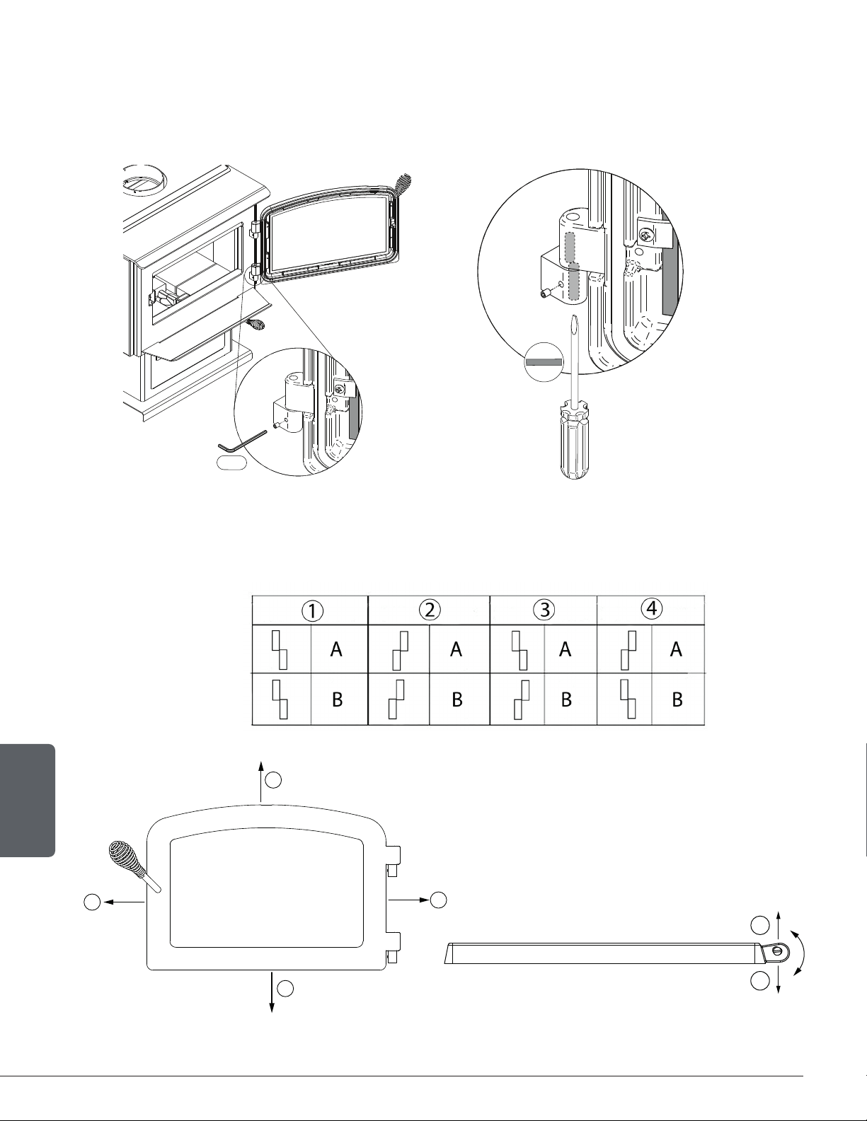
7.3.1 Adjustment
In order for the stove to burn at its best efficiency, the door must provide a perfect seal with the
firebox. Therefore, the gasket should be inspected periodically to check for a good seal. The
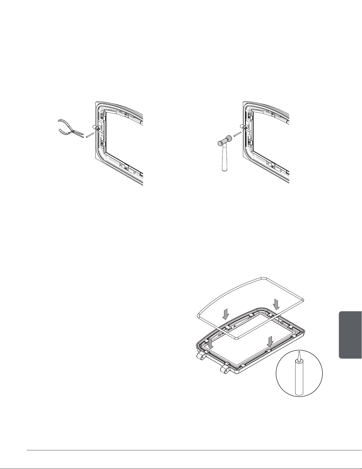
gasket seal may be improved with a simple latch mechanism adjustment:
1. Remove the split pin by pulling and turning it using pliers.
2. Turn the handle one counterclockwise turn to increase pressure.
3. Reinstall the split pin with a small hammer.
Figure 17: Removing the split pin Figure 18: Installing the split pin
7.3.2 Gasket
It is important to replace the gasket with another having the same diameter and density to
maintain a good seal.
1. Remove the door and place it face-down on
something soft like a cushion of rags or a piece
of carpet.
2. Remove the old gasket from the door. Use a
screwdriver to scrape the old gasket adhesive
from the door gasket groove.
3. Apply a bead of approximately 3/16" (5 mm)
of high temperature silicone in the door gasket
groove. Starting from the middle, hinges side,
press the gasket into the groove. The gasket
must not be stretched during installation.
4. Leave about ½" long of the gasket when cutting
and press the end into the groove. Tuck any loose
fibers under the gasket and into the silicone.
5. Close the door. Do not use the stove for 24 hours.
Page 34
Installation and Operation Manual - Wood Stove
ENGLISH
7.4 Door alignment
T
o align, open the door and loosen the pressures screws located on the lower and upper hinges of the
door using a 3/32” Allen key to free the
adjustable hinge rods.
3/32"
Using a flat screwdriver, turn the adjustable hinge rods in the direction shown to adjust the doors. Tighten
all door hinge pressure screws when they are at the desired positions. Configurations 1-2-3-4-5-6, show
in which direction these act on the adjustment of the door
4
2
A
B
1
3
5
6
Page 35
Installation and Operation Manual - Wood Stove
ENGLISH
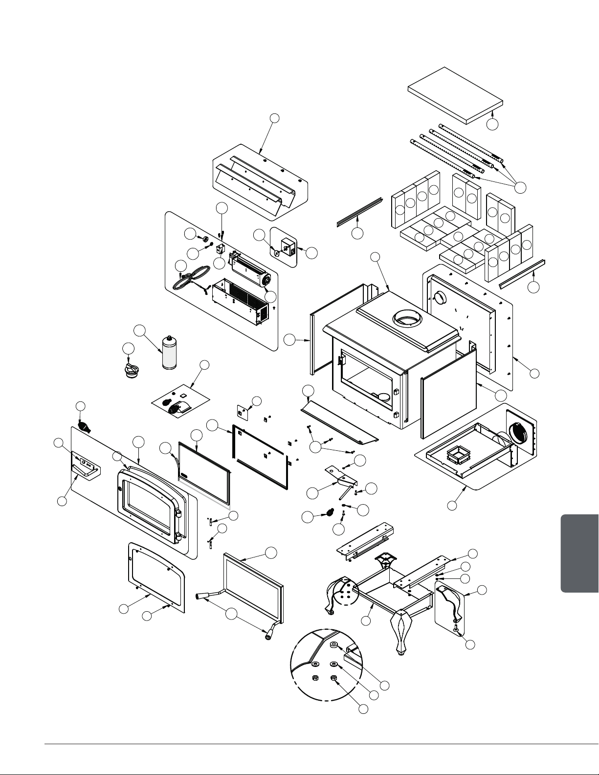
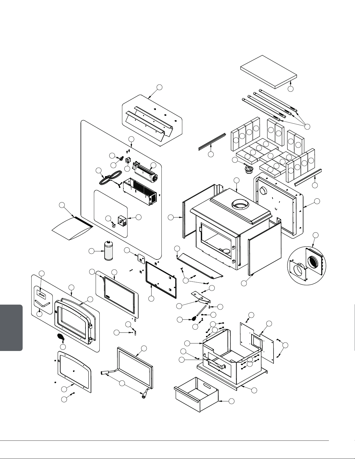
8. Exploded Diagram and Parts List - with Legs
7
11
8
12
15
14
50
51
48
36
37
41
40
39
42
43
44
45
31
31
20
17
18
17
16
33
34
34
34
33
34
34
34
35
33
34
34
34
33
34
34
34
35
34
34
35
19
29
47
29
46
24
25
2
1
10
9
6
3
21
DETAIL C
22
23
23
22
27
26
32
49
13
5
4
38
30
28
C
Page 36
Installation and Operation Manual - Wood Stove
ENGLISH
IMPORTANT: THIS IS DATED INFORMATION. When requesting service or replacement parts
for your unit, please provide the model number and the serial number. We reserve the right to
change parts due to technology upgrades or availability. Contact an authorized dealer to obtain
any of these parts. Never use substitute materials. Use of non-approved parts can result in poor
performance and safety hazards.
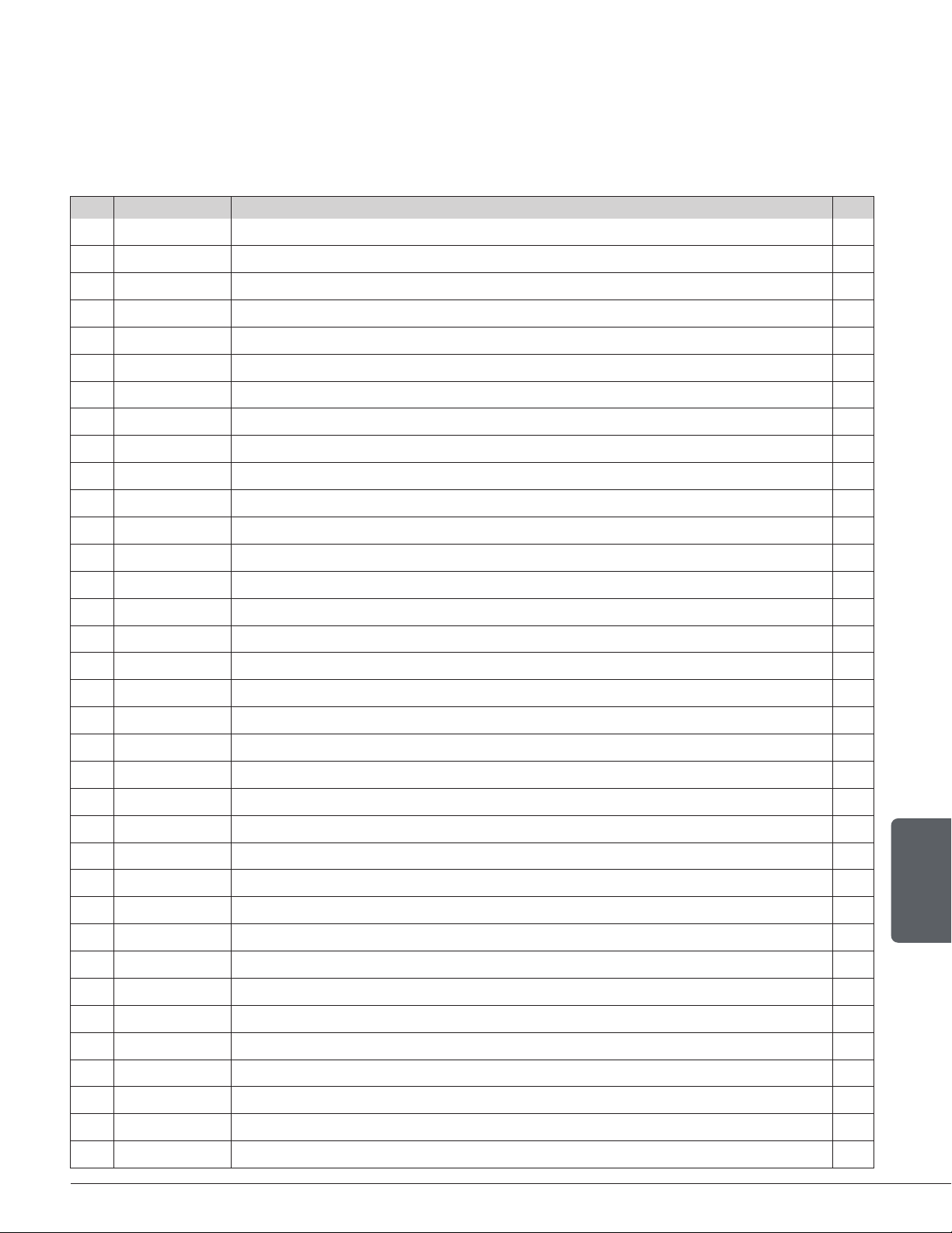
# Item Description Qty
1 PL65726 BRUSHED NICKEL OVERLAY 1
2 30253 MECHANICAL SCREW 1/4-20 X 5/16" BUTTONHEAD HEX DEEP #5/32 SS 18-8 4
3 AC07868 1/2" COIL HANDLE 1
4 AC09185 DOOR LATCH KIT 1
5 SE70697 REPLACEMENT HANDLE WITH LATCH KIT 1
6 AC06500 SILICONE AND 5/8" X 8' BLACK DOOR GASKET KIT 1
7 SE24107-10 CAST IRON DOOR WITH GASKET AND HANDLE 1
7 SE24107-08 DOOR ASSEMBLY 1
8 AC06400 3/4" X 6' FLAT BLACK SELF-ADHESIVE GLASS GASKET 1
9 30117 SOCKET SET SCREW #10-32 X 1/4" 2
10 30579 ADJUSTABLE HINGE PIN 3/8"Ø - 5/16" X 1 63/64"L 2
11 SE55103 GLASS WITH GASKET - 17 1/8"W X 10 3/16"H 1
12 PL55041 GLASS RETAINER FRAME 2
13 SE53585 GLASS RETAINER KIT WITH SCREWS (12 PER KIT) 1
14 PL74079 ASH SHELF 1
15 30507 BLACK TORX SCREW WITH FLAT HEAD TYPE F 1/4-20 X 3/4" 3
16 30187 STAINLESS WASHER ID 17/64" X OD 1/2" 1
17 30506 SCREW PAN TORX TYPE F 1/4-20 X 1" BLACK 2
18 30206 ZINC WASHER 5/16"ID X 3/4"OD 1
19 SE65305 AIR CONTROL DAMPER ASS. 1
20 AC07869 3/8" COIL HANDLE 1
21 PL74095 LEFT OR RIGHT LEG SUPPORT 2
22 30185 17/64" AA TYPE WASHER BLACK 8
23 30100 BLACK HEX NUT 1/4 - 20 8
24 PL24098 BLACK CAST IRON LEG WITH LEVELING BLOT 4
25 30050 LEVELING BOLT 3/8-16 X 1 1/2" 4
26 SE53596 ASH DRAWER 1
27 30193 FLAT WASHER .281" ID X .625" OD X .188" BLACK OXIDE 8
28 AC01211 5"Ø FRESH AIR INTAKE KIT FOR WOOD STOVE ON LEGS 1
29 PL74106 LEFT OR RIGHT DECORATIVE PANEL 2
30 SE65353 BACK HEAT SHIELD ASSEMBLY 1
31 PL65127 FLOORED BRICK RETAINER 2
32 SE74082 AIR MATE 1
33 29007 3 1/4" X 9" X 1 1/4" REFRACTORY BRICK 4
34 29015 4" X 9" X 1 1/4" REFRACTORY BRICK 14
Page 37
Installation and Operation Manual - Wood Stove
ENGLISH
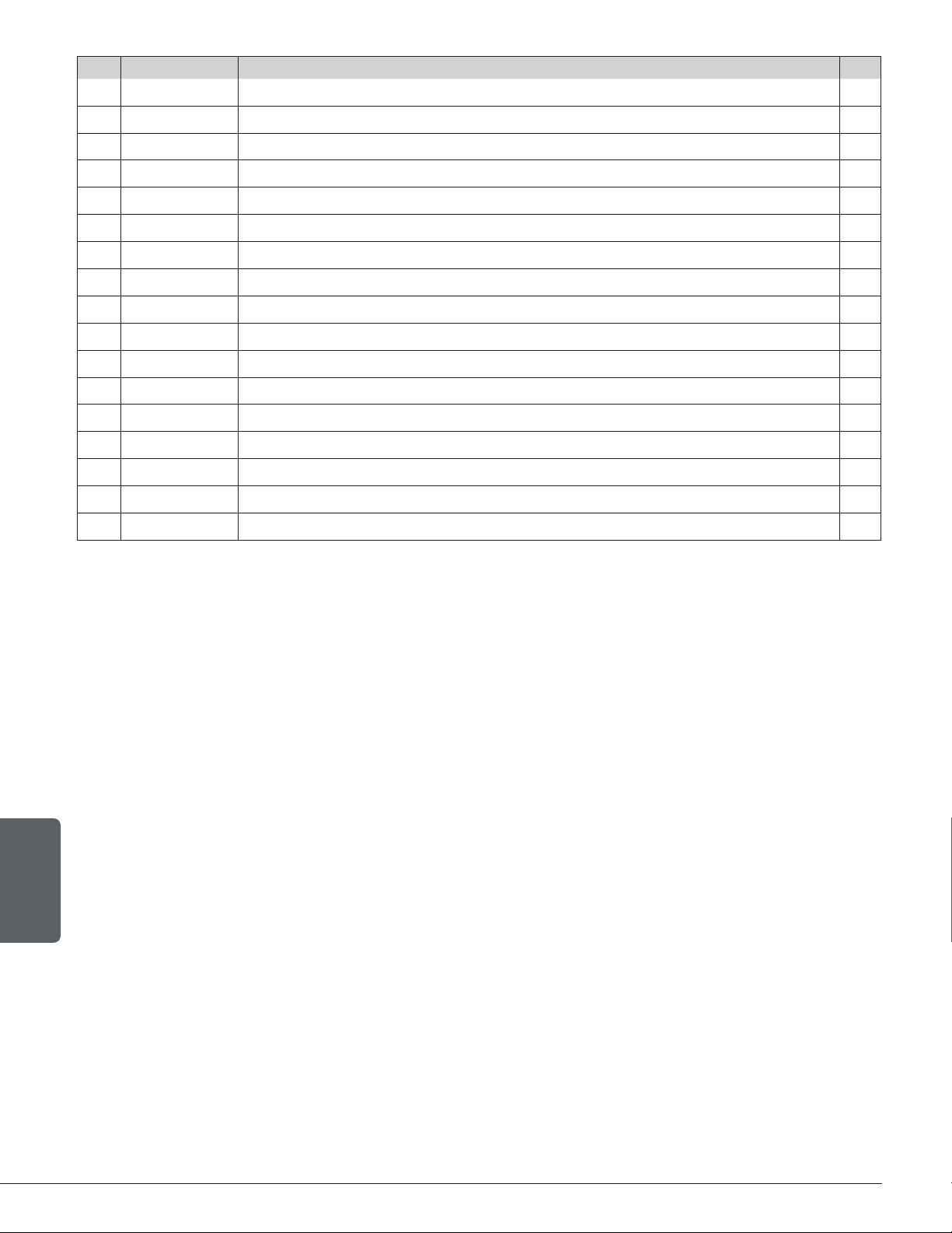
# Item Description Qty
35 29010 4 1/2" X 9" X 1 1/4" REFRACTORY BRICK 3
36 PL65514 SECONDARY AIR TUBE 4
37 21388 VERMICULITE BAFFLE 20" X 12 1/2" X 1 1/4" 1
38 SE65505 TOP AIR DEFLECTOR PROTECTOR KIT 1
39 AC02055 QUICK CONNECT THERMODISC 1
40 44028 CERAMIC THERMODISC F110-20F 1
41 AC03095 BLOWER WITH VARIABLE SPEED CONTROL (UP TO 130 CFM) 1
42 44085 RHEOSTAT KNOB 1
43 44087 RHEOSTAT NUT 1
44 44080 RHEOSTAT WITHOUT NUT (MODEL KBMS-13BV) 1
45 44070 CROSSFLOW BLOWER SINGLE CAGE 130 CFM 115V-60Hz-56W 1
46 60013 POWER CORD 96" X 18-3 type SJT (50 pcs per carton) 1
47 AC05959 METALLIC BLACK STOVE PAINT - 342 g (12oz) AEROSOL 1
48 24096 ROUND CAST IRON ASH PLUG 1
49 SE46240 MANUAL KIT ESCAPE 1800 1
50 AC01315 RIGID FIRESCREEN 1
51 30898 ROUND WOODEN BLACK HANDLE 2
Page 38
Installation and Operation Manual - Wood Stove
ENGLISH
9. Exploded Diagram and Parts List - with Pedestal
3
6
11
10
15
14
51
33
37
38
40
46
47
41
42
43
44
32
32
20
18
19
18
16
34
35
35
35
34
35
35
35
36
34
35
35
35
34
35
35
35
36
35
35
36
17
29
49
29
45
1
2
50
24
27
8
9
23
2
1
28
4
12
25
24
30
7
24
2
1
2
2
26
5
13
39
48
31
22
52
Page 39
Installation and Operation Manual - Wood Stove
ENGLISH
IMPORTANT: THIS IS DATED INFORMATION. When requesting service or replacement parts
for your unit, please provide the model number and the serial number. We reserve the right to
change parts due to technology upgrades or availability. Contact an authorized dealer to obtain
any of these parts. Never use substitute materials. Use of non-approved parts can result in poor
performance and safety hazards.
# Item Description Qty
1 PL65726 BRUSHED NICKEL OVERLAY 1
2 30253 MECHANICAL SCREW 1/4-20 X 5/16" BUTTONHEAD HEX DEEP #5/32 SS 18-8 4
3 AC07868 1/2" COIL HANDLE 1
4 SE70697 REPLACEMENT HANDLE WITH LATCH KIT 1
5 AC09185 DOOR LATCH KIT 1
6 SE24107-08 DOOR ASSEMBLY 1
6 SE24107-10 CAST IRON DOOR WITH GASKET AND HANDLE 1
7 AC06500 SILICONE AND 5/8" X 8' BLACK DOOR GASKET KIT 1
8 30117 SOCKET SET SCREW #10-32 X 1/4" 2
9 30579 ADJUSTABLE HINGE PIN 3/8"Ø - 5/16" X 1 63/64" L 2
10 AC06400 3/4" X 6' FLAT BLACK SELF-ADHESIVE GLASS GASKET 1
11 SE55103 GLASS WITH GASKET - 17 1/8"W X 10 3/16"H 1
13 SE53585 GLASS RETAINER KIT WITH SCREWS (12 PER KIT) 1
14 PL74079 ASH SHELF 1
15 30507 BLACK TORX SCREW WITH FLAT HEAD TYPE F 1/4-20 X 3/4" 3
16 30187 STAINLESS WASHER ID 17/64" X OD 1/2" 1
17 SE65305 AIR CONTROL DAMPER ASS. 1
18 30506 SCREW PAN TORX TYPE F 1/4-20 X 1" BLACK 2
19 30206 ZINC WASHER 5/16"ID X 3/4"OD 1
20 AC07869 3/8" COIL HANDLE 1
21 30185 17/64" AA TYPE WASHER BLACK 4
22 30100 BLACK HEX NUT 1/4 - 20 4
23 PL74075 BASE 1
24 30154 BLACK SCREW #10 X 5/8" QUADREX #2 TYPE A 6
25 PL74085 DÉCORATIVE DASH 1
26 PL74084 SOCLE 1
27 PL65542 BASE COVER 1
28 PL65960 ASH PAN 1
29 PL74106 LEFT OR RIGHT DECORATIVE PANEL 2
30 AC01336 5"Ø FRESH AIR INTAKE KIT FOR WOOD STOVE ON PEDESTAL 1
31 SE65353 BACK HEAT SHIELD ASSEMBLY 1
32 PL65127 FLOORED BRICK RETAINER 2
33 24096 ROUND CAST IRON ASH PLUG 1
34 29007 3 1/4" X 9" X 1 1/4" REFRACTORY BRICK 4
35 29015 4" X 9" X 1 1/4" REFRACTORY BRICK 14
Page 40
Installation and Operation Manual - Wood Stove
ENGLISH
# Item Description Qty
36 29010 4 1/2" X 9" X 1 1/4" REFRACTORY BRICK 3
37 PL65514 SECONDARY AIR TUBE 4
38 21388 VERMICULITE BAFFLE 20" X 12 1/2" X 1 1/4" 1
39 SE65505 TOP AIR DEFLECTOR PROTECTOR KIT 1
40 AC03095 BLOWER WITH VARIABLE SPEED CONTROL (UP TO 130 CFM) 1
41 44085 RHEOSTAT KNOB 1
42 44087 RHEOSTAT NUT 1
43 44080 RHEOSTAT WITHOUT NUT (MODEL KBMS-13BV) 1
44 44070 CROSSFLOW BLOWER SINGLE CAGE 130 CFM 115V-60Hz-56W 1
45 60013 POWER CORD 96" X 18-3 type SJT (50 pcs per carton) 1
46 44028 CERAMIC THERMODISC F110-20F 1
47 AC02055 QUICK CONNECT THERMODISC 1
48 SE46240 ESCAPE 1800 MANUAL KIT 1
49 AC05959
METALLIC BLACK STOVE PAINT - 342 g (12oz) AEROSOL
1
50 AC01315 RIGID FIRESCREEN 1
51 30898 ROUND WOODEN BLACK HANDLE 2
52 SE74082 AIR MATE 1
Page 41
Installation and Operation Manual - Wood Stove
ENGLISH
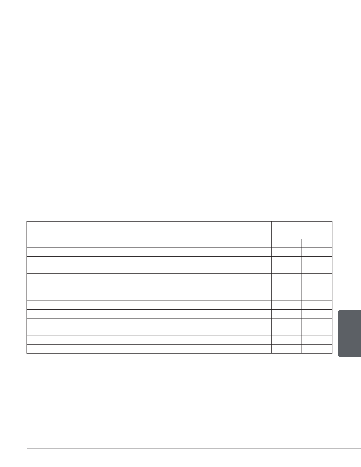
DROLET LIMITED LIFETIME WARRANTY
The warranty of the manufacturer extends only to the original retail purchaser and is not transferable. This
warranty covers brand new products only, which have not been altered, modified nor repaired since shipment
from the factory. Proof of purchase (dated bill of sale), model name and serial number must be supplied when
making any warranty claim to the DROLET dealer.
This warranty applies to normal residential use only. This warranty is void if the unit is used to burn material other
than cordwood (for which the unit is not certied by EPA) and void if not operated according to the owner's manual.
Damages caused by misuse, abuse, improper installation, lack of maintenance, over ring, negligence or accident
during transportation, power failures, downdrafts, venting problems or underestimated heating area are not covered
by this warranty. The recommended heated area for a given appliance is dened by the manufacturer as its capacity
to maintain a minimum acceptable temperature in the designated area in case of a power failure.
This warranty does not cover any scratch, corrosion, distortion, or discoloration. Any defect or damage caused
by the use of unauthorized or other than the original parts voids this warranty. An authorized qualified technician
must perform the installation in accordance with the instructions supplied with this product and all local and
national building codes. Any service call related to an improper installation is not covered by this warranty.
The manufacturer may require that defective products be returned or that digital pictures be provided to support
the claim. Returned products are to be shipped prepaid to the manufacturer for investigation. Transportation
fees to ship the product back to the purchaser will be paid by the manufacturer. Repair work covered by the
warranty, executed at the purchaser’s domicile by an authorized qualified technician requires the prior approval
of the manufacturer. All parts and labour costs covered by this warranty are limited according to the table below.
The manufacturer, at its discretion, may decide to repair or replace any part or unit after inspection and
investigation of the defect. The manufacturer may, at its discretion, fully discharge all obligations with respect to
this warranty by refunding the wholesale price of any warranted but defective parts. The manufacturer shall, in
no event, be responsible for any uncommon, indirect, consequential damages of any nature, which are in excess
of the original purchase price of the product. A one-time replacement limit applies to all parts benefiting from
lifetime coverage. This warranty applies to products purchased after March 1
st
2019.
DESCRIPTION
WARRANTY
APPLICATION*
PARTS LABOUR
Combustion chamber (welds only) and cast iron door frame. Lifetime 3 years
Surrounds, heat shields, ash drawer, steel legs, pedestal, trims (aluminum extrusions),
plating (defective manufacture**), and convector air-mate.
5 years 3 years
Removable stainless steel combustion chamber components, secondary air tubes**,
deflectors, and supports.
5 years N/A
Glass retainers, handle assembly, and air control mechanism. 3 years 1 year
Carbon steel combustion chamber components, vermiculite baffle**, and C-Cast baffle**. 2 years N/A
Standard blower, heat sensors, switches, rheostat, wiring, and other controls. 1 year 1 year
Optional blower, paint (peeling**), ceramic glass (thermal breakage only**), ceramic fibre
blankets, gaskets, insulation, and other options.
1 year N/A
Firebricks. N/A N/A
All parts replaced under the warranty. 90 days N/A
*Subject to limitations above. **Picture required.
Labour cost and repair work to the account of the manufacturer are based on a predetermined rate schedule
and must not exceed the wholesale price of the replacement parts. Shall your unit or a component be defective,
contact immediately your DROLET dealer. To accelerate processing of your warranty claim, make sure to have
on hand the following information when calling:
• Your name, address and telephone number;
• Bill of sale and dealer’s name;
• Installation configuration;
•
Serial number and model name as indicated on the
nameplate fixed to the back of your unit;
• Nature of the defect and any relevant information.
Before shipping your unit or defective component to our plant, you must obtain an Authorization
Number from your DROLET dealer. Any merchandise shipped to our plant without authorization will
be refused automatically and returned to the sender.

NOTES :

NOTES :

Stove Builder International inc.
250, rue de Copenhague,
St-Augustin-de-Desmaures (Québec) Canada
G3A 2H3
418-908-8002
www.sbi-international.com
This document is available for free download on the
manufacturer’s website. It is a copyrighted document.
Resale is strictly prohibited. The manufacturer may update
this document from time to time and cannot be responsible
for problems, injuries, or damages arising out of the use
of information contained in any document obtained from
unauthorized sources.