D ONE
1-Kanal Class D Verstärker
1-channel Class D amplier
deutsch / english

Sehr geehrter Kunde,
Wir gratulieren Ihnen zum Kauf dieses hochwer-
tigen HELIX Verstärkers.
Audiotec Fischer setzt mit der HELIX D ONE neue
Maßstäbe in puncto Preis-Leistungsverhältnis.
Dabei protieren Sie als Kunde direkt von unserer
mehr als 30-jährigen Erfahrung in der Forschung
und Entwicklung von Audiokomponenten.
Dieser Verstärker wurde von uns nach neuesten
technischen Erkenntnissen entwickelt und zeichnet
sich durch hervorragende Verarbeitung und eine
überzeugende Anwendung ausgereifter Technolo-
gien aus.
Viel Freude an diesem Produkt wünscht Ihnen das
Team von
AUDIOTEC FISCHER
Allgemeines zum Einbau von HELIX-Kompo-
nenten
Um alle Möglichkeiten des Produktes optimal aus-
schöpfen zu können, lesen Sie bitte sorgfältig die
nachfolgenden Installationshinweise. Wir garantie-
ren, dass jedes Gerät vor Versand auf seinen ein-
wandfreien Zustand überprüft wurde.
Vor Beginn der Installation unterbrechen Sie
den Minusanschluss der Autobatterie.
Wir empfehlen Ihnen, die Installation von einem
Einbauspezialisten vornehmen zu lassen, da der
Nachweis eines fachgerechten Einbaus und An-
schlusses des Gerätes Voraussetzung für die Ga-
rantieleistungen sind.
Installieren Sie Ihren Verstärker an einer trocke-
nen Stelle im Auto und vergewissern Sie sich, dass
der Verstärker am Montageort genügend Kühlung
erhält. Montieren Sie das Gerät nicht in zu kleine,
abgeschlossene Gehäuse ohne Luftzirkulation
oder in der Nähe von wärmeabstrahlenden Teilen
oder elektronischen Steuerungen des Fahrzeuges.
Im Sinne der Unfallsicherheit muss der Verstärker
professionell befestigt werden. Dieses geschieht
über Schrauben, die in eine Montageäche ein-
geschraubt werden, die wiederum genügend Halt
bieten muss.
Bevor Sie die Schrauben im Montagefeld befesti-
gen, vergewissern Sie sich, dass keine elektrischen
Kabel und Komponenten, hydraulische Bremslei-
tungen, der Benzintank etc. dahinter verborgen
sind. Diese könnten sonst beschädigt werden. Ach-
ten Sie bitte darauf, dass sich solche Teile auch in
der doppelten Wandverkleidung verbergen können.
Allgemeines zum Anschluss des D ONE Ver-
stärkers
Der Verstärker darf nur in Kraftfahrzeuge eingebaut
werden, die den 12 V-Minuspol an Masse haben.
Bei anderen Systemen können der HELIX Verstär-
ker und die elektrische Anlage des Kfz beschädigt
werden. Die Plusleitung für die gesamte Anlage
sollte in einem Abstand von max. 30 cm von der
Batterie mit einer Hauptsicherung abgesichert wer-
den. Der Wert der Sicherung errechnet sich aus der
maximalen Stromaufnahme der Car-Hi Anlage.
Verwenden Sie zum Anschluss des Verstärkers
an die Stromversorgung des Fahrzeugs aus-
schließlich geeignete Kabel mit ausreichen-
dem Kabelquerschnitt. Die Sicherungen im
Verstärker dürfen nur mit den gleichen Werten
(2 x 30 A) ersetzt werden, um eine Beschädi-
gung des Gerätes zu verhindern. Höhere Werte
können zu gefährlichen Folgeschäden führen!
Die Kabelverbindungen müssen so verlegt sein,
dass keine Klemm-, Quetsch- oder Bruchgefahr be-
steht. Bei scharfen Kanten (Blechdurchführungen)
müssen alle Kabel gegen Durchscheuern gepols-
tert sein. Ferner darf das Versorgungskabel niemals
mit Zuleitungen zu Vorrichtungen des Kfz (Lüfter-
motoren, Brandkontrollmodulen, Benzinleitungen
etc.) verlegt werden.
Herzlichen Glückwunsch!
2
Allgemeine Hinweise
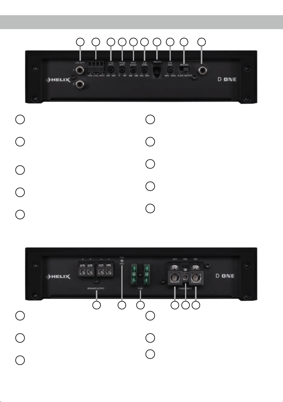
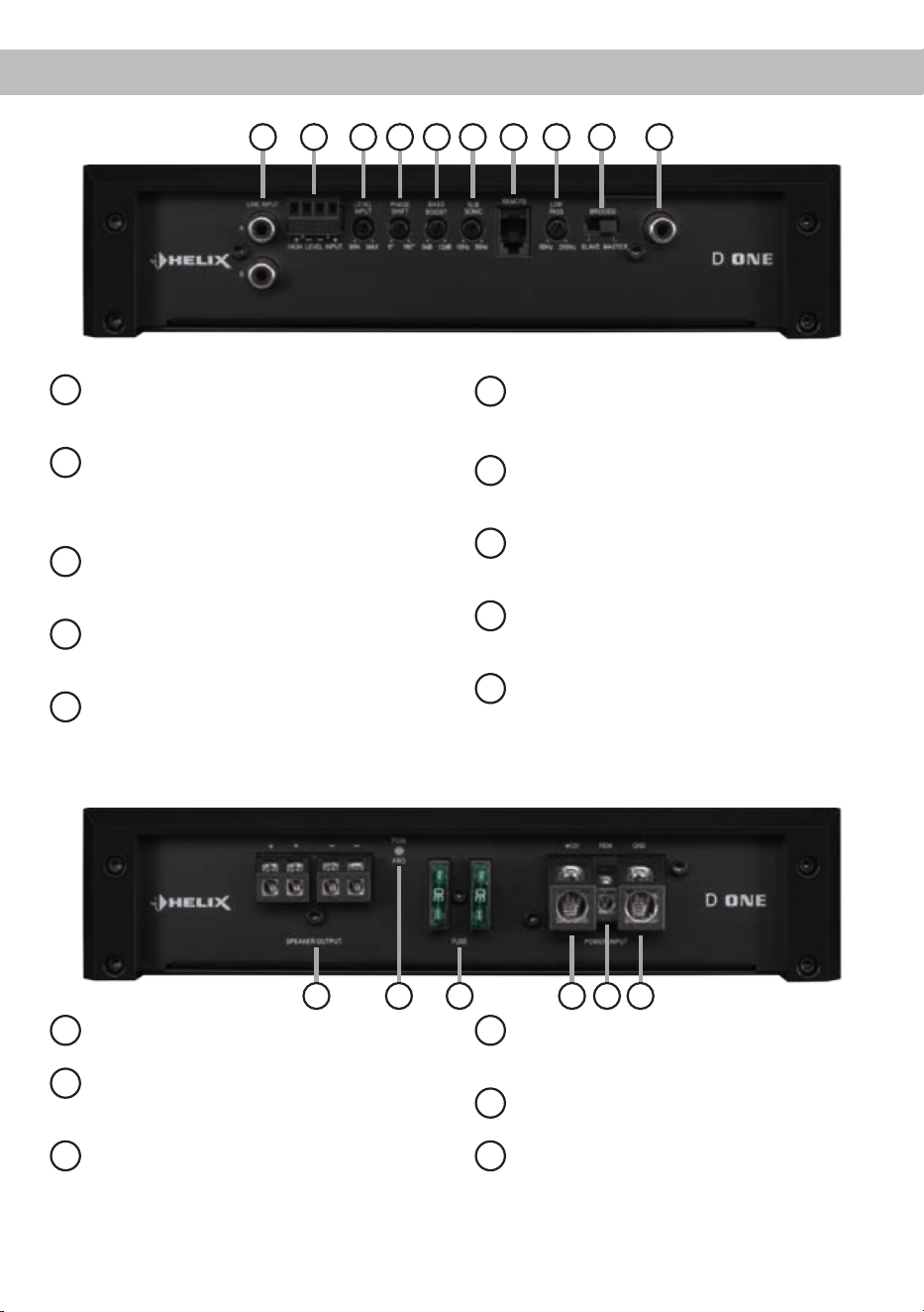
Anschluss- und Bedienelemente
3
11
Speaker Output
Lautsprecherausgang für den Anschluss von
Subwoofern.
12
Power & Protect LED
Die Power & Protect LED zeigt den
Betriebszustand des Verstärkers an.
13
Fuse
Eingangssicherungen zum Schutz vor
geräteinternen Fehlern. Der Sicherungswert
beträgt 2 x 30 Ampere.
14
+12 V
Anschluss für das Versorgungsspannungs-
kabel +12 V der Batterie.
15
REM
Anschluss für die Remoteleitung.
16
GND
Anschluss des Massekabels (Minuspol der
Batterie oder Fahrzeugchassis).
1
Line Input
Cinch-Eingänge zum Anschluss eines
Vorverstärkersignals.
2
Highlevel Input
Hochpegel-Lautsprechereingang zum An-
schluss von Werksradios oder Radios ohne
Vorverstärkerausgänge.
3
Level Input
Regler zum Einstellen der Eingangsempnd-
lichkeit des Line und Highlevel Inputs.
4
Phase Shift
Regler zum Einstellen der Phase von 0° bis
180°.
5
Bass Boost
Regler zum Einstellen der Bassanhebung
von 0 bis 12 dB.
6
Subsonic
Regler zum Einstellen des Subsoniclters
von 10 Hz bis 50 Hz.
7
Remote
Eingang zum Anschluss der mitgelieferten
Fernbedienung zur Lautstärkeregelung.
8
LPF
Regler zum Einstellen des Tiefpasslters von
50 Hz bis 250 Hz.
9
Master / Slave Modus
Schalter um zwei D ONE Verstärker im
Brüc kenbetrieb zu betreiben.
10
Mono Cinch In-/Output
Mono Cinch Signalein- oder -ausgang für den
Brückenbetrieb im Master / Slave Modus.
11 12 1513 14 16
1 2 5 7 8 93 4 6 10
1
Line Input
2-Kanal Vorverstärkereingang zum Anschluss von
Signalquellen, wie z.B. Radios, die mit dem/den
Vorverstärkerausgang/-ausgängen bzw. Line Out-
puts der Signalquelle verbunden werden können.
Achtung: Eine gleichzeitige Verwendung der
Hochpegel- und Vorverstärkersignaleingänge ist
nicht möglich und kann zu Schäden an Ihrem Au-
toradio führen.
2
Highlevel Input
2-Kanal Hochpegel-Lautsprechereingang. Mit Hilfe
dieses Eingangs kann der Verstärker direkt an
die Lautsprecherausgänge eines Werks- / Nach-
rüstradios angeschlossen werden, sofern dieses
nicht über Vorverstärkerausgänge verfügt. Der
Highlevel-Eingang verfügt über den ADEP-Schalt-
kreis (Advanced Diagnostics Error Protection), der
dafür sorgt, dass der Verstärker auch von OEM
Radios als Lautsprecher erkannt wird und somit im
Werksradio keine Funktionen deaktiviert werden
und auch kein Eintrag im Fehlerspeicher des Fahr-
zeugs erzeugt wird.
Bei Verwendung dieses Eingangs schaltet der Ver-
stärker bei allen handelsüblichen Radios automa-
tisch ein, so dass dieser nicht über den Remote-
Eingang (REM) eingeschaltet werden muss.
Achtung: Verwenden Sie zum Anschluss aus-
schließlich den mitgelieferten Stecker mit integrier-
ten Schraubklemmen.
Achtung: Eine gleichzeitige Verwendung der
Hochpegel- und Vorverstärkersignaleingänge ist
nicht möglich und kann zu Schäden an Ihrem Auto-
radio führen.
3
Level Input
Mit Hilfe dieses Reglers kann die Eingangsempnd-
lichkeit an die Ausgangsspannung des angeschlos-
senen Radios angepasst werden.
Dieser Regler ist kein Lautstärkeregler, sondern
dient nur der Anpassung. Der Regelbereich des
Cinch-Eingangs (Line Input) liegt zwischen
0,5 - 6 Volt und 1 - 14 V für den Hochpegeleingang
(Highlevel Input). Sofern die Lautsprecherausgän-
ge eines üblichen Radios verwendet werden (High-
level), empfehlen wir eine Einstellung von ca. 9 Volt.
Dafür stellen Sie den Drehregler vom Linksan-
schlag aus im Uhrzeigersinn etwa auf die 9 Uhr-
Position ein.
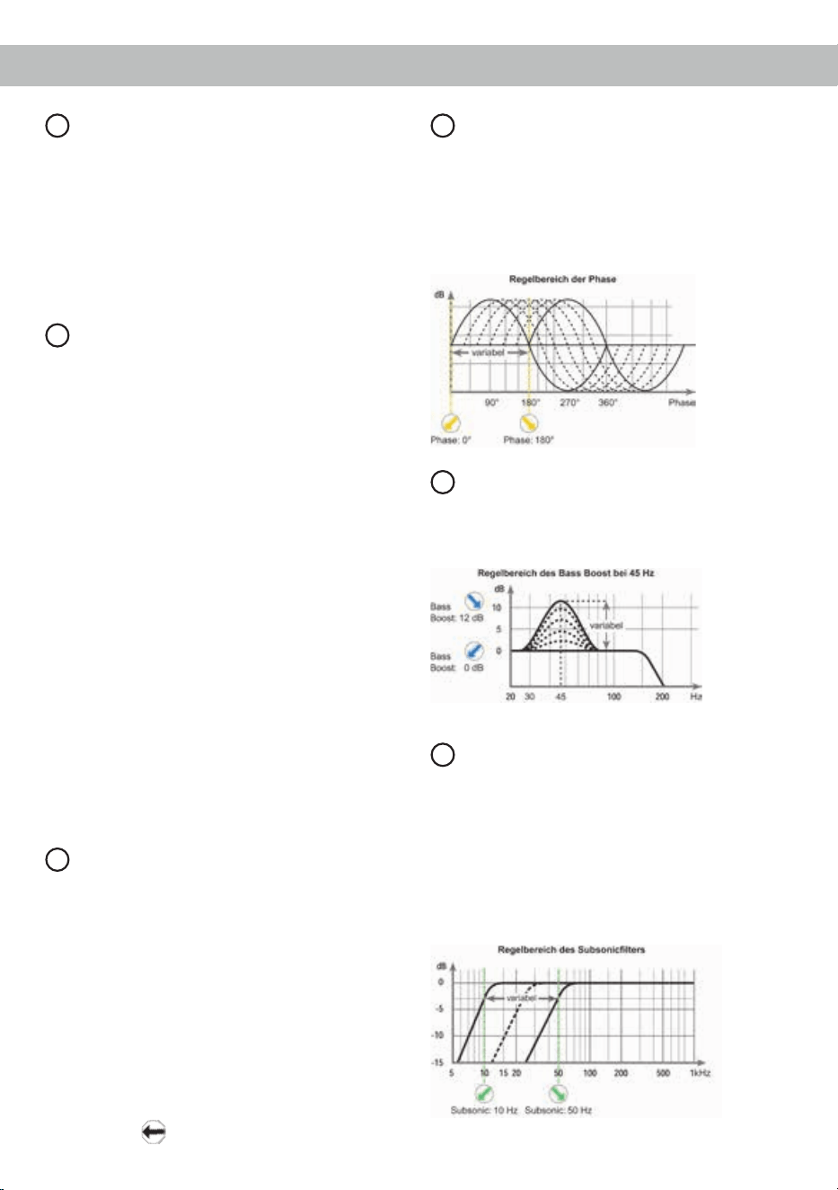
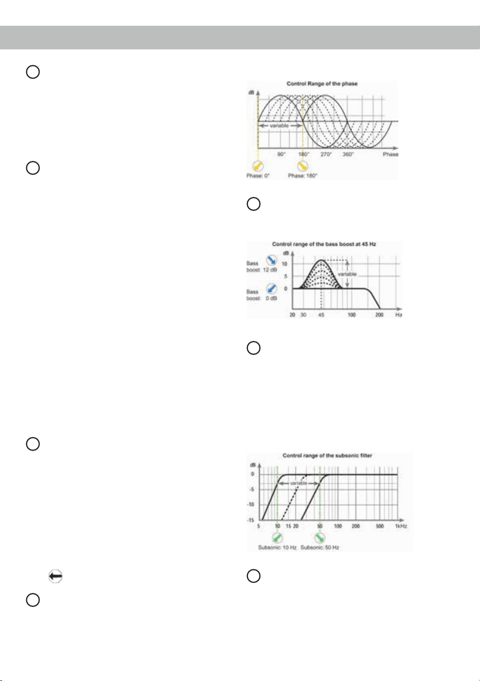
4
Phase Shift
Mit Hilfe dieses Reglers kann die Phase von 0° bis
180° eingestellt werden. Dies ermöglicht eine bes-
sere Ankopplung des Subwoofers an die Tieftonwie-
dergabe der restlichen Lautsprechersysteme und
verhindert ein Auslöschen der tiefen Frequenzen
aufgrund falscher Phasenlage.
5
Bass Boost
Mit Hilfe dieses Reglers kann die Basswiedergabe
bei einer Mittenfrequenz von 45 Hz um 0 bis 12 dB
angehoben werden.
6
Subsonic
Mit Hilfe dieses Reglers kann der Subsoniclter
von 10 Hz bis 50 Hz eingestellt werden. Dieses
Filter dient dazu, sehr tiefe Frequenzen außerhalb
des Hörspektrums herauszultern und so den Sub-
woofer und den Verstärker zu entlasten, um mehr
Leistung für die wahrnehmbaren Frequenzen zur
Verfügung zu haben. Dieser Regler ist immer aktiv
und muss zwingend eingestellt werden.
Inbetriebnahme und Funktionen
4
5
7
Remote
Eingang zum Anschluss der im Lieferumfang ent-
haltenen Fernbedienung. Mit Hilfe dieser Fernbe-
dienung lässt sich die Lautstärke des Subwoofers
kontrollieren.
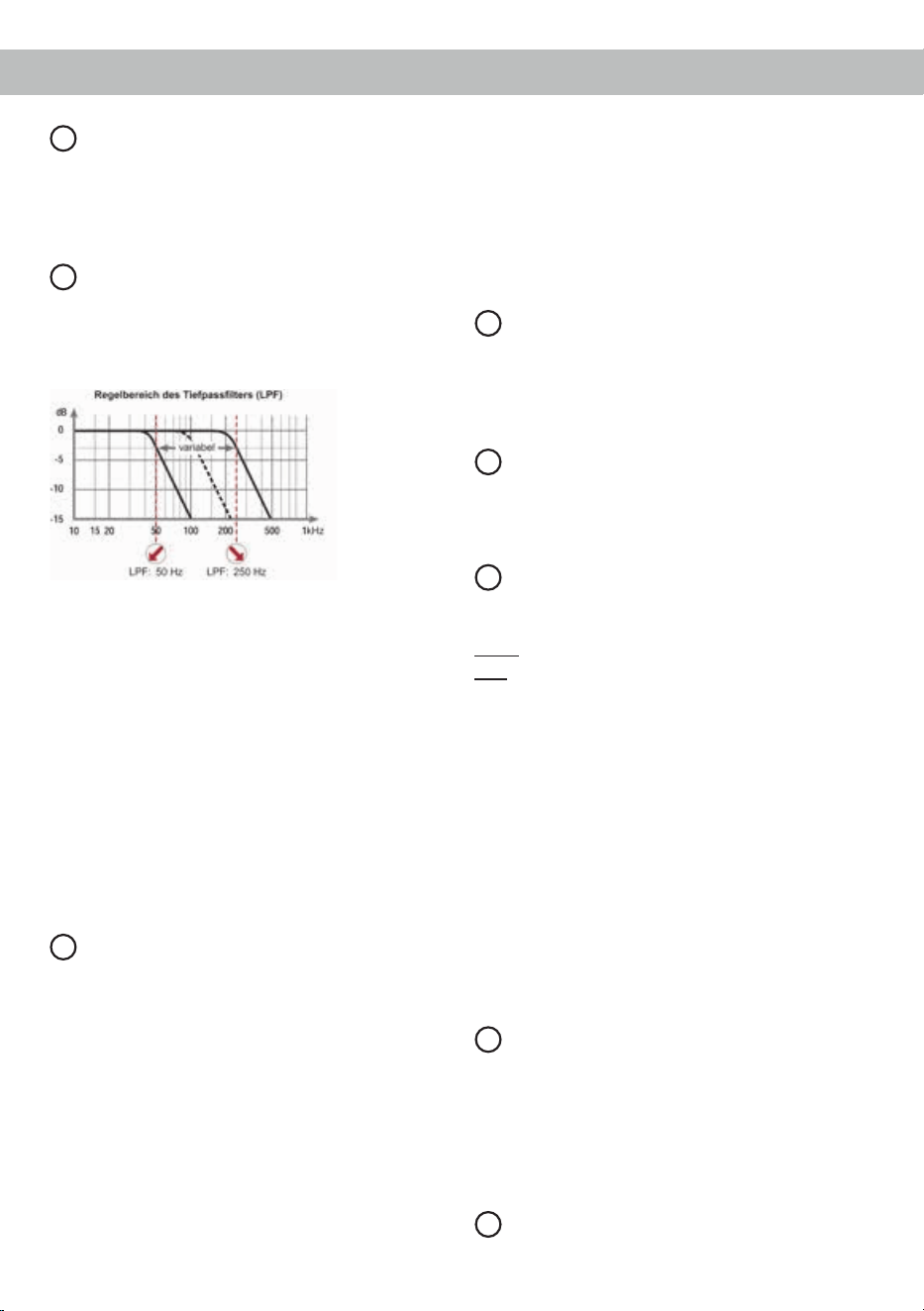
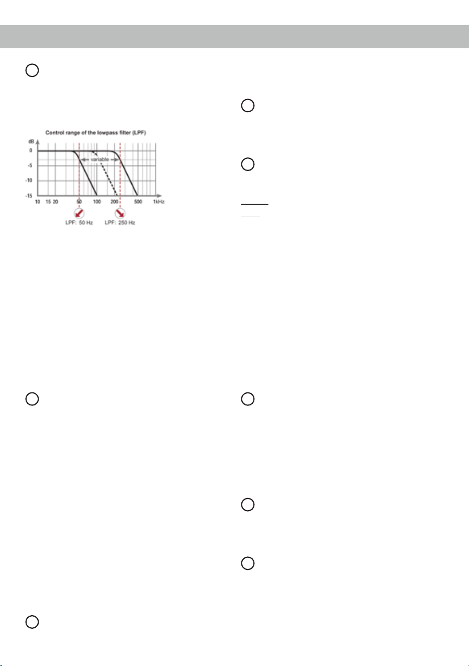
8
LPF
Mit Hilfe dieses Reglers kann das Tiefpasslter von
50 Hz bis 250 Hz eingestellt werden. Dieser Reg-
ler ist immer aktiv und muss zwingend eingestellt
werden.
Das Tiefpasslter bildet in Verbindung mit dem Sub-
soniclter in jedem Fall einen Bandpass.
So kann mit Hilfe dieser beiden Regler ein Band-
pass von 10 Hz bis 250 Hz gebildet werden.
Achtung: Bitte vergewissern Sie sich, dass beim
Einstellen eines Bandpasses die Übernahmefre-
quenzen von Subsonic- und Tiefpasslter minde-
stens zwei Oktaven auseinander liegen, um einen
Pegelverlust zu vermeiden! Das heißt: Wird das
Tiefpasssignal z.B. auf 100 Hz eingestellt, so sollte
der Subsoniclter um mindestens zwei Oktaven
tiefer auf ca. 25 Hz eingestellt werden. (1 Oktave =
Frequenzverdopplung oder Frequenzhalbierung).
9
Master / Slave Modus
Bei der D ONE handelt es sich um einen „real-
mono“ Verstärker, der sich über den Master / Slave
Modus mit einer zweiten D ONE verschalten lässt
um die Ausgangsleistung, je nach Lautsprecher-
konguration, mehr als zu verdoppeln. Um zwei
Verstärker im Master / Slave Betrieb zu betreiben,
werden diese über die In/Out Buchse (siehe Sei-
te 5, Punkt 10; Mono Cinch In- / Output) mit einem
Cinchkabel verbunden. Der Verstärker, der auf Ma-
ster geschaltet ist, übernimmt nun die komplette
Regelung (Aktivweiche, Bass Boost usw.). Alle Fil-
tereinstellungen des Verstärkers im Slave Modus
werden dabei deaktiviert.
Achtung: Bitte immer darauf achten das ein Ver-
stärker auf Master und der andere auf Slave ge-
schaltet ist. In diesem Modus liegt die Minimalim-
pedanz bei 2 Ohm.
Hinweis: Wird der Verstärker einzeln betrieben,
muss die Schalterstellung „Master“ gewählt werden.
Kongurationsbeispiele nden Sie auf Seite 7 ff.
10
Mono Cinch In- / Output
Dieser Anschluss dient als Signalein- oder -aus-
gang zum Anschluss eines weiteren D ONE Ver-
stärkers im Brückenbetrieb (siehe Seite 5, Punkt 9;
Master / Slave Modus).
11
Speaker Output
Dieser Anschluss dient als Lautsprecherausgang.
Die minimale Lastimpedanz darf 1 Ohm (im Ma-
ster / Slave Modus 2 Ohm) nicht unterschreiten.
12
Power & Protect LED
Die Power & Protect LED zeigt den Betriebszustand
des Verstärkers an.
Grün: Verstärker eingeschaltet und betriebsbereit.
Rot: Es besteht eine Fehlfunktion des Verstär-
kers. Diese Fehlfunktion kann unterschied-
liche Ursachen haben, da die D ONE mit
verschiedenen elektronischen Schutzschal-
tungen ausgestattet ist. Diese schalten
den Verstärker bei Überhitzung, Über- und
Unterspannung, Kurzschluss am Lautspre-
cherausgang und Fehlanschluss ab. Prüfen
Sie in diesem Fall alle Anschlüsse auf Feh-
ler, wie z.B. Kurzschlüsse, fehlerhafte Ver-
bindungen oder Falscheinstellungen und
Übertemperatur. Sollte sich der Verstärker
nach Beseitigung der Fehlerquelle nicht
wieder einschalten lassen, liegt ein Defekt
vor.
13
Fuse
Die Eingangssicherungen sind parallel geschaltet
und schützen vor einem geräteinternen Fehler, d.h.
die Anlage muss mit einer zusätzlichen Sicherung
in Nähe der Batterie (max. 30 cm entfernt) abgesi-
chert werden. Der Sicherungswert für den Verstär-
ker beträgt 2 x 30 Ampere.
14
+12 V
Das +12 V Versorgungskabel ist am Pluspol der

6
Die HELIX D ONE wird wie nachfolgend be-
schrieben an das Autoradio angeschlossen.
Achtung: Für die Durchführung der nachfolgenden
Schritte werden Spezialwerkzeuge und Fachwissen
benötigt. Um Anschlussfehler und Beschädigungen
zu vermeiden, fragen Sie im Zweifelsfall Ihren Ein-
bauspezialisten und beachten Sie zwingend die
allgemeinen Anschluss- und Einbauhinweise (siehe
Seite 2).
1. Anschluss der Vorverstärkereingänge
Diese Eingänge (Line Input) können mit ent-
sprechenden Kabeln (RCA / Cinch-Kabel) an
die Vorverstärker- / Lowlevel- / Cinch-Ausgän-
ge des Radios angeschlossen werden.
Dabei müssen beide Eingänge belegt werden.
Die Einschaltautomatik des Verstärkers funk-
tioniert bei den Vorverstärkereingängen nicht,
so dass der Remote-Eingang (REM) zwingend
belegt werden muss.
Achtung: Eine gleichzeitige Verwendung der
Hochpegel- und Vorverstärkersignaleingänge
ist nicht möglich und kann zu Schäden an Ihrem
Autoradio führen.
2. Anschluss der Highlevel-Lautsprecherein-
gänge
Die Hochpegel-Lautsprechereingänge A und B
(High level Input) können direkt mit den Laut-
sprecherausgängen des Werks- bzw. Nachrüst-
radios mit Hilfe entsprechender Kabel (Laut-
sprecherkabel mit max. 1 mm² Querschnitt)
verbunden werden.
Dabei müssen beide Eingänge belegt werden.
Achten Sie bitte auf eine korrekte Polung!
Wenn Sie einen Anschluss verpolen, kann da-
durch die Funktion des Verstärkers beeinträch-
tigt werden. Bei Verwendung dieses Eingangs
muss der Remote-Eingang (REM) nicht belegt
werden, da sich der Verstärker automatisch ein-
schaltet, sobald ein Lautsprechersignal anliegt.
3. Einstellung der Eingangsempndlichkeit
Achtung: Es ist zwingend notwendig die
Eingangsempndlichkeit der D ONE an die
Signalquelle anzupassen, um Schäden am
Verstärker zu vermeiden.
Um die Eingangsempndlichkeit zu verändern,
verwenden Sie den Drehregler (siehe Seite 4,
Punkt 3; Level Input). Die Einstellung dieses
Reglers beeinusst sowohl die Vorverstärker-
eingänge (Line Input) als auch die Hochpegel-
Lautsprechereingänge (Highlevel Input)!
Sofern die Lautsprecherausgänge eines üb-
lichen Radios verwendet werden (Highlevel),
empfehlen wir eine Einstellung von ca. 9 Volt.
Dafür stellen Sie den Drehregler vom Linksan-
schlag aus im Uhrzeigersinn etwa auf die 9 Uhr-
Position ein.
4. Anschluss der Stromversorgung
Vor dem Anschluss des +12 V Versorgungs-
kabels an das Bordnetz muss die Autobatte-
rie abgeklemmt werden.
Das +12 V Stromkabel ist am Pluspol der Bat-
terie anzuschließen. Die Plusleitung sollte in
einem Abstand von max. 30 cm von der Batterie
mit einer Hauptsicherung abgesichert werden.
Batterie anzuschließen. Der empfohlene Quer-
schnitt beträgt mindestens 10 mm².
15
REM
Die Remoteleitung wird mit dem Remote-Ausgang /
Antennenanschluss des Steuergerätes (Radio) ver-
bunden. Dieser ist nur aktiviert, wenn das Steuer-
gerät eingeschaltet ist. Somit wird der Verstärker
mit dem Steuergerät ein- und ausgeschaltet. Dieser
Eingang muss nicht belegt werden, wenn der
Hochpegel-Lautsprechereingang (Highlevel Input)
benutzt wird.
16
GND
Das Massekabel sollte am zentralen Massepunkt
(dieser bendet sich dort wo der Minuspol der Bat-
terie zum Metallchassis des Kfz geerdet ist) oder an
einer blanken, von Lackresten befreiten Stelle des
Kfz-Chassis angeschlossen werden. Der empfohle-
ne Querschnitt beträgt mindestens 10 mm².
Einbau und Installation
Inbetriebnahme und Funktionen

7
Der Wert der Sicherung errechnet sich aus der
maximalen Stromaufnahme der gesamten Car-
Hi Anlage (D ONE = max. 60 A RMS bei 12 V
Bordnetz).
Verwenden Sie bei kurzen Leitungen (< 1 m)
einen Querschnitt von mindestens 10 mm². Bei
längeren Leitungen empfehlen wir einen Quer-
schnitt von 16 mm² bis 25 mm².
Das Massekabel (gleicher Querschnitt wie
das +12 V Kabel) muss an einem blanken,
von Lackresten befreiten Massepunkt des
Kfz-Chassis oder direkt an dem Minuspol der
Autobatterie angeschlossen werden.
5. Anschluss des Remote-Eingangs
Der Remote-Eingang (REM) muss mit dem Re-
mote-Ausgang des Radios verbunden sein, so-
fern die Vorverstärkereingänge des Verstärkers
als Signaleingänge genutzt werden. Es wird
dringend davon abgeraten, den Remote-Ein-
gang des Verstärkers über das Zündungsplus
des Fahrzeugs zu steuern, um Störgeräusche
beim Ein- und Ausschalten zu vermeiden. Bei
Verwendung des Highlevel-Eingangs ( Highlevel
Input) muss der Remote-Eingang nicht belegt
werden, sofern das angeschlossene Radio
über BTL-Ausgangsstufen verfügt.
6. Anschluss eines Verstärkers im Master / Sla-
ve Modus (optional)
Um den Verstärker mit einem weiteren D ONE
Verstärker zu verschalten führen Sie die fol-
genden Schritte durch.
1. Denieren Sie den Verstärker, welcher mit
der Signalquelle (Radio) verbunden ist, als
Master, indem Sie den Master / Slave Modus
Schalter auf „Master“ stellen (siehe Seite 5,
Punk 9; Master / Slave Modus).
2. Stellen sie den Master / Slave Modus Schal-
ter des anderen Verstärkers auf „Slave“.
3. Verbinden Sie mit einem Cinchkabel den
Mono Cinch In- / Output der beiden Verstär-
ker (siehe Seite 10, Punkt 10; Mono Cinch
In- / Output).
4. Nehmen Sie sämtliche Filtereinstellungen
am „Master-Verstärker“ vor. Alle Filterein-
stellungen des Verstärkers im Slave Modus
werden automatisch deaktiviert.
Kongurationsbeispiele nden Sie auf Seite 9.
7. Anschluss der Lautsprecherausgänge
Die Lautsprecherausgänge können direkt mit
den Lautsprecherleitungen verbunden werden.
Hinweis: Die Lautsprecherausgänge sind in-
tern parallel geschaltet. D.h. an beiden Plus-
Ausgängen (+) bzw. beiden Minus-Ausgän-
gen (-) liegt jeweils das gleiche Signal an.
Verbinden Sie niemals die Lautsprecherlei-
tungen mit der Kfz-Masse (Fahrzeugkaros-
serie). Dies kann Ihren Verstärker zerstören.
Sofern Sie zwei Lautsprecher parallel anschlie-
ßen, achten Sie bitte darauf, dass die Phase
identisch ist, d.h. Plus zu Plus und Minus zu
Minus. Vertauschen von Plus und Minus hat
einen Totalverlust der Basswiedergabe zur Fol-
ge. Der Pluspol ist bei den meisten Lautspre-
chern gekennzeichnet. Die Gesamtimpedanz
darf 1 Ohm nicht unterschreiten (2 Ohm im Ma-
ster / Slave Modus), da sonst die Schutzschal-
tung des Verstärkers aktiviert wird. Beispiele
für den Lautsprecheranschluss nden Sie auf
Seite 7 ff.
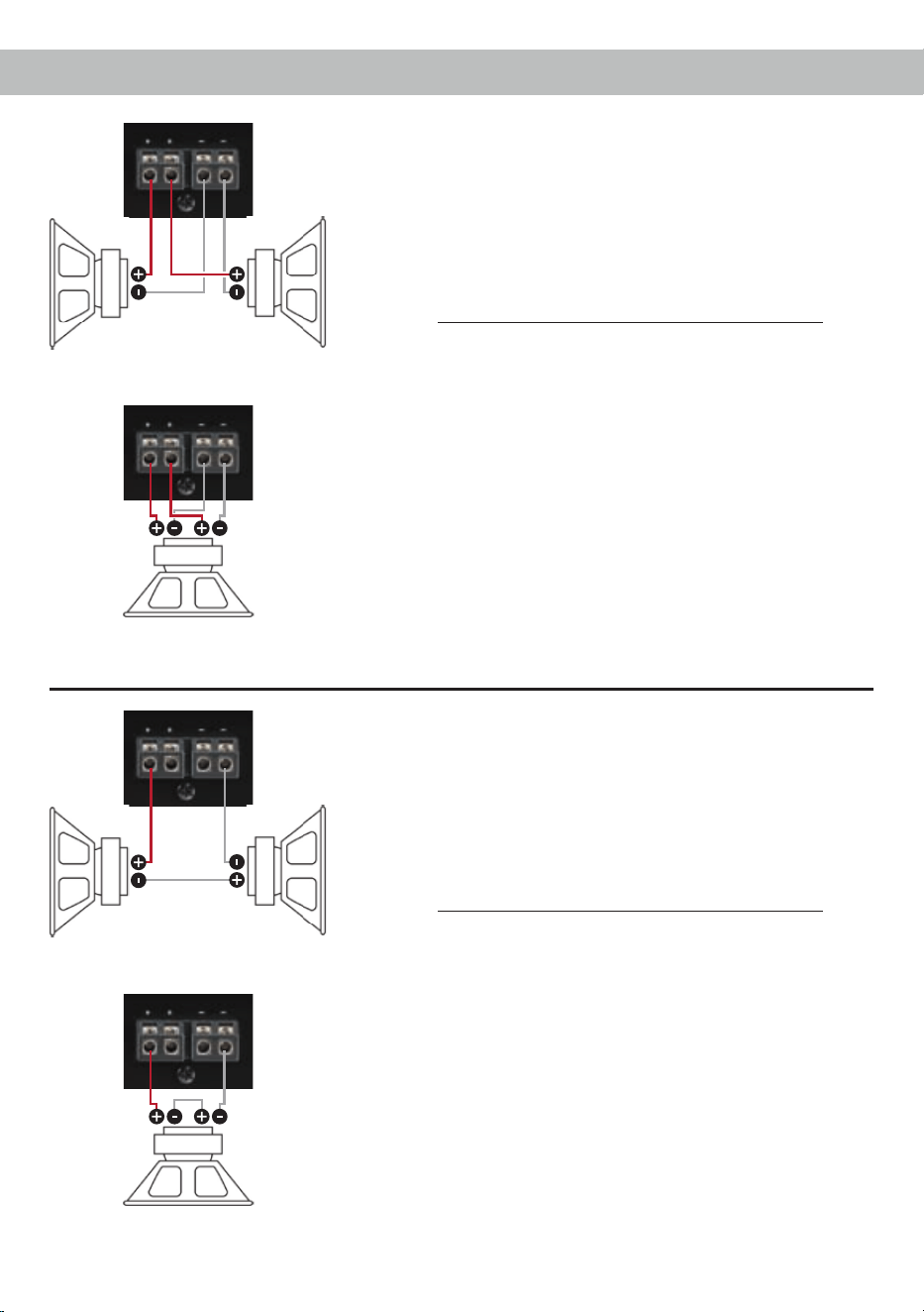
Kongurationsbeispiele
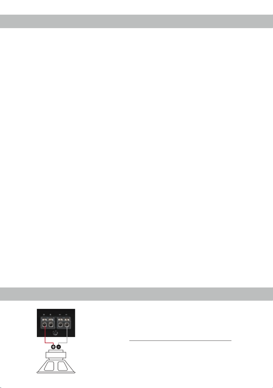
Mono
Subwoofer mit einer Schwingspule (Single Voice Coil)
Maximale Ausgangsleistung dieser Konguration:
1 x 4 Ohm: 200 / 400 Watt
1 x 2 Ohm: 340 / 680 Watt
1 x 1 Ohm: 530 / 1.060 Watt
8
Kongurationsbeispiele
Parallelbetrieb
Zwei Subwoofer mit einer Schwingspule (Single Voice
Coil) oder ein Subwoofer mit Doppelschwingspule (Dual
Voice Coil) werden parallel geschaltet.
Hinweis: Die Parallelschaltung von zwei Schwingspulen
führt zur Halbierung der Impedanz!
Maximale Ausgangsleistung dieser Konguration:
Zwei Subwoofer mit 1 x 4 Ohm entsprechen einer
Gesamtimpedanz von 2 Ohm: 340 / 680 Watt
Ein Subwoofer mit 2 x 4 Ohm entspricht ebenso einer
Gesamtimpedanz von 2 Ohm: 340 / 680 Watt
Zwei Subwoofer mit 1 x 2 Ohm entsprechen einer
Gesamtimpedanz von 1 Ohm: 530 / 1.060 Watt
Ein Subwoofer mit 2 x 2 Ohm entspricht ebenso einer
Gesamtimpedanz von 1 Ohm: 530 / 1.060 Watt
Hinweis: Das Parallelschalten von 1 Ohm Schwingspu-
len führt zu Abschaltung des Verstärkers.
Ein Subwoofer mit
Doppelschwingspule
(Dual Voice Coil)
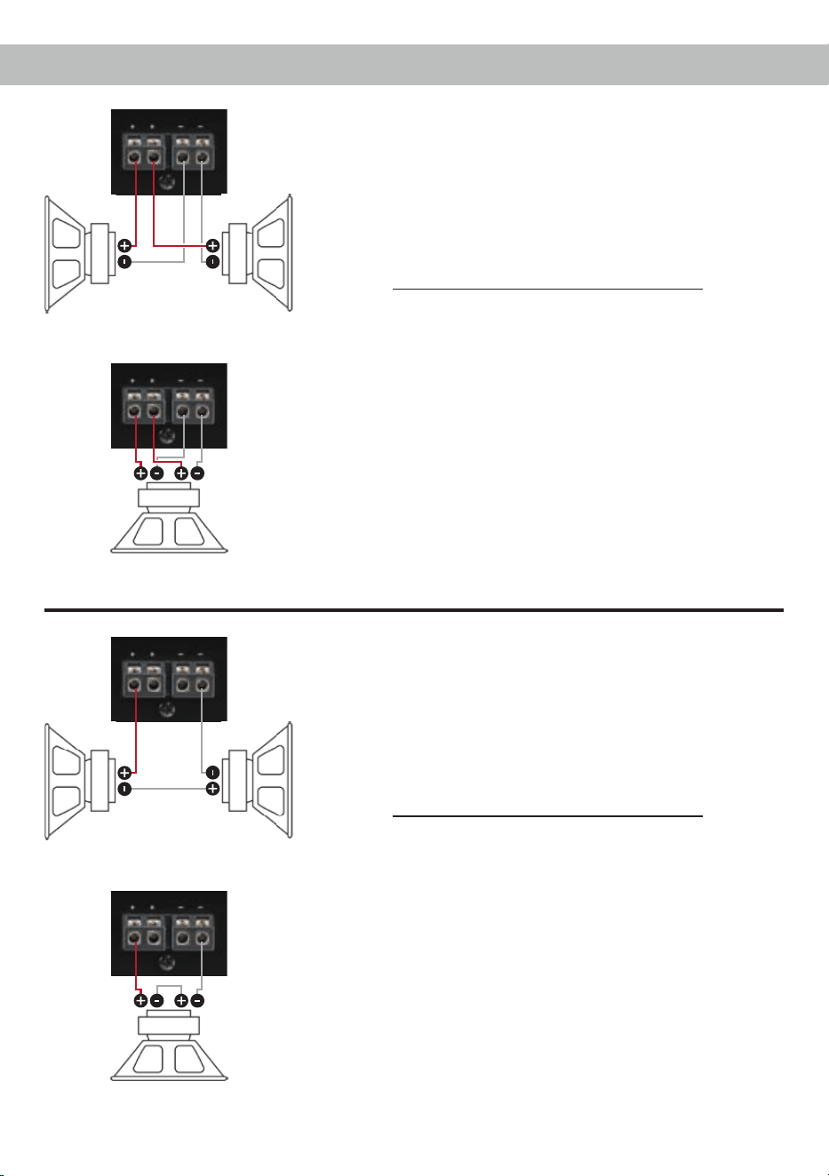
Reihenbetrieb
Zwei Subwoofer mit einer Schwingspule (Single Voice
Coil) oder ein Subwoofer mit Doppelschwingspule (Dual
Voice Coil) werden in Reihe geschaltet.
Hinweis: Die Reihenschaltung von zwei Schwingspulen
führt zur Verdopplung der Impedanz!
Maximale Ausgangsleistung dieser Konguration:
Zwei Subwoofer mit 1 x 2 Ohm entsprechen einer
Gesamtimpedanz von 4 Ohm: 200 / 400 Watt
Ein Subwoofer mit 2 x 2 Ohm entspricht ebenso einer
Gesamtimpedanz von 4 Ohm: 200 / 400 Watt
Zwei Subwoofer mit 1 x 1 Ohm entsprechen einer
Gesamtimpedanz von 2 Ohm: 340 / 680 Watt
Ein Subwoofer mit 2 x 1 Ohm entspricht ebenso einer
Gesamtimpedanz von 2 Ohm: 340 / 680 Watt
Hinweis: Die Reihenschaltung von 4 Ohm Sub woofern
führt zu einer sehr geringen Ausgangsleistung des
Verstärkers und ist daher nicht empfehlenswert!
Ein Subwoofer mit
Doppelschwingspule
(Dual Voice Coil)
Zwei Subwoofer mit einer
Schwingspule
(Single Voice Coil)
Zwei Subwoofer mit einer
Schwingspule
(Single Voice Coil)

9
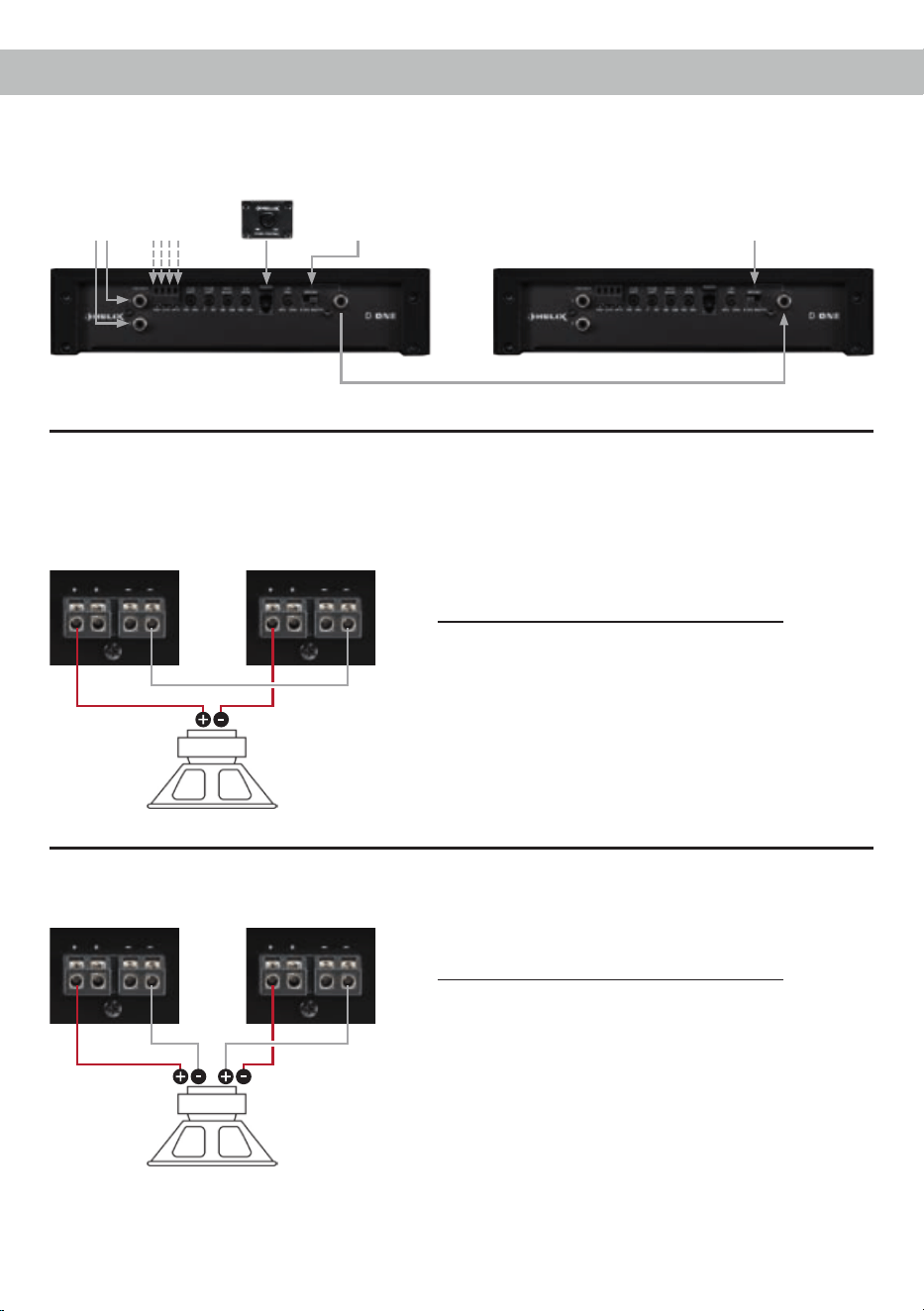
Kongurationsbeispiele für den Master / Slave Modus
Master Slave
Verstärkeranschluss im Master / Slave Modus
Signal vom Radio
(Cinch oder Highlevel)
Cinchkabel
Lautsprecheranschluss im Master / Slave Modus
Master Slave
Ein Subwoofer mit einer Schwingspule
(Single Voice Coil)
Maximale Ausgangsleistung dieser Konguration:
1 x 4 Ohm: 645 / 1.290 Watt
1 x 2 Ohm: 910 / 1.820 Watt
Hinweis: Die negativen Lautsprecherausgänge des
Verstärkers müssen in dieser Konguration miteinander
verbunden werden. Hierzu sollte der selbe Kabelquer-
schnitt gewählt werden, welcher auch für den Anschluss
des Subwoofers genutzt wird.
Master Slave
Ein Subwoofer mit Doppelschwingspule
(Dual Voice Coil)
Maximale Ausgangsleistung dieser Konguration:
2 x 4 Ohm: 400 / 800 Watt
2 x 2 Ohm: 680 / 1.360 Watt
2 x 1 Ohm: 1.060 / 2.120 Watt
Hinweis: Bei diesem Kongurationsbeispiel ist auch im
Master / Slave Modus eine 1 Ohm Konguration mög-
lich, jedoch nicht empfehlenswert!
Achtung: Die zweite Subwoofer-
schwingspule muss am „Slave-Ver-
stärker“ mit umgekehrter Polung ange-
schlossen werden!
Schalterstellung:
Master
Schalterstellung:
Slave

10
Leistung RMS / Max. Normalbetrieb Master / Slave Modus
(Ein Verstärker) (Zwei Verstärker)
- @ 4 Ohm .................................................................. 1 x 200 / 400 Watt 1 x 645 / 1.290 Watt
- @ 2 Ohm .................................................................. 1 x 340 / 680 Watt 1 x 910 / 1.820 Watt
- @ 1 Ohm .................................................................. 1 x 530 / 1.060 Watt –
Verstärkertechnologie ................................................. Class D
Eingänge .................................................................... 2 x Cinch
2 x Hochpegel-Lautsprechereingang
1 x Remote In
1 x Fernbedienungseingang
Ausgänge ................................................................... 1 x Lautsprecherausgang
Frequenzbereich......................................................... 10 Hz - 250 Hz
Bass Boost ................................................................. 0 - 12 dB / 45 Hz
Tiefpass ...................................................................... 50 Hz - 250 Hz regelbar
Bandpass.................................................................... 10 Hz - 250 Hz regelbar
Subsonic ..................................................................... 10 Hz - 50 Hz regelbar
Phase ......................................................................... 0 - 180° regelbar
Flankensteilheit Subsonic / Tiefpass .......................... 12 dB/Okt.
Klirrfaktor (THD) ......................................................... 0,25 %
Signal- / Rauschabstand ............................................ 95 dB (A-bewertet)
Eingangsempndlichkeit ............................................. Hochpegel 1 - 14 Volt
Cinch 0,5 - 6 Volt
Dämpfungsfaktor ........................................................ 100
Eingangsimpedanz Cinch ........................................... 30 kOhm
Eingangsimpedanz Highlevel ..................................... 12 Ohm
Betriebsspannung....................................................... 9,6 - 16 Volt
Sicherung ................................................................... 2 x 30 A Maxi-Stecksicherung (FK3)
Abmessungen (H x B x T) .......................................... 53 x 250 x 230 mm
Zusätzliche Features .................................................. Aktive, regelbare Frequenzweiche, Bass Boost,
Phase Shift, Master / Slave Modus Schalter,
Highlevel-Eingang mit automatischer Einschaltung
und Advanced Diagnostics Error Protection (ADEP),
Basspegel-Kabelfernbedienung
Technische Daten
Die Garantieleistung entspricht der gesetzlichen
Regelung. Von der Garantieleistung ausgeschlos-
sen sind Defekte und Schäden, die durch Überla-
stung oder unsachgemäße Behandlung entstanden
sind. Eine Rücksendung kann nur nach vorheriger
Absprache in der Originalverpackung, einer de-
taillierten Fehlerbeschreibung und einem gültigen
Kaufbeleg erfolgen.
Technische Änderungen und Irrtümer vorbehalten!
Für Schäden am Fahrzeug oder Gerätedefekte, her-
vorgerufen durch Bedienungsfehler des Gerätes,
können wir keine Haftung übernehmen. Dieses
Produkt ist mit einer CE-Kennzeichnung versehen.
Damit ist das Gerät für den Betrieb in Fahrzeugen
innerhalb der Europäischen Union (EU) zertiziert.
Garantiehinweis

11
Dear Customer,
Congratulations on your purchase of this innovative
and high-qual ity HELIX product.
The HELIX D ONE combines best quality, excellent
manufacturing and state-of-the-art technology.
Thanks to more than 30 years of experience in re-
search and development of audio products this am-
plier generation sets new standards with respect to
price /performance ratio.
We wish you many hours of enjoyment with your
new HELIX amplier.
Yours,
AUDIOTEC FISCHER Team
General installation instructions for HELIX
components
To prevent damage to the unit and possible injury,
read this manual carefully and follow all installation
instructions. This product has been checked for
proper function prior to shipping and is guaranteed
against manufacturing defects.
Before starting your installation, disconnect the
battery’s negative terminal to prevent damage
to the unit, re and/or risk of injury. For a proper
performance and to ensure full warranty coverage,
we strongly recommend to get this product installed
by an authorized HELIX dealer.
Install your D ONE in a dry location with sufcient
air circulation for proper cooling of the equipment.
The amplier should be secured to a solid mounting
surface using proper mounting hardware. Before
mounting, carefully examine the area around and
behind the proposed installation location to ensure
that there are no electrical cables or components,
hydraulic brake lines or any part of the fuel tank lo-
cated behind the mounting surface. Failure to do so
may result in unpredictable damage to these com-
ponents and possible costly repairs to the vehicle.
General instruction for connecting the HELIX
D ONE amplier
The HELIX D ONE amplier may only be installed
in vehicles which have a 12 Volts negative terminal
connected to the chassis ground. Any other system
could cause damage to the amplier and the electri-
cal system of the vehicle.
The positive cable from the battery for the complete
system should be provided with a main fuse at a
distance of max. 30 cm from the battery. The val-
ue of the fuse is calculated from the maximum total
current input of the car audio system.
Use only suitable cables with sufcient cable
cross-section for the connection of the HELIX
D ONE. The fuses may only be replaced by iden-
tically rated fuses (2 x 30 A) to avoid damage of
the amplier.
Prior to installation, plan the wire routing to avoid
any possible damage to the wire harness. All
cabling should be protected against possible crush-
ing or pinching hazards. Also avoid routing cables
close to potential noise sources such as electric
motors, high power accessories and other vehicle
harnesses.
Congratulations!
General instructions
12
Connectors and control units
11
Speaker Output
Speaker outputs for connecting subwoofers.
12
Power & Protect LED
This LED indicates the operating mode of the
amplier.
13
Fuse
Input fuses - 2 x 30 Ampere.
14
+12 V
Connector for the +12 V power cable of the
positive terminal of the battery.
15
REM
Connector for the remote cable.
16
GND
Connector for the ground cable (negative
terminal of the battery or metal body of the
vehicle).
1
Line Input
RCA inputs for connecting lowlevel line
signals.
2
Highlevel Input
Highlevel speaker inputs for connecting a
factory radio or an aftermarket radio without
lowlevel line outputs.
.
3
Level Input
Control for adjusting the input sensitivity of
the lowlevel Line and Highlevel Inputs.
4
Phase Shift
Control for adjusting the phase from 0° to
180°.
5
Bass Boost
Control for adjusting the bass boost from 0 to
12 dB.
6
Subsonic
Control for adjusting the subsonic lter from
10 to 50 Hz.
7
Remote
Input for connecting the included cable
remote control for volume adjustment.
8
LPF
Control for adjusting the lowpass lter from
50 to 250 Hz.
9
Master / Slave Mode
Switch for operating two D ONE ampliers in
bridge mode.
10
Mono RCA/Cinch In-/Output
Mono RCA/Cinch signal in- or output for
bridge mode operation in Master / Slave
Mode.
11 12 1513 14 16
1 2 5 7 8 93 4 6 10
13
Initial start-up and functions
1
Line Input
2-channel lowlevel line input to connect signal
sourc es such as head units / radios / DSPs.
Important: It is strictly forbidden to use the High-
level Input and lowlevel Line Input at the same time.
This may cause severe damage to the lowlevel line
outputs of your head unit / car radio.
2
Highlevel Input
2-channel highlevel loudspeaker input to connect
the amplier directly to the loudspeaker outputs of
OEM / aftermarket radios that do not have any low-
level line outputs.
The Highlevel Input is equipped with our proprietary
ADEP circuit (Advanced Diagnostics Error Protec-
tion) which ensures that the car radio detects the
amplier as a speaker and thus neither any function
of the radio (e.g. fader) will be deactivated nor any
error log in the CPU of the car will be created.
If this input is used the remote input (REM) does
not need to be connected as the amplier will
automatically turn on once a loudspeaker signal is
applied.
Attention: Solely use the pluggable screw-terminal
for the highlevel connector which is included in de-
livery!
Important: It is strictly forbidden to use the High-
level Input and lowlevel Line Input at the same time.
This may cause severe damage to the lowlevel line
outputs of your car radio.
3
Level Input
This control is used to adapt the input sensitivity to
the output voltage of the connected signal source.
This is not a volume control, it´s only for adjusting
the amplier gain. The control range of the RCA /
Line Input (lowlevel) is 0.5 - 6 Volts and 1 - 14 Volts
for the Highlevel Input.
If the Highlevel Input is used in combination with a
standard car radio we recommend an input sensitiv-
ity of roughly 9 Volts. For this purpose, turn the
control from max. CCW position to 9 o’clock posi-
tion.
4
Phase Shift
This control is used to adjust the phase from 0° to
180°. This allows to match the phase of the sub-
woofer with the other speakers thus avoiding any
cancellations in the frequency response due to
phase shifts.
5
Bass Boost
This control is used to increase the bass response
at a center frequency of 45 Hz from 0 to 12 dB.
6
Subsonic
This control is used to adjust the crossover frequen-
cy of the subsonic lter from 10 Hz to 50 Hz. The
subsonic lter cuts off very low frequencies which
aren’t audible and therefore relieves the amplier
and also the subwoofer. Additionally the amplier
will have more power available for the audible fre-
quencies. This control is always activated and its
adjustment is mandatory.
7
Remote
This input is used to connect the included remote
control. The remote control allows you to control the
volume of the amplier.
14
Initial start-up and functions
8
LPF
This control is used to adjust the crossover frequen-
cy of the lowpass lter from 50 Hz to 250 Hz. This
control is always activated and its adjustment is
mandatory.
In combination with the subsonic lter, the lowpass
lter creates a bandpass in any case. By adjusting
the subsonic (control 6) and lowpass (control 8) l-
ter any bandpass between 10 Hz and 250 Hz can
be realized.
Caution: To avoid a loss of gain make sure that the
crossover frequencies of the subsonic and lowpass
lters do have an interval of at least two octaves
when generating a bandpass. That means if the
lowpass is adjusted to 100 Hz the subsonic should
be adjusted to 25 Hz or less (one octave = doubled
frequency or halved frequency).
9
Master / Slave Mode
The HELIX D ONE amplier is a “real-mono” ampli-
er and can be connected to a second D ONE via
the Master / Slave Mode by which the output power
is more than doubled, depending on the speaker
conguration. In order to operate two ampliers in
this mode, they must be connected with a RCA /
Cinch cable (see page 14, item 10; Mono Cinch In- /
Output). The amplier which is set as “Master” as-
sumes the complete control (active crossover, bass
boost etc.) for both amps. All lter adjustments of
the amplier which operates in “Slave” mode will be
deactivated.
Attention: Make sure that one amplier is adjusted
as “Master” and the other one as “Slave”. In this
mode the minimum speaker impedance is 2 Ohms.
Note: If the amplier operates individually the Mas-
ter / Slave Mode switch must be set to “Master”.
10
Mono Cinch In- / Output
This connector serves as signal in- or -output for
connecting a further D ONE amplier in bridge
mode (see page 14, item 9; Master / Slave Mode).
11
Speaker Output
Speaker outputs to connect a subwoofer. The
minimum load impedance must not be lower than
1 Ohm (2 Ohms in Master / Slave Mode).
12
Power & Protect LED
The power and protect LED indicates the operating
mode of the amplier.
Green: The amplier is ready for operation.
Red: A malfunction has occurred. A malfunction
may have different causes as the HELIX
D ONE is equipped with several protec-
tion circuits. These protections shut off
the amplier in case of overheating, over-
and undervoltage, short-circuit on loud-
speakers and false connection. Please
check for connecting failures such as
short-circuits, wrong connections, wrong
adjustments and over temperature. If the
amplier does not turn on it is defective
and has to be sent to your local author-
ized dealer for repair service. A detailed
description of the malfunction and the
purchase receipt has to be attached.
13
Fuse
The input fuses are connected in parallel and pro-
vide protection against an internal fault of the de-
vice, therefore the system must be additionally pro-
tected by a further main fuse located close to the
battery (max. distance from battery: 30 cm / 12”).
The HELIX D ONE is equipped with 2 x 30 Ampere
fuses.
14
+12 V
Connect the +12 V power cable to the positive ter-
minal of the battery. Recommended cross section:
min. 10 mm² / AWG 8.
15
REM
The remote lead should be connected to the remote
output / automatic antenna (aerial positive) output
of the head unit / car radio. This is only activated
if the head unit is switched on. Thus the amplier
is switched on and off together with the head unit /
car radio. This input needn’t to be assigned if the

15
Installation
Connection of HELIX D ONE to the head unit /
car radio:
Caution: Carrying out the following steps will re-
quire special tools and technical knowledge. In or-
der to avoid connection mistakes and / or damage,
ask your dealer for assistance if you have any ques-
tions and follow all instructions in this manual (see
page 11). It is recommended that this unit will be
installed by an authorized HELIX dealer.
1. Connecting the lowlevel line inputs
Use the correct cable (RCA / Cinch cable) to
connect these inputs to the lowlevel line outputs
of your car radio. It is mandatory to use both
lowlevel line inputs.
The automatic turn-on circuit does not work
when using the lowlevel line inputs. In this case
the remote input (REM) has to be connected to
activate the HELIX D ONE.
Important: It is strictly forbidden to use the
Highlevel Input and lowlevel Line Input at the
same time. This may cause severe damage to
the lowlevel line outputs of your car radio.
2. Connecting the highlevel speaker inputs
The highlevel loudspeaker inputs can be con-
nected directly to the loudspeaker outputs of an
OEM or aftermarket radio using appropriate ca-
bles (loudspeaker cables with 1 mm² / AWG 18
max.).
It is mandatory to use both highlevel speaker
inputs. Make sure that the polarity is correct.
If one connection has reversed polarity it may
affect the performance of the amplier. If this
input is used the remote input (REM) does not
need to be connected as the amplier will au-
tomatically turn on once a loudspeaker signal
is applied.
3. Adjustment of the input sensitivity
Attention: It is mandatory to properly adapt
the input sensitivity of the D ONE to the sig-
nal source in order to avoid damage to the
amplier.
If you want to change the input sensitivity use
the Level Input control (see page 13, item 3;
Level Input). The setting of the control affects
both the lowlevel line inputs (Line Input) and the
highlevel speaker inputs ( Highlevel Input)!
If the High level Input is used in combination
with a standard car radio we recommend an in-
put sensitivity of roughly 9 Volts. For this pur-
pose, turn the control from max. CCW position
to 9 o’clock position.
4. Connection to power supply
Make sure to disconnect the battery before
installing the HELIX D ONE!
Connect the +12 V power cable to the positive
terminal of the battery. The positive wire from
the battery to the amplier power terminals
needs to have an inline fuse at a distance of
less than 12 inches (30 cm) from the battery.
The value of the fuse is calculated from the
maximum total current draw of the whole car
audio system (D ONE = max. 60 A RMS at
12 V power supply). If your power wires are
short (less than 1 m / 40”) then a wire gauge of
10 mm² / AWG 8 will be sufcient. In all other
cases we strongly recommend gauges of 16 -
25 mm² / AWG 6 – 4!
The ground cable (same gauge as the +12 V
wire) should be connected to a common ground
reference point (this is located where the neg-
ative terminal of the battery is grounded to the
metal body of the vehicle), or to a prepared met-
al location on the vehicle chassis, i.e. an area
which has been cleaned of all paint residues.
Highlevel Input is used.
16
GND
The ground cable should be connected to a com-
mon ground reference point (this is located where
the negative terminal of the battery is grounded
to the metal body of the vehicle) or to a prepared
metal location on the vehicle chassis i.e. an area
which has been cleaned of all paint residues. Rec-
ommended cross section: min. 10 mm² / AWG 8.
5. Connecting the remote input
The remote input (REM) has to be connected
to the radio remote output if the ampliers low-
level line inputs are used as signal inputs. We
do not recommend controlling the remote input
via the ignition switch to avoid pop noise during
turn on/off.
If the Highlevel Input is used this input does not
need to be connected as long as the car radio
has BTL output stages.
6. Connecting an amplier in Master / Slave
mode (optional)
For connecting a further D ONE amplier in
bridge mode follow the subsequent steps:
1. Dene the amplier which is connected to the
signal source (radio) as “Master” by setting
the Master / Slave Mode switch to “Master”
(see page 14, item 9, Master / Slave Mode).
2. Set the Master / Slave Mode switch of the
second amplier to “Slave”.
3. Connect the Mono Cinch In- / Outputs of
the ampliers by using an appropriate RCA /
Cinch cable (see page 14, item 10; Mono
Cinch In- / Output).
4. Make all lter settings on the amplier in
“Master” mode. All lter adjustments of the
amplier which operates in “Slave” mode will
be deactivated.
Examples of congurations can be found on
page 18.
7. Connecting the loudspeaker outputs
The loudspeaker outputs can be connected
directly to the wires of the loudspeakers.
Note: Outputs are wired in parallel internally.
This means that both plus outputs (+) and both
minus outputs (-) deliver the same output sig-
nal.
Never connect any of the loudspeaker cables
to the chassis ground as this will damage your
amplier and your speakers.
If you connect two loudspeakers in parallel
ensure that they are correctly connected (in
phase), i.e. plus to plus and minus to minus.
Exchanging plus and minus causes a total loss
of bass reproduction. The positive terminal is
indicated on most speakers. The minimum load
impedance must not be lower than 1 Ohm, oth-
erwise the amplier protection will be activated.
Examples for speaker congurations can be
found on page 16 et sqq.
16
Installation
Mono
Subwoofer with one voice coil (single voice coil)
Maximum output power of this conguration:
1 x 4 Ohms: 200 / 400 Watts
1 x 2 Ohms: 340 / 680 Watts
1 x 1 Ohm: 530 / 1,060 Watts
Examples for speaker congurations
17
Parallel operation
Two subwoofers with one voice coil (single voice coil)
or one subwoofer with dual voice coil are connected in
parallel.
Note: The parallel connection of two voice coils will
result in halving the impedance!
Maximum output power of this conguration:
Two subwoofers with 1 x 4 Ohms correspond to a total
impedance of 2 Ohms: 340 / 680 Watts
One subwoofer with 2 x 4 Ohms also corresponds to a
total impedance of 2 Ohms: 340 / 680 Watts
Two subwoofers with 1 x 2 Ohms correspond to a total
impedance of 1 Ohm: 530 / 1,060 Watts
One subwoofer with 2 x 2 Ohms also corresponds to a
total impedance of 1 Ohm: 530 / 1,060 Watts
Note: The parallel connection of 1 Ohm voice coils will
result in shutdown of the amplier.
In series
Two subwoofers with one voice coil (single voice coil)
or one subwoofer with dual voice coil are connected in
series.
Note: The connection of two voice coils in series will re-
sult in doubling the impedance!
Maximum output power of this conguration:
Two subwoofers with 1 x 2 Ohms correspond to a total
impedance of 4 Ohms: 200 / 400 Watts
One subwoofer with 2 x 2 Ohms also corresponds to a
total impedance of 4 Ohms: 200 / 400 Watts
Two subwoofers with 1 x 1 Ohm correspond to a total
impedance of 2 Ohms: 340 / 680 Watts
One subwoofer with 2 x 1 Ohm also corresponds to a
total impedance of 2 Ohms: 340 / 680 Watts
Note: The connection of subwoofers with 4 Ohms in
series results in a low output power of the amplier!
Two subwoofers with
a single voice coil
One subwoofer with
a dual voice coil
Two subwoofers with
a single voice coil
One subwoofer with
a dual voice coil
18
Example congurations for Master / Slave Mode
Master Slave
Amplier connection in Master / Slave Mode
Signal from the radio
(RCA/Cinch or highlevel)
RCA/Cinch cable
Speaker connection in Master / Slave Mode
Master Slave
One subwoofer with one voice coil
(single voice coil)
Maximum output power of this conguration:
1 x 4 Ohms: 645 / 1,290 Watts
1 x 2 Ohms: 910 / 1,820 Watts
Note: The negative terminals of both ampliers have to
be connected by using a speaker wire. The size should
be similar to the speaker wires which are used for the
subwoofer connection.
Master Slave
One subwoofer with dual voice coil
(dual voice coil)
Maximum output power of this conguration:
2 x 4 Ohms: 400 / 800 Watts
2 x 2 Ohms: 680 / 1,360 Watts
2 x 1 Ohm: 1,060 / 2,120 Watts
Note: In this conguration example an 1 Ohm congura-
tion in Master / Slave Mode is possible but not advisable!
Attention: The second voice coil of the
subwoofer must be connected in re-
versed polarity to the amplier which
is adjusted as “Slave”!
Switch setting:
Master
Switch setting:
Slave

19
The limited warranty comply with legal regulations.
Failures or damages caused by overload or im-
proper use are not covered by the warranty. Please
return the defective product only with a valid proof
of purchase and a detailed malfunction description.
Technical specications are subject to change!
Errors are reserved! For damages on the vehicle
and the device, caused by handling errors of the
device, we can’t assume liability. These devices are
certied for the use in vehicles within the European
Community (EC).
Technical Data
Warranty Disclaimer
Output power RMS / max. Normal operation Master / Slave Mode
(One amplier) (Two ampliers)
- @ 4 Ohms ................................................................ 1 x 200 / 400 Watts 1 x 645 / 1,290 Watts
- @ 2 Ohms ................................................................ 1 x 340 / 680 Watts 1 x 910 / 1,820 Watts
- @ 1 Ohm .................................................................. 1 x 530 / 1,060 Watts –
Amplier technology ................................................... Class D
Inputs .......................................................................... 2 x RCA / Cinch
2 x Highlevel speaker input
1 x Remote In
1 x Remote control input
Outputs ....................................................................... 1 x Speaker output
Frequency response ................................................... 10 Hz - 250 Hz
Bass boost .................................................................. 0 - 12 dB / 45 Hz
Lowpass ..................................................................... 50 Hz - 250 Hz adjustable
Bandpass.................................................................... 10 Hz - 250 Hz adjustable
Subsonic ..................................................................... 10 Hz - 50 Hz adjustable
Phase ......................................................................... 0 - 180° adjustable
Slope subsonic / lowpass ........................................... 12 dB/Oct.
Distortion (THD) .......................................................... 0.25 %
Signal-to-noise ratio.................................................... 95 dB (A-weighted)
Input sensitivity ........................................................... Highlevel 1 - 14 Volts
RCA / Cinch 0.5 - 6 Volts
Damping factor ........................................................... 100
Input impedance RCA / Cinch .................................... 30 kOhms
Input impedance highlevel .......................................... 12 Ohms
Operating voltage ....................................................... 9.6 - 16 Volts
Fuse............................................................................ 2 x 30 A Maxi-fuse (APX)
Dimensions (H x W x D) ............................................. 53 x 250 x 230 mm / 2.09 x 9.84 x 9.06”
Additional features ...................................................... Active, adjustable crossover, bass boost, phase
shift, Master / Slave Mode switch, highlevel input
with automatic turn on function and Advanced
Diagnostics Error Protection (ADEP), bass volume
cable remote control

Audiotec Fischer GmbH
Hünegräben 26 · 57392 Schmallenberg · Germany
Tel.: +49 2972 9788 0 · Fax: +49 2972 9788 88
E-mail: helix@audiotec-scher.com · Internet: www.audiotec-scher.com