1
Questions, problems, missing parts?
Before returning to your retailer, call our customer service
at 1-800-267-4427 Monday – Friday 8:00 a.m. – 5:00 p.m. EST
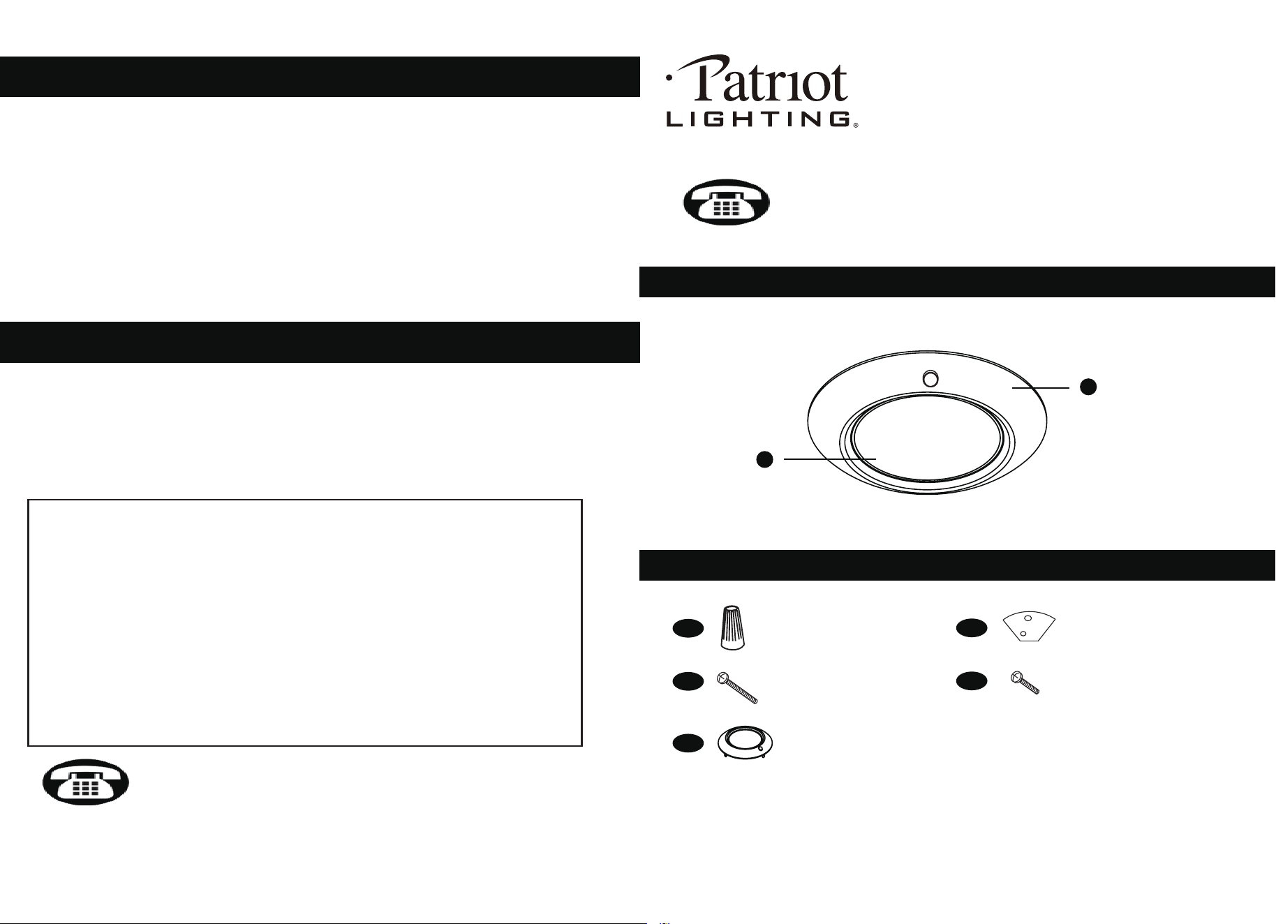
PACKAGE CONTENTS
HARDWARE CONTENTS Note: Hardware not shown actual size.
Wire Nut
x 3
Adaptor plate
x 2
AA
CC
DD
BB
A
B
4
CARE AND MAINTENANCE
TROUBLESHOOTING
1) The light does not come on at all:
a) Make sure the wall switch and circuit breaker are on.
b) Make sure the wiring is correct.
2) Fuse blows or circuit trips when light is turned on.
a) Check for crossed wires, ensure wiring is correct.
If unable to fix any of the above issues, please consult a certified electrician.
Questions, problems, missing parts?
Before returning to your retailer, call our customer service
at 1-800-267-4427 Monday – Friday 8:00 a.m. – 5:00 p.m. EST
5-YEAR LIMITED WARRANTY: If, during normal use, this PATRIOT LIGHTING
®
light fixture fails due to a defect in material and workmanship within five (5) years
from the date of purchase, simply bring this light fixture with your original sales
receipt back to your nearest MENARDS
®
retail store. At its discretion, PATRIOT
LIGHTING
®
agrees to have the lighting fixture replaced with the same or similar
PATRIOT LIGHTING
®
product free of charge, within the stated warranty period,
when returned by the original purchaser with original sales receipt. This warranty:
(1) excludes expendable parts including but not limited to light bulbs; (2) does not
cover damage that has resulted from abuse or misuse; and (3) does not cover any
losses, labor, injuries to persons/property or costs. This warranty does give you
specific legal rights and you may have other rights, which vary from state to state.
06-24
SKU Number: 351-7604
LED FLUSH MOUNT
Model Number: DL-4B-12DCFM-M
Mounting screw
x 2
Adaptor plate screw
x 2
• To clean, turn off and wipe with a damp, non-abrasive cloth.
• When cleaning, use only a soft brush or lint free cloth to avoid scratching the finish.
• Abrasive cleaning agents are not required and should be avoided to prevent damage
to the finish.
EE
Trim
x 2 (BN BK, 1pc each)
2
3
IMPORTANT SAFET
Y
INSTRUCTIONS
PREPARATION
Please read and understand this entire manual before attempting to assemble,
operate or install the product.
Please save this instruction manual.
WARNING
• Turn off electricity at main fuse box (or circuit breaker box) before beginning
installation by removing fuse (or switching off circuit breaker).
• Be careful not to damage or cut the wire insulation (covering) during fixture
installation. Do not permit wires to contact any surface having a sharp edge.
To do so may damage or cut the wire insulation, which could cause serious
injury or death from electric shock.
• This product must be installed in accordance with the applicable installation
code by a person familiar with the construction and operation of the product and
the hazards involved.
• Connect the ground wire (bare copper or green) from your fixture to the ground
wire (bare copper or green) or ground screw in the electrical box.
CAUTION
• All electrical connections must be in agreement with local codes, ordinances or
the national electric code (NEC). Contact your municipal building department to
learn about your local codes, permits and/or inspections.
• Risk of fire – most dwellings built before 1985 have supply wire rated for 140°F/60ºC.
Consult a qualified electrician before installation.
• Do not connect this fixture to an electrical system that does not provide a means for
equipment grounding. Never use a fixture in a two-wire system that is not grounded.
If you are not sure your lighting system has a grounding means, do not attempt to
install this fixture. Contact a qualified, licensed electrician for information with regards
to proper grounding methods as required by the local electrical code in your area.
• If a dimmer control switch is used with this fixture, obtain professional advice to
determine the correct type and electrical rating required.
Before beginning assembly, installation or operation of product, make sure all parts
are present. Compare parts with package contents list and diagram on previous page.
If any part is missing or damaged, do not attempt to assemble, install or operate the
product. Contact customer service for replacement parts.
Tools Required for Assembly (not included): Slotted Screwdriver, Phillips Screwdriver,
Pliers, Electrical Tape, Wire Cutters, Safety Glasses, Ladder, Wire Stripper
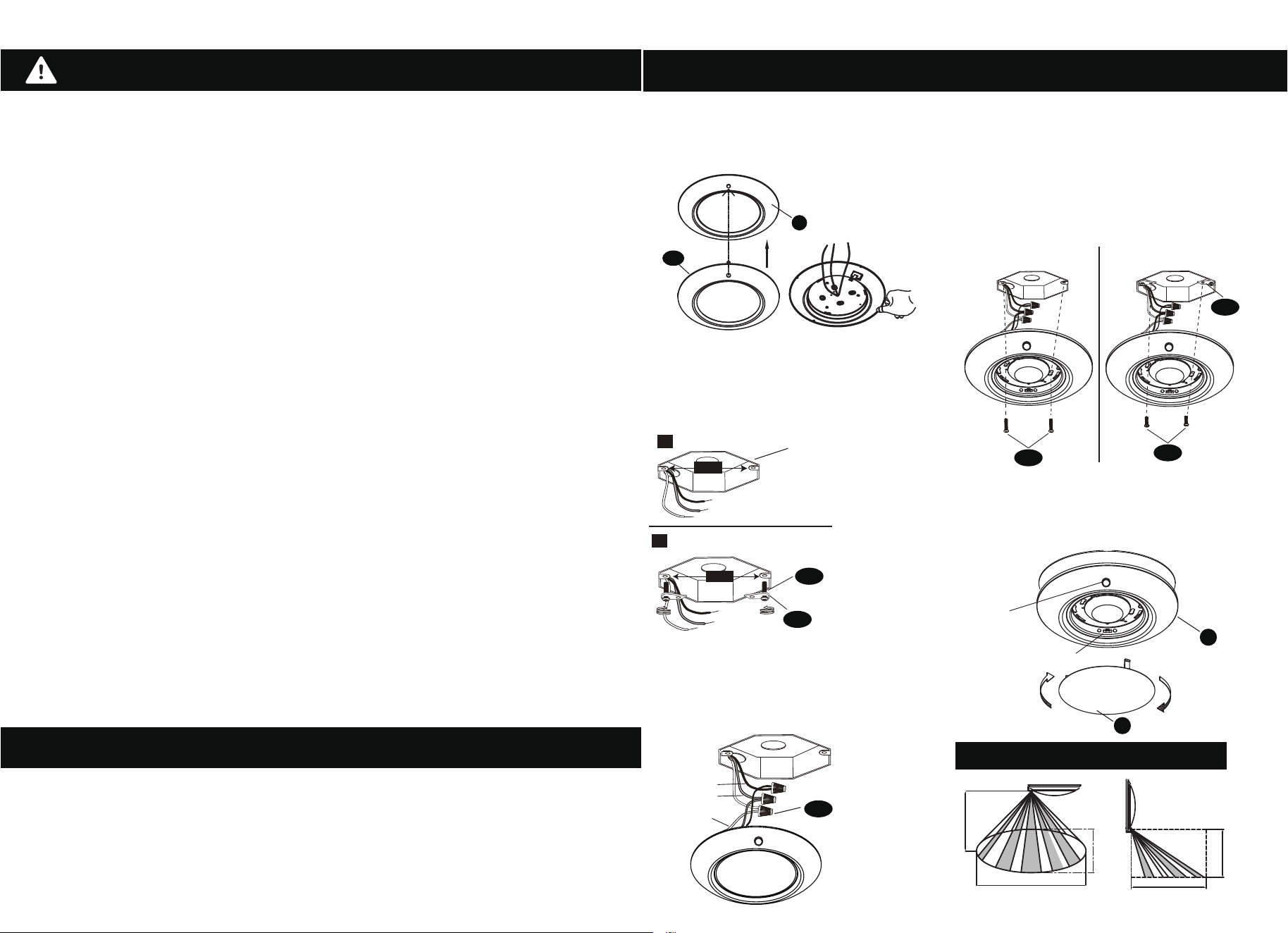
ASSEMBLY INSTRUCTIONS
A
B
Electrical
Box
For 2 3/4’’ electrical box
For 3 1/2’’ electrical box
A
2 ¾’’
2. Measure distance between mounting
screw as shown.
For 3 1/2’’ Box, attach adaptor plate (CC)
to electrical box using mounting
screws (BB) as shown in figure B.
3. Connect supply wires to wires on
fixture with wire nuts (AA).
Connect white to white, black to black,
and copper wire to copper wire as
grounding connection.
4. Twist the lens (B) counter-clockwise to
open the fixture.
For 2 3/4
’’ electrical box, raise the disk light
(A) to the electrical box. Tighten mounting
screws(BB) to firmly hold the disk light (A) in place.
For 3 1/2’’ electrical box, raise the disk light
(A) to the electrical box. Tighten adaptor
plate screws (DD) to firmly hold the disk light
(A) in place.
lens (B) on the disk light (A).
White
CCT swicth
3000K 4000K 5000K
Black
Ground
AA
CC
BB
BB
B
DD
ADAPTOR PLATE INSTALL
CC
3 ½’’
1. If need different color trim, attached the
trim(EE) to the fixture, and fold the four clips.
A
EE
motion sensor
16.4FT (5M)
7.9FT (2.4M)
16.4FT (5M)
MAX,19.7FT (6M)
5.9FT (1.8M)
Wall MountCeiling Mount
SENSOR DETECTION RANGE
Installation over standard electrical junction box.
5. Use the slide switch to choose a color temperature.
The options are 3000K, 4000K and 5000K.
6.
Complete the installation by twisting the