
RZT 17
OPERATOR’S MANUAL
IMPORTANT: READ SAFETY RULES AND INSTRUCTIONS CAREFULLY
CUB CADET LLC P.O. BOX 361131 CLEVELAND, OHIO 44136-0019 [www.cubcadet.com]
PRINTED IN U.S.A.
Warning:
This unit is equipped with an internal combustion engine and should not be used on or near any unimproved forest-
covered, brush-covered or grass-covered land unless the engine’s exhaust system is equipped with a spark arrester meeting
applicable local or state laws (if any). If a spark arrester is used, it should be maintained in effective working order by the operator.
In the State of California the above is required by law (Section 4442 of the California Public Resources Code). Other states may have
similar laws. Federal laws apply on federal lands. A spark arrester for the muffler is available through your nearest engine authorized
service dealer or contact the service department, P.O. Box 361131 Cleveland, Ohio 44136-0019.
FORM NO. 769-01124
TRACTOR
Model Number
(2/04)
w/42" Mower Deck
RZT SERIES

2
TRACTOR PREPARATION
Remove the upper crating material from the shipping
pallet, and cut any bands or tie straps securing the trac-
tor to the pallet. Use the lift handle to raise the deck to
its highest position; engage the transmission bypass
rods (Refer to SECTION 1, CONTROLS AND FEA-
TURES); and carefully roll the tractor off the shipping
palltet. Disengage the bypass rods.
CONNECT THE BATTERY
WARNING
Battery posts, terminals and related accessories
contain lead and lead compounds. Wash hands
after handling.
The tractor is shipped with an activated sealed battery,
with the positive battery cable factory connected. The
negative cable must be connected.
Note: Make sure the ignition switch is in the "OFF" po-
sition before attaching the battery cable.
1. Pull the protective cap off the negative terminal of
the battery, and remove the hex cap screw and nut
from the free end of the negative battery cable.
2. Connect the negative battery cable (heavy black)
to negative terminal (NEG) of the battery using the
hex cap screw and nut. Slide the black terminal
cover over the negative terminal of the battery.
REMOVE THE CHUTE STOP
• Locate the chute stop on the right side of the
mower, between discharge chute and cutting deck.
• While holding the discharge chute up, rotate the
chute stop clockwise and remove.
• Discard the chute stop.
Chute Stop
TABLE OF CONTENTS
TRACTOR PREPARATION .................................................................................................... 2
IMPORTANT SAFE OPERATION PRACTICES ..................................................................... 3
SAFETY DECALS AND LABELS ............................................................................................ 6
TO THE OWNER .................................................................................................................... 8
CALLING SERVICE INFORMATION ...................................................................................... 8
RECORDING MODEL AND SERIAL NUMBER INFORMATION ........................................... 8
SECTION 1: CONTROLS AND FEATURES ........................................................................... 9
SECTION 2: OPERATION .................................................................................................... 12
SECTION 3: ADJUSTMENTS ............................................................................................... 19
SECTION 4: MAINTENANCE ............................................................................................... 20
SECTION 5: MOWER DECK ................................................................................................ 25
SLOPE GAUGE .................................................................................................................... 29
ENGINE MANUAL ................................................................................................................. 31
WARRANTY ......................................................................................................... BACK PAGE
3
WARNING
• The engine exhaust, some of its constituents, and certain vehicle components contain or emit chemicals known
to the State of California to cause cancer, birth defects or other reproductive harm.
• This unit is equipped with an internal combustion engine and should not be used on or near any unimproved
forest-covered, brush-covered, or grass-covered land unless the engine’s exhaust system is equipped with a
spark arrester meeting applicable local or state laws (if any). If a spark arrester is used, it should be maintained
in effective working order by the operator.
• In the State of California, the above is required by law (Section 4442 of the California Public Resources Code).
Other States may have similar laws. Federal laws apply to federal lands. A spark arrester muffler is available
at your nearest engine authorized service center.
IMPORTANT
THIS SYMBOL POINTS OUT IMPORTANT SAFETY INSTRUCTIONS WHICH, IF NOT FOLLOWED,
COULD ENDANGER THE PERSONAL SAFETY AND/OR PROPERTY OF YOURSELF AND
OTHERS. READ AND FOLLOW ALL INSTRUCTIONS IN THIS MANUAL BEFORE ATTEMPTING
TO OPERATE YOUR UNIT. FAILURE TO COMPLY WITH THESE INSTRUCTIONS MAY RESULT
IN PERSONAL INJURY. WHEN YOU SEE THIS SYMBOL— HEED ITS WARNING.
SAFE OPERATION PRACTICES
Your lawn mower was built to be operated according to the rules for safe operation
in this manual. As with any type of power equipment, carelessness or error on the
part of the operator can result in injury. This lawn mower is capable of amputating
hands and feet or throwing objects. Failure to observe the following safety
instructions could result in serious injury or death.
I. GENERAL OPERATION
1. Read, understand and follow all instructions in the
manual and on the machine before starting. Keep
this manual in a safe place for future and regular
reference.
2. Only allow responsible individuals familiar with
the instructions to operate the machine. Know the
controls and how to stop the machine quickly.
3. Do not put hands or feet under the cutting deck or
near rotating parts.
4. Clear the area of objects such as rocks, toys,
wire, etc. which could be picked up and thrown by
the blades. A small object may have been
overlooked and could be accidentally thrown by
the mower in any direction and cause injury to
you or a bystander. To help avoid a thrown
objects injury, keep children, animals, bystanders
and helpers at least 75 feet from the mower while
it is in operation. Always wear safety glasses with
side shields or safety goggles during operation or
while performing an adjustment or repair, to
protect eyes from foreign objects. Stop the blades
when crossing gravel drives, walks or roads.
5. Be sure the area is clear of other people before
mowing. Stop machine if anyone enters the area.
6. Never carry passengers.
7. Disengage the blades before shifting into reverse
and backing up. Always look down and behind
before and while backing.
8. Be aware of the mower and attachment discharge
direction and do not point it at anyone. Do not
operate the mower without either the entire grass
catcher or the chute guard in place.
9. Slow down before turning. Operate the machine
smoothly. Avoid erratic operation and excessive
speed.
10. Never leave a running machine unattended.
Always turn off the blades, place the transmission
in neutral, set the parking brake, stop the engine
and remove key before dismounting.
11. Turn off blades when not mowing.
12. Stop the engine and wait until the blades come to
a complete stop before (a) removing the grass
catcher or unclogging chute, or (b) making any
repairs, adjusting or removing any grass or debris.
DANGER

4
13. Mow only in daylight or good artificial light.
14. Do not operate the machine while under the
influence of alcohol or drugs.
15. Watch for traffic when operating near or crossing
roadways.
16. Use extra care when loading or unloading the
machine into a trailer or truck. This unit should not
be driven up or down a ramp onto a trailer or truck
under power, because the unit could tip over
causing serious personal injury. The unit must be
pushed manually on a ramp to load or unload
properly.
17. Never make a cutting height adjustment while the
engine is running if the operator must dismount to
do so.
18. Wear sturdy, rough-soled work shoes and close-
fitting slacks and shirts. Do not wear loose fitting
clothes or jewelry. They can be caught in moving
parts. Never operate a unit in bare feet, sandals
or sneakers.
19. Check overhead clearance carefully before driving
under power lines, wires, bridges or low hanging
tree branches, before entering or leaving
buildings, or in any other situation where the
operator may be struck or pulled from the unit,
which could result in serious injury.
20. Disengage all attachment clutches, set the
parking brake in the on position, and put the lap
bars to the neutral or out position before
attempting to start the engine.
21. Your mower is designed to cut normal residential
grass of a height no more than 10”. Do not
attempt to mow through unusually tall, dry grass
(e.g. pasture) or piles of dry leaves. Debris may
build up on the mower deck or contact the engine
exhaust presenting a potential fire hazard.
22. Use only accessories approved for this machine
by Cub Cadet. Read, understand and follow all
instructions provided with the approved
accessory.
II. SLOPE OPERATION
Slopes are a major factor related to loss of control and
tip-over accidents, which can result in severe injury or
death. All slopes require extra caution. If you cannot
back up the slope or if you feel uneasy on it, do not
mow it.
For your safety, use the slope gauge included as part
of this manual to measure slopes before operating this
unit on a sloped or hilly area. If the slope is greater
than 15° as shown on the slope gauge, do not operate
this unit on that area or serious injury could result.
DO:
Mow across slopes, not up and down.
Remove obstacles such as rocks, limbs, etc.
Watch for holes, ruts or bumps. Uneven terrain could
overturn the machine. Tall grass can hide obstacles.
Use slow speed. Choose a low enough speed so that
you will not have to stop while on the slope.
Follow the manufacturer’s recommendations for coun-
terweights with attachments to improve stability.
Use extra care with grass catchers or other attach-
ments. These can change the stability of the machine.
Keep all movement on the slopes slow and gradual.
Do not make sudden changes in speed or direction.
Rapid acceleration or deceleration could cause the
front of the machine to lift and rapidly flip over back-
wards, which could cause serious injury.
Avoid starting or stopping on a slope. If the tires lose
traction, disengage the blades and proceed slowly
straight down the slope.
DO NOT:
Do not turn on slopes unless necessary; then, turn
slowly and gradually downhill, if possible.
Do not mow near drop-offs, ditches or embankments.
The mower could suddenly turn over if a wheel is over
the edge of a cliff or ditch, or if an edge caves in.
Do not mow on wet grass. Reduced traction could
cause sliding.
Do not try to stabilize the machine by putting your foot
on the ground.
Do not use the grass catcher on steep slopes.
III. CHILDREN
Tragic accidents can occur if the operator is not alert
to the presence of children. Children are often
attracted to the machine and the mowing activity.
Never assume that children will remain where you
last saw them.
1. Keep children out of the mowing area and in
watchful care of an adult other than the operator.
2. Be alert and turn the machine off if children enter
the area.
3. Before and when backing up, look behind and
down for small children.
4. Never carry children, even with the blades off.
They may fall off and be seriously injured or may
interfere with safe machine operation.

5
5. Never allow children under 14 years old to
operate the machine. Children 14 years and over
should only operate the machine under close
parental supervision and proper instruction.
6. Use extra care when approaching blind corners,
shrubs, trees or other objects that may obscure
your vision of a child or other hazard.
7. Remove the key when the machine is left
unattended to prevent unauthorized operation.
IV. SERVICE
1. Use extreme care in handling gasoline and other
fuels. They are extremely flammable and the
vapors are explosive.
a. Use only an approved container.
b. Never remove fuel cap or add fuel with the en-
gine running. Allow the engine to cool at least
two minutes before refueling.
c. Replace the fuel cap securely and wipe off any
spilled fuel before starting the engine as it may
cause a fire or explosion.
d. Extinguish all cigarettes, cigars, pipes and oth-
er sources of ignition.
e. Never refuel the machine indoors because fuel
vapors will accumulate in the area.
f. Never store the fuel container or machine
inside where there is an open flame or spark,
such as a gas hot water heater, space heater
or furnace.
2. Never run a machine inside a closed area.
3. To reduce fire hazard, keep the machine free of
grass, leaves or other debris build-up. Clean up
oil or fuel spillage. Allow the machine to cool at
least 5 minutes before storing.
4. Before cleaning, repairing or inspecting, make
certain the blade and all moving parts have
stopped. Disconnect the spark plug wire, and
keep the wire away from the spark plug to prevent
accidental starting.
5. Check the blade and engine mounting bolts at fre-
quent intervals for proper tightness. Also visually
inspect blades for damage (e.g., excessive wear,
bent, cracked). Replace with blades which meet
original equipment specifications.
6. Keep all nuts, bolts and screws tight to be sure
the equipment is in safe working condition.
7. Never tamper with safety devices. Check their
proper operation regularly. Use all guards as
instructed in this manual.
8. After striking a foreign object, stop the engine,
remove the wire from the spark plug and
thoroughly inspect the mower for any damage.
Repair the damage before restarting and
operating the mower.
9. Grass catcher components are subject to wear,
damage and deterioration, which could expose
moving parts or allow objects to be thrown. For
your safety protection, frequently check the
components and replace with manufacturer’s
recommended parts when necessary.
10. Mower blades are sharp and can cut. Wrap the
blades or wear gloves, and use extra caution
when servicing blades.
11. Check the park brake operation frequently. Adjust
and service as required.
12. Muffler, engine and belt guards become hot
during operation and can cause a burn. Allow to
cool down before touching.
13. Do not change the engine governor settings or
overspeed the engine. Excessive engine speeds
are dangerous.
14. Observe proper disposal laws and regulations.
Improper disposal of fluids and materials can
harm the environment and the ecology.
a. Prior to disposal, contact your local
Environmental Protection Agency to
determine the proper method for disposing of
the waste. Recycling centers are established
to properly dispose of materials in an
environmentally safe fashion.
b. Use proper containers when draining fluids.
Do not use food or beverage containers that
may mislead someone into drinking from
them. Properly dispose of the containers im-
mediately following the draining of fluids.
c. DO NOT pour oil or other fluids into the
ground, down a drain or into a stream, pond,
lake, or other body of water. Observe Environ-
mental Protection Agency regulations when
disposing of oil, fuel, coolant, brake fluid, fil-
ters, batteries, tires and other harmful waste.
15. We do not recommend the use of a pressure
washer or garden hose to clean your unit. They
may cause damage to electrical components;
spindles; pulleys; bearings; or the engine. The
use of water will result in shortened life and
reduce serviceability.
WARNING - YOUR RESPONSIBILITY: Restrict the use of this power machine to persons who
read, understand and follow the warnings and instructions in this manual and on the machine.
6
SAFETY DECALS AND LABELS
Keep product safety graphics (decals) clean. Replace any safety graphic that is damaged, destroyed, missing, paint-
ed over or can no longer be read. Replacement safety graphics are available through your dealer.
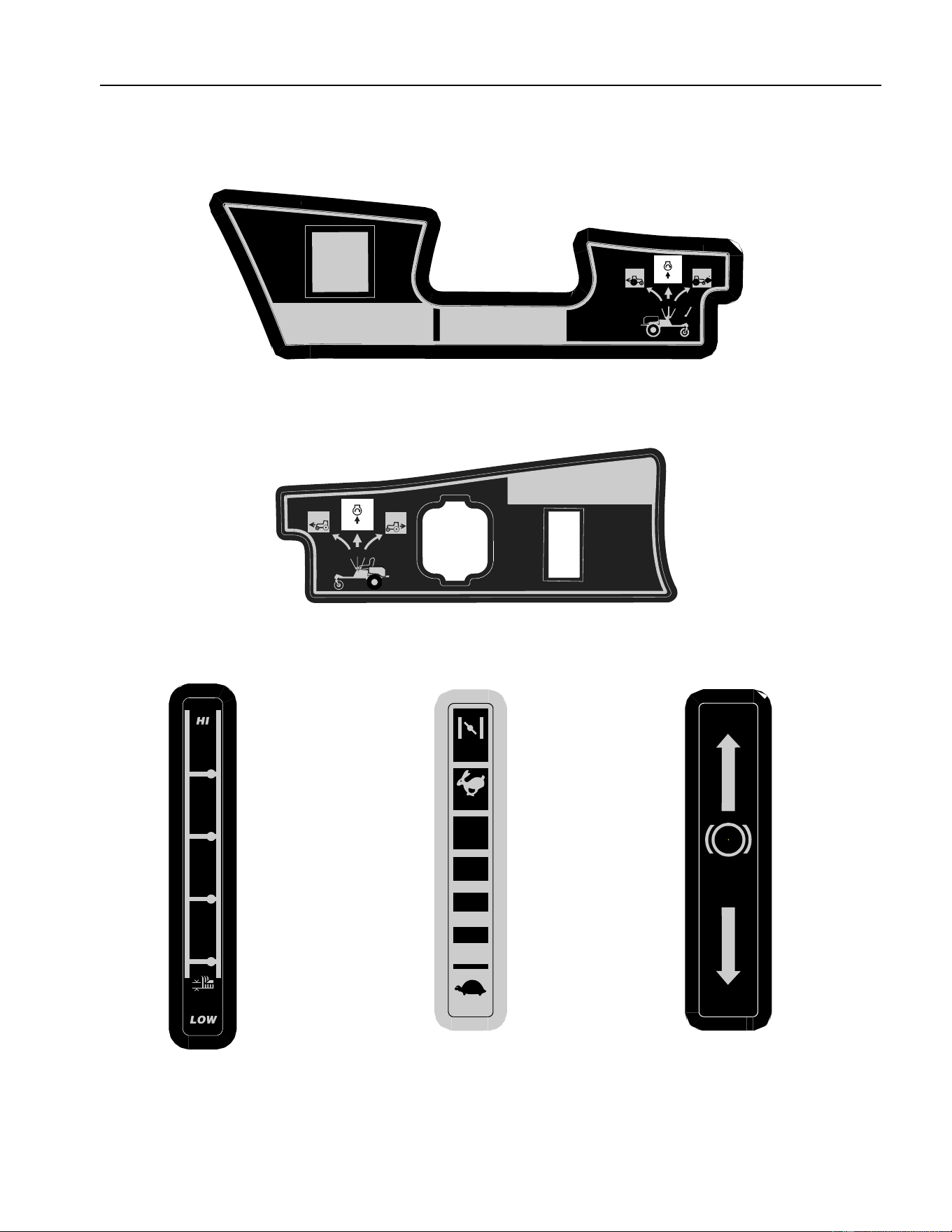
GENERAL OPERATING INSTRUCTIONS
– LOCATED ON RIGHT CONSOLE
ASIDE OPERATOR’S SEAT
CUTTING
HEIGHT
•
PTO
Automatically Disengages When Both Lap
Bars Are Moved Too Far Into Reverse
.
•
PTO Automatically Reengages When Levers Are
Returned To The Neutral Or Forward Positions.
NOTICE
START
NEUTRAL
FORWARD
REVERSE
FOR FIRST-TIME OPERATORS
•
Start Off In A Flat, Open Area.
•
Keep Bystanders Away.
•
Set Throttle At A Low Speed.
•
Practice Maneuvering, (Fo rward, Reverse,
Left, Right) Wi thout Deck Engaged.
STARTING INSTRUCTIONS
•
To START, PARK BRAKE must be set.
•
P.T.O. switch in OFF (down) position.
•
Lap bars in NEUTRAL and outward positions.
•
Throttle set properly, CHOKE position if "cold".
•
Turn key to ON, then START, release when engine runs.
START
NEUTRAL
FORWARD
REVERSE
ON
OFF
PARK
BRAKE
P
FAST
SLOW
CHOKE
GENERAL SAFETY INSTRUCTIONS
– LOCATED ON LEFT CONSOLE
ASIDE OPERATOR’S SEAT
DECK HEIGHT INDICATOR
– LOCATED ON RIGHT SIDE
OF SEAT BOX FRAME
THROTTLE CONTROL
INDICATOR – LOCATED ON
LEFT CONSOLE
PARK BRAKE INDICATOR
– LOCATED ON LEFT SIDE
OF SEAT BOX FRAME
7
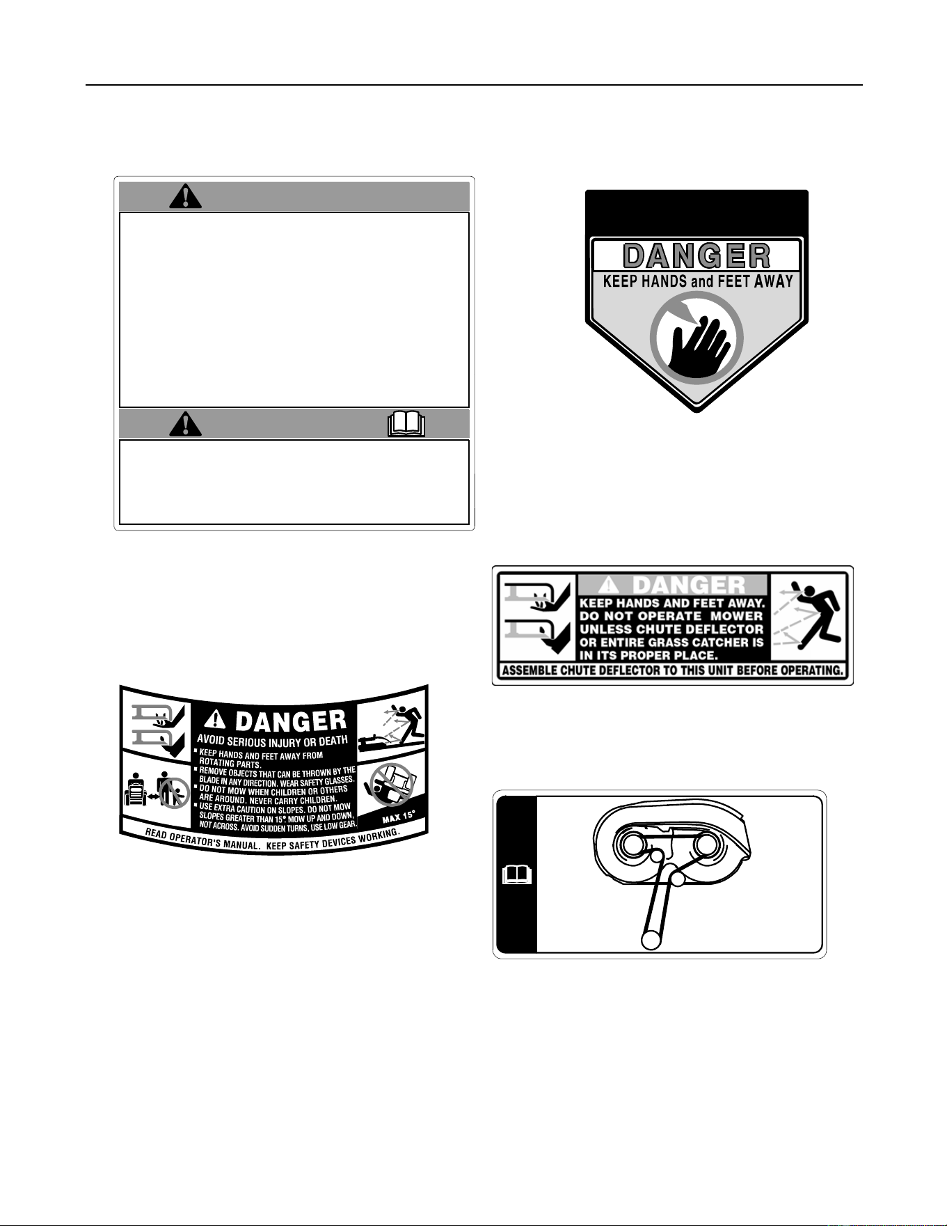
GENERAL SAFETY INSTRUCTIONS
WARNING – LOCATED IN CENTER
OF SEAT BOX FRAME
SAFETY DECALS AND LABELS
HANDS AND FEET SAFETY GRAPHIC–
LOCATED ON DEFLECTOR CHUTE
TO
REDUCE
TH E
RISK
OF
INJURY ,
DO
NOT
OPERATE
UNLESS
DISCHARGE
CO VER
OR
GRASS
CATCHER
IS
IN
ITS
PR O PER
PL ACE.
IF
DAMAGED,
REPLACE
IMMEDIATELY.
DEFLECTOR and SAFETY GRAPHIC –
LOCATED ON RIGHT SIDE OF DECK
SAFETY GRAPHIC – LOCATED ON
LEFT SIDE OF MOWER DECK
WARNING
WARNING
• Read The Operator's Manual.
• Go Across Slopes, Not Up And Down.
•
If Machine Stops Going Uphill, Stop Blade And Back Down Slowly.
• Avoid Sudden Turns.
• Do Not Mow When Children Or Others Are Around.
• Never Carry Children Even With Blades Off.
• Look Down And Behind Before And While Backing.
•
Keep Safety Devices (Guards, Shields, Switches, Etc.) In Place And Working.
• Remove Objects That Could Be Thrown By The Blade.
•
Do Not Operate Unit Where It Could Slip Or Tip.
• Know Location And Function Of All Controls.
•
Be Sure Blades And Engine Are Stopped Before Placing Hands Or Feet Near Blades.
•
Before Leaving Operator Position, Disengage Blades, Place In Neutral,
Engage Parking Brake, Shut Off And Remove Key.
•
When Using The Optional Grass Bagging Attachment, The Front Counter
Weight Included With Bagger Must Be Installed.
AVOID SERIOUS INJURY OR DEATH
• Do not add fuel while the engine is hot or running.
•
Stop engine, disconnect spark plug before adjusting or servicing.
• Before leaving operator's position:
•
DISENGAGE IMPLEMENT DRIVE.
•
Place speed controls in neutral and set parking brake.
•
Wait for all movement to stop.
• Do not allow operation by untrained personnel.
INFORMATION GRAPHIC – BELT
ROUTING LOCATED ON
LEFT SIDE OF MOWER DECK

8
TO THE OWNER
This Operator’s Manual is an important part of your new tractor. The information contained in this manual has been
prepared in detail to help you better understand the features, correct operation, adjustments, and maintenance of
your tractor. The performance and dependability of this tractor rely greatly on the manner in which it is operated and
maintained. Therefore, it is recommended that all operators of the tractor carefully read this manual and fully under-
stand its operation. Also keep the manual available for reference to ensure proper operation, and that maintenance
procedures are performed as scheduled to assure the tractor’s optimal mechanical condition.
NOTE: All references to LEFT, RIGHT, FRONT, and REAR, unless specifically stated otherwise, indicate that rela-
tive position on the tractor when facing forward while seated in the operator’s seat.
CAUTION: DO NOT tow your Model RZT 17 tractor. Towing may damage the transmissions. Place the tractor on a
LEVEL SURFACE before pulling the transmission bypass rods to the engaged position (transmission disengaged).
Your local authorized Cub Cadet dealer is interested in the performance you receive from your tractor, and with the
maintenance needed to ensure the satisfactory operation of your tractor. The dealer has trained service personnel
familiar with the latest servicing information, is equipped with the latest tools, and has a complete line of genuine
Cub Cadet service parts which assure proper fit and high quality.
CALLING SERVICE INFORMATION
The engine manufacturer is responsible for all engine-related issues with regards to performance, power-rating, and
specifications.
If you have difficulties with the tractor and/or equipment; have any questions regarding the operation or maintenance
of this equipment; or desire additional information not found in this manual, contact your nearest authorized Cub
Cadet dealer. If you need assistance in locating a dealer in your area, contact the Customer Dealer Referral Line by
calling:
1-877-282-8684
Or you may contact Cub Cadet via the internet by logging on to our Web Site at:
www.cubcadet.com
To obtain top performance and assure economical operation, the tractor should be inspected by your authorized
dealer periodically or at least once a year, depending on its hours of use. Before calling your dealer, make sure that
you have your model number(s) and manufacturing date available for the dealer.
RECORDING MODEL AND SERIAL NUMBER INFORMATION
Product identification plates are provided for major components of your tractor. The numbers on these plates are
important if your tractor should require dealer service, or if you need additional information on your tractor. Prior to
using your tractor for the first time, record the numbers from the identification plates in the appropriate spaces pro-
vided below.
The chassis model plate, showing the factory model number and Mfg. Date (See Figure 1) can be found either on
the underside of the seat mounting base or on the right frame rail near the right front tire.
The engine information is stamped in the upper surface of the of the valve cover (See Figure 2).
Model Factory Model No. Mfg. Date
Delivery Date Engine Model/Type No. Engine Code No.
Figure 1 Figure 2
www.cubcadet.com
CUB CADET LLC
P. O. BOX
361131
CLEVELAND, OH 44136
DEALER LOCATOR PHONE NUMBER:
877-282-8684
Model Number Mfg. Date
XXXXXXXXXXX XXXXXXXXXX
VALVE
COVER
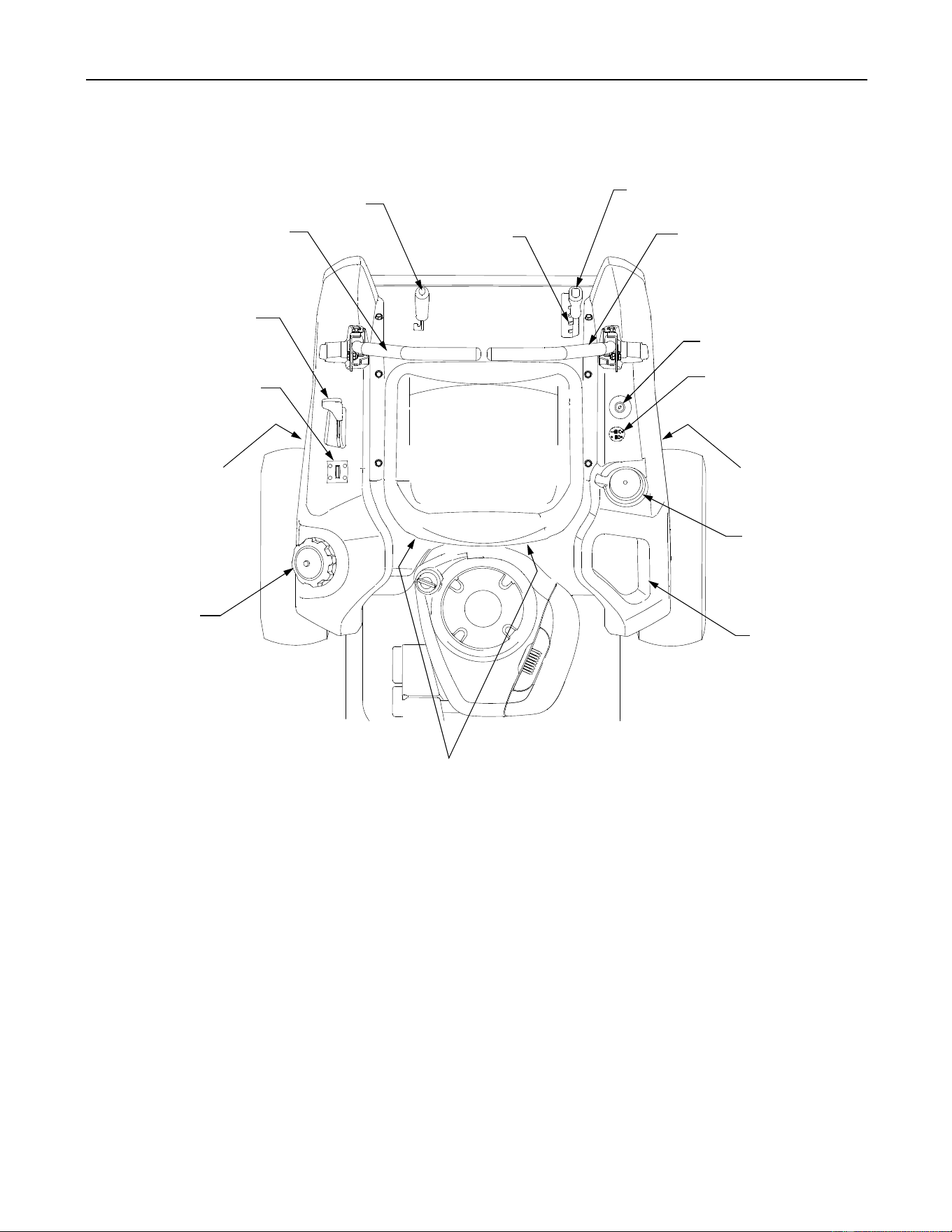
9
SECTION 1: CONTROLS AND FEATURES
Figure 3
A
B
C
D
E
F
G
H
J
K
L
M
C
N
F
N.
M.
L.
K.
J.
A.
B.
C.
D.
E.
F.
H.Deck Height Index
RH and LH Drive Control Levers
Deck Lift Handle
Ignition Switch
PTO Switch
Transmission Bypass Rod (Not Shown)
G. Cup Holder
Storage Tray
Seat Adjustment Wing Knobs (Not Shown)
Fuel Tank Cap
Hour Meter /Indicator Panel
Throttle Control
Parking Brake Engagement Lever

10
NOTE: References to LEFT, RIGHT, FRONT, and
REAR indicate that position on the tractor when
facing forward while seated in the operator’s seat.
A. Deck Height Index
The deck height index consists of six index notches
located on the front/right of the seat box frame. Each
notch corresponds to a 1/2 inch change in the deck
height position ranging from 1-1/2 inches at the low-
est notch to 4 inches at the highest notch.
B. Deck Lift Handle
The deck lift handle is located on the front/right of the
seat box frame, and is used to raise and lower the
mower deck.
Pull the handle to the left out of the index notch and
push downward to lower the deck, or pull upward to
raise the deck. When the desired height is attained,
move the lift handle to the right until fully in the index
notch.
C. RH and LH Drive Control Levers
The RH and LH control levers are located to each
side of the operator’s seat. These hinged levers open
out to the side in the neutral position to permit the
operator to be seated or to leave the tractor seat. The
levers must be fully opened out in the neutral position
to start the tractor engine.
Each lever controls the respective RH or LH transmis-
sion. Consequently, these levers control all of the
movements of the tractor. Driving and steering utiliz-
ing these control levers is quite different from
conventional tractors, and will take some practice to
master. Refer to SECTION 2: OPERATION for
instructions on using the control levers.
D. Ignition Switch
The ignition switch is located on the RH console to
the right of the operator’s seat.
The ignition switch has three positions as follow:
Figure 4
OFF - The engine and electrical system is turned off.
ON - The tractor electrical system is energized.
START- The starter motor will turn over the engine.
Release the key immediately when the
engine starts
NOTE: To prevent accidental starting and/or battery
discharge, remove the key from the ignition switch
when the tractor is not in use.
E. Power Take-Off (PTO) Switch
The PTO switch is located on the RH console to the
right of the operator’s seat.
Figure 5
The PTO switch operates the electric PTO clutch
mounted on the bottom of the engine crankshaft. Pull
the switch knob upward to engage the PTO clutch, or
push the knob downward to disengage the clutch.
The PTO switch must be in the "disengaged" position
when starting the engine.
F. Transmission Bypass Rods (Not Shown)
The transmission bypass rods (one for each the RH
and LH transmission) are located beneath the frame
platform, just inside each rear wheel.
When engaged, the two rods open a bypass within the
hydrostatic transmissions, which allows the tractor to
be pushed short distances by hand. Refer to
SECTION 2: OPERATION for instructions on using
the bypass feature.
WARNING: Never tow your tractor.
Towing the tractor with the rear wheels
on the ground may cause severe damage
to the transmissions.
G. Cup Holder
The cup holder is located toward the rear of the RH
console to the right of the operator’s seat.
H. Storage Tray
The storage tray is located at the rear of the RH
console.
ON
OFF
START
STOP
11
J. Seat Adjustment Wing Knobs (Not Shown)
The seat adjustment wing knobs are located
underneath the seat hinge bracket. The wing knobs
allow for tool free adjustment of the fore and aft
position of the operator’s seat. Refer to SECTION 3:
ADJUSTMENTS for instructions on adjusting the seat
position.
K. Fuel Tank Cap
The fuel tank cap is located at the rear of the LH
console. Turn the cap counterclockwise to unscrew
and remove from the fuel tank. Always re-install the
fuel cap tightly onto the fuel tank after removing.
WARNING: Never fill the fuel tank when
the engine is running. If the engine is hot
from recently running, allow to cool for
several minutes before refueling. Highly
flammable gasoline could splash onto
the engine and cause a fire.
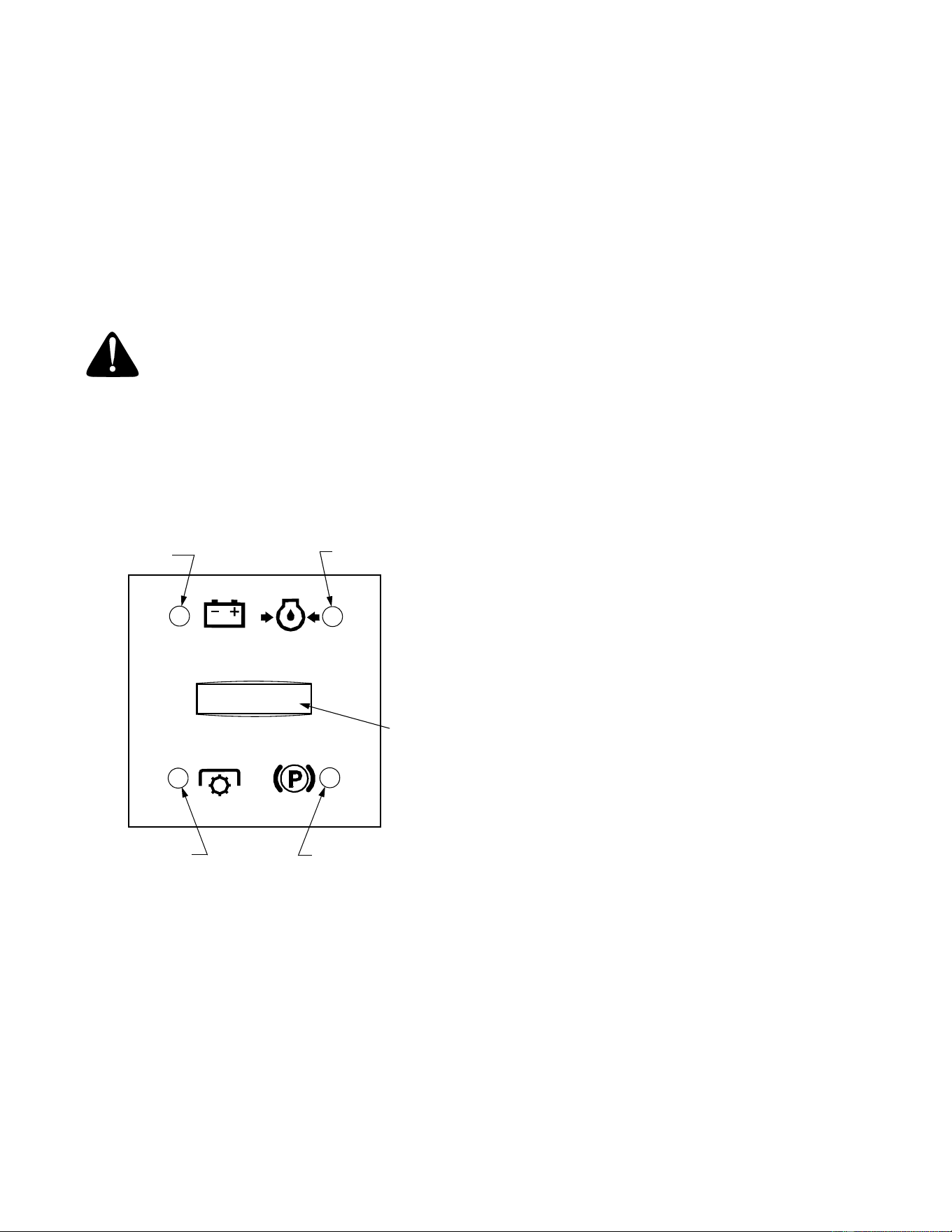
L. Hour Meter/Indicator Panel
The hour meter/indicator panel is located on the LH
console to the left of the operator’s seat.
Figure 6
Hour Meter Feature
The purpose of the hour meter is to record the hours
(tenths of an hour-right most digit) that the tractor has
been operated.
• The hour meter is activated whenever the ignition
switch is turned to the "ON" position. Because of
this, a record of the actual hours of operation
should be kept to assure all maintenance
procedures are completed according to the
schedule in this manual.
• When key is turned to the "ON" position, the
battery indicator light briefly illuminates and the
battery voltage is briefly displayed. The display
then changes to the accumulated hours.
Indicator Panel Feature
Battery Indicator (Refer to Figure 6)
• Illuminates and the battery voltage is displayed
briefly when the ignition switch it turned to the
"ON" position.
• Illuminates to indicate the battery voltage has
dropped below 11.5 (+0.5/-1.0) volts. The battery
voltage is also displayed on the hour meter. If this
indicator and display come on during operation,
check the battery and charging system for possi-
ble causes and/or contact your Cub Cadet dealer.
Oil Pressure Indicator (Refer to Figure 6)
• This warning lamp indicates low engine oil
pressure. If the indicator comes on while the
engine is running, stop the engine immediately
and check for possible causes. Do not run the
engine while this indicator is illuminated. Contact
your Cub Cadet dealer to have the tractor and
engine inspected.
NOTE: The oil pressure indicator may illuminate
when the ignition switch is in the ON position, but
should turn off when the engine is started.
PTO Engaged Indicator (Refer to Figure 6)
• This indicator illuminates any time the PTO switch
is pulled upward in the "ENGAGED" position and
the ignition switch is in the "ON" or "START"
position. Check this indicator if the engine will not
crank with the ignition switch in the "START"
position; then move the PTO switch to the
"DISENGAGED" position if necessary.
Parking Brake Engaged Indicator (Refer to Figure 6)
• This indicator illuminates any time the parking
brake is in the "ENGAGED" position and the igni-
tion switch is in the "ON" or "START" position.
When starting the engine, the parking brake must
be engaged and this indicator should be
illuminated.
Battery
Oil Pressure
PTO Engaged
Parking Brake
Engaged Indicator
Indicator
Indicator
Indicator
Hour
Meter

12
M. Throttle Control
The throttle control is located on the LH console to
the left of the operator’s seat. When set in a given
position, a uniform engine speed will be maintained.
Figure 7
• Push the control handle forward to increase the
engine speed. The tractor is designed to operate
with the control handle in the fast position (full
throttle) when the tractor is driven and the mower
deck is engaged.
• Pull the control handle rearward to decrease the
engine speed.
• When starting the engine, push the control
handle fully forward into the "CHOKE" position.
See Figure 7. After starting and warming the
engine, move the control handle rearward until
you feel it move past the choke detent.
N. Parking Brake Engagement Lever
The parking brake engagement lever is located on
the front/left of the seat box frame, and is used to
engage the parking brake.
• Pull the lever fully upward and to the left and
lower into the "J" slot to engage the parking
brake.
• Pull the lever up out of the "J" slot and to the
right; then lower completely to disengage the
parking brake.
IMPORTANT: If the LH and RH drive control levers
are not fully opened out in the neutral position when
engaging the parking brake, the engine will stop. The
parking brake must be placed in the engaged position
when starting the tractor engine.
SECTION 2: OPERATION
GENERAL SAFETY
• RECEIVE INSTRUCTION - Read the operator’s
manual. Learn to operate this machine SAFELY.
Don’t risk INJURY or DEATH. Allow only those
who have become competent in its usage to
operate this tractor .
• Familiarize yourself with the operations of all the
instruments and controls.
• Before starting the engine or beginning operation,
be familiar with the controls. The operator should
be in the operator’s seat. The PTO switch must
be in the disengaged position, the parking brake
engaged, and the RH and LH drive control levers
moved fully outward in the neutral position.
• Keep all shields in place. Keep away from moving
parts.
• NO RIDERS! Keep all people and pets a safe
distance away. Look behind to both sides before
backing up.
• DO NOT direct the mower discharge at people.
• Avoid slopes where possible. Never operate on
slopes greater than 15°. Slopes with a greater
incline present dangerous operating conditions.
Tractors can be rolled over.
• Before leaving the operator’s seat: Shut off the
PTO, move the RH and LH drive control levers
fully outward in the neutral position, engage the
parking brake, shut off the engine and remove
the ignition key. Wait for all movement to stop
before servicing or cleaning.
• Operate the drive control levers smoothly and
avoid any sudden movements of the levers
when starting and stopping. Keep a firm grip on
the control levers; do not allow the levers to
return to neutral on their own.
• Be careful when operating near roadways. Stop
the tractor motion and wait for vehicles to pass
before operating along the road.
• Do not operate the tractor with the mower deck
removed. Removal of the deck will change the
balance of the tractor, and could contribute to a
tractor rollover.
• Avoid operation or use extreme care if the
traction surface is, unstable, or slippery.
• Slow down before turning and come to a
complete stop before any zero turn maneuver.
• Do not stop the tractor or park the tractor over
combustible materials such as dry grass, leaves,
debris, etc.
• Do not fill the fuel tank when the engine is
running or while the engine is hot. Allow the
engine several minutes to cool before refueling.
Tighten the fuel cap securely.
This symbol indicates the
This symbol indicates the
fast position.
slow position.
CHOKE
This symbol indicates the
choke position.
13
BEFORE OPERATING YOUR TRACTOR
• Before you operate the tractor, study this manual
carefully. It has been prepared to help you
operate and maintain your tractor efficiently.
• Familiarize yourself with the operations of all the
instruments and controls.
• This engine is certified to operate on unleaded
gasoline. For best results, fill the fuel tank with
only clean, fresh, unleaded gasoline with a pump
sticker octane rating of 85 or higher. Unleaded
gasoline is recommended because it leaves less
combustion chamber deposits.
Some fuels are gasoline blended with alcohols or
ethers. Excessive amounts of the these blends
can damage the fuel system or cause engine
performance problems. If undesirable operating
symptoms occur, use gasoline with a lower
percentage of alcohol or ether. Do not use
gasoline that contains Methanol.
• Check the engine oil level.
• Clean the air cleaner element if necessary.
• Check the tire inflation pressures.
• Adjust the seat for operator’s maximum comfort,
visibility and for maintaining complete control of
the tractor.
SAFETY INTERLOCK SYSTEM
This tractor is equipped with a safety interlock system
for the protection of the operator. If the interlock
system should ever malfunction, do not operate the
tractor. Contact your authorized Cub Cadet Dealer.
• The safety interlock system prevents the engine
from cranking or starting unless the RH and LH
drive control levers are moved fully outward in the
neutral position, the parking brake is engaged,
and the PTO is disengaged.
• To avoid sudden movement when disengaging
the parking brake, the safety interlock system will
shut off the engine if the RH and/or LH drive
control levers are moved to a position other than
the fully out in neutral position when the parking
brake is engaged
• The safety interlock system will shut off the
engine if the operator leaves the seat before
engaging the parking brake.
• The safety interlock system will shut off the
engine if the operator leaves the seat with the
PTO engaged, regardless of whether the parking
brake is engaged.
NOTE: The PTO switch must be moved to the
“OFF” position to restart the engine.
• The safety interlock system will shut off the PTO
and the mower blades will stop if both drive con-
trol levers are moved into the reverse position.
The PTO will re-engage when one or both of the
levers are moved back to the neutral or forward
position.
STARTING THE ENGINE
WARNING: For personal safety, the
operator must be sitting in the tractor
seat when starting the engine.
WARNING: This unit is equipped with a
safety interlock system designed for the
protection of the operator. Do not oper-
ate the tractor if any part of the interlock
system is malfunctioning. Periodically
check the functions of the interlock sys-
tem for proper operation.
• Move the RH and LH drive control levers fully
outward in the neutral position. Refer to Figure 8.
• Operator must be sitting in the tractor seat.
• Engage the parking brake. Refer to Figure 8.
• Make certain the PTO switch is in the disen-
gaged (down) position. Refer to Figure 8.
• Move the throttle control lever fully forward into
the "CHOKE" position. NOTE: If the engine is
warmed up, it may not be necessary to place the
throttle control in the choke position.
Figure 8
• Turn the ignition key clockwise to the “START”
position and release it as soon as the engine
starts; however, do not crank the engine continu-
ously for more than 5 seconds at a time. If the
engine does not start within this time, turn the key
to “OFF” and wait a minute to allow the engine’s
starter motor to cool. Try again after waiting. If
after a few attempts the engine fails to start, do
LH Control Lever
Out in Neutral
Parking Brake
RH Control Lever
Out in Neutral
Engaged
Throttle Control
Forward in Choke
PTO Switch in Down
(Disengaged) Position

14
not keep trying to start it with the choke closed as
this will cause flooding and make starting more
difficult.
• As the engine warms up, gradually pull the throt-
tle control lever rearward past the choke detent
position. Do not use the choke to enrich the fuel
mixture, except as necessary to start the engine.
• Allow the engine to run for a few minutes at mid
throttle before putting the engine under load.
• Observe the hour meter/indicator panel. If the
battery indicator light or oil pressure light come
on, immediately stop the engine. Have the tractor
inspected by your Cub Cadet dealer.
COLD WEATHER STARTING
Be sure to use the proper oil for the expected
temperatures (Check the table in the engine section
at the back of this manual). Follow the normal engine
starting instructions above. However, allow the
engine ample time to warm up before putting the
tractor under load.
USING JUMPER CABLES TO START ENGINE
WARNING: Batteries contain sulfuric acid
and produce explosive gasses. Make
certain the area is well ventilated, wear
gloves and eye protection, and avoid
sparks or flames near the battery.
If the battery charge is not sufficient to crank the
engine, recharge the battery. If a battery charger is
unavailable and the tractor must be started, the aid of
a booster battery will be necessary. Connect the
booster battery as follows:
• Connect the end of one cable to the disabled
tractor battery’s positive terminal; then connect
the other end of that cable to the booster
battery’s positive terminal.
• Connect one end of the other cable to the booster
battery’s negative terminal.
• Connect the other end of that cable to the frame
of the disabled tractor, as far from the battery as
possible.
• Start the disabled tractor following the normal
starting instructions previously provided; then
disconnect the jumper cables in the exact reverse
order of their connection.
• Have the tractor’s electrical system checked and
repaired as soon as possible to eliminate the
need for jump starting.
STOPPING THE ENGINE
• Place the PTO switch in the “OFF” position.
• Engage the parking brake.
• Move the RH and LH drive control levers fully
outward in the neutral position.
• Place the throttle control lever to the fast (high
idle) position.
• Turn the ignition key to the “OFF” position and
remove the key from the ignition switch.
NOTE:
Always remove the key from the ignition
switch to prevent accidental starting or battery
discharge if the equipment is left unattended.
PRACTICE OPERATION (INITIAL USE)
Operating a zero-turn tractor is not like operating a
conventional type riding tractor. Although and be-
cause a zero-turn tractor is more maneuverable, get-
ting used to operating the control levers takes some
practice.
We strongly recommend that you locate a reason-
ably large, level and open "practice area" where there
are no obstructions, pedestrians, or animals. You
should practice operating the tractor for a minimum of
30 minutes.
Carefully move (or have moved) the tractor to the
practice area. When performing the practice session,
it not necessary operate with the PTO engaged.
While practicing operate the tractor at approximately
1/2 throttle and at less than full speed in both forward
and reverse.
Carefully practice maneuvering the tractor using the
instructions in the following section "Driving the Trac-
tor." Practice until you are confident that you can
safely operate the tractor.
DRIVING THE TRACTOR
WARNING: Avoid sudden starts, exces-
sive speed and sudden stops.
WARNING: Do not leave the seat of the
tractor without disengaging the PTO,
moving drive control levers fully outward
in the neutral position, and engaging the
parking brake. If leaving the tractor
unattended, turn the ignition key off and
remove key.
15
• Adjust the operator’s seat to the most
comfortable position that allows you to operate
the controls. See seat adjustment in the
ADJUSTMENTS section.
• Release the parking brake.
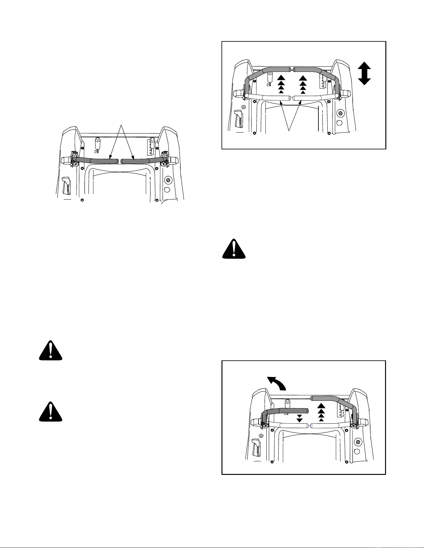
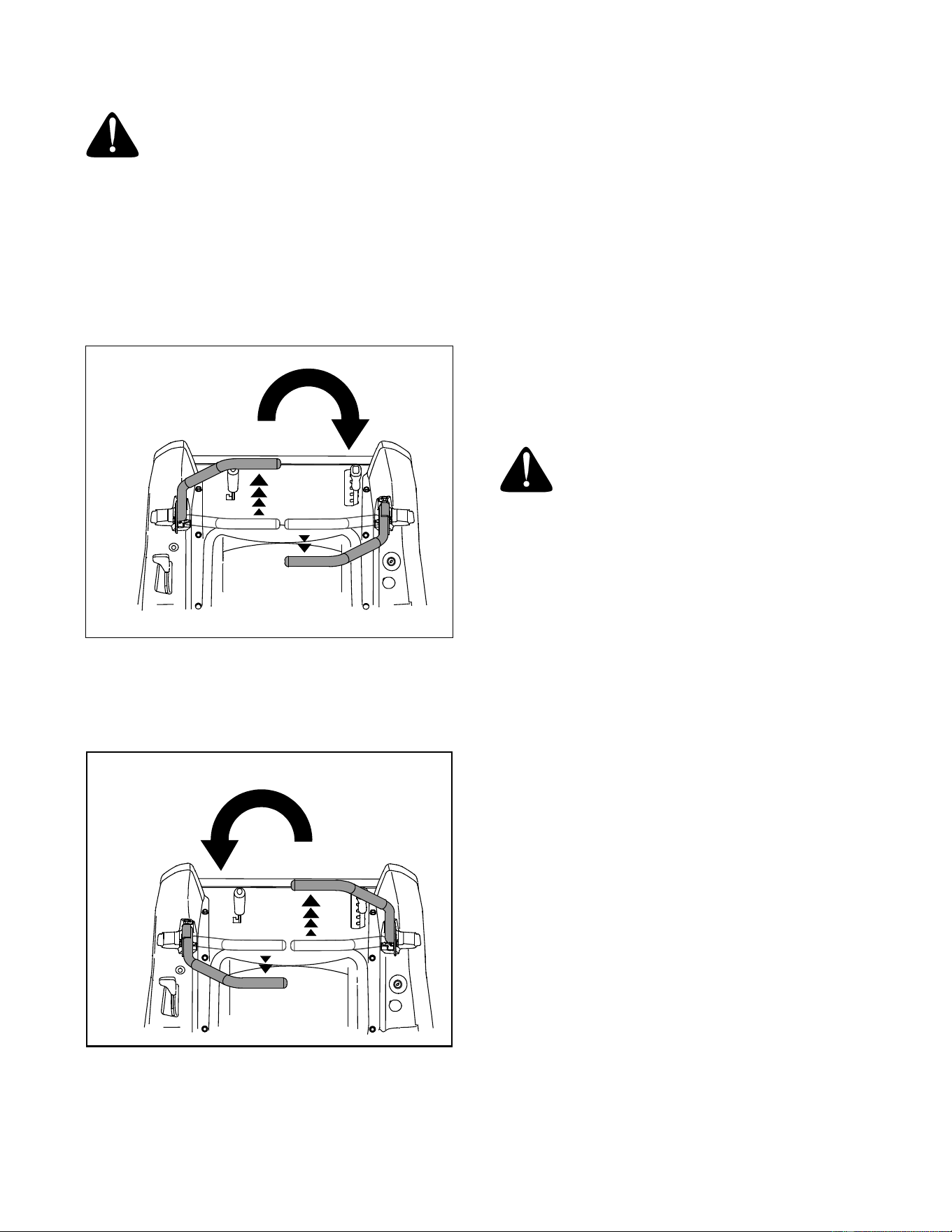
• Move the RH and LH drive control levers inward
in the neutral position. See Figure 9.
Figure 9
• Move the throttle control lever forward to the full
throttle position (3500-3600 RPM). Make certain
the throttle control has not been moved too far
forward into the "Choke" position.
NOTE: The tractor and engine are designed to run at
full throttle. However, if performing a practice session,
it is preferable that the tractor is operated at half
throttle (approximately 2500-2600 RPM), but this only
applies to practice operation.
• To drive the tractor, firmly grasp the respective
drive control levers with your right and left hands
and proceed as follows :
WARNING: Always maintain a firm grip
on the control levers. DO NOT release the
control levers to slow or stop the tractor;
move the levers to the neutral position
using your hands.
Driving the Tractor Forward
WARNING: Keep all movement of the
drive control levers slow and smooth.
Abrubt movement of the control levers
can affect the stability of the tractor and
could cause the tractor to flip over,
which may result in serious injury or
death to the operator.
• Slowly and evenly move both drive control levers
forward. The tractor will start to move forward.
See Figure 10.
• As the control levers are pushed farther forward
the speed of the tractor will increase.
Figure 10
• To slow the tractor move the controls lever
rearward to attain the desired speed, or move the
levers to the neutral position to stop the tractor.
IMPORTANT: Always maintain your grasp on the
drive control levers. Do not release the levers to
slow the tractor or to return to neutral.
Turning the Tractor While Driving Forward
WARNING: When reversing the direction
of travel, we recommend performing
gradual ‘U’ turns where possible.
Sharper turns increase the possibility of
turf defacement, and could affect control
of the tractor. ALWAYS slow the tractor
before making sharp turns.
• To turn the tractor while driving forward, move the
control levers as necessary so that one lever is
rearward of the other. The tractor will turn in the
direction of the rearward control lever.
- To turn to the left, move the left drive control
lever rearward of the right lever. See Figure 11.
Figure 11
Control Lever Moved
Inward and in Neutral
Neutral
Position
DRIVING FORWARD
Slower
Faster
FORWARD LEFT TURN
16
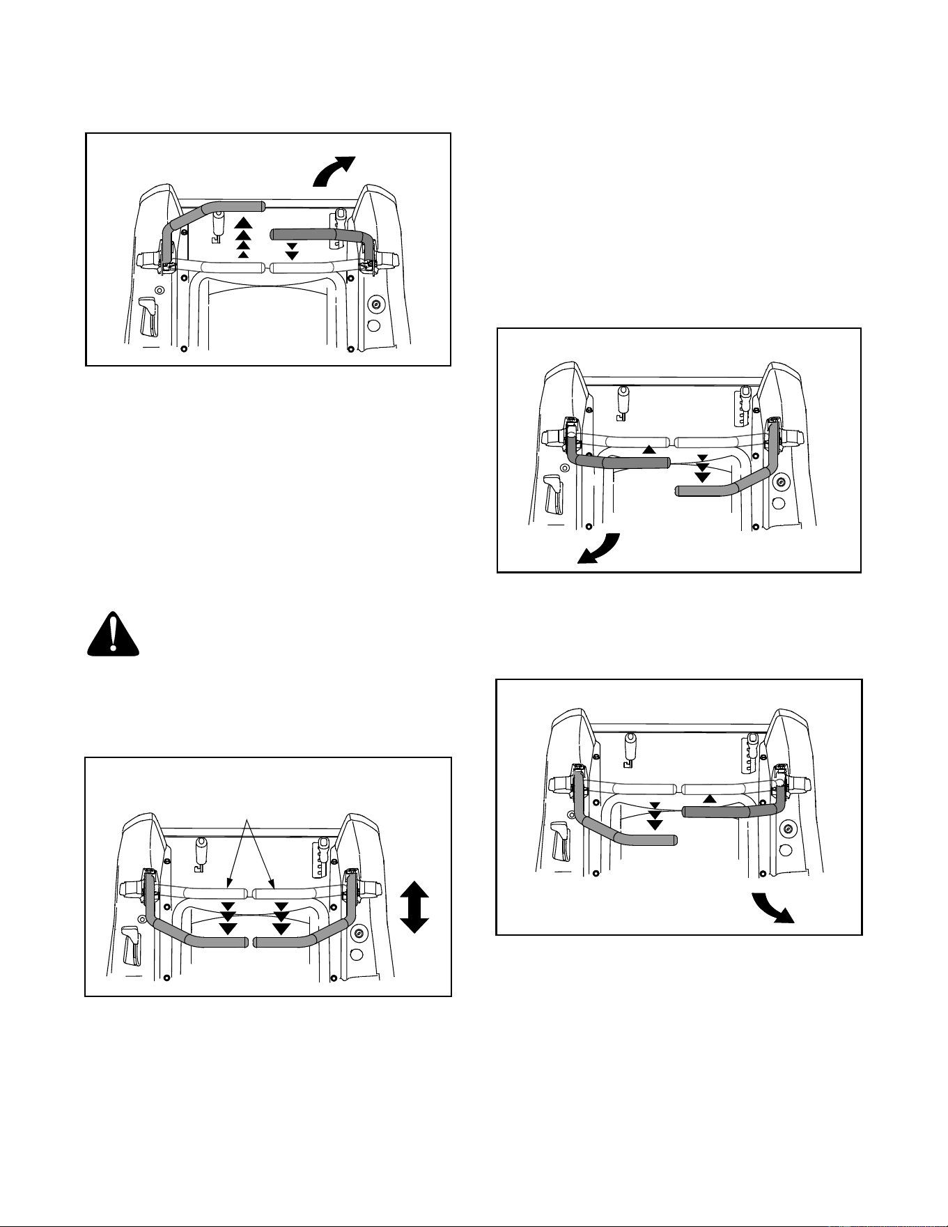
- To turn to the right, move the right drive control
lever rearward of the left lever. See Figure 12.
Figure 12
• The greater the fore-to-aft distance between the
two levers, the sharper the tractor will turn.
• To execute a "pivot turn," move the turn side
drive control lever to the neutral position, while
moving the other control lever forward.
IMPORTANT: Making a "pivot turn" on grass
will greatly increase the potential for
defacement of the turf.
Driving the Tractor In Reverse
WARNING: Always look behind and
down on both sides of the tractor before
backing up. Always look behind while
traveling in the reverse direction.
• Slowly and evenly move both drive control levers
rearward. The tractor will start to move in the
reverse direction. See Figure 13.
Figure 13
• As the control levers are pushed farther rearward
the speed of the tractor will increase.
• To slow the tractor move the controls lever
forward to attain the desired speed, or move the
levers to the neutral position to stop the tractor.
IMPORTANT: Always maintain your grasp on the
drive control levers. Do not release the levers to
slow the tractor or to return to neutral.
Turning While Driving Rearward
• To turn the tractor while driving rearward, move
the control levers as necessary so that one lever
is forward of the other. The tractor will turn in the
direction of the forward control lever.
- To turn to the left while traveling in reverse,
move the left drive control lever forward of the
right lever. See Figure 14.
Figure 14
- To turn to the right while traveling in reverse,
move the right drive control lever forward of the
left lever. See Figure 15.
Figure 15
• The greater the fore-to-aft distance between the
two levers, the sharper the tractor will turn.
• To execute a "pivot turn," move the turn side
drive control lever to the neutral position, while
moving the other control lever rearward.
IMPORTANT: Making a "pivot turn" on grass
will greatly increase the potential for
defacement of the turf.
FORWARD RIGHT TURN
Neutral
Position
DRIVING REARWARD
Slower
Faster
REARWARD LEFT TURN
REARWARD RIGHT TURN
17
Executing a Zero Turn
WARNING: When executing a zero turn,
the tractor MUST BE STOPPED.
Executing a zero turn while the tractor is
moving can significantly reduce your
control of the tractor and will cause
severe turf defacement to occur.
• Stop the forward or reverse motion of the tractor
by moving the two drive control levers to neutral.
• To turn clockwise, slowly move the left control
lever forward while simultaneously moving the
right control lever rearward. See Figure 16.
Figure 16
• To turn counterclockwise, slowly move the right
control lever forward while simultaneously moving
the left control lever rearward. See Figure 17.
Figure 17
STOPPING THE TRACTOR
• Move both drive control levers to the neutral
position to stop the motion of the tractor.
• Push the PTO switch downward to the
disengaged position.
• Use the deck lift handle to raise the deck to its
highest position.
• If dismounting the tractor, move the drive control
handles fully outward in the neutral position,
engage the parking brake, move the throttle
control lever to the fast position, turn the ignition
switch to “OFF’” and remove the key from the
switch.
DRIVING ON SLOPES
Refer to the SLOPE GAUGE on page 29 to help
determine slopes where you may not operate safely.
WARNING: Do not operate on inclines
with a slope in excess of 15 degrees (a
rise of approximately 2-1/2 feet every 10
feet). The tractor could overturn and
cause serious injury.
• Always drive across slopes, NEVER UP AND
DOWN.
• Always turn uphill where possible. Start at the
bottom of a slope and work upward.
• Always slow down before turning.
• Avoid turning downhill if possible. Use extra care
and go slowly when turning downhill.
OPERATING THE PTO
Operate the PTO clutch as follows:
• Move the throttle control lever to approximately
the mid throttle position.
• Pull the PTO switch upward to the “ENGAGED”
position.
• Advance the throttle lever to the operating speed
(full engine speed).
• The operator must remain in the tractor seat at all
times. If the operator should leave the seat
without turning off the power take-off switch, the
tractor’s engine will shut off.
• The PTO clutch cannot be operated when the
tractor is driving in the reverse direction. The
PTO will disengage when both drive control
levers are moved to the reverse position, and will
re-engage when one (or both) control levers are
moved to the neutral or forward position.
CLOCKWISE ZERO TURN
COUNTERCLOCKWISE ZERO TURN

18
USING THE MOWER DECK
WARNING: Make certain the area to be
mowed is free of debris, sticks, stones,
wire or other objects that can be thrown
by the rotating blades.
• Mow across slopes, not up and down. If mowing
a slope, start at bottom and work upward to
ensure turns are made uphill.
• On the first pass pick a point on the opposite side
of the area to be mowed.
• Lower the mower deck to the desired height
setting using the lift handle.
• Engage the PTO clutch using the PTO switch and
move the throttle control to the fast position.
• Slowly and evenly push the RH and LH drive
control levers forward to move the tractor
forward, and keep the tractor headed directly
toward the alignment point.
NOTE: The speed of the tractor will affect the
quality of the mower cut. Mowing at full speed
with adversely affect the cut quality. Control the
ground speed with the control levers.
• When approaching the other end of the strip,
slow down or stop before turning. A U-turn is
recommended unless a pivot or zero turn is
required.
• Align the mower with an edge of the mowed strip
and overlap approximately 3 inches.
• Direct the tractor on each subsequent strip to
align with a previously cut strip.
• To prevent rutting or grooving of the turf, if
possible, change the direction that the strips are
mowed by approximately 45° for the next and
each subsequent mowing.
WARNING: Be careful when crossing
gravel paths or driveways. Disengage
the PTO and raise the deck to the
highest position before crossing.
CHECKING THE SAFETY INTERLOCK CIRCUITS
Periodically check the safety interlock circuits to
ensure they are working properly. If a safety circuit is
not working as designed, contact you Cub Cadet
dealer to have the tractor inspected. DO NOT operate
the tractor if any safety circuit is not functioning
properly. To check the safety circuits, proceed as
follows:
• Sitting in the tractor seat with both drive control
levers opened fully outward, disengage the
parking brake and momentarily turn the ignition
switch to the start position. The engine should not
crank.
• Engage the parking brake and pull the PTO
switch upward to the engaged position.
Momentarily turn the ignition switch to the start
position; the engine should not crank.
• Push the PTO switch downward to the disen-
gaged position and engage the parking brake.
Start the engine and move one of the drive con-
trol levers from the fully outward neutral position.
The engine should stop running. Repeat the pro-
cedure with the opposite control lever.
• Move both control levers fully outward in the neu-
tral position and disengage the parking brake;
then lift upward from the operator’s seat. The
engine should stop.
• With both control levers fully outward in the neu-
tral position and the parking brake engaged,
engage the PTO. Lift upward from the operator’s
seat; the engine should stop.
• Start the tractor, disengage the parking brake,
and move the control levers inward to the neutral
operating position. Engage the PTO and move
both control lever slowly into the slow reverse
position; the PTO should disengage and the
mower deck should stop until one or both of the
control levers are moved to the neutral or for-
ward position.
19
SECTION 3: ADJUSTMENTS
ADJUSTING THE OPERATORS SEAT
The seat may be adjusted fore and aft for the comfort
of the operator. To adjust the seat proceed as follows:
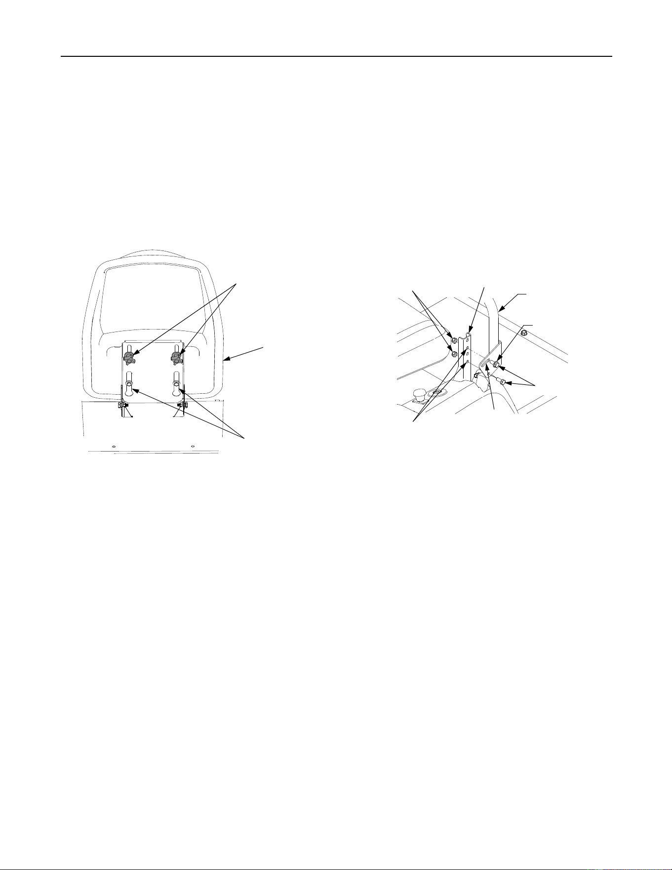
• Pivot the seat partially forward and hold in a
position that allows you to access the wing knobs
on the bottom of the seat.
• Loosen the two wing knobs and slide the seat
forward or backward in the adjustment slots to
the desired position, then retighten the wing
knobs. See Figure 18.
Figure 18
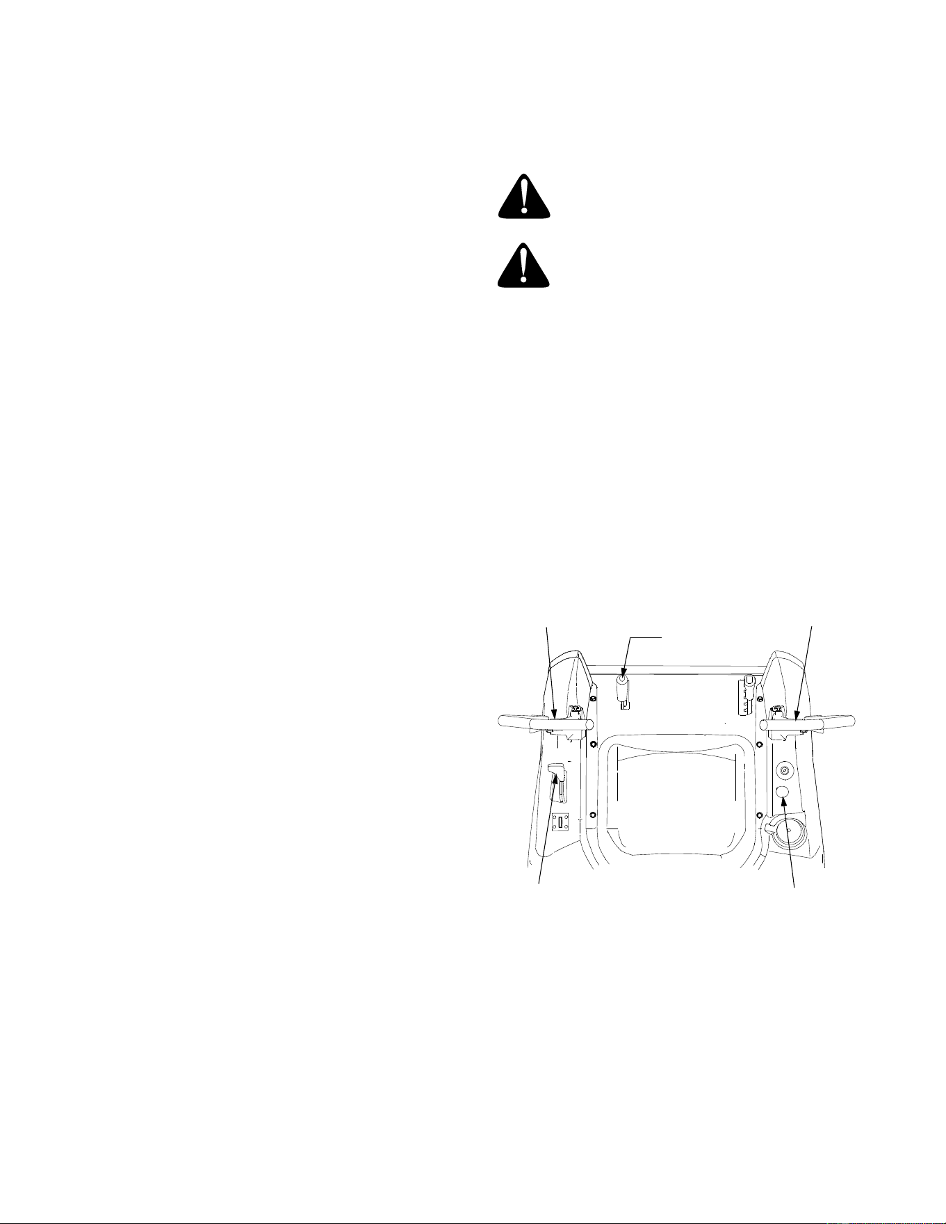
ADJUSTING RH & LH DRIVE CONTROL LEVERS
The RH and LH drive control levers can be adjusted
up or down and fore-and-aft for the comfort of the
operator. The drive control levers can be placed in
either of two height positions, or can be moved
forward or rearward within the range of the upper
slots on each control lever mounting bracket.
To adjust the drive control lever height, proceed as
follows:
• Remove the two hex insert lock nuts securing the
hex cap screws fastening the control lever to the
control pivot bracket. Refer to Figure 19.
• While holding the hex cap screws in the control
lever mounting bracket, remove the control lever
w/screws from the control pivot handle and
reposition by inserting the screws in the other pair
of holes.
• If repositioning the control levers forward or
rearward proceed to the next step. If not, fully
tighten the hex cap screws and hex insert lock
nuts to secure the control levers.
Figure 19
To adjust the drive control levers forward or rearward,
proceed as follows:
• Loosen the two hex insert lock nuts and hex cap
screws securing the control lever to the control
pivot bracket. Refer to Figure 19.
• Rotate the control lever either forward or
rearward to the desired position.
• Tight the two hex insert lock nuts and hex cap
screws to secure in the control lever.
Wing Knobs
Adjustment
Slots
Seat
Control Lever
Hex Insert
Pivot Bracket
Slot
Flat Washer
Hgt. Adjust Holes
Hex Cap Screw
Lock Nut
20
SECTION 4: MAINTENANCE
ENGINE MAINTENANCE
Engine maintenance procedures and schedules can
be found in the engine manual found at the back of
this manual. Follow these schedules for performing
engine maintenance.
Using the Engine Oil Drain Valve
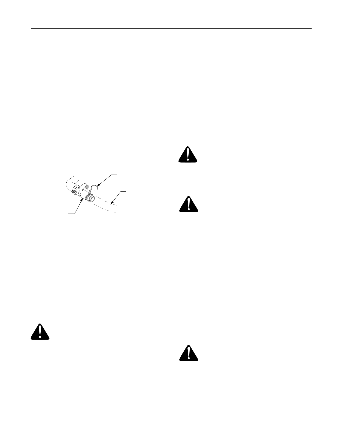
• Locate the oil drain valve on the left side of the
engine.
• Pop open the protective cap on the end of the oil
drain valve to expose the oil drain port. See
Figure 20.
• Push the oil drain hose (packed with this manual)
onto the oil drain port. Route the opposite end of
the hose into an appropriate oil collection
container with a capacity great enough to collect
the used oil (48 oz.; 1.4 liters).
Figure 20
• Push the oil drain valve in slightly, then rotate
counterclockwise and pull outward to begin
draining oil. See Figure 20.
HYDROSTATIC TRANSMISSION MAINTENANCE
The zero turn tractor is equipped with dual integrated
hydrostatic pumps, motors, and transaxles that are
sealed and do not require regular maintenance. All
service work on the hydrostatic transmissions should
be performed by your Cub Cadet dealer.
GENERAL BATTERY INFORMATION
WARNING:
• Battery posts, terminals and related accessories
contain lead and lead compounds. Wash hands
after handling.
• Should battery acid accidentally splatter into the
eyes or onto the skin, rinse the affected area
immediately with clean cold water. If there is any
further discomfort, seek prompt medical attention.
• If acid spills on clothing, first dilute it with clean
water, then neutralize with a solution of ammonia/
water or baking soda/water.
• NEVER connect (or disconnect) battery charger
clips to the battery while the charger is turned on,
as it can cause sparks.
• Keep all sources of ignition (cigarettes, matches,
lighters) away from the battery. The hydrogen
gas generated during charging can be
combustible.
• As a further precaution, only charge the battery in
a well ventilated area.
• Always shield eyes and protect skin and clothing
when working near batteries.
WARNING: Batteries contain sulfuric
acid and may emit explosive gases. Use
extreme caution when handling batter-
ies. Keep batteries out of the reach of
children.
BATTERY REMOVAL
WARNING: Battery posts, terminals and
related accessories contain lead and
lead compounds. Wash hands after
handling.
The battery is located on the right/rear of the tractor
beneath the seat box frame.
To remove the battery:
• Grasp the bottom of the battery holddown strap
and pull downward and rearward to release it
from the tab in the frame.
• Remove the hex cap screw and sems nut secur-
ing the black negative battery lead to the negative
battery post (marked NEG). Move the cable away
from the negative battery post.
• Remove the hex cap screw and sems nut secur-
ing the red positive battery lead to the positive
battery post (marked POS).
• Carefully lift the battery out of the tractor.
Install the battery by repeating the above steps in the
reverse order.
WARNING: Always connect the positive
lead to the battery before connecting the
negative lead. This will prevent sparking
or possible injury from an electrical short
caused by contacting the tractor body
with tools being used to connect the
cables.
Protective
Cap
Oil Drain
Hose
Oil Drain
Valve
Turn and
Pull Out

21
CHARGING THE BATTERY
Test and, if necessary, recharge the battery after the
tractor has been stored for a period of time.
• A voltmeter or load tester should read 12.6 volts
(DC) or higher across the battery terminals.
• Charge the battery with a 12-volt battery charger
at a MAXIMUM rate of 10 amps.
BATTERY MAINTENANCE
The battery is filled with battery acid and then sealed
at the factory. However, even a “maintenance free”
battery requires some maintenance to ensure its
proper life cycle.
• Spray the terminals and exposed wire with a
battery terminal sealer, or coat the terminals with
a thin coat of grease or petroleum jelly, to protect
against corrosion.
• Always keep the battery cables and terminals
clean and free of corrosion.
• Avoid tipping. Even a sealed battery will leak
electrolyte when tipped.
BATTERY STORAGE
• When storing the tractor for extended periods,
disconnect the negative battery cable. It is not
necessary to remove the battery.
• All batteries discharge during storage. Keep the
exterior of the battery clean, especially the top. A
dirty battery will discharge more rapidly.
• The battery must be stored with a full charge. A
discharged battery can freeze sooner than a
charged battery. A fully charged battery will store
longer in cold temperatures than hot.
• Recharge the battery before returning to service.
Although the tractor may start, the engine charging
system may not fully recharge the battery.
SERVICING ELECTRICAL SYSTEM
A fuse is installed to protect the tractor’s electrical
system from damage caused by excessive amper-
age. Always use the same capacity fuse for
replacement. If the electrical system does not func-
tion, check for a blown fuse. See Figure 21
If you have a recurring problem with blown fuses,
have the tractor’s electrical system checked by your
Cub Cadet dealer.
Figure 21
Relays and Switches
There are several relays and safety switches in the
electrical system. If a function of the safety interlock
system described earlier is not functioning properly,
have the electrical system checked by your Cub
Cadet dealer.
LUBRICATION
• Using a pressure lubricating gun, lubricate the
front castor axles with Cub Cadet 251H EP
grease after every 10 hours of service.
• From underneath the left rear of the tractor,
locate the tractor drive belt idler pulley and idler
bracket. Using a pressure lubricating gun,
lubricate the idler bracket with Cub Cadet 251H
EP grease after every 10 hours of service.
• Refer to the "MOWER DECK" section later in this
manual for deck lubrication procedures.
• Periodically lubricate all other pivot points with a
quality lubricating oil.
TIRE MAINTENANCE
Check the tire air pressure after every 50 hours of
operation or weekly. Keep the tires inflated to the
recommended pressures. Improper inflation will
shorten the service life of a tire. See the tire side wall
for proper inflation pressures. Observe the following
guidelines:
• Do not inflate a tire above the maximum pressure
shown on the sidewall of the tire.
• Do not reinflate a tire that has been run flat or
seriously under inflated. Have a qualified tire
mechanic inspect and service the tire.
USING THE TRANSMISSION BYPASS RODS
If for any reason the tractor will not drive or you wish
to move the tractor, the two hydrostatic transmis-
sions are equipped with bypass rod that will allow you
to manually move the tractor short distances.
WARNING: Do not tow the tractor, even
with the bypass rod engaged. Serious
transmission damage will result from
doing so.
Voltmeter
Reading
State of
Charge
Charging
Time
12.7 100% Full Charge
12.4 75% 90 Min.
12.2 50% 180 Min.
12.0 25% 280 Min.
GOOD
BAD
22
• From just in front of the two rear tires, locate the
transmission bypass rods. See Figure 22.
• Pull one rod toward the front of the tractor until
the flange on the rod is forward of the keyhole
slot in the frame assembly.
• Lower the bypass rod into the keyhole slot and
release so the rod flange is against the front of
the frame bracket.
• Repeat the above procedure to engage the other
bypass rod.
Figure 22
• After moving the tractor, disengage both bypass
rods. Lift the rod and guide the flange of the rod
back through the larger circular opening of the
keyhole, then release the rod.
IMPORTANT: The tractor will not drive with the
bypass rods in the engage position.
TRACTOR CREEPING
Creeping is the slight forward or backward movement
of the tractor when the engine is running at high idle
and the drive control levers are opened out in the
neutral position.
If after operating the tractor for some time, it begins to
creep while in the neutral position, adjust the
transmission control rods as follows.
• Place the front of the tractor against an
immovable object (e.g. wall, post, etc.).
• Jack up the rear of the tractor so that both rear
wheels are approximately one inch of the ground.
• With the engine running at high idle and the drive
control levers opened out in the neutral position,
and the parking brake disengaged, check the rear
wheels for rotation.
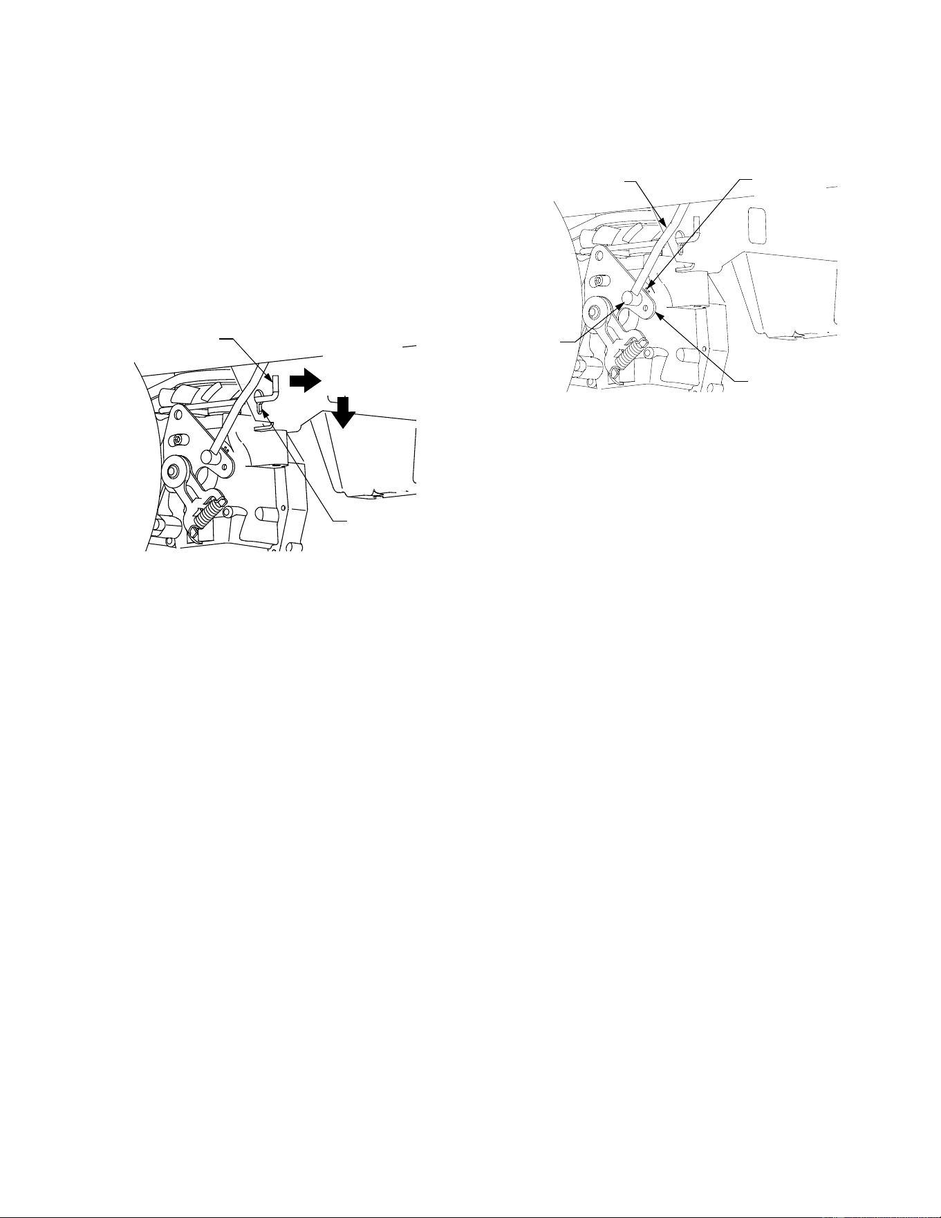
• If only one wheel is rotating, locate the transmis-
sion control rod beneath the frame at the front of
the rear tire. If both wheels rotate, locate both
control rods. See Figure 23.
Figure 23
• Remove the internal cotter pin securing the
ferrule to the transmission control arm and
withdraw the ferrule. Wheel rotation should stop.
If it does not, contact your Cub Cadet dealer.
• If the rotation stops, adjust the ferrule up or down
the control rod as necessary to align with the hole
in the transmission control arm. Re-insert the
ferrule into the hole in the control arm and secure
with the internal cotter pin.
• If necessary, repeat the previous two steps to
adjust the other transmission control rod.
• Lower the tractor and remove the jack.
TRACTOR HIGH SPEED TRACKING
If the tractor tracks to one side with both drive control
levers fully forward, adjust the control levers as
follows:
• Check for proper and balanced air pressure in
both front and rear tires. Refill tires if necessary.
• Perform the first three steps in the previous sub-
section, Tractor Creeping, to verify that the tractor
is not creeping. If creeping, adjust following the
instructions in that sub-section.
• Recheck the tracking after making any adjust-
ments to the transmission control rods.
• If uneven tracking persists, note which direction
the tractor is tracking.
- If the tractor tracks to the right, adjust the
control lever stop bolt on the left side.
- If the tractor tracks to the left, adjust the control
lever stop bolt on the right side.
Keyhole
Slot
Pull out
Bypass Rod
Then Lower
In Slot
RH Transmission
Bypass Rod
Ferrule
Transmission
Control Arm
Internal
Cotter Pin
RH Transmission
Control Rod
23
• Locate the applicable stop bolt on the left or right
console. See Figure 24.
Figure 24
• Loosen the jam nut on the stop bolt, then turn the
stop bolt counterclockwise to make it longer.
Recheck the tracking and fine tune the adjust-
ment as necessary.
NOTE: If the stop bolt is adjusted too far, the
tracking problem will change sides. Make fine
tuning adjustments by shortening the same bolt.
• Tighten the jam nut against the console and repo-
sition the control lever if necessary.
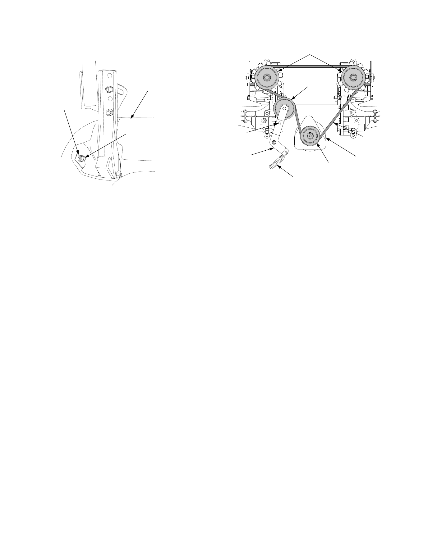
TRANSMISSION DRIVE BELT
If the transmission drive belt becomes worn and
causes the drive transmissions to slip, the drive belt
must be replaced. To replace the drive belt, proceed
as follows:
• Remove the deck drive belt from the PTO clutch
on the bottom of the engine following the instruc-
tions in Deck Removal, SECTION 5: MOWER
DECK.
• From beneath the rear of the tractor, insert a 3/8
inch drive ratchet into the square hole of the drive
idler bracket. See Figure 25.
Figure 25
• Using the ratchet for leverage, pivot the idler
bracket and idler pulley away from the backside
of the ‘V" belt; then lift the belt off and above the
engine pulley and off the idler pulley.
• With the belt loose, lift the belt off, up and over
the two transmission drive pulleys. Remove the
belt from the engine and idler pulleys.
• Loop the new belt and slide over and onto the
two transmission pulleys.
• Route the belt above the idler bracket back to the
engine drive pulley. Lift the belt over the PTO pul-
ley and above the engine drive pulley.
• Using the ratchet for leverage, pivot the idler
bracket and idler pulley against the spring ten-
sion; then slip the belt down into the engine drive
pulley and onto the idler pulley.
• Release the idler bracket so that the idler pulley
tightens against the back side of the belt and ten-
sions the drive belt.
• Reinstall the deck drive belt.
Console
Stop Bolt
Jam Nut
Transmission
Drive Pulley
Idler
Pulley
Engine
Pulley
Drive
Belt
Idler
Bracket
Idler Brkt.
Spring
Square
Hole
PTO
Pulley

24
TRACTOR STORAGE
If your tractor is not going to be operated for an
extended period of time (thirty days to approximately
six months), the tractor should be prepared for stor-
age. Store the tractor in a dry and protected location.
If stored outside, cover the tractor (including the tires)
to protect it from the elements. The procedures out-
lined below should be performed whenever the tractor
is placed in storage.
1. Change the engine oil and filter following the
instructions provided in the engine information at
the back of this manual.
WARNING: Never store the tractor with
fuel in the tank indoors or in poorly ven-
tilated enclosures, where fuel fumes may
reach an open flame, spark or pilot light
as on a furnace, water heater, clothes
dryer, etc.
WARNING: Fuel left in the fuel tank dete-
riorates and will cause serious starting
problems.
2. If storing the tractor for 30 days or more:
To prevent gum deposits from forming inside the
engine’s carburetor and causing possible malfunc-
tion of the engine, the fuel system must be either
completely emptied, or the gasoline must be
treated with a stabilizer to prevent deterioration.
Using a fuel stabilizer:
• Read the product manufacturer’s instructions
and recommendations.
• Add to clean, fresh gasoline the correct amount
of stabilizer for the capacity (approximately 3
gallons) of the fuel system.
• Fill the fuel tank with treated fuel and run the
engine for 2-3 minutes to get stabilized fuel into
the carburetor.
Emptying the fuel system:
• Prior to putting the tractor in storage, monitor
fuel consumption with the goal of running the
fuel tank empty.
• Run the engine until it begins to stall. Use the
choke to keep the engine running until all fuel in
the carburetor has been exhausted.
3. Clean the engine and the entire tractor
thoroughly.
4. Fully charge the battery, then disconnect the neg-
ative cable at the battery to prevent possible
discharge. Recharge the battery periodically
when in storage.
NOTE: Remove the battery if exposed to prolonged
periods of sub-freezing temperatures. Store in a cool,
dry location where temperatures are above freezing.
5. Lubricate all lubrication points.
NOTE: We do not recommend the use of a pressure
washer or garden hose to clean your unit. They may
cause damage to electrical components; spindles;
pulleys; bearings; or the engine. The use of water will
result in shortened life and reduce serviceability.
REMOVING THE TRACTOR FROM STORAGE
• Check the engine oil.
• Fully charge the battery and inflate the tires to the
recommended pressure.
• Start the engine and allow to idle for a few
minutes to ensure engine is operating properly.
• Drive the tractor without a load to make certain all
the tractor systems are functioning properly.
25
SECTION 5: MOWER DECK
This section contains removal, installation, adjust-
ment, and maintenance information for the 42-inch
mower deck.
DECK REMOVAL
Remove the mower deck from the tractor as follows:
• Move the tractor to a level surface, disengage the
PTO, stop the engine, and set the parking brake.
• Move the deck gauge wheels to their highest
setting (lowest deck setting).
• Lower the deck to the ground using the deck lift
handle.
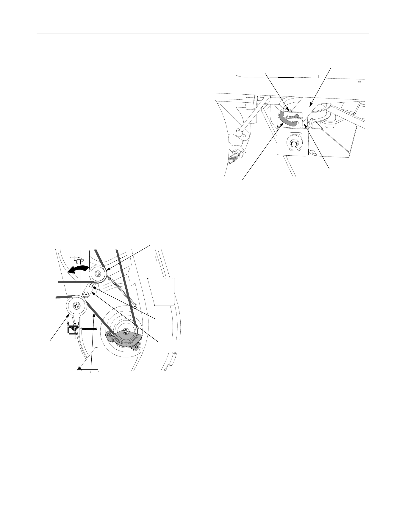
• From beneath the middle of the tractor, insert a
1/2 inch ratchet into the square hole of the deck
idler bracket. See Figure 26.
• Using the ratchet for leverage, pivot the idler
bracket and movable idler pulley away from the
backside of the ‘V" belt; then lift the belt off of
both the movable and fixed idler pulleys. See
Figure 26.
Figure 26
• From beneath the rear of the tractor, slide the belt
off of the PTO pulley on the bottom of the engine.
• Looking at the cutting deck from the right side of
the tractor, locate the deck support pin on the
rear right side of the deck. See Figure 27.
• Pull the deck support pin outward to release the
right side of the deck from the deck lift arm. See
Figure 27.
Figure 27
• From the left side of the tractor release the left
side of the deck by pulling the left deck support
pin outward.
• Raise the deck lift arms out of the rear hanger
bracket slots by raising the deck lift handle on the
tractor to its highest position.
• Slide the deck forward so that the deck front
hanger rod can be lifted out of the two slots of the
front deck bracket. After lifting the front hanger
rod out of the slots, slide the deck rearward so
that the rod can no longer engage the slots.
• Using care to prevent the front hanger rod from
falling back into the deck slots, gently slide the
cutting deck (from the right side) out from
underneath the tractor.
DECK INSTALLATION
To install the mower deck, proceed as follows:
• While holding up the deck front hanger rod,
carefully slide the deck underneath the right side
of the tractor.
• While still holding the front hanger rod, slide the
deck forward until the front hanger rod can be
lowered into the slots at the front of the deck.
• Lower the front hanger rod into the slots of the
front deck bracket, then slide the deck rearward.
• Maneuver the deck so that the slots in the two
rear deck hanger brackets approximately align
with the deck lift arms of the tractor. Refer to
Figure 27.
Fixed Idler
Pulley
Movable Idler
Pulley
Square
Hole
‘V’ Belt
Idler Bracket
Deck
Deck Lift Arm
Support
Pin
Rear Deck
Hanger Bracket
Rear Hanger
Bracket Slot
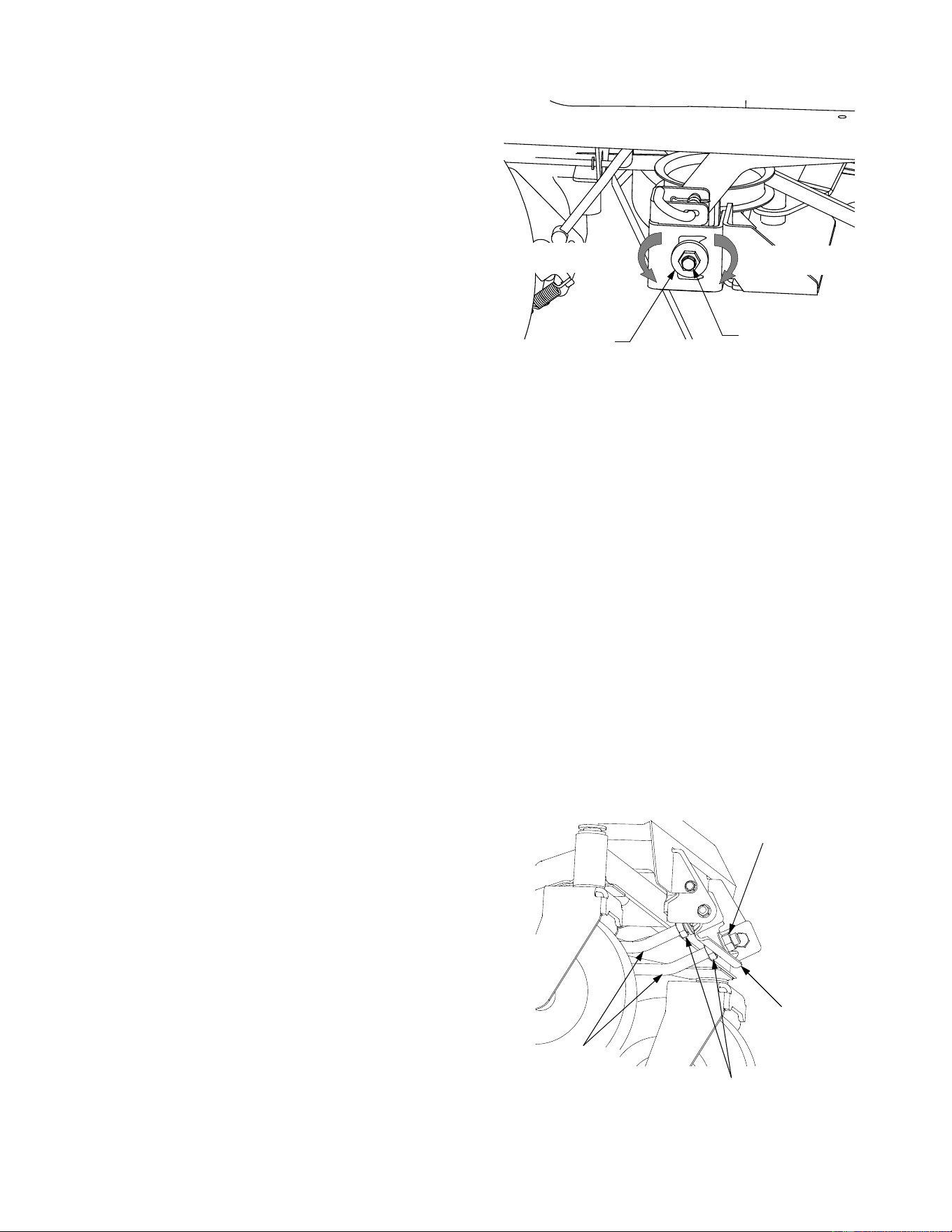
26
• Use the deck lift handle of the tractor to lower the
deck lift arms into the slots of the rear deck
hanger brackets.
• Pull the deck support pins outward and maneuver
the deck as necessary to align the holes in the
deck lift arm with the pins. Refer to Figure 27.
• When aligned, push each pin fully inward through
the lift arms to secure the arms in the rear hanger
bracket slots.
• Route the ‘V’ belt rearward beneath the tractor
frame and install the belt in the pulley of the PTO
clutch.
• Route the backside of the belt around the fixed
idler pulley of the deck. Refer to Figure 26.
• Insert a 1/2 inch ratchet into the square hole of
the deck idler bracket. Refer to Figure 26.
• Using the ratchet for leverage, pivot the idler
bracket rearward against the spring tension and
slide the backside of the belt onto the movable
idler pulley. Refer to Figure 26.
LEVELING THE MOWER DECK
When leveled correctly the mower deck should be
level side to side, and should be approximately a 1/8
to 1/4 inch lower in the front of the deck.
Side to Side Leveling
If the cutting deck appears to be mowing unevenly, a
side to side adjustment can be performed. Adjust if
necessary as follows:
• With the tractor parked on a firm, level surface,
place the deck lift handle in the top notch (highest
position) and rotate both blades so that they are
perpendicular to the tractor frame.
• Measure the distance from the outside left blade
tip to the ground and the distance from the
outside right blade tip to the ground. The
measurements should be equal. If they’re not,
proceed to the next step.
• Comparing the two measurements, determine
whether the right side of the deck must be raised
or lowered.
• Loosen, but do not remove, the hex cap screw on
the right deck hanger bracket. Refer to Figure 28.
• Level the deck by using a wrench to turn the
adjustment gear (found immediately behind the
hex cap screw just loosened) clockwise to lower
the right side of the deck, or counterclockwise to
raise the right side of the deck. Refer to Figure 28.
• The deck is properly leveled when both blade tip
measurements taken earlier are equal.
• Retighten the hex cap screw on the left deck
hanger bracket when proper adjustment is
achieved.
Figure 28
Front to Back Leveling.
The front of the deck should be approximately 1/8 to
1/4 inch lower than the rear of the deck. Adjust if nec-
essary as follows:
• With the deck raised off of the ground, rotate the
blades so that they are parallel to the frame of the
tractor.
• If the side to side leveling was done correctly,
measuring just the right blade should be
acceptable to attain the correct back to front pitch
of the deck.
• Measure the distance from the front tip of the
blade to the ground and the distance from the
rear tip to the ground. The front distance should
be 1/8 to 1/4 inch less than the rear. If it is not,
proceed to the next step.
• From the front of the tractor, on the rearward side
of the front hanger rod bracket, locate the two
hex jam nuts on the deck front hanger rod. See
Figure 29.
Figure 29
Adjustment
Gear
Hex Cap
Screw
Lower RT.
Side of Deck
Raise RT.
Side of Deck
Front Hanger
Rod Bracket
Hex Jam Nut
Hex Flange Nut
Front
Hanger
Rod
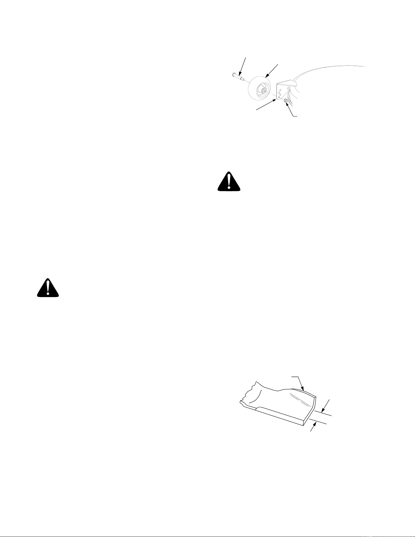
27
• Loosen the two hex jam nuts and turn them away
from the backside of the front hanger rod bracket.
• If the front of the deck was too low, turn the hex
flange nuts on the ends of the front hanger rod
clockwise to raise the front of the deck. See
Figure 29.
• If the front of the deck was too high, turn the hex
flange nuts counterclockwise to lower the front of
the deck.
IMPORTANT: The deck front hanger rod should
be at the front of the slots of the front deck
bracket. If one side of the rod is not at the front of
its slot, turn the hex flange nut on the that side
until rod just touches the front of the slot. Then
re-measure and re-adjust the front hanger rod as
necessary.
• When the correct pitch of the deck is acquired,
tighten the hex jam nuts against the front hanger
rod bracket.
ADJUSTING THE GAUGE WHEELS
The cutting height of the mower deck can be set in
any of six height settings using the deck lift handle of
the tractor. The deck heights range from 1-1/2 inches
to 4 inches. The deck gauge wheel position should be
approximately 1/4 to 1/2 inch above the ground when
the deck is set in the desired height setting.
WARNING: Keep hands and feet away
from the discharge opening of the
cutting deck.
NOTE: The deck wheels are an anti-scalp feature of
the deck and are not designed to support the weight of
the cutting deck.
Using the lift handle, set the deck in the desired
height setting, then check the gauge wheel and if
necessary adjust as follows.
• With the deck set at the desired height, visually
check the distance between the gauge wheels
and the ground. If the gauge wheels are near or
touching the ground, they should be raised. If the
gauge wheels are too high, they should be
lowered.
• Remove the lock nut securing one of the gauge
wheel shoulder screws to the deck. Remove the
gauge wheel and shoulder screw. See Figure 30.
• Insert the shoulder screw in the one of four index
holes that will give the gauge wheel a 1/4 to 1/2
inch clearance with the ground.
• Note the index hole of the just adjusted wheel,
and adjust the other gauge wheel into the
respective index hole on the other side of the
deck.
Figure 30
DECK MAINTENANCE
Cleaning And Blade Care
WARNING: Before performing any main-
tenance, place the PTO switch in the
“OFF” position, engage the parking
brake lever, turn the ignition key to the
“OFF” position and remove the key from
the switch. When servicing the mower
deck, be careful not to cut yourself on
the sharpened blades.
Clean the underside of the mower deck at the end of
the mowing season or when buildup of cut material
on the underside is noticed.
Once a month remove the belt covers to remove any
accumulation of grass clippings from around the
spindle pulleys and V-belt. Clean more often when
mowing tall, dry grass.
The cutting blades must be kept sharp at all times.
Sharpen the cutting edges of the blades evenly so
that the blades remain balanced and the same angle
of sharpness is maintained. If the cutting edge of a
blade has been sharpened to within 5/8 inch of the
wind wing radius, it is recommended that new blades
be installed. See Figure 31.
Figure 31
The blades may be removed as follows.
• Remove the deck from beneath the tractor, (refer
to Deck Removal on page 25) then gently flip the
deck over to expose its underside.
Lock
Nut
Rear
Wheel
Gauge
Shoulder
Screw
Gauge
Wheel
Bracket
Wind
Wing
5/8" From
Radius
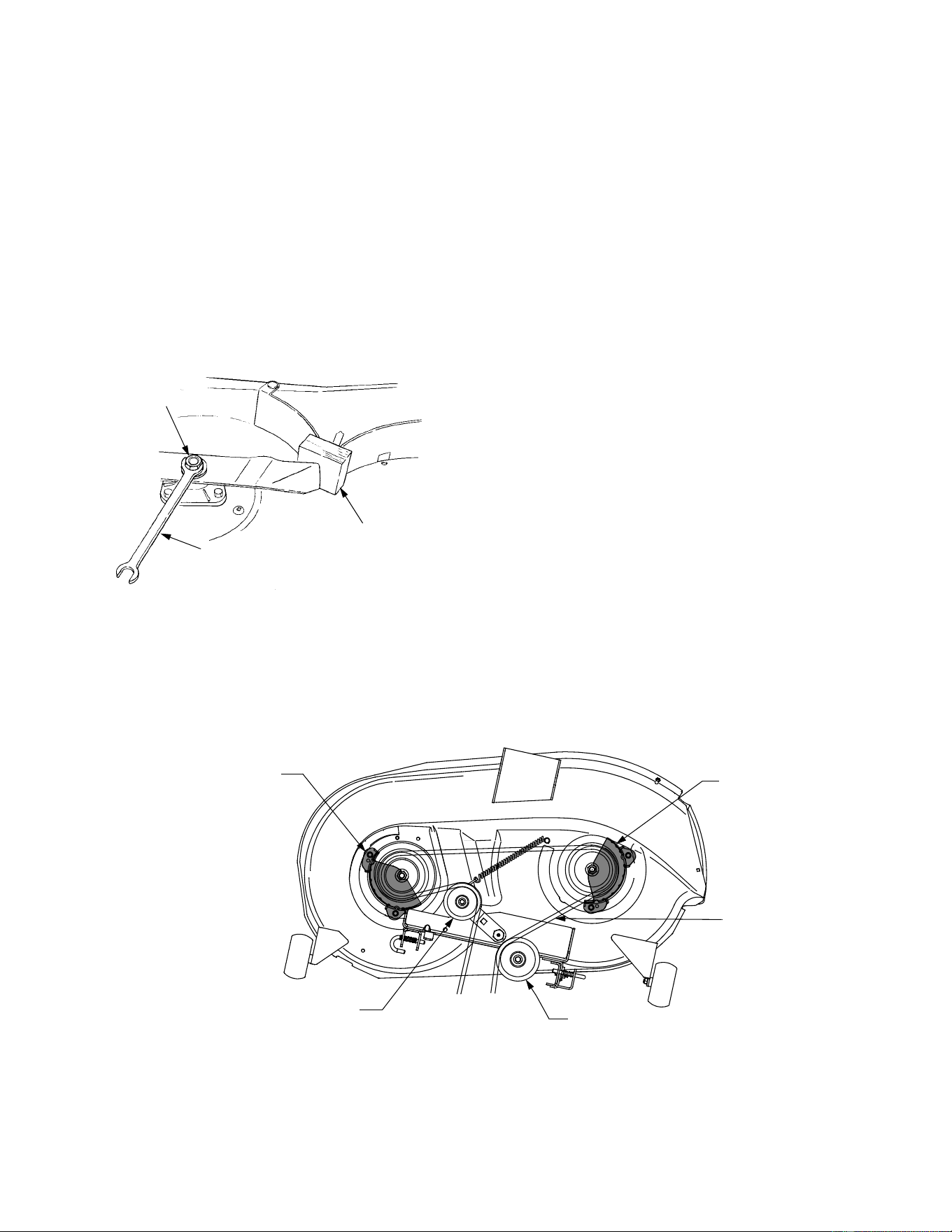
28
• Use a 15/16 inch wrench to hold the hex nut on
top of the spindle assembly when loosening the
hex nut securing the blade. A block of wood may
be placed between the deck housing and the
cutting edge of the blade to assist in removal of
the hex nut securing the blade. Refer to Figure
32.
• When reinstalling the blades, be sure they are
installed so that the wind wings are pointing
upward toward the top of the deck.
• Reinstall the deck (refer to Deck Installation on
page 25).
Figure 32
DECK LUBRICATION
• After every 10 hours of operation and/or before
putting the deck into winter storage, lubricate
the spindle assemblies with 251H EP grease or
an equivalent No. 2 multipurpose lithium
grease. The lube fittings are located in the
spindle housing and can be accessed from
underneath the deck.
• After every 10 hours of operation and/or before
putting the deck into winter storage, lubricate
the spindle belt idler bracket with 251H EP
grease or an equivalent No. 2 multipurpose
lithium grease. The lube fitting is located in the
top of the shoulder bolt securing the idler
bracket.
• After every 25 hours of operation and/or before
putting the deck into winter storage, lubricate
the deck gauge wheels with 251H EP grease or
an equivalent No. 2 multipurpose lithium
grease.
REPLACING THE DECK DRIVE BELT
• Remove the deck from beneath the tractor, (refer
to Deck Removal on page 25).
• Remove the hex tapping screws securing the belt
covers to the deck and remove the belt from the
spindle pulleys. Refer to Figure 33.
• Install the new belt around the spindle pulleys
and reinstall the belt covers.
• Route the belt rearward between the two idler
pulleys and reinstall the deck following the
instructions in Deck Installation on page 25.
Figure 33
Hex Nut
15/16" Wrench
Wood Block
In Position
‘V’ Belt
Belt Cover
Idler Pulley
Belt Cover
Idler Pulley
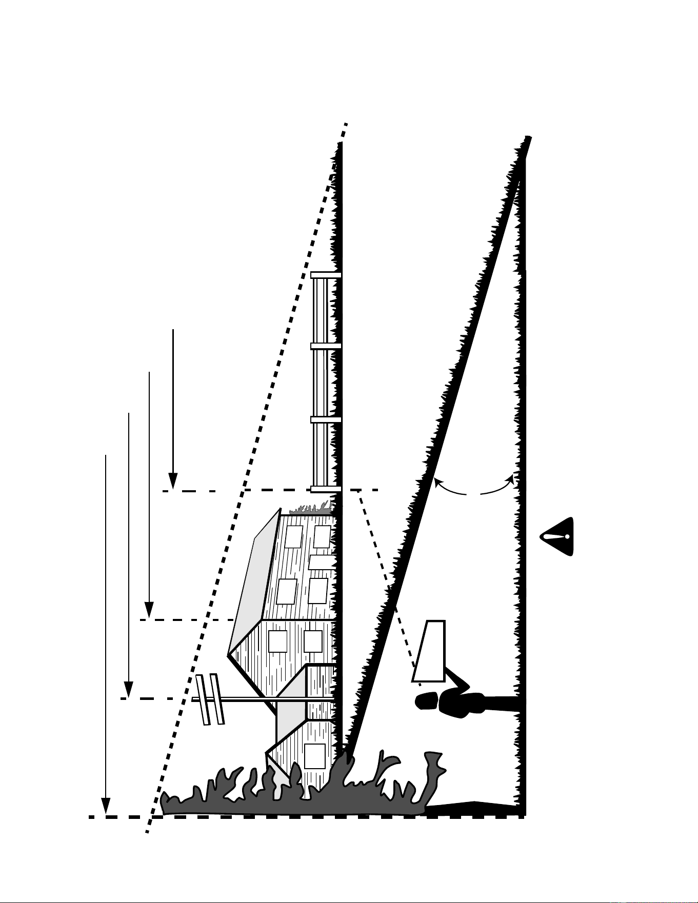
29
SLOPE GAUGE
(Keep this sheet in a safe place for future reference.)
15°
SIGHT AND HOLD THIS LEVEL WITH A VERTICAL TREE
A POWER POLE
A CORNER OF A BUILDING
OR A FENCE POST
F
O
L
D
O
N
D
O
T
T
E
D
L
I
N
E,
R
E
P
R
E
SE
N
T
I
N
G
A
1
5
°
SL
OP
E
USE THIS PAGE AS A GUIDE TO DETERMINE SLOPES WHERE YOU MAY NOT OPERATE SAFELY.
WARNING
Do not mow on inclines with a slope in excess of 15 degrees (a rise of approximately 2-1/2 feet every 10 feet).
A riding mower could overturn and cause serious injury. If operating a walk-behind mower on such a slope, it is
extremely difficult to maintain your footing and you could slip, resulting in serious injury.
Operate RIDING mowers up and down slopes, never across the face of slopes.
Operate WALK-BEHIND mowers across the face of slopes, never up and down slopes.

30

31
ENGINE MANUAL
The Briggs & Stratton model 31F777-0318-E1 engine is used on this RZT model tractor. The following section is a
reproduction of the Briggs & Stratton engine manual that applies to the above engine.
Read this manual in its entirety. Observe all warnings and follow all operation and maintenance instructions pro-
vided in the manual. However, if you experience any engine problems, or have any questions regarding your
engine, contact your Cub Cadet dealer first.
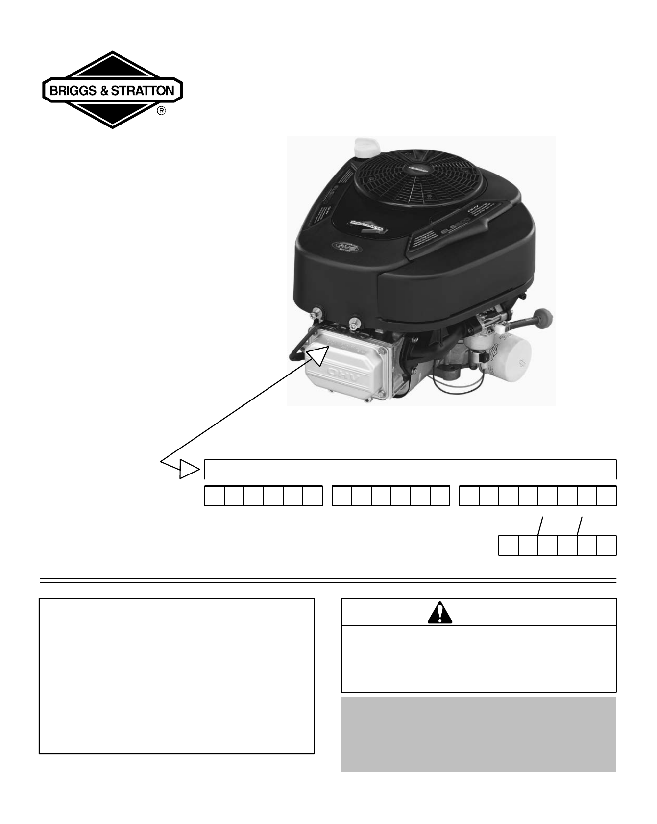
Document: - page 1 (Black)
Screen angle and frequency: 45.0000, 150.0000
Model Series
Covered in
This Manual
Include Gasoline,
Natural Gas and
Liquid Propane
Gas Engines
Operating & Maintenance
Instructions
Model Type Code
Month Day
Note: General Model Series numbers noted above are inclusive of the specific model
number found on your engine. To get replacement parts or technical assistance in the
future, write your engine Model, Type, Code and date of purchase here.
210000
280000
310000
Year
TABLE OF CONTENTS
Safety 3-5. . . . . . . . . . . . . . . . . . . . . . . . . . . . . . . . .
Engine Information 6. . . . . . . . . . . . . . . . . . . . . . . .
Oil 7. . . . . . . . . . . . . . . . . . . . . . . . . . . . . . . . . . . . . . .
Fuel and Starting Information 8. . . . . . . . . . . . . . .
Starting and Stopping 9-10. . . . . . . . . . . . . . . . . . .
Maintenance 11-13. . . . . . . . . . . . . . . . . . . . . . . . .
Adjustments 14. . . . . . . . . . . . . . . . . . . . . . . . . . . . .
Parts and Service & Storage 15-16. . . . . . . . . . . .
Warranty Information 17. . . . . . . . . . . . . . . . . . . . .
WARNING
Briggs & Stratton does not approve or authorize the use of
these engines on 3-wheel All Terrain Vehicles (ATVs), motor
bikes, aircraft products or vehicles intended for use in
competitive events. Use of these engines in such applications
could result in property damage, serious injury (including
paralysis), or even death.
Need assistance? Go to www.briggsandstratton.com
for detailed information regarding
Briggs & Stratton engines.
Or call,
1-800-233-3723, (U.S.A. and Canada)
to hear a menu of pre-recorded messages
offering engine maintenance information.
PRINTED IN U.S.A. Copyright 2003 by Briggs & Stratton Corporation FORM NO. 275935-11/03

Document: - page 2 (Black)
Screen angle and frequency: 45.0000, 150.0000
2
The Power That Works For You.
Look For Relevant Emissions Durability Period and
Air Index Information On Your Engine Emissions Label
Engines that are certified to meet the California Air Resources Board (CARB) Tier 2 Emission Standards must display information regard-
ing the Emissions Durability Period and the Air Index. Briggs & Stratton makes this information available to the consumer on our emission
labels.
The Emissions Durability Period describes the number of hours of actual running time for which the engine is certified to be emissions
compliant, assuming proper maintenance in accordance with the Operating & Maintenance Instructions. The following categories are
used:
Moderate: Engine is certified to be emission compliant for 125 hours of actual engine running time.
Intermediate: Engine is certified to be emission compliant for 250 hours of actual engine running time.
Extended: Engine is certified to be emission compliant for 500 hours of actual engine running time.
For example, a typical walk-behind lawn mower is used 20 to 25 hours per year. Therefore, the Emissions Durability Period of an en-
gine with an intermediate rating would equate to 10 to 12 years.
The Air Index is a calculated number describing the relative level of emissions for a specific engine family. The lower the Air Index, the
cleaner the engine. This information is displayed in graphical form on the emissions label.
After July 1, 2000, Look For Emissions Compliance Period On
Engine Emissions Compliance Label
After July 1, 2000 certain Briggs & Stratton engines will be certified to meet the United States Environmental Protection Agency (USEPA)
Phase 2 emission standards. For Phase 2 certified engines, the Emissions Compliance Period referred to on the Emissions Compliance
label indicates the number of operating hours for which the engine has been shown to meet Federal emission requirements. For engines
less than 225 cc displacement, Category C = 125 hours, B = 250 hours and A = 500 hours. For engines of 225 cc or more, Category
C = 250 hours, B = 500 hours and A = 1000 hours.
The displacement engines of Model Series 210000 is 344 cc, 280000 is 465 cc, 310000 engines is 501 cc.
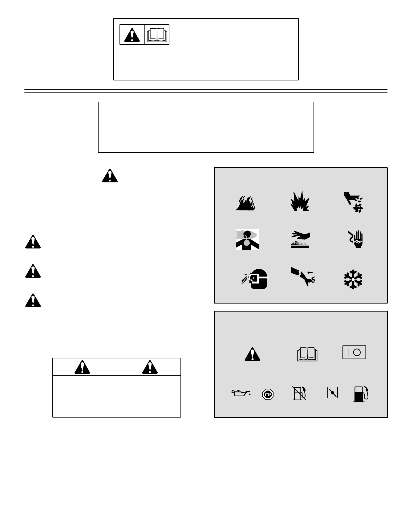
Document: - page 3 (Black)
Screen angle and frequency: 45.0000, 150.0000
3
BEFORE OPERATING ENGINE
• Read entire Operating & Maintenance Instructions AND
the instructions for the equipment this engine powers.*
• Failure to follow instructions could result in serious injury
or death.
THE OPERATING & MAINTENANCE INSTRUCTIONS
CONTAIN SAFETY INFORMATION TO
• Make you aware of hazards associated with engines
• Inform you of the risk of injury associated with those hazards, and
• Tell you how to avoid or reduce the risk of injury.
275935
The safety alert symbol ( ) is used to identify safety
information about hazards that can result in personal injury.
A signal word (DANGER, WARNING, or CAUTION) is
used with the alert symbol to indicate the likelihood and the
potential severity of injury. In addition, a hazard symbol
may be used to represent the type of hazard.
DANGER indicates a hazard which, if not
avoided, will result in death or serious injury.
WARNING indicates a hazard which, if not
avoided, could result in death or serious injury.
CAUTION indicates a hazard which, if not
avoided, might result in minor or moderate
injury.
CAUTION, when used without the alert symbol,
indicates a situation that could result in damage
to the engine.
WARNING
The engine exhaust from this
product contains chemicals known
to the State of California to cause
cancer, birth defects, or other
reproductive harm.
HAZARD SYMBOLS AND MEANINGS
Explosion
Toxic Fumes
Moving Parts
ShockHot Surface
Kickback
Fire
THE INTERNATIONAL SYMBOLS USED
ON THE ENGINE OR
IN THIS MANUAL INCLUDE:
On Off
Fuel Shutoff
Read Owner’s
Manual
Stop Fuel
Choke
Safety Alert
Oil
Frostbite
Wear Eye Protection
* Briggs & Stratton does not necessarily know what equipment this engine will power. For that reason, you should carefully read
and understand the operating instructions for the equipment on which your engine is placed.
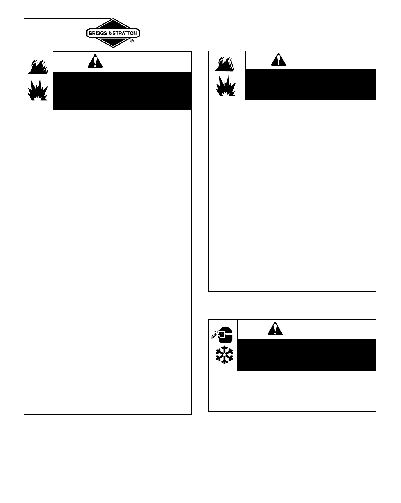
Document: - page 4 (Black)
Screen angle and frequency: 45.0000, 150.0000
4
SAFETY
Fuel and its vapors are extremely flammable
and explosive.
Fire or explosion can cause severe burns or
death.
WARNING
WHEN FUELING
• Turn engine OFF and let engine cool at least 2 minutes
before removing cap or refueling engine.
• Fill fuel tank outdoors or in well-ventilated area.
• On GASOLINE operated engines, do not overfill fuel
tank. Fill tank to approximately 1-1/2 inches below top of
neck to allow for fuel expansion.
• Keep fuel away from sparks, open flames, pilot lights,
heat, and other ignition sources.
• Check fuel lines, tank, cap, and fittings frequently for
cracks or leaks. Replace if necessary.
WHEN STARTING ENGINE
• Make sure spark plug, muffler, fuel cap and air cleaner
are in place, and firmly secured by equipped fasteners.
• Do not crank engine with spark plug, air cleaner cartridge
or air cleaner cover removed.
• If fuel spills, wait until it evaporates before starting engine.
• If GASOLINE engine floods, set choke to OPEN/RUN
position, place throttle in FAST and crank until engine
starts.
WHEN OPERATING EQUIPMENT
• Do not tip engine or equipment at angle which causes
gasoline to spill.
• Do not choke carburetor to stop engine.
WHEN TRANSPORTING EQUIPMENT
• On GASOLINE engine, transport with fuel tank EMPTY or
with fuel shut-off valve OFF.
• On NATURAL / LIQUID PETROLEUM (LP) GAS
engines transport with fuel cylinder empty or valve
closed, or tank disconnected.
WHEN STORING GASOLINE OR EQUIPMENT WITH
FUEL IN TANK
• Store away from furnaces, stoves, water heaters or other
appliances that have pilot light or other ignition source
because they can ignite gasoline vapors.
WARNING
Gaseous fuels are extremely flammable
and readily form explosive air-vapor mix-
tures at ambient temperatures.
IF YOU SMELL GAS:
• DO NOT start the engine.
• DO NOT actuate any electrical switches.
• DO NOT use the phone in the vicinity.
• Evacuate the area.
• Contact the gas supplier or fire department.
REMEMBER:
• LPG vapor is heavier than air and trends to collect in low
areas. NG vapor is lighter than air and tends to collect in
high areas. Both may travel to remote locations.
• Keep all flames, sparks, pilot lights, and other ignition
sources away from the area where the engine is operated
or repaired.
• DO NOT smoke when operating or repairing the engine.
• DO NOT store gasoline or other flammable vapors or
liquids in the vicinity of the engine.
• BEFORE doing any service work to the engine, shut off
the gas supply.
• After initial installation or servicing, check for gas leaks.
DO NOT use an open flame. Apply very soapy water or
leak test solution with a brush and look for bubbles.
• Keep the equipment and the area surrounding the engine
free of debris.
• Install the fuel system according to applicable fuel/gas
codes.
WARNING
Wear eye protection when doing repair work.
Frostbite can result from skin/eye contact with
leaking LP liquid.
• Installation, adjustment and repair work should be done by a
qualified technician.
• Flexible supply lines should be checked regularly to make
sure they are in good condition. Replace damaged or
leaking components.

Document: - page 5 (Black)
Screen angle and frequency: 45.0000, 150.0000
5
SAFETY
Starting engine creates sparking.
Sparking can ignite nearby flammable gases.
Explosion and fire could result.
WARNING
• If there is natural or LP gas leakage in area, do not start
engine.
• Do not use pressurized starting fluids because vapors
are flammable.
WARNING
• When starting engine, pull cord slowly until resistance is
felt, then pull rapidly.
• Remove all external equipment/engine loads before
starting engine.
• Direct coupled equipment components such as, but not
limited to, blades, impellors, pulleys, sprockets, etc.,
must be securely attached.
Rapid retraction of starter cord (kickback) will pull
hand and arm toward engine faster than you can let
go.
Broken bones, fractures, bruises or sprains could
result.
WARNING
Rotating parts can contact or entangle hands,
feet, hair, clothing, or accessories.
Traumatic amputation or severe laceration can
result.
• Operate equipment with guards in place.
• Keep hands and feet away from rotating parts.
• Tie up long hair and remove jewelry.
• Do not wear loose-fitting clothing, dangling drawstrings or
items that could become caught.
Engines give off carbon monoxide, an odorless,
colorless, poison gas.
Breathing carbon monoxide can cause nausea,
fainting or death.
WARNING
• Start and run engine outdoors.
• Do not start or run engine in enclosed area, even if doors
or windows are open.
WARNING
Running engines produce heat. Engine parts,
especially muffler, become extremely hot.
Severe thermal burns can occur on contact.
Combustible debris, such as leaves, grass,
brush, etc. can catch fire.
• Allow muffler, engine cylinder and fins to cool before
touching.
• Remove accumulated combustibles from muffler area
and cylinder area.
• Install and maintain in working order a spark arrester
before using equipment on forest-covered, grass-cov-
ered, brush-covered unimproved land. The state of
California requires this (Section 4442 of the California
Public Resources Code). Other states may have similar
laws. Federal laws apply on federal land.
WARNING
Unintentional sparking can result in fire or
electric shock.
Unintentional start-up can result in entangle-
ment, traumatic amputation, or laceration.
BEFORE PERFORMING ADJUSTMENTS OR REPAIRS
• Disconnect spark plug wire and keep it away from spark
plug.
• Disconnect battery at negative terminal (only engines
with electric start).
WHEN TESTING FOR SPARK
• Use approved spark plug tester.
• Do not check for spark with spark plug removed.
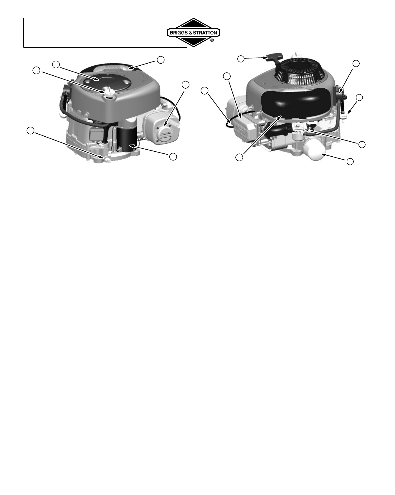
Document: - page 6 (Black)
Screen angle and frequency: 45.0000, 150.0000
6
ENGINE INFORMATION
1. Oil drain
2. Oil fill/Dipstick
3. Rotating screen
4. Air cleaner handle
5. Muffler/(Muffler guard, if equipped)/
(Spark arrester, if equipped)
6. 12 V electric starter
7. Rewind starter handle
8. Fuel pump (if equipped)
9. In-line fuel filter (if equipped)
10. Carburetor or LPG / NG Mixer
11. Oil filter (if equipped)
12. Air cleaner cover
13. Spark plug wire
14. Engine
Model Type Code
xxxxx xxxx xx xxxxxxxx
7
11
12
9
8
10
2
3
4
6
1
5
13
14
GENERAL INFORMATION
ENGINE MODEL: This is a single cylinder, overhead valve
(OHV), air-cooled engine. It is a low emissions engine.
In the state of California, OHV Model Series 210000, 280000 and
310000 engines are certified by the California Air Resources
Board to meet emissions standards for 250 hours. Such
certification does not grant the purchaser, owner or operator of this
engine any additional warranties with respect to the performance
or operational life of this engine. This engine is warranted solely
according to the product and emissions warranties stated
elsewhere in this manual.
TUNE-UP SPECIFICATIONS
Armature air gap 0.010 – 0.014 in. (0.25 – 0.36 mm). . . . . . . . .
Spark plug gap 0.030 in. (0.76 mm). . . . . . . . . . . . . . . . . . . . . . . .
Valve clearance with valve springs installed and piston 1/4 in. (6 mm)
past top dead center (check when engine is cold). See Repair
Manual P/N 272147.
Intake 0.003 – 0.005 in. (0.08 – 0.13 mm). . . . . . . . . . . . . . . . . . .
Exhaust 0.005 – 0.007 in. (0.13 – 0.18 mm). . . . . . . . . . . . . . . . .
MODEL SERIES 210000
Bore 3-7/16 in. (87.31 mm). . . . . . . . . . . . . . . . . . . . . . . . . . . . . . .
Stroke 2-17/64 in. (77.78 mm). . . . . . . . . . . . . . . . . . . . . . . . . . . .
Displacement 21.00 cu. in. (344.1 cc). . . . . . . . . . . . . . . . . . . . . .
MODEL SERIES 280000
Bore 3-7/16 in. (87.31 mm). . . . . . . . . . . . . . . . . . . . . . . . . . . . . . .
Stroke 3-1/16 in. (77.78 mm). . . . . . . . . . . . . . . . . . . . . . . . . . . . .
Displacement 28.42 cu. in. (465.7 cc). . . . . . . . . . . . . . . . . . . . . .
MODEL SERIES 310000
Bore 3-9/16 in. (90.60 mm). . . . . . . . . . . . . . . . . . . . . . . . . . . . . . .
Stroke 3-1/16 in. (77.78 mm). . . . . . . . . . . . . . . . . . . . . . . . . . . . .
Displacement 30.59 cu. in. (501.2 cc). . . . . . . . . . . . . . . . . . . . . .
Note: For practical operation, the horsepower loading should not
exceed 85% of rated horsepower. Engine power will decrease
3-1/2% for each 1,000 feet (300 meters) above sea level and 1% for
each 10° F (5.6° C) above 77° F (25° C). Engine will operate
satisfactorily at an angle up to 15°.
TECHNICAL INFORMATION
POWER RATINGS: The power ratings for an individual engine
model are initially developed by starting with SAE (Society of
Automotive Engineers) code J1940 (Small Engine Power &
Torque Rating Procedure) (Revision 2002-05). Given both the
wide array of products on which our engines are placed, and the
variety of environmental issues applicable to operating the
equipment, it may be that the engine you have purchased will not
develop the rated horsepower when used in a piece of power
equipment (actual “on-site” power). This difference is due to a
variety of factors including, but not limited to, the following:
differences in altitude, temperature, barometric pressure,
humidity, fuel, engine lubrication, maximum governed engine
speed, individual engine to engine variability, design of the
particular piece of power equipment, the manner in which the
engine is operated, engine run-in to reduce friction and clean out
of combustion chambers, adjustments to the valves and
carburetor, and other factors. The power ratings may also be
adjusted based on comparisons to other similar engines utilized
in similar applications, and will therefore not necessarily match the
values derived using the foregoing codes.
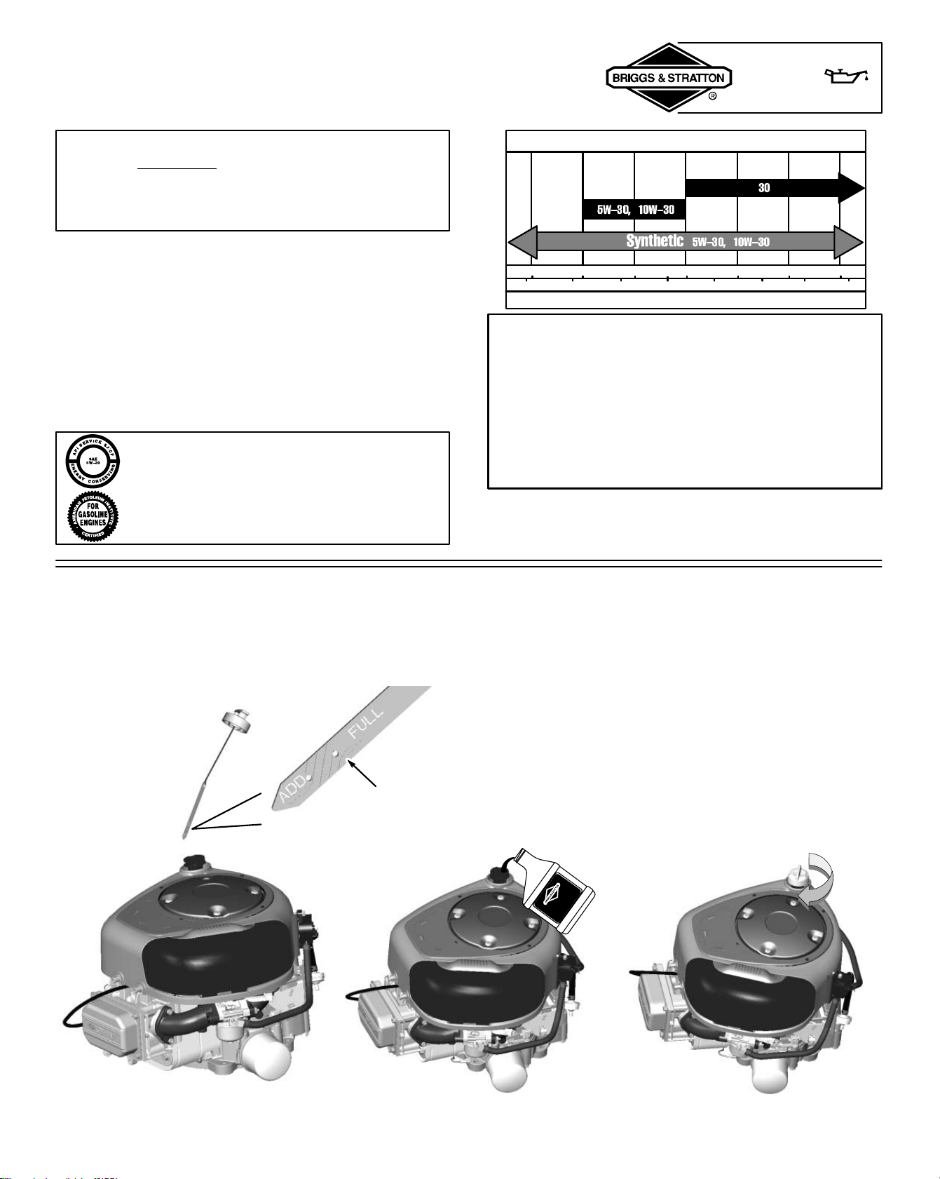
Document: - page 7 (Black)
Screen angle and frequency: 45.0000, 150.0000
7
OIL
275935
CAUTION: This engine is shipped from Briggs &
Stratton without oil. Check oil level before starting
engine. If you start the engine without oil, the engine
will be damaged beyond repair and will not be
covered under warranty.
OIL CAPACITY
Engine without oil filter holds approximately 1-1/2 quarts
(48 ounces; 1.4 liters).
TYPE OF OIL TO USE
• Use a high quality detergent oil classified “For Service
SF, SG, SH, SJ” or higher, such as Briggs & Stratton
30W, Part Number 100005 (20 oz) or 100028 (48 oz).
• Do not use special additives.
• Choose a viscosity according to the table opposite.
Note: Synthetic oil meeting ILSAC GF-2, API
certification mark and API service symbol
(shown at left) with “SJ/CF ENERGY CON-
SERVING” or higher, is an acceptable oil at all
temperatures. Use of synthetic oil does not
alter required oil change intervals.
°F
-20 0 20 40 60 80 100
°C
-30 -20 -10 0 10 20 30 40
STARTING TEMPERATURE RANGE ANTICIPATED BEFORE NEXT OIL CHANGE
*
**
32
* CAUTION: Air cooled engines run hotter than
automotive engines. The use of non-synthetic
multi-viscosity oils (5W-30, 10W-30, etc.) in
temperatures above 40° F (4° C) will result in higher
than normal oil consumption. When using a
multi-viscosity oil, check oil level more frequently.
** CAUTION: SAE 30 oil, if used below 40° F (4° C), will
result in hard starting and possible engine bore
damage due to inadequate lubrication.
SAE Viscosity Grades
CHECKING AND ADDING OIL
• Check oil level before starting the engine.
• Check level daily, or after every eight (8) hours.
• Keep oil level at FULL.
• Do not overfill.
[1] Place engine level and clean around oil fill area.
[2] Remove dipstick and wipe clean with cloth.
[3] Replace and tighten dipstick. Remove and check oil level.
[4] Oil level should be at FULL line on dipstick.
[5] If needed, add oil slowly - recheck. Do not over fill.
[6] Replace and tighten dipstick.
Document: - page 8 (Black)
Screen angle and frequency: 45.0000, 150.0000
8
[1] Remove cap. Fill tank to approximately 1-1/2
inches below top of neck to allow for fuel
expansion. Be careful not to overfill.
Briggs & Stratton Smart-fill) Fuel Can fills to
the correct level and automatically shuts off,
reducing spills and emissions.
[2] Replace cap before starting.
FUEL
TYPE OF FUEL TO USE
• Use clean, fresh, regular unleaded gasoline with a
minimum of 85 octane. Fresh fuel prevents gum from
forming in the fuel system or on essential carburetor parts.
Purchase fuel in quantity that can be used within 30 days.
• Do not use gasoline which contains Methanol.
• Do not mix oil with gasoline.
• For engine protection use Briggs & Stratton Gasoline
Additive available from your Authorized Briggs &
Stratton Dealer (P/N 5041 or single use pouch).
• The gasoline engine is certified to operate on gasoline.
Exhaust Emission Control System: EM (Engine
Modifications).
• Turn engine OFF and let engine cool at least
2 minutes before removing gas cap.
• Fill fuel tank outdoors or in well-ventilated
area.
• Keep gasoline away from sparks, open
flames, pilot lights, heat, and other ignition
sources.
• If fuel spills, wait until it evaporates before
starting engine.
CAUTION: Some fuels, called oxygenated or
reformulated gasoline, are gasoline blended with
alcohols or ethers. Excessive amounts of these
blends can damage the fuel system or cause
performance problems. If any undesirable operat-
ing symptoms occur, use gasoline with a lower
percentage of alcohol or ether.
GASOLINE POWERED ENGINES
NATURAL / LIQUID PROPANE GAS
POWERED ENGINES
• Use clean, dry fuel, free of moisture or any particulate
material. Using fuels outside the following recom-
mended values may cause performance problems.
• In engines set up to run on LPG, commercial grade
HD5 LPG is recommended. Recommended fuel
composition is fuel with a minimum fuel energy of
2500 BTU’s/ft
3
with maximum propylene content of
5% and butane and heavier gas content of 2.5% and
minimum propane content of 90%.
• NG or LPG engines are certified to operate on natural
or liquid propane gas.
The equipment on which this engine is
mounted is equipped with an automatic
safety gas “fuel lock-off” valve. DO
NOT operate the equipment if the “fuel
lock-off” valve is missing or
inoperative.
WARNING
ADDING FUEL
GASOLINE POWERED ENGINES
• Read the operating instructions supplied by the
equipment manufacturer for information on refueling
natural or LP gas engine.
NATURAL / LIQUID PROPANE GAS
POWERED ENGINES
WARNING
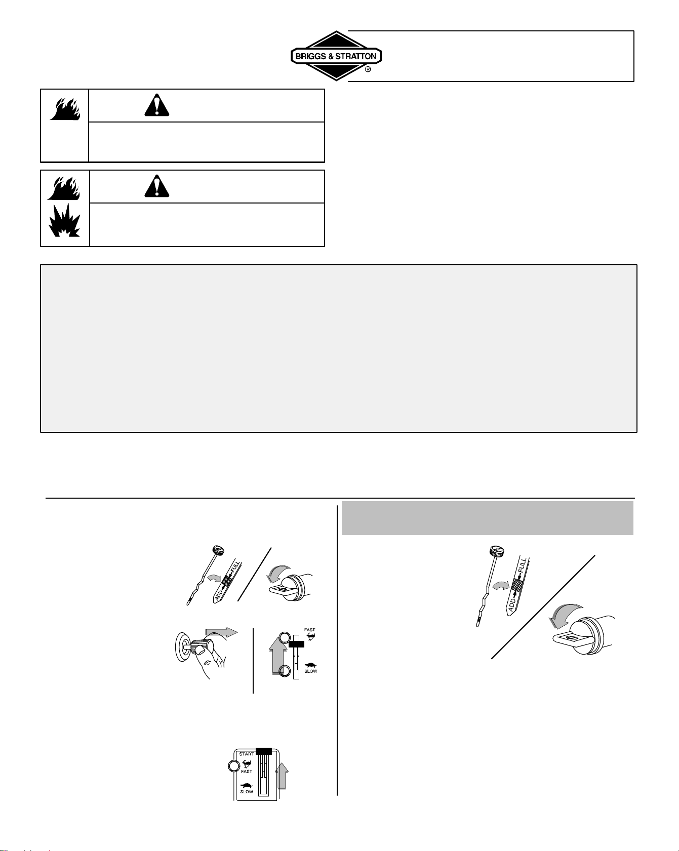
Document: - page 9 (Black)
Screen angle and frequency: 45.0000, 150.0000
9
STARTING
WARNING
• Do not use pressurized starting fluids.
• Vapors are flammable.
WARNING
• DO NOT start engine with air filter or
cover not properly installed. Serious injury
or death could result from backfire.
OIL PRESSURE SWITCH
If engine is equipped with an oil pressure switch, the switch
will either activate a warning light or stop the engine when
the engine runs low on oil. (Read the operating instructions
supplied by the equipment manufacturer to determine
which way your engine is equipped because the equipment
manufacturer supplies the oil pressure gauge.) See OIL
PRESSURE on page 12 for oil filling instructions.
♦ Store and fuel equipment in level position.
♦ Use fresh fuel. (See Fuel.)
♦ Use correct type of oil for expected starting
temperature. (See Oil.)
♦ Remove external equipment/engine loads. (See
equipment operating instructions.)
♦ Start lawn mower on hard surface or over
previously cut grass.
♦ Periodically remove grass buildup under mower
deck. (See Maintenance.)
♦ After engine has started, let it warm up several
seconds to several minutes, depending on outside
temperature.
♦ For maximum performance and life, operate
engine with choke in RUN and throttle in FAST.
STARTING AND OPERATING TIPS
BEFORE STARTING
[1] Check oil level.
[2] Open fuel valve.
NATURAL / LIQUID PROPANE GAS
POWERED ENGINES
[1] Check oil level.
[2] Open fuel
shut-off valve
(if equipped).
[3] If choke and
throttle controls
are separate,
move choke
control to
CHOKE. Move
throttle to FAST.
[4] If choke and
throttle are on the
same control,
move control to
CHOKE or
START.
Choke Throttle
Combined Choke/Throttle
control
1/4 TURN
GASOLINE POWERED ENGINES
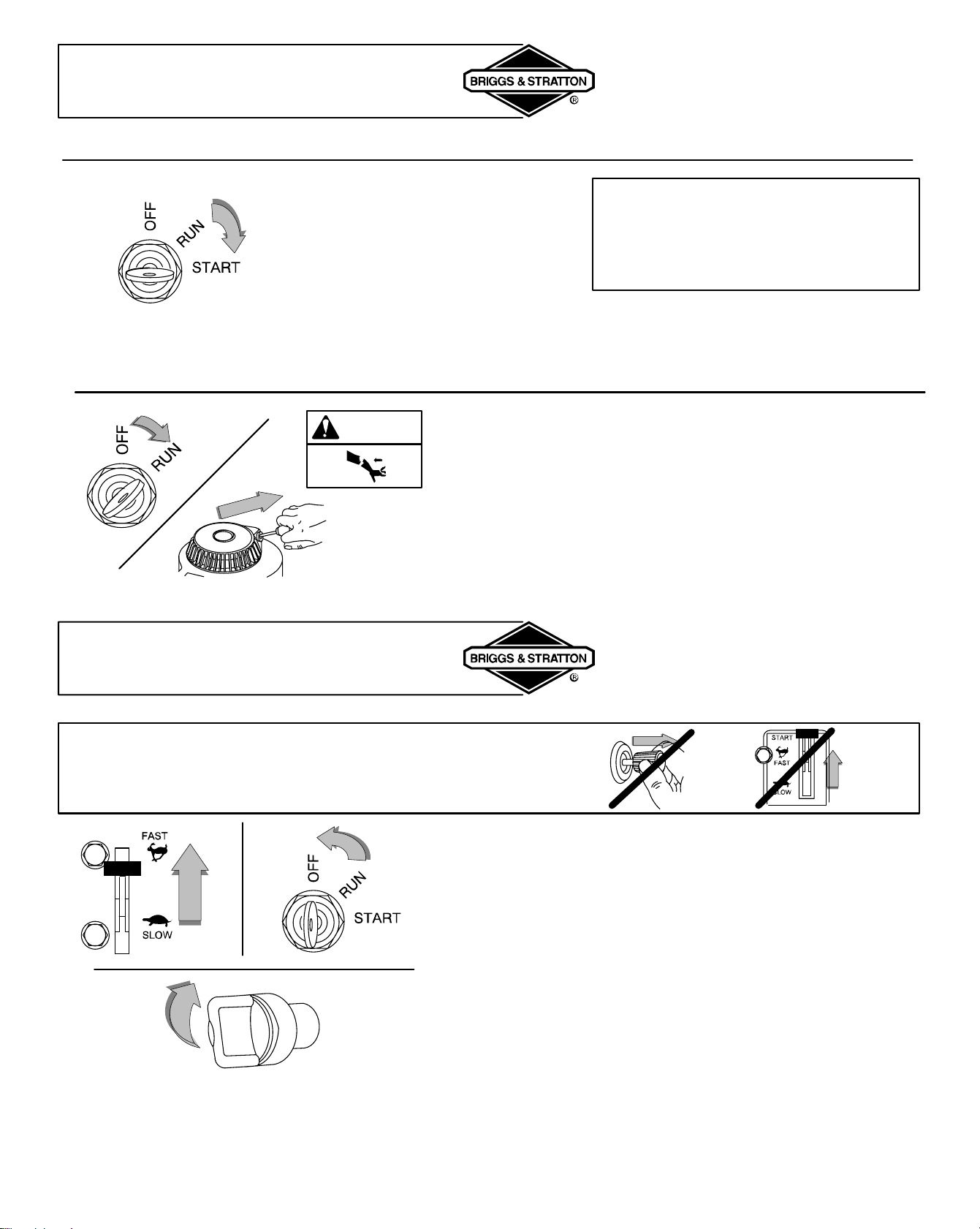
Document: - page 10 (Black)
Screen angle and frequency: 45.0000, 150.0000
10
STARTING
[1] Insert key and turn to START.
CAUTION:
To prolong starter life, use short starting
cycles (5 seconds maximum, then wait one
minute). Follow equipment manufacturer’s
recommendations for charging battery.
[2] Let engine warm up.
If choke equipped: Slowly adjust
toward RUN position. Wait until
engine runs smoothly before each
choke adjustment.
ELECTRIC (KEY) STARTER
WARNING
[3] Let engine warm up.
If choke equipped: Slowly adjust toward RUN position. Wait
until engine runs smoothly before each choke adjustment.
REWIND (MANUAL) STARTER (auxiliary)
[1] Insert key (if equipped) and turn to RUN.
[2] Grasp rope handle. Pull slowly until resistance is felt, then
pull rapidly to start engine and avoid kickback.
STOPPING
[1] With throttle in FAST, turn key to OFF.
[2] Remove key and store out of reach of children.
[3] Close fuel shut-off valve (if equipped).
1/4 TURN
CAUTION:
Do not stop engine by moving choke control to CHOKE.
Backfire, fire or engine damage could occur.
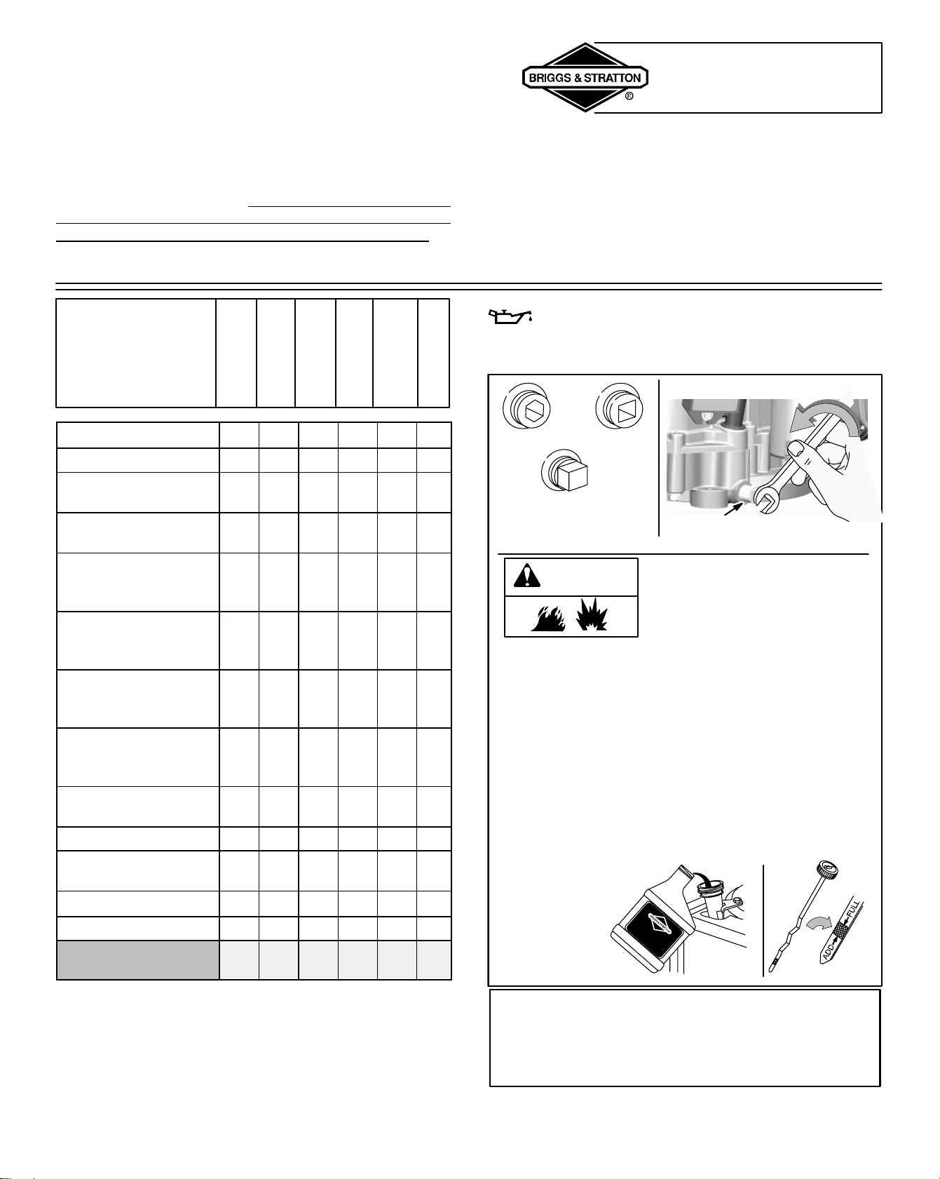
Document: - page 11 (Black)
Screen angle and frequency: 45.0000, 150.0000
11
MAINTENANCE
MAINTENANCE
Regular maintenance will improve the performance and
extend the life of the engine. See any Authorized Briggs &
Stratton Dealer for service. Use only genuine Briggs &
Stratton parts. Other parts may not perform as well,
may damage the engine, and may result in injury. In
addition, use of other parts may void your warranty.
EMISSION CONTROL
Maintenance, replacement or repair of the emission
control devices and systems may be performed by any
nonroad engine repair establishment or individual.
However, to obtain no charge repairs under the terms and
provisions of the Briggs & Stratton warranty statement, any
service or emission control part repair or replacement must
be performed by a factory authorized dealer.
Task
Perform task at hourly
or calendar interval,
whichever comes first.
Every 8 Hours
or Daily
25 Hours or
Every Season
50 Hours or
Every Season
100 Hours or
Every Season
Yearly
200 Hours or
Every Season
Check Oil Level
Change Oil *
Change oil filter
(if equipped)
*
Service air cleaner
pre-cleaner (if equipped)
**
Replace air cleaner car-
tridge (if not equipped
with pre-cleaner)
**
Replace air cleaner car-
tridge (if equipped with
pre-cleaner)
**
Clean Extended Life
Series air cleaner car-
tridge
**
Replace Extended Life
Series
air cleaner cartridge
**
Inspect spark arrester
(if equipped)
Replace spark plug
Replace in-line fuel filter
(if equipped)
Clean cooling system **
Check valve clearance
Check valve clearance
on NG / LPG Engines
* Change oil after first 5 to 8 hours of use, then every
50 hours or every season. Change oil every 25 hours
when operating the engine under heavy load or in high
temperatures.
** Clean more often under dusty conditions or when
airborne debris is present. Replace air cleaner parts, if
very dirty.
CHANGING OIL
[1] Place engine level.
[2] Disconnect spark plug
wire and keep away from
spark plug. Disconnect
battery (if equipped with
electric starter) at nega-
tive terminal.
[3] With engine OFF but still warm remove oil drain
plug and drain oil into appropriate receptacle.
[4] Reinstall drain plug. Remove dipstick.
[5] Fill to FULL mark on dipstick with new oil.
Do not overfill.
Note: Engine without oil filter holds approximately 1-1/2
quarts (48 ounces; 1.4 liters). Engine equipped with filter
holds approximately 1-3/4 quarts (56 ounces; 1.7 liters).
[6] Replace dipstick.
OIL DRAIN
PLUG
TO REMOVE
Typical drain
plugs
7/16” PIPE
5/16” HEX
3/8” SQUARE
WARNING
CAUTION: Used oil is a hazardous waste product.
Dispose of used oil properly. Do not discard with
household waste. Check with your local authorities,
service center, or dealer for safe disposal/recycling
facilities.
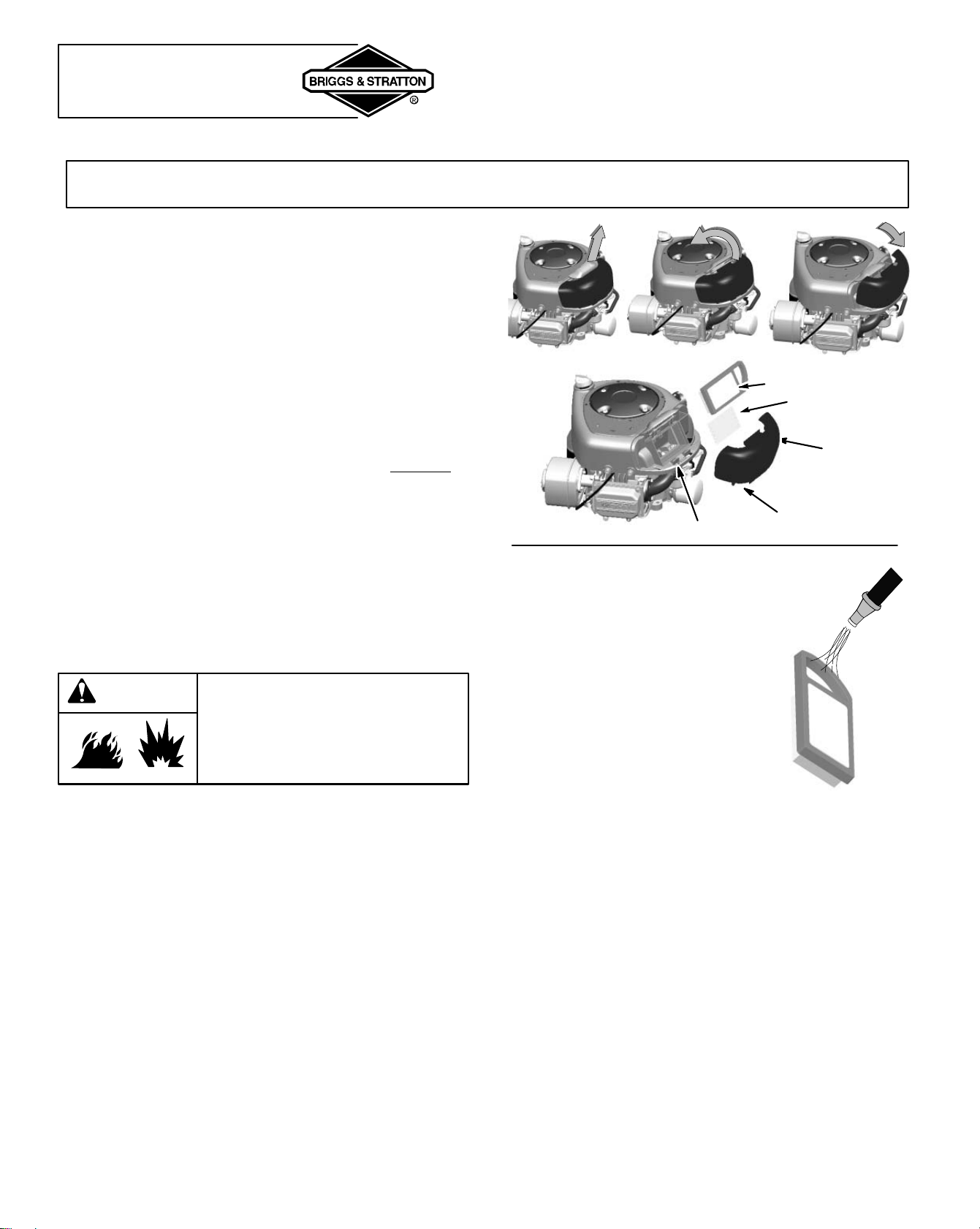
Document: - page 12 (Black)
Screen angle and frequency: 45.0000, 150.0000
12
MAINTENANCE
AIR CLEANER
CAUTION: Do not use pressurized air or solvents to clean cartridge. Pressurized air can damage cartridge;
solvents will dissolve cartridge.
FLAT AIR CLEANER REMOVAL/ INSTALLATION
[1] Pull up on air cleaner cover handle, and rotate toward
engine.
[2] Remove air cleaner cover.
[3] Carefully lift air cleaner cartridge and pre-cleaner, if
equipped, from blower housing.
Note: To clean pre-cleaner, wash in soapy water. Squeeze
dry in a clean cloth. DO NOT OIL.
[4] Clean base of air cleaner cartridge area carefully to
prevent debris from entering engine.
[5] Place air cleaner pre-cleaner, if equipped, and cartridge
into blower housing. Cartridge must fit securely in base.
[6] Align tabs on cover with slots of blower housing and
replace cover.
[7] Hook handle and close cover.
If filters, or covers are not installed
correctly serious injury or death
could result from backfire. Do not
attempt to start your engine with
them removed.
WARNING
COVER
PRE-CLEANER
(if equipped)
TABS
EXTENDED LIFE SERIESE CARTRIDGE ONLY
This filter, IF STAMPED
‘WASHABLE’, can be washed
with warm water and mild
soap.
IMPORTANT: Rinse in tap
water with SCREEN side up
allowing dirt and debris to filter
out.
Leave filter to dry overnight
before reinstalling.
CARTRIDGE
SLOTS
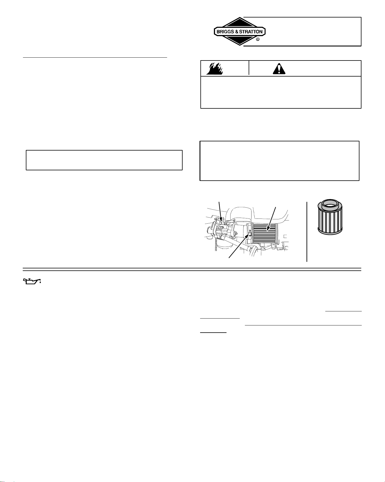
Document: - page 13 (Black)
Screen angle and frequency: 45.0000, 150.0000
13
MAINTENANCE
HIGH FLOW AIR CLEANER MAINTENANCE
Perform this maintenance every 25 hours or every season,
clean more often under dusty conditions or when airborne
debris is present. This filter is made of cotton, which is
different from a standard paper filter, therefore it MUST be
oiled.
[1] Remove clamp and pull air cleaner from intake
manifold.
[2] Remove as much dirt from the filter as possible.
[3] Using the High Flow Air Filter Cleaner Kit, Briggs &
Stratton part no. 5089D, spray the filter with cleaner.
Allow the solution to soak in to the filter for about 15
minutes.
CAUTION: Never use strong detergents, high
pressure water, or gasoline to clean this filter.
[4] Rinse the filter with warm water, inside first and then
outside. (Let the water run from the clean side to the
dirty side.)
[5] Allow the filter to dry completely. It is best to allow the
filter to dry naturally. Don’t use heat, this might shrink
the cotton.
[6] Use only air filter oil, such as the oil included in the
cleaning kit (P/N 5089D), to re-oil the filter.
WARNING
Never use motor oil, transmission fluid, WD40, or other
oils. Failure to follow instructions can cause fires
resulting in death or serious injury. Use only air filter oil
designed specifically for air filters.
[7] Spray the filter with oil, or pour small amount onto
each pleat and allow filter to stand for 20 minutes. The
filter is correctly oiled when the cotton changes from
white to the color of the oil.
CAUTION: DO NOT over-oil air filter, it will interfere
with engine performance and may cause engine
damage. If the filter is placed on cardboard for 10
minutes and leaves a stain, it is over oiled. Wash/clean
and re-oil per above instructions.
[8] Re-install air filter.
CARBURETOR
CLAMP
HIGH FLOW
AIR FILTER
FILTER
P/N 698973
OIL FILTER (IF EQUIPPED)
Replace oil filter after every 100 hours of operation.
[1] Drain engine oil and remove oil filter.
[2] Before installing new filter, lightly oil filter gasket with
fresh, clean engine oil.
[3] Screw filter on by hand until gasket contacts oil filter
adapter. Tighten 1/2 to 3/4 turn more.
[4] Add fresh oil. Fill to FULL line on dipstick.
[5] Start and run engine at idle to check for oil leaks.
[6] Stop engine. Recheck oil level and add oil if required.
OIL PRESSURE
If oil pressure drops too low, an oil pressure switch (if
engine is equipped) will either activate a warning light or
stop the engine. Check oil level with dipstick. If oil level is
between ADD and FULL mark on dipstick, Do not try to
restart engine. Contact an Authorized Briggs & Stratton
Service Dealer. Do not operate engine until oil pressure is
corrected.
If oil level is below ADD mark on dipstick, add oil to bring
level to FULL mark. Restart engine and check oil pressure.
If pressure is normal, continue to operate engine.
Note: Oil pressure gauge, if engine is equipped, is supplied
by manufacturer of equipment.
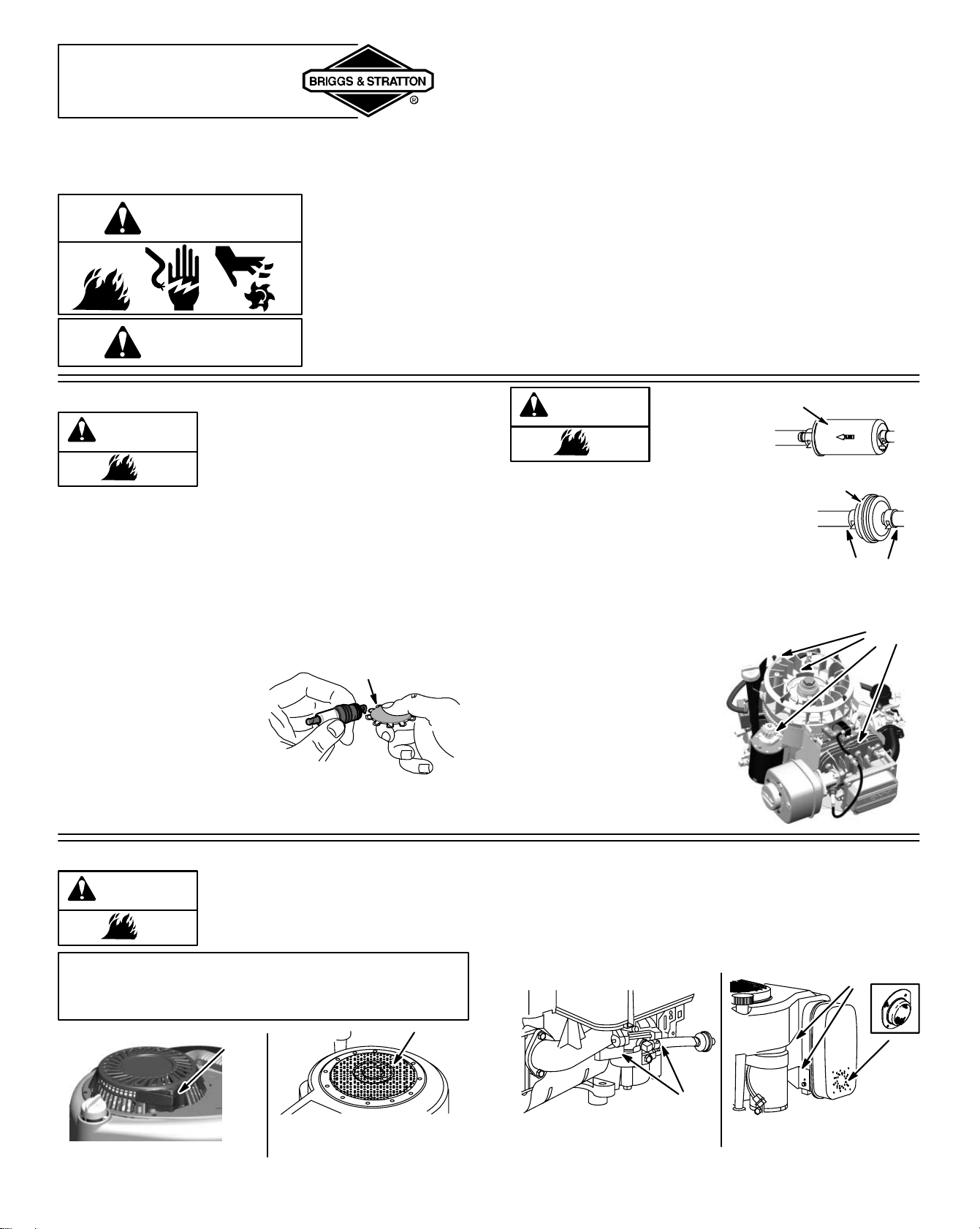
Document: - page 14 (Black)
Screen angle and frequency: 45.0000, 150.0000
14
MAINTENANCE
ENGINE AND ENGINE PARTS
We recommend that you see an authorized Briggs & Stratton Service Dealer for all maintenance and service of the engine
and engine parts. Use only genuine Briggs & Stratton parts.
WARNING
If you perform any maintenance on the engine, first disconnect the spark plug wire
from the spark plug, and disconnect the battery at the negative terminal (electric
starter engines only) to prevent unintentional sparking. Unintentional sparking can
result in fire or electric shock. Unintentional start-up can result in entanglement,
traumatic amputation or laceration. Use only correct tools.
WARNING
• Do not strike the flywheel with a hammer or hard object because the flywheel may
later shatter during operation.
• Do not tamper with governor spring, links or other parts to increase engine speed.
Replacement parts for the muffler
must be the same and installed in the
same position as the original parts,
otherwise fire can occur.
WARNING
If muffler is equipped with spark arrester screen, remove
screen for inspection. Replace screen if damaged or
plugged.
MUFFLER
SPARK PLUG
Use only Briggs & Stratton Spark Tester (part number
19368) to check for spark.
Note: In some areas, local
law requires using resistor
spark plug to suppress igni-
tion signals. If this engine
was originally equipped
with resistor spark plug,
use same type for replace-
ment.
.030” (0.76 mm)
WIRE GAGE
REPLACE FUEL FILTER (if equipped)
WARNING
EXTENDED LIFE SERIES FUEL FILTER
PART NO. 695666 OR 5070
(WITH FUEL PUMP)
Drain fuel tank or close
fuel shut-off valve before
replacing fuel filter.
Otherwise, fuel can leak
out, creating a fire/ex-
plosion hazard.
STANDARD FUEL FILTER
FUEL HOSE
CLAMPS
PART NO. 298090 OR 5018
(WITHOUT FUEL PUMP)
PART NO. 394358
(WITH FUEL PUMP)
Debris may clog the en-
gine’s air cooling system.
Remove blower housing
and clean area shown to
prevent overheating and
engine damage.
AIR COOLING SYSTEM
CLEAN OUT CHAFF AND
DEBRIS
CLEANING DEBRIS
Engine parts should be kept clean to
reduce the risk of overheating and
ignition of accumulated debris. This is
especially important if cutting tall grass.
WARNING
CAUTION: Do not use water to clean engine parts.
Water could contaminate fuel system. Use a brush
or dry cloth.
Finger Guard
CLEAN
CLEAN
Rotating Screen
Daily or before every use, clean grass, chaff or accumu-
lated debris from engine. Keep linkage, spring and
controls clean. Keep area around and behind muffler free
of any combustible debris.
Linkage, Springs,
Controls
CLEAN
CLEAN
Muffler,
Spark Arrester
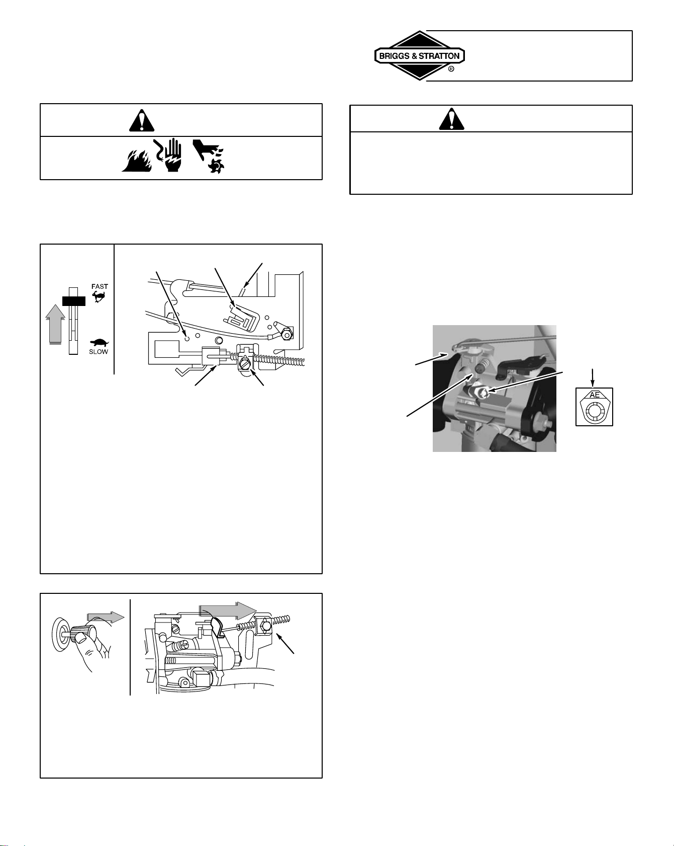
Document: - page 15 (Black)
Screen angle and frequency: 45.0000, 150.0000
15
ADJUSTMENTS
CONTROL ADJUSTMENTS
WARNING
TO ADJUST REMOTE THROTTLE
If the engine does not start or if it runs roughly, the remote
throttle control may need adjustment. See your authorized
Briggs & Stratton dealer or follow the instructions below.
[1] Move remote throttle control to FAST position.
[2] Hole in governor control lever (located just behind
governor control plate) must align with hole in
governor control plate, as illustrated above.
[3] If holes do not line up, loosen casing clamp screw
and then move governor control rack until it does.
[4] Tighten casing clamp screw.
[5] Check operation of throttle. Move throttle control to
STOP position.
[6] Governor control lever must make good contact with
stop switch (if equipped). Readjust if necessary.
HOLE IN
GOVERNOR
CONTROL PLATE
GOVERNOR
CONTROL LEVER
STOP
SWITCH
GOVERNOR CONTROL RACK CASING CLAMP SCREW
TO ADJUST REMOTE CHOKE
[1] Hold choke control to CHOKE or START position.
[2] Loosen casing clamp screw.
[3] Pull casing, wire and choke lever in direction of
arrow to end of travel.
[4] Tighten casing clamp screw.
CASING
CLAMP
SCREW
CARBURETOR ADJUSTMENT
WARNING
The manufacturer of the equipment on which this
engine is installed specifies top speed at which the
engine will be operated. DO NOT EXCEED this
speed.
Differences in fuel, temperature, altitude or load may require
minor carburetor adjustment. Air cleaner and its cover must
be assembled to carburetor before starting engine.
The carburetor on this engine is equipped with an idle
mixture valve with a limiter (see inset), which allows some
adjustment, and an idle speed adjustment screw.
TO ADJUST CARBURETOR
IDLE MIXTURE
VALVE
WITH LIMITER
CARBURETOR
THROTTLE
LEVER
IDLE
SPEED
SCREW
[1] To adjust idle speed, start engine and warm up
about 5 minutes.
[2] With engine running, place equipment throttle
control in SLOW position.
[3] Rotate carburetor throttle lever against the idle
speed screw and hold it. Turn idle speed screw to
obtain 1750 rpm (use a tachometer).
[4] Then rotate idle mixture valve full travel clockwise
and then counterclockwise.
Note: DO NOT remove limiter caps. DO NOT
force beyond limits.
[5] Then, position idle mixture valve in middle of travel.
[6] Check idle speed. Re-adjust to 1750 rpm, if needed.
[7] Move throttle control to FAST position. Engine
should accelerate smoothly. If it does not, adjust
idle mixture valve counterclockwise 1/8 turn.
Note: Engines operated at approximately 3000 to 5000 feet
(900 to 1500 meters) above sea level may require a high
altitude carburetor nozzle. If erratic performance is observed,
contact a Briggs & Stratton Authorized Service Dealer for cost
to install/purchase a high altitude carburetor nozzle.
Document: - page 16 (Black)
Screen angle and frequency: 45.0000, 150.0000
16
SERVICE & STORAGE
PARTIAL LIST OF BRIGGS & STRATTON PARTS
Models 280000, 310000 AVSE series
Extended Life SeriesE flat air cleaner cartridge 697153
(washable, no pre-cleaner required)
Extended Life SeriesE Maintenance Kit 5128. . . . . . . .
(Includes oil, A/C filter, spark plug, gas additive)
Flat air cleaner cartridge and pre-cleaner kit 5077. . . . .
Flat air cleaner cartridge 698083. . . . . . . . . . . . . . . . . . . .
Flat air cleaner pre-cleaner 697015. . . . . . . . . . . . . . . . . .
Maintenance Kit 5127. . . . . . . . . . . . . . . . . . . . . . . . . . . . . .
(Includes oil, A/C filter, spark plug, gas additive)
Model 210000 AVSE series
Flat air cleaner cartridge and pre-cleaner kit 5079. . . . .
Flat air cleaner cartridge 698413. . . . . . . . . . . . . . . . . . . .
Flat air cleaner pre-cleaner 697292. . . . . . . . . . . . . . . . . .
Maintenance Kit 5126. . . . . . . . . . . . . . . . . . . . . . . . . . . . . .
(Includes oil, A/C filter, spark plug, gas additive)
Oval air cleaner cartridge and pre-cleaner kit 5053. . . .
Oval air cleaner cartridge 496894. . . . . . . . . . . . . . . . . . . .
Oval air cleaner pre-cleaner 272403. . . . . . . . . . . . . . . . . .
High Flow Air Filter (cylinder) 698973. . . . . . . . . . . . . . . .
High Flow Air Filter Cleaning Kit 5089D. . . . . . . . . . . . . . .
Synthetic Oil (32 oz.) 100074. . . . . . . . . . . . . . . . . . . . . . .
Oil (20 oz.) 100005. . . . . . . . . . . . . . . . . . . . . . . . . . . . . . . .
Oil (48 oz.) 100028. . . . . . . . . . . . . . . . . . . . . . . . . . . . . . . .
Oil filter (3-1/2 in. long) 491056. . . . . . . . . . . . . . . . . . . . . .
Oil filter (2-1/4 in. long) 492932. . . . . . . . . . . . . . . . . . . . . .
Fuel filter 298090 -or- 5018. . . . . . . . . . . . . . . . . . . . . . . . .
(for engines without fuel pump installed)
Extended Life Series fuel filter 695666 -or- 5070. . . . . .
(for engines equipped with fuel pump)
Fuel filter 394358. . . . . . . . . . . . . . . . . . . . . . . . . . . . . . . . .
(for engines equipped with fuel pump)
Gas additive 5041. . . . . . . . . . . . . . . . . . . . . . . . . . . . . . . . .
Resistor spark plug 491055. . . . . . . . . . . . . . . . . . . . . . . . .
Long life platinum spark plug 5066. . . . . . . . . . . . . . . . . . .
(used on most OHV engines)
Spark plug wrench 89838 -or- 5023. . . . . . . . . . . . . . . . . . .
Spark tester 19368. . . . . . . . . . . . . . . . . . . . . . . . . . . . . . . .
Oil pump kit 5056. . . . . . . . . . . . . . . . . . . . . . . . . . . . . . . . .
(uses standard electric drill to remove oil from engine quickly)
SERVICE
See an Authorized Briggs & Stratton Service Dealer. Each
one carries a stock of Genuine Briggs & Stratton Parts and
is equipped with special service tools. Trained mechanics
assure expert repair service on all Briggs & Stratton
engines. Only dealers advertising as “Authorized Briggs &
Stratton” are required to meet Briggs & Stratton standards.
When you purchase equipment powered by a
Briggs & Stratton engine, you are assured of
highly skilled, reliable service at more than
30,000 Authorized Service Dealers
worldwide, including more than 5,000 Master
Service Technicians. Look for these signs
wherever Briggs & Stratton service is offered.
You may locate your nearest Authorized Briggs & Stratton
Service Dealer in our dealer locator map on our web site
or in the “Yellow Pages”
directory under “Engines, Gasoline” or “Gasoline
Engines,” or “Lawn Mowers” or similar category.
Note: Walking fingers logo and “Yellow Pages” are regis-
tered trademarks in various jurisdictions.
An illustrated shop manual includes
common specifications and detailed
information covering adjustment,
tune-up and repair of Briggs & Strat-
ton single cylinder, OHV, 4 cycle
engines. It is available for purchase
from an Authorized Briggs & Stratton
Service Dealer or you can order it
from the factory. Write:
Briggs & Stratton Corporation
Attn: Service Division
P. O. Box 1144
Milwaukee, WI 53201
Part No. 272147
STORAGE
Engines stored over 30 days need special attention.
[1] To prevent gum from forming in fuel system or on
essential carburetor parts:
a) if fuel tank contains oxygenated or reformulated
gasoline (gasoline blended with an alcohol or an
ether), run engine until it stops from lack of fuel, or b) if
fuel tank contains gasoline, either run engine until it
stops from lack of fuel, or add a gasoline additive to the
gas in the tank. (See parts list. Single – use pouches of
gas additive are available from your service dealer.) If
you use a gas additive, run the engine for several
minutes to circulate the additive through the carburetor.
Then, engine and fuel can be stored up to 24 months.
[2] While engine is still warm, change oil.
[3] Remove spark plug and pour about 1 oz. (30 ml) of
engine oil into cylinder. Replace spark plug and crank
slowly to distribute oil.
[4] Clean engine of surface debris, chaff or grass.
WARNING
[5] Store in a clean, dry area.
Do not store in same area
as a stove, furnace, water
heater, or other appliance
that uses a pilot light or
has a device that can
create a spark.

Document: - page 1 (Black)
Screen angle and frequency: 45.0000, 150.0000
17
LIMITED WARRANTY
Briggs & Stratton Corporation will repair or replace, free of charge, any part(s) of the engine that is defective in material or workmanship or both.
Transportation charges on parts submitted for repair or replacement under this warranty must be borne by purchaser. This warranty is effective for the
time periods and subject to the conditions stated below. For warranty service, find the nearest Authorized Service Dealer in our dealer locator map
at www.briggsandstratton.com
, or by calling 1-800-233-3723, or as listed in the ‘Yellow Pages’.
THERE IS NO OTHER EXPRESS WARRANTY. IMPLIED WARRANTIES, INCLUDING THOSE OF MERCHANTABILITY AND FITNESS FOR A
PARTICULAR PURPOSE, ARE LIMITED TO ONE YEAR FROM PURCHASE, OR TO THE EXTENT PERMITTED BY LAW ANY AND ALL IMPLIED
WARRANTIES ARE EXCLUDED. LIABILITY FOR INCIDENTAL OR CONSEQUENTIAL DAMAGES ARE EXCLUDED TO THE EXTENT
EXCLUSION IS PERMITTED BY LAW. Some states or countries do not allow limitations on how long an implied warranty lasts, and some states or
countries do not allow the exclusion or limitation of incidental or consequential damages, so the above limitation and exclusion may not apply to you.
This warranty gives you specific legal rights and you may also have other rights which vary from state to state and country to country.
r
(Sleeve Bore)
!"
(Kool Bore)
!# $
%&r
%!
%45
'
"
Commercial Use
2 years
90 days
1 year
Consumer Use
2 years
2 years
90 days
1 year
( )(
)*
1 year
* Note the following special warranty periods: 2 years for Classic engines in the European Union and Eastern European countries, for all consumer products in
the European Union, and for emission control systems on engines certified by EPA and CARB. 5 years for consumer use, 90 days for commercial use of Touch-N-
Mow starter on Quantum and Intek engines. Engines used in competitive racing or on commercial or rental tracks are not warrantied.
The warranty period begins on the date of purchase by the first retail consumer or commercial end user, and continues for the period of time stated in the table
above. “Consumer use” means personal residential household use by a retail consumer. “Commercial use” means all other uses, including use for commercial,
income producing or rental purposes. Once an engine has experienced commercial use, it shall thereafter be considered as a commercial use engine for pur-
poses of this warranty.
NO WARRANTY REGISTRATION IS NECESSARY TO OBTAIN WARRANTY ON BRIGGS & STRATTON PRODUCTS. SAVE YOUR PROOF OF PURCHASE
RECEIPT. IF YOU DO NOT PROVIDE PROOF OF THE INITIAL PURCHASE DATE AT THE TIME WARRANTY SERVICE IS REQUESTED, THE
MANUFACTURING DATE OF THE PRODUCT WILL BE USED TO DETERMINE THE WARRANTY PERIOD.
! "
#
$
#
! $
! %
&
' #
(
"
&
#
! "
# $!
! % !! ! " &
! ' %
) *+,-' ./' 0 *+& &1& +' 2,&
,+$3$2- +$33 &+&&,2 *+&
4 '
5. 6
7 -# #
5/ 8
! * 2 9:;)6
; * #
5# <=
+
6 ,$- 3+
'
+ ,
$
9 + %
>
8 8
5
8 ,8!
8 6 +
, $
? * 8
5.
6 + ,
$
< ' # "
# 8
@ # # #
%
" 8
): + 8 %
)) '
!"! !!
! !( )"" * + ,&
-!( + . !
/0 1"2 !
/" 32 /3 "2 /4
52 "&
( (

Document: - page 2 (Black)
Screen angle and frequency: 45.0000, 150.0000
18
! !'!! +,- . /! !" ! +,
. ( 0!& !"! "1 +(22 ,
&! !! 1& 1 & +#3 )/" 1 . 4!,
EMISSION CONTROL WARRANTY COVERAGE IS APPLICABLE TO CERTIFIED ENGINES PURCHASED IN CALIFORNIA IN 1995 AND THERE-
AFTER, WHICH ARE USED IN CALIFORNIA, AND TO CERTIFIED MODEL YEAR 1997 AND LATER ENGINES WHICH ARE PURCHASED AND
USED ELSEWHERE IN THE UNITED STATES (AND AFTER JANUARY 1, 2001 IN CANADA).
/! ( &! !! )/" 1 &
The California Air Resources Board (CARB), U.S.
EPA and B&S are pleased to explain the Emission
Control System Warranty on your model year
2002 and later small off-road engine (SORE). In
California, new small off-road engines must be de-
signed, built and equipped to meet the State’s
stringent anti-smog standards.
Elsewhere in the United States, new non-road,
spark-ignition engines certified for model year
1997 and later must meet similar standards set
forth by the U.S. EPA. B&S must warrant the emis-
sion control system on your engine for the periods
of time listed below, provided there has been no
abuse, neglect or improper maintenance of your
small off-road engine.
Your emission control system includes parts
such as the carburetor, air cleaner, ignition sys-
tem, muffler and catalytic converter. Also in-
cluded may be connectors and other emission
related assemblies.
Where a warrantable condition exists, B&S will
repair your small off-road engine at no cost to
you including diagnosis, parts and labor.
! &! !! )/" 1 !0
Small off-road engines are warranted relative to emission control parts defects for a period of two years, subject to provisions set forth below. If any
covered part on your engine is defective, the part will be repaired or replaced by B&S.
#3 1 '!4
As the small off-road engine owner, you are re-
sponsible for the performance of the required
maintenance listed in your Operating and Main-
tenance Instructions. B&S recommends that
you retain all your receipts covering mainte-
nance on your small off-road engine, but B&S
cannot deny warranty solely for the lack of re-
ceipts or for your failure to ensure the perfor-
mance of all scheduled maintenance.
As the small off-road engine owner, you should
however be aware that B&S may deny you war-
ranty coverage if your small off-road engine or a
part has failed due to abuse, neglect, improper
maintenance or unapproved modifications.
You are responsible for presenting your small
off-road engine to an Authorized B&S Service
Dealer as soon as a problem exists.
The undisputed warranty repairs should be
completed in a reasonable amount of time, not
to exceed 30 days.
If you have any questions regarding your war-
ranty rights and responsibilities, you should con-
tact a B&S Service Representative at
1-414-259-5262.
The emission warranty is a defects warranty.
Defects are judged on normal engine perfor-
mance. The warranty is not related to an in-use
emission test.
! &! !! )/" 1 !0!
The following are specific provisions relative to your Emission Control Defects Warranty Coverage. It is in addition to the B&S engine warranty for non-
regulated engines found in the Operating and Maintenance Instructions.
1. Warranted Parts
Coverage under this warranty extends only
to the parts listed below (the emission con-
trol systems parts) to the extent these parts
were present on the engine purchased.
a. Fuel Metering System
• Cold start enrichment system
• Carburetor and internal parts
• Fuel Pump
b. Air Induction System
• Air cleaner
• Intake manifold
c. Ignition System
• Spark plug(s)
• Magneto ignition system
d. Catalyst System
• Catalytic converter
• Exhaust manifold
• Air injection system, Pulse valve
e. Miscellaneous Items
• Vacuum, temperature, position,
time sensitive valves
and switches
• Connectors and assemblies
2. Length of Coverage
B&S warrants to the initial owner and each
subsequent purchaser that the Warranted
Parts shall be free from defects in materials
and workmanship which caused the failure
of the Warranted Parts for a period of two
years from the date the engine is delivered to
a retail purchaser.
3. No Charge
Repair or replacement of any Warranted
Part will be performed at no charge to the
owner, including diagnostic labor which
leads to the determination that a Warranted
Part is defective, if the diagnostic work is
performed at an Authorized B&S Service
Dealer. For emissions warranty service
contact your nearest Authorized B&S Ser-
vice Dealer as listed in the “Yellow Pages”
under “Engines, Gasoline,” “Gasoline En-
gines,” “Lawn Mowers,” or similar category.
4. Claims and Coverage Exclusions
Warranty claims shall be filed in accordance
with the provisions of the B&S Engine War-
ranty Policy. Warranty coverage shall be ex-
cluded for failures of Warranted Parts which
are not original B&S parts or because of
abuse, neglect or improper maintenance as
set forth in the B&S Engine Warranty Policy.
B&S is not liable to cover failures of War-
ranted Parts caused by the use of add-on,
non-original, or modified parts.
5. Maintenance
Any Warranted Part which is not scheduled
for replacement as required maintenance or
which is scheduled only for regular inspec-
tion to the effect of “repair or replace as nec-
essary” shall be warranted as to defects for
the warranty period. Any Warranted Part
which is scheduled for replacement as re-
quired maintenance shall be warranted as to
defects only for the period of time up to the
first scheduled replacement for that part. Any
replacement part that is equivalent in perfor-
mance and durability may be used in the per-
formance of any maintenance or repairs.
The owner is responsible for the perfor-
mance of all required maintenance, as de-
fined in the B&S Operating and Maintenance
Instructions.
6. Consequential Coverage
Coverage hereunder shall extend to the fail-
ure of any engine components caused by
the failure of any Warranted Part still under
warranty.
' / , , , & ! *A 84;?)?? 5, * *6
6,325,036
6,284,123
6,260,529
6,230,678
6,202,616
6,116,212
6,077,063
6,064,027
6,014,808
5,894,715
5,852,951
5,823,153
5,819,513
5,813,384
5,765,713
5,645,025
5,642,701
5,619,845
5,606,948
5,606,851
5,548,955
5,546,901
5,503,125
5,501,203
5,497,679
5,320,795
5,271,363
5,269,713
5,265,700
5,243,878
5,235,943
5,197,425
5,197,422
5,191,864
5,188,069
5,186,142
5,138,996
5,086,890
5,070,829
5,058,544
5,040,644
5,009,208
4,996,956
4,977,879
4,971,219
4,895,119
4,819,593
4,719,682
4,633,556
4,630,498
4,522,080
4,520,288
4,512,499
4,453,507
4,430,984 DES. 308,871
DES. 308,872
DES. 309,457
DES. 356,951
DES. 361,771
DES. 375,963

Document: - page 1 (Black)
Screen angle and frequency: 45.0000, 150.0000
! "# $%& ! %% ' %
! "#$%%! %%& !'
(# $# (' )**+ # , - ' .
# ('/ -0 !'" (# " )**1 # .
, - ' ## $# # 0 %# )
2, 344) "5
(% "# $%&
6 7 & &/ & 897 7 :8
55 % &; <= = >?8 97<8
8 < : 8? 3444 9 9 '5 6/
:= 8 < : @ 7A/ 7 99 7
= 5 = / := 8 < B
C 8 769 8? )**1 / : 7 8 8.
8 : 55 %5 & ; >?8 7D 97<.
8 : 8 9 8 89 77/ 6 6 CE
C/ 97 95
, >?8 7D 97<8 78 ?7 7C/ 6 B
/ >?8 / 7= 7: 7>5 78
77 ?7 9 B 985
> 7 B / &; 9 8 : 8 < 7
7/ ?7 8 F:5
%% "# ) $%&
8 < 7 9679 ?7 >?8 7D.
97<8 9 3 / E = 7 9 775 8.
?7 : 8 7: 7 967/ 99
879 &;5
'% %
9 8 < / : @ C : B =97
9 : 8 9 5 &; : 78.
8 7: A 7: := : 8 < .
/ 8 &; 6 C7 A 96 : :
97<97 88 5
9 8 < / : :G @ 689 &; 6
< 7 9679 : 8 : 8 B
8 C6/ 97/ 77 867 :95
, :G C9 : 8 < B 9 9 &;
D : C?85 9 : @ 7899
9 C : =79 H4 E5
: :G :8 B : / : C9/ :G
788 :7 9 :7 &; 89 )I)I3+*+3J35
>?8 97<8 7 96795 967.
9 E9 67 8 85 9 B
97<8 6679 B 95
( "# $%&
77 976 :8 B : >?8 7D 97<85 B &; 8 989 7
8 5
)5 #
7: 7 ?7 9 77
>?8 7D 97<8 8 K 7 ?7 9 9
8 88 7<5
5 >?8 7C
• >?8 7<8 98 B 6
• C
• %8 B 7
C5 >?8 7
• ( B
• C 8
75 >?8
• & 8
• >?8 8 9789
5 >?8 7>
• : 7>
• 7 97<8
• >?8 E7 B
5 ?7 9 >?8 7< 89
• 9/ 89/ 5
• 7 8C5
35 (%
&;
9 7< C9 ?7 .
=8 :7 8? 6C7 7 967.
9 ?7 9 = B B 8.
99 :9 B 7<5
H5 7 (
9 878 ?7 6679 7
6 9/ 7 6 8 F: 7 6 98.
?7 967/ 7 B 7 7 6679
7<G 9 9 &;5 % : >?8 97<8/ 788.
G :7 9 9 &; 7< 9 E
: 79 C 8 B 7/ 79 85
I5 978 =7 7:5
978 : @ 7899 77 :7
&;5 7: 9679 ?7
?7 &; 7 C/ 97 95
&; 7: 9679 ?7 6 CE
E/ 99 869 ?7 ?7 &; 5
+5
?7 879 88 8 .
69 8 7 9? 8 LM9
87 97MN 7 9679 9 5
?7 69 878 .
7 9679 8 9 8 : E
8 878 9: 7 ?75 ?7 878 9:
687 C9 @ 9 95 9
C =97 96 8 7
&; 95
J5 : 7
7: 77 9 B 9679 78 8 79
9679 8 ?7 7: 7
:5
* % '% $% $+,(+ $ $%- $%
8 769 768 = 8 98 6 7 & & 3/ : 667< 68 77 9 C9 >?8
98 " 5 68 9 9 9 8 & ; 5 9 8 8 77 7675
% '% $% 8C < 8 8 769 768 = 8 98 9: 9 9
8 9 5 79 : 9MO
.%% 8 769 768 )3+ < 85
+% 8 769 768 3+4 < 85
% 8 769 768 +44 < 85
% =8/ 8? 9 : 34 B 3+ < 95 % 79/ % '% $% 8 79 89 7 >
9: B )4 B )3 5
$ 8C 97 : 6 98 79 976 85 % $ C/ 8 975 68 9
68 < 9 985
/ 0
1 2333 * % % $% %-
? )
E 3444/ 7 8 &; 769 768 = 8 :8 98 :8 %7 7> % %< 35 %
8 769 %< 3/ 9 7689 98 89 9 8C < 8 7 8 6995 %
8 67 8 33+ 77/ 79 P )3+ </ & P 3+4 < P +44 <5 % 8 33+ 77 / 79 P 3+4 </ & P +44 < P )444 <5
878 8 8? 9 3)4444 HII 77/ 3Q4444 IJ+ 77/ H)4444 +4) 775
% %- $%
- * %4O
CE MOTEUR EST CONFORME AUX NORMES
ANTIPOLLUTION 2000 – 2001 DE CALIFORNIE
POUR LES PETITS MOTEURS HORS ROUTE ET
AUX NORMES ENVIRONNEMENTALES
AMÉRICAINES (EPA PHASE 2) POUR LES
PETITS MOTEURS HORS ROUTE. CONSULTEZ
LE MANUEL DU PROPRIÉTAIRE POUR LES
SPÉCIFICATIONS, L’ENTRETIEN ET LES
AJUSTEMENTS. CONFORME À LA PÉRIODE
D’ÉMISSION EPA : CATÉGORIE : C
FAMILLE YBSXS.3192VA 274812
INFORMATIONS IMPORTANTES
CORPORATION BRIGGS & STRATTON


MANUFACTURER’S LIMITED WARRANTY FOR:
The limited warranty set forth below is given by Cub Cadet
LLC with respect to new merchandise purchased and used in
the United States, its possessions and territories.
“Cub Cadet” warrants this product against defects in material
and workmanship for a period of two (2) years commencing
on the date of original purchase and will, at its option, repair or
replace, free of charge, any part found to be defective in
materials or workmanship. This limited warranty shall only
apply if this product has been operated and maintained in
accordance with the Operator’s Manual furnished with the
product, and has not been subject to misuse, abuse,
commercial use, neglect, accident, improper maintenance,
alteration, vandalism, theft, fire, water, or damage because of
other peril or natural disaster. Damage resulting from the
installation or use of any part, accessory or attachment not
approved by Cub Cadet for use with the product(s) covered
by this manual will void your warranty as to any resulting
damage.
Normal wear parts or components thereof are subject to
separate terms as follows: All normal wear parts or
component failures will be covered on the product for a period
of 30 days regardless of cause. After 30 days, but within the
two year period, normal wear part failures will be covered
ONLY IF caused by defects in materials or workmanship of
OTHER component parts. Normal wear parts and
components include, but are not limited to: batteries, belts,
blades, blade adapters, grass bags, rider deck wheels, seats,
snow thrower skid shoes, shave plates, auger spiral rubber,
and tires.
HOW TO OBTAIN SERVICE: Warranty service is available,
WITH PROOF OF PURCHASE, through your local authorized
service dealer. To locate the dealer in your area, check your
Yellow Pages, or contact Cub Cadet LLC at P.O. Box 361131,
Cleveland, Ohio 44136-0019, or call 1-877-282-8684, or log
on to our Web site at www.cubcadet.com.
This limited warranty does not provide coverage in the
following cases:
a. The engine or component parts thereof. These items
may carry a separate manufacturer’s warranty. Refer
to applicable manufacturer’s warranty for terms and
conditions.
b. Log splitter pumps, valves, and cylinders have a sepa
rate one year warranty.
c. Routine maintenance items such as lubricants, filters,
blade sharpening, tune-ups, brake adjustments, clutch
adjustments, deck adjustments, and normal
deterioration of the exterior finish due to use or
exposure.
d. Cub Cadet does not extend any warranty for products
sold or exported outside of the United States, its
possesions and territories, except those sold through
Cub Cadet’s authorized channels of export
distribution.
e. Replacement parts that are not genuine Cub Cadet
parts.
f. Service completed by someone other than an
authorized service dealer.
g. Transportation charges and service calls.
No implied warranty, including any implied warranty of
merchantability of fitness for a particular purpose,
applies after the applicable period of express written
warranty above as to the parts as identified. No other
express warranty, whether written or oral, except as
mentioned above, given by any person or entity,
including a dealer or retailer, with respect to any product,
shall bind Cub Cadet. During the period of the warranty,
the exclusive remedy is repair or replacement of the
product as set forth above.
The provisions as set forth in this warranty provide the
sole and exclusive remedy arising from the sale. Cub
Cadet shall not be liable for incidental or consequential
loss or damage including, without limitation, expenses
incurred for substitute or replacement lawn care services
or for rental expenses to temporarily replace a warranted
product.
Some states do not allow the exclusion or limitation of
incidental or consequential damages, or limitations on how
long an implied warranty lasts, so the above exclusions or
limitations may not apply to you.
In no event shall recovery of any kind be greater than the
amount of the purchase price of the product sold. Alteration
of safety features of the product shall void this warranty.
You assume the risk and liability for loss, damage, or injury to
you and your property and/or to others and their property
arising out of the misuse or inability to use the product.
This limited warranty shall not extend to anyone other than the
original purchaser or to the person for whom it was purchased
as a gift.
HOW STATE LAW RELATES TO THIS WARRANTY: This
limited warranty gives you specific legal rights, and you may
also have other rights which vary from state to state.
IMPORTANT:
Owner must present Original Proof of
Purchase to obtain warranty coverage.
Cub Cadet LLC, P.O. BOX 361131 CLEVELAND, OHIO 44136-0019; Phone: 1-877-282-8684