CUB CADET LLC, P.O. BOX 361131 CLEVELAND, OHIO 44136-0019
Printed In USA
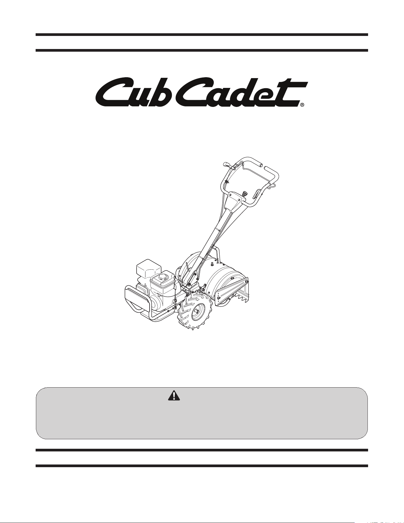
OperatOr’s Manual
Safe Operation Practices • Set-Up • Operation • Maintenance • Service • Troubleshooting • Warranty
WARNING
READ AND FOLLOW ALL SAFETY RULES AND INSTRUCTIONS IN THIS MANUAL
BEFORE ATTEMPTING TO OPERATE THIS MACHINE.
FAILURE TO COMPLY WITH THESE INSTRUCTIONS MAY RESULT IN PERSONAL INJURY.
Rear Tine Tiller — RT-75
Form No. 769-09425
(October 10, 2013)

To The Owner
1
2
Safe Operation Practices ........................................ 3
Assembly & Set-Up .................................................. 7
Controls & Features ................................................10
Operation ................................................................12
Maintenance & Adjustments .................................14
Service .....................................................................16
Troubleshooting .....................................................18
Replacement Parts .................................................19
Warranty ................................................................ 20
Table of Contents
Product Registration and Customer Support
Please register your product on our website, www.cubcadet.com.
If you have difficulty assembling this product or have any questions regarding the controls, operation, or maintenance of
this machine, you can seek help from the experts. Choose from the options below:
◊ Visit us on the web at www.cubcadet.com
See How-to Maintenance and Parts Installation Videos at www.cubcadet.com/tutorials
◊ Call a Customer Support Representative at (800) 965-4CUB
◊ Locate your nearest Cub Cadet Dealer at (877) 282-8684
◊ Write to Cub Cadet LLC • P.O. Box 361131 • Cleveland, OH • 44136-0019
Thank you for purchasing a Cub Cadet garden tiller. It was
carefully engineered to provide excellent performance when
properly operated and maintained.
Please read this entire manual prior to operating the equipment.
It instructs you how to safely and easily set up, operate and
maintain your machine. Please be sure that you, and any other
persons who will operate the machine, carefully follow the
recommended safety practices at all times. Failure to do so could
result in personal injury or property damage.
All information in this manual is relative to the most recent
product information available at the time of printing. Review
this manual frequently to familiarize yourself with the machine,
its features and operation. Please be aware that this Operator’s
Manual may cover a range of product specifications for various
models. Characteristics and features discussed and/or illustrated
in this manual may not be applicable to all models. We reserve
the right to change product specifications, designs and
equipment without notice and without incurring obligation.
If applicable, the power testing information used to establish
the power rating of the engine equipped on this machine can be
found at www.opei.org or the engine manufacturer’s web site.
If you have any problems or questions concerning the machine,
phone your local Cub Cadet dealer or contact us directly. Cub
Cadet’s Customer Support telephone numbers, website address
and mailing address can be found on this page. We want to
ensure your complete satisfaction at all times.
Throughout this manual, all references to right and left side of the
machine are observed from the operating position
The engine manufacturer is responsible for all engine-related
issues with regards to performance, power-rating, specifications,
warranty and service. Please refer to the engine manufacturer’s
Owner’s/Operator’s Manual, packed separately with your
machine, for more information.
Thank You
Record Product Information
Before setting up and operating your new equipment, please
locate the model plate on the equipment and record the
information in the provided area to the right. You can locate the
model plate by standing at the operator’s position and looking
down at the rear of the deck. This information will be necessary,
should you seek technical support via our web site or with your
local Cub Cadet dealer.
Model NuMber
Serial NuMber
Important Safe Operation Practices
2
3
Training
1. Read, understand, and follow all instructions on the
machine and in the manual(s) before attempting to
assemble and operate. Keep this manual in a safe place for
future and regular reference and for ordering replacement
parts.
2. Be familiar with all controls and their proper operation.
Know how to stop the machine and disengage them
quickly.
3. Never allow children under 14 years of age to operate this
machine. Children 14 and over should read and understand
the instructions and safe operation practices in this manual
and on the machine and be trained and supervised by an
adult.
4. Never allow adults to operate this machine without proper
instruction.
5. Keep the area of operation clear of all persons, particularly
small children and pets. Stop machine if anyone enters the
area.
Preparation
1. Thoroughly inspect the area where the equipment is to
be used. Remove all stones, sticks, wire, and other foreign
objects which could be tripped over and cause personal
injury.
2. Wear sturdy, rough-soled work shoes and close fitting
slacks and shirt. Loose fitting clothes or jewelry can be
caught in moving parts. Never operate this machine in bare
feet or sandals.
3. Disengage clutch levers and shift (if provided) into neutral
(“N”) before starting the engine.
4. Never leave this machine unattended with the engine
running.
5. Never attempt to make any adjustments while engine is
running, except where specifically recommended in the
operator’s manual.
Safe Handling of Gasoline:
To avoid personal injury or property damage use extreme care
in handling gasoline. Gasoline is extremely flammable and the
vapors are explosive. Serious personal injury can occur when
gasoline is spilled on yourself or your clothes which can ignite.
Wash your skin and change clothes immediately.
a. Use only an approved gasoline container.
b. Never fill containers inside a vehicle or on a truck
or trailer bed with a plastic liner. Always place
containers on the ground away from your vehicle
before filling.
WARNING! This symbol points out important safety instructions which, if not followed,
could endanger the personal safety and/or property of yourself and others. Read and follow
all instructions in this manual before attempting to operate this machine. Failure to comply
with these instructions may result in personal injury.
When you see this symbol. HEED ITS WARNING!
DANGER! This machine was built to be operated according to the safe operation practices in
this manual. As with any type of power equipment, carelessness or error on the part of the
operator can result in serious injury. This machine is capable of amputating fingers, hands,
toes and feet. Failure to observe the following safety instructions could result in serious
injury or death.
CALIFORNIA PROPOSITION 65
WARNING! Engine Exhaust, some of its constituents, and certain vehicle components
contain or emit chemicals known to State of California to cause cancer and birth defects
or other reproductive harm.
WARNING! Battery posts, terminals, and related accessories contain lead and lead
compounds, chemicals known to the State of California to cause cancer and reproductive
harm. Wash hands after handling

Section 2 — important Safe operation practiceS4
11. After striking a foreign object, stop the engine, disconnect
the spark plug wire and ground against the engine.
Thoroughly inspect the machine for any damage. Repair
the damage before starting and operating.
12. Disengage all clutch levers (if fitted) and stop engine
before you leave the operating position (behind the
handles). Wait until the tines come to a complete stop
before unclogging the tines, making any adjustments, or
inspections.
13. Never run an engine indoors or in a poorly ventilated area.
Engine exhaust contains carbon monoxide, an odorless
and deadly gas.
14. Muffler and engine become hot and can cause a burn. Do
not touch.
15. Use caution when tilling near fences, buildings and
underground utilities. Rotating tines can cause property
damage or personal injury.
16. Do not overload machine capacity by attempting to till soil
too deep at too fast of a rate.
17. If the machine should start making an unusual noise or
vibration, stop the engine, disconnect the spark plug wire
and ground it against the engine. Inspect thoroughly for
damage. Repair any damage before starting and operating.
18. Keep all shields, guards, and safety devices in place and
operating properly.
19. Never pick up or carry machine while the engine is running.
20. Use only attachments and accessories approved by the
manufacturer. Failure to do so can result in personal injury.
21. If situations occur which are not covered in this manual, use
care and good judgement. Contact Customer Support for
assistance and the name of you nearest servicing dealer..
Maintenance & Storage
1. Keep machine, attachments and accessories in safe
working order.
2. Allow a machine to cool at least five minutes before
storing. Never tamper with safety devices. Check their
proper operation regularly.
3. Check bolts and screws for proper tightness at frequent
intervals to keep the machine in safe working condition.
Also, visually inspect machine for any damage.
4. Before cleaning, repairing, or inspecting, stop the engine
and make certain the tines and all moving parts have
stopped. Disconnect the spark plug wire and ground it
against the engine to prevent unintended starting.
5. Do not change the engine governor settings or over-speed
the engine. The governor controls the maximum safe
operating speed of engine.
6. Maintain or replace safety and instruction labels, as
necessary.
7. Follow this manual for safe loading, unloading,
transporting, and storage of this machine.
8. Always refer to the operator’s manual for important details
if the machine is to be stored for an extended period.
c. When practical, remove gas-powered equipment
from the truck or trailer and refuel it on the ground.
If this is not possible, then refuel such equipment on
a trailer with a portable container, rather than from a
gasoline dispenser nozzle.
d. Keep the nozzle in contact with the rim of the fuel
tank or container opening at all times until fueling is
complete. Do not use a nozzle lock-open device.
e. Extinguish all cigarettes, cigars, pipes and other
sources of ignition.
f. Never fuel machine indoors.
g. Never remove gas cap or add fuel while the engine
is hot or running. Allow engine to cool at least two
minutes before refueling.
h. Never over fill fuel tank. Fill tank to no more than ½
inch below bottom of filler neck to allow space for
fuel expansion.
i. Replace gasoline cap and tighten securely.
j. If gasoline is spilled, wipe it off the engine and
equipment. Move unit to another area. Wait 5
minutes before starting the engine.
k. To reduce fire hazards, keep machine free of grass,
leaves, or other debris build-up. Clean up oil or fuel
spillage and remove any fuel soaked debris.
l. Never store the machine or fuel container inside
where there is an open flame, spark or pilot light
as on a water heater, space heater, furnace, clothes
dryer or other gas appliances.
Operation
1. Do not put hands or feet near rotating parts. Contact with
the rotating parts can amputate hands and feet.
2. Do not operate machine while under the influence of
alcohol or drugs.
3. Never operate this machine without good visibility or light.
Always be sure of your footing and keep a firm hold on the
handles.
4. Keep bystanders away from the machine while it is in
operation. Stop the machine if anyone enters the area.
5. Be careful when tilling in hard ground. The tines may catch
in the ground and propel the tiller forward. If this occurs,
let go of the handle bars and do not restrain the machine.
6. Exercise extreme caution when operating on or crossing
gravel surfaces. Stay alert for hidden hazards or traffic. Do
not carry passengers.
7. Never operate the machine at high transport speeds on
hard or slippery surfaces.
8. Exercise caution to avoid slipping or falling.
9. Look down and behind and use care when in reverse or
pulling machine towards you.
10. Start the engine according to the instructions found in this
manual and keep feet well away from the tines at all times.

Section 2 — important Safe operation practiceS
5
9. If the fuel tank has to be drained, do this outdoors.
10. Observe proper disposal laws and regulations for gas, oil,
etc. to protect the environment.
11. According to the Consumer Products Safety Commission
(CPSC) and the U.S. Environmental Protection Agency (EPA),
this product has an Average Useful Life of seven (7) years,
or 130 hours of operation. At the end of the Average Useful
Life have the machine inspected annually by an authorized
service dealer to ensure that all mechanical and safety
systems are working properly and not worn excessively.
Failure to do so can result in accidents, injuries or death.
Notice Regarding Emissions
Engines which are certified to comply with California and federal
EPA emission regulations for SORE (Small Off Road Equipment)
are certified to operate on regular unleaded gasoline, and
may include the following emission control systems: Engine
Modification (EM), Oxidizing Catalyst (OC), Secondary Air
Injection (SAI) and Three Way Catalyst (TWC) if so equipped.
Spark Arrestor
WARNING! This machine is equipped with an
internal combustion engine and should not be used
on or near any unimproved forest-covered,
brushcovered or grass-covered land unless the
engine’s exhaust system is equipped with a spark
arrestor meeting applicable local or state laws (if
any).
If a spark arrestor is used, it should be maintained in effective
working order by the operator. In the State of California the
above is required by law (Section 4442 of the California Public
Resources Code). Other states may have similar laws. Federal laws
apply on federal lands.
A spark arrestor for the muffler is available through your
nearest engine authorized service dealer or contact the service
department, P.O. Box 361131 Cleveland, Ohio 44136-0019.
Section 2 — important Safe operation practiceS6
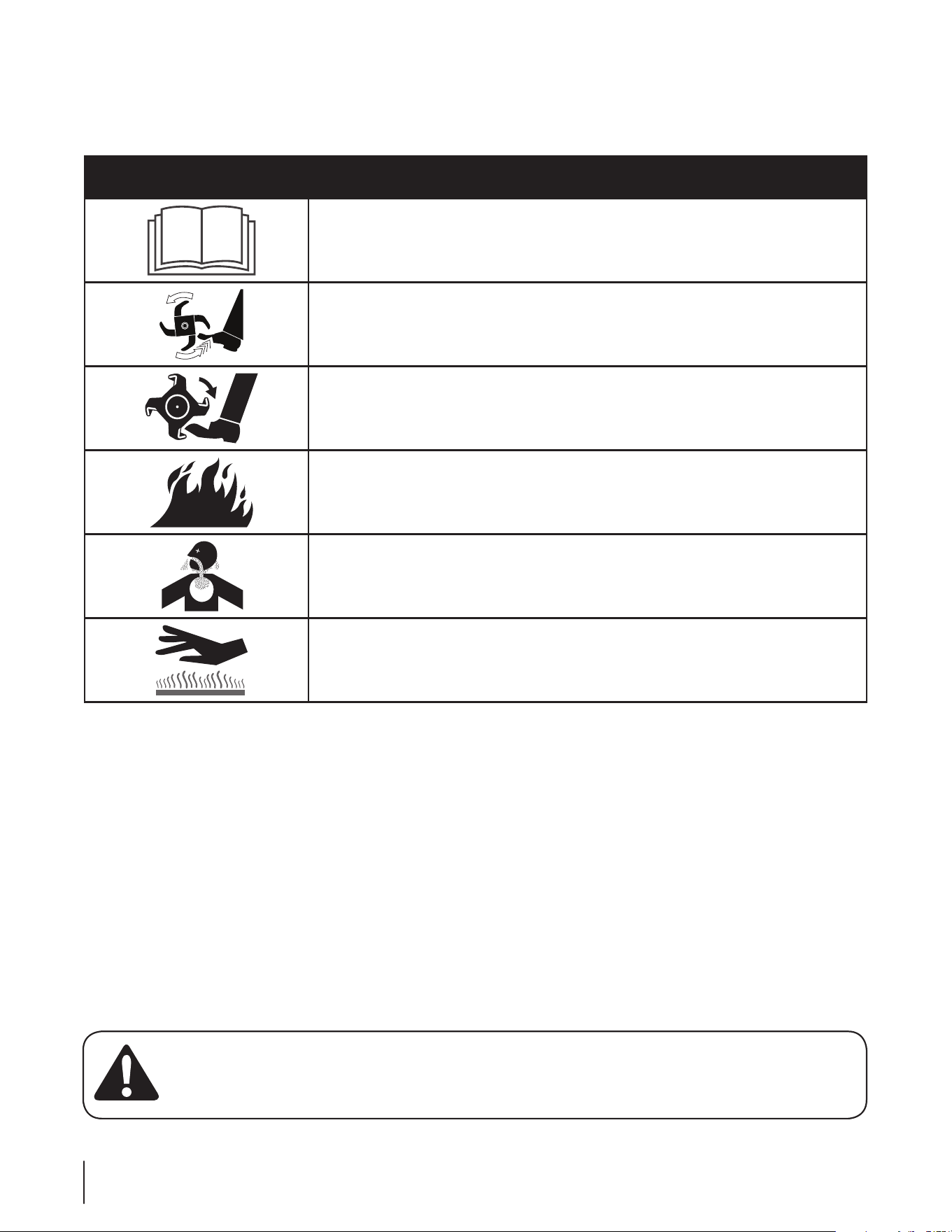
Safety Symbols
This page depicts and describes safety symbols that may appear on this product. Read, understand, and follow all instructions on the
machine before attempting to assemble and operate.
Symbol Description
READ THE OPERATOR’S MANUAL(S)
Read, understand, and follow all instructions in the manual(s) before attempting to
assemble and operate
WARNING— ROTATING TINES
Do not put hands or feet near rotating parts. Contact with the rotating parts can amputate
hands and feet.
WARNING— ROTATING TINES
Do not put hands or feet near rotating parts. Contact with the rotating parts can amputate
hands and feet.
WARNING—GASOLINE IS FLAMMABLE
Allow the engine to cool at least two minutes before refueling.
WARNING— CARBON MONOXIDE
Never run an engine indoors or in a poorly ventilated area. Engine exhaust contains carbon
monoxide, an odorless and deadly gas.
WARNING— HOT SURFACE
Engine parts, especially the muffler, become extremely hot during operation. Allow engine
and muffler to cool before touching.
WARNING! Your Responsibility—Restrict the use of this power machine to persons who read, understand and
follow the warnings and instructions in this manual and on the machine.
SAVE THESE INSTRUCTIONS!
Assembly & Set-Up
3
7
Contents of Carton
• One Tiller • One Handlebar Assembly • One Bottle of Engine Oil
• Two Cable Ties • One Operator’s Manual • One Engine Operator’s Manual
NOTE: Reference to the right or left side of the tiller is
determined from the operator’s position behind the machine. All
exceptions will be noted.
WARNING! To prevent personal injury or property
damage, do not start the engine until all assembly
steps are complete and you have read and
understand the Safe Operation Practices Section
and the Operating Section in this manual.
Assembly
Unpacking Instructions
1. Remove the staples, break the glue on the top flaps, or cut
the tape at the end of the carton and peel along the top
flap to open carton.
2. Remove the loose parts included with the tiller (i.e.,
Operator’s Manual, etc.).
3. Cut the corners and lay the carton down flat.
4. Remove the packing materials.
5. Roll or slide the tiller out of the carton. Check the carton
thoroughly for loose parts.
6. Extend the control cable and lay it on the floor. Be careful
not to bend or kink the control cable.
NOTE: This tiller is shipped without gasoline or oil in the
engine. Be certain to service engine with gasoline and oil as
instructed in the separate Engine Operator’s Manual before
operating your machine.
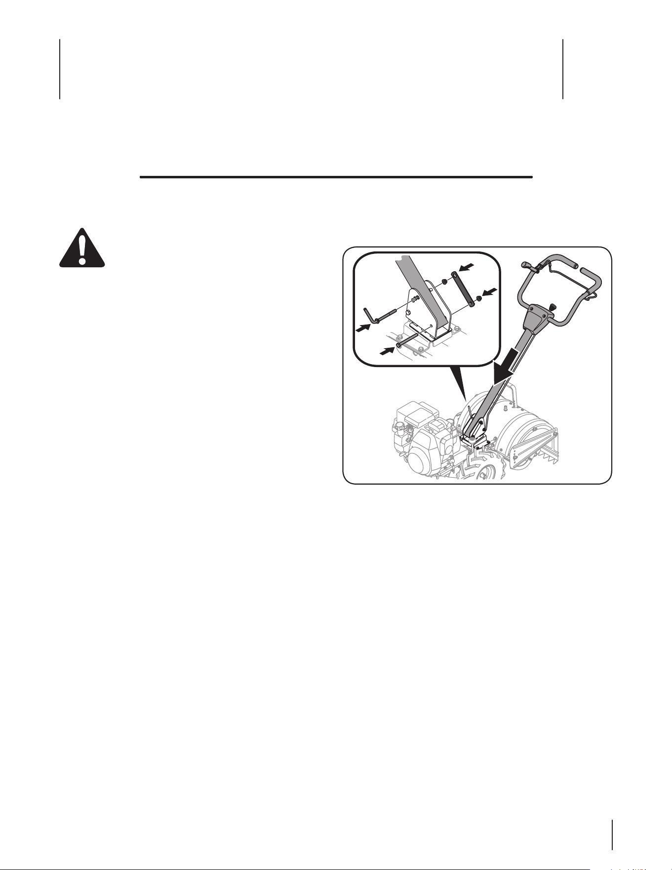
Handle
1. Remove the hex screw, handle crank adjuster, retainer
bracket and flange lock nuts from the handle mounting
brackets. See Figure 3-1.
Figure 3-1
2. Place the handle assembly in position between the handle
bracket. See Figure 3-1.
3. Line up the holes in the handle with the holes in the
bracket and secure it with hardware previously removed.
8 Section 3— ASSembly & Set-Up
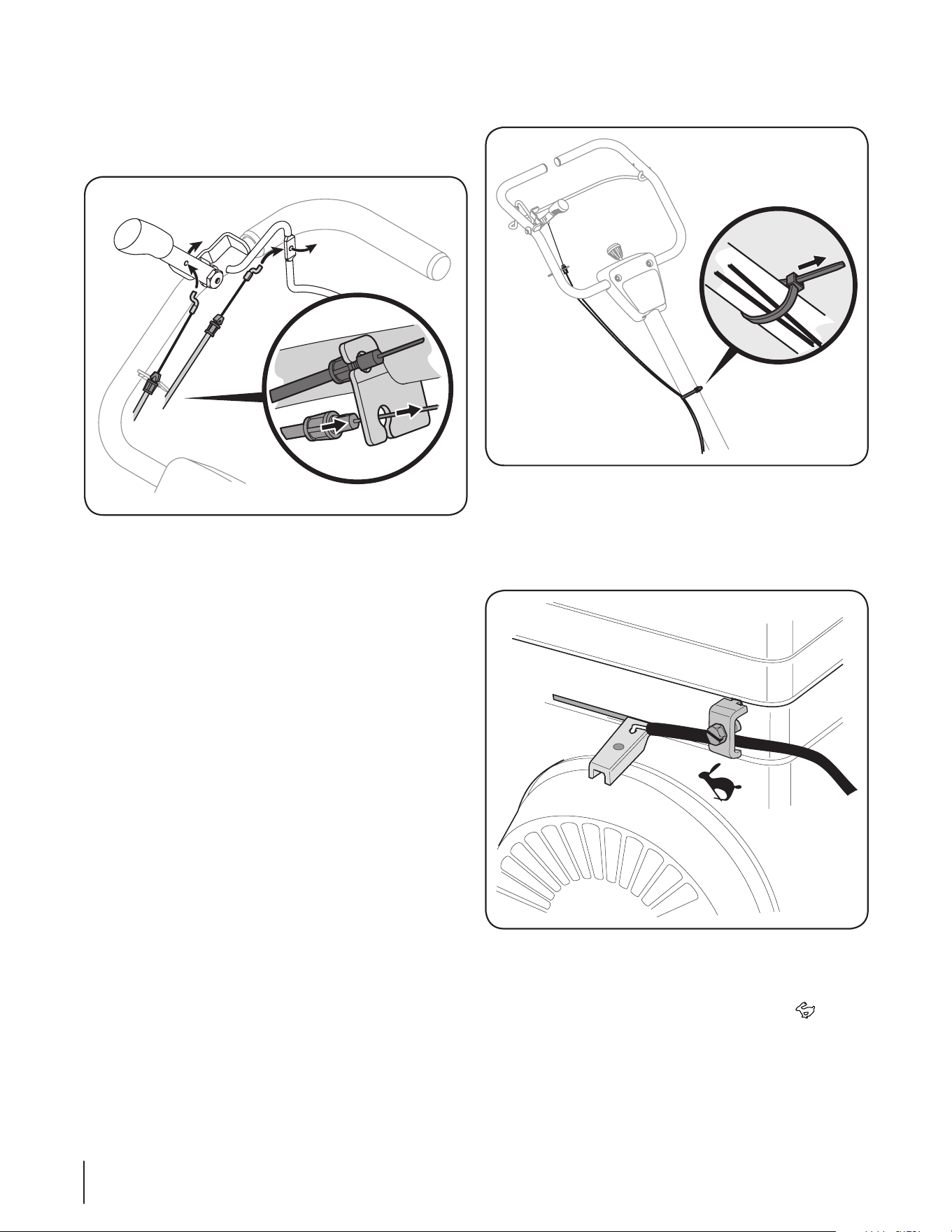
Forward & Reverse Clutch Cables
To attach the cables, follow these steps:
1. Route the forward (black) clutch cable along the handle
assembly on the right-hand side. See Figure 3-2.
Red
Red
Black
Black
Figure 3-2
2. Connect the forward clutch cable to the forward clutch
bail by feeding the z-hook through the hole on the bail
from the outside towards the inside. See Figure 3-2.
3. Snap the cable housing clips into the handle assembly
cable mount as shown in Figure 3-2. The clip feeds into the
lower position on the handle assembly. See Figure 3-2.
NOTE: To test the function of the forward clutch bail, lift
the bail to the handle and release it. The bail should return
to its neutral position. If it doesn’t, contact your local dealer
for technical assistance.
4. Route the reverse (red) clutch cable along the handle
assembly on the right-hand side. See Figure 3-2.
5. Connect the reverse clutch cable to the reverse clutch
handle by feeding the z-hook through the hole on the
handle from the inside towards the outside. See Figure 3-2.
6. Snap the cable housing clips into the handle assembly
cable mount as shown in Figure 3-2. The clip feeds into the
upper position on the handle assembly.
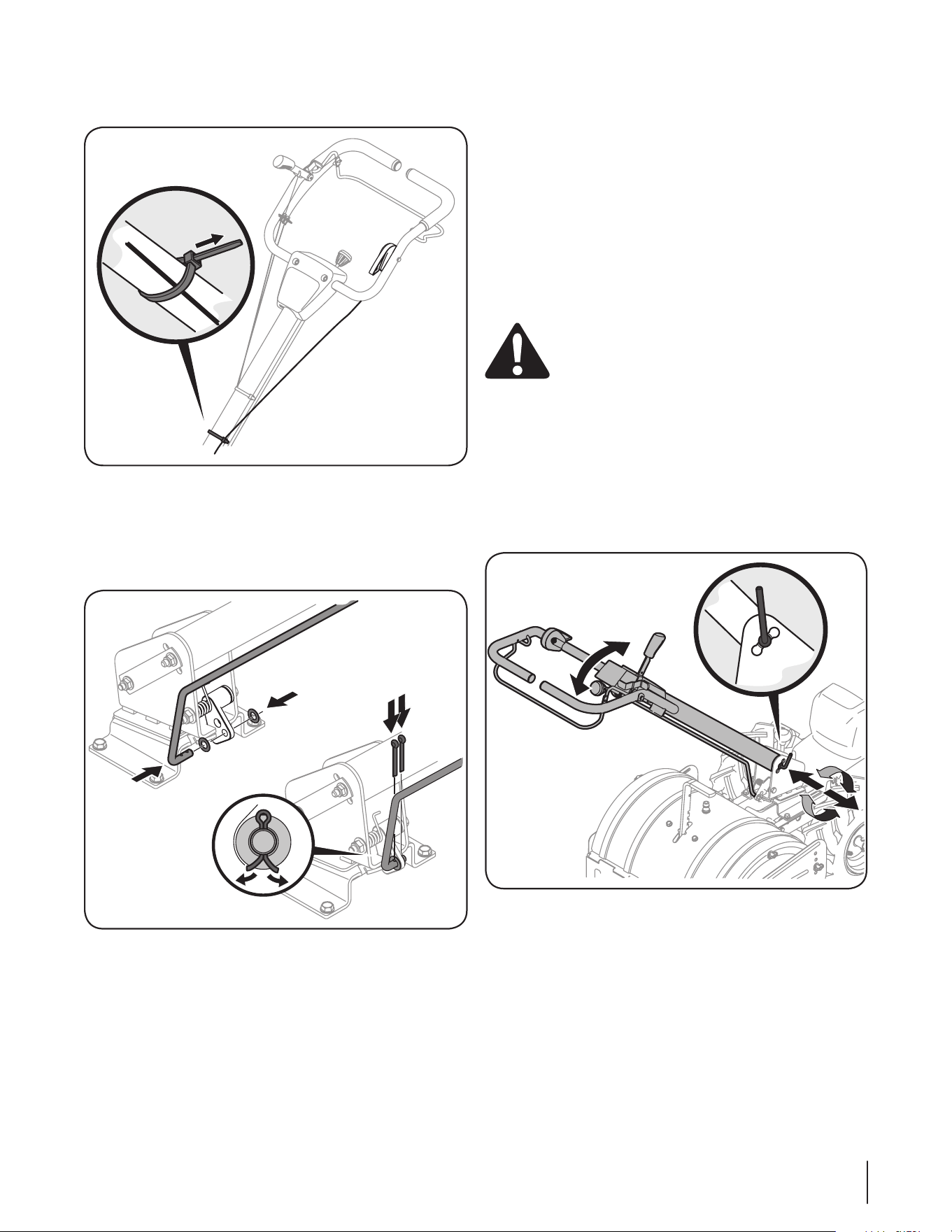
7. Using a cable tie secure the two cables onto the handle
about mid-way down the shaft. See Fig. 1-3.
Figure 3-3
Throttle Cable
1. Remove the casing clamp and screw from the front left of
the engine and hook the throttle cable into the throttle as
shown in Figure 3-4.
Figure 3-4
2. Reinstall the casing clamp and screw but do not fully
tighten the screw yet.
3. Slide the throttle lever all the way into the RUN position
then fully tighten the screw to secure the throttle cable in
place.
9Section 3 — ASSembly & Set-Up
4. Secure the throttle cable to the handle with a cable tie as
shown in Figure 3-5.
Figure 3-5
Handle Pivot Control Rod
1. Secure the handle pivot rod control onto the swing handle
link using the two thrust washers and cotter pins as shown
in Figure 3-6.
Figure 3-6
2. Once in place, secure the handle by bending the cotter pins
outward.
Set-Up
Tires
The tires on the tiller may be over-inflated for shipping purposes.
Reduce the tire pressure before operating the tiller. Recommended
operating tire pressure is approximately 20 PSI (check the sidewall
of the tire for the manufacturer’s recommended pressure). Be sure
that both tires are inflated equally or the tiller will pull to one side.
Gas & Oil Fill-Up
Service the engine with gasoline and oil as instructed in the
separate Engine Operator’s Manual packed with your tiller. Read
the instructions carefully.
WARNING! Use extreme care when handling
gasoline. Gasoline is extremely flammable and the
vapors are explosive. Never fuel the machine
indoors or while the engine is hot or running.
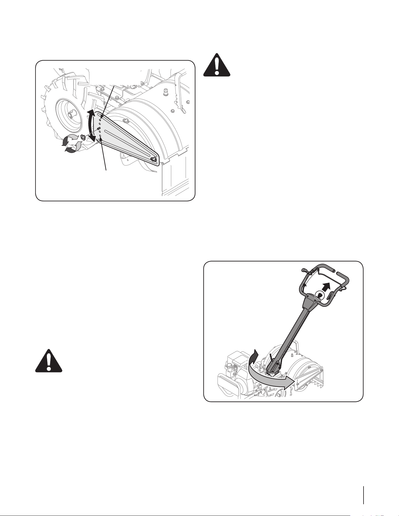
Adjustments
Handle
The handle should be adjusted so that when the tiller is digging
3-4” into the soil, the handle falls to about waste-high. Rotate
the handle adjustment lock rearward, move the handle to the
desired position and then lock into place by rotating the handle
adjustment lock forward to secure the handle. See Figure 3-7.
Figure 3-7
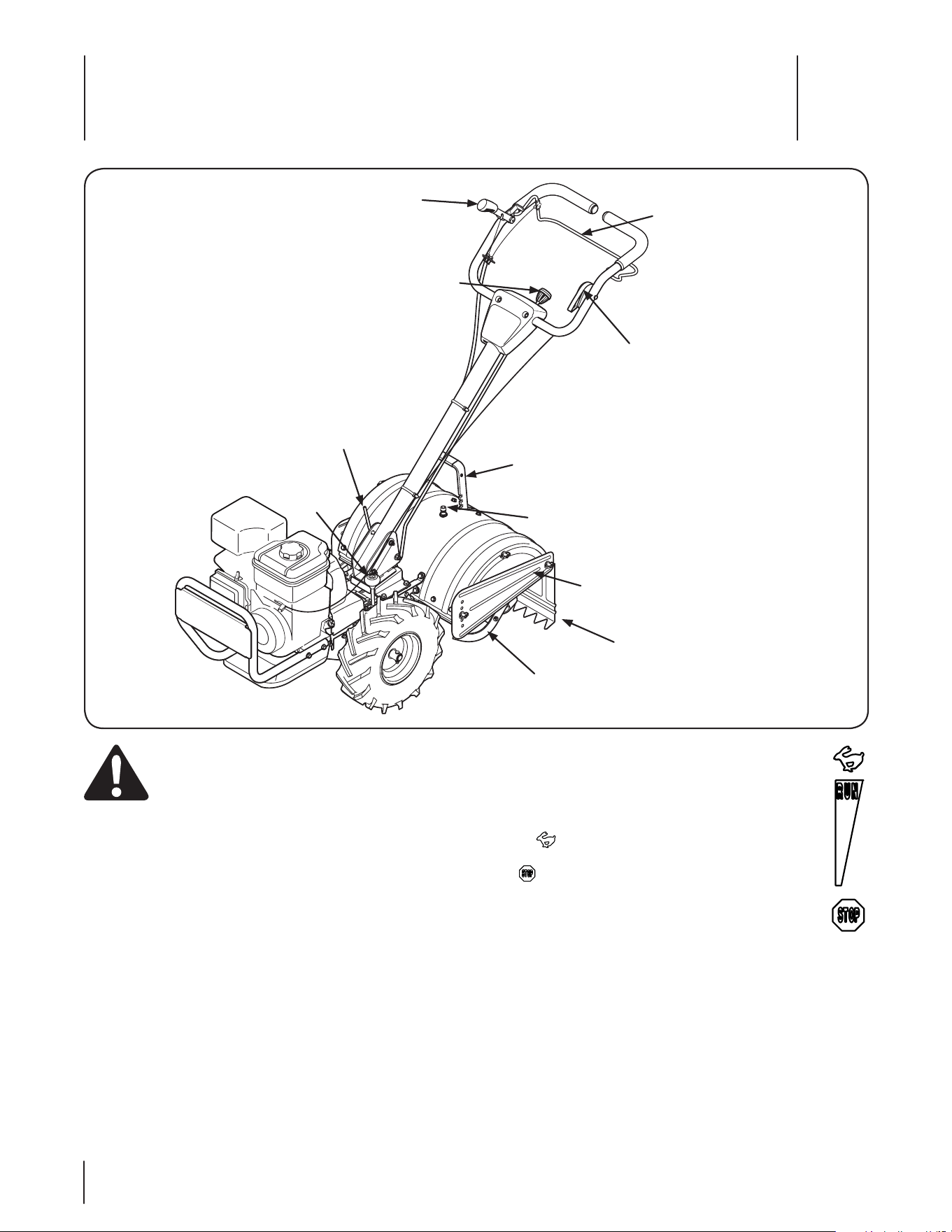
Controls & Features
4
10
Forward Clutch Bail
Reverse Clutch Handle
Throttle Control
Handle Pivot Control Knob
Handle Adjustment Lock
Neutral
Lever
Depth Adjustment Lever
Side Shield
Tines
Rear Tine Shield
Tine Shield Wash Nozzle
WARNING! Before operating your machine,
carefully read and understand all safety, controls
and operating instructions in this manual and on the
decals on the machine. Failure to follow these
instructions can result in serious personal injury.
Forward Clutch Bail
The forward clutch bail is located on the upper handle and
controls the engagement of the forward drive of the wheels
and engages the tines. See the Operation section for more
information on using the forward clutch bail.
Reverse Clutch Handle
The reverse clutch handle is located on the right side of the
upper handle and controls the engagement of the rearward drive
of the wheels and engages the tines. See the Operation section
for more information on using the reverse clutch handle.
Throttle Control
The throttle control is located on the inside, left of the
upper handle and controls the engine speed. Push the
throttle control forward to increase the engine speed.
The tiller is designed to be operated with the throttle in
the RUN (full throttle) position. Pull the throttle back
to decrease the engine speed and all the way back to the
STOP position to stop the engine.
Depth Adjustment Lever
This lever controls the tilling depth of the tines. Pull the
lever back and slide it up or down to engage the notched height
settings. See the Operation section for more information on using
the depth adjustment lever.
Handle Adjustment Lever
The handle adjustment lever is used to adjust the handle height
and is adjustable to three different settings. In general, adjust
the handlebars so they are at waist level when the tines are
3-4” in the ground. See the Assembly & Set-Up section for more
information on the handle adjustment Lever.

11Section 4 — controlS & FeatureS
Rear Tine Shield
The rear tine shield protects the operator from flying debris
while also smoothing out freshly tilled soil.
Side Shield
The side shields are located on the right and left sides of the
tine shield and can be used with the depth adjustment lever
to control tilling depth. See the Operation section for more
information on using the side shields.
Tines
Your tiller’s tines are a series of hoes arranged on a revolving
power-driven shaft.
Neutral Lever
The neutral lever allows the wheels to be positioned in either a
drive or a neutral/freewheel mode. See the Operation section for
more information on using the neutral lever.
Handle Pivot Control Knob
The handle pivot control knob is located on the upper handle
and in the center of the handle. The knob is used to pivot the
handle to one of three positions. See the Operation section for
more information on using the handle pivot control knob.
Tine Shield Wash Nozzle
The tine shield wash nozzle is located on top of the tine shield.
The nozzle can be attached to a hose and used to clean dirt and
debri out of the tines and the inside of the tine shield. See the
Maintenance & Adjustments section for more information on the
tine shield wash nozzle.
Operation
5
12
Starting the Engine
WARNING! Read, understand, and follow all
instructions and warnings on the machine and in
this manual before operating.
NOTE: When pushing the tiller with the engine off, you will hear a
ratcheting sound or gear noise; this is normal.
WARNING! Be sure no one is standing in front of
the tiller while the engine is running or being
started.
1. Place the neutral lever in the NEUTRAL position by pulling
back on the neutral lever and moving it to the right. See
Figure 5-1.
NeutralDrive
Figure 5-1
2. Move the throttle control into the run position and
follow the instructions in the Engine Operator’s manual to
start the engine.
Stopping the Engine
To stop the engine place the throttle in the STOP position and
refer to the Engine Operator’s Manual.
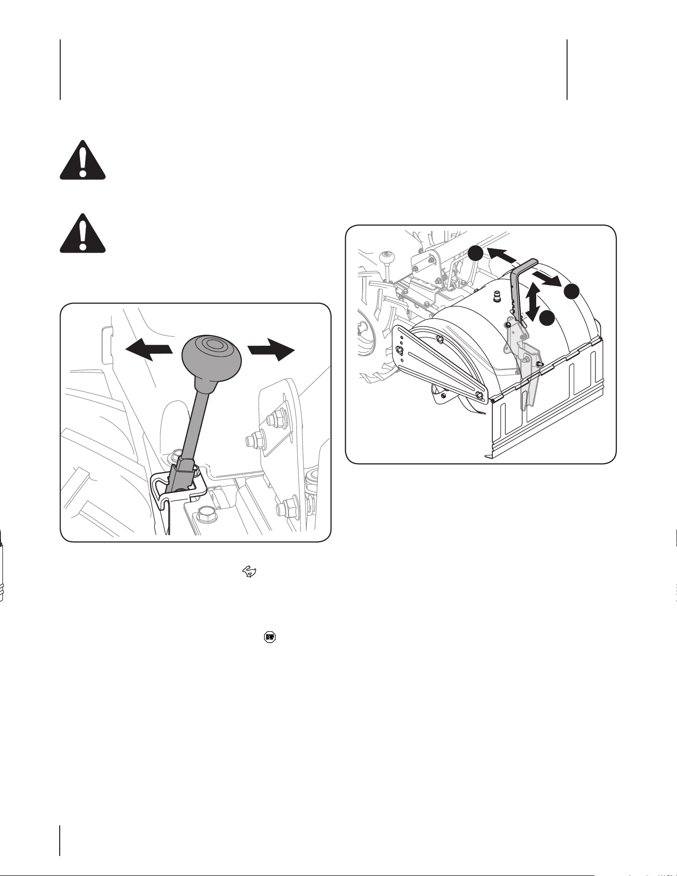
Setting The Depth
Tilling depth is controlled by the depth stake which can be
adjusted to seven different settings. Adjust the side shields as
you adjust the depth stake.
1. Pull back on the depth adjustment lever (a), move the lever
up or down into the desired tilling depth (b) and move back
forward to lock into place (c). See Figure 5-2.
A
B
C
Figure 5-2
2. When using the tiller for the first time, use the second
adjustment slot from the top. See Figure 5-2.
13Section 5 — operation
3. To adjust the side shields, remove the wing nuts. Move the
side shield to the desired position and replace the wing
nuts. Tighten securely. See Figure 5-1.
Use This Hole for
Lowest/Shallowest
Position
Use this Hole for
Highest/Deepest
Position
Figure 5-3
4. When breaking up sod and for shallow cultivation, use the
second slot from the top. Place the side shields in their
lowest position. See Figure 5-3.
5. For further depth, raise the depth adjustment lever and side
shields and also make one or two more passes over the area.
6. When tilling loose soil, the depth adjustment lever may be
raised to its highest position (use the bottom adjustment
slot) to give the deepest tilling depth. Raise the side shields
to their highest position.
7. To transport the tiller, lower the depth stake and use the
top adjustment slot.
Operating the Tiller
1. Select the depth adjustment lever setting.
2. Start the engine as instructed on the previous page.
3. Move the neutral lever into the drive position.
WARNING! Do not move the neutral lever into
drive with the tines engaged. Make certain the tiller
is stopped completely before placing tiller in drive. A
partial engagement may be necessary when
engaging tines.
4. To shift into forward wheels and tine drive, slowly engage
the forward clutch bail allowing the gears to synchronize.
To stop forward movement and tine drive, release the
forward clutch bail. Do not shift from neutral to drive or
drive to neutral with the forward clutch bail engaged.
5. Squeeze the clutch handle against the handle to engage
the wheels and tines.
WARNING! Do not push down on the handles so
that the wheels are lifted off the ground while using
the tine drive, or the tiller could move backward and
cause personal injury.
6. For best results, it is recommended the garden be tilled
twice (lengthwise, then width-wise) to pulverize the soil.
To move in reverse: (Do not till in reverse)
1. Release the forward clutch bail. Then lift the handlebar
until the tines are off the ground.
2. Pull back on the reverse clutch handle and walk backwards
with the machine.
Turning the tiller
MANUALLY
1. Practice turning the tiller in a level, open area. Be very
careful to keep your feet and legs away from the tines.
2. To begin a turn, lift the handlebars until the tines are out of
the ground and the engine and tines are balanced over the
wheels.
3. With the tiller balanced, push sideways on the handlebar to
steer in the direction of the turn. After turning, slowly lower
the tines into the soil to resume tilling.
USING THE SWING LEVER
1. The tiller handle can be swivelled in either direction.
The pivot control handle enables the tiller to be guided
sideways to the next row. See Figure 5-4.
Figure 5-4
2. Pull up on the handle pivot control knob to release the handle.
3. Swivel the handle into the desired position.
4. Release the handle pivot control knob to secure the handle
in place.
Maintenance & Adjustments
6
14
WARNING! Disconnect the spark plug wire and
ground it against the engine before performing any
maintenance or repairs.
Maintenance
Engine
Refer to the separate Engine Operator’s Manual for engine
maintenance instructions.
Tires
Recommended operating tire pressure is approximately 20 p.s.i.
on 16” tires. (Check the sidewall of the tire for the manufacturer’s
recommended pressure). Maximum tire pressure under any
circumstances is 30 p.s.i. Equal tire pressure should be maintained
on both tires.
WARNING! Excessive pressure (over 30 p.s.i.) when
seating beads may cause the tire/rim assembly to
burst with force sufficient to cause serious injury.
Tines
Use the Smart Jet™ to rinse dirt from the tines and the tine shield
and prevent the buildup of corrosive chemicals. Complete the
following steps right after tilling to prevent dirt from hardening
and becoming more difficult to remove:
1. Move the tiller to a level, clear spot on your lawn, near
enough for your garden hose to reach.
1. Disengage the tines and stop the engine.
2. Thread the hose coupler onto the end of your garden hose.
3. Attach the hose coupler to the water port on the top of
your tine shield. See Figure 6-1.
Figure 6-1
4. Place the depth adjustment lever in the the highest position.
5. Place the neutral lever in the neutral position.
6. Turn the water on.
7. While standing in the operator’s position behind the tiller,
start the engine and place the throttle in the FAST
position.
8. Engage the tines.
9. Remain in the operator’s position with the tines engaged
for a minimum of two minutes, allowing the underside of
the tine shield to thoroughly rinse.
10. Disengage the tines.
11. Place the throttle in the STOP position to turn the
tractor’s engine off.
12. Turn the water off and detach the hose coupler from the
water port on your tine shield.
13. After cleaning your tines and tine shield with the Smart Jet™
system, return to the operator’s position and engage the
tines. Keep the tines engaged for a minimum of two minutes,
allowing the tines to thoroughly dry.
Transmission Gear Oil
Check the transmission gear oil after every 30 hours of operation
or whenever you notice any oil leak. Operating the tiller when
the transmission is low on oil can result in severe damage.
To Check the Transmission Gear Oil Level:
1. Check the gear oil level when the transmission is cool. Gear
oil will expand in warm operating temperatures and this
expansion will provide an incorrect oil level reading.
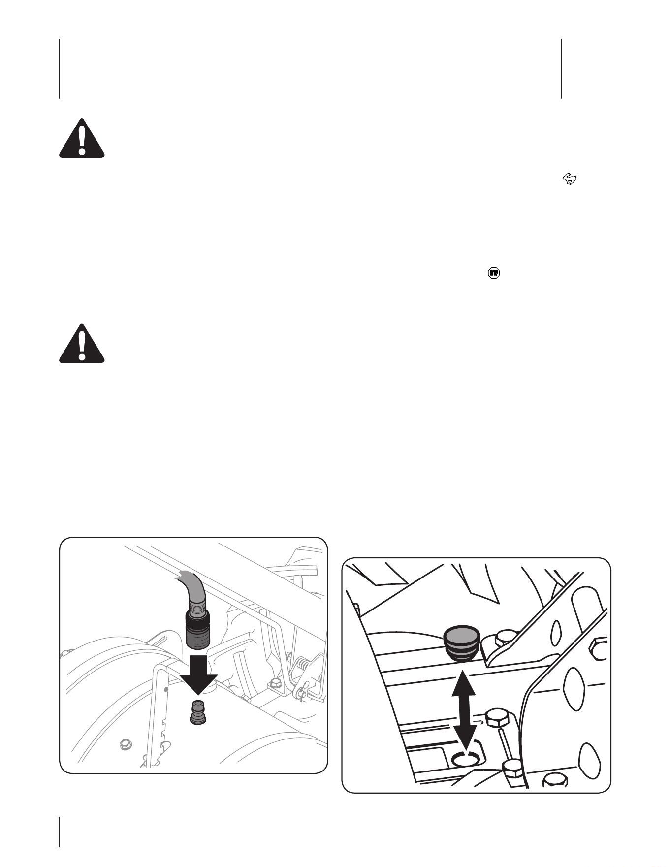
2. With the tiller on level ground, pull the depth adjustment
lever all the way up.
3. Remove the oil fill plug from the transmission housing and
look inside the oil fill hole to locate the main drive shaft
situated below the hole. See Figure 6-2.
Figure 6-2

15Section 6 — Maintenance & adjuStMentS
4. The gear oil level is correct if the gear oil is approximately
halfway up the side of the main drive shaft.
5. If the gear oil level is low, add gear oil as described next. If
the gear oil level is okay, securely replace the oil fill plug.
6. If adding only a few ounces of gear oil, use API rated GL-4
or GL-5 gear oil having a viscosity of SAE 140, SAE 85W-140
or SAE 80W-90. If refilling an empty transmission, use only
GL-4 gear oil having a viscosity of SAE 85W-140 or SAE 140.
7. While checking frequently to avoid overfilling, slowly add
gear oil into the oil fill hole until it reaches the halfway
point on the drive shaft.
8. Securely replace the oil fill plug.
Lubrication
Clutch Handle
Lubricate the pivot point on the clutch handle and the cable at
least once a season with light oil. The control must operate freely
in both directions.
Pivot Points
Lubricate all the pivot points and linkages at least once a season
with light oil.
Tine Shafts
Remove the tine assemblies and lubricate the tine shafts at least
once a season.
Wheel Shafts
Remove the wheel assemblies and lubricate the axle shafts at
least once a season.
Adjustments
WARNING! Never attempt to make any
adjustments while the engine is running, except
where specified in the Operator’s Manual.
Engine Adjustment
Refer to the separate Engine Operator’s Manual for engine
adjustment instructions.
Handle
The handle may be adjusted to the desired height. Refer to the
Assembly & Set-Up section for details.
Off-Season Storage
If the tiller will not be used for a period longer than 30 days, the
following steps should be taken to prepare the tiller for storage.
• Clean the exterior of the engine and the entire tiller
thoroughly. Lubricate the tiller as described in the
Lubrication instructions.
• Using a pressure washer to clean your tiller is not
recommended. The washer may cause damage to the
electric components, spindles, pulleys, bearings or the
engine. Using a pressure washers will result in shortened
life and reduce serviceability.
• Engines stored between 30 and 90 days need to be treated
with a gasoline stabilizer such as STA-BIL® and engines
stored over 90 days need to be drained of fuel to prevent
deterioration and gum from forming in fuel system or on
essential carburetor parts. If the gasoline in your engine
deteriorates during storage, you may need to have the
carburetor, and other fuel system components, serviced or
replaced.
• Refer to the Engine Operator’s Manual for the additional
engine storage instructions.
• Wipe the tines with an oiled rag to prevent rust.
• Store the tiller in a clean, dry area. Do not store next to
corrosive materials, such as fertilizer.
NOTE: When storing any type of power equipment in
an unventilated area or metal storage shed, care should
be taken to rustproof the equipment. Using a light oil or
silicone, coat the equipment and especially any springs,
bearings, and cables.
Se rvi ce
7
16
Belt Replacement
If the drive belt need to be replaced, it is best to replace both
belts at the same time. Use only a factory-authorized belt as
an “over- the-counter” belt may not perform satisfactorily. The
procedure requires average mechanical ability and commonly
available tools.
To replace the Drive and Reverse belts, follow these steps:
1. Make sure the tiller is on a flat surface, with the engine
turned off and the spark plug wire unplugged and
grounded to prevent unintended firing of the engine.
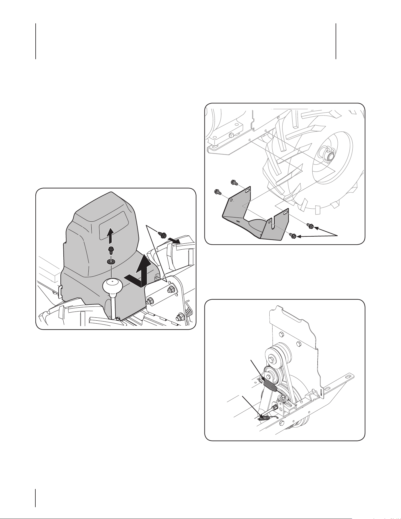
2. Remove the belt cover as seen in Figure 7-1, by first
removing the two hex washer screws and one flat washer.
Lift the belt cover up and away from the tiller and set in a
safe location until reinstallation.
Figure 7-1
3. Remove the four hex washer screws that secure the pulley
shield to the frame as seen in Figure 7-2, and remove
the pulley shield and set aside in a safe location until
reinstallation.
Hex Washer
Screws
Figure 7-2
4. Remove the idler bracket extension spring from the idler
bracket using a pair of needle-nosed pliers. Grab the spring
by the end that hooks over the frame, pull it away from the
frame, then up and carefully relieve the tension of the spring.
See Figure 7-3.
Remove the
idler bracket
extension
spring
Drive Cable
Figure 7-3
17Section 7 — Service
5. Unhook the drive cable from the idler bracket. See Figure 7-3.
6. Remove the belt from the transmission, engine and idler
pulleys.
7. Replace the old belt with a new belt. Make sure the belt is
installed into the pulleys closest to the tines/front of the tiller.
8. Re-install the drive cable on the idler pulley.
9. Carefully re-install the idler bracket extension spring on the
idler bracket.
10. Reassemble the tiller in the reverse order in which it was
disassembled.
NOTE: When reinstalling the belt cover, be sure to engage the
bail and hold it so that the drive belt is tight before attempting
to reinstall the belt cover. This will enable the belt to fall under
the belt keeping mechanism built into the belt cover. Failure
to do so could damage the belt and/or belt cover.
NOTE: The longer screw goes into the top, forward facing hole
in the belt cover.
Tines
The tines will wear with use and should be inspected at the
beginning of each tilling season and after every 30 operating
hours. Tines can be replaced individually or as a complete set.
Never inspect or service the tines unless the engine is stopped
and the spark plug wire is disconnected.
With use, the tines will become shorter, narrower and pointed.
Badly worn tines will result in a loss of tilling depth and reduced
effectiveness when chopping up and turning under organic matter.
Removing a Tine Assembly
1. If removing both tine assemblies, mark them “left” and
“right” before removal. Doing so will help ensure that the
assemblies are reinstalled on the correct sides of the tiller.
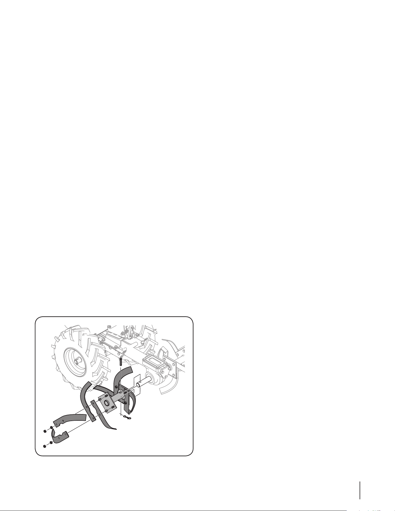
2. Remove theclevis pin and cotter pin that secure the tine
assembly to the tine shaft. See Figure 7-4. Pull the tine
assembly off the shaft. If necessary, use a rubber mallet to
tap the tine assembly outward.
Figure 7-4
3. Before reinstalling the tine assembly, inspect the tine shaft
for rust, rough spots or burrs and file or sand as needed.
Then apply a thin coat of grease to the shaft.
4. Install each tine assembly so that the cutting edge of the
tines will enter the soil first when the tiller moves forward.
Secure the tine assembly to the tine shaft using the clevis
pin and cotter pin previously removed. Tighten securely.
Replacing a Single Tine
1. Remove the two screws and nuts that attach a single tine
to the tine holder. If needed, use penetrating oil to help
free the nuts. See Figure 7-4.
2. When installing a single tine, be sure to position it so that
its cutting edge will enter the soil first as the tiller moves
forward.
Change Transmission Gear Oil
NOTE: The transmission gear oil does not need to be changed
unless it has been contaminated with dirt, sand or metal particles.
See an authorized service dealer to have the transmission gear oil
changed. Refer to the phone numbers on page 2 of this manual
to locate the nearest service dealer.

Troubleshooting
8
18
Problem Cause Remedy
Tines do not engage 1. Foreign object lodged in tines.
2. Tine clevis pin(s) missing.
3. Pulley and idler not in correct adjustment.
4. Not shifting properly.
5. Belt worn and/or stretched.
1. Dislodge foreign object.
2. Replace tine clevis pin(s).
3. Take tiller to authorized service dealer.
4. Refer to the Operation Section for proper
shifting procedures.
5. Replace belt.
Wheels do not engage 1. Nut and bolt missing
2. Tiller is not being shifted properly.
3. Belt worn and/or stretched.
1. Replace nut and bolt.
2. Refer to Operation Section for proper shifting
procedures.
3. Replace belt.
Replacement Parts
9
19
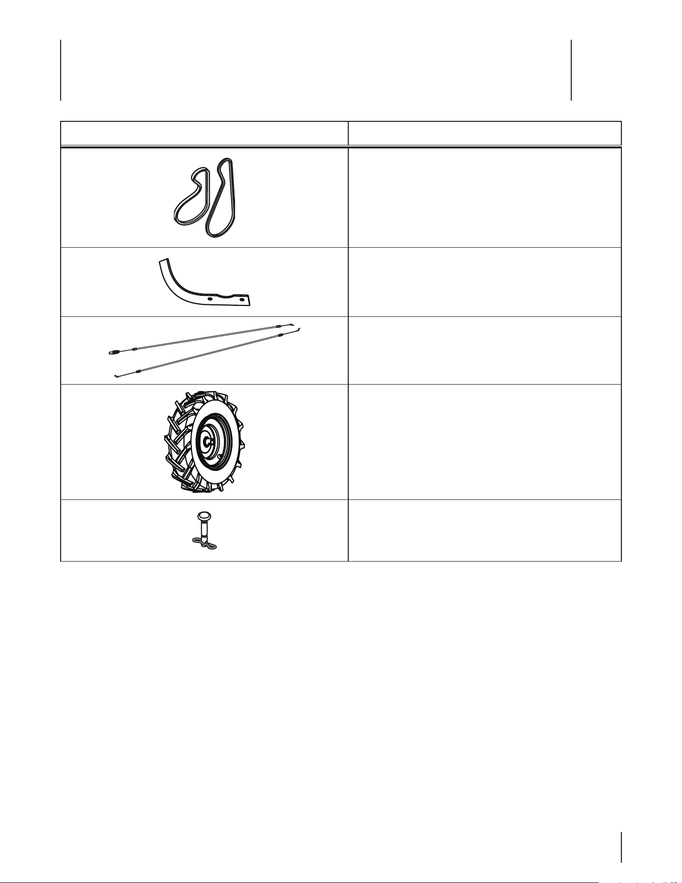
Component Part Number and Description
954-04090 Reverse V-Belt
954-04091 Forward V-Belt
742-05065 LH Tine
742-05064 RH Tine
946-04506 Forward Drive Cable
946-04504 Reverse Drive Cable
634-05054 Tires, 14 x 4.5-6
714-04043 Cotter Pin, Tine Assembly
911-0415 Clevis Pin, Tine Assembly
Phone (800) 965-4CUB to order replacement parts or a complete Parts Manual (have your full model number and serial number
ready). Parts Manual downloads are also available free of charge at www.cubcadet.com.

The limited warranty set forth below is given by Cub Cadet LLC
with respect to new merchandise purchased and used in the United
States, its possessions and territories, and by MTD Products Limited
with respect to new merchandise purchased and used in Canada
and/or its territories and possessions.
This warranty is in addition to any applicable emissions warranty
provided with your product.
“Cub Cadet” warrants this product (excluding its Normal Wear Parts
as described below) against defects in material and workmanship
for a period of three (3) years commencing on the date of original
purchase and will, at its option, repair or replace, free of charge,
any part found to be defective in materials or workmanship. This
limited warranty shall only apply if this product has been operated
and maintained in accordance with the Operator’s Manual
furnished with the product, and has not been subject to misuse,
abuse, commercial use, neglect, accident, improper maintenance,
alteration, vandalism, theft, fire, water, or damage because of other
peril or natural disaster. Damage resulting from the installation
or use of any part, accessory or attachment not approved by Cub
Cadet for use with the product(s) covered by this manual will void
your warranty as to any resulting damage.
Normal Wear Parts are warranted to be free from defects in material
and workmanship for a period of thirty (30) days from the date of
purchase. Normal wear parts include, but are not limited to items
such as: batteries, belts, blades, tines, wheels and tires.
HOW TO OBTAIN SERVICE: Warranty service is available, WITH
PROOF OF PURCHASE, through your local authorized service dealer.
To locate the dealer in your area:
In the U.S.A.
To locate the dealer in your area, check your Yellow Pages, or
contact Cub Cadet LLC at P.O. Box 361131, Cleveland, Ohio 44136-
0019, or call 1-877-282-8684, or log on to our Web site at www.
cubcadet.com.
In Canada
Contact MTD Products Limited, Kitchener, ON N2G 4J1, or call
1-800-668-1238 or log on to our Web site at www.mtdcanada.com.
This limited warranty does not provide coverage in the following
cases:
a. The engine or component parts thereof. These items may
carry a separate manufacturer’s warranty. Refer to applicable
manufacturer’s warranty for terms and conditions.
b. Routine maintenance items such as lubricants, filters, blade
sharpening, tune-ups, brake adjustments, clutch adjustments,
deck adjustments, and normal deterioration of the exterior
finish due to use or exposure.
c. Cub Cadet does not extend any warranty for products sold
or exported outside of the United States and/or Canada, and
their respective possessions and territories, except those
sold through Cub Cadet’s authorized channels of export
distribution.
d. Replacement parts that are not genuine Cub Cadet parts.
e. Service completed by someone other than an authorized
service dealer.
f. Transportation charges and service calls.
g. Cub Cadet does not warrant this product for commercial use.
No implied warranty, including any implied warranty of
merchantability of fitness for a particular purpose, applies
after the applicable period of express written warranty above
as to the parts as identified. No other express warranty,
whether written or oral, except as mentioned above, given by
any person or entity, including a dealer or retailer, with respect
to any product, shall bind Cub Cadet. During the period of the
warranty, the exclusive remedy is repair or replacement of the
product as set forth above.
The provisions as set forth in this warranty provide the sole
and exclusive remedy arising from the sale. Cub Cadet shall
not be liable for incidental or consequential loss or damage
including, without limitation, expenses incurred for substitute
or replacement lawn care services or for rental expenses to
temporarily replace a warranted product.
Some states do not allow the exclusion or limitation of incidental
or consequential damages, or limitations on how long an implied
warranty lasts, so the above exclusions or limitations may not apply
to you.
In no event shall recovery of any kind be greater than the amount
of the purchase price of the product sold. Alteration of safety
features of the product shall void this warranty. You assume
the risk and liability for loss, damage, or injury to you and your
property and/or to others and their property arising out of the
misuse or inability to use the product.
This limited warranty shall not extend to anyone other than the
original purchaser or to the person for whom it was purchased as a
gift.
HOW STATE LAW RELATES TO THIS WARRANTY: This limited
warranty gives you specific legal rights, and you may also have
other rights that vary in different jurisdictions.
IMPORTANT: Owner must present Original Proof of Purchase to
obtain warranty coverage.
Cub Cadet LLC, P.O. BOX 361131 CLEVELAND, OHIO 44136-0019; Phone: 1-877-282-8684
MTD Canada Limited - KITCHENER, ON N2G 4J1; Phone 1-800-668-1238
GDOC-100087 REV. A
CUB CADET LLC
MANUFACTURER’S LIMITED WARRANTY FOR
EDGERS, STRING TRIMMERS & TILLERS

