DEC24.0101
ZRC-00TV
WARNING
WARNING - TO REDUCE THE RISK OF FIRE, ELECTRIC SHOCK,
OR INJURY TO PERSONS, OBSERVE THE FOLLOWING:
1. Use this unit only in the manner intended by the
manufacturer. If you have questions, contact the
manufacturer at the address or telephone number in the
warranty.
2. Before servicing or cleaning unit, switch power o at service
panel and lock the service disconnecting means to prevent
power from being switched on accidentally. When the
service disconnecting means cannot be locked, securely
fasten a prominent warning device, such as a tag, to the
service panel.
3. Installation work and electrical wiring must be done by a
qualified person(s) in accordance with all applicable codes
and standards, including fire-rated construction codes and
standards.
4. Sucient air is needed for proper combustion and
exhausting of gases through the flue (chimney) of fuel
burning equipment to prevent backdrafting. Follow the
heating equipment manufacturer's guideline and safety
standards such as those published by the National Fire
Protection Association (NFPA), and the American Society
for Heating, Refrigeration and Air Conditioning Engineers
(ASHRAE), and the local code authorities.
5. When cutting or drilling into wall or ceiling, do not damage
electrical wiring and other hidden utilities.
6. Ducted fans must always be vented to the outdoors.
7. To reduce the risk of fire, use only metal ductwork.
8. Do not install this product with the activating switch directly
behind a burner or element. Minimum distance between the
switch and the edge of the burner should be 4 inches.
9. Loose-fitting or hanging clothing should never be worn
when operating this appliance. They may be ignited by
burners/elements on cooktop.
10. Children should not be left alone or unattended in the area
where this appliance is in use.
11. This unit must be grounded.
WARNING - TO REDUCE THE RISK OF A RANGE TOP GREASE
FIRE:
a) Never leave surface units unattended at high settings.
Boilovers cause smoking and greasy spillovers that may ignite.
Heat oils slowly on low or medium settings.
b) Always turn hood ON when cooking at high heat or
when flambeing food. (i.e. Crepes Suzette, Cherries Jubilee,
Peppercorn Beef Flambe’).
c) Clean ventilating fans frequently. Grease should not be
allowed to accumulate on fan or filter.
d) Use proper pan size. Always use cookware appropriate for
the size of the surface element.
ZEPHYRONLINE.COM
WARNING
WARNING - TO REDUCE THE RISK OF INJURY TO PERSONS
IN THE EVENT OF A RANGE TOP GREASE FIRE, OBSERVE THE
FOLLOWINGa:
a) SMOTHER FLAMES with a close-fitting lid, cookie sheet, or
metal tray, then turn o the burner. BE CAREFUL TO PREVENT
BURNS. If the flames do not go out immediately, EVACUATE AND
CALL THE FIRE DEPARTMENT.
b) NEVER PICK UP A FLAMING PAN – You may be burned.
c) DO NOT USE WATER, including wet dishcloths or towels – a
violent steam explosion will result.
d) Use an extinguisher ONLY if:
1) You know you have a Class ABC extinguisher, and you
already know how to operate it.
2) The fire is small and contained in the area where it
started.
3) The fire department is being called.
4) You can fight the fire with your back to an exit
aBased on “Kitchen Firesafety Tips” published by NFPA.
CAUTION
1. For indoor use only.
2. For general ventilating use only. Do not use to exhaust
hazardous or explosive materials and vapors.
3. To avoid motor bearing damage and noisy and/or
unbalanced impellers, keep drywall spray, construction
dust, etc. o power unit.
4. Clean filters and grease-laden surfaces frequently.
5. Do not repair or replace any part of this appliance unless
specifically recommended in this manual. All other servicing
should be done by a qualified technician.
6. Please read specification label on product for further
information and requirements.
INSTALLER:
Save this manual for Electrical Inspector and
Homeowner to use.
Recirculating Kit for ZTV-E30AS and ZTV-E36AS
2
Installation Instructions
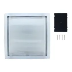
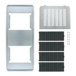
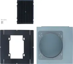
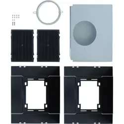
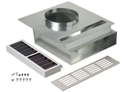
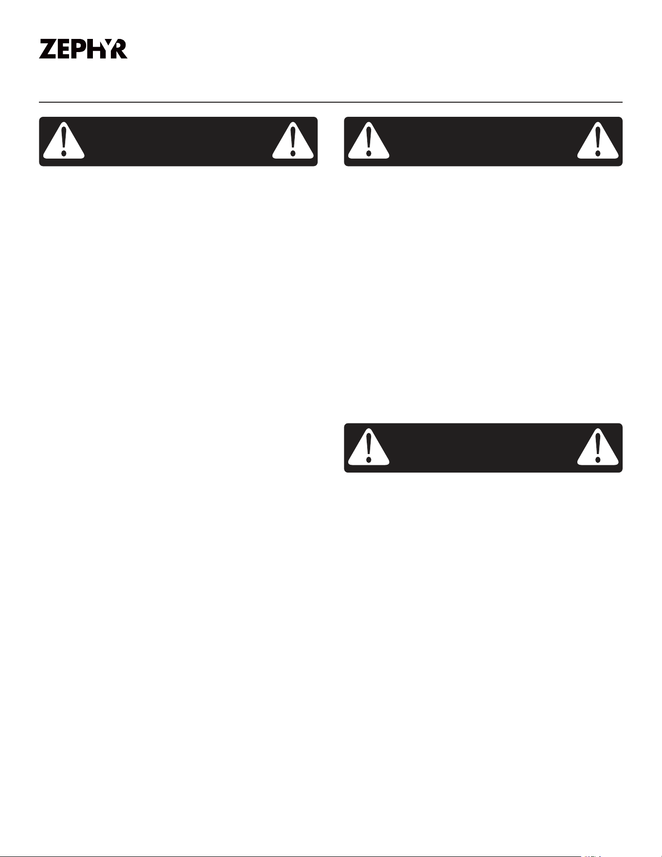
List of Materials
Charcoal Filter
Recirculation Box
Decorative Grille
Hardware Package
• (10) #6 x 1” screws
• (2) M4 x 8 screws
Dimensions
17-
7/16
”
16-
1/2
”
4-
3/8
”
1-
1/2
”
1-
1/8
”
3-
3/4
”
33.80
5-
7/8
”
15-
15/16
”
6-
1/2
”
1-
11/16
”
15-
15/16
”
13-
7/8
”
16”
15”
3-
3/4
”
1-
1/8
”
TOP VIEW
BACK VIEW
SIDE VIEW
3
ZEPHYRONLINE.COM
Installation Instructions
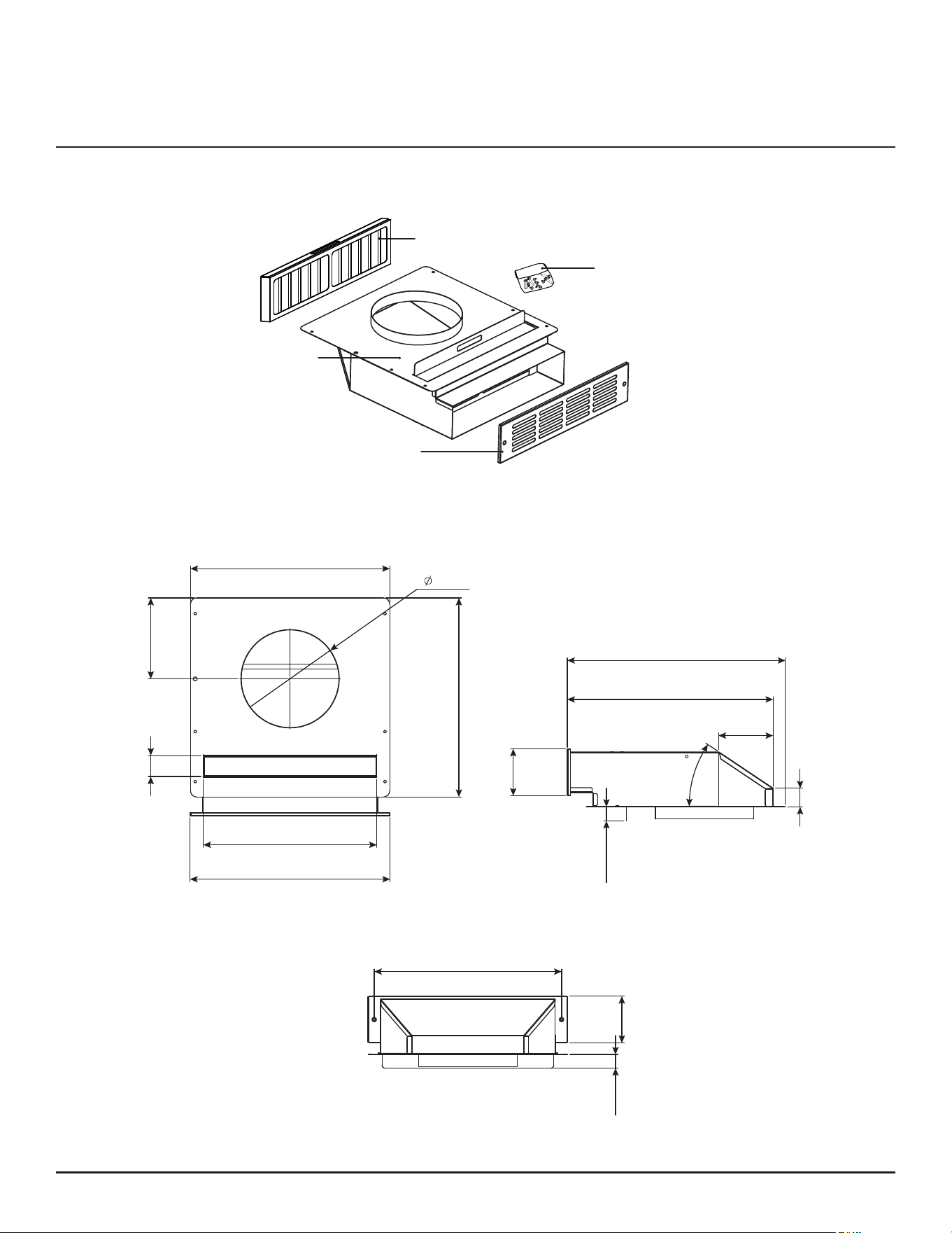
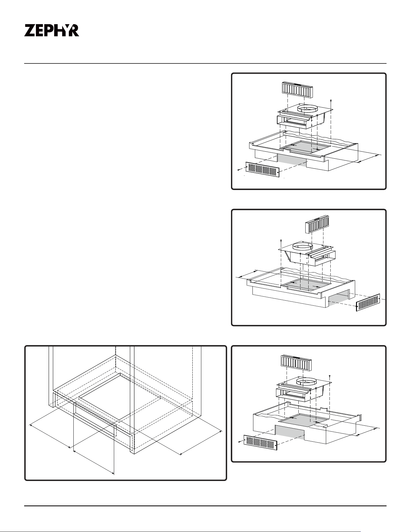
Plan the Installation
► A minimum 24-inch wide cabinet is recommended.
► The 6-inch round blower outlet and 6-inch round
recirculation box inlet must align vertically.
1. Determine where the recirculation box will exhaust
through the cabinet.
► Front side (toe space), left side, right side, or back
side.
► 14-3/16" x 14-9/16" opening in cabinet base is
required for recirculation box.
► 3-1/2" x 14-3/16" opening is required for the
exhaust.
2. Determine the location of the recirculation box.
► Plan to align the blower outlet with the
recirculation box inlet.
3. Determine what lengths of duct are required.
(Purchase duct separately)
► A length of flexible or rigid 6" duct is required to
connect blower exhaust to recirculation box inlet.
► A length of 3-1/2" x 14" duct may be required
to connect to exhaust of recirculation box and
extend to decorative grille location.
14-
3/16
”
3-
1/2
” x 14-
3/16
”
exhaust opening
14-
9/16
”
14-3/16”
14-9/16”
14-3/16”
14-9/16”
14-3/16”
14-9/16”
Exhaust through front of cabinet (toe space)
Exhaust through side of cabinet
Exhaust through back of cabinet
4
Installation Instructions
Install the Recirculation Box
1. Cut a 14-3/16" x 14-9/16" opening in the cabinet
base. The orientation depends on the direction of the
exhaust. Double check that the blower outlet and
recirculation box inlet aligns.
2. Temporarily place the recirculation box into the
opening of the cabinet base. Rotate back of the
recirculation box slightly and insert the exhaust end
down into the opening.
3. Mark location of the exhaust opening in the front (toe
space), sides, or rear of the cabinet.
4. Cut a 3-1/2" x 14-3/16" opening for the exhaust. This
opening will be covered by the decorative grille.
5. Install the recirculation box into the opening in the
cabinet base by (8) #6 x 1" screws. If necessary,
attach a length of 3-1/4" x 14" duct extension (not
included) to extend the recirculation box outlet to
decorative grille location. Seal the duct connection(s)
with duct tape to make them secure and air tight.
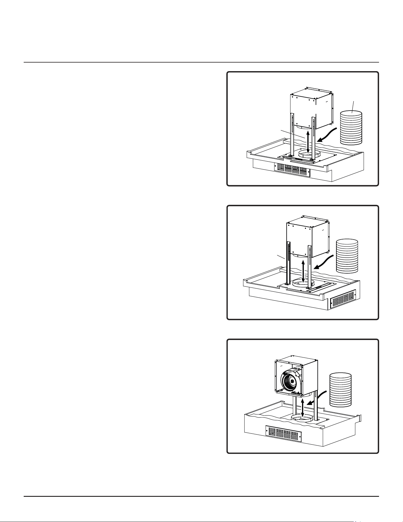
6. Install the blower by drilling 1/8" pilot holes through
the top of the recirculation box and attaching the
leveling brackets to the recirculation box with (2)
M4 x 8 screws. Use 6" round rigid duct to connect
the blower exhaust to the recirculation box inlet. Seal
the duct connections with duct tape to make them
secure and air tight.
7. Install the decorative grille by (2) #6 x 1" screws.
8. Remove polyfilm from filter by lifting the filter from
the slot, removing the polyfilm, and installing the
filter back into the slot.
Blower mounted to
downdraft using
mounting legs.
Metal 6” round
rigid duct (per
local codes)
Align blower outlet with
recirculation box inlet.
Blower
Exhaust through front of cabinet (toe space)
Exhaust through side of cabinet
Exhaust through back of cabinet
Mounting legs

5
ZEPHYRONLINE.COM
Installation Instructions
Filter Replacement
It is recommended that you replace the recirculation filter every 6 months. However, this may vary,
depending on the type and amount of cooking you perform. Call customer service or your local
distributor to order a filter replacement.
► Filter replacement part number: Z0F-C006
Custom-Made Decorative Grille
You can make your own decorative grille. Use the decorative grille in this kit as a template for the
overall size and mounting hole locations. The grille opening pattern is up to you.
► Equivalent area for grille slots for proper air flow = 18 in.2 min.