MILWAUKEE TOOL
l
www.milwaukeetool.com
13135 W. LISBON RD., BROOKFIELD, WI 53005
Drwg. 3
BULLETIN NO.
54-26-2642
SERVICE PARTS LIST
FIG. PART NO. DESCRIPTION OF PART NO. REQ.
2 44-60-0597 Detent Pin (1)
3 40-50-0925 Detent Spring (1)
4 44-60-0465 Pivot Pin (1)
9 45-88-2653 Plastic Washer (1)
11c --------------- 1/2" Square Anvil (1)
12 02-02-1300 5mm Steel Ball (1)
19 02-02-0180 4.7mm Steel Ball (2)
24 --------------- Ring Gear (1)
25 44-66-2653 Gearcase End Cap with Ball Bearing (1)
27 --------------- Stator Assembly (1)
28 45-30-2653 Rubber Slug (4)
34 --------------- PCBA (1)
35 23-66-2653 On-OSwitch (1)
36 --------------- Terminal Block Assembly (1)
37 45-24-2653 Fwd/Rev Shuttle (1)
38 40-50-1135 Spring (1)
42 40-50-1090 Spring (1)
43 --------------- Left Handle Halve (1)
44 --------------- Belt Hook (1)
45 06-82-0130 6-32 x 5/16" Pan Hd. T-15 Machine Scr (1)
46 06-82-2653 M3.5 x 8mm Pan Hd. Plastite Screw (2)
47 --------------- Right Handle Halve (1)
48 12-20-2653 Service Nameplate (Not Shown) (1)
49 42-55-2653 Carrying Case (1)
50 06-82-7236 4-20 x 5/8" Pan Hd. Plastite T-10 Scr (9)
56 14-30-2656 Gearcase Assembly (1)
57 28-50-2654 Front Gearcase (1)
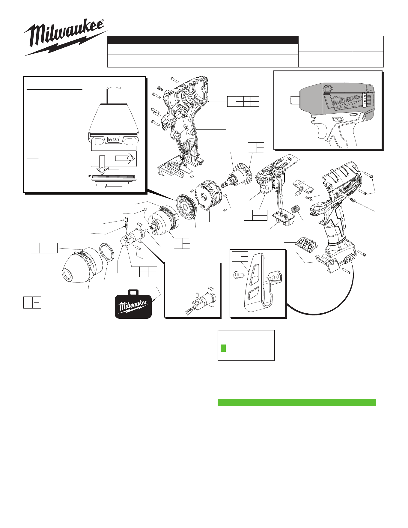
CATALOG NO. 2655-20
REVISED BULLETIN
54-26-2641
SPECIFY CATALOG NO. AND SERIAL NO. WHEN ORDERING PARTS
M18 FUEL™ 1/2" Square Impact Wrench
STARTING
SERIAL NO.
DATE
Jan. 2020
WIRING INSTRUCTION
E56C
EXAMPLE:
Component Parts (Small #)
Are Included When Ordering
The Assembly (Large #).
0
00
SEE PAGE 2
FIG. LUBRICATION
(Type 'J' Grease, No. 49-08-4220):
11c Lightly coat front washer surface of anvil (11c) with grease.
24,61 Lightly coat the I.D. of the ring gear (24) and the center of
the planet gears of impacting assembly with grease.
57 Coat inside of bushing inside front gearcase with grease.
59 Coat pinion of rotor assembly (59) with grease.
«
= Part number change from
previous service parts list.
«
Rubber Boot
No. 49-16-2754
(Optional)
For model
series 2654
and 2655
= 14-20-2656
Electronics Assy.
Assembly going ob-
solete. Replaced by:
FIG. PART NO. DESCRIPTION OF PART NO. REQ.
58 42-70-2653 Belt Clip Assembly (1)
59 16-07-2674 Rotor Assembly (1)
60 31-44-2670 Handle Assembly (1)
61 14-30-0095 Impacting Assembly (1)
62 14-20-2655 Electronics Assembly (1)
63 45-24-2655 Speed Selector (1)
66 42-06-0040 1/2" Square Anvil Assembly (1)
70 23-94-2115 U-Shaped Stamping/Wire Kit (Page 2) (1)
59
35
25
27
28
36
43
63
37
34
38
42
50
(9x)
46
(2x)
47
60
28 43 46
47 48 50
62
27 34
35 36
56
9 25
57
58
44
45
49
44
45
24
11c
12
61
24
57
9
3
2
19(2x)
66
2 3
4 11c
4
IMPORTANT NOTE: Gearcase end cap #25 is
LEFT HAND THREAD!
As an aid to assembly,
carefully lower the complete
front end of tool (gearcase /
impacting system) onto the
gearcase end cap. Gently
hand tighten front end
assembly onto gearcase
end cap. Be careful not
to cross-thread! Once
installed by hand, seat
gearcase end cap with a
good adjustable wrench
using light pressure.
Do not over tighten!
LEFT HAND THREAD
1
2
The original anvil
design shown here is
no longer available.
#66 Anvil Assembly
(42-06-0040)
must be
ordered
instead.
NOTE: Components of the impacting
assembly (61) can drop out of the
gearcase (57). Care must be
taken to hold those elements
in place when assembling
onto the gearcase end
cap (25).
67
59
60
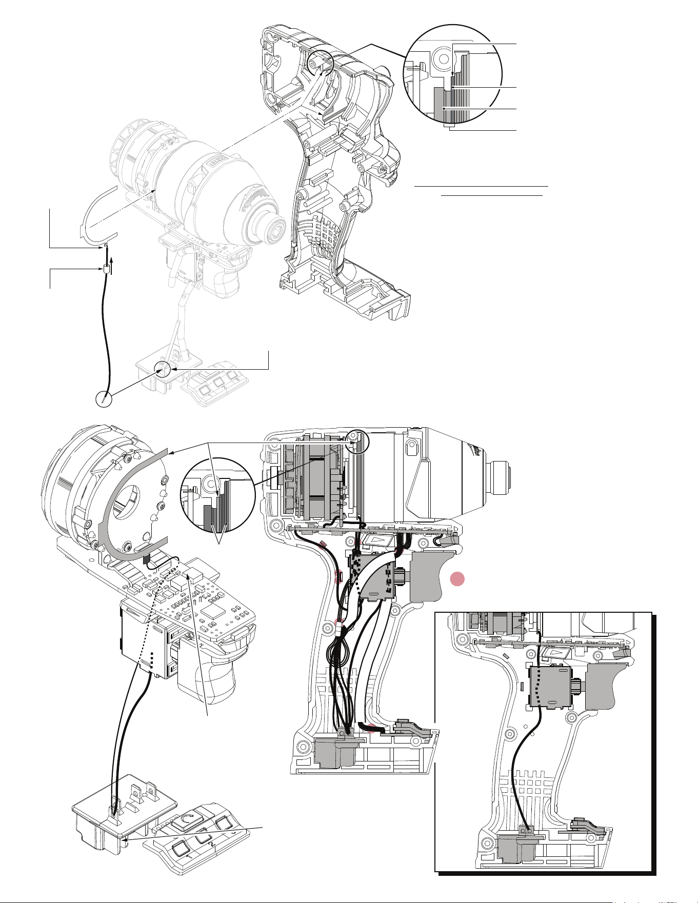
For ease of removal and installation of the High
Voltage protection system, it may be necessary
to remove the electronic/gearcase assemblies
from the left housing halve.
Recess in left housing halve for
U-Shaped Stamping
U-Shaped Stamping
(Grounding Plate)
Gearcase End Cap
Gearcase End Cap groove for
U-Shaped Stamping
Trim any excess
wire stranding.
Use a minimal
amount of
solder.
Slide heat
shrink tubing
over soldered
area and
shrink with
heat gun.
There may be heat shrink tubing
present on the existing negative
battery terminal that must be carefully
trimmed away prior to soldering on the HV wire.
Use a thin piece of electrical tape after soldering.
1. Place wire through hole on small tab of U-Shaped Stamping.
Twist metal strands to temporarily hold wire to stamping.
Trim any excess wire stranding. Be sure to position wire
straight down at the 6:00 position. Secure wire to stamping
with a minimal amount of solder to the strands. NOTE: Use
just enough solder to hold the High Voltage wire in place.
Excessive solder can directly affect the positioning of
the top housing halve!
2. Feed heat shrink tubing over wire and slide up over soldered
tab. Use a heat gun to heat tubing to tighten/shrink around
the soldered tab.
3. Position the HV wire to the left side, behind the PCBA
and behind the fwd./rev. shuttle.
4. Place U-Shaped Stamping onto groove of gearcase end cap
with small tab/wire positioned at the bottom. Be sure the U-
Shaped Stamping is properly seated in the recess of the left
housing halve. (See detail above).
5. Take loose end of kit wire and place metal wire strands
onto negative terminal of battery terminal block (front
right side with black wire attached to it).
NOTE: Heat shrink tubing may have to be carefully
removed. Secure that end with a minimal amount of
solder. Use a small piece of electrical tape to wrap
around the black negative wire and the black HV wire.
6. Press all electronic components in place and route all
wires in left housing halve according to wiring diagram.
Be sure all mechanical and electrical components are
rmlyseated.Besureallwiresarepressedrmlydown
in traps. Be sure that fwd./rev. shuttle and spring are
reinstalled and function properly.
7. Carefully install Right Housing
Halve being sure that there are no
interferences. Secure with existing
screws.
= WIRE TRAPS
or GUIDES
Route High Voltage Wire to the
left side of the PCBA and behind
the fwd/rev shuttle. Be sure that
the wire does not interfer with
the movement of the shuttle.
NOTE:
This view is shown
without gearcase
and housing halve
for clarity of HV
wire routing. Be
sure U-Shaped
Stamping is
placed over the
gearcase end cap
and against the
recess in the left
housing halve,
(See the detail
above).
U-Shaped Stamping
(Grounding Plate)
Solder the High Voltage Wire to
negative terminal of battery
connector block (along with black
wire from switch). Note: Heat
shrink tubing will have to be
carefully trimmed away prior to
soldering. After wire is soldered,
wrap a thin piece of electrical tape
around the two wires and terminal.
Gearcase End Cap