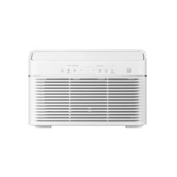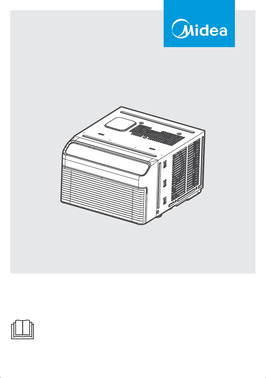
MAW08V1YWT-S
MAW12V1YWT-S
USER MANUAL
Warning notices: Before using this product, please read this manual carefully and keep it for future
reference. For additional support, please call customer service at 1-866-646-4332.
The design and specifications are subject to change without prior notice for product improvement.
Consult with the dealer or the manufacturer for details.
Inverter Window

THANK YOU LETTER
Thank you for choosing Midea! Before using your new Midea product, please read this manual
thoroughly to ensure that you know how to operate the features and functions that your new air
conditioner offers in a safe way.
OWNER’S MANUAL
• For support, please call the Service Center at 1-866-646-4332.
• This unit is not intended for use by people (including children) with reduced
physical, sensory, or mental capabilities or lack of experience and knowledge,
unless they have been given supervision or instruction concerning use of the
unit by a person responsible for their safety.
• Children should be supervised to ensure that they do not play with the unit.
• The unit shall be installed in accordance with national wiring regulations.
• Do not operate the air conditioner in a humid room such as a bathroom or laundry
room.
CAUTION
SAFETY PRECAUTIONS .......................................................................................3
INSTALLATION INSTRUCTIONS .......................................................................14
OPERATING INSTRUCTIONS .............................................................................21
CLEANING & MAINTENANCE ...........................................................................26
TROUBLESHOOTING TIPS .................................................................................27
REMOTE CONTROL AND APP INSTRUCTIONS ..........................................29
WARRANTY .............................................................................................................46
2
This manual provides valuable information on the proper use and maintenance of an
air conditioner. With a small amount of preventive care, significant time and money
can be saved throughout the lifespan of the unit. Troubleshooting tips are included
to address common issues, many of which can be resolved quickly without the need
for professional service. While these instructions cover a wide range of scenarios, they
may not address every possible condition of use. Therefore, it is essential to exercise
common sense and prioritize safety during installation, operation, and maintenance of
the air conditioner.
Read these operating instructions carefully and attentively before using/commis-
sioning the unit and keep them in the immediate vicinity of the installation site or
unit for later use!
WARNING
The signal word indicates a hazard with a medium level of risk
which, if not avoided, may result in death or serious injury.
CAUTION
The signal word indicates a hazard with a low degree of risk which,
if not avoided, may result in minor or moderate injury.
Explanation of Symbols
WARNING
•
•
•
•
•
•
•
•
•
•
•
Plug in power plug properly. Otherwise, it may cause electric shock or fire due to
excess heat generation.
Do not operate or stop the unit by inserting or pulling out the power plug. It may
cause electric shock or fire due to heat generation.
Do not damage or use an unspecified power cord. It may cause electric shock or fire.
If the power cord is damaged, it must be replaced by the manufacturer or an
authorised service centre or a similarly qualified person in order to avoid a hazard.
Do not operate with wet hands or in damp environment. It may cause electric shock.
Do not allow water to run into electric parts. It may cause failure of machine of
electric shock.
Do not modify power cord length. It may cause electric shock or fire due to
heat generation.
Do not use the socket if it is loose or damaged. It may cause fire and electric shock.
Unplug the unit if strange sounds, smell, or smoke comes from it. It may cause fire
and electric shock.
Do not disassemble or modify unit. It may cause failure and electric shock.
Do not open the unit during operation. It may cause electric shock.
SAFETY PRECAUTIONS
3
WARNING
•
•
•
•
•
•
In North America, installation must be performed in accordance with the require-
ment of NEC and CEC by authorized personnel only).
Always install circuit breaker and a dedicated power circuit. Incorrect installation
may cause fire and electric shock.
Do not direct airflow at room occupants only. This could damage your health.
Do not use the power cord near flammable gas or combustibles, such as gasoline,
benzene, thinner, etc. It may cause an explosion or fire.
Keep firearms away. It may cause fire.
Do not use the power cord close to heating appliances. It may cause fire and
electric shock.
Ventilate room before operating air conditioner if there is a gas leakage from
another appliance. It may cause explosion, fire and, burns.
CAUTION
•
•
•
•
•
•
•
•
•
•
•
•
•
•
•
•
•
•
•
This unit is not intended for use by people (including children) with reduced physical,
sensory, or mental capabilities or lack of experience and knowledge, unless they have
been given supervision or instruction concerning use of the unit by a person
responsible for their safety.
Children should be supervised to ensure that they do not play with the appliance.
If the power cord is damaged, it must be replaced by the manufacturer, its service
agent, or similarly qualified person in order to avoid a hazard.
The unit shall be installed in accordance with national wiring regulations.
Do not operate your air conditioner in a wet room such as a bathroom or laundry
room.
The unit with electric heater shall have at least 1 meter of space to the nearest
combustible material.
C
ontact the authorized service technician for repair or maintenance of this unit.
When the air filter is to be removed, do not touch the metal parts of the unit. It may
cause an injury.
Do not put a pet or house plant where it will be exposed to direct air flow. This
could injure the pet or plant.
Ventilate the room well when used together with a stove, etc. An oxygen shortage
may occur.
Do not use strong detergent such as wax or thinner but use a soft cloth. Appearance
may be deteriorated due to change of product color or scratching of its surface.
Do not clean the air conditioner with water. Water may enter the unit and degrade
the insulation. It may cause an electric shock.
Do not use for special purposes. Do not use this air conditioner to preserve
precision devices, food, pets, plants, and art objects. lt may cause deterioration of
quality, etc.
Stop operation and close the window in storm or hurricane. Operation with
windows opened may cause wetting of indoor and soaking of household furniture.
clean unit when power is on as it may cause fire and electric shock, it may cause an
injury.
Ensure that the installation bracket of the outdoor appliance is not damaged due to
prolonged exposure. If bracket is damaged, there is concern of damage due to
falling of unit.
Always insert the filters securely. Clean filter once every two weeks. Operation
without filters may cause failure.
Do not place obstacles around air-inlets or inside of air-outlet. It may cause failure
of appliance or accident.
Hold the plug by the head of the power plug when taking it out. It may cause
electric shock and damage.
4
•
•
•
•
•
Do not place heavy object on the power cord and ensure that the cord is not
compressed. There is danger of fire or electric shock.
It may cause failure of product or fire.
Do not drink water drained from air conditioner. It contains contaminants and could
make you sick.
Use caution when unpacking and installing. Sharp edges could cause injury.
circuit breaker. Isolate supply by taking the power-plug out and contact a qualified
service technician.
CAUTION
NOTE
The power supply cord with this air conditioner contains a current detection device
designed to reduce the risk of fire. Please refer to the section Operation of Current
Device for details. In the event that the power cord is damaged, it cannot be
repaired – it must be replaced with a cord from the product manufacturer.
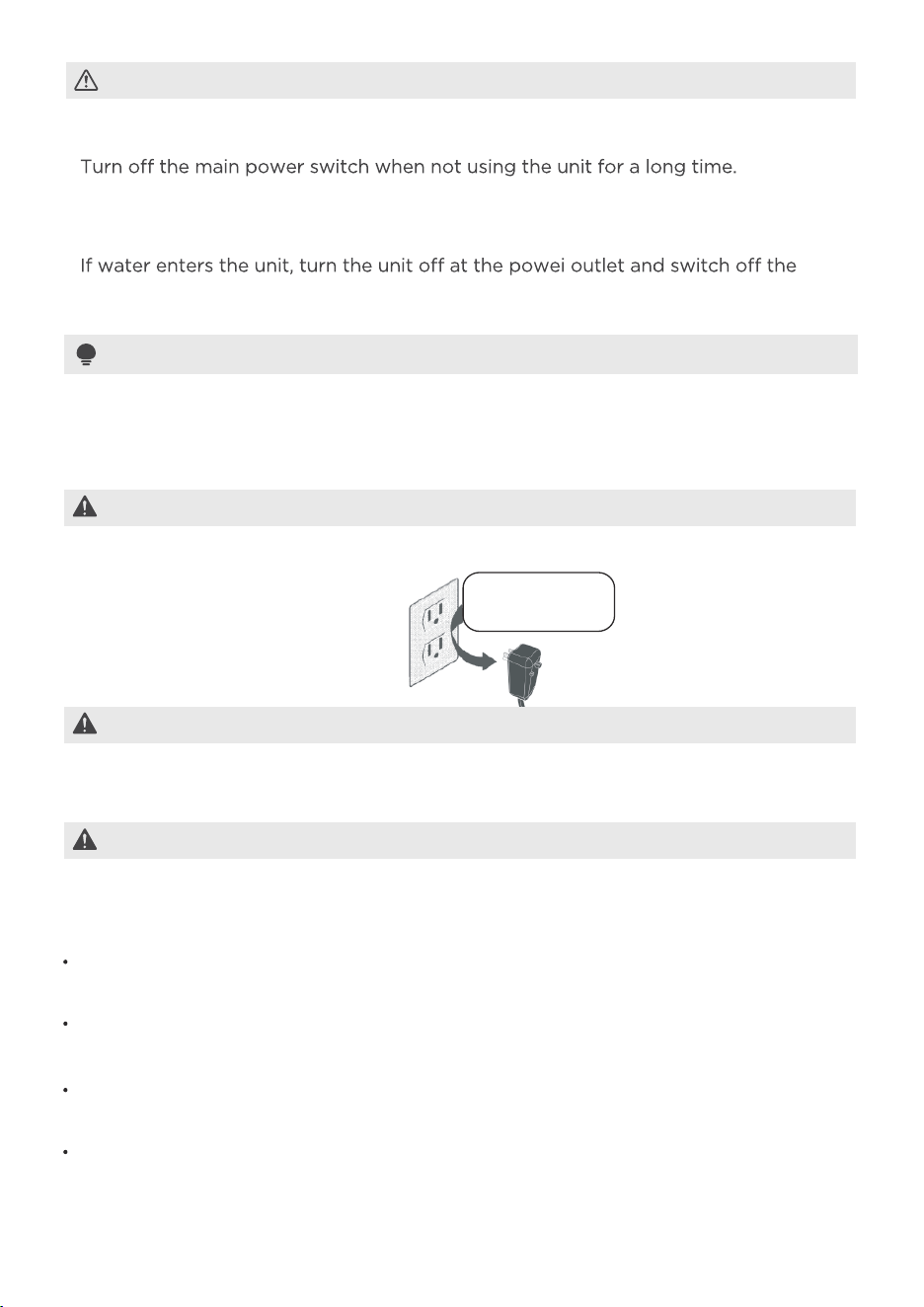
WARNING
Avoid fire hazard or electric
shock. Do not use an extension
cord or an adapter plug. Do
not remove any prongs from
the power cord.
WARNING
Grounding type wall receptacle
Do not, under any
circumstances, cut,
remove, or bypass
the grounding prongs.
Power supply cord with
3-prong grounding plug
and current detection
device.
Do not store or use gasoline or other flammable vapors and liquids in the vicinity of
this or any other appliance.
For Your Safety
To reduce the risk of fire, electrical shock, or injury when using your air conditioner,
follow basic precautions, including the following:
Be sure the electrical service is adequate for the model you have chosen. This
information can be found on the serial plate, which is located on the side of the the
cabinet and behind the grille.
It is recommended to clean both sides of the window glass first. If the window has
a screen panel included on the lower portion, the screen panel should be removed
before installation.
Be sure the air conditioner has been securely and correctly installed according to
the installation instructions in this manual. Save this manual for possible future use
in removing or installing this unit.
When handling the air conditioner, be careful to avoid cuts from the sharp metal
fins on the front and rear coils.
Prevent Accidents
5
WARNING
The complete electrical rating of your new room air conditioner is stated on the serial
plate. Refer to the rating when checking the electrical requirements.
Be sure the air conditioner is properly grounded. To minimize shock and fire
hazards, proper grounding is important. The power cord is equipped with a
three-prong grounding plug for protection against shock hazards.
The air conditioner must be used in a properly grounded wall receptacle. If the wall
receptacle you intend to use is not adequately grounded or protected by a time
delay fuse or circuit breaker, have a qualified electrician install the proper receptacle.
Ensure the receptacle is accessible after the unit installation.
Do not run air conditioner without side protective cover in place.This could result in
mechanical damage within the air conditioner.
Do not use an extension cord or an adapter plug.
Electrical Information
Operation of Current Device
(Applicable to only units with a current detection device)
The power supply cord contains a current device that senses damage to the power
cord. To test your power supply cord do the following:
1. Plug in the Air Conditioner.
2. The power supply cord will have TWO buttons on the plug head. Press the TEST
button, you will notice a click as the RESET button pops out.
3. Press the RESET button, again you will notice a click as the button engages.
4. The power supply cord is now supplying electricity to the unit. On some products,
this is also indicated by a light on the plug head.
NOTICE
Always make sure the RESET button is pushed in for correct operation.
The power supply cord must be replaced if it fails to reset when either the TEST
button is pushed or if it cannot be reset. A new one can be obtained from the
product manufacturer.
If power supply cord is damaged, it cannot be repaired. It MUST be replaced by
one obtained from the product manufacturer.
NOTE: This air conditioner can not be as a primary heat source; This air
conditioner is designed to be operated under the following conditions:
Cooling
operation
Outdoor
temp:
Indoor
temp:
64-109 /18-43 (64-125 /18-52
for special tropical models)
60-90
/
16-32
• Performance may be reduced outside of these operating temperatures.
-
ing from cool to fan and back to cool. This prevents damage from occurring to the
compressor.
• The relative humidity of the room should be less than 80%. If the unit is used in a
condition with a relative humidity over 80%, there will be condensed water on the
surface of the unit.
6
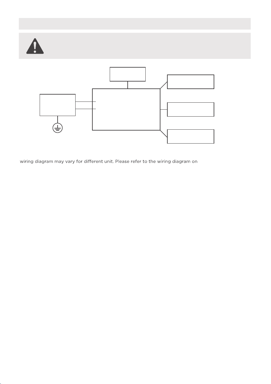
Electronic Work
WARNING:
BEFORE PERFORMING ANY ELECTRICAL OR WIRING WORK, TURN OFF THE
MAIN POWER TO THE SYSTEM.
Main Control
Compressor
Fan Motor
Display
Power
Supply
L/AC L/L1/L-IN
N/AC N/L2/N-IN
Other
Electronic Type
NOTE:
Please strictly follow the wiring label attached to the machine for all wiring connections. The
the machine you have purchased. The above wiring diagram is a simplified version for preliminary
illustration purposes only.
7
WARNING
CAUTION: Risk of fire
flammable materials
IMPORTANT NOTE:Read this manual carefully
before installing or operating your new appliance unit.
Make sure to save this manual for future reference.
A2L
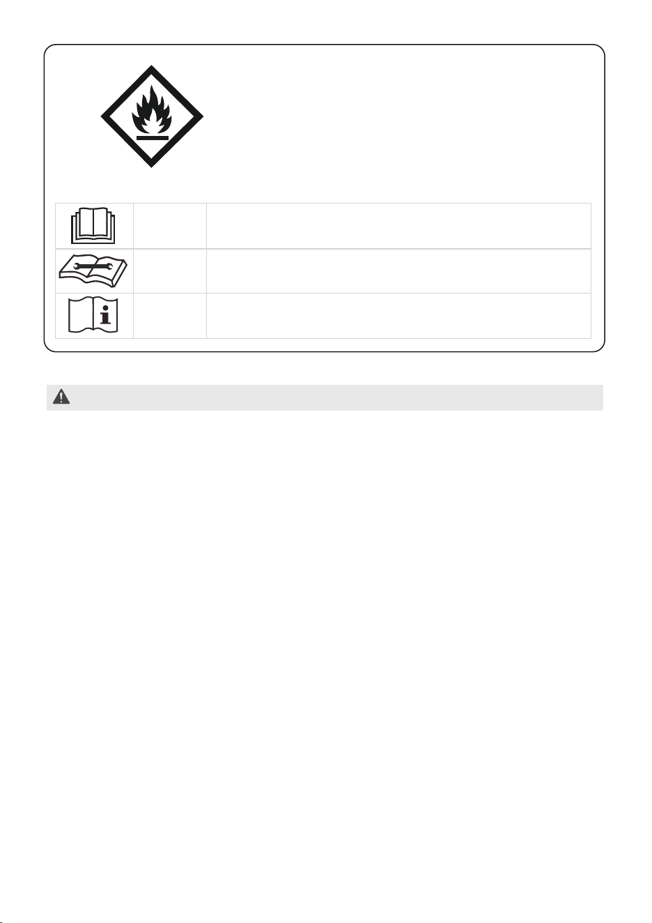
CAUTION
This symbol indicates that the operation manual should
be read carefully.
CAUTION
This symbol indicates that a service personnel should
be handling this unit with reference to the
installation manual.
CAUTION
This symbol indicates that information is available such
as the operating manual or installation manual.
Explanation of symbols displayed on the unit
-Servicing shall only be performed as recommended by the manufacturer.
Maintenance and repair requiring the assistance of other skilled personnel shall be
carried out under the supervision of the person competent in the use of flammable
refrigerants.
-DO NOT modify the length of the power cord or use an extension cord to power
the unit.
-DO NOT share a single outlet with other electrical appliances. Improper power
supply can cause fire or electrical shock.
-Please follow the instruction carefully to handle, install, clear, service the unit to
avoid any damage or hazard.
Flammable
Refrigerant R32 is used within appliance.
-When maintaining or disposing the unit, the refrigerant (R32) shall be recovered
properly, shall not discharge to air directly.
-Compliance with national gas regulations shall be observed.
-Keep ventilation openings clear of obstruction.
-The unit shall be stored so as to prevent mechanical damage from occurring.
-The unit shall be stored in a well-ventilated area where the room size
corresponds to the room area as specified for operation.
-Any person who is involved with working on or breaking into a refrigerant circuit
should hold a current valid certificate from an industry-accredited assessment
authority, which authorises their competence to handle refrigerants safely in
accordance with an industry recognised assessment specification. All training shall
follow the ANNEX HH requirements of UL 60335-2-40 4th Edition.
8
Examples for such working procedures are:
• breaking into the refrigerating circuit;
• opening of sealed components;
• opening of ventilated enclosures.
-No open fire or device like switch which may generate spark/arcing shall be
around unit to avoid causing ignition of the flammable refrigerant used.
Please follow the instructions carefully when storing or maintaining the appliance to
prevent mechanical damage from occurring.
-Do not use means to accelerate the defrosting process or to clean, other than those
recommended by the manufacturer.
-The unit shall be stored in a room without continuously operating ignition sources
(i.e.: open flames, an operating gas appliance) and ignition sources or (i.e.: an
operating electric heater) close to the appliance.
-Do not pierce or burn.
-Be aware that the refrigerants may not contain an odor.
1. Transport of equipment containing flammable refrigerants
See transport regulations.
2. Marking of equipment using signs
See local regulations.
3. Disposal of equipment using flammable refrigerants
See national regulations.
4. Storage of equipment/appliances
The storage of the unit should be in accordance with the applicable regulations
or instructions, whichever is more stringent.
5. Storage of packed (unsold) equipment
Storage package protection should be constructed such that mechanical damage
to the unit inside the package will not cause a leak of the refrigerant charge.
The maximum number of pieces of equipment permitted to be stored together
will be determined by local regulations.
6. Information on servicing
1) Checks to the area
Prior to beginning work on systems containing flammable refrigerants, safety
checks are necessary to ensure that the risk of gnition is minimized. For repair to
the refrigerating system, the following precautions shall be complied with prior to
conducting work on the system.
2) Work procedure
Work shall be undertaken under a controlled procedure so as to minimize the risk
of a flammable gas or vapour being present while the work is being performed.
3) General work area
the nature of work being carried out. Work in confined spaces shall be avoided.
within the area have been made safe by control of flammable material.
9
4) Checking for presence of refrigerant
The area shall be checked with an appropriate refrigerating detector prior to and
during work, to ensure the technician is aware of potentially flammable
atmospheres. Ensure that the leak detection equipment being used is suitable for
use with flammable refrigerants, i.e. non-sparking, adequately sealed or
intrinsically safe.
5) Presence of fire extinguisher
If any hot work is to be conducted on the refrigeration equipment or any
associated parts, appropriate fire extinguishing equipment shall be available to
hand. Have a dry powder or CO2 fire extinguisher adjacent to the charging area.
6) No ignition sources
No person carrying out work in relation to a refrigerating system which involves
exposing any pipe work that contains or has contained flammable refrigerant
shall use any sources of ignition in such a manner that it may lead to the risk of
fire or explosion. All possible ignition sources, including cigarette smoking,
removing and disposal, during which flammable refrigerant can possibly be
released to the surrounding space. Prior to work taking place, the area around the
equipment is to be surveyed to make sure that there are no flammable hazards or
ignition risks. "No Smoking" signs shall be displayed.
7) Ventilated area
Ensure that the area is in the open or that it is adequately ventilated before
breaking into the system or conducting any hot work. A degree of ventilation shall
continue during the period that the work is carried out. The ventilation should
safely disperse any released refrigerant and preferably expel it externally into the
atmosphere.
8) Checks to the refrigerating equipment
Where electrical components are being changed, they shall be fit for the purpose
and to the correct specifications. At all times the manufacturer's maintenance and
service guidelines shall be followed. If in doubt consult the manufacturer’s
technical department for assistance. The following checks shall be applied to
installations using flammable refrigerants: the actual refrigerant charge is in
accordance with the room size within which the refrigerant containing parts are
installed; the ventilation machinery and outlets are operating adequately and are
not obstructed; if an indirect refrigerating circuit is being used, the secondary
circuit shall be checked for the presence of refrigerant; marking to the unit
continues to be visible and legible. markings and signs that are illegible shall be
corrected; and refrigerating pipe or components are installed in a position where
they are unlikely to be exposed to any substance which may corrode refrigerant
containing components, unless the components are constructed of materials
which are inherently resistant to being corroded or are suitably protected against
being so corroded.
10
-Continuously flush or purge with inert gas when using flame to open circuit; and
-Open the circuit.
9) Checks to electrical devices
Repair and maintenance to electrical components shall include initial safety checks
and component inspection procedures. If a fault exists that could compromise
safety, then no electrical supply shall be connected to the circuit until it is
satisfactorily dealt with. If the fault cannot be corrected immediately but it is
necessary to continue operation, an adequate temporary solution shall be used.
This shall be reported to the owner of the equipment so all parties are advised.
Initial safety checks shall include:
That capacitors are discharged: this shall be done in a safe manner to avoid
possibility of sparking; that there no live electrical components and wiring are
e
xposed while charging, recovering or purging the system; that there is continuity
of earth bonding.
7. Sealed electrical components shall be replaced.
8. Intrinsically safe components must be replaced.
9. Cabling
Check that cabling will not be subject to wear, corrosion, excessive pressure,
sources such as compressors or fans.
10. Detection of flammable refrigerants
Under no circumstances shall potential sources of ignition be used in the
searching for or detection of refrigerant leaks. A halide torch (or any other
detector using a naked flame) shall not be used.
The following leak detection methods are deemed acceptable for systems
containing flammable refrigerants. Electronic leak detectors shall be used to
detect flammable refrigerants, but the sensitivity may not be adequate, or may
need re-calibration. (Detection equipment shall be calibrated in a refrigerant-free
area.) Ensure that the detector is not a potential source of ignition and is suitable
for the refrigerant used. Leak detection equipment shall be set at a percentage
of the LFL of the refrigerant and shall be calibrated to the refrigerant employed
and the appropriate percentage of gas (25% maximum) is confirmed. Leak
detection fluids are suitable for use with most refrigerants but the use of
detergents containing chlorine shall be avoided as the chlorine may react with
the refrigerant and corrode the copper pipe-work. If a leak is suspected, all
naked flames shall be removed/extinguished. If a leakage of refrigerant is found
which requires brazing, all of the refrigerant shall be recovered from the system,
leak. Removal of refrigerant shall be according to Removal and evacuation.
11. Removal and evacuation
When breaking into the refrigerant circuit to make repairs—or for any other
purpose - conventional procedures shall be used. However, for flammable
refrigerants it is important that best practice be followed, since flammability is a
consideration. The following procedure shall be adhered to:
-Safely remove refrigerant following local and national regulations;
-Evacuate;
-Purge the circuit with inert gas (optional for A2L);
-Evacuate (optional for A2L);
11
12
12. Charging procedures
In addition to conventional charging procedures, the following requirements shall
when using charging equipment. Hoses or lines shall be as short as possible to
minimize the amount of refrigerant contained in them. Cylinders shall be kept in
an appropriate position according to the instructions. Ensure that the
refrigeration system is earthed prior to charging the system with refrigerant.
Label the system when charging is complete (if not already). Extreme care shall
be taken not to overfill the refrigeration system. Prior to recharging the system it
shall be pressure tested with OFN. The system shall be leak tested on completion
charging but prior to commissioning. A follow up leak test shall be carried out
prior to leaving the site.
13.
Decommissioning
Before carrying out this procedure, it is essential that the technician is completely
familiar with the unit and all its detail. It is recommended good practice that all
refrigerants are recovered safely. Prior to the task being carried out, an oil and
refrigerant sample shall be taken in case analysis is required prior to re-use of
reclaimed refrigerant. It is essential that electrical power is available before the
task is commenced.
a) Become familiar with the unit and its operation.
b) Isolate system electrically.
c) Before attempting the procedure ensure that: mechanical handling equipment is
available, if required, for handling refrigerant cylinders; all personal protective
equipment is available and being used correctly; the recovery process is supervised
at all times by a competent person; recovery equipment and cylinders conform to the
appropriate standards.
d) Pump down refrigerant system, if possible.
e) If a vacuum is not possible, make a manifold so that refrigerant can be removed from
various parts of the system.
f ) Make sure that cylinder is situated on the scales before recovery takes place.
g) Start the recovery machine and operate in accordance with instructions.
h) Do not overfill cylinders. (No more than 80% volume liquid charge.)
i ) Do not exceed the maximum working pressure of the cylinder, even temporarily.
The refrigerant charge shall be recovered into the correct recovery cylinders if
venting is not allowed by local and national codes. For appliances containing
flammable refrigerants, the system shall be purged with oxygen-free nitrogen to
render the appliance safe for flammable refrigerants. This process might need t
o
be repeated several times. Compressed air or oxygen shall not be used for purg-
ing refrigerant systems.For appliances containing flammable refrigerants, refrig-
erants purging shall be achieved by breaking the vacuum in the system with
oxygen-free nitrogen and continuing to fill until the working pressure is achieved,
then venting to atmosphere, and finally pulling down to a vacuum (optional for
A2L). This process shall be repeated until no refrigerant is within the system
(optional for A2L). When the final oxygen-free nitrogen charge is used. the
system shall be vented down to atmospheric pressure to enable work to take
place. The outlet for the vacuum pump shall not be close to any potential ignition
sources, and ventilation shall be available.
13
j) When the cylinders have been filled correctly and the process completed, make sure
that the cylinders and the equipment are removed from site promptly and all isolation
k) Recovered refrigerant shall not be charged into another refrigeration system unless it
has been cleaned and checked.
14. Labeling
Equipment shall be labelled stating that it has been de-commissioned and emptied
of refrigerant. The label shall be dated and signed. Ensure that there are labels on
the equipment stating the equipment contains flammable refrigerant.
15. Recovery
When removing refrigerant from a system, either for servicing or decommissioning,
it is recommended good practice that all refrigerants are removed safely.
When
transferring refrigerant into cylinders, ensure that only appropriate refrigerant
recovery cylinders are employed. Ensure that the correct number of cylinders for
holding the total system charge is available. All cylinders to be used are designated
for the recovered refrigerant and labelled for that refrigerant (i.e., special cylinders for
the recovery of refrigerant). Cylinders shall be complete with pressure-relief valve and
evacuated and, if possible, cooled before recovery occurs. The recovery equipment
shall be in good working order with a set of instructions concerning the equipment
that is at hand and shall be suitable for the recovery of the flammable refrigerant.
If in doubt, the manufacturer should be consulted. In addition, a set of calibrated
weighing scales shall be available and in good working order. Hoses shall be
complete with leak-free disconnect couplings and in good condition.
The
recovered refrigerant shall be processed according to local legislation in the
correct recovery cylinder, and the relevant waste transfer note arranged. Do not
mix refrigerants in recovery units and especially not in cylinders.
If compressors
or compressor oils are to be removed, ensure that they have been evacuated to
an acceptable level to make certain that flammable refrigerant does not remain
within the lubricant. The compressor body shall not be heated by an open flame
or other ignition sources to accelerate this process. When oil is drained from a
system, it shall be carried out safely.
14
INSTALLATION INSTRUCTIONS
WARNING
Read these instructions completely
and carefully.
• IMPORTANT - Save these instructions.
• IMPORTANT - Observe all governing
codes and ordinances.
It is recommended that two people
install this product.
Proper installation is the responsibility
of the installer.
Product failure due to improper
installation is not covered under the
Limited Warranty.
All supplied parts must be used, and
proper installation procedures, as
outlined in these instructions, must
be followed when installing the air
conditioner.
Do not, under any circumstances, cut
or remove the third (ground) prong
from the power cord.
Do not change the plug on the power
cord of the air conditioner.
Aluminum house wiring may present
special problems - consult a qualified
electrician.
When handling the air conditioner, be
careful to avoid cuts from sharp metal
edges and aluminum fins on front and
rear coils. Please wear cut-resistant
gloves.
Bracket should only be used for
its intended purpose. If not, the
warranty will be voided.
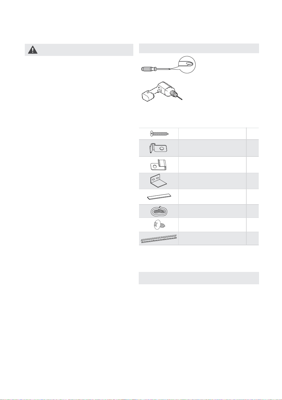
Tools Needed
NOTICE
• SAVE CARTON and these
INSTALLATION INSTRUCTIONS for
future reference. The carton is the best
to store unit during winter, or when not
in use.
• DO NOT USE ANY SCREWS OTHER
THAN THOSE SPECIFIED HERE.
• FOR SAFETY REASONS, THE TOP RAIL
MUST BE SECURELY FASTENED WITH
ALL FOUR (4) SCREWS.
Installation Hardware
Some assembly is required. Please read these
instructions carefully.
Phillips
Screwdriver
Drill
(If pilot holes are needed)
4
1
3/8” Screws
Top Rail
2
1
Window sash seal foam
Weather stripping
(10”×1-1/2”×1/6”)
1Sash lock
2
Lock frame
(For Vinyl-Clad windows)
2
Lock frame
(For Wooden windows)
7
1/2” Screws
15
2 .giF1 .giF
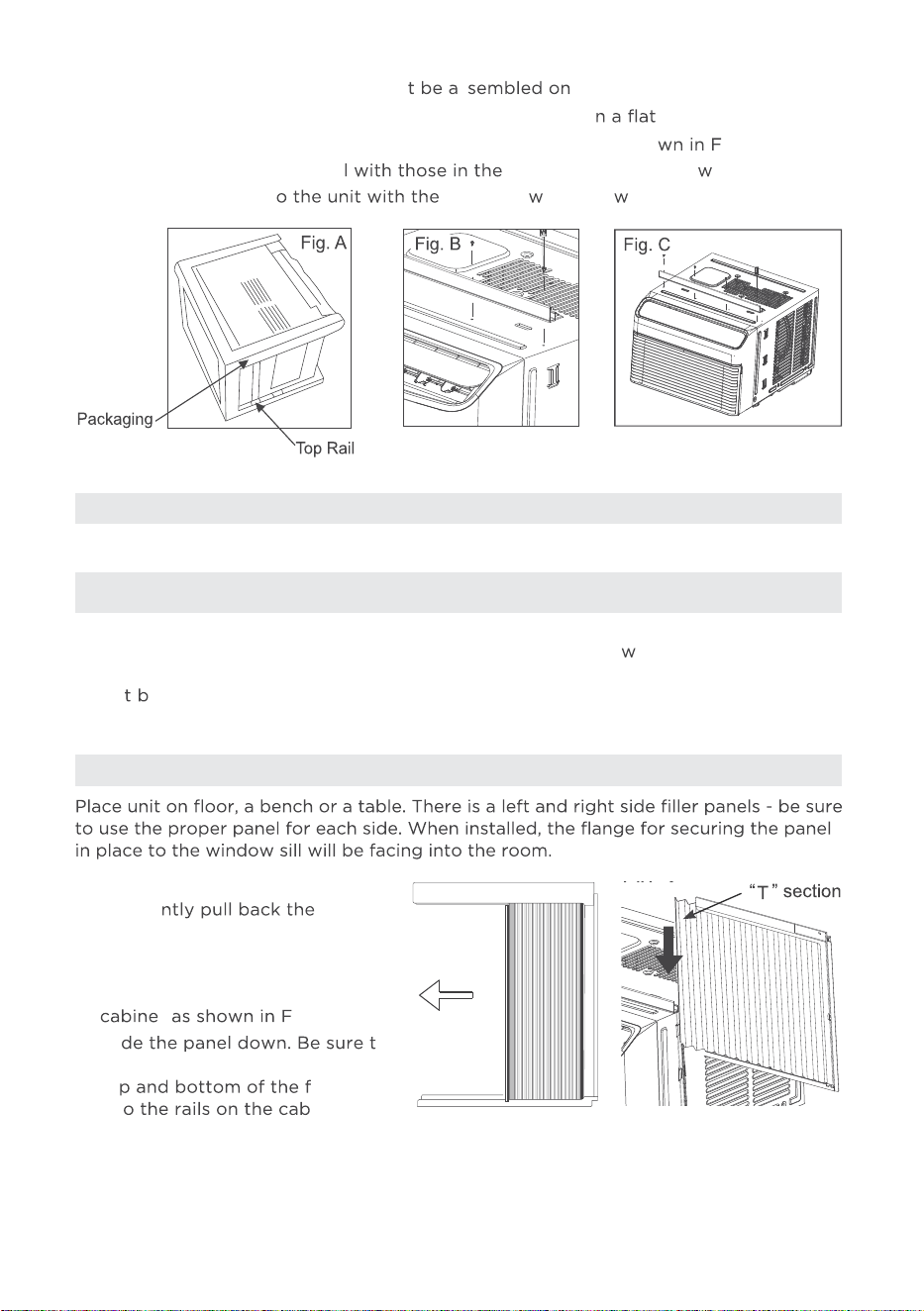
LEFT + RIGHT FILLER PANEL ASSEMBLY
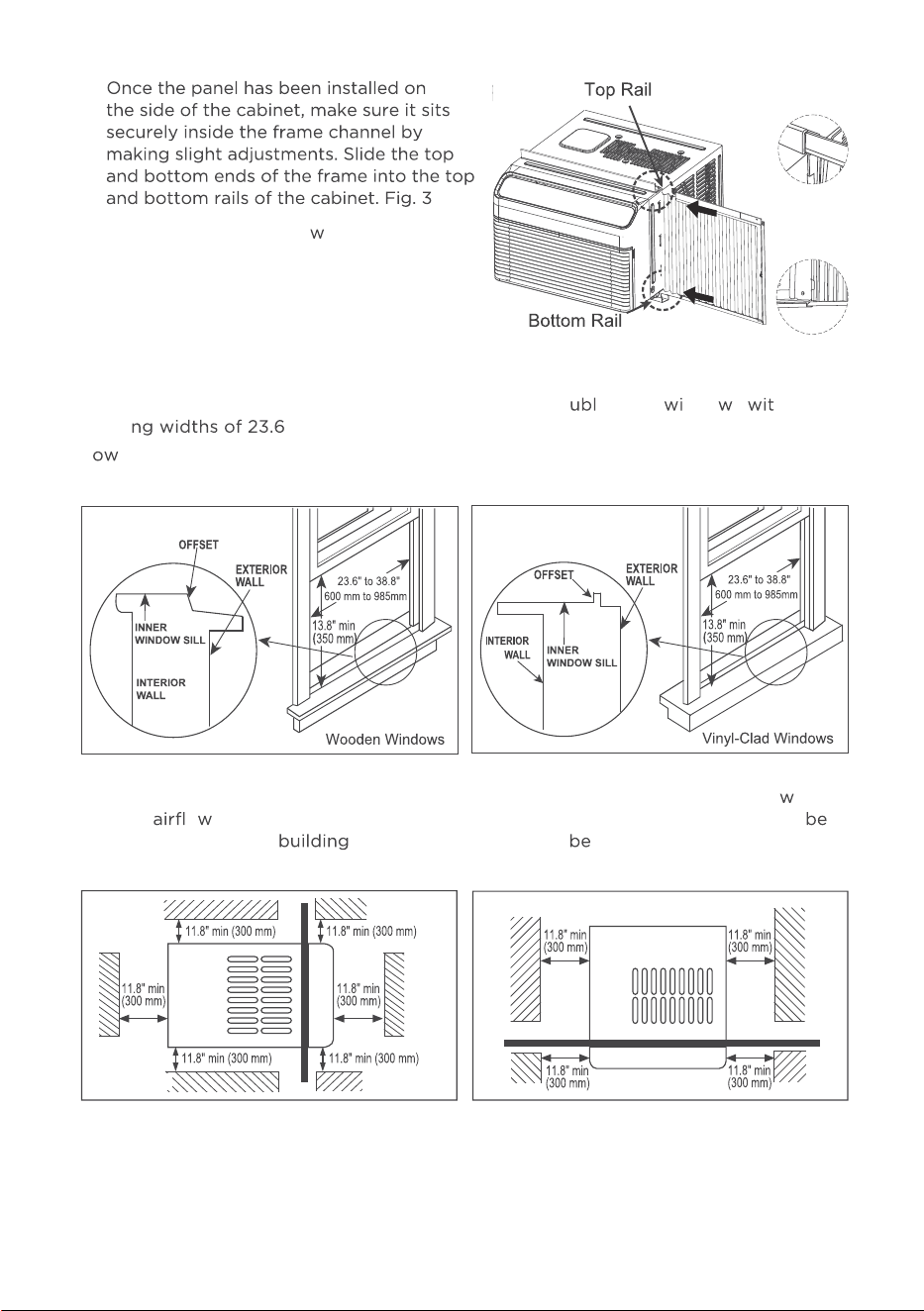
Installation
1. Install Side Filler Panels
Before installing unit, the top rail mus s the unit.
A: Remove the air conditioner from the carton and place o surface.
B: Remove top rail from the rear of the packaging material as sho
ig. A.
C: Align the hole in the top rai top of the unit as sho n in Fig. B.
D: Secure the top rail t 3/8” Scre s as sho n in Fig. C.
NOTICE
Top Rail and Side Panels at each side are offset to provide the proper pitch to
the rear of (5/16”). This is necessary for proper condensed
ater utilization and
drainage. If you are not using the Side Panels for any reason, this pitch to the rear
mus e maintained!
A. Hold the side panel in one hand
and ge center
to free the open end. See Fig. 1.
B. Slide the free and “T” section
of the panel directly into the
t ig. 2.
Sli
o
leave enough space to slip the
to
rame
int inet.
16
C.
.
D. Slide the panel all the
ay in and repeat
on the other side.
Fig. 2
The air conditioner is designed to install in standard do e hung ndo s h
openi to 38.8 inches (600 mm to 985mm) (Fig. 4A, Fig. 4B).
L er sash must open sufficiently to allow a clear vertical opening of 13.8 inches
(350 mm).
Side louvers and the rear of the air conditioner must have clear air space to allo
enough o through the condenser, for heat removal. The rear of the unit must
outdoors, not inside a or garage. There should at least 11.8 inches (300 mm)
clearance around the unit. See Fig. 4C & Fig. 4D.
Fig. 4A
Fig. 4B
Outdoor side
Outdoor side
Indoor side
Indoor side
Fig. 4C Fig. 4D
17
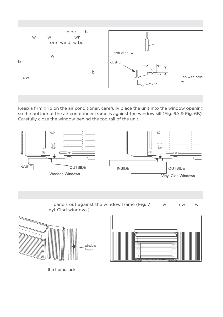
If the air conditoner is ked y Storm
Windo , add ood as sho in Fig.
5, or remove st o fore air
conditioner is installed.
If Storm Windo
Frame must remain,
e sure the drain holes or slots are not
caulked or painted shut. Accumulated
Rain Water or Condensation must e
all ed to drain out.
Extend the side A for oode indo s),
(Fig. 7B for Vi .
2. Storm Window
3. Place the Unit Into the Window
4. Extend the Side Panels
SASH
1-1/2"min
(38 mm)
Board thickness
as required, for
proper pitch to rear,
along entire
sill. Fast
or scre s.
St
o
frame or other
ction.
Fig. 5
y
Fig. 6A
Fig. 6B
Fig. 7A
Fig. 7B
18
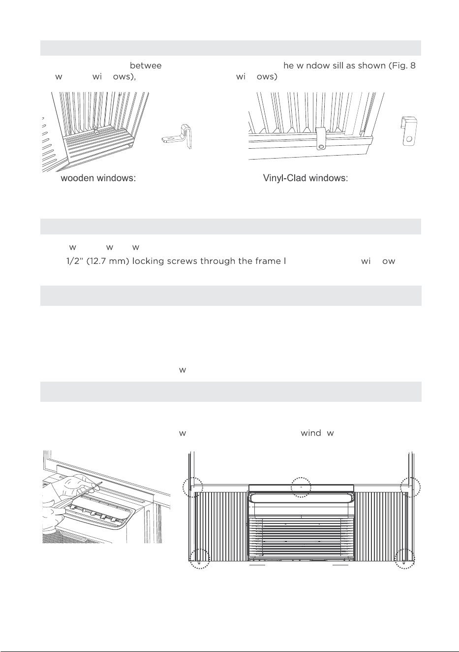
5. Install the Frame Lock
6. Drive Locking Screws
Place the frame lock n the frame extensions and t i A
for ooden nd (Fig. 8B for Vinyl-Clad nd .
A: For ooden indo s:
Drive
ock and into the nd sash
(Fig. 9B).
Fig. 8A
Fig. 8B
Fig. 9A
Fig. 9B
NOTICE
Before driving the screws, use a drill to drill 5 holes through the holes in the
frame lock and frame extensions into the windows sash as shown ( Fig. 9B).
NOTICE
To prevent window sill from splitting, drill 1/8” (3mm) pilot holes before driving screws.
B: For Vinyl-Clad windows:
Drive 1/2” (12.7 mm) locking scre
s through the frame lock and into the sill (Fig. 9A).
Drive 1/2” (12.7 mm) locking scre
s through frame holes into o sash (Fig. 9B).
19
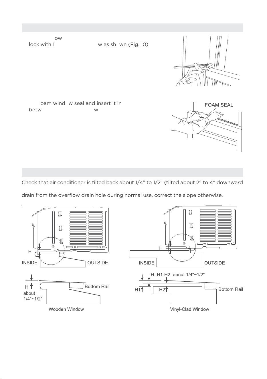
7. Secure Lower Sash
8. Check Installation
A: To secure l
er sash in place, attach right angle sash
/2”(12.7 mm) scre o .
to the outside, see Fig. 12A & Fig. 12B). After proper installation, condensate, should not
B: Cut f o to the space
een the upper and lo er sashes (Fig. 11).
B21 .giFA21 .giF
Fig. 10
Fig. 11
20
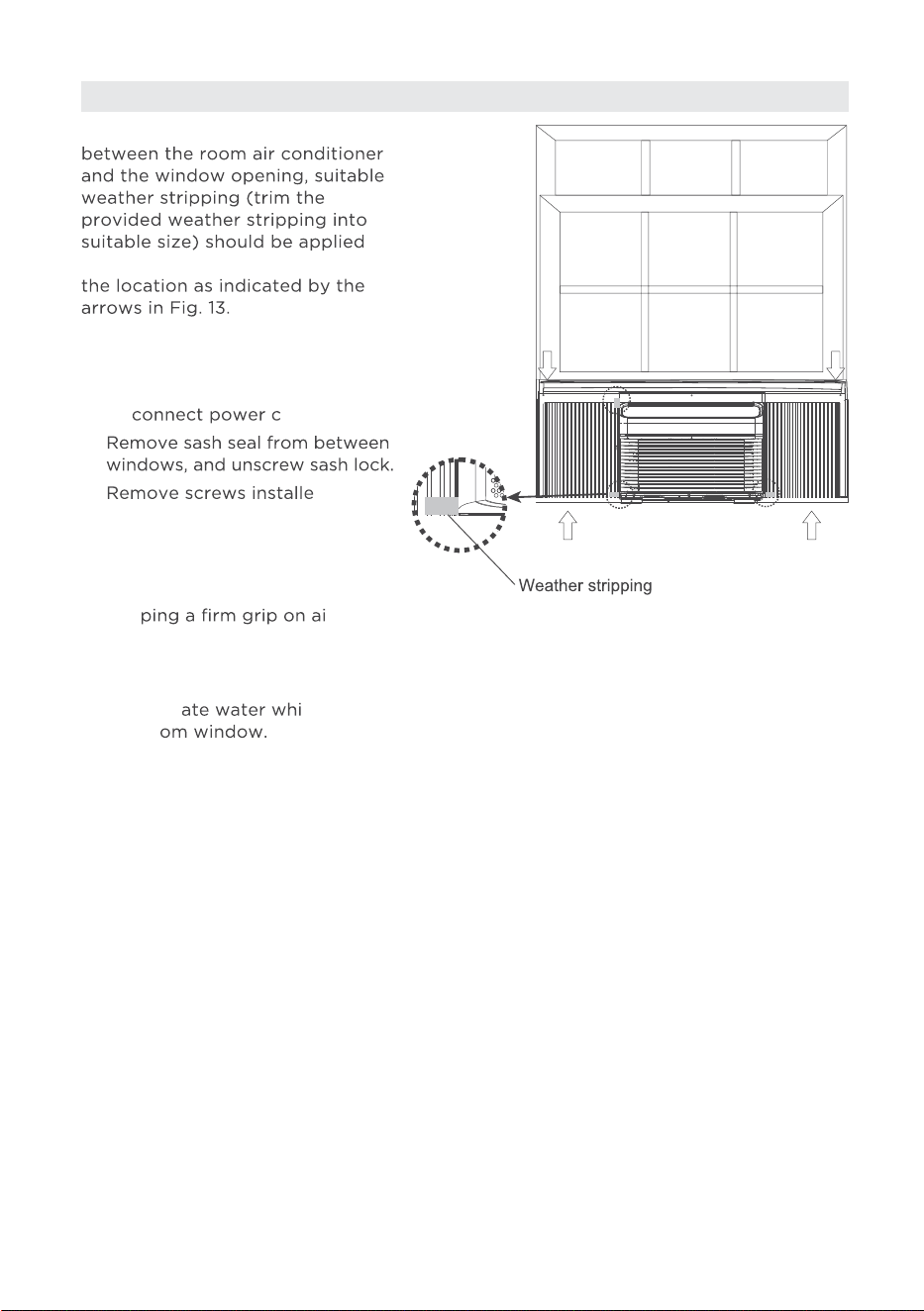
9. Suitable Weather Stripping
In order to minimize air/light leaks
in case of any gaps found at
Removing the air conditioner from
Window
• Turn the air conditioner off, and
dis ord.
•
• d
through frame and framelock.
• Remove the insulation panel
and close (slide) side panels
into frame.
• Kee r
conditioner, raise sash and
carefully remove.
• Be careful not to spill any
condens
le lifting
unit fr Store parts
WITH air conditioner.
Fig. 13
21
OPERATING INSTRUCTIONS
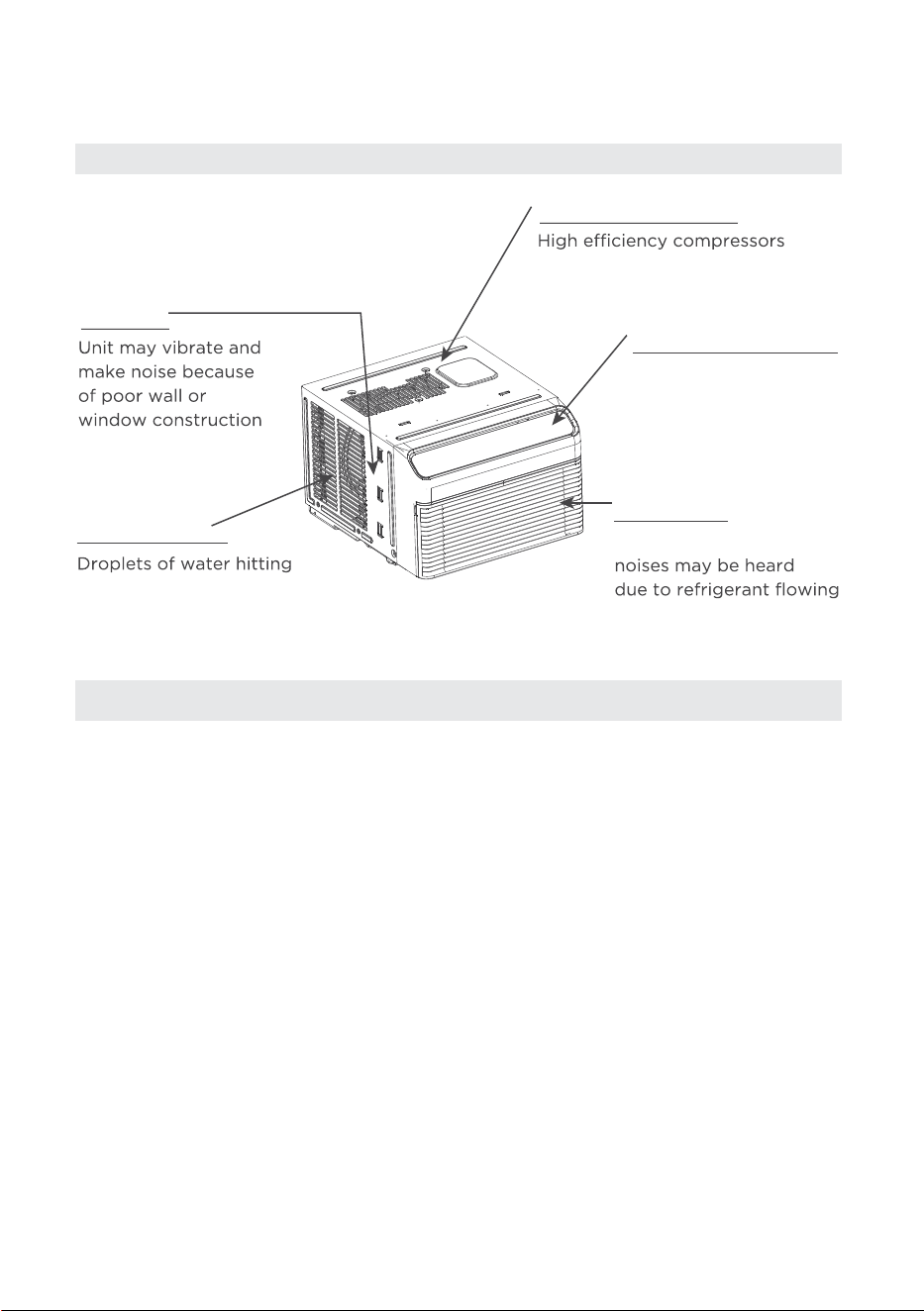
Normal Operating Sounds
NOTICE
All the illustrations in this manual are for explanation purpose only. The actual
installation may vary.
Sound of Rushing Air
High Pitched Chatter
Vibration
Trickling Sound
Gurgle/Hiss
or incorrect installation.
may have a high pitched
sound during cooling cycle.
In front of the unit, the
sound of air being
moved by the fan may
be audible.
Gurgling or hissing
through evaporator
during normal operation.
condenser during normal
operation may cause a
trickling sound.
22
NOTICE
Always wait 3 minutes when turning the unit off and then on again, or when changing from
cool to fan and back to cool. This prevents damage from occurring to the compressor.
Air Conditioner Features
WARNING
To reduce the risk of fire, electrical shock, or injury to people or property, read the
SAFETY PRECAUTIONS before operating this appliance.
To begin operating the air conditioner, follow these steps:
3. Set the thermostat to the coldest temperature setting.
4. Select the Cool mode setting.
Cooling Operation
NOTICE
• The relative humidity of the room should be less than 80%. If the unit is used in a
condition with a relative humidity over 80%, there will be condensed water on the
surface of the unit.
• Performance may be reduced outside of these operating temperatures.
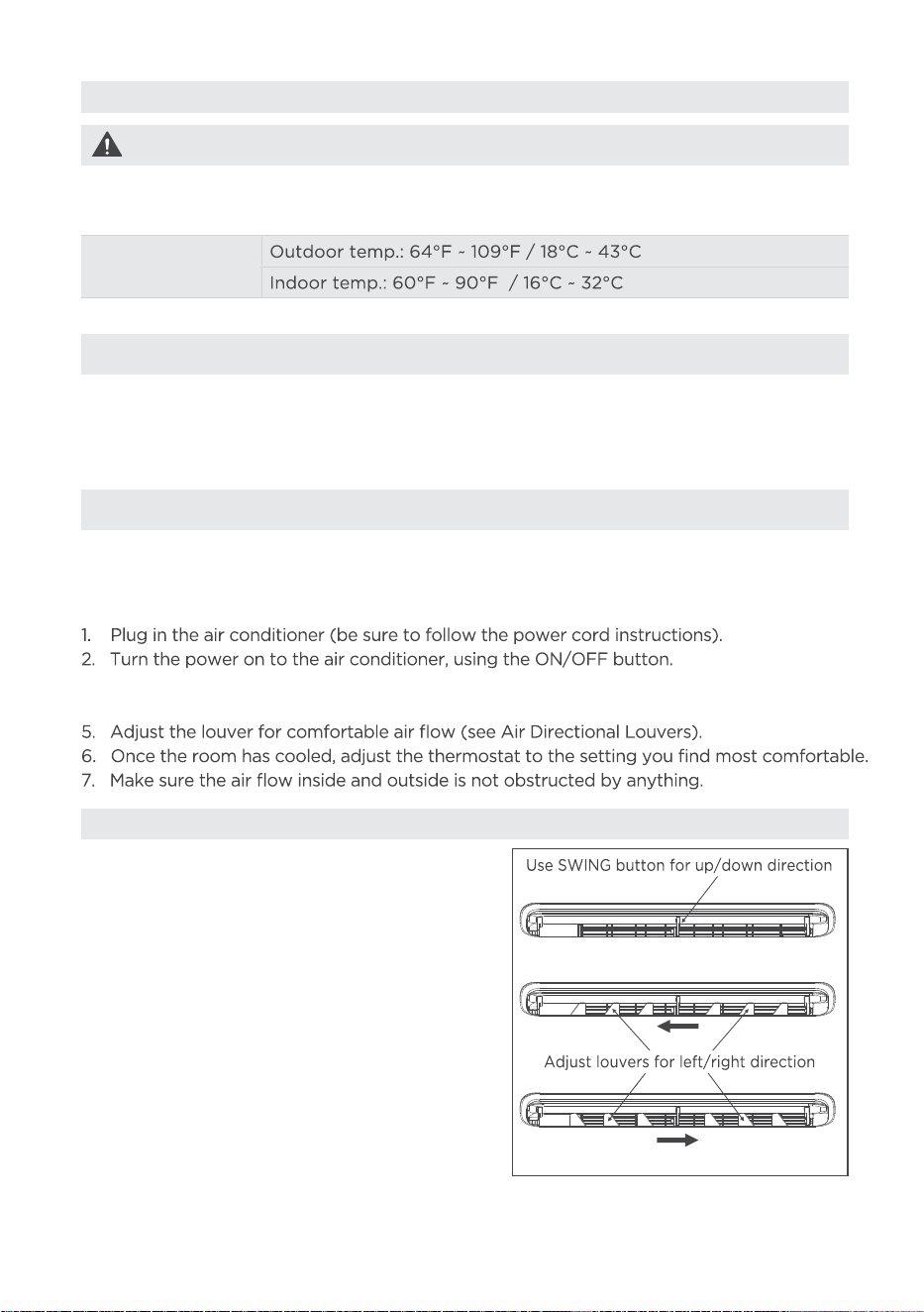
Air Directional Louvers
The louvers allow for adjustment of airflow
both vertically (up or down) and horizontally
(left or right) throughout the room. To adjust
the up/down direction, use the SWING button
until the desired position is reached. For
left/right adjustment, manually move the
louvers to the desired direction.
Air Direction
23
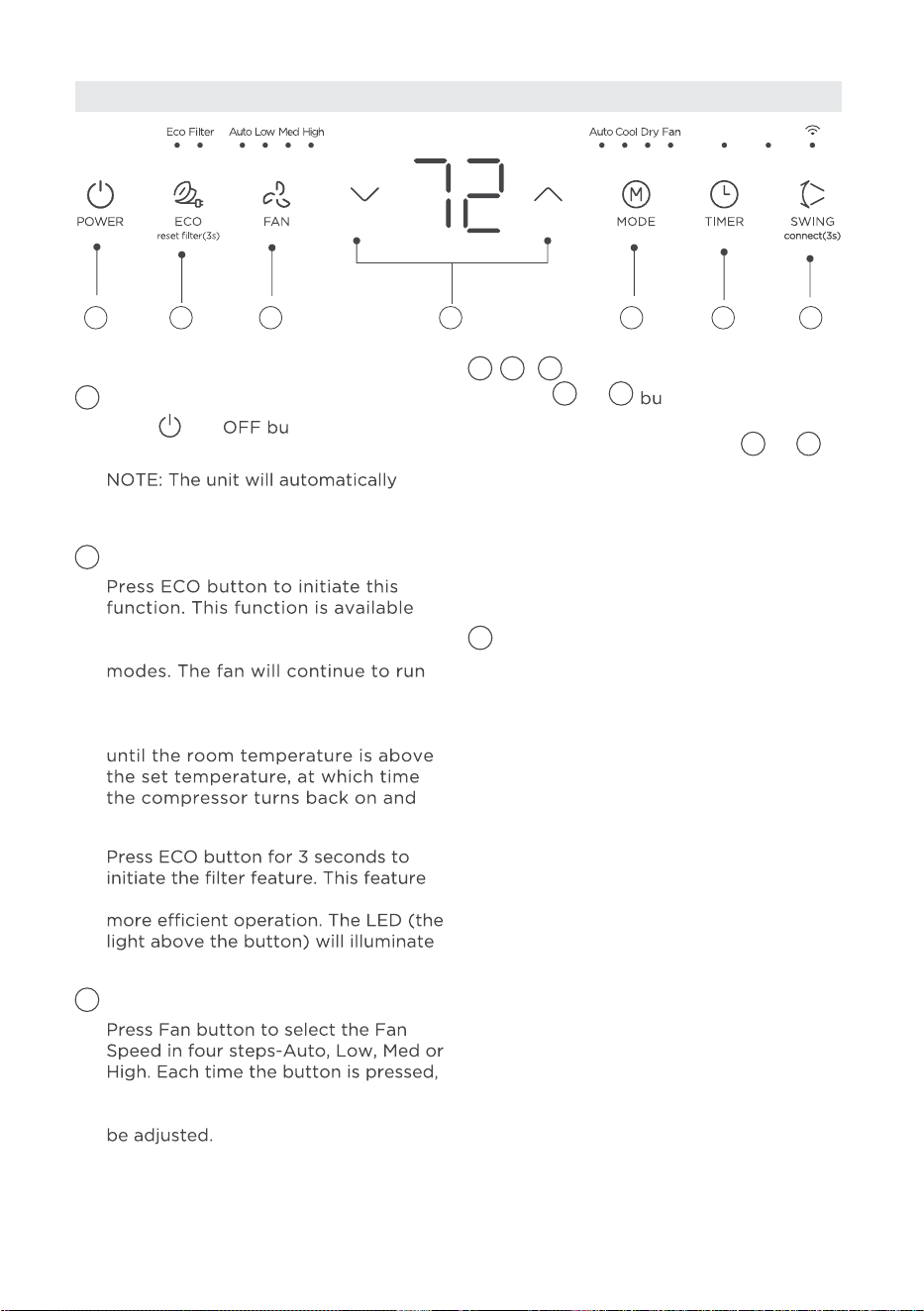
Operation buttons
Press ON/
tton to turn unit
on or off.
initiate the Energy Saver function
under cool, Dry, and Auto modes.
ECO button
on COOL, DRY, and AUTO (only
AUTO-COOLING and AUTO-FAN)
for 3 minutes after the compressor
shuts off. The fan then cycles on
for 2 minutes at 10 minute intervals
Cooling Starts.
is a reminder to clean the Air Filter for
after 250 hours of operation.
FAN button
the fan speed mode is shifted. For
some models, the fan speed can not
<
<
buttons
Press or
tton to change
<
<
temperature setting.
NOTE: Press or hold either or
<
<
MODE button
To choose operating mode, press the
MODE button. Each time you press
the button, a mode is selected in a
sequence that goes from, Auto, Cool,
Dry and Fan. The indicator light beside
the button will be illuminated and will
remain on once that mode is selected.
The unit will automatically initiate the
Energy Saver function under Cool, Dry,
and Auto (only Auto-Cooling and
Auto-Fan) modes.
1. To operate on Auto feature:
•
The air conditioner will automatically
regulate the room temperature to
maintain the selected setting.
• In this mode, the fan speed cannot
be adjusted, it starts automatically
at a speed according to the room
temperature.
1
3
5
2
4
• When the air conditioner is set to
Auto mode, it will automatically
choose either cooling or fan-only
operation based on the selected
temperature and the current room
temperature.
POWER button
ELECTRONIC CONTROL OPERATING INSTRUCTIONS
1 2 53 4 6 7
button until the desired temperature is
shown on the display. This temperature
will be automatically maintained
anywhere between 60°F (16°C) and
86°F (30°C). For the display to show
the actual room temperature, refer to
the "To Operate on Fan Only" section.

24
TIMER button
•
SWING button
Used to initiate the Auto swing
feature. When the operation is ON,
pressing the SWING button can stop
the louver at the desired angle.
Wireless operation (on some models):
•
For the first time to use Wifi
function, press the SWING button
for 3 seconds to initiate the Wifi
connection mode. The LED DISPLAY
shows ‘AP’ to indicate you can
set Wifi connection. If connection
(router) is successful within 8
minutes, the unit will exit Wifi
connection mode automatically and
the Wireless indicator illuminates.
If connection is failure within
8 minutes, the unit exits Wifi
connection mode automatically.
After a successful Wi-Fi connection,
press and hold the POWER and
DOWN buttons simultaneously for
3 seconds to disable the Wi-Fi
function. The LED display will show
"OF" for 3 seconds. To enable the
Wi-Fi function again, press and hold
the POWER and UP buttons
simultaneously, and the LED display
will show "On" for 3 seconds.
6
7
2. To operate on COOL mode:
• Choose Cool Mode to set the
cooling function. Use the Up and
Down buttons to choose the
desired temperature. When Cool
Mode is selected, the fan speed
can be adjusted by pressing the
fan button.
3. To operate on Dry mode:
•
In this mode, the air conditioner will
generally operate as a dehumidifier.
Since the conditioned space is
a closed or sealed area, some
degree of cooling will continue.
On Dry mode, the fan speed is not
adjustable.
4. To operate on Fan Only:
•
Use this function only when
cooling is not desired, such as for
room air circulation or to exhaust
stale air (on some models).
(Remember to open the vent
during this function, but keep it
closed during cooling for maximum
cooling efficiency.)
• In Fan only mode, the temperature
is not adjusted.
•
Press or hold the or button
to change the Auto time by 0.5
hour increments, up to 10 hours,
then at 1 hour increments up to 24
hours. The control will count down
the time remaining until start.
<
<
•
• Turning the unit ON or OFF at any
time or adjusting the timer setting
to 0.0 will cancel the Auto Start/
Stop timed program.
The selected time will register
in 5 seconds, and the system
will automatically revert back to
display the previous temperature
setting or room temperature when
the unit is on. When the unit is off,
there is no display.
Press Timer button, the TIMER
indicator light illuminates. lt
indicates the Auto Start or Auto
Stop program is initiated. For
some units, continuing to press the
Timer button will cancel the timer
settings.
25
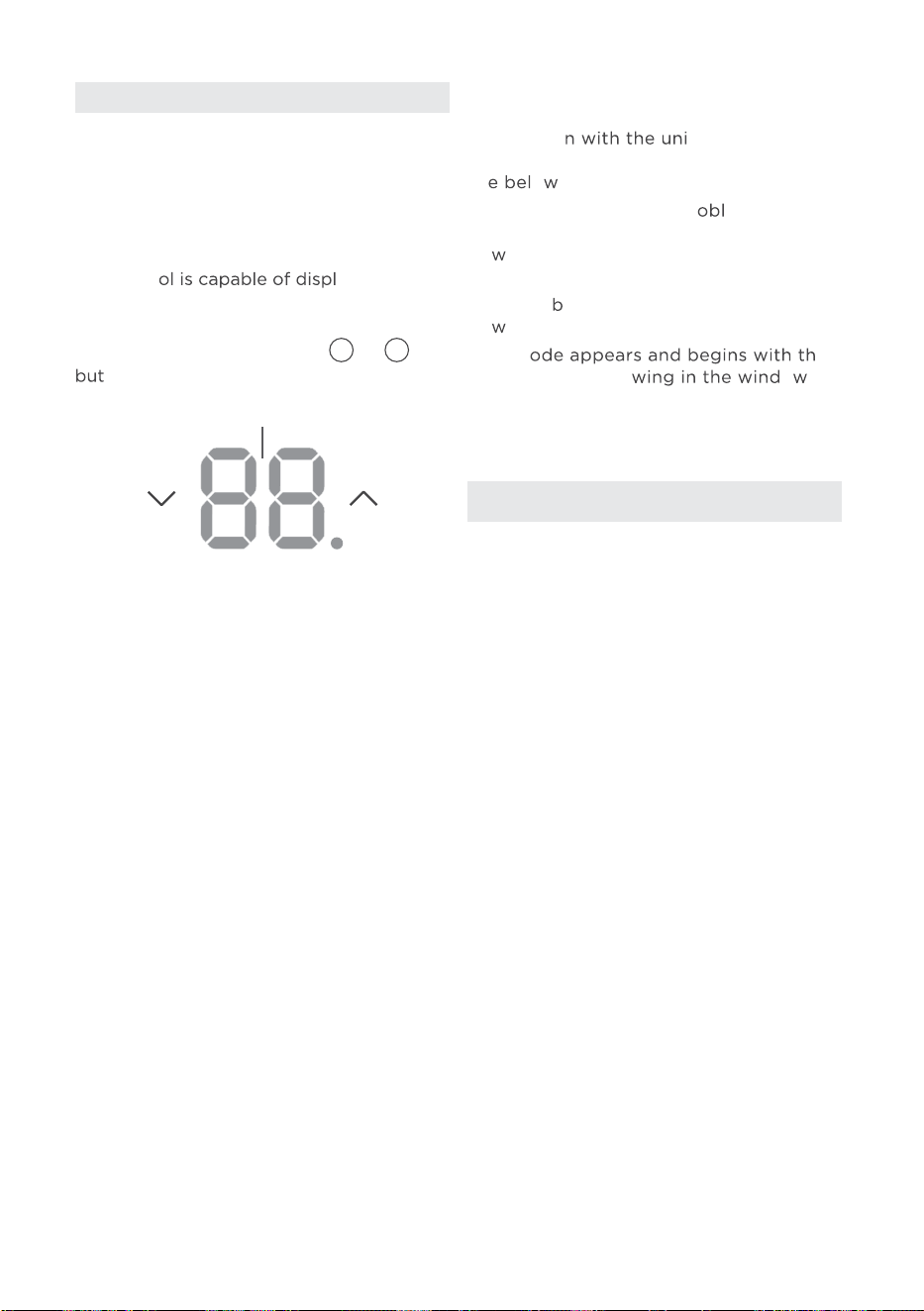
LED Display:
The contr
aying
temperature in degrees Fahrenheit or
degrees Celsius. To convert from one to
the other, press and hold the
<
or
<
tons at the same time for 3 seconds.
Display
DISPLAYS
Error codes:
The unit may stop operation due to a
malfunctio
t. If this occurs,
an error code may appear on the display
lik o .
Wait 10 minutes as the pr em may
resolve itself. If not, disconnect the
po er, then connect it again. Turn the
unit on.
If the pro lem persists, disconnect the
po er and contact customer service.
Error c e
letters as the follo o
display of indoor unit:
EH(xx), EL(xx), EC(xx) , PH(xx), PL(xx),
PC(xx).
NOTICE
If the unit turns off unexpectedly due to
the power being cut, it will automatically
restart with the previous function setting
when the power resumes.
Shows the set temperature in “°C” or
“°F” and the Auto-timer settings. While
on Fan Only mode, it shows the room
temperature. If the room temperature is
too high or low, it will display “ HI” or “ LO”.
26
CLEANING AND MAINTENANCE
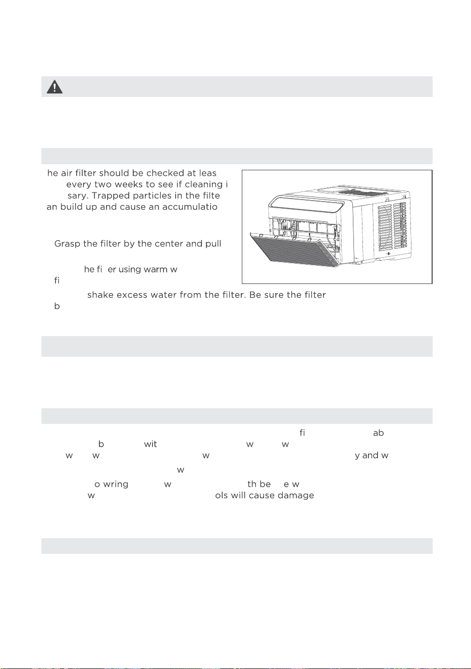
Air Filter Cleaning
Cabinet Cleaning
Winter Storage
T t
once s
neces r
c n
of frost on the cooling coils and reduce
performance.
•
up and out.
• Wash t lt ater. Rinse
lter thoroughly.
• Be sure to unplug the air conditioner to prevent shock or
re hazard. The c inet and
front may e dusted h an oil-free cloth or ashed ith a cloth dampened in a solution
of arm ater and mild liquid dish ashing detergent. Rinse thoroughl ipe dry.
• Never use harsh cleansers,
ax, or polish on the air conditioner.
• Be sure t excess ater from the clo for iping around the controls.
Excess ater in or around the contr to the air conditioner.
• Plug in air conditioner.
CAUTION
Clean the air conditioner occasionally to keep it looking new. Be sure to unplug the
unit before cleaning to prevent shock or fire hazards.
NOTICE
Never use hot water over 104°F (40°C) to clean the air filter. Never attempt to
operate the unit without the air filter.
If the air conditioner will be stored during the winter, carefully remove it from the window
following the installation instructions. Take care not to spill any standing water from the
unit’s base pan. If water is present, drain it carefully. Once drained, cover the unit with
plastic or return it to the original carton for storage.
• G
The filter can be vacuumed instead.
ently
is thoroughly dry
efore replacing.
•
27
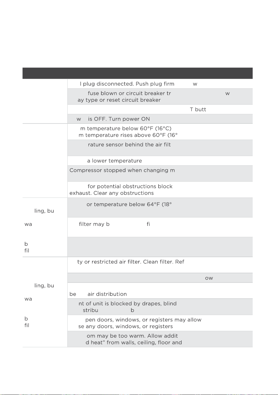
TROUBLESHOOTING TIPS
Before requesting service, review this list, as it may help save time and reduce costs.
This list includes common occurrences that are not the result of defective workmanship
or materials in this unit.
Problem Solution
Air conditioner
does not start.
Wal
ly into all outlet.
House
ipped. Replace fuse ith time
del .
Plug Current Device Tripped. Press the RESE
on.
Po
er .
Air from unit
does not feel
cold enough.
Roo
. Cooling may not occur until
roo C).
Tempe
er is touching the cold coil.
Try to move it so it does not contact the cold coil.
Set to
.
odes. Wait 3 minutes after
set to the COOL mode.
Check
ing the outdoor intake/
.
Air conditioner
coo
t
room is too
rm- ice
forming on
cooling coil
ehind air
ter.
Outdo
C). To defrost the coil, set to
FAN ONLY mode.
Air
e dirty. Clean lter. Refer to Care and Cleaning
section. To defrost, set to FAN ONLY mode.
Thermostat set too cold for night-time cooling. To defrost the coil,
set to FAN ONLY mode. Then, set temperature to a higher setting.
Air conditioner
coo
t
room is too
rm- NO ice
forming on
cooling coil
ehind air
ter.
Dir
er to Care and Cleaning
section.
Temperature is set too high, set temperature to a l
er setting.
Air directional louvers positioned improperly. Position l
ouvers for
tter .
Fro
s, furniture, etc. - restricts
air di tion. Clear o struction in front of unit.
Any o
cold air to escape.
Clo .
The ro ional time to remove
“store furniture.
28
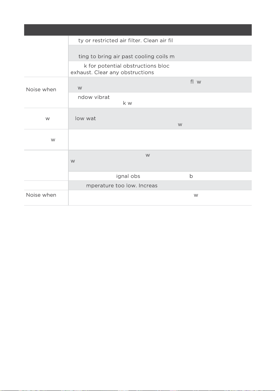
Problem Solution
Air conditioner
turns on and
off rapidly.
Dir ter.
Outside temperature extremely hot. Set FAN speed to a higher
set
ore frequently.
Chec
king the outdoor intake/
.
unit is cooling.
Air movement sound. It is normal to hear the air o . If too loud, set to a
slo
er FAN setting.
Wi ion - poor installation. Refer to installation
instructions or chec ith installer.
Water dripping
INSIDE
hen
unit is cooling.
Improper installation. Tilt air conditioner slightly to the outside to
al er drainage.
Refer to installation instructions - check ith installer.
Water dripping
OUTSIDE
hen
unit is cooling.
Unit removing large quantity of moisture from humid room. This is
normal during excessively humid days.
Remote sensing
deactivating
prematurely
(some models).
Remote control not located
ithin range. Place remote control
ithin 26 feet (8 m) and pointed in the general direction of the air
conditioner unit.
Remote control s
tructed. Remove o struction.
Room too cold. Set te
e set temperature.
unit starts.
A “da-da” sound may occur for thirty seconds hen the unit is
turned on due to the compressor starting. It is normal.
29
REMOTE CONTROL AND APP INSTRUCTIONS
26.2 ft (8 meters)
C-SENS
E
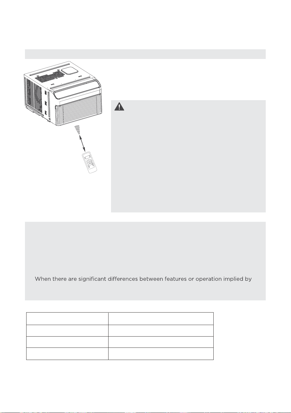
Location of the remote control
Use the remote controller within a distance of 26.2 ft
(8 meters) from the air conditioner, pointing it towards
the receiver. Reception is confirmed by a beep.
Handling the Remote Control
•
The air conditioner will not operate if curtains,
doors or other materials block the signals from the
remote control to the unit.
•
Prevent any liquid from spilling onto the remote
control. Do not expose the remote control to
direct sunlight or heat.
•
If the infrared signal receiver on the indoor unit is
exposed to direct sunlight, the air conditioner may
not function properly. Use curtains to prevent the
sunlight from falling on the receiver.
•
If other electrical appliances react to the remote
control, either move these appliances or consult
your local dealer.
CAUTION
NOTICE
•
Button design is based on typical model and may vary slightly from the actual one
you purchased.
•
All the functions described are accomplished by the unit. If the unit is without a
feature, the unit will not respond if the corresponding button on the remote is
pressed.
•
remote control illustration and the actual functions described in the USER’S MANUAL,
the descriptions in the USER’S MANUAL shall prevail.
the
Model
Rated Voltage
8m
3.0V( Dry batteries R03/LR03×2)
Environment
Signal Receiving Range
-5°C~60°C(23°F~140°F)
RG51F2(2)/CEFU1
30
TEMP :
Model: RG51F5(2)/CEU1
SHORT CUT
1
3
5
7
11
2
4
6
8
10
13
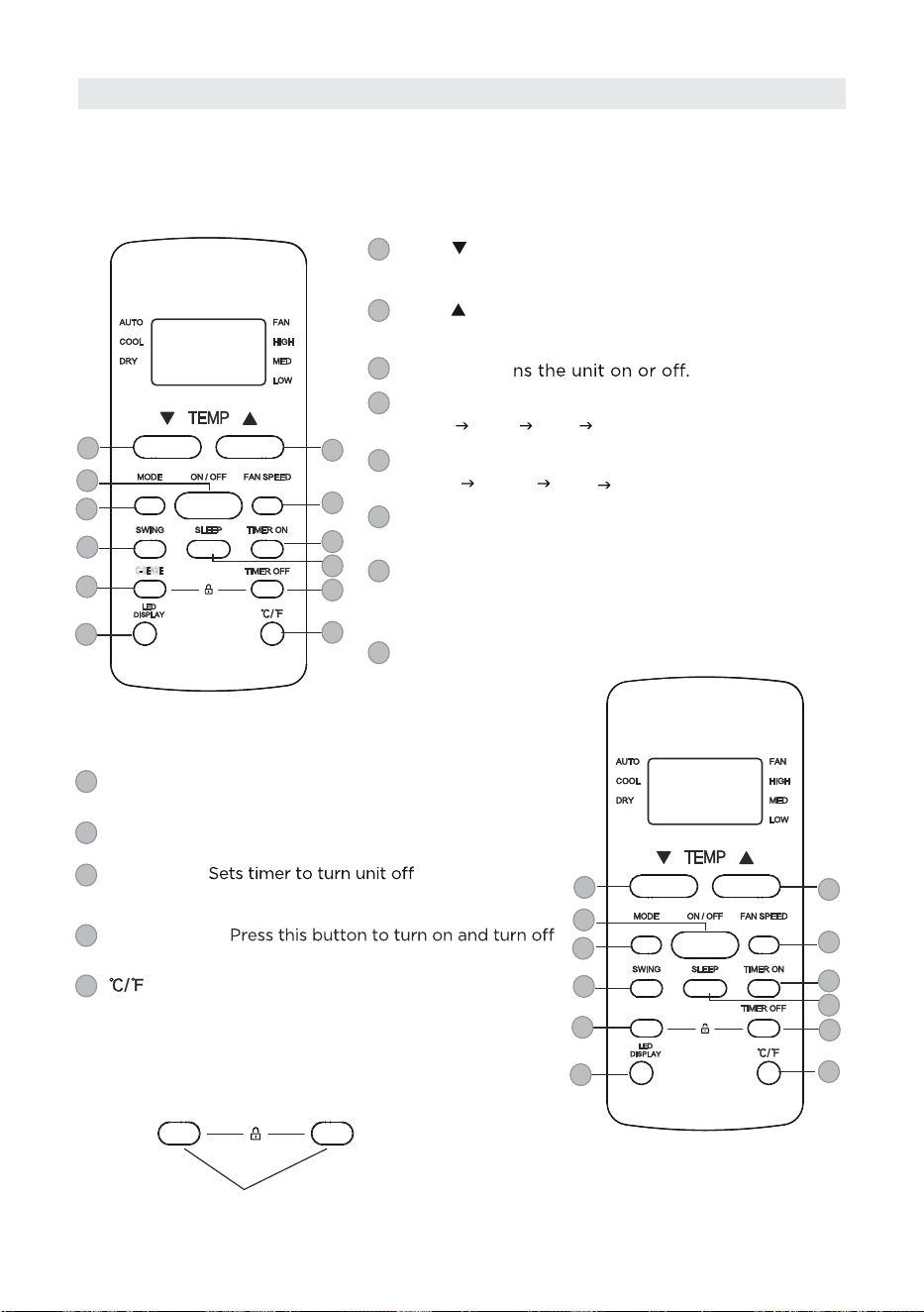
Before using the new air conditioner, take time to familiarize yourself with the remote
control. The following is a brief introduction to the remote control. For detailed
instructions on how to operate the air conditioner, refer to the "How to Use Basic
Functions" section of this manual.
1
3
5
7
9
2
4
6
8
13
11
12
Model: RG51F2(2)/CEFU1
ON/OFF: Tur
MODE: Scrolls through operation modes as follows:
SWING: Starts and stops the horizontal louver
movement. Hold down for 2 seconds to initiate
vertical louver auto swing feature(some units) .
AUTO
COOL DRY
FAN
FAN SPEED: Selects fan speeds in the following order:
AUTO
LOW
MED HIGH
TIMER ON: Sets timer to turn unit on (see How to
Use Basic Functions for instructions).
3
5
7
4
6
TIMER OFF: (see How to Use
Basic Functions for instructions).
9
SLEEP: Saves energy during sleeping hours .
8
11
COMFORT SENSE: Temperature sensing and room
temperature display button.
TEMP :
Decreases temperate in 1°C/1°F increments.
Min. temperature is 16°C/60°F.
1
Increases temperate in 1°C/1°F increments.
Max. temperature is 30°C/86°F.
2
LED DISPLAY:
the display on the indoor unit.
: Press this button to alternate the temperature
display between the °C & °F.
NOTE: Press together the two buttons simultaneously
for 5 seconds to lock the keyboard. Press together the
two buttons for 2 seconds to unlock the keyboard.
Press together simultaneously
12
13
12
SHORT CUT: Sets and activates your favorite pre-settings.
10
Buttons and Functions
C-SENSE
31
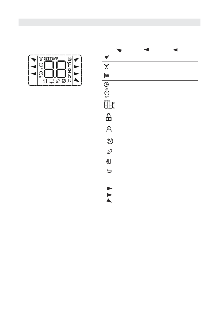
Information are displayed when the remote controller is power up.
Note:
All indicators shown in the figure are for the
purpose of clear presentation. But during the
actaul operation, only the relative function signs
are shown on the display window.
Displayed when data transmitted.
Displayed when remote controller is ON.
Low speed
NO display
Medium speed(some units)
High speed
Auto fan speed
Displayed when TIMER ON time is set
Displayed when TIMER OFF time is set
Indicated all the current settings are
locked
Shows set temperature or room
temperature, or time under TIMER setting
HIGH
MED
LOW
AUTO
COOL
FAN
DRY
Mode display
Fan speed indication
Displayed when Comfort Sense feature is
activated(some units)
Displayed when SLEEP feature is activated
AUTO
COOL
DRY
FAN
HIGH
MED
LOW
Horizontal louver swing display
Vertical louver auto swing display
Fresh feature display
Remote Screen Indicators
32
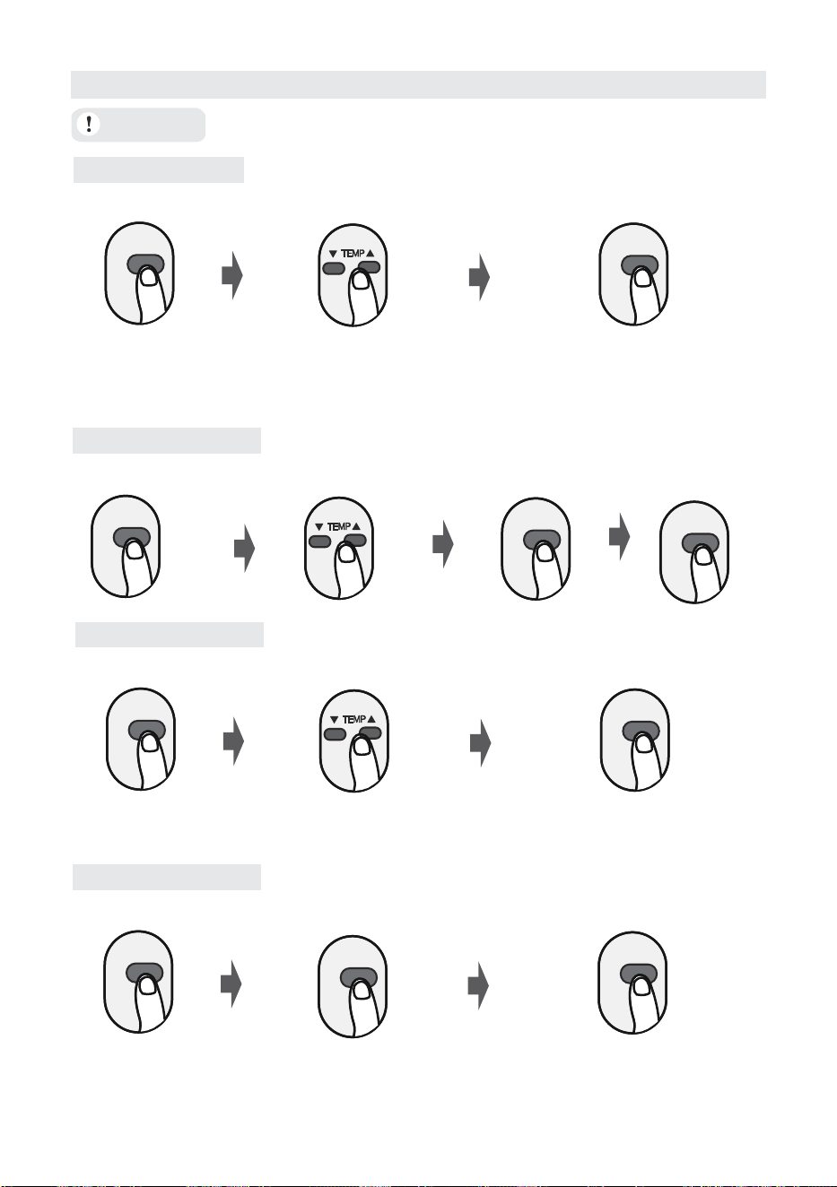
AUTO Mode
COOL Mode
DRY Mode
MODE
ON/OFF
MODE
FAN SPEED
ON/OFF
Select AUTO mode Set to desired temperature
NOTE:
1. In AUTO mode,
the unit will automatically select the COOL, or FAN function based on the
set temperature.
2. In AUTO mode, fan speed can not be set.
Turn on the air conditioner
MODE
ON/OFF
Select DRY mode Set the desired temperature Turn on the air conditioner
FAN Mode
MODE
ON/OFF
Select FAN mode Turn on the air conditioner
Select COOL mode Set the temperature Turn on the air
conditioner
Set the fan speed
FAN SPEED
Set the fan speed
NOTE: In DRY mode, fan speed can not be set since it has already been automatically
controlled.
NOTE: In FAN mode, the temperature cannot be set. As a result , no temperature
displays in remote screen.
Before operation, please ensure the unit is plugged in and power is available.
ATTENTION
How to Use Basic Functions
33
Setting the TIMER
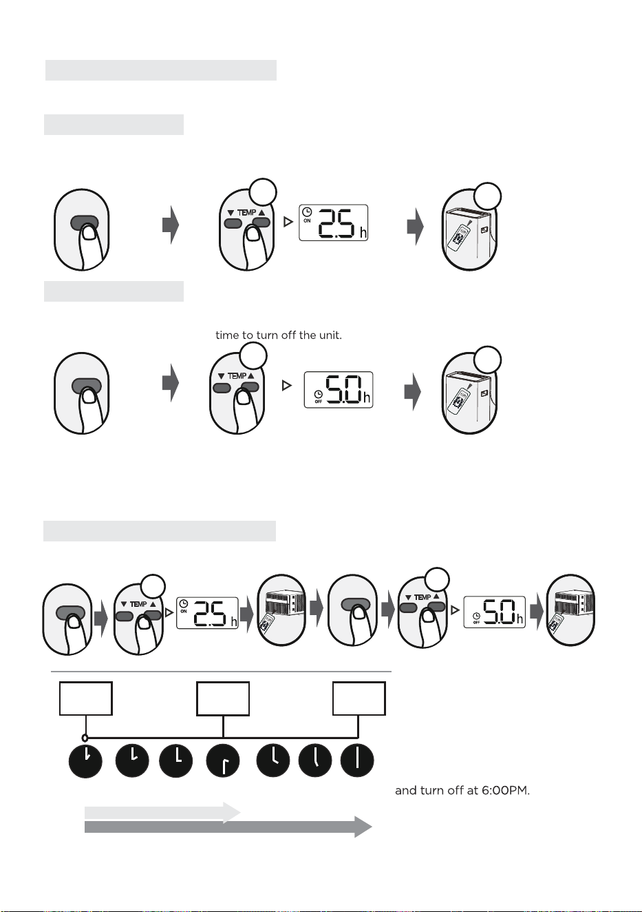
TIMER ON setting
TIMER OFF setting
TIMER ON & OFF setting(example)
TIMER ON/OFF - Set the amount of time after which the unit will automatically turn on/off.
Press TIMER ON button to
initiate the ON time sequence.
Press Temp. up or down button for
for multiple times to set the desired
time to turn on the unit.
Press Temp. up or down button for
for multiple times to set the desired
NOTE:
1. When setting the TIMER ON or TIMER OFF, the time will increase by 30 minutes increments with
each press, up to 10 hours. After 10 hours and up to 24, it will increase in 1 hour increments. (For
example, press 5 times to get 2.5h, and press 10 times to get 5h,) The timer will revert to 0.0 after 24.
2. Cancel either function by setting its timer to 0.0h.
Point remote to unit and wait 1sec,
the TIMER ON will be activated.
Press TIMER OFF button to
initiate the OFF time sequence.
Point remote to unit and wait 1sec,
the TIMER OFF will be activated.
Current
time 1PM
2:00PM 3:00PM
4PM 5PM
6PM
Timer starts
Unit turns
ON
Unit turns
OFF
2.5 hours later
5 hours later
3:30PM
Example: If current timer is 1:00PM,
to set the timer as above steps, the
unit will turn on 2.5h later (3:30PM)
x5
TIMER ON
TIMER ON
TIMER OFF
TIMER OFF
xn
xn
xn
Note that the time periods set for both functions are based on hours from the current time.
x10
My M
ode
F
o
llow M
e
L
ED
T
urbo
I
on
iser
Swing
Time
r
Se
lf
C
lea
n
Mod
e
On/
O
ff
F
an
Slee
p
AUTO
COOL
D
RY
HEAT
F
AN
HIGH
MED
LOW
SE
T
TE
MPE
R
AT
U
RE
1sec
My
M
o
de
F
ollow M
e
L
E
D T
urbo
Ioniser
Sw
ing
T
imer
Self
C
lean
Mode
On
/
Off
F
an
Slee
p
AU
TO
COOL
DRY
HE
AT
FAN
H
IGH
MED
LOW
SET TEMPERATURE
1sec
My
Mode
F
ollow
Me
LED
T
urbo
Ioniser
Swing
Timer
Se
l
f
Clean
Mod
e
O
n
/Off
F
a
n
Sleep
AUTO
COOL
DRY
HEAT
FAN
HIGH
MED
LOW
S
E
T TEMPERA
TU
R
E
My Mod
e
Follow
Me
LED
Tu
rbo
Ionise
r
Swing
Timer
Self Clean
Mod
e
On
/Off
F
a
n
Sle
e
p
AUTO
COOL
DRY
HEAT
FAN
HIGH
MED
LOW
SET TEMPER
AT
U
RE
34
If the memory feature is activated, “ ” displays for 3 seconds on the screen.
If the memory feature is stopped, “ ” displays for 3 seconds on the screen.
While the memory feature is activated, press the ON/OFF button, shift the mode or power
failure will not cancel the COMFORT SENSE function.
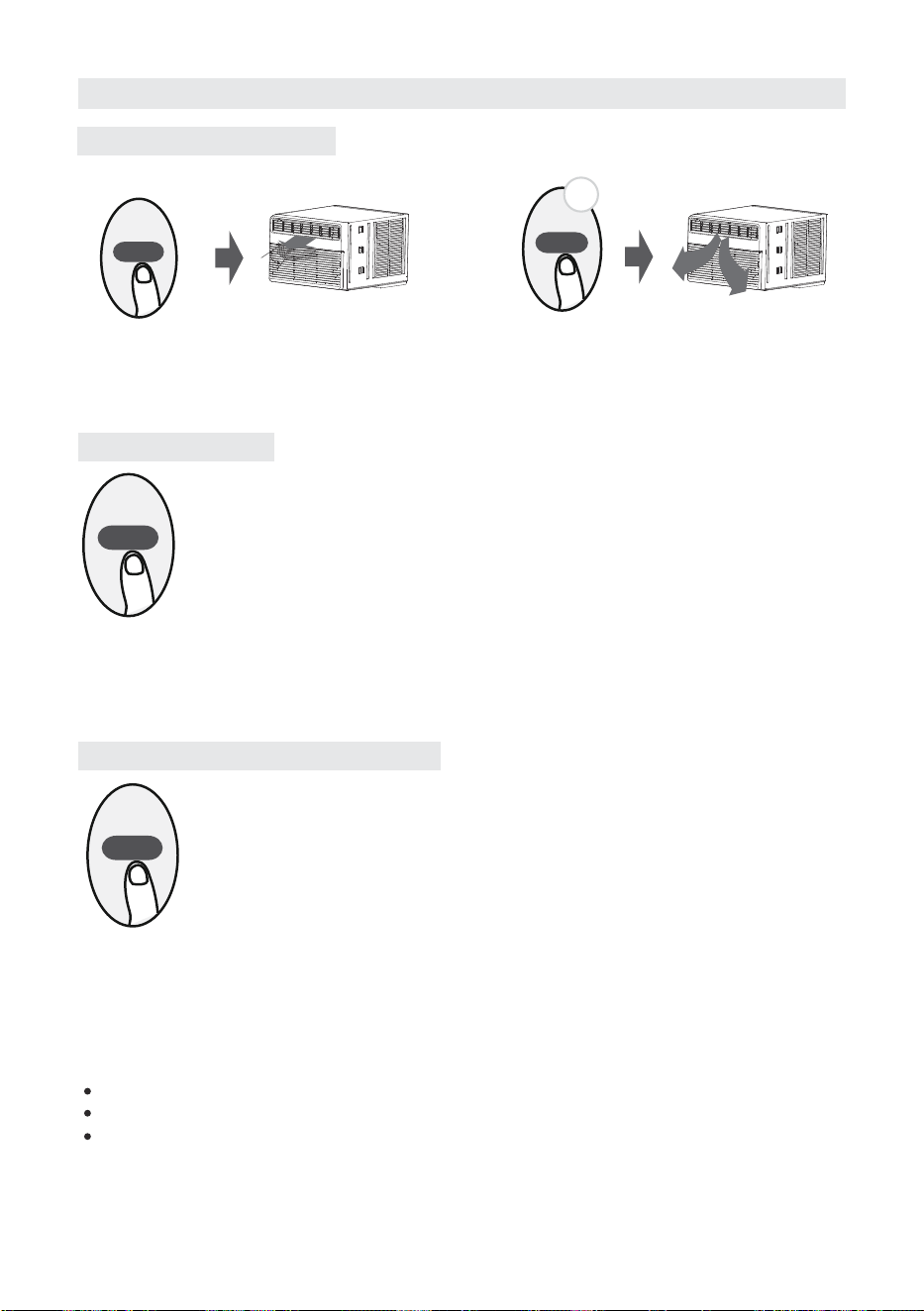
SWING
How to Use Advanced Functions
Swing function(some units)
COMFORT SENSE function(some units)
SLEEP function
Press Swing button
The horizontal louver will swing up and down
automatically when pressing Swing button.
Press again to make it stop.
Keep pressing this button more than 2 seconds,
the vertical louver swing function is activated.
(Model dependent)
SWING
2s
SLEEP
The SLEEP function is designed to reduce energy consumption during sleep, as it adjusts the
temperature settings to a more energy-efficient level while maintaining comfort. This function
can only be activated via remote control.
The sleep function is not available in Fan or Dry mode.Please refer to the OWNER’S MANUAL
for more details.
When the COMFORT SENSE function is activated, the remote display is actual temperature at its
location.
The remote control will send this signal to the air conditioner every 3 minutes interval until press
the COMFORT SENSE button again.
OF
NOTE: Press this button for seven seconds to start/stop memory feature of COMFORT SENSE
function.
On
C-SENSE
35
NOTES
• Button design is based on a typical model and may slightly vary from the actual
one you purchased.
• This device complies with part 15 of the FCC Rules. Operation is subject to the
following two conditions: (1) This device may not cause harmful interference,
and (2) this device must accept any interference received, including interference
that may cause undesired operation.
• This equipment has been tested and found to comply with the limits for a Class
B digital device, pursuant to part 15 of the FCC Rules. These limits are designed
to provide reasonable protection against harmful interference in a residen
tial
installation. This equipment generates, uses and can radiate radio frequency
energy and, if not installed and used in accordance with the instructions, may cause
harmful interference to radio communications. However, there is no guarantee that
interference will not occur in a particular installation. If this equipment does cause
harmful interference to radio or television reception, which can be determined by
interference by one or more of the following measures:
- Reorient or relocate the receiving antenna.
- Increase the separation between the equipment and receiver.
receiver is connected.
- Consult the dealer or an experienced radio/TV technician for help.
- Changes or modifications not approved by the party responsible for compliance
could void users authority to operate the equipment.
Battery Warning:
Do not mix old and new batteries and Do not mix alkaline, standard (carbon-zinc)
or rechargeable (ni-cad, ni-mh, etc.) batteries
Unique Identifier: Midea brand,RG51F2(2)/CEFU1
Responsible Party U.S. Contact Information
Midea America Corporation
300 Kimball Dr
Parsippany NJ
07054
This device complies with Part 15 of the FCC Rules. Operation is subject to the
following two conditions: (1) This device may not cause harmful interference, and
(2) this device must accept any interference received, including interference that
may cause undesired operation.
Telephone number or internet contact information: Midea.com/us
FCC Compliance Statement ( products subject to Part 15)
Supplier's Declaration of Conformity
47 CFR § 2.1077 Compliance Information
36
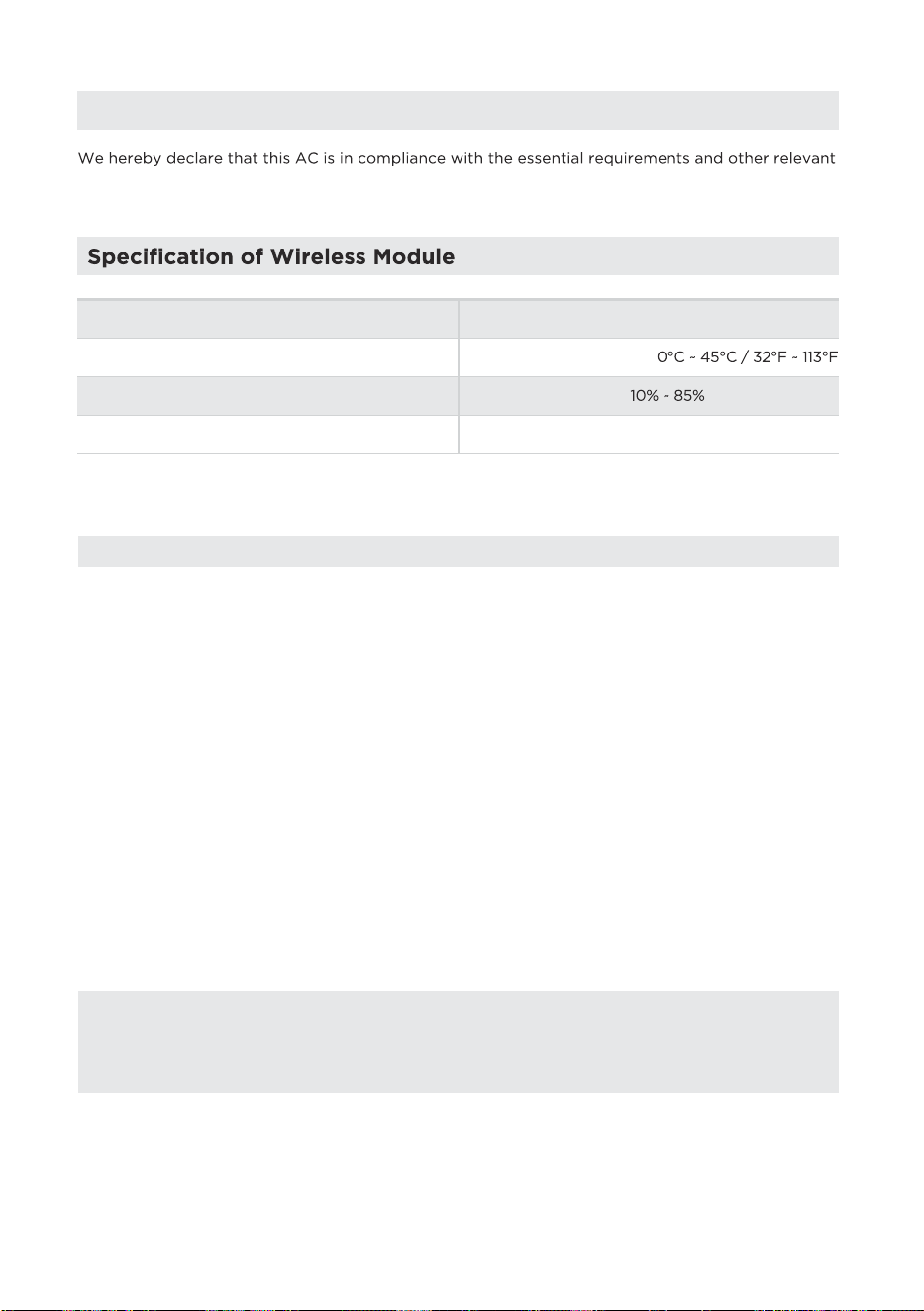
Declaration of Conformity
provisions of Directive 1999/5/EC.
Model: US-SK109 Dimensions: 41 x 24 x 5 (mm)
Operation Temperature:
Antenna Type: Printed PCB Antenna
Operation Humidity:
Frequency: WLAN 2400-2483.5 MHz
Power Input: DC 5V/500 mA
Maximum Transmitted Power: <20 dBm Max
1. Supports operating systems: Please refer to page 37.
2.
In the event of a OS update, there may be a delay between the update of the OS
and a related software update during which your OS may or may not be supported
until a new version is released. Your specific mobile phone or problems in your
network may prevent the system from working and Midea will not be responsible
for any problems that could be caused by incompatibility or network issues.
3.
This Smart AC only supports WPA-PSK/WPA2-PSK (recommended) encryption.
4.
To ensure proper scanning of the QR code, your smart phone must have at least a
5-megapixel camera.
5.
Due to unstable network connectivity, requests may time out. If this happens, rerun
the network configuration.
6.
Due to unstable network connectivity, commands may time out. If this happens,
the smartphone app and the actual product may display conflicting information.
The information displayed on the actual product is always the most accurate
available. Refresh the app to re-sync.
Midea will not be responsible for any problems that could be caused by
incompatibility or network issues, your wireless router and mobile phone.
NOTICE
PRECAUTIONS
37
1
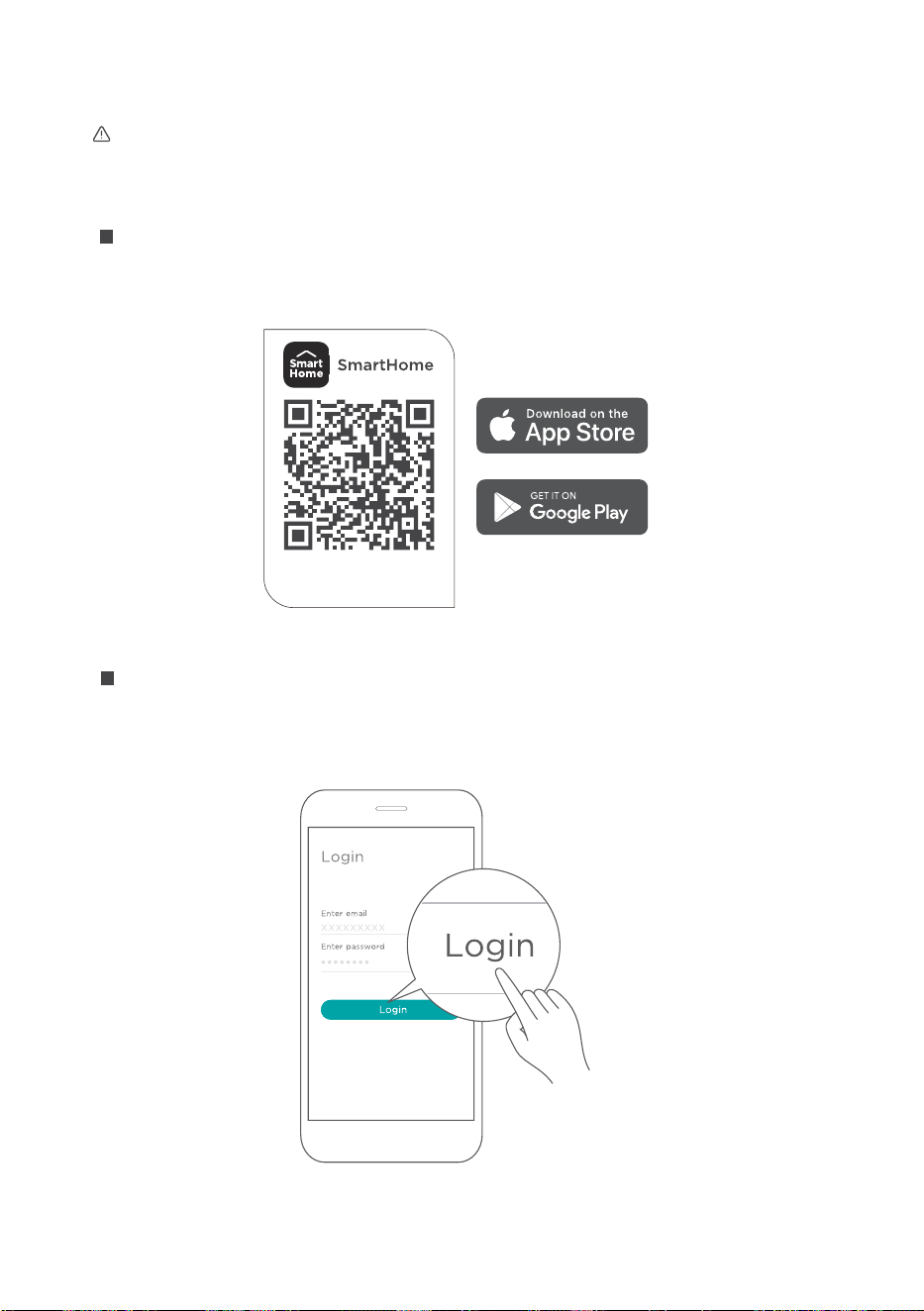
How to use SmartHome App
Ensure that the mobile phone is connected to the wireless network and that
Bluetooth is enabled.
The device must also be powered up.
Scan the QR code below to download the SmartHome app from app store or search
for it directly on the Google Play Store or Apple's App Store.
Step 1: Download the SmartHome app
Open the SmartHome app. If an existing SmartHome account is available, log in
directly; otherwise, create a new account. Alternatively, a third-party login platform
can also be used.
Step 2: Log in
Download the app
& activate product
38
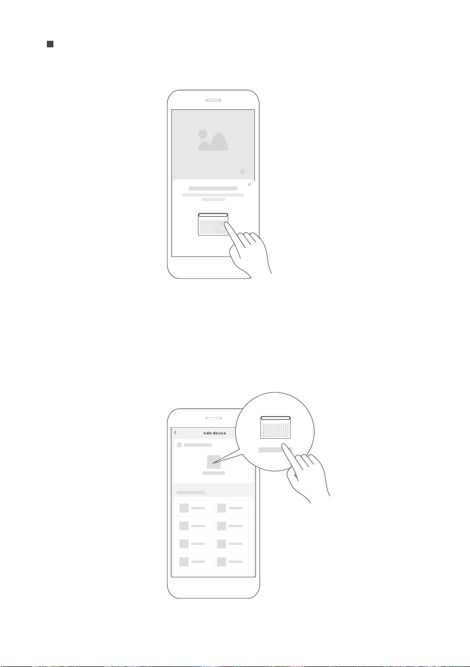
1) Upon logging in, a message may appear stating, "Smart devices discovered nearby."
Tap to add the device.
2) If the message does not appear, follow these steps: Tap the "+" icon and select
the device from the list of nearby available devices. If the device is not listed, add it
manually by first selecting the appropriate device category, such as i.e. Window AC
Step 3: Connecting the device
39
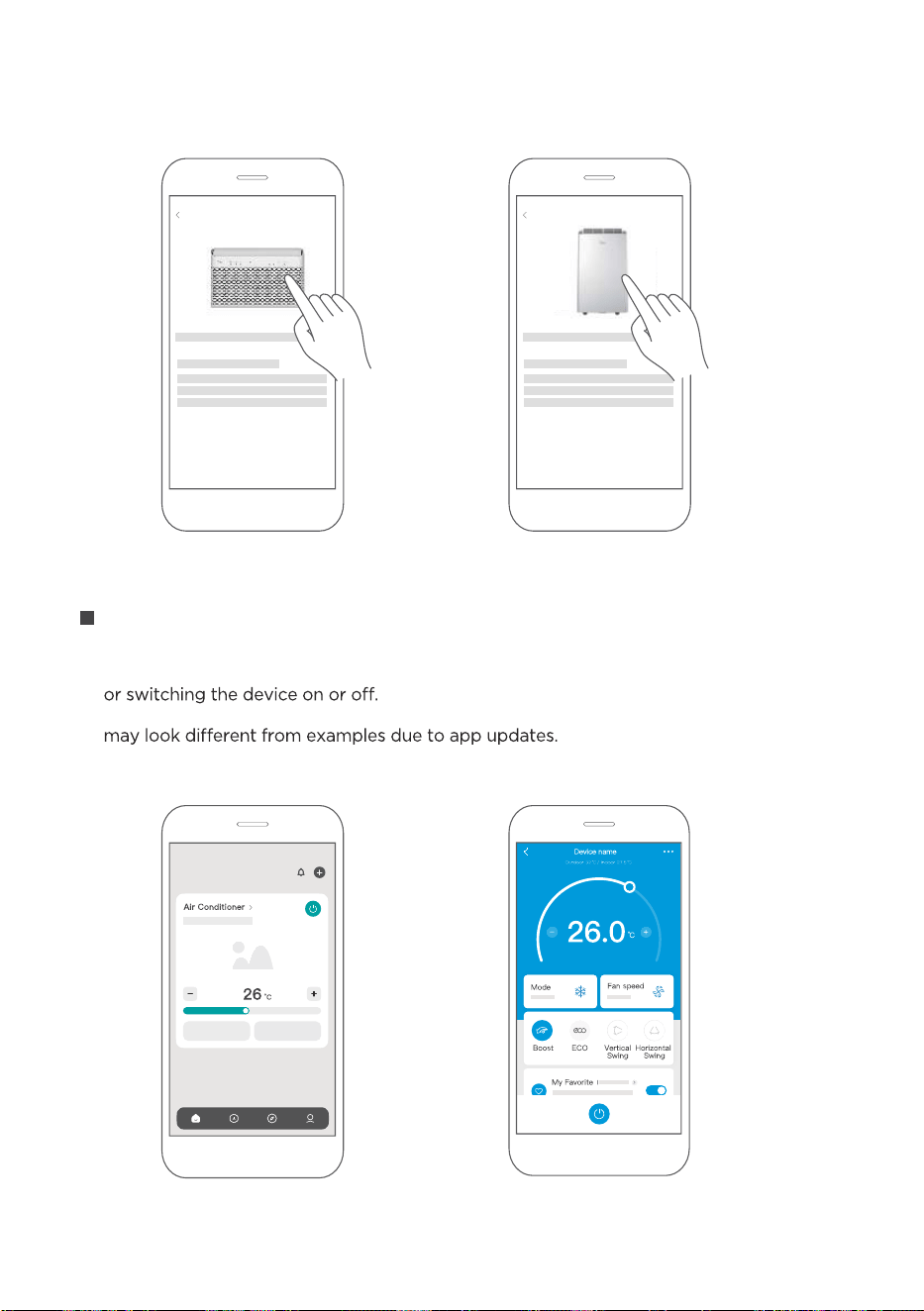
After pairing successfully, a card will be created for the device in the SmartHome app.
Shortcuts for basic functions will appear on the card such as changing the temperature
Tapping on the card, will reveal additional features and settings. The actual UI design
Step 4: Controlling the device
SmartHome
3) Follow the steps in the app to connect the device to the wireless network. If the
connection fails, refer to the additional instructions provided in the app for
troubleshooting.
Add device
For Window AC For Portable
AC
Add device
40
2
How to use Matter
Connect the Air Conditioner through Matter
Make sure the mobile device is connected to the wireless router.
Wireless router should support and turn on IPv6. Please make sure the smartphone
connects to 2.4G but not 5G network.
Matter is a connectivity technology that unifies the smart home by allowing devices and
ecosystems (such as Alexa, Google Home and Apple Home) to speak the same language
thus creating exciting new features and use cases.
To use Matter, at least one Matter-enabled smart speaker from Amazon, Google, or Apple
is required, along with the respective app for each platform.
--If a Matter-enabled smart speaker is available, proceed to the "How to Use Matter"
instructions on the following pages.
--If a Matter-enabled smart speaker is not available, full functionality can still be accessed
through the SmartHome app. Refer to the "How to Use SmartHome App" section on
page 37.
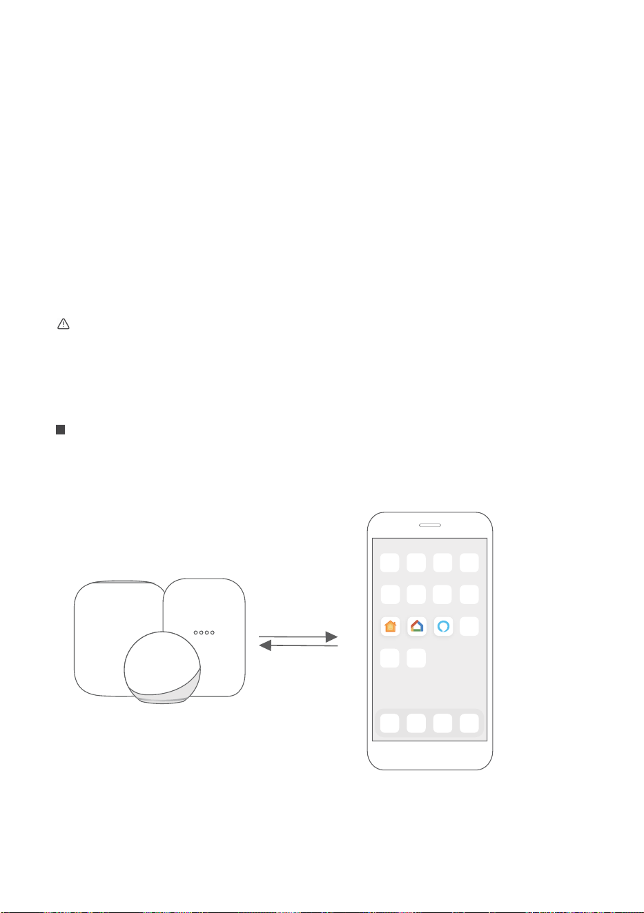
Step 1: Connect to smart speaker
Select a preferred ecosystem (Alexa, Google Home, or Apple Home) and ensure that
a Matter-enabled product, such as a smart speaker, is connected to the wireless router.
Apple Home Google Home Alexa
For best Matter compatibility, connect the AC to the Alexa, Google Home or Apple Home
ecosystems along with at least one of their respective Matter enabled smart speakers.
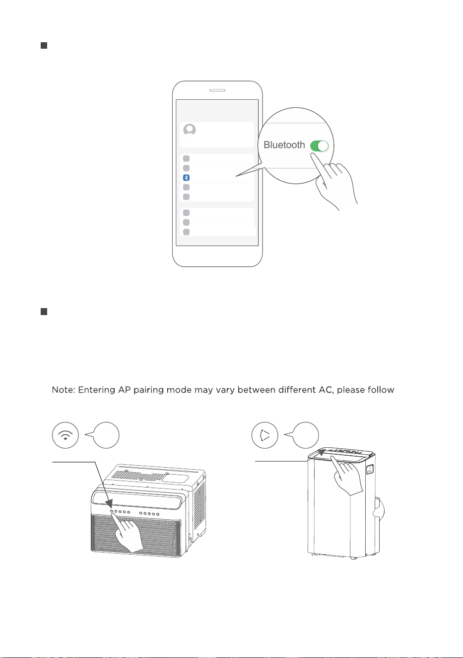
Turn on Bluetooth on the mobile device.
Step 2: Turn on Bluetooth
Settings
Bluetooth
Bluetooth
Window AC: Hold down the CONNECT / Power button for 3 seconds to begin the
pairing process (“AP” will appear on the AC’s display).
Portable AC: Hold down the SWING / Power button for 3 seconds to begin the pairing
process (“AP” will appear on the AC’s display).
instruction of AC panel.
Step 3: Enter AP mode
AP
CONNECT
AP
SWING
Window AC Portable AC
41
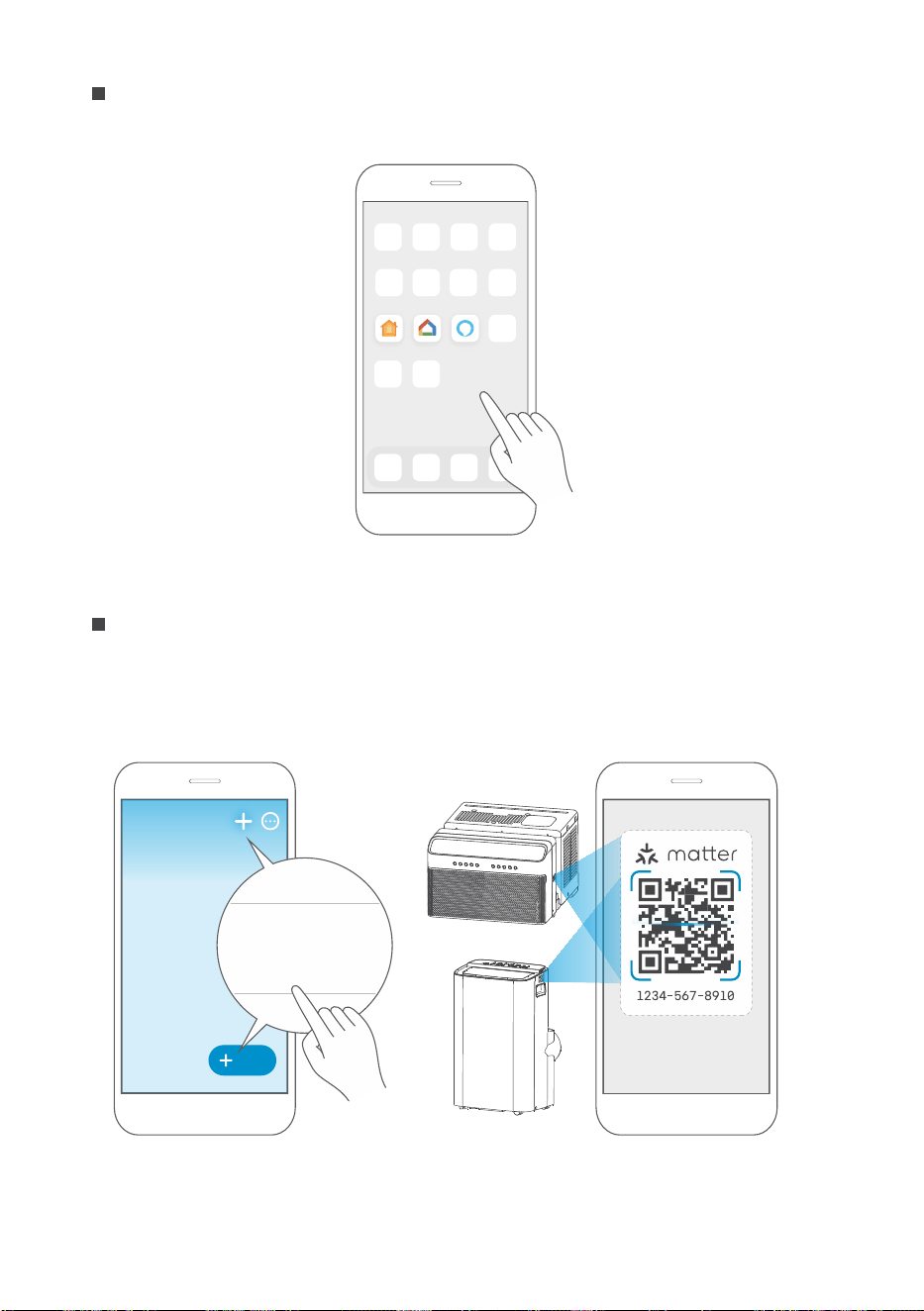
Open the Alexa, Google Home, Apple Home app on the mobile device.
Step 4: Open app
Apple Home Google Home Alexa
Tap the “+” and “Add Device/Accessory” or tap "+Add" in the app and then select
Matter device and scan the Matter QR code found on the side of the AC device.
Follow the respective instructions in the Alexa, Google Home or Apple Home app to
complete the pairing process.
Step 5: Scan matter QR code
Add
Add Device/Accessory
scan
Matter QR code
42
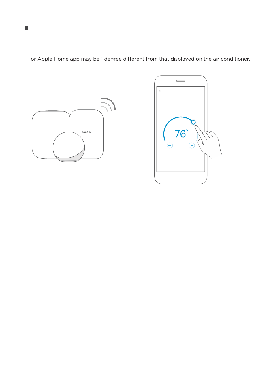
After pairing is successful, you can control your AC’s temperature and mode settings,
etc. through the respective ecosystem app and smart speaker.
Due to a compatibility issue, the temperature value shown in the Alexa, Google Home
However, this will not impact the device's ability to cool the room.
Step 6: Control device
Air conditioner
43
NOTE:
The functions shown in the Alexa, Google Home or Apple Home apps may change
with updates to their products or apps.
Setup processes and features may vary between ecosystems.
Make sure the Matter enabled app is up to date to ensure the best experience.
Periodically, the device's software will be updated to improve experience.
Device software updates can be accomplished through the SmartHome app.
is developed by the Connectivity Standards Alliance TM. This brand,
related logos, and marks are trademarks of the Alliance, all rights reserved.
Use of the Works with Apple badge means that an accessory has been designed to
work specifically with the technology identified in the badge and has been certified
by the developer to meet Apple’s performance standards.
Apple is not responsible for the operation of this device or its compliance with
safety and regulatory standards.
App & Smart Speakers can support Matter only when using these
versions or above.
9094439556
Google Play services min version: 22.36.15
Google Home app (GHA) min version: 2.58.24.1-dogfood
Google Hub firmware min version: 1.56.324896
(appears on hub as Chromecast firmware version)
2.2.536317
16.5
Device Version
iOS 16.5iPhone
Apple Home
Pod
Alexa Echo
Device
Android
Google
Home Hub
Alexa App
44
RSSs.
device, pursuant to part 15 of the FCC Rules. These limits are designed to provide
equipment generates, uses and can radiate radio frequency energy and, if not installed
particular installation. If this equipment does cause harmful interference to radio or
measures:
--Reorient or relocate the receiving antenna.
receiver is connected.
--Consult the dealer or an experienced radio/TV technician for help.
other relevant provisions of RE Directive 2014/53/EU. A copy of the full DoC is attached
(European Union products only).
radiation exposure limits set forth for an uncontrolled environment. In order to avoid the
(1) This device may not cause interference;and
(2) This device must accept any interference,including interference that may cause
undesired operation of the device.
Declaration of conformity
FCC ID: 2ADQOMDNA23
IC: 12575A-MDNA23
NOTE:
45
4
WARRANTY
Air Conditioner Limited Warranty
Warranty
• T
• The date of delivery establishes the warranty period, should service be required.
Year Full warranty from the date of delivery or the purchase date, whichever is later.
Midea, through its authorized servicers will:
• Pay all costs for reparing or replacing parts of this appliance
hich n materials or
rkmanship.
Consumer will be responsible for:
• Diagnostics, removal, transportation and reinstallation cost requ
cause of service.
• Costs of service calls that are a result of items listed under NORMAL RESPONSABILITIES OF THE CONSUMER**
Midea replacement parts sha
used an arranted only for the origina arranty.
NORMAL RESPONSABILITIES OF THE CONSUMER**
This warranty applies only to products in ordinary household use, and the consumer is responsible for the items
listed below:
1. Proper use of the appliance in acordance
h instructions provide h the product.
2. Routine maintenance and cleaning necessary to keep th
orking condition.
3. Proper installation
n authorized service professional in accordance ith instructions provided ith the appliance and
in accordanc
h ng, electrical and/or gas codes.
4.
5. Expenses for making the appliance a e for servicing.
6.
EXCLUSIONS
This warranty does not cover the following:
1) Failure cause
amage to the unit ile in your possesion (other than damage ca
malfunction
nstallation, or unreasona use of the unit, inc ation, failure to
provide reason
e and necessary maintenance or to follo h allation and Operating Instructions.
2)
3)
tness
for use or purpose.
4)
NOTICE: Some states do not allow the exclusions or limitation of incidental or consequential damages. So this
limitation or exclusion may not apply to you.
IF YOU NEED SERVICE
T ritte arranty gives you speci c legal rights. You may also have other rights that vary from state to state.
1) Contact Midea Consumer Services or an authorized Midea services at 1 866 646 4332.
2)
6


CW009UI-QB
20241112
2024
16120300A34452