Aug. 2022
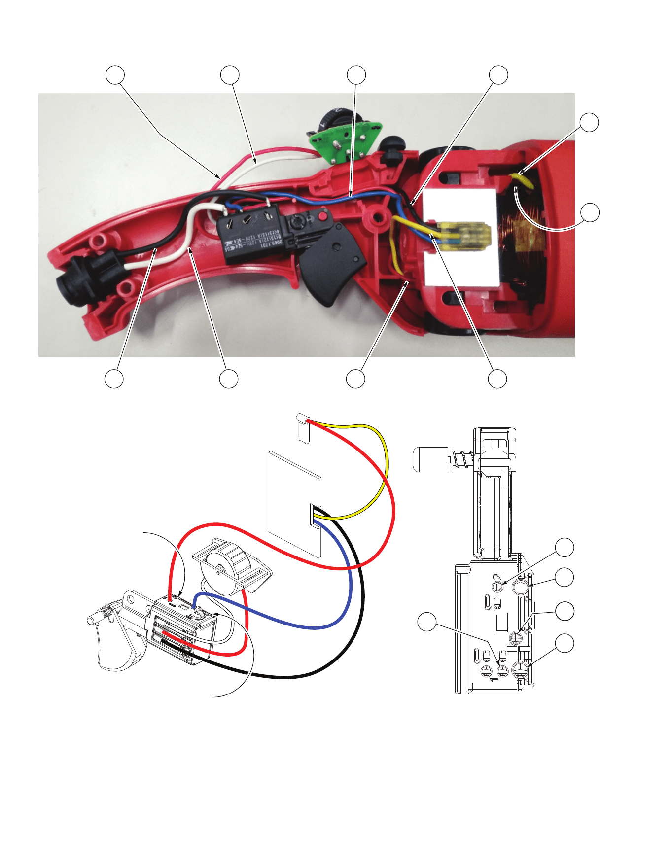
WIRING INSTRUCTION
REVISED BULLETIN DATE
SERVICE PARTS LIST
BULLETIN NO.
STARTING
SERIAL NO.
00
EXAMPLE:
Component Parts (Small #) Are Included
When Ordering The Assembly (Large #).
0
SPECIFY CATALOG NO. AND SERIAL NO. WHEN ORDERING PARTS
CATALOG NO.
MILWAUKEE TOOL
l
www.milwaukeetool.com
13135 W. LISBON RD., BROOKFIELD, WI 53005
Drwg. 2
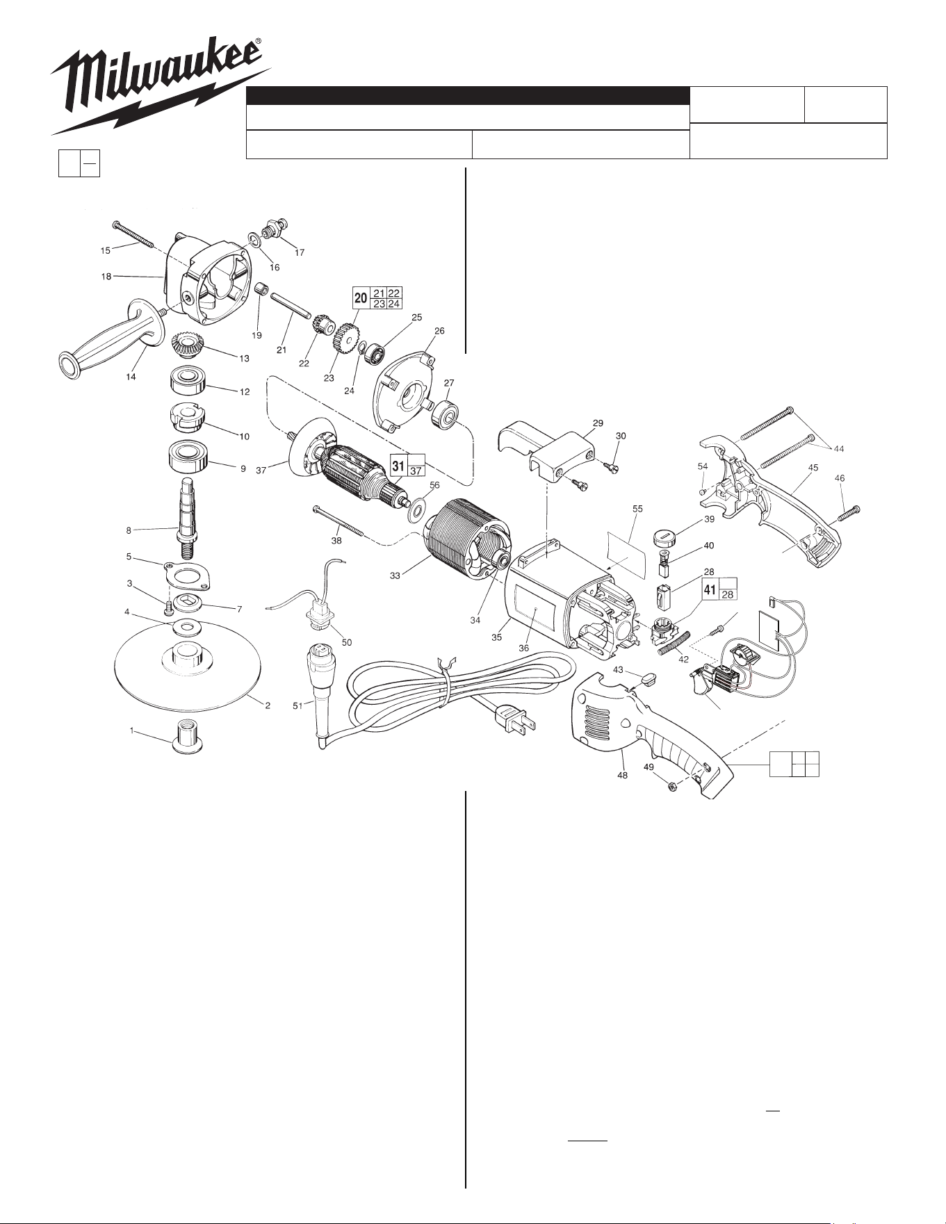
FIG. PART NO. DESCRIPTION OF PART NO. REQ.
1 49-40-0390 Disc Nut (1)
2 49-36-2500 7" Backing Pad (1)
3 06-82-5338 1/4-20 x 1/2" Pan Hd. Slt. Tapt. T-30 (2)
4 45-88-8465 Spindle Washer (1)
5 45-88-7785 Spindle Retaining Washer (1)
7 49-05-0060 Washer Flange (1)
8 38-50-5231 Spindle Shaft (1)
9 02-04-2031 Ball Bearing (1)
10 42-74-0070 Spindle Locking Cog (1)
12 02-04-1747 Ball Bearing (1)
13 32-05-1081 Bevel Gear (1)
14 43-62-1265 Side Handle (1)
15 06-82-7441 10-14 x 1-7/8" Pan Hd. Slt. Plastite T-25 (4)
16 45-88-5320 Flat Washer (1)
17 44-20-0211 Spindle Lock Assembly (1)
18 28-14-1430 Gear Case (1)
19 02-50-2200 Needle Bearing (1)
20 14-73-0130 Intermediate Gear Assy. (1)
21 --------------- Intermediate Shaft (1)
22 --------------- Bevel Gear (1)
23 --------------- Intermediate Gear (1)
24 --------------- External Retaining Ring (1)
25 02-04-0910 Ball Bearing (1)
26 28-28-1565 Diaphragm (1)
27 02-04-1860 Ball Bearing (1)
28 22-20-0660 Brush Tube (2)
54-32-1285
See Reverse Side
54-32-1284
5460
F IG. PART NO. DESCRIPTION OF PART NO. REQ.
29 31-70-0110 Tool Rest (1)
30 45-04-0720 Shoulder Screw (3)
31 16-50-1090 120 Volt Armature (1)
32 06-82-7409 8-16 x 1/2" Pan Hd. Plastite T-20 (1)
33 18-50-0092 120 Volt Field (1)
34 02-04-0845 Ball Bearing (1)
35 --------------- Motor Housing (1)
36 12-20-5500 Service Nameplate Kit (1)
37 22-84-0710 Fan (1)
38 06-82-7375 8-16 x 2-1/2" Pan Hd. Plastite T-20 (2)
39 23-44-0210 Brush Retaining Screw (2)
40 22-18-0680 Carbon Brush Assembly (2)
F IG. PART NO. DESCRIPTION OF PART NO. REQ.
41 22-22-1325 Brush Holder Assembly (2)
42 40-50-7770 Brush Holder Spring (2)
43 42-38-0190 Bumper (1)
44 06-82-2598 10-24 x 2-3/4" Pan Hd. Slt. T-25 (2)
45 --------------- Right Handle Half (1)
46 06-82-2568 10-24 x 7/8" Pan Hd. Slt. T-25 (3)
47 23-66-1941 TSC Switch with Dial/Module Assembly (1)
48 --------------- Left Handle Half (1)
49 06-55-1050 10-24 Hex Nut (5)
50 22-56-0679 Blade Housing Assembly (1)
51 48-76-5010 Cord Set (1)
54 42-38-0181 Rubber Bumper (2)
55 10-98-1810 Warning Label (1)
56 23-16-1700 Commutator Insulator (1)
57 31-50-0548 Handle/Housing Service Kit (1)
FIG. LUBRICATION
18 1-1/4 Oz. Type "Y" Grease No. 49-08-5270, In Grease Cavity.
1-1/2 Oz. Type "B" Grease, No. 49-08-0900, To Build Up Wall of
Grease Around Grease Cavity.
7" HEAVY-DUTY VARIABLE SPEED POLISHER
785D
32
47
35 45
48
57
1
2
3
5
7
9
10
6
4
Red wire from
dial to switch
White wire from
dial to switch
Blue wire from
module to switch
Black wire from
module to switch
Black wire from
blade housing
to switch
White wire from
blade housing
to switch
Red wire from
brush to switch
Yellow wire from module
thru trap to lower brush
Yellow field
wire to top
brush
8
Black field
wire (from
other side)
to switch
Note:
Black field wire #8 is placed
in wire traps under wires
#1, #3 and #4.
10
3
9
4
8
Black wire from
blade housing
assembly here
White wire from
blade housing
assembly here