00
EXAMPLE:
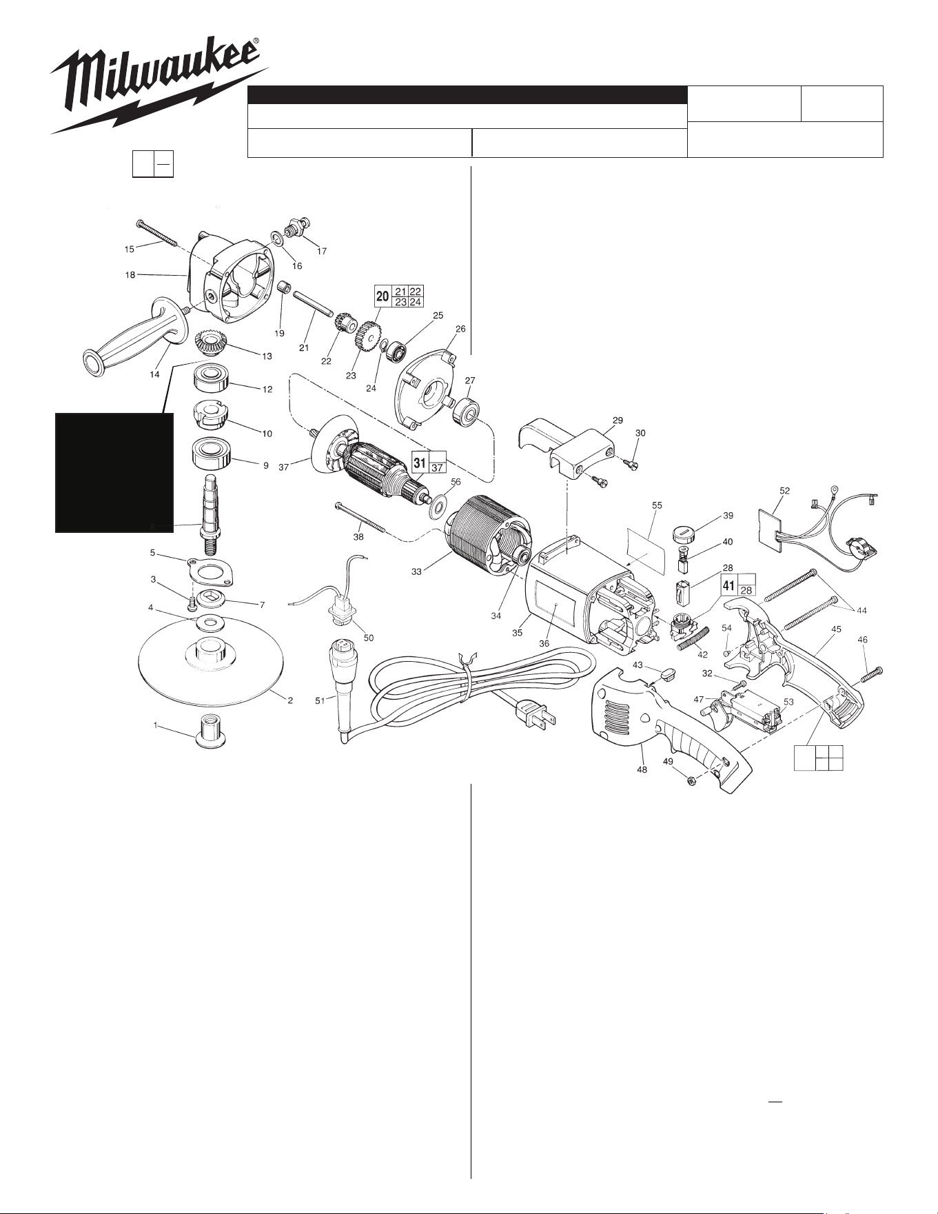
Component Parts (Small #) Are Included
When Ordering The Assembly (Large #).
0
MILWAUKEE ELECTRIC TOOL CORPORATION
13135 W. LISBON RD., BROOKFIELD, WI 53005
Drwg. 6
WIRING INSTRUCTION
REVISED BULLETIN DATE
SERVICE PARTS LIST
BULLETIN NO.
SPECIFY CATALOG NO. AND SERIAL NO. WHEN ORDERING PARTS
STARTING
SERIAL NO.
CATALOG NO.
SERVICE NOTE:
A washer can be
used as a shim
below the bevel
gear #13 to help
reduce tool noise.
Washer should be
.875 OD x .50 ID x
.0078 Thick ±.0015
FIG. PART NO. DESCRIPTION OF PART NO. REQ.
1 49-40-0390 Disc Nut (1)
2 49-36-2500 7" Backing Pad (1)
3 06-82-5338 1/4-20 x 1/2" Pan Hd. Slt. Tapt. T-30 (2)
4 45-88-8465 Spindle Washer (1)
5 45-88-7785 Spindle Retaining Washer (1)
7 49-05-0060 Washer Flange (1)
8 38-50-5231 Spindle Shaft (1)
9 02-04-2031 Ball Bearing (1)
10 42-74-0070 Spindle Locking Cog (1)
12 02-04-1747 Ball Bearing (1)
13 32-05-1081 Bevel Gear (1)
14 43-62-1265 Side Handle (1)
15 06-82-7441 10-14 x 1-7/8" Pan Hd. Slt. Plastite T-25 (4)
16 45-88-5320 Flat Washer (1)
17 44-20-0211 Spindle Lock Assembly (1)
18 28-14-1430 Gear Case (1)
19 02-50-2200 Needle Bearing (1)
20 14-73-0140 Intermediate Gear Assy. (1)
21 --------------- Intermediate Shaft (1)
22 --------------- Bevel Gear (1)
23 --------------- Intermediate Gear (1)
24 --------------- External Retaining Ring (1)
25 02-04-0910 Ball Bearing (1)
26 28-28-1565 Diaphragm (1)
27 02-04-1860 Ball Bearing (1)
28 22-20-0660 Brush Tube (2)
7" HEAVY-DUTY VARIABLE SPEED POLISHER
54-32-1302
F IG. PART NO. DESCRIPTION OF PART NO. REQ.
29 31-70-0110 Tool Rest (1)
30 45-04-0720 Shoulder Screw (3)
31 16-50-1110 120 Volt Armature (1)
32 06-82-7409 8-16 x 1/2" Pan Hd. Plastite T-20 (1)
33 18-50-0091 120 Volt Field (1)
34 02-04-0845 Ball Bearing (1)
35 --------------- Motor Housing (1)
36 12-20-5500 Service Nameplate Kit (1)
37 22-84-0710 Fan (1)
38 06-82-7375 8-16 x 2-1/2" Pan Hd. Plastite T-20 (2)
39 23-44-0210 Brush Retaining Screw (2)
40 22-18-0680 Carbon Brush Assembly (2)
F IG. PART NO. DESCRIPTION OF PART NO. REQ.
41 22-22-1325 Brush Holder Assembly (2)
42 40-50-7770 Brush Holder Spring (2)
43 42-38-0190 Bumper (1)
44 06-82-2598 10-24 x 2-3/4" Pan Hd. Slt. T-25 (2)
45 --------------- Right Handle Half (1)
46 06-82-2568 10-24 x 7/8" Pan Hd. Slt. T-25 (3)
47 23-66-1940 TSC Switch (1)
48 --------------- Left Handle Half (1)
49 06-55-1050 10-24 Hex Nut (5)
50 22-56-0675 Blade Housing Assembly (1)
51 48-76-5010 Cord Set (1)
52 14-20-1035 Dial / Module Assembly (1)
53 05-78-0305 Switch Screw (4)
54 42-38-0181 Rubber Bumper (2)
55 10-98-1810 Warning Label (1)
56 23-16-1700 Commutator Insulator (1)
57 31-50-0548 Handle/Housing Service Kit (1)
FIG. LUBRICATION
18 1-1/4 Oz. Type "Y" Grease No. 49-08-5270, In Grease Cavity.
1-1/2 Oz. Type "B" Grease, No. 49-08-0900, To Build Up Wall
of Grease Around Grease Cavity.
54-32-1301
58-01-0225
802C5540
Aug. 2022
35 45
48
57
MILWAUKEE TOOL
l
www.milwaukeetool.com
13135 W. LISBON RD., BROOKFIELD, WI 53005
Drwg. 7