Installation
Instructions
Natural Gas High Altitude Conversion Instructions
for WB28X29254
For Ranges Operating on Natural Gas at Elevations
More than 6,000 Feet Above Sea Level
WARNING
This conversion must be
performed by a qualified installer or gas supplier
in accordance with the manufacturer’s instructions
and all codes and requirements of the authority
having jurisdiction. Failure to follow instructions
could result in serious injury or property damage.
The qualified agency performing this work
assumes responsibility for the conversion.
IMPORTANT: This kit is designed for ranges
equipped for use with Natural Gas. Use only the
specific orifices called out in these instructions.
Additional orifices may be present.
31-11103-5 07-20 GEA
TOOLS YOU NEEDED FOR CONVERSION
1
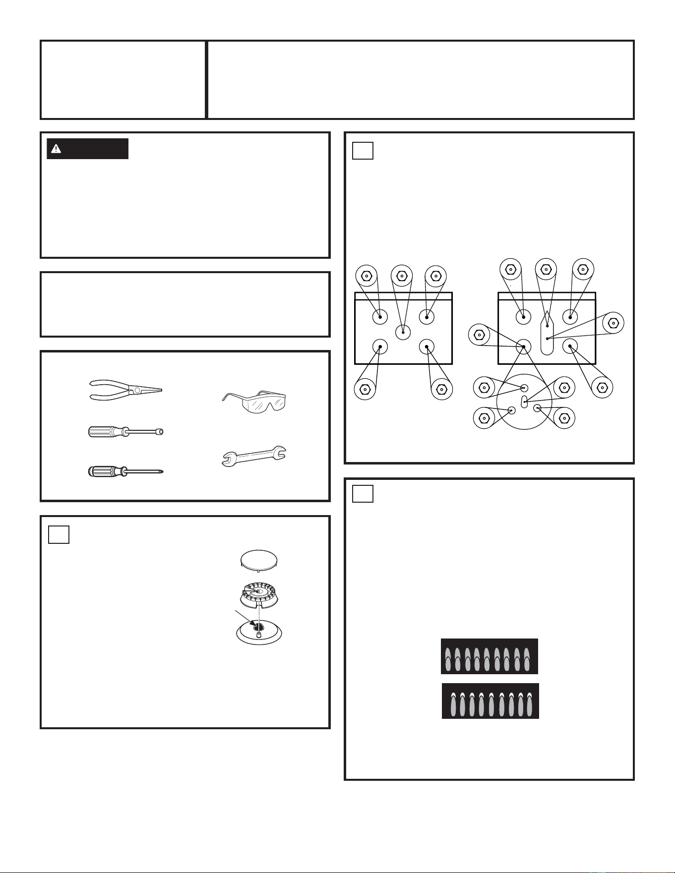
REMOVE TOP BURNER ORIFICES
The orifice spuds needed
to enable the top burners
to operate correctly at high
altitude are in this kit.
A. Remove the top grates,
burner caps and burner
heads.
B. Using a 7 mm (9/32”) nut
driver, remove the top
burner orifice spuds. These are accessed through
the burner opening in the cooktop.
C. .HHSDOORUL¿FHVWKDWDUHUHPRYHGIRUSRVVLEOH
future use.
3
CHECK SURFACE BURNERS
Push and turn a knob to the LITE position. A clicking
sound indicates proper operation of the ignition system.
When lighting any burner, sparks will appear at all
burners but gas flows from only the one selected. Once
air is purged from the supply line, burner should light
within 4 seconds. After burner lights, rotate the knob out
of the LITE position. Try each burner in succession until
all burners have been checked.
Quality of Flames
Determine the
quality of flames
visually. Normal
burner flames
should look like
(A) or (B).
Long, bright yellow flames are not normal. Normal
flames may show signs of an orange tint when well
heated or signs of flickering orange due to particles in
the gas or air.
2
INSTALL HIGH ALTITUDE BURNER
ORIFICES
A. Find your model in the table on page 4. Read the
size stamped on each orifice in the kit and determine
its proper location from the table for your model.
Place each orifice on the maintop next to the burner
opening where it belongs. Not all orifices will be used.
Burner cap
Burner construction
Burner
head
Base
2UL¿FH
spud
located
through
this
opening
Models With
Five Orifices
Models With Six Or More Orifices
1/4” and 7mm Nutdrivers
1/2” wrench
Small Pliers
Philips Screwdriver
Safety Glasses
LR
RR
LF
C
RF
LR
C2
C1
RR
LF
RF
LF3
LF1
LFC
LF2
(on some models)
(on some models)
(A) Soft blue flames—
Normal for natural gas
(B) Yellow tips on
outer cones—
Normal for propane gas
2
31-11103-5
Bake Air
Shutter
Broil Air
Shutter
3
INSTALL HIGH ALTITUDE BURNER
ORIFICES (Cont.)
B. Install the orifices from the kit in their correct locations
using a 7mm (9/32”) nut driver. To prevent leakage,
make sure the orifice spuds are securely screwed
into the gas supply tube. Check the LO flame setting
of cooktop burners by first turning all burners to a
MEDIUM setting. With the other burners operating,
turn the burner to be checked to its LO setting and
observe the flame. If the flame is unstable or goes out
while opening or closing the oven door, refer to the
Propane Conversion Instructions attached to the back
of your range for how to adjust the low flame setting.
Repeat for all burners.
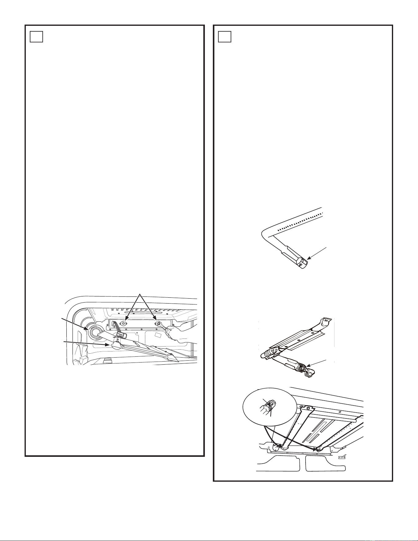
C. If your model has a Dual Broil burner (a burner with
two tubes in the top of the oven), follow steps 1
through 5 below to replace the broil burner orifices.
If not, go to Step D.
1. Remove the oven door for easy access to
the broil burner. See Owner’s Manual for
instructions.
2. Remove the two ¼” hex screws securing the
broil burner and slide forward to expose the broil
orifices on the rear wall. Allow burner to hang
down clear of the broil orifices.
3. Apply a ½” open-end wrench or socket to the
hex base of an orifice. Loosen the orifices by
turning counter-clockwise and remove.
4. Find the two large orifice hoods in the kit.
Install them on the two broil fittings and tighten
until snug.
5. Replace the broil burner over the orifices and
replace screws securing the burner in place.
Replace oven door.
D. Place the old orifice spuds in the plastic bag along
with these instructions and save for possible
future use.
4
ADJUSTING THE BAKE AND BROIL
BURNERS IF NECESSARY
1RUHSODFHPHQWRIRUL¿FHVIRUEDNHDQGEURLOEXUQHUV
(except as noted in 2C) is required to maintain proper
and safe operation of the oven. It is not likely that
adjustment to the back and broil burner air shutters is
QHFHVVDU\XQOHVVÀDPHVDSSHDUH[FHVVLYHO\VRIWRU
yellow or soot is being deposited on the interior surfaces
of the oven. If these conditions are present, make
adjustments to the air shutters as follows.
ACCESSING THE BAKE BURNER AIR SHUTTER
Remove the oven door and storage/warming drawer.
Remove the oven bottom. See Owner’s Manual for
instructions. The bake burner air shutter is located at the
KHDGRIWKHEXUQHUZKHUHLW¿WVRYHUWKHRUL¿FH6RPH
single oven models have a metal cover that must be
removed to access the bake burner air shutter. Double
oven models will require removal of the oven bottom and
ÀDPHVSUHDGHU
ACCESSING THE BROIL BURNER AIR SHUTTER
The broil burner air shutter is located in the upper right
rear corner of the oven. Models with a dual broil burner
have two shutters.
Oven
light
%URLORUL¿FHV
Broil burner
assembly
1. Loosen screw
2. Open air shutter
31-11103-5
3
4
ADJUSTING THE BAKE AND BROIL
BURNERS IF NECESSARY (Cont.)
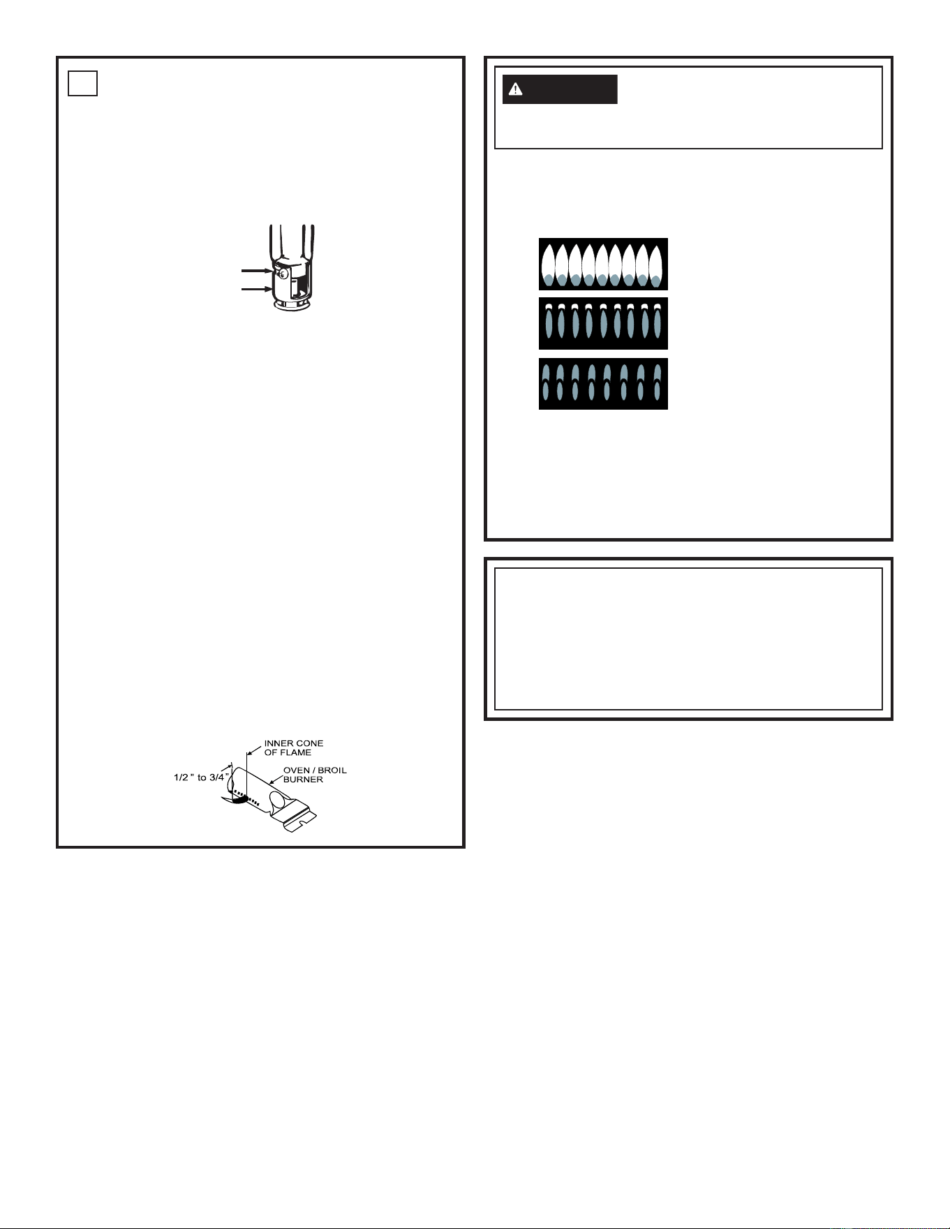
ADJUSTING THE AIR SHUTTER SETTINGS FOR
BAKE AND BROIL BURNERS
1. Loosen the air shutter screw with a Phillips
screwdriver.
2. Rotate the shutter to increase the open area as
UHTXLUHG<RXU¿QDOVHWWLQJZLOOYDU\
3. Retighten the air shutter screw.
4. Reinstall the oven door.
127(%DNHDQGEURLOÀDPHVVKRXOGEHREVHUYHG
ZLWKWKHGRRUFORVHGWRSURSHUO\FKHFNÀDPH
characteristics.
5. Turn on the bake or broil burner and let it operate for
about a minute.
$V\RXZDWFKWKHÀDPHWKURXJKWKHRYHQGRRU
window, check the following:
D ,IWKHÀDPHVDUHVRIWDQG\HOORZRSHQWKHDLU
shutter more.
E ,IWKHÀDPHVEORZDZD\IURPWKHEXUQHUFORVHWKH
air shutter more.
7KHLQQHUFRQHRIWKHÀDPHVKRXOGEHDSSUR[LPDWHO\
½” to ¾” long for the bake and broil burners. The
FRPEXVWLRQTXDOLW\RIWKHEXUQHUÀDPHVPXVWEH
determined visually.
WARNING
If you attempt to measure the
inner cone of the flame, please use caution: burns
could result.
8. After all adjustments are made and the results are
VDWLVIDFWRU\UHSODFHWKHÀDPHVSUHDGHURYHQERWWRP
and the storage/warming drawer.
IN SOME CASES:
• Dust particles in the gas line may cause an orange
ÀDPHDW¿UVWEXWWKLVZLOOVRRQGLVDSSHDU
• With propane, some yellow tipping on the outer cones
is normal, especially as burner becomes warm.
NOTICE:
2QFHWKHFRQYHUVLRQLVFRPSOHWHDQGFRQ¿UPHG¿OO
out the High Altitude sticker and include your name,
organization and date conversion was made. Apply
the sticker to the range near the rating label to alert
others in the future that this appliance has been
converted for High Altitude.
Screw
Air shutter
(A) Yellow flames:
Further Adjustment
Required
(B) Yellow tips on
outer cones:
Normal for Propane Gas
(C) Soft blue flames:
Normal for Natural Gas
4
31-11103-5
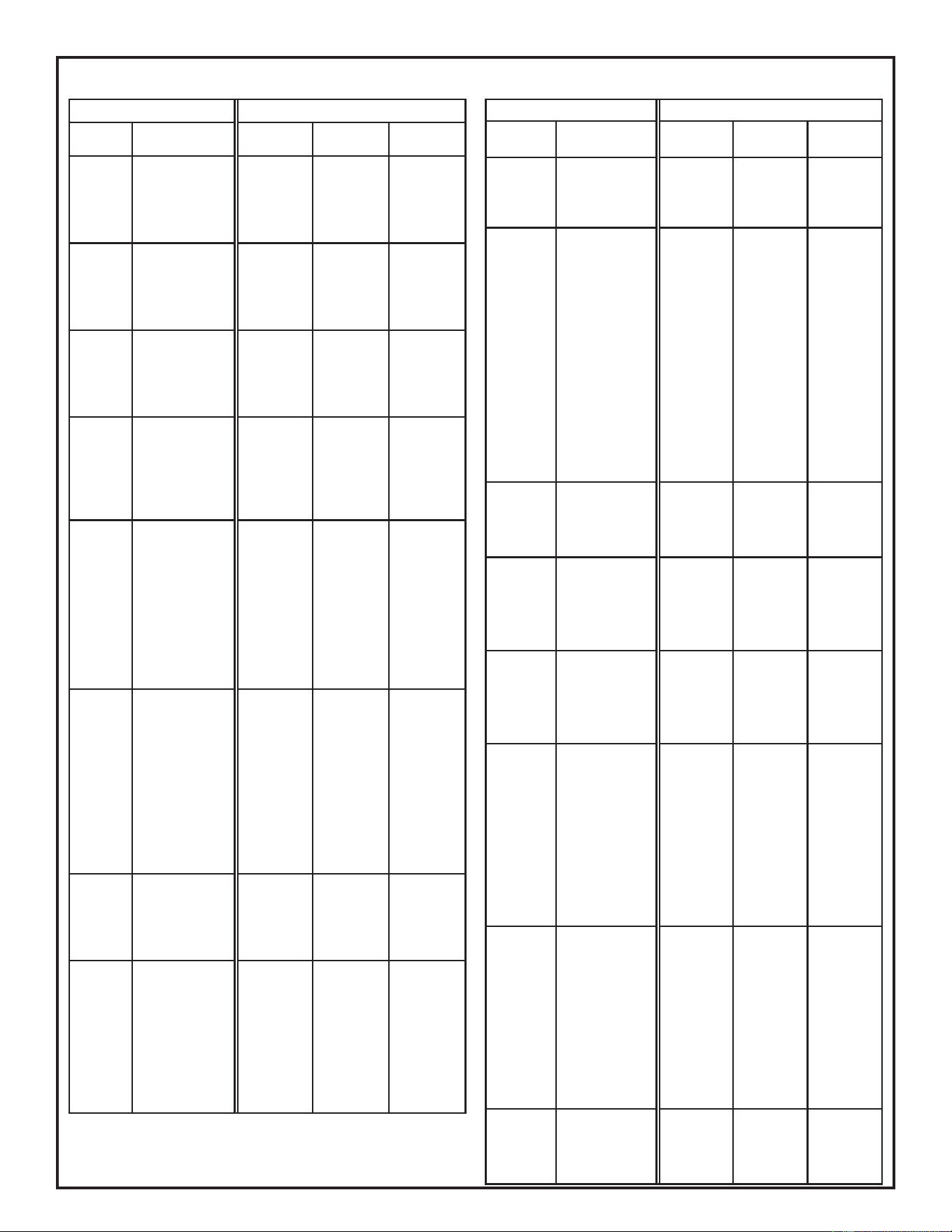
ORIFICE SPUD PLACEMENT BY MODEL
8VHQDWXUDOJDVRUL¿FHVKLSSHGZLWKUDQJH
High Altitude Natural Gas
Model
Burner
Location
Nominal
Rate
Orifice
Size (mm)
Markings
JGB660
JGB700
JGB860
JGB735
RF
RR
C
LF
LR
9,500
12,000
10,000
18,000
5,000
1.33
1.44
1.33
1.85
0.94
H133
H144
H133
185N
H94
JGB720 RF
RR
C
LF
LR
15,000
9,500
8,000
18,000
5,000
1.78*
1.33
1.27*
1.85
0.94
178N*
H133
127N*
185N
H94
PGB911 RF
RR
C
LF
LR
18,000
9,500
10,000
18,000
5,000
1.85
1.33
1.33
1.85
0.94
185N
H133
H133
185N
H94
PGB960 RF
RR
C1
C2
LF
LR
18,000
9,500
9,500
8,800
18,000
5,000
1.85
1.33
1.33
1.29
1.85
0.94
185N
H133
H133
H129
185N
H94
PGB930
P2B940
RF
RR
C1
C2
LF
LF1
LF2
LF3
Center
LR
18,000
9,500
9,500
8,800
20,000
5,000
1.85
1.33
1.33
1.29
0.99
0.99
0.99
0.66
0.94
185N
H133
H133
H129
H99
H99
H99
H66
H94
PGB940
PGB980
RF
RR
C1
C2
LF
LF1
LF2
LF3
Center
LR
Broil (2)
18,000
9,500
9,500
8,800
20,000
5,000
16,500
1.85
1.33
1.33
1.29
0.99
0.99
0.99
0.66
0.94
0.046 (in)
185N
H133
H133
H129
H99
H99
H99
H66
H94
046N
JGBS66
JGBS86
RF
RR
C
LF
LR
9,500
12,000
10,000
15,000
5,000
1.33
1.44
1.33
1.78*
0.94
H133
H144
H133
178N*
H94
PGB935
P2B935
RF
RR
LF
LF1
LF2
LF3
Center
LR
C
18,000
9,500
20,000
5,000
10,000
1.85
1.33
0.99
0.99
0.99
0.63
0.94
1.33
185N
H133
H99
H99
H99
63N*
H94
H133
High Altitude Natural Gas
Model
Burner
Location
Nominal
Rate
Orifice
Size (mm)
Markings
JGB645 RF
RR
LF
LR
12,000
9,500
15,000
5,000
1.44
1.33
1.78*
0.94
H144
H133
178N*
H94
AGBS45
RGB526
RGB530
RGB780
JGBS60
JGBS61
JGB450
JGB635
RGBS100
RGBS200
RGBS300
RGBS400
JGBS10
JGBS30
RF
RR
LF
LR
13,000
5,000
9,500
9,500
1.44
0.94
1.33
1.33
H144
H94
H133
H133
RGAS200
RGAS300
JGAS640
QGAS740
RF
RR
LF
LR
15,000
5,000
9,500
9,500
1.78*
0.94
1.33
1.33
178N*
H94
H133
H133
JGSS66 RF
RR
C
LF
LR
15,000
9,500
10,000
15,000
5,000
1.78*
1.33
1.33
1.78*
0.94
178N*
H133
H133
178N*
H94
JGS760
CGB500
CGB550
JGSS86
RF
RR
C
LF
LR
15,000
9,500
10,000
18,000
5,000
1.78*
1.33
1.33
1.85
0.94
178N*
H133
H133
185N
H94
PGS930
P2S930
PGS960
RF
RR
C1
C2
LF
LF1
LF2
LF3
Center
LR
15,000
9,500
9,500
6,800
21,000
5,000
1.78*
1.33
1.33
1.17
1.09
1.09
1.09
0.63*
0.94
178N*
H133
H133
117N
109N
109N
109N
63N
H94
CGS986
CGS995
C2S986
C2S995
CGS700
CGS750
C2S900
C2S950
RF
RR
C1
C2
LF
LF1
LF2
LF3
Center
LR
15,000
12,000
9,500
9,500
21,000
5,000
1.78*
1.44
1.33
1.33
1.09
1.09
1.09
0.63*
0.94
178N*
H144
H133
H133
109N
109N
109N
63N
H94
QGSS740 RF
RR
LF
LR
15,000
9,500
15,000
5,000
1.78*
1.33
1.78*
0.94
178N*
H133
178N*
H94

