deutsch / english
C ONE
1-Kanal High-End Verstärker mit integrierter,
aktiver Frequenzweiche und 1 Ohm Stabilität
1-channel high-end amplier with integrated,
active crossover and 1 Ohm stability

2
Sehr geehrter Kunde,
Wir gratulieren Ihnen zum Kauf dieses hochwer-
tigen HELIX Verstärkers.
Audiotec Fischer setzt mit der HELIX C ONE neue
Maßstäbe im Bereich der Verstärkertechnik.
Dabei protieren Sie als Kunde direkt von unserer
mehr als 30-jährigen Erfahrung in der Forschung
und Entwicklung von Audiokomponenten.
Dieser Verstärker wurde von uns nach neuesten
technischen Erkenntnissen entwickelt und zeichnet
sich durch hervorragende Verarbeitung und eine
überzeugende Anwendung ausgereifter Technolo-
gien aus.
Viel Freude an diesem Produkt wünscht Ihnen das
Team von
AUDIOTEC FISCHER
Allgemeines zum Einbau von HELIX-Kompo-
nenten
Um alle Möglichkeiten des Produktes optimal aus-
schöpfen zu können, lesen Sie bitte sorgfältig die
nachfolgenden Installationshinweise. Wir garantie-
ren, dass jedes Gerät vor Versand auf seinen ein-
wandfreien Zustand überprüft wurde.
Vor Beginn der Installation unterbrechen Sie
den Minusanschluss der Autobatterie.
Wir empfehlen Ihnen, die Installation von einem
Einbauspezialisten vornehmen zu lassen, da der
Nachweis eines fachgerechten Einbaus und An-
schlusses des Gerätes Voraussetzung für die
Garantieleistungen sind.
Installieren Sie Ihren Verstärker an einer trocke-
nen Stelle im Auto und vergewissern Sie sich, dass
der Verstärker am Montageort genügend Kühlung
erhält. Montieren Sie das Gerät nicht in zu kleine,
abgeschlossene Gehäuse ohne Luftzirkulation
oder in der Nähe von wärmeabstrahlenden Teilen
oder elektronischen Steuerungen des Fahrzeuges.
Im Sinne der Unfallsicherheit muss der Verstärker
professionell befestigt werden. Dieses geschieht
über Schrauben, die in eine Montageäche ein-
geschraubt werden, die wiederum genügend Halt
bieten muss.
Bevor Sie die Schrauben im Montagefeld befesti-
gen, vergewissern Sie sich, dass keine elektrischen
Kabel und Komponenten, hydraulische Bremslei-
tungen, der Benzintank etc. dahinter verborgen
sind. Diese könnten sonst beschädigt werden. Ach-
ten Sie bitte darauf, dass sich solche Teile auch in
der doppelten Wandverkleidung verbergen können.
Allgemeines zum Anschluss des C ONE Ver-
stärkers
Der Verstärker darf nur in Kraftfahrzeuge eingebaut
werden, die den 12 V-Minuspol an Masse haben.
Bei anderen Systemen können der HELIX Verstär-
ker und die elektrische Anlage des Kfz beschädigt
werden. Die Plusleitung für die gesamte Anlage
sollte in einem Abstand von max. 30 cm von der
Batterie mit einer Hauptsicherung abgesichert wer-
den. Der Wert der Sicherung errechnet sich aus der
maximalen Stromaufnahme der Car-Hi Anlage.
Verwenden Sie zum Anschluss des Verstärkers
an die Stromversorgung des Fahrzeugs aus-
schließlich geeignete Kabel mit ausreichen-
dem Kabelquerschnitt. Die Sicherungen im
Verstärker dürfen nur mit den gleichen Werten
(3 x 30 A) ersetzt werden, um eine Beschädi-
gung des Gerätes zu verhindern. Höhere Werte
können zu gefährlichen Folgeschäden führen!
Die Kabelverbindungen müssen so verlegt sein,
dass keine Klemm-, Quetsch- oder Bruchgefahr be-
steht. Bei scharfen Kanten (Blechdurchführungen)
müssen alle Kabel gegen Durchscheuern gepols-
tert sein. Ferner darf das Versorgungskabel niemals
mit Zuleitungen zu Vorrichtungen des Kfz (Lüfter-
motoren, Brandkontrollmodulen, Benzinleitungen
etc.) verlegt werden.
Herzlichen Glückwunsch!
Allgemeine Hinweise
3
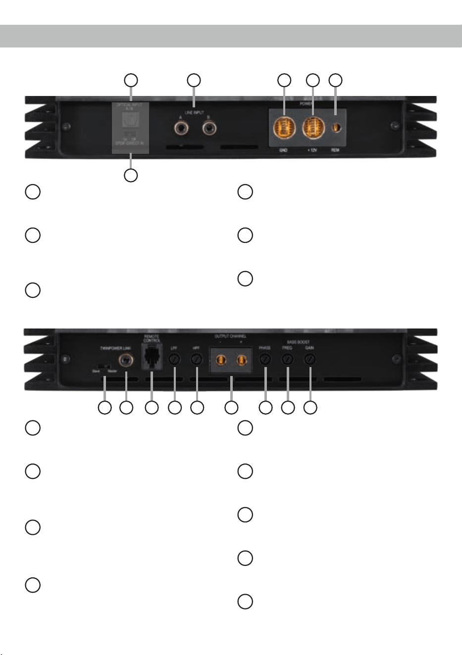
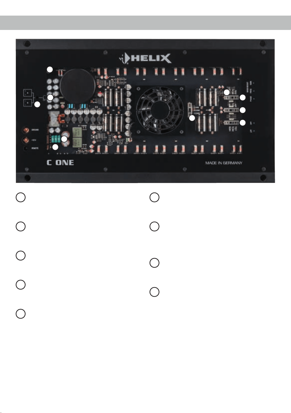
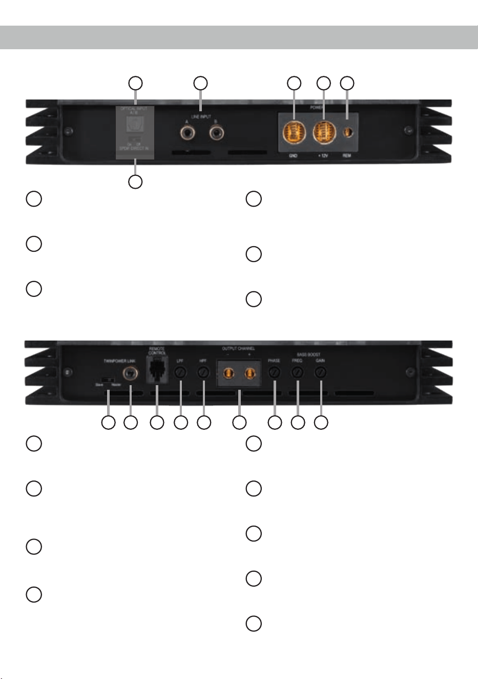
Anschluss- und Bedienelemente
1
Optical Input (optional)
Optischer Digitaleingang im SPDIF-Format
für digitale Stereosignale.
2
SPDIF Direct In-Schalter (optional)
Zur direkten Weiterleitung des Digitalsignals
vom integrierten DA-Wandler zum internen
Leistungsverstärker.
3
Line Input
Cinch-Eingänge zum Anschluss eines
Vorverstärkersignals.
4
GND
Anschluss des Massekabels (Minuspol der
Batterie oder Fahrzeugchassis).
5
+12 V
Anschluss für das Versorgungsspannungs-
kabel +12 V der Batterie.
6
REM
Anschluss für die Remoteleitung.
7
TwinPower Link-Schalter
Schalter um zwei C ONE Verstärker im
Brüc kenbetrieb zu betreiben.
8
Mono Cinch In- / Output
Mono Cinch-Signalein- oder -ausgang für
den Brückenbetrieb im TwinPower Link-
Modus.
9
Remote Control
Eingang zum Anschluss einer optional er-
hältlichen Fernbedienung zur Lautstärkere-
gelung.
10
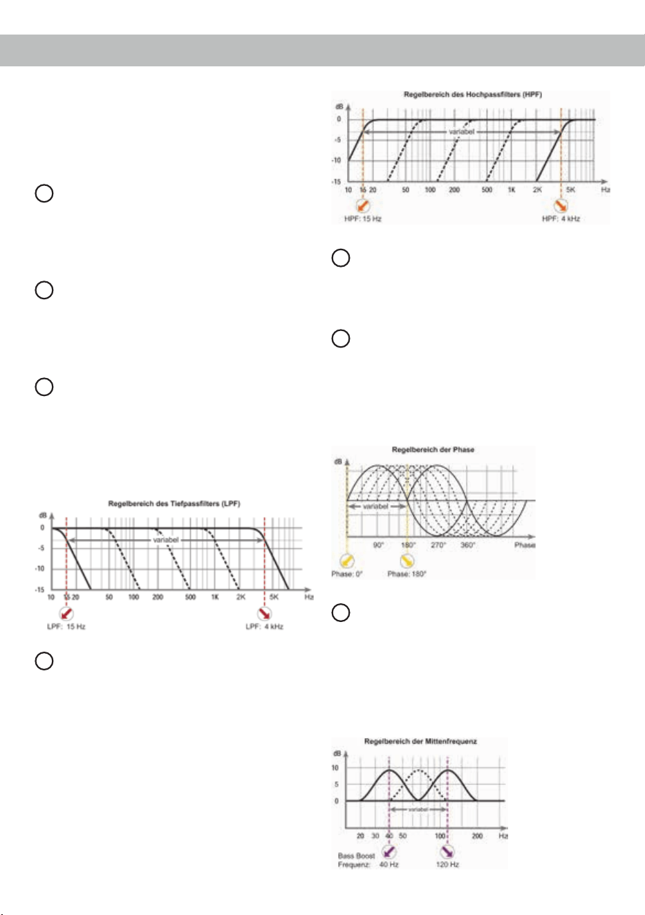
LPF
Regler zum Einstellen des Tiefpasslters von
15 Hz bis 4.000 Hz.
11
HPF
Regler zum Einstellen des Hochpasslters
von 15 Hz bis 4.000 Hz.
12
Output Channel
Lautsprecherausgang für den Anschluss von
Lautsprechern.
13
Phase
Regler zum Einstellen der Phase von 0° bis
180°.
14
Bass Boost Frequenz
Regler zum Einstellen der Mittenfrequenz
des Bass Boost von 40 bis 120 Hz.
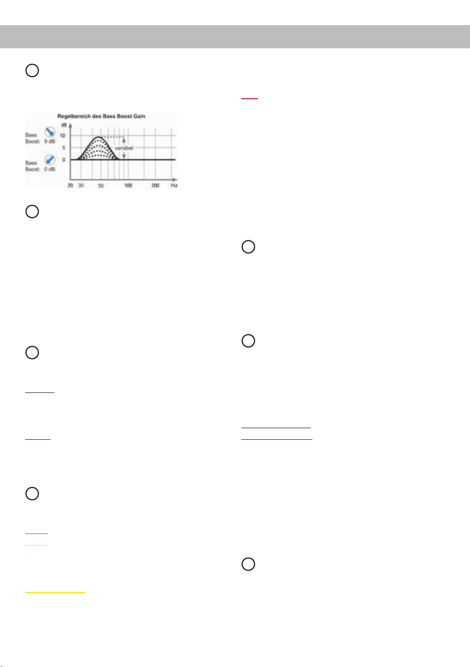
15
Bass Boost Gain
Regler zum Einstellen der Bassanhebung
von 0 bis 9 dB.
8 9 127 10 11
1 4 5 6
C ONE Seitenansicht mit optional erhältlichem HELIX Digital Input Modul HDM 1
3
1513 14
2
optional
4
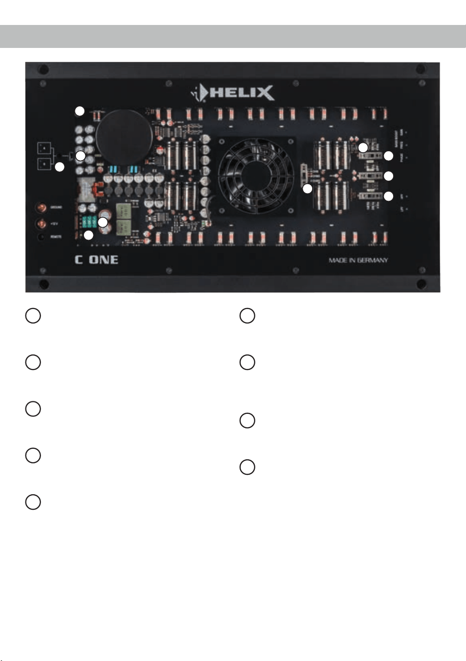
Anschluss- und Bedienelemente
16
Levelregler
Regler zum Einstellen der Eingangsempnd-
lichkeit des Line Input.
17
Input Mode-Schalter (Stereo / Mono)
Schalter zur Anpassung des Verstärkers an
die Anzahl der belegten Eingänge.
18
Power & Protect LED
Die Power & Protect LED zeigt den
Betriebszustand des Verstärkers an.
19
Sicherungen
Eingangssicherungen zum Schutz vor
geräteinternen Fehlern.
20
Impedanzeinstellungsschalter
Schalter zum Anpassen des Verstärkers an
die Impedanz des angeschlossenen Laut-
sprechers.
21
LED-Schalter
Schalter zum Ein- und Ausschalten der LED-
Beleuchtung.
22
Grenzfrequenz-Schalter
Schalter zum Einstellen der maximalen, obe-
ren Grenzfrequenz des entsprechenden Fre-
quenzweichenlters.
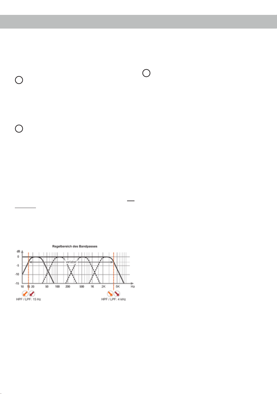
23
X-Over-Schalter
Schalter zum Aktivieren der verschiedenen
Filter.
24
HDM Slot
Steckplatz für das optional erhältliche HELIX
Digital Input Modul HDM 1.
16
19
17
20
18
22
22
21
24
23

5
1
Optical Input (optional)
Optischer Eingang im SPDIF-Format zum An-
schluss von Signalquellen mit digitalem Ausgang.
Die „Sampling Rate“ dieses Eingangs muss zwi-
schen 28 - 96 kHz liegen.
Hinweis: Der Digitaleingang ist nicht Bestandteil
der Serienausstattung. Dieser kann ausschließlich
durch das optional erhältliche HELIX Digital Input
Modul HDM 1 nachgerüstet werden.
Wichtig: Das digitale Audiosignal einer Quelle ist
üblicherweise nicht lautstärkegeregelt. Das bedeu-
tet, dass an den Ausgängen der C ONE der volle
Pegel anliegt.
Dies kann im Extremfall die angeschlossenen Laut-
sprecher zerstören. Wir raten deshalb dringend
dazu, nur lautstärkegeregelte Signalquellen anzu-
schließen!
Hinweis: Es können ausschließlich Stereosignale
und keine MP3- oder Dolby-codierten Daten verar-
beitet werden!
Hinweis: Eine gleichzeitige Verwendung des op-
tischen Eingangs zusammen mit den Vorverstärker-
eingängen ist möglich.
2
SPDIF Direct In-Schalter (optional)
Mit Hilfe des SPDIF Direct In-Schalters können die
Eingangsstufen der C ONE umgangen und das am
optischen Eingang (Optical Input) anliegende Digi-
talsignal vom integrierten DA-Wandler direkt und
verlustfrei zum internen Leistungsverstärker weiter-
geleitet werden.
Um die direkte Signalweiterleitung zu aktivieren,
muss die Schalterposition des SPDIF Direct In-
Schalters auf „On“ geändert werden.
Hinweis: Die SPDIF Direct In-Funktion gehört
nicht zur Se ri en aus stat tung der C ONE und ist aus-
schließlich in dem optional erhältlichen HELIX Digi-
tal Input Modul HDM 1 enthalten.
Hinweis: Der Schalter beeinusst ausschließlich
die Signalführung des optischen Eingangs.
Hinweis: Für die direkte Signalweiterleitung muss
der Verstärker im Fullrange-Modus betrieben wer-
den. Ändern Sie dazu die Schalterposition des X-
Over-Schalters auf „FULL“ (Seite 8, Punkt 23).
Hinweis: Steht der Schalter auf „On“, sind die Vor-
verstärker-Signaleingänge sowie der Levelregler
(16) ohne Funktion!
3
Line Input
2-Kanal Vorverstärkereingang zum Anschluss von
Signalquellen, wie z.B. Radios, die mit dem / den
Vorverstärkerausgang / -ausgängen bzw. Line Out-
puts der Signalquelle verbunden werden können.
4
GND
Das Massekabel sollte am zentralen Massepunkt
(dieser bendet sich dort wo der Minuspol der Bat-
terie zum Metallchassis des Kfz geerdet ist) oder an
einer blanken, von Lackresten befreiten Stelle des
Kfz-Chassis angeschlossen werden. Der empfohle-
ne Querschnitt beträgt mindestens 16 mm².
5
+12 V
Das +12 V Versorgungskabel ist am Pluspol der
Batterie anzuschließen. Der empfohlene Quer-
schnitt beträgt mindestens 16 mm².
6
REM
Die Remoteleitung wird mit dem Remote-Ausgang /
Antennenanschluss des Steuergerätes (Radio) ver-
bunden. Dieser ist nur aktiviert, wenn das Steuer-
gerät eingeschaltet ist. Somit wird der Verstärker
mit dem Steuergerät ein- und ausgeschaltet. So-
fern sich ein zusätzlicher digitaler Signalprozessor
(DSP) im Signalweg zwischen Radio und Verstär-
ker bendet, muss der Remote-Ausgang des DSP
zum Einschalten der C ONE verwendet werden.
7
TwinPower Link-Schalter
Die C ONE lässt sich über den TwinPower Link
mit einer zweiten C ONE verschalten, um die Aus-
gangsleistung, je nach Lautsprecherkonguration,
mehr als zu verdoppeln.
Um zwei Verstärker im TwinPower Link-Betrieb zu
betreiben, werden diese über die In / Out Buchse
(siehe Seite 6, Punkt 8; Mono Cinch In- / Output) mit
einem Cinchkabel verbunden.
Der Verstärker, der auf Master geschaltet ist, über-
nimmt nun die komplette Regelung (Aktivweiche,
Bass Boost usw.).
Alle Filtereinstellungen des Verstärkers im Slave-
Modus werden dabei deaktiviert.
Wichtig: An beiden Verstärkern muss die gleiche
Impedanz eingestellt sein (siehe Seite 7, Punkt 20;
Impedanzeinstellungsschalter)
Achtung: Bitte immer darauf achten das ein Ver-
stärker auf Master und der andere auf Slave ge-
Inbetriebnahme und Funktionen
6
schaltet ist. In diesem Modus liegt die Minimalim-
pedanz bei 2 Ohm.
Hinweis: Wird der Verstärker einzeln betrieben,
muss die Schalterstellung „Master“ gewählt werden.
Kongurationsbeispiele nden Sie auf Seite 13.
8
Mono Cinch In- / Output
Dieser Anschluss dient als Signalein- oder -aus-
gang zum Anschluss eines weiteren C ONE Ver-
stärkers im TwinPower Link-Betrieb (siehe Seite 5,
Punkt 7; TwinPower Link-Schalter).
9
Remote Control
Eingang zum Anschluss einer optional erhältlichen
Fernbedienung. Mit Hilfe dieser Fernbedienung
lässt sich die Lautstärke des Subwoofers kontrol-
lieren.
10
LPF
Mit Hilfe dieses Reglers kann eine Feineinstellung
des Tiefpasslters von 15 Hz bis 4.000 Hz vorge-
nommen werden. Stellen Sie bitte immer zuerst die
maximal obere Grenzfrequenz mit Hilfe des ent-
sprechenden Schalters ein (siehe Seite 8, Punkt 22;
Grenzfrequenz-Schalter).
11
HPF
Mit Hilfe dieses Reglers kann eine Feineinstel-
lung des Hochpasslter von 15 Hz bis 4.000 Hz
vorgenommen werden. Stellen Sie bitte immer
zuerst die maximal obere Grenzfrequenz mit Hilfe
des entsprechenden Schalters ein (siehe Seite 8,
Punkt 22; Grenzfrequenz-Schalter).
12
Output Channel
Dieser Anschluss dient als Lautsprecherausgang.
Die minimale Lastimpedanz darf 1 Ohm nicht un-
terschreiten.
13
Phase
Mit Hilfe dieses Reglers kann die Phase von 0° bis
180° eingestellt werden. Dies ermöglicht eine bes-
sere Ankopplung des Subwoofers an die Tieftonwie-
dergabe der restlichen Lautsprechersysteme und
verhindert ein Auslöschen der tiefen Frequenzen
aufgrund falscher Phasenlage.
14
Bass Boost Frequenz
Mit Hilfe dieses Reglers kann die Mittenfrequenz
des Bass Boost von 40 Hz bis 120 Hz eingestellt
werden. Mit dem Regler 15 kann diese dann um
0 bis 9 dB angehoben werden. Dies ist sinnvoll,
wenn bestimmte Frequenzen des Subwoofers oder
Kickbasses hervorgehoben oder korrigiert werden
sollen.
Inbetriebnahme und Funktionen
7
15
Bass Boost Gain
Mit Hilfe dieses Reglers kann die mit Regler 14 ein-
gestellte Bassmittenfrequenz um 0 bis 9 dB ange-
hoben werden.
16
Levelregler
Mit Hilfe dieses Reglers kann die Eingangsempnd-
lichkeit an die Ausgangsspannung der angeschlos-
senen Signalquelle angepasst werden. Dieser
Regler ist kein Lautstärkeregler, sondern dient nur
der Anpassung. Der Regelbereich liegt zwischen
0,5 - 8 Volt.
Die Einstellung des Reglers beeinusst ebenfalls
den Digitaleingang des optional erhältlichen HDM
Moduls, wenn nicht dessen SPDIF Direct In-Schal-
ter auf „On“ steht.
17
Input Mode-Schalter (Stereo/Mono)
Dieser Schalter dient zur Anpassung des Verstär-
kers an die Anzahl der belegten Eingänge.
Stereo: Wählen Sie diese Schalterstellung, wenn
beide Eingangskanäle (A und B) belegt sind. Aus
dem Stereosignal wird dann ein optimiertes Sum-
mensignal gebildet.
Mono: Im Mono-Betrieb muss nur der Eingangska-
nal A belegt werden, beispielsweise wenn nur ein
Monosignal für Subwoofer anwendungen zur Verfü-
gung steht.
18
Power & Protect LED
Die Power & Protect LED zeigt den Betriebszustand
des Verstärkers an.
Grün: Verstärker eingeschaltet und betriebsbereit.
Gelb: Überhitzung des Verstärkers. Die interne
Temperaturüberwachung schaltet das Gerät ab, bis
ein sicherer Betrieb wieder gewährleistet werden
kann.
Gelb blinkend: Sicherungen im Inneren des Ge-
räts zerstört. Prüfen Sie die Sicherungen und tau-
schen diese gegebenenfalls aus. Die Sicherungen
im Verstärker dürfen nur mit den gleichen Werten
(3 x 30 Ampere) ersetzt werden, um eine Beschä-
digung des Gerätes zu verhindern. Höhere Werte
können zu gefährlichen Folgeschäden führen!
Rot: Es besteht eine Fehlfunktion des Verstärkers.
Diese Fehlfunktion kann unterschiedliche Ursachen
haben, da die C ONE mit verschiedenen elektro-
nischen Schutzschaltungen ausgestattet ist. Diese
schalten den Verstärker bei Über- und Unterspan-
nung, Kurzschluss am Lautsprecherausgang und
Fehlanschluss ab. Prüfen Sie in diesem Fall alle
Anschlüsse auf Fehler, wie z.B. Kurzschlüsse, feh-
lerhafte Verbindungen oder Falscheinstellungen.
Sollte sich der Verstärker nach Beseitigung der
Fehlerquelle nicht wieder einschalten lassen, liegt
ein Defekt vor.
19
Sicherungen
Die Eingangssicherungen sind parallel geschaltet
und schützen vor einem geräteinternen Fehler, d.h.
die Anlage muss mit einer zusätzlichen Sicherung
in Nähe der Batterie (max. 30 cm entfernt) abgesi-
chert werden. Der Sicherungswert für den Verstär-
ker beträgt 3 x 30 Ampere.
20
Impedanzeinstellungsschalter
Über den Impedanzeinstellungsschalter muss nach
Anschluss des Lautsprechersystems zwingend die
entsprechende Impedanz (4 Ohm, 2 Ohm oder
1 Ohm) eingestellt werden.
Werden mehrere Lautsprecher angeschlossen,
lässt sich die Impedanz in etwa wie folgt errechnen:
Reihenschaltung: Z ges = Z x n
Parallelschaltung: Z ges = Z / n
(n = Anzahl der Lautsprecher; Z = Lautsprecherim-
pedanz)
Hinweis: Bei Verwendung von Lautsprechern
mit einer Impedanz von 3 Ohm ist die Einstellung
„4 Ohm“ zu wählen.
Wichtig: Im TwinPower Link-Betrieb muss an bei-
den Verstärkern die gleiche Impedanz eingestellt
werden (siehe Seite 5, Punkt 7; TwinPower Link-
Schalter).
21
LED-Schalter
Dieser Schalter dient zum Ein- und Ausschalten der
erweiterten LED Beleuchtung des Verstärkers. Die-
ser Schalter hat keine Auswirkungen auf die LEDs
unterhalb des Lüfters, die als extrem rauscharme
Stromquellen in den Endstufentreibern zum Einsatz
kommen. Auch die Funktionalität der Power & Pro-
8
tect LED bleibt hiervon unberührt.
Hinweis: Die Anzahl der leuchtenden LEDs ist von
den am Verstärker vorgenommenen Einstellungen
(beispielsweise MONO oder STEREO Modus) ab-
hängig.
22
Grenzfrequenz-Schalter
Mit Hilfe dieser Schalter kann die maximal obere
Grenzfrequenz für den Hochpasslter (HFP) und
Tiefpasslter (LPF) eingestellt werden. Eine Fein-
abstimmung kann anschließend mit den Reglern 10
(LPF) und 11 (HPF) vorgenommen werden.
23
X-Over-Schalter
Zur Umschaltung der internen, aktiven Frequenz-
weiche auf Hochpass, Fullrange oder Bandpass.
Wird der X-Over-Schalter auf HPF (Hochpassl-
ter) gestellt, so kann mit Hilfe des entsprechenden
Grenzfrequenz-Schalters (22) und Reglers (11 /
HPF) die Übernahmefrequenz für den Hochpass
eingestellt werden. Bei Schalterstellung FULL ist
die interne Frequenzweiche nicht aktiv.
Bei Schalterstellung BPF wird in jedem Fall ein
Bandpass gebildet. Das Hochpasslter ist dabei im-
mer aktiv. Mit dem entsprechenden Grenzfrequenz-
Schalter (22) und Regler 11 (HPF) wird der Hoch-
pass und mit dem entsprechenden Schalter 22 und
Regler 10 (LPF) der Tiefpass eingestellt. So kann
jeder beliebige Bandpass zwischen 15 Hz und
4.000 Hz eingestellt werden.
Achtung: Bitte vergewissern Sie sich, dass beim
Einstellen eines Bandpasses die Übernahmefre-
quenzen von Hoch- und Tiefpass mindestens zwei
Oktaven auseinander liegen, um einen Pegelverlust
zu vermeiden! Das heißt: Wird das Tiefpasssignal
z.B. auf 320 Hz eingestellt, so sollte der Hochpass
um mindestens zwei Oktaven tiefer auf ca. 80 Hz
eingestellt werden. (1 Oktave = Frequenzverdopp-
lung oder Frequenzhalbierung). Beim Anschluss
eines Basslautsprechers empfehlen wir, den Hoch-
passregler (Regler 11 / HPF) als regelbaren Subso-
niclter / tierequenten Hochpasslter zu benutzen
oder auf Linksanschlag (15 Hz) zu drehen, um so
einen Subsoniclter zu erhalten.
24
HDM Slot
Der HDM Slot dient zur Montage des optional er-
hältlichen HELIX Digital Input Moduls HDM 1.
Dieses erweitert die C ONE um einen optischen
Digitaleingang im SPDIF-Format inkl. SPDIF Direct
In-Schalter.
Mit Hilfe des SPDIF Direct In-Schalters können die
Eingangsstufen der C ONE umgangen werden und
das am optischen Eingang anliegende Digitalsignal
vom integrierten DA-Wandler direkt zum internen
Leistungsverstärker weitergeleitet werden. Weitere
Informationen zum Modul nden Sie auf Seite 14.
Inbetriebnahme und Funktionen

9
Die HELIX C ONE wird wie nachfolgend be-
schrieben an das Autoradio angeschlossen.
Achtung: Für die Durchführung der nachfolgenden
Schritte werden Spezialwerkzeuge und Fachwissen
benötigt. Um Anschlussfehler und Beschädigungen
zu vermeiden, fragen Sie im Zweifelsfall Ihren Ein-
bauspezialisten und beachten Sie zwingend die
allgemeinen Anschluss- und Einbauhinweise (siehe
Seite 2).
1. Anschluss der Vorverstärkereingänge
Diese Eingänge (Line Input) können mit ent-
sprechenden Kabeln (RCA / Cinch-Kabel) an
die Vorverstärker- / Lowlevel- / Cinch-Ausgän-
ge des Radios angeschlossen werden.
Dabei müssen nicht zwingend beide Eingän-
ge belegt werden. Wird nur ein Kanal belegt,
ist Kanal A zu verwenden und den Input Mode-
Schalter auf „MONO“ zu stellen. Bei Belegung
beider Kanäle wählen Sie bitte die Schalterstel-
lung „STEREO“ (siehe Seite 7 Punkt 17; Input
Mode-Schalter).
2. Anschluss einer digitalen Signalquelle
Sofern Sie das HELIX Digital Input Modul
HDM 1 installiert haben und über eine Signal-
quelle mit optischem Digitalausgang verfügen,
kann diese an den Verstärker angeschlossen
werden.
Wichtig: Das digitale Audiosignal einer Quelle
ist üblicherweise nicht lautstärkegeregelt. Das
bedeutet, dass an sämtlichen Ausgängen der
C ONE der volle Pegel anliegt. Dies kann im
Extremfall die angeschlossenen Lautsprecher
zerstören. Wir raten deshalb dringend
dazu, nur lautstärkegeregelte Signalquellen
anzuschließen!
Hinweis: Die C ONE kann nur unkomprimierte,
digitale Stereo PCM-Signale mit einer Abta-
strate zwischen 28 kHz und 96 kHz verarbeiten.
Es können keine MP3- oder Dolby-codierten
Daten verarbeitet werden.
3. Konguration des optischen Signalein-
gangs
Sofern Sie das HELIX Digital Input Modul
HDM 1 installiert haben und eine digitale
Signalquelle anschließen, haben Sie die Mög-
lichkeit das Digitalsignal vom integrierten DA-
Wandler direkt und verlustfrei auf den internen
Leistungsverstärker zu routen. Um das direkte
Routing zu aktivieren, muss die Schalterpositi-
on des SPDIF Direct In-Schalters auf „On“ (Sei-
te 5, Punkt 2) und des X-Over-Schalters auf
„FULL“ geändert werden (Seite 8, Punkt 23).
Hinweis: Der Schalter beeinusst ausschließ-
lich die Signalführung des optischen Eingangs.
4. EinstellungderEingangsempndlichkeit
Achtung: Es ist zwingend notwendig die
Eingangsempndlichkeit der CONE an die
Signalquelle anzupassen, um Schäden am
Verstärker zu vermeiden.
Um die Eingangsempndlichkeit zu verändern,
verwenden Sie den Levelregler (siehe Seite 7,
Punkt 16).
5. Anschluss der Stromversorgung
Vor dem Anschluss des +12 V Versorgungs-
kabels an das Bordnetz muss die Autobatte-
rie abgeklemmt werden.
Das +12 V Stromkabel ist am Pluspol der Bat-
terie anzuschließen. Die Plusleitung sollte in
einem Abstand von max. 30 cm von der Batterie
mit einer Hauptsicherung abgesichert werden.
Der Wert der Sicherung errechnet sich aus der
maximalen Stromaufnahme der gesamten Car-
Hi Anlage (C ONE = max. 90 A RMS bei 12 V
Bordnetz).
Verwenden Sie bei kurzen Leitungen (< 1 m)
einen Querschnitt von mindestens 16 mm². Bei
längeren Leitungen empfehlen wir einen Quer-
schnitt von 25 mm² bis 35 mm².
Das Massekabel (gleicher Querschnitt wie
das +12 V Kabel) muss an einem blanken,
von Lackresten befreiten Massepunkt des
Kfz-Chassis oder direkt an dem Minuspol der
Autobatterie angeschlossen werden.
6. Anschluss des Remote-Eingangs
Der Remote-Eingang (REM) muss mit dem Re-
mote-Ausgang /Antennenanschluss des Steu-
ergerätes (Radio) verbunden werden. Dieser ist
nur aktiviert, wenn das Steuergerät eingeschal-
tet ist. Somit wird der Verstärker mit dem Steu-
ergerät ein- und ausgeschaltet. Es wird drin-
gend davon abgeraten, den Remote-Eingang
Einbau und Installation

10
des Verstärkers über das Zündungsplus des
Fahrzeugs zu steuern, um Störgeräusche beim
Ein- und Ausschalten zu vermeiden. Sofern
sich ein zusätzlicher digitaler Signalprozessor
(DSP) im Signalweg zwischen Radio und Ver-
stärker bendet, muss der Remote-Ausgang
des DSP zum Einschalten der C ONE verwen-
det werden.
7. Anschluss der Lautsprecherausgänge
Die Lautsprecherausgänge können direkt mit
den Lautsprecherleitungen verbunden werden.
Verbinden Sie niemals die Lautsprecherlei-
tungen mit der Kfz-Masse (Fahrzeugkaros-
serie). Dies kann Ihren Verstärker zerstören.
Sofern Sie zwei Lautsprecher parallel anschlie-
ßen, achten Sie darauf, dass diese die gleiche
Impedanz haben und die Phase identisch ist,
d.h. Plus zu Plus und Minus zu Minus. Vertau-
schen von Plus und Minus hat einen Totalver-
lust der Basswiedergabe zur Folge.
Der Pluspol ist bei den meisten Lautsprechern
gekennzeichnet. Die Gesamtimpedanz darf
1 Ohm (2 Ohm im TwinPower Link-Betrieb)
nicht unterschreiten, da sonst die Schutzschal-
tung des Verstärkers aktiviert wird.
Beispiele für den Lautsprecheranschluss nden
Sie auf Seite 11 .
Einbau und Installation
Start-Stopfähigkeit
Das Netzteil im HELIX C ONE Verstärker stellt die
interne Spannungsversorgung auch bei kurzfri-
stigen Einbrüchen bis hinab zu 6 Volt sicher. Damit
ist gewährleistet, dass die HELIX C ONE auch beim
Motorstart voll funktionsfähig bleibt.
High-Resolution Audio
Die extrem hohe Audiobandbreite dieses Verstär-
kers ermöglicht eine verlustfreie Audiowiedergabe
von High-Resolution Audiosignalen, um den best-
möglichen Klang in Studioqualität zu gewährleisten.
Spezielle Features der HELIX C ONE

11
Mono-Subwooferanwendung
Subwoofer mit einer Schwingspule (Single Voice Coil)
Maximale Ausgangsleistung dieser Konguration:
1 x 4 Ohm: 525 / 1.050 Watt
1 x 2 Ohm: 830 / 1.660 Watt
1 x 1 Ohm: 1.100 / 2.200 Watt
Kongurationsbeispiele
Zwei Subwoofer mit einer
Schwingspule
(Single Voice Coil)
Ein Subwoofer mit
Doppelschwingspule
(Dual Voice Coil)
Filtereinstellungen
Bandpass, Hoch- und Tiefpasslter
Hochpasslter
ca. 15 Hz
Bandpass
(BPF)
Hochpasslter
100 Hz
Tiefpasslter
100 Hz
Tiefpasslter
ca. 80 Hz
Parallelbetrieb
Zwei identische Subwoofer mit einer Schwingspule (Single Voice Coil)
oder ein Subwoofer mit Doppelschwingspule (Dual Voice Coil) werden
parallel geschaltet.
Hinweis: Die Parallelschaltung von zwei Schwingspulen führt zur Hal-
bierung der Impedanz!
Maximale Ausgangsleistung dieser Konguration:
Zwei Subwoofer mit 1 x 4 Ohm entsprechen einer Gesamtimpedanz von
2 Ohm: 830 / 1.660 Watt
Ein Subwoofer mit 2 x 4 Ohm entspricht ebenso einer Gesamtimpedanz
von 2 Ohm: 830 / 1.660 Watt
Zwei Subwoofer mit 1 x 2 Ohm entsprechen einer Gesamtimpedanz von
1 Ohm: 1.100 / 2.200 Watt
Ein Subwoofer mit 2 x 2 Ohm entspricht ebenso einer Gesamtimpedanz
von 1 Ohm: 1.100 / 2.200 Watt
Hinweis: Das Parallelschalten von 1 Ohm Schwingspulen führt zu Ab-
schaltung des Verstärkers.
Filtereinstellungen
Bandpass, Hoch- und Tiefpasslter
Hochpasslter
ca. 15 Hz
Bandpass
(BPF)
Hochpasslter
100 Hz
Tiefpasslter
100 Hz
Tiefpasslter
ca. 80 Hz
Hinweis: Die hier angegebenen Einstellungen sind Erfahrungswerte, welche sich in der Praxis
als sinnvoll herausgestellt haben.

12
Kongurationsbeispiele
Reihenbetrieb
Zwei identische Subwoofer mit einer Schwingspule (Single Voice Coil)
oder ein Subwoofer mit Doppelschwingspule (Dual Voice Coil) werden
in Reihe geschaltet.
Hinweis: Die Reihenschaltung von zwei Schwingspulen führt zur Ver-
dopplung der Impedanz!
Maximale Ausgangsleistung dieser Konguration:
Zwei Subwoofer mit 1 x 2 Ohm entsprechen einer Gesamtimpedanz von
4 Ohm: 525 / 1.050 Watt
Ein Subwoofer mit 2 x 2 Ohm entspricht ebenso einer Gesamtimpedanz
von 4 Ohm: 525 / 1.050 Watt
Zwei Subwoofer mit 1 x 1 Ohm entsprechen einer Gesamtimpedanz von
2 Ohm: 830 / 1.660 Watt
Ein Subwoofer mit 2 x 1 Ohm entspricht ebenso einer Gesamtimpedanz
von 2 Ohm: 830 / 1.660 Watt
Hinweis: Die Reihenschaltung von 4 Ohm Sub woofern führt zu einer
sehr geringen Ausgangsleistung des Verstärkers und ist daher nicht
empfehlenswert!
Filtereinstellungen
Bandpass, Hoch- und Tiefpasslter
Hochpasslter
ca. 15 Hz
Bandpass
(BPF)
Hochpasslter
100 Hz
Tiefpasslter
100 Hz
Tiefpasslter
ca. 80 Hz
Zwei Subwoofer mit einer
Schwingspule
(Single Voice Coil)
Ein Subwoofer mit
Doppelschwingspule
(Dual Voice Coil)
Hinweis: Die hier angegebenen Einstellungen sind Erfahrungswerte, welche sich in der Praxis
als sinnvoll herausgestellt haben.

13
KongurationsbeispielefürdenTwinPower-Betrieb
Master Slave
Verstärkeranschluss TwinPower Link-Betrieb
Cinch-Signal
vom Radio
Cinchkabel
Master Slave
Ein Subwoofer mit Doppelschwingspule
(Dual Voice Coil)
Maximale Ausgangsleistung dieser Konguration:
2 x 4 Ohm: 1.050 / 2.100 Watt
2 x 2 Ohm: 1.660 / 3.320 Watt
2 x 1 Ohm: 2.200 / 4.400 Watt
Hinweis: Bei diesem Kongurationsbeispiel ist auch im
TwinPower Link-Betrieb eine 1 Ohm Konguration mög-
lich, jedoch nicht empfehlenswert!
Achtung: Die zweite Subwoofer-
schwingspule muss am „Slave-Ver-
stärker“ mit umgekehrter Polung ange-
schlossen werden!
Schalterstellung:
Master
Schalterstellung:
Slave
Lautsprecheranschluss im TwinPower Link-Betrieb
Master Slave
Ein Subwoofer mit einer Schwingspule
(Single Voice Coil)
Maximale Ausgangsleistung dieser Konguration:
1 x 4 Ohm: 1.660 / 3.320 Watt
1 x 2 Ohm: 2.200 / 4.400 Watt
Hinweis: Die negativen Lautsprecherausgänge des
Verstärkers müssen in dieser Konguration miteinander
verbunden werden. Hierzu sollte der selbe Kabelquer-
schnitt gewählt werden, welcher auch für den Anschluss
des Subwoofers genutzt wird.
*
Wichtig: An beiden Verstärkern muss die gleiche Impedanz eingestellt sein (siehe Seite 7, Punkt 20;
Impedanzeinstellungsschalter). Die Filtereinstellungen (HPF, LPF, Bass Boost etc.) werden vom Master-
Verstärker übernommen. Alle Regler am Slave-Verstärker sind deaktiviert.
* Optionales Zubehör. Die Fernbedienung ist nicht Bestandteil des Lieferumfangs.
14
Einbau des HELIX Digital Input Moduls HDM 1
Der HELIX C ONE Verstärker kann durch die Monta-
ge des HELIX Digital Input Moduls HDM 1 um einen
optischen Stereo-Digitaleingang im SPDIF-Format
inkl. SPDIF Direct In-Schalter erweitert werden.
Zur Montage des HDM 1 muss das Seitenblech der
C ONE demontiert und gegen das dem Modul bei-
liegende Seitenblech ausgetauscht werden.
Achtung: Installieren Sie ausschließlich das für
den C ONE Verstärker vorgesehene HDM 1 Mo-
dul an der dafür vorgesehenen Position. Die Be-
nutzungeinesnichtfürdasGerätspezizierten
Moduls oder eine Installation an einer nicht
dafür vorgesehenen Position im Gerät kann zu
Schäden am Modul, dem Verstärker, des Radios
oder anderen angeschlossenen Geräten führen.
Im folgenden Abschnitt nun die wichtigsten Schrit-
te zum Einbau und der ersten Inbetriebnahme des
HDM 1 Moduls:
1. Trennen Sie zunächst die Spannungsversor-
gungsleitungen (+12 V / GND / REM) sowie die
Cinchkabel vom Verstärker.
2. Entfernen Sie die Acrylabdeckung des Verstär-
kers durch Lösen der 8 Inbusschrauben.
3. Danach demontieren Sie das Seitenblech der
Geräteseite mit der Spannungsversorgung
durch Lösen der zwei Inbusschrauben.
4. Bereiten Sie das Modul für den Einbau in das
Gerät vor. Informationen dazu entnehmen Sie
bitte der Bedienungsanleitung des HDM 1 Mo-
duls.
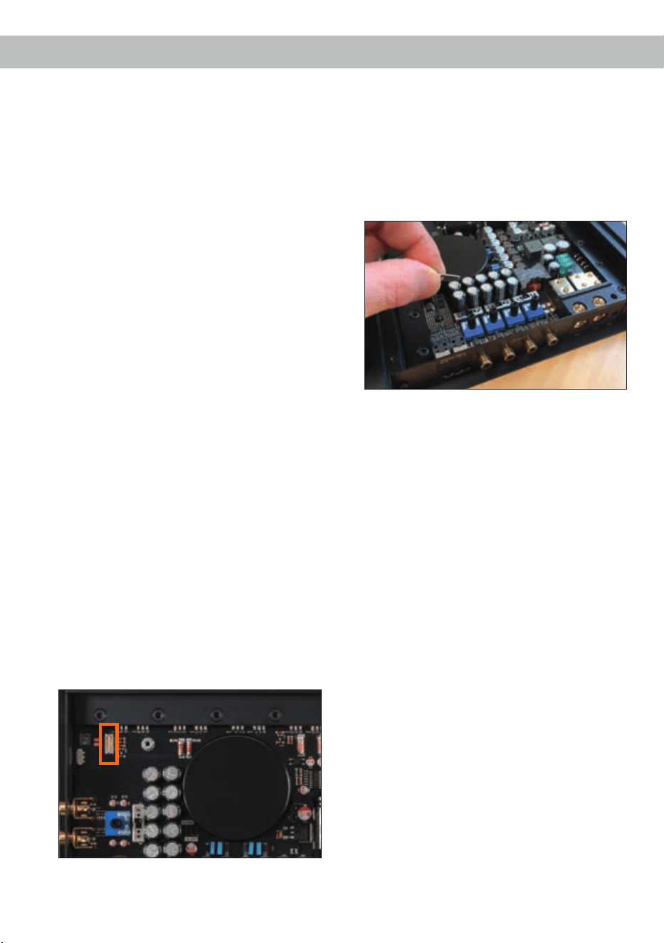
5. Stecken Sie das HDM 1 in den im Gerät vor-
gesehenen Sockel (siehe Markierung im nach-
folgenden Bild). Achten Sie dabei auf den rich-
tigen Sitz des Moduls.
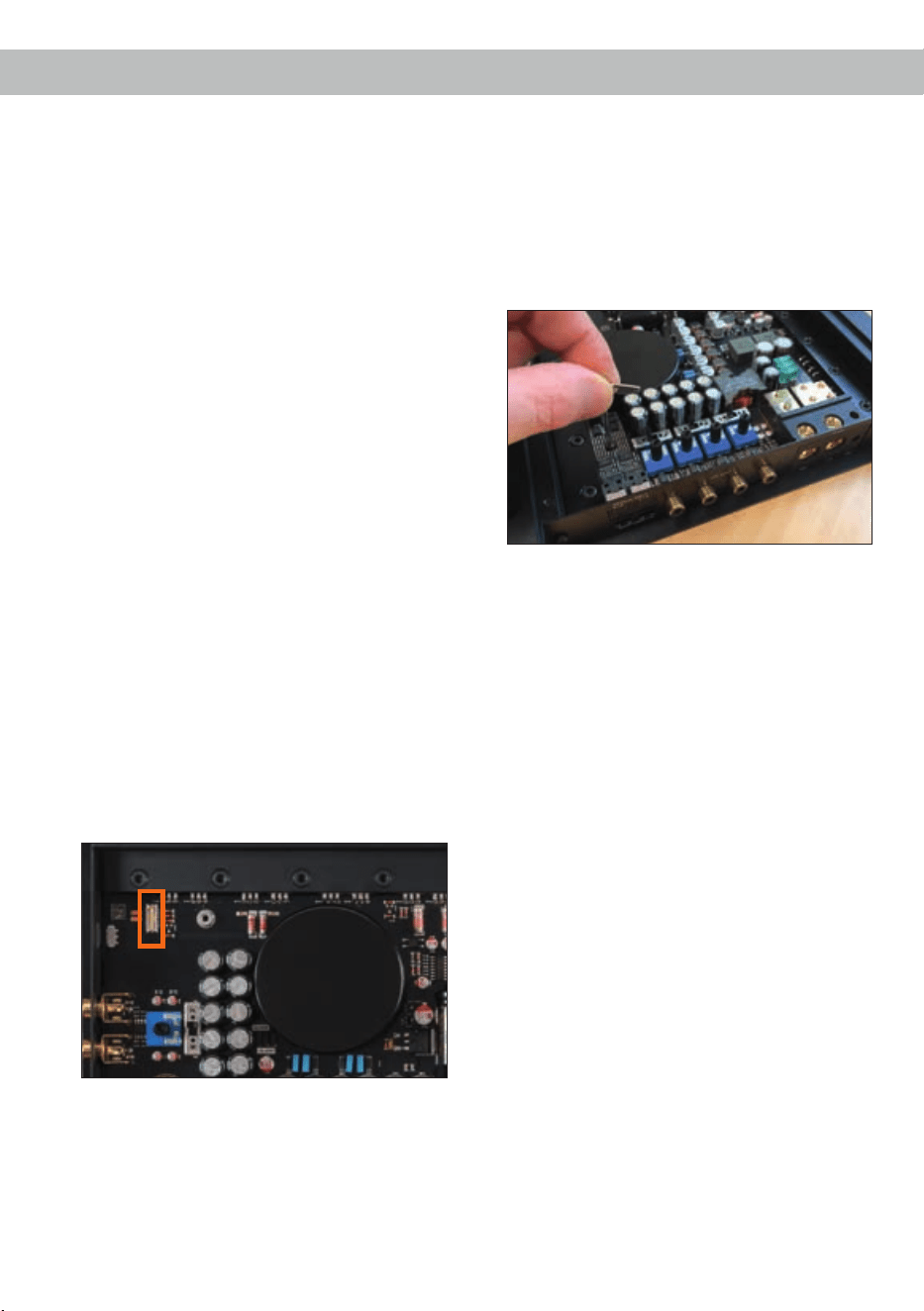
6. Stecken Sie die mitgelieferte Inbusschraube
in die vorgesehen Befestigungsönung des
HDM 1 Moduls und xieren Sie diese sorgfältig.
Achtung: Ziehen Sie die Schraube nicht zu
fest an, da dies das Modul beschädigen kann!
Die nachfolgende Abbildung zeigt beispielhaft
die Fixierung des HDM Moduls anhand eines
HDM 2 im C FOUR Verstärker.
7. Befestigen Sie das neue, dem HDM 1 beilie-
gende Seitenblech mit den Inbusschrauben. Im
Anschluss montieren Sie wieder die Acrylabde-
ckung.
8. Schließen Sie alle Verbindungen wieder an das
Gerät an.
9. Schalten Sie den Verstärker ein. Das installierte
HDM 1 Modul wird automatisch vom Gerät er-
kannt. Weitere Informationen über das Modul
sowie der SPDIF Direct In-Funktion nden Sie
in der Bedienungsanleitung des HDM 1.

15
Leistung RMS / Max. Normalbetrieb TwinPower Link
(Ein Verstärker) (Zwei Verstärker)
- @ 4 Ohm .................................................................. 1 x 525 / 1.050 Watt 1 x 1.660 / 3.320 Watt
- @ 2 Ohm .................................................................. 1 x 830 / 1.660 Watt 1 x 2.200 / 4.400 Watt
- @ 1 Ohm .................................................................. 1 x 1.100 / 2.200 Watt –
Verstärkertechnologie ................................................. Class AB
Eingänge .................................................................... 2 x Cinch
1 x Remote In
1 x Fernbedienungseingang
1 x TwinPower Link
Optional via HDM 1 Modul:
1 x Optisch SPDIF-Format (28 - 96 kHz)
Eingangsempndlichkeit ............................................. Cinch 0,5 - 8 Volt
Eingangsimpedanz Cinch ........................................... 7,5 kOhm
Ausgänge ................................................................... 1 x Lautsprecherausgang
Frequenzbereich......................................................... 10 Hz - 80.000 Hz
Bass Boost ................................................................. 0 - 9 dB / 40 Hz - 120 Hz
Hochpass.................................................................... 15 Hz - 4.000 Hz regelbar
Tiefpass ...................................................................... 15 Hz - 4.000 Hz regelbar
Bandpass.................................................................... 15 Hz - 4.000 Hz regelbar
Phase ......................................................................... 0 - 180° regelbar
Flankensteilheit Hoch- / Tiefpass................................ 12 dB/Okt.
Signal- / Rauschabstand ............................................ 120 dB (A-bewertet)
Klirrfaktor (THD) ......................................................... < 0,006 %
Dämpfungsfaktor ........................................................ > 1000
Betriebsspannung....................................................... 9 - 16 Volt (max. 5 Sek. bis hinab zu 6 Volt)
Leerlaufstromaufnahme.............................................. 2.400 mA
Sicherung ................................................................... 3 x 30 A LP-Mini-Stecksicherung
Zusätzliche Features .................................................. Aktive, regelbare Frequenzweiche, Bass Boost,
HDM Slot, Eingangsmodus-Schalter, TwinPower
Link, Start-Stopfähigkeit
Abmessungen (H x B x T) .......................................... 37,1 x 430 x 240 mm
Technische Daten
Die Garantieleistung entspricht der gesetzlichen
Regelung. Von der Garantieleistung ausgeschlos-
sen sind Defekte und Schäden, die durch Überla-
stung oder unsachgemäße Behandlung entstanden
sind. Eine Rücksendung kann nur nach vorheriger
Absprache in der Originalverpackung, einer de-
taillierten Fehlerbeschreibung und einem gültigen
Kaufbeleg erfolgen.
Technische Änderungen und Irrtümer vorbehalten!
Für Schäden am Fahrzeug oder Gerätedefekte, her-
vorgerufen durch Bedienungsfehler des Gerätes,
können wir keine Haftung übernehmen. Dieses
Produkt ist mit einer CE-Kennzeichnung versehen.
Damit ist das Gerät für den Betrieb in Fahrzeugen
innerhalb der Europäischen Union (EU) zertiziert.
Garantiehinweis

16
Dear Customer,
Congratulations on your purchase of this innovative
and high-qual ity HELIX product.
The HELIX C ONE highlights best quality, excellent
manufacturing and state-of-the-art technology.
Thanks to more than 30 years of experience in
research and development of audio products this
amplier generation sets new standards.
We wish you many hours of enjoyment with your
new HELIX amplier.
Yours,
AUDIOTEC FISCHER Team
General installation instructions for HELIX
components
To prevent damage to the unit and possible injury,
read this manual carefully and follow all installation
instructions. This product has been checked for
proper function prior to shipping and is guaranteed
against manufacturing defects.
Before starting your installation, disconnect the
battery’s negative terminal to prevent damage
totheunit,reand/orriskofinjury. For a proper
performance and to ensure full warranty coverage,
we strongly recommend to get this product installed
by an authorized HELIX dealer.
Install your C ONE in a dry location with sucient
air circulation for proper cooling of the equipment.
The amplier should be secured to a solid mounting
surface using proper mounting hardware. Before
mounting, carefully examine the area around and
behind the proposed installation location to ensure
that there are no electrical cables or components,
hydraulic brake lines or any part of the fuel tank lo-
cated behind the mounting surface. Failure to do so
may result in unpredictable damage to these com-
ponents and possible costly repairs to the vehicle.
General instruction for connecting the HELIX
CONEamplier
The HELIX C ONE amplier may only be installed
in vehicles which have a 12 Volts negative terminal
connected to the chassis ground. Any other system
could cause damage to the amplier and the electri-
cal system of the vehicle.
The positive cable from the battery for the complete
system should be provided with a main fuse at a
distance of max. 30 cm from the battery. The val-
ue of the fuse is calculated from the maximum total
current input of the car audio system.
Use only suitable cables with sucient cable
cross-section for the connection of the HELIX
C ONE. The fuses may only be replaced by iden-
tically rated fuses (3 x 30 A) to avoid damage of
theamplier.
Prior to installation, plan the wire routing to avoid
any possible damage to the wire harness. All
cabling should be protected against possible
crushing or pinching hazards. Also avoid routing
cables close to potential noise sources such as
electric motors, high power accessories and other
vehicle harnesses.
Congratulations!
General instructions
17
Connectors and control units
1
Optical Input (optional)
Optical input for digital stereo signals ( SPDIF
format).
2
SPDIF Direct In switch (optional)
Switch for routing the digital input signal
directly to the ampliers internal power stage.
3
Line Input
RCA inputs for connecting lowlevel line
signals.
4
GND
Connector for the ground cable (negative
terminal of the battery or metal body of the
vehicle).
5
+12 V
Connector for the +12 V power cable of the
positive terminal of the battery.
6
REM
Connector for the remote cable.
7
TwinPower Link switch
Switch for operating two C ONE ampliers in
bridge mode.
8
Mono RCA/Cinch In- / Output
Mono RCA/Cinch signal in- or output for
bridge mode operation in TwinPower Link
mode.
9
Remote Control
Input for connecting the optionally available
cable remote control for volume adjustment.
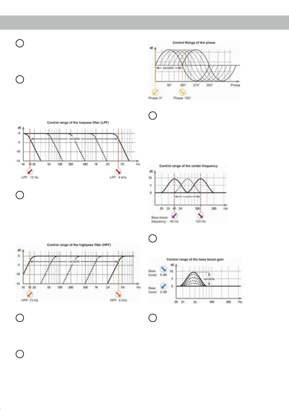
10
LPF
Control for adjusting the lowpass lter of the
from 15 Hz to 4,000 Hz.
11
HPF
Control for adjusting the highpass lter from
15 Hz to 4,000 Hz.
12
Output Channel
Speaker outputs for connecting loudspeak-
ers.
13
Phase
Control for adjusting the phase from 0° to
180°.
14
Bass Boost Frequency
Control for adjusting the center frequency of
the Bass Boost from 40 to 120 Hz.
15
Bass Boost Gain
Control for adjusting the bass boost from 0 to
9 dB.
8 9 127 10 11
1 4 5 6
C ONE side view with optionally available HELIX Digital Input Module HDM 1
3
1513 14
2
optional
18
16
Level control
Control for adjusting the input sensitivity of
the lowlevel Line Inputs.
17
Input Mode switch (stereo / mono)
Switch to adapt the amplier to the number of
used input channels.
18
Power & Protect LED
This LED indicates the operating mode of the
amplier.
19
Fuses
Input fuses for protection against internal
errors.
20
Impedance selection switch
Switch for adapting the amplier to the im-
pedance of the connected speaker.
21
LED switch
Switch for turning on and o the LED illumi-
nation.
22
CutoFrequencyswitch
Switch for adjusting the maximum upper cut-
o frequency of the appropriate crossover
lter.
23
X-Over switch
Switch for activating the lters for each
channel pair.
24
HDM Slot
Slot for the optionally available HELIX Digital
Input Module HDM 1.
16
19
17
20
18
22
22
21
24
23
Connectors and control units
19
Initial start-up and functions
1
Optical Input (optional)
Optical input in SPDIF format for connecting signal
sources with a digital audio output. The sampling
rate of this input must be between 28 and 96 kHz.
Please note: The digital input is not part of the
C ONEs standard equipment. This can only be ret-
rotted with the optionally available HELIX Digital
Input Module HDM 1.
Important: The signal of a digital audio source nor-
mally does not contain any information about the
volume level. Keep in mind that this will lead to full
level on the outputs of the HELIX C ONE. This may
cause severe damage to your speakers. We strong-
ly recommend to only use volume controlled audio
sources!
Note: This amplier can only handle stereo input
signals and no MP3- or Dolby-coded digital audio
stream!
Note: It is possible to use the Optical Input and the
lowlevel Line Input at the same time.
2
SPDIF Direct In switch (optional)
Due to the SPDIF Direct In switch, the input stages
of the C ONE can be bypassed and the input sig-
nal of the Optical Input directly and losslessly rout-
ed from the integrated DA converter to the internal
power stage. To activate the direct signal routing
you have to set the SPDIF Direct In switch to “On”.
Please note: The SPDIF Direct In function is not
part of the C ONEs standard equipment. It is solely
included in the optionally available HELIX Digital In-
put Module HDM 1.
Note: This switch only aects the signal routing of
the Optical Input.
Note: The amplier must be operated in fullrange
mode for routing the digital input signal directly to
the power stage. Therefore change the position of
the X-Over switch to “FULL“ (see page 21, item 23).
Note: If the switch is set to “On” position the lowlev-
el Line Input (3) as well as the Level control (16) are
without function!
3
Line Input
2-channel lowlevel line input to connect signal
sourc es such as head units / radios / DSPs.
4
GND
The ground cable should be connected to a common
ground reference point (this is located where the
negative terminal of the battery is grounded to the
metal body of the vehicle) or to a prepared metal lo-
cation on the vehicle chassis i.e. an area which has
been cleaned of all paint residues. Recommended
cross section: min. 16 mm² / AWG 6.
5
+12 V
Connect the +12 V power cable to the positive ter-
minal of the battery. Recommended cross section:
min. 16 mm² / AWG 6.
6
REM
The remote lead should be connected to the remote
output / automatic antenna (aerial positive) output
of the head unit / car radio. This is only activated
if the head unit / car radio is switched on. Thus the
amplier is switched on and o together with the
head unit / car radio. As soon as there is an addi-
tional digital signal processor (DSP) implemented in
the signal path, the remote output of the DSP has to
be used to turn on the C ONE.
7
TwinPower Link switch
The HELIX C ONE amplier can be connected to
a second C NE via the TwinPower Link by which
the output power is more than doubled, depending
on the speaker conguration. In order to operate
two ampliers in this mode, they must be connect-
ed with a RCA / Cinch cable (see page 19, item 8;
Mono RCA/Cinch In- / Output). The amplier which
is set as “Master” assumes the complete control
(active crossover, bass boost etc.) for both amps.
All lter adjustments of the amplier which operates
in “Slave” mode will be deactivated.
Attention: Make sure that one amplier is adjusted
as “Master” and the other one as “Slave”. In this
mode the minimum speaker impedance is 2 Ohms.
Note: If the amplier operates individually the Twin-
Power Link switch must be set to “Master”.
Examples for speaker congurations in TwinPower
Link mode can be found on page 26.
8
Mono RCA/Cinch In- / Output
This connector serves as signal in- or -output for
connecting a further C ONE amplier in bridge
mode (see page 19, item 7; TwinPower Link switch).
20
9
Remote Control
This input is used to connect an optionally available
remote control. The remote control allows you to
control the volume of the amplier.
10
LPF
This control is used to ne tune the crossover fre-
quency of the lowpass lter from 15 Hz to 4,000 Hz.
Always use the respective Cuto Frequency switch
rst to adjust the lter (see page 21, item 22; Cuto
Frequency switch).
11
HPF
This control is used to ne tune the crossover
frequency of the highpass lter from 15 Hz to
4,000 Hz.
Always use the respective Cuto Frequency switch
rst to adjust the lter (see page 21, item 22; Cuto
Frequency switch).
12
Output Channel
Speaker outputs to connect loudspeakers. The
impedance per channel must not be lower than
1 Ohm.
13
Phase
This control is used to adjust the phase from 0° to
180°. This allows to match the phase of the sub-
woofer with the other speakers thus avoiding any
cancellations in the frequency response due to
phase shifts.
14
Bass Boost Frequency
This control is used to adjust the center frequency
of the Bass Boost from 40 Hz to 120 Hz. The adjust-
ed bass frequency can be enhanced from 0 to 9 dB
with control 15.
This is useful to emphasize or correct a determined
frequency of the subwoofer (kickbass).
15
Bass Boost Gain
This control is used to increase the adjusted Bass
Boost Frequency (see item 14) from 0 to 9 dB.
16
Level control
This control is used to adapt the input sensitivity to
the output voltage of the connected signal source.
This is not a volume control, it´s only for adjusting
the amplier gain. The control range is 0.5 - 8 Volts.
The setting of the control also aects the digital
signal input of the optionally available HDM 1 mod-
ule if the SPDIF Direct In switch is not set to “On”
position.
Initial start-up and functions

21
17
Input Mode switch (stereo / mono)
This switch is used to adapt the amplier to the
number of used inputs.
Stereo: Select this switch setting if both input chan-
nels (A and B) are used. In this mode an optimized
sum signal is generated by the input signals of the
channels A and B.
Mono: In mono operation only input channel A
needs to be connected e.g. the signal source only
provides a mono signal for subwoofer applications.
18
Power & Protect LED
The power and protect LED indicates the operating
mode of the amplier.
Green: The amplier is ready for operation.
Yellow: The amplier is overheated. The internal
temperature protection shuts down the device until
it reaches a safe temperature level again.
Flashing yellow: The fuses inside the device are
blown. Please check the fuses and, if necessary,
replace them. They may only be replaced by identi-
cally rated fuses (3 x 30 Ampere) to avoid damage
of the amplier.
Red: A malfunction has occurred that may have dif-
ferent root causes. The HELIX C ONE is equipped
with protection circuits against over- and undervolt-
age, short-circuit on loudspeakers and reverse con-
nection. Please check for connecting failures such
as short-circuits or other wrong connections. If the
amplier does not turn on after that it is defective
and has to be sent to your local authorized dealer
for repair service.
19
Fuses
The input fuses are connected in parallel and pro-
vide protection against an internal fault of the de-
vice, therefore the system must be additionally pro-
tected by a further main fuse located close to the
battery (max. distance from battery: 30 cm / 12”).
The HELIX C ONE is equipped with 3 x 30 Ampere
fuses.
20
Impedance selection switch
By using the impedance selection switch the im-
pedance of the connected loudspeakers (4 Ohms,
2 Ohms or 1 Ohm) has to be selected accordingly.
If several loudspeakers are connected, the imped-
ance can be approximately calculated as follows:
Series connection: Z total = Z x n
Parallel connection: Z total = Z / n
(n = amount of loudspeakers; Z = loudspeaker im-
pedance)
Note: If speakers with “3 Ohms” impedance are
used, please choose the position “4 Ohms”.
Important: In TwinPower Link operation both am-
pliers must have the same impedance setting (see
page 19, item 7; TwinPower Link switch).
21
LED switch
This switch is used to turn on and o the extended
LED illumination of the amplier. It has no eect on
the LEDs below the fan, which are used as ultra
low-noise current sources in the output driver stag-
es. The functionality of the Power & Protect LED
remains unaected as well.
Note: The number of illuminated LEDs depends on
the settings made on the amplier – e.g. MONO or
STEREO mode.
22
CutoFrequencyswitch
These switches are used to adjust the maximum
upper cuto frequency of the highpass (HPF) and
lowpass (LPF) lter. Afterwards a ne tuning can be
done with control 10 (LPF) and 11 (HPF).
23
X-Over switch
This switch allows to set the internal crossover to
highpass, fullrange or bandpass mode.
If the X-Over switch is set to HPF the crossover fre-
quency for the highpass can be adjusted with the
respective Cuto Frequency switch (22) and control
(11 / HPF).
At switch position FULL (fullrange) the crossover is
bypassed.
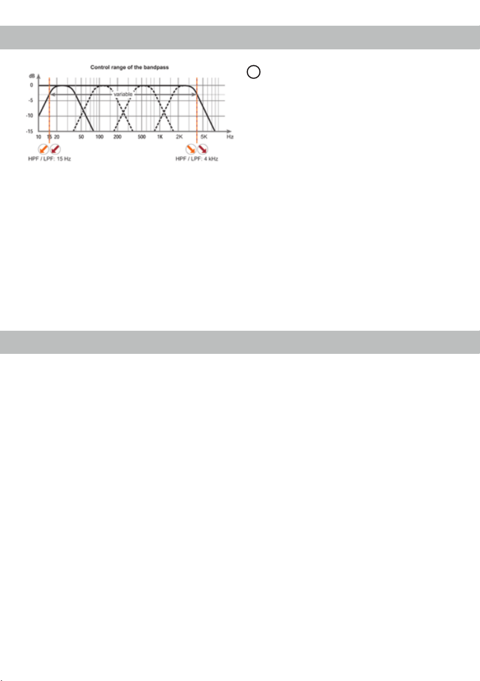
At switch position BPF a bandpass is created in
any case. This means that the highpass is always
active. By adjusting the highpass (switch 22 and
control 11 / HPF) and lowpass (switch 22 and con-
trol 8 / LPF) lter any bandpass between 15 Hz and
4,000 Hz can be realized.
22
Caution: To avoid a loss of gain make sure that the
crossover frequencies of the high- and lowpass l-
ters do have an interval of at least two octaves
when generating a bandpass.
That means if the lowpass signal is adjusted to
320 Hz the highpass should be adjusted to 80 Hz
or less (one octave = doubled frequency or halved
frequency). If a subwoofer is connected we recom-
mend to use the highpass control (control 11 / HPF)
as variable subsonic / low-frequency highpass lter
or turn it counterclockwise to 15 Hz to get a sub-
sonic lter.
24
HDM slot
The HDM slot is used to mount the optionally avail-
able HELIX Digital Input Module HDM 1.
The module extends the amplier with an optical
digital input in SPDIF format including SPDIF Direct
In switch.
Thanks to the SPDIF Direct In switch the input stag-
es of the C ONE can be bypassed and allows to
directly route the signals of the digital input from the
integrated DA converter to the internal power stage.
Further information about the module can be found
on page 27.
Connection of HELIX C ONE to the head unit /
car radio:
Caution: Carrying out the following steps will re-
quire special tools and technical knowledge. In or-
der to avoid connection mistakes and / or damage,
ask your dealer for assistance if you have any ques-
tions and follow all instructions in this manual (see
page 16). It is recommended that this unit will be
installed by an authorized HELIX dealer.
1. Connecting the lowlevel line inputs
Use the correct cable (RCA / Cinch cable) to
connect these inputs to the lowlevel line outputs
of your head unit / car radio. It is not mandato-
ry to use both lowlevel line inputs. If only one
channel will be connected use channel A and
set the Input Mode switch to “MONO”.
When both channels will be used please choose
switch position “STEREO” (see page 21,
item 17; Input Mode switch).
2. Connecting a digital signal source
If you have installed the HELIX Digital Input
Module HDM 1 and have a signal source with
an optical digital output you can connect it di-
rectly to the amplier using the appropriate in-
put.
Important: The signal of a digital audio source
normally does not contain any information
about the volume level. Keep in mind that this
will lead to full level on the outputs of the HELIX
C ONE. This may cause severe damage to your
speakers. We strongly recommend to only use
volume controlled audio sources!
Information: The C ONE can only handle un-
compressed digital stereo signals in PCM for-
mat with a sample rate between 28 kHz and
96 kHz and no MP3- or Dolby-coded signals.
3. Congurationofthedigitalsignalinput
If you have installed the HELIX Digital Input
Module HDM 1 and connected a digital signal
source you have the possibility to route the dig-
ital signal directly and loss-free from the inte-
grated DA converter to the internal power am-
plier. To activate the direct signal routing you
have to change the position of the SPDIF Direct
Initial start-up and functions
Installation

23
In switch to “On” (see page 19, item 2) as well
as the position of the X-Over switch to “FULL”
(see page 21, item 23).
Note: This switch only aects the signal routing
of the optical input.
4. Adjustmentoftheinputsensitivity
Attention: It is mandatory to properly adapt
the input sensitivity of the C ONE to the sig-
nal source in order to avoid damage to the
amplier.
If you want to change the input sensitivity use
the Level control (see page 20, item 16; Level
control).
5. Connection to power supply
Make sure to disconnect the battery before
installing the HELIX C ONE!
Connect the +12 V power cable to the positive
terminal of the battery. The positive wire from
the battery to the amplier power terminals
needs to have an inline fuse at a distance of
less than 12 inches (30 cm) from the battery.
The value of the fuse is calculated from the
maximum total current draw of the whole car
audio system (C ONE = max. 90 A RMS at
12 V power supply). If your power wires are
short (less than 1 m / 40”) then a wire gauge
of 16 mm² / AWG 6 will be sucient. In all other
cases we strongly recommend gauges of 25 -
35 mm² / AWG 4 – 2!
The ground cable (same gauge as the +12 V
wire) should be connected to a common ground
reference point (this is located where the neg-
ative terminal of the battery is grounded to the
metal body of the vehicle), or to a prepared met-
al location on the vehicle chassis, i.e. an area
which has been cleaned of all paint residues.
6. Connecting the remote input
The remote input (REM) has to be connected to
the radio remote output. This is only activated
if the head unit / car radio is switched on. Thus
the amplier is switched on and o together with
the head unit / car radio.
We do not recommend controlling the remote
input via the ignition switch to avoid pop noise
during turn on / o.
If an additional digital signal processor (DSP)
is installed in the signal path between the radio
and the amplier, the remote output of the DSP
must be used to turn on the C ONE.
7. Connecting the loudspeaker outputs
The loudspeaker outputs can be connected
directly to the wires of the loudspeakers. Never
connect any of the loudspeaker cables to the
chassis ground as this will damage your ampli-
er and your speakers.
Ensure that the loudspeakers are identical and
corrctly connected (in phase), i.e. plus to plus
and minus to minus. Exchanging plus and mi-
nus causes a total loss of bass reproduction.
The positive terminal is indicated on most
speakers. The impedance must not be less
than 1 Ohm (2 Ohms in TwinPower Link mode),
otherwise the amplier protection will be acti-
vated. Examples for speaker congurations can
be found on page 24 et sqq.
Start-Stop capability
The switched power supply of the HELIX C ONE
assures operation even if the battery’s voltage
drops down to 6 Volts during engine crank.
High-Resolution audio
The extremely broadband audio bandwidth of the
amplier ensures a lossless audio reproduction of
High-Resolution audio content to provide the best
possible sound in studio quality.
Unique Features of the HELIX C ONE

24
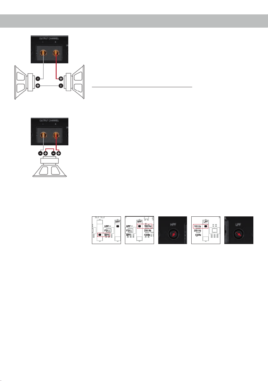
Examplesforspeakercongurations
Mono subwoofer application
Subwoofer with one voice coil (single voice coil)
Maximum output power of this conguration:
1 x 4 Ohms: 525 / 1,050 Watts
1 x 2 Ohms: 830 / 1,660 Watts
1 x 1 Ohm: 1,100 / 2,200 Watts
Two subwoofers with
a single voice coil
One subwoofer with
a dual voice coil
Filter settings
Bandpass, high- and lowpass lter
Highpass lter
ca. 15 Hz
Bandpass
(BPF)
Highpass lter
100 Hz
Lowpass lter
100 Hz
Lowpass lter
ca. 80 Hz
Parallel operation
Two identical subwoofers with one voice coil (single voice coil) or one
subwoofer with dual voice coil are connected in parallel.
Note: The parallel connection of two voice coils will result in halving the
impedance!
Maximum output power of this conguration:
Two subwoofers with 1 x 4 Ohms correspond to a total impedance of
2 Ohms: 830 / 1,660 Watts
One subwoofer with 2 x 4 Ohms also corresponds to a total impedance
of 2 Ohms: 830 / 1,660 Watts
Two subwoofers with 1 x 2 Ohms correspond to a total impedance of
1 Ohm: 1,100 / 2,200 Watts
One subwoofer with 2 x 2 Ohms also corresponds to a total impedance
of 1 Ohm: 1,100 / 2,200 Watts
Note: The parallel connection of 1 Ohm voice coils will result in shut-
down of the amplier.
Filter settings
Bandpass, high- and lowpass lter
Highpass lter
ca. 15 Hz
Bandpass
(BPF)
Highpass lter
100 Hz
Lowpass lter
100 Hz
Lowpass lter
ca. 80 Hz
Note: The values listed here are empirical values that have been approved as useful in practice.
25
In series
Two identical subwoofers with one voice coil (single voice coil) or one
subwoofer with dual voice coil are connected in series.
Note: The connection of two voice coils in series will result in doubling
the impedance!
Maximum output power of this conguration:
Two subwoofers with 1 x 2 Ohms correspond to a total impedance of
4 Ohms: 525 / 1,050 Watts
One subwoofer with 2 x 2 Ohms also corresponds to a total impedance
of 4 Ohms: 525 / 1,050 Watts
Two subwoofers with 1 x 1 Ohm correspond to a total impedance of
2 Ohms: 830 / 1,660 Watts
One subwoofer with 2 x 1 Ohm also corresponds to a total impedance of
2 Ohms: 830 / 1,660 Watts
Note: The connection of subwoofers with 4 Ohms in series is not recom-
mended because it results in a low output power of the amplier!
Filter settings
Bandpass, high- and lowpass lter
Highpass lter
ca. 15 Hz
Bandpass
(BPF)
Highpass lter
100 Hz
Lowpass lter
100 Hz
Lowpass lter
ca. 80 Hz
Two subwoofers with
a single voice coil
One subwoofer with
a dual voice coil
Note: The values listed here are empirical values that have been approved as useful in practice.
26
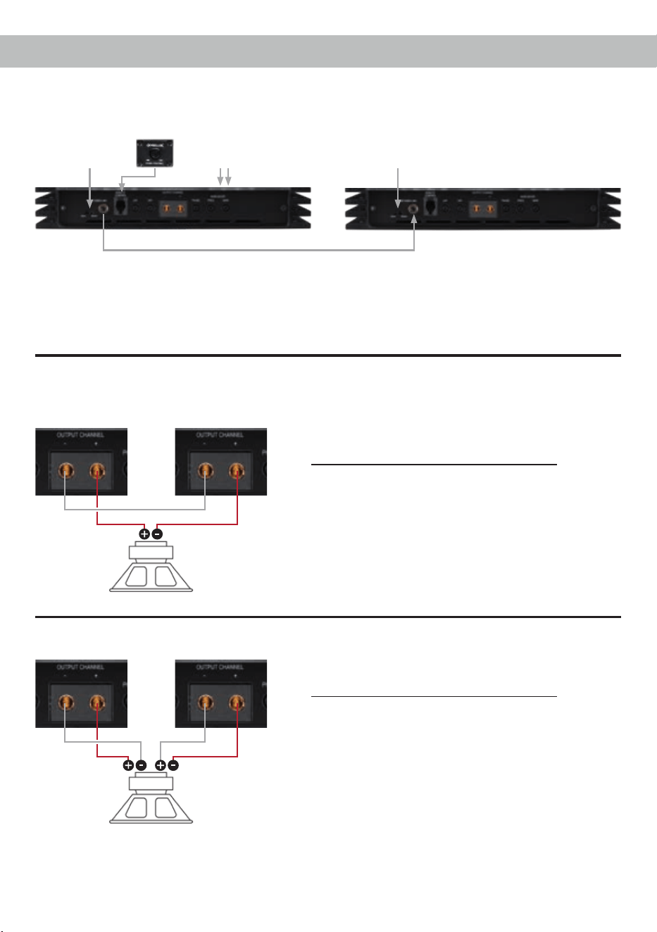
ExamplecongurationsforTwinPowerLinkoperation
Master Slave
AmplierconnectioninTwinPowerLinkoperation
RCA/Cinch signal
from the radio
RCA/Cinch cable
Master Slave
One subwoofer with dual voice coil
(dual voice coil)
Maximum output power of this conguration:
2 x 4 Ohms: 1,050 / 2,100 Watts
2 x 2 Ohms: 1,660 / 3,320 Watts
2 x 1 Ohms: 2,200 / 4,400 Watts
Note: In this conguration example an 1 Ohm congu-
ration in TwinPower Link operation is possible but not
advisable!
Attention: The second voice coil of the
subwoofer must be connected in re-
versed polarity to the amplier which
isadjustedas“Slave”!
Switch setting:
Master
Switch setting:
Slave
Speaker connection in TwinPower Link operation
Master Slave
One subwoofer with one voice coil
(single voice coil)
Maximum output power of this conguration:
1 x 4 Ohms: 1,660 / 3,320 Watts
1 x 2 Ohms: 2,200 / 4,400 Watts
Note: The negative terminals of both ampliers have to
be connected by using a speaker wire. The size should
be similar to the speaker wires which are used for the
subwoofer connection.
*
Important: Both ampliers must be set to the same impedance (see page 21, item 20; Impedance selection
switch). The lter settings (HPF, LPF, bass boost etc.) are assumed by the master amplier. All controls of
the slave amplier are deactivated.
* Optional accessory. The remote control is not part of the C ONEs standard equipment.
27
Installation of the HELIX Digital Input Module HDM 1
It is possible to extend the HELIX C ONE ampli-
er with an optical digital input in SPDIF format incl.
SPDIF Direct In switch by mounting the HELIX Dig-
ital Input Module HDM 1.
To install the module it is necessary to remove the
side panel of the C ONE and replace it by the new
side panel that comes with the HDM 1.
Attention: Install the HDM 1 only in the designat-
eddeviceanditsspecicslot.Usingthemodule
in other devices or slots can result in damage of
theHDM1module,theamplier,theheadunit/
car radio or other connected devices!
Read in the following the steps how to install the
module:
1. First disconnect the power supply (+12 V /
GND / REM) and RCA / Cinch cables from the
device.
2. Remove the acrylic cover by loosening the eight
Allen screws.
3. Then dismantle the side panel where the pow-
er supply is located by removing the two Allen
screws.
4. Prepare the module for installing it into the de-
vice. Any further mounting information will be
found in the instruction manual of the HDM 1.
5. Insert the module into the specic slot of the
device which is marked in the following picture.
Make sure that the module is installed properly.
6. Insert the Allen screw which is delivered with
the HDM 1 into the mounting hole of the module
and x it carefully.
Caution: Do not overtighten the screw as this
may damage the module.
The following gure shows the xation of a
HDM module in the amplier using the example
of the HELIX C FOUR.
7. Fix the new side panel which is delivered with
the HDM 1 module with the Allen screws. After-
wards remount the acrylic cover, too.
8. Reconnect all connections to the device.
9. Turn on the amplier. The digital inputs are
automatically detected by the device. Further
information about the module as well as the
SPDIF Direct In function can be found in the
instruction manual of the HDM 1 module.

Audiotec Fischer GmbH
Hünegräben 26 · 57392 Schmallenberg · Germany
Tel.: +49 2972 9788 0 · Fax: +49 2972 9788 88
E-mail: helix@audiotec-scher.com · Internet: www.audiotec-scher.com
The limited warranty comply with legal regulations.
Failures or damages caused by overload or im-
proper use are not covered by the warranty. Please
return the defective product only with a valid proof
of purchase and a detailed malfunction description.
Technical specications are subject to change!
Errors are reserved! For damages on the vehicle
and the device, caused by handling errors of the
device, we can’t assume liability. This product is
tagged with a CE-Certikation mark. Thereby these
devices are certied for the use in vehicles within
the European Community (EC).
Technical Data
Warranty Disclaimer
Output power RMS / max. Normal operation TwinPower Link
(One amplier) (Two ampliers)
- @ 4 Ohms ................................................................ 1 x 525 / 1,050 Watts 1 x 1,660 / 3,320 Watts
- @ 2 Ohms ................................................................ 1 x 830 / 1,660 Watts 1 x 2,200 / 4,400 Watts
- @ 1 Ohm .................................................................. 1 x 1,100 / 2,200 Watts –
Amplier technology ................................................... Class AB
Inputs .......................................................................... 2 x RCA / Cinch
1 x Remote In
1 x Remote control input
1 x TwinPower Link
Optional via HDM 1 module:
1 x Optical SPDIF (28 - 96 kHz)
Input sensitivity ........................................................... RCA / Cinch 0.5 - 8 Volts
Input impedance RCA / Cinch .................................... 7.5 kOhms
Outputs ....................................................................... 1 x Speaker output
Frequency response ................................................... 10 Hz - 80,000 Hz
Bass boost .................................................................. 0 - 9 dB / 40 Hz - 120 Hz
Highpass..................................................................... 15 Hz - 4,000 Hz adjustable
Lowpass ..................................................................... 15 Hz - 4,000 Hz adjustable
Bandpass.................................................................... 15 Hz - 4,000 Hz adjustable
Phase ......................................................................... 0 - 180° adjustable
Slope high- / lowpass ................................................. 12 dB/Oct.
Signal-to-noise ratio.................................................... 120 dB (A-weighted)
Distortion (THD) .......................................................... < 0.006 %
Damping factor ........................................................... > 1000
Operating voltage ....................................................... 9 - 16 Volts (max. 5 sec. down to 6 Volts)
Idle current.................................................................. 2,400 mA
Fuse............................................................................ 3 x 30 A LP-Mini-fuse (APS)
Additional features ...................................................... Active, adjustable crossover, bass boost, HDM
slot, input mode switch, TwinPower Link, Start-Stop
capability
Dimensions (H x W x D) ............................................. 37.1 x 430 x 240 mm / 1.46 x 16.93 x 9.45”