

OPERATOR'S MANUAL
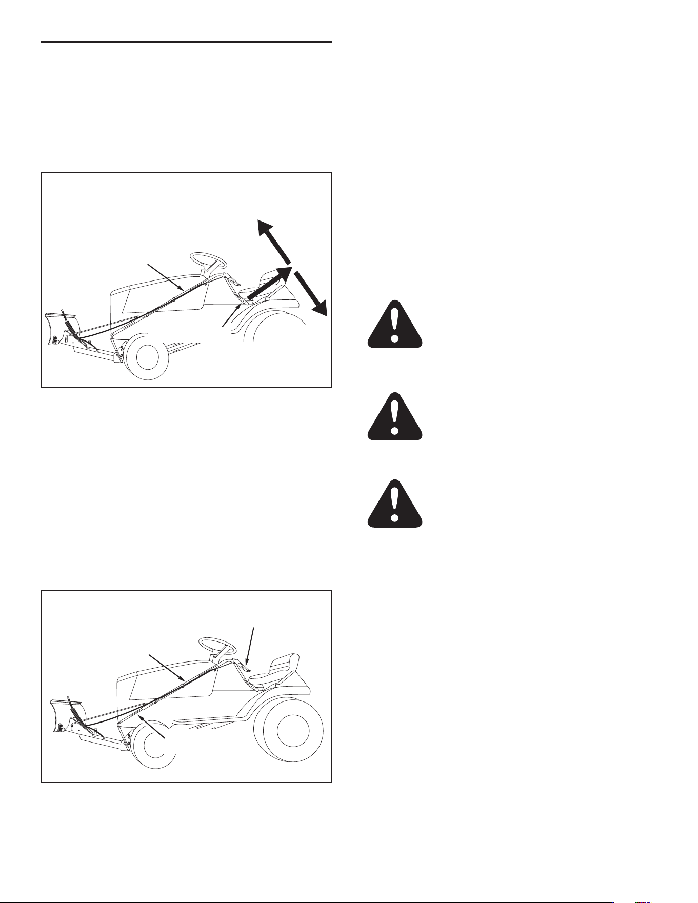
IMPORTANT: READ SAFETY RULES AND INSTRUCTIONS CAREFULLY
PRINTED IN U.S.A. FORM NO. 28052 (03/03/25)
48" SNOW BLADE
Model Number
45-04292-669
Husqvarna
546 07 98-01
2
1. Read the tractor and snow blade owner's manuals and know how to operate your tractor before using tractor with snow
blade attachment.
2. Never operate tractor and snow blade without wearing proper clothing suited to weather conditions and operation of
controls.
3. Never allow children to operate tractor and snow blade, and do not allow adults to operate without proper instructions.
4. Always begin with transmission in rst (low) gear and gradually increase speed as required.
SAFETY RULES
Remember, any power equipment can cause injury if operated improperly or if the user does not understand how to operate
the equipment. Exercise caution at all times when using power equipment.
LOOK FOR THIS SYMBOL TO POINT OUT
IMPORTANT SAFETY PRECAUTIONS. IT
MEANS — ATTENTION! BECOME ALERT!
YOUR SAFETY IS INVOLVED.
CAUTION: VEHICLE BRAKING AND
STABILITY MAY BE AFFECTED WITH THE
ADDITION OF AN ACCESSORY OR AN
ATTACHMENT. BE AWARE OF CHANGING
CONDITIONS ON SLOPES.
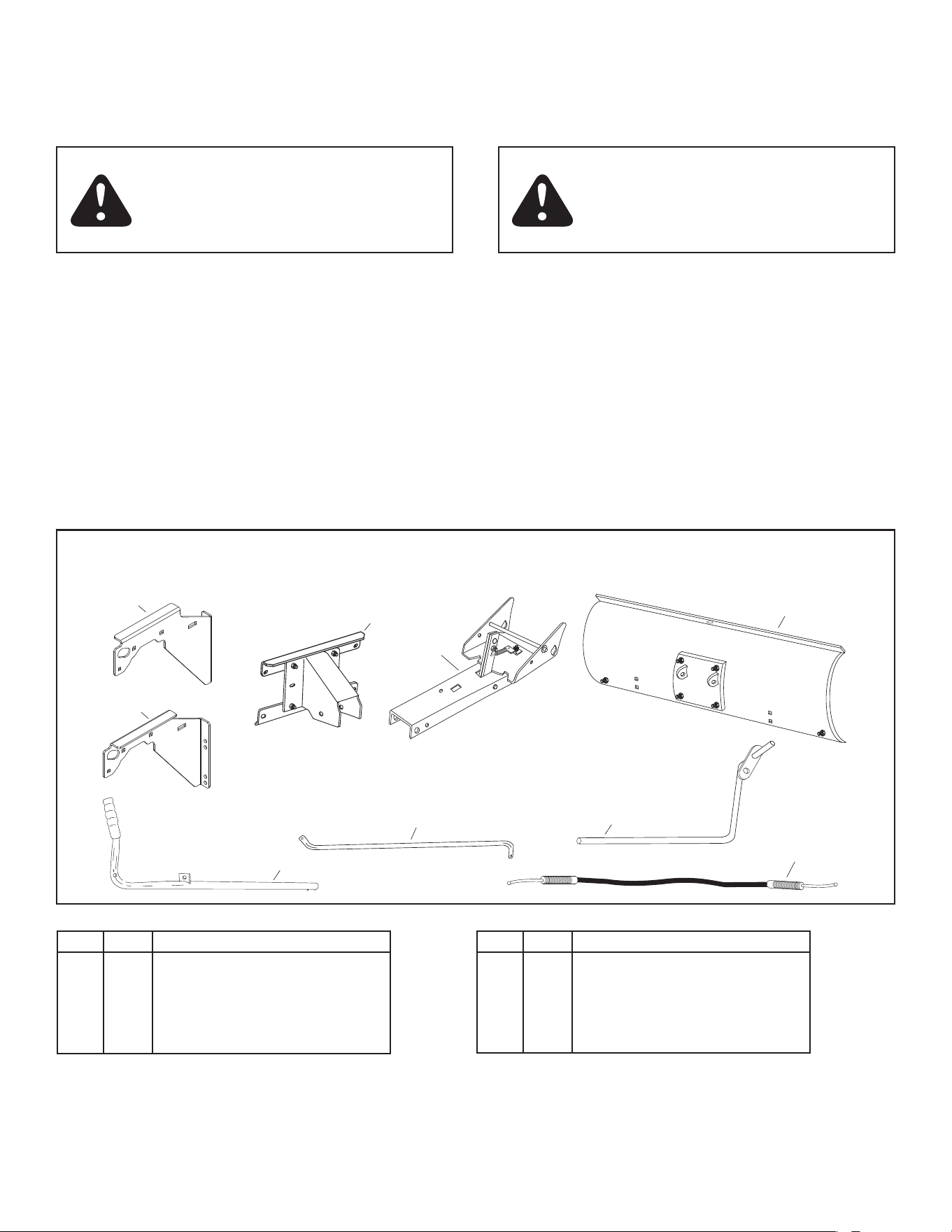
CARTON CONTENTS (Loose Parts in Carton)
6
9
7
2
1
3
4
5
8
REF QTY DESCRIPTION
1 1 Hanger Bracket, L.H.
2 1 Hanger Bracket, R.H.
3 1 Pivot Support Assembly
4 1 Channel Assembly
5 1 Blade Assembly
REF QTY DESCRIPTION
6 1 Blade Pivot Rod
7 1 Lift Handle Tube W/Grip
8 1 Lift Handle Rod
9 1 Cable
3
D
K
H
I
J
G
B
Q
E
C
M
P
N
O
L
F
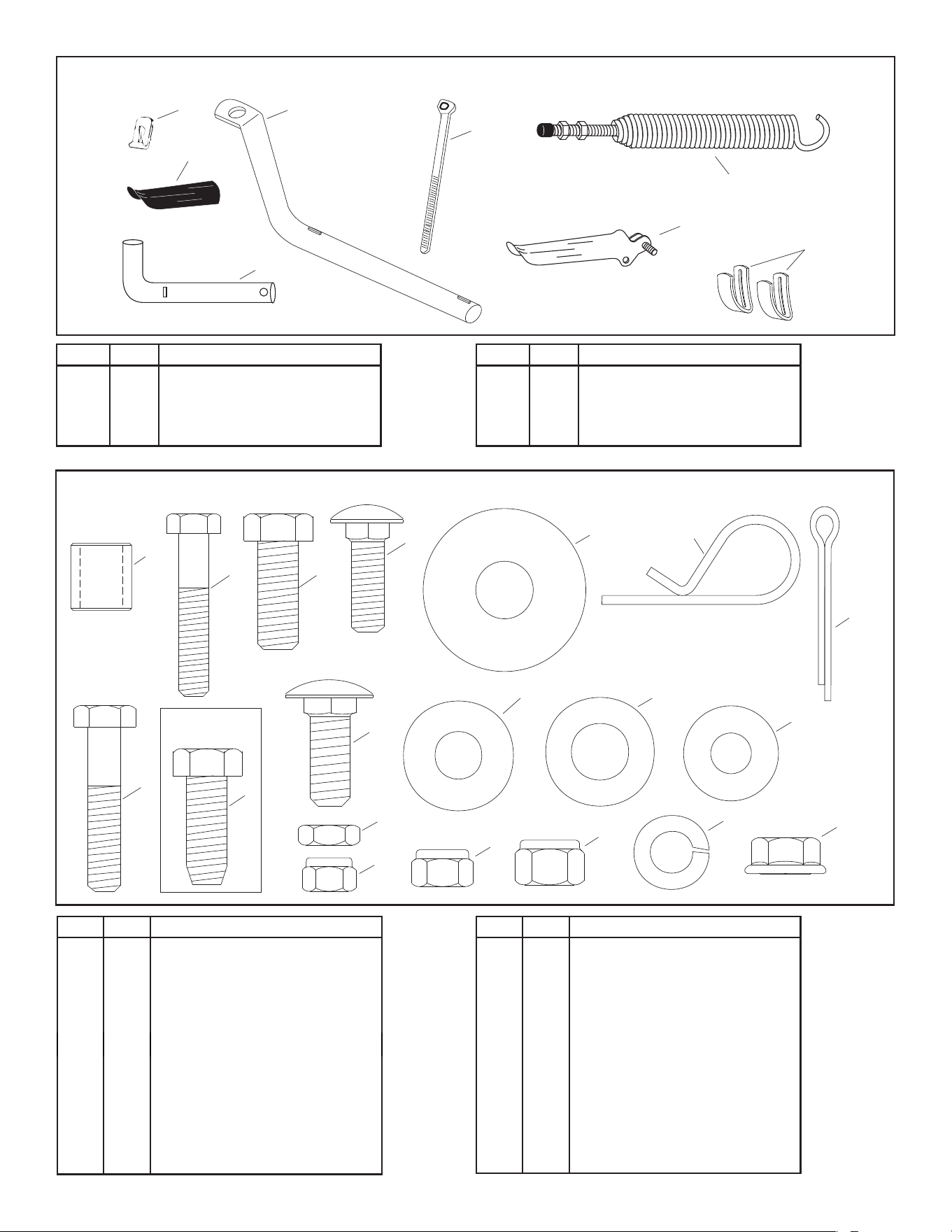
SPECIAL
USE ONLY
A
R
S
(HARDWARE SHOWN FULL SIZE)
10
12
15
13
14
16
11
17
PARTS IN PACKAGES NOT SHOWN FULL SIZE
REF QTY DESCRIPTION
10 2 Cable End Fitting
11 1 Blade Pivot Shaft
12 2 Nylon Tie
13 1 Blade Adjust Spring
REF QTY DESCRIPTION
14 1 Plastic Grip
15 1 Channel Pivot Pin
16 1 Grip Assembly
17 2 Skid Shoe
REF. QTY. DESCRIPTION
A 1 Spacer, 5/8" Long
B 1 Hex Bolt, 1/4-20 x 1-1/2"
C 1 Hex Bolt, 5/16-18 x 1-1/2"
D 10 Hex Bolt, 3/8-16 x 1"
E 6 Bolt, Carriage 5/16-18 x 1"
F 6 Hex Bolt, 3/8" x 1" Thd. Forming
G 6 Carriage Bolt, 3/8-16 x 1"
H 2 Hex Jam Nut, 5/16" Fine Thd.
I 2 1/4" Nylock Hex Nut
J 7 5/16" Nylock Hex Nut
REF. QTY. DESCRIPTION
K 6 3/8" Nylock Hex Nut
L 6 1/2" Washer, (Large)
M 6 3/8" Washer
N 4 Hairpin Cotter
O 2 Cotter Pin 1/8" x 1-1/4"
P 1 1/2" Washer
Q 6 3/8" Lock Washer
R 4 5/16" Washer
S 4 3/8" Flanged Lock Nut
4
(1) Pliers
(1) Hammer
(1) Adjustable Wrench (or socket set)
(1) 9/16" Open End or Box End Wrench
(1) 7/16" Open End or Box End Wrench
(1) 1/2" Open End or Box End Wrench
TOOLS REQUIRED FOR ASSEMBLY
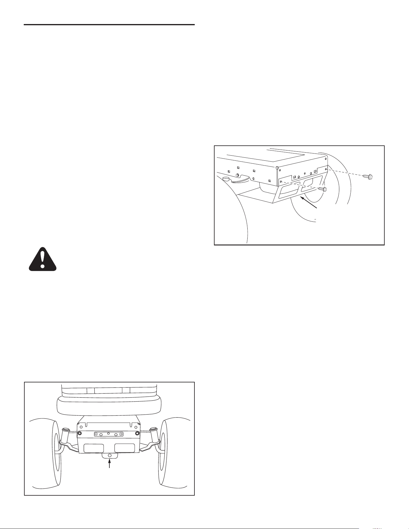
2. Look under the front of your tractor. If there is a single
mower deck suspension bracket located underneath the
middle of the front axle as shown in gure 1, continue
on to step 3. If your tractor does not have a mower deck
suspension bracket underneath the middle of the front
axle, skip to step 7 on page 5 for LT tractors with dual
suspension brackets or step 16 on page 6 for GT tractors
with dual suspension brackets.
MOWER DECK
SUSPENSION
BRACKET
FIGURE 1
1. Remove all parts and hardware packages from the
carton. Lay out parts and hardware and identify using
the illustrations on pages 2 and 3.
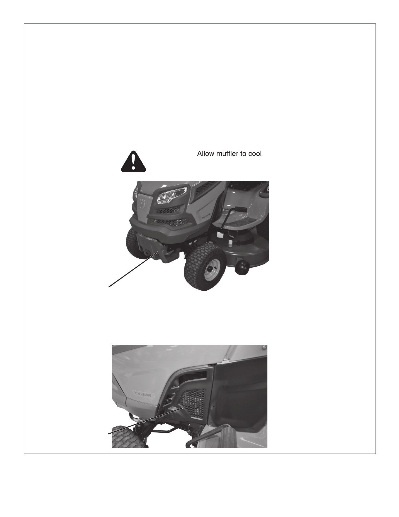
CAUTION: Do not begin assembling until the
tractor engine, muffler and exhaust deector
have been allowed to cool off.
REMOVE
BROWNING
SHIELD
FIGURE 2
3. Remove the tractor hood. Refer to your tractor owners
manual for instructions on how to properly remove the
hood.
4. Remove the browning shield from the front of the tractor
as shown. Hold onto the shield as you remove the second
bolt to prevent it from falling. See gure 2.
NOTE: Reinstall the browning shield before using your tractor.
Please see supplement page 14
SECTION 1:
ASSEMBLY INSTRUCTIONS
NOTE: Not all of the supplied parts and hardware will be
needed for one particular tractor. Unneeded items may be
discarded after assembly has been completed.
NOTE: Right hand (RH) and left hand (LH) are determined
from the operator's position while seated on the tractor.
INSTRUCTIONS FOR ALL TRACTORS
INSTRUCTIONS FOR TRACTORS WITH A
SINGLE SUSPENSION BRACKET
5
FIGURE 4
7. Compare your tractor to the tractors shown in gure 4.
If your tractor resembles "TYPE A" go to step 8. If your
tractor resembles "TYPE B" go to step 12.
FRONT SUSPENSION
BRACKET
FRONT SUSPENSION
BRACKET
REMOVE BOLTS FROM THESE HOLES
FRONT
SUSPENSION
BRACKET
FIGURE 5
TYPE A TRACTORS
8. Remove any bolts found in the holes indicated in gure
5.
TYPE A
TYPE B
INSTRUCTIONS FOR (LT) LAWN TRACTORS
WITH DUAL SUSPENSION BRACKETS
If you have a (GT) Garden Tractor with dual suspension
brackets, skip to step 16 on page 6.
FIGURE 3a
FIGURE 3b
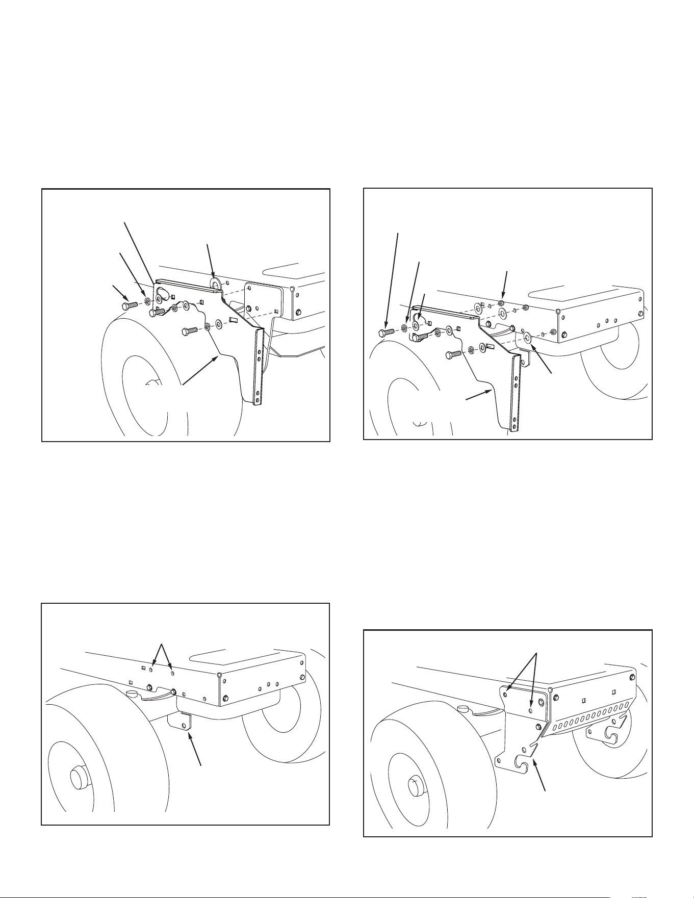
5. Fasten the R.H. hanger bracket (bend facing out) to the
holes indicated in the tractor frame.
If there is an engine mounting plate like the one
drawn with dotted lines in gure 3a, use large 1/2" at
washers (L) as shims between the hanger bracket and
the tractor frame in the locations shown in gure 3a. In
the front three holes use three 3/8" x 1" carriage bolts
(G), two large 1/2" washers (L) if needed, and three 3/8"
nylock nuts (K). In the rear hole use a 5/16" x 1" carriage
bolt (E), a large 1/2" washer (L) if needed, and a 5/16"
nylock nut (J).
If the tractor is a Husqvarna TS200 Series with dual
pedal there will be a bracket like the one drawn with
dotted lines in gure 3b. In the front three holes use
three 3/8" x 1" carriage bolts (G), three large 1/2" washers
(L), and three 3/8" nylock nuts (K). In the rear hole use
a 5/16" x 1" carriage bolt (E), and a 5/16" nylock nut (J).
Tighten all bolts. Repeat for the L.H. hanger bracket. See
gure 3.
6. Reinstall the browning shield then skip to step 21 on
page 7.
3/8" NYLOCK
NUT (K)
5/16" x 1"
CARRIAGE
BOLT (E)
3/8" x 1" CARRIAGE
BOLT (G)
ENGINE
MOUNTING
PLATE
1/2" LARGE
WASHER (L)
(IF NEEDED)
5/16" NYLOCK
NUT (J)
3/8" NYLOCK
NUT (K)
5/16" x 1"
CARRIAGE
BOLT (E)
3/8" x 1" CARRIAGE
BOLT (G)
1/2" LARGE
WASHER (L)
5/16" NYLOCK
NUT (J)
6
13. Attach the R.H. hanger bracket to the three holes shown on
the side of the tractor frame using three 3/8" x 1" hex bolts
(D), 3/8" lock washers (Q) and 3/8" at washers (M). Use
3/8" nylock nuts (K) on inside of frame if bolts insert freely
into holes. Tighten. See gure 8.
14. Repeat step 13 for other side.
15. Skip to step 21 on page 7.
NOTE: Use special 3/8" x 1" thread forming bolts (F) in any
holes that are too small for regular bolts.
FIGURE 8
3/8" x 1" HEX BOLT (D)
(OR THREAD FORMING
BOLT (F) IF NEEDED)
3/8" LOCK
WASHER (Q)
3/8" FLAT
WASHER (M)
3/8" NYLOCK NUT (K)
(IF NEEDED)
R.H. HANGER
BRACKET
1/2" LARGE
WASHER (N)
REMOVE BOLTS FROM THESE HOLES
FRONT SUSPENSION
BRACKET (R.H.)
FIGURE 9
INSTRUCTIONS FOR (GT) GARDEN
TRACTORS WITH DUAL SUSPENSION
BRACKETS
16. Remove the lower front hex bolt from the R.H. front
suspension bracket. See gure 9.
17. Remove the hex bolt from the hole at the rear of R.H.
front suspension bracket. See gure 9.
18. Repeat for the L.H. front suspension bracket.
FIGURE 6
1/2" LARGE
WASHER (L)
3/8" x 1"
HEX BOLT (D)
3/8" LOCK
WASHER (Q)
3/8" FLAT
WASHER (M)
R.H. HANGER
BRACKET
9. Attach the R.H. hanger bracket to the two front empty
holes on the right side of the tractor frame using two
new 3/8" x 1" hex bolts (D), 3/8" lock washers (Q), and
3/8" at washers (M) as shown. For the rear hole, use a
3/8" x 1" hex bolt (D), 3/8" lock washer (Q) and 3/8" at
washer (M) with a large 1/2" washer (L) placed between
the hanger bracket and the tractor frame. Tighten. See
gure 6.
10. Repeat step 9 for the left side.
11. Skip to step 21 on page 7.
FIGURE 7
REMOVE BOLTS FROM
THESE HOLES
FRONT
SUSPENSION
BRACKET
TYPE B TRACTORS
12. Remove any bolts found in the holes indicated in gure
7.
7
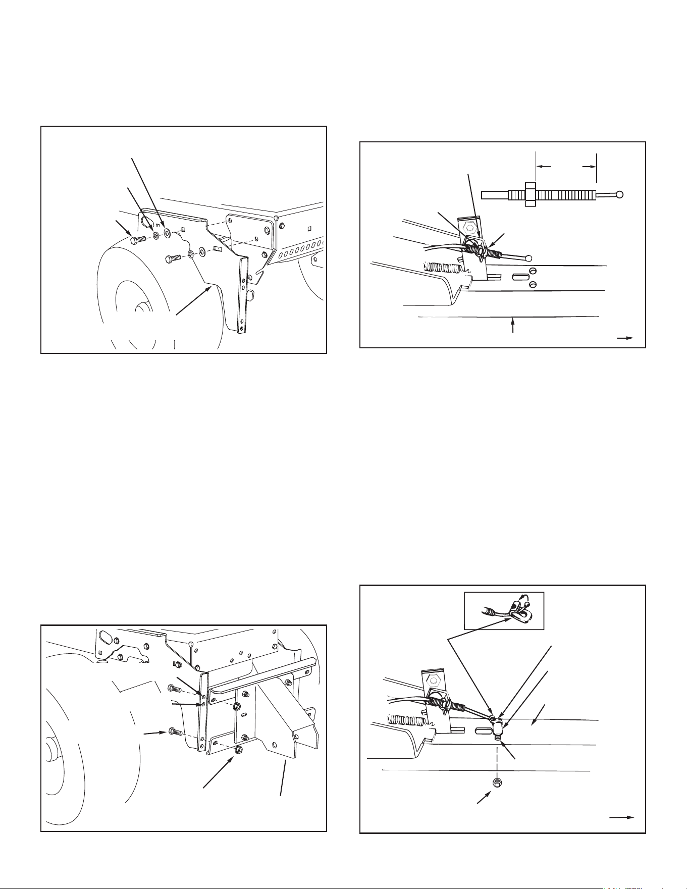
22. Assemble one 5/16" jam nut (H) approximately 3/4" onto
threaded end of control cable that has no rubber cap or
preassembled nuts. Assemble threaded cable end through
round hole in cable mount bracket and secure with another
5/16" jam nut (H). Tighten. See gure 12.
NOTE: Some adjustment of jam nuts may be required after
blade assembly is completed.
CHANNEL ASSEMBLY
5/16" JAM
NUT (H)
5/16" JAM
NUT (H)
CABLE MOUNT
BRACKET
REAR
3/4"
FIGURE 12 (Left Hand Side View)
23. Assemble ball end of control cable up through hole in
cable end tting and pull until ball slips inside curled edge
of tting. If ball won't slip under edge of curl, it will need
to be inserted through open end of curl. See gure 13.
24. Assemble 1/4" x 1-1/2" (B) hex bolt down through the
cable end tting, the 5/8" long spacer (A) and the left
hand hole in the channel assembly. Secure with a 1/4"
nylock nut (I). Tighten. See gure 13.
25. Align the cable mount bracket shown in gure 12 with
the cable end tting and tighten the carriage bolt and
nylock nut.
NOTE: Make sure the cable mount bracket is aligned with
the cable end tting to prevent binding of cable. The other
end of the control cable will be attached in a later step.
FIGURE 13 (Left Hand Side View)
1/4" x 1-1/2"
HEX BOLT (B)
CABLE END
FITTING
1/4" NYLOCK
NUT (I)
5/8" SPACER (A)
CHANNEL
ASSEMBLY
HOLE
REARREAR
3/8" x 1"
HEX BOLT (D)
3/8" LOCK
WASHER (Q)
3/8" FLAT
WASHER (M)
R.H. HANGER
BRACKET
FIGURE 10
19. Attach the R.H. hanger bracket to the front two holes in
the right side of the tractor frame using a new 3/8" x 1"
hex bolt (D), 3/8" lock washer (Q), and 3/8" at washer
(M) as shown in gure 10. Do not tighten yet.
20. Repeat step 19 for the L.H. hanger bracket.
INSTRUCTIONS FOR ALL TRACTORS
FIGURE 11
3/8" FLANGED
LOCK NUT (S)
PIVOT SUPPORT
ASSEMBLY
3/8" x 1"
HEX BOLT (D)
FOR GT TRACTORS
FOR LT TRACTORS
21. Attach the pivot support assembly to the hanger brackets,
using the upper holes for LT Tractors, or the lower holes
for GT Tractors. Use four 3/8" x 1" hex bolts (D) and 3/8"
anged lock nuts (S). Do not tighten yet. See gure 11.
8
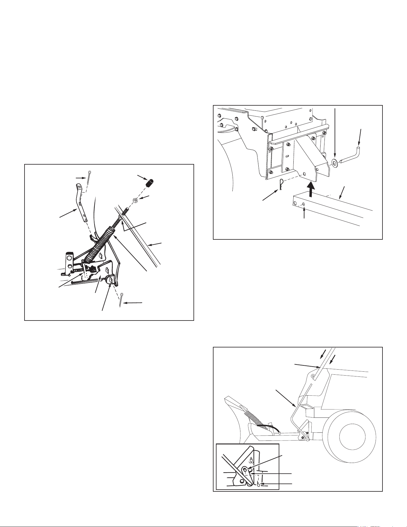
FIGURE 15 (Right Hand Side View)
28. Assemble the 1/2" washer (P) onto the channel pivot
pin. See gure 15.
29. Attach the channel assembly to the tractor by placing the
end of the channel assembly up inside the pivot support
bracket on the tractor. Align hole (a) in the channel
assembly with the hole in the pivot support bracket. Insert
the channel pivot pin through the aligned holes from the
left side, and secure it with a hairpin cotter (N).
30. From the left side, insert the welded end of the lift handle
rod through the hole in the end of the channel assembly
(Figure 16). Next, insert the lift link pin through the hole
in the bracket that is welded to the lift handle rod. (The
lift link is pre-assembled to the pivot support assembly).
Secure the bracket with a hairpin cotter (N) inserted up
through the lift link pin.
31. Apply a light coat of oil to the straight upper portion of
the lift handle rod. Slide the lift handle tube onto the rod.
FIGURE 16
(Left Hand Side View)
LIFT HANDLE ROD
HAIRPIN COTTER (N)
LONG PIN
(LIFT LINK)
WELDED BRACKET
LIFT HANDLE TUBE
HAIRPIN
COTTER (N)
CHANNEL
PIVOT PIN
1/2" WASHER (P)
CHANNEL
ASSEMBLY
HOLE (a)
(Right Hand Side View)
FIGURE 14
3/8" HEX NUT
(TOP)
PLASTIC
CAP
3/8" HEX NUT
(BOTTOM)
BLADE
1/8" x 1-1/4"
COTTER PIN (O)
BLADE
PIVOT
SHAFT
SPRING
MOUNT
ROD
BLADE
ADJUST
SPRING
1/8" x 1-1/4"
COTTER PIN (O)
PIVOT PLATE
NOTCHED HOLE
26. To attach the blade to the channel assembly, align the
notched holes in the pivot plate with the notched holes
in the blade. Insert a 1/8" x 1-1/4" cotter pin (O) down
through the hole at the bend in the blade pivot shaft.
Spread the ends of the pin. From the left side insert the
blade pivot shaft, bend facing top of blade, through the
notched holes. Secure the shaft with another 1/8" x 1-1/4"
cotter pin (O) through the end hole in the shaft. Spread
the ends of the pin. See gure 14.
27. Remove the plastic cap and one 3/8" hex nut from the
bolt in the blade adjust spring. Adjust the remaining 3/8"
hex nut down approximately 1" onto the bolt threads.
Hook the spring over the spring mount rod. Place the
bolt up through the hole in the top edge of the blade
and reassemble the other 3/8" hex nut to the bolt and
tighten down against the top edge of the blade. Replace
the plastic cap on the end of the bolt. See gure 14.
9
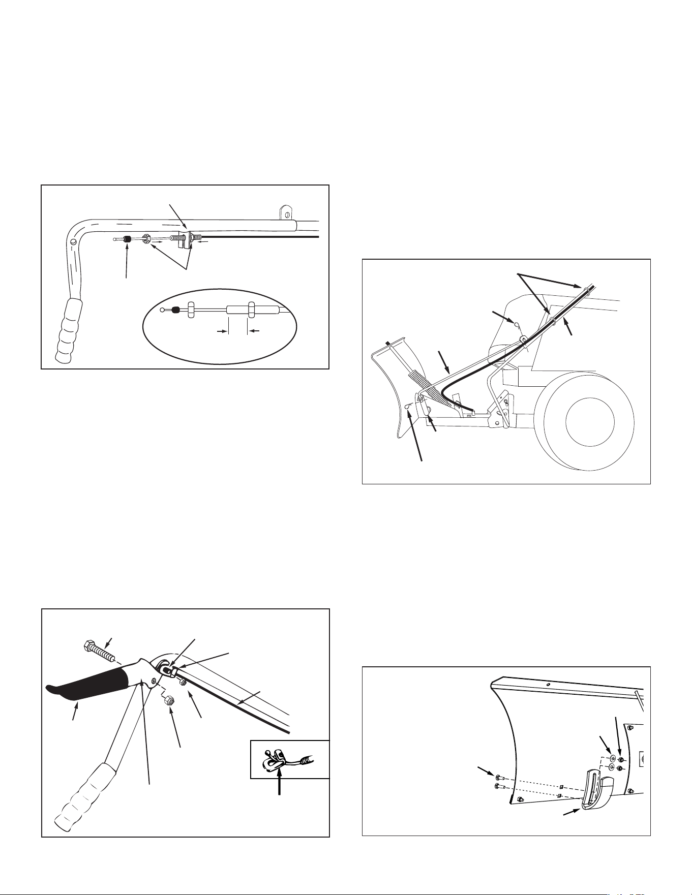
FIGURE 19 (Left Hand Side View)
36. Place the end of the blade pivot rod down through the
blade pivot shaft. Attach the other end of the blade pivot
rod to the lift handle tube. Secure both ends with a hairpin
cotter (N). The holes for the hairpin cotters should be
parallel to the ground. See gure 19.
37. Use two plastic ties to hold the cable securely to the
outside of the handle tube, away from the tractor to avoid
direct heat from the tractor muffler. See gure 19.
38. Squeeze the grip assembly to check if blade unlocks and
pivots. To adjust locking mechanism, see Adjustments
section on page 11.
BLADE PIVOT
ROD
LIFT HANDLE
TUBE
BLADE
PIVOT SHAFT
HAIRPIN
COTTER (N)
HAIRPIN COTTER (N)
PLASTIC TIES
39. Pivot the blade to the center position and lower it to
the ground. Place shims under the blade to create the
amount of ground clearance you want. The more uneven
the surface the more clearance you will need.
40. Attach the skid shoes to the blade using two 5/16" x 5/16"
x 1" carriage bolts (E), 5/16" washers (R) and 5/16" nylock
nuts (J). Tighten the bolts with the skid shoes resting on
the ground. See gure 20.
5/16" x 1"
CARRIAGE BOLT (E)
5/16" WASHER (R)
5/16" NYLOCK NUT (J)
SKID SHOE
FIGURE 20 (Left Hand Side View)
33. Assemble plastic grip onto lock release grip assembly.
See gure 18.
34. Attach lock release grip assembly to lift handle tube using
one 5/16" x 1-1/2" hex bolt (C) and one 5/16" nylock nut
(J). Do not overtighten the nut. The grip assembly must
pivot freely. See gure 18.
35. Assemble the ball end of the cable to a cable end tting
as you did to the other end of the cable. Secure the cable
end tting to the weld bolt on the lock release grip with a
1/4" nylock nut (I). Do not overtighten the lock nut. The
cable tting must pivot freely. See gure 18.
FIGURE 18
(Right Hand Side View)
5/16" x 1-1/2"
HEX BOLT (C)
PLASTIC
GRIP
LOCK RELEASE
GRIP ASSEMBLY
1/4" WELD
BOLT
CABLE END
FITTING
5/16" NYLOCK
NUT (J)
1/4" NYLOCK
NUT (I)
CABLE
CABLE END
FITTING
CABLE END
FITTING
FIGURE 17 (Right Hand Side View)
32. Remove the rubber cap and the rst jam nut from the
threaded end of the control cable and slide them onto
the control cable wire. Adjust the second jam nut on the
threads so that it is approximately 3/4" from end. Assemble
threaded end of cable through the cable mount bracket
and secure it with the rst jam nut. Reinstall the rubber
cap onto the threaded cable end. See gure 17.
NOTE: Some adjustment of jam nuts may be required
after blade assembly is completed.
RUBBER
CAP
CABLE MOUNT BRACKET
JAM NUTS
3/4"
CONTROL CABLE END
10
FIGURE 21
1. To raise the blade, use the handle grip located on the
end of the handle tube. Pull back while pushing down
on the handle grip. To lower blade, pull back while lifting
up on handle grip. See gure 21.
HANDLE TUBE
PULL BACK AND
LIFT UP TO
LOWER BLADE
PULL BACK AND
PUSH DOWN TO
RAISE BLADE
HANDLE GRIP
SECTION 2:
OPERATING THE BLADE
FIGURE 22
2. To unlock the blade, raise the blade to transport position.
Push the lock release grip down against the handle tube
to pivot the blade. Keep the grip depressed and push
forward or pull back on the handle tube, sliding it along
the lift rod. Release the grip to lock the blade when it
is in either the right hand, the left hand or the straight
ahead position. See gure 22.
HANDLE TUBE
LOCK RELEASE
GRIP ASSEMBLY
LIFT ROD
USING THE SNOW BLADE
3. Prepare the lawn tractor engine for cold weather using
instructions furnished with the lawn tractor.
4. Always begin with the transmission in rst (low) gear
and gradually increase speed as required.
5. Do not repeatedly push snow in the same direction. This
causes excessive build up with each successive pass.
6. To reduce icing on the blade, allow the lawn tractor and
blade to adjust to outdoor temperature before operating.
7. For improved snow removal performance, coat the blade
with automotive type paste wax.
CAUTION: Carefully inspect the area to be
worked before operating the snow blade.
Avoid pipes, roots, curbs or other heavy
obstructions.
CAUTION: Know the terrain. Avoid
exceptionally steep slopes or drop-offs which
may be hidden by the snow. Never run the
snow blade into heavy material at high speed.
CAUTION: Always lower the blade to the
ground before leaving the tractor.

11
SECTION 3:
MAINTENANCE
1. During the operating season, check all bolts, nuts and
hairpin cotters to be sure they are secure.
2. Lubricate all pivot points to help maintain proper
operation of blade.
3. Apply a light coating of oil to the upper portion of the
lift handle rod if the lift handle tube becomes difficult to
slide on the rod.
SECTION 4:
ADJUSTMENTS
To Adjust Blade Spring
1. The tension of the blade adjust spring may be altered to
permit the blade to tilt forward to bypass solid obstruc-
tions. To change the spring tension, adjust the nuts at
upper end of the spring bolt. Standing in front of blade,
turn the nuts counterclockwise to relieve tension and
clockwise to increase tension. Refer to gure 14 on
page 7.
To Adjust Blade Shoes
2. The blade shoes at the ends of blade may be raised for
close work on smooth surfaces or lowered to raise the
blade to work on rough or uneven areas. Make sure both
shoes are set evenly and that the nuts are tightened
securely. Refer to gure 20 on page 9.
To Adjust the Blade Pivot Lock Mechanism
3. If the blade will not unlock and pivot, the angle lock bars
are not disengaging from the slots in the pivot plate. To
correct, adjust the 5/16" hex jam nuts to draw the end of
the control cable back towards the cable mount bracket.
The less the threaded end of the cable extends through
the bracket, the more the angle lock bars can retract to
disengage from the slots in the pivot plate. See gure
23.
FIGURE 23
CABLE MOUNT BRACKET
5/16" HEX
JAM NUT
CONTROL
CABLE
5/16" HEX
JAM NUT
SECTION 5:
STORING THE BLADE
Recommendations When Storing
1. When the snow blade is not being used, remove all dirt
and rust and touch up with paint.
2. Touch up bare metal with paint or apply a light coat of
grease or rust preventive.
3. Lubricate all pivot points as instructed in the maintenance
section.
4. Store in a dry area, protected from weather.
To Remove Blade From Tractor
5. Lower the blade to the ground with the blade in the center
(straight ahead) position.
6. Remove the hairpin cotter which fastens the blade pivot
rod to the blade pivot shaft. See gure 19 on page 9.
7. Remove the hairpin cotter which fastens the lift handle
rod to the lift link pin. See gure 16, page 8.
8. Remove the hairpin cotter from the channel pivot pin
and remove the pivot pin from the channel assembly.
See gure 15 on page 8.
9. Remove the blade, the channel assembly and the
lift handle assembly from the tractor. The brackets
assembled to the tractor frame may be left in place.
10. To remove the brackets assembled to the tractor frame
(side plates and pivot support assembly) refer to the
gures appropriate for your tractor on pages 4 to 6.
11. If the side plates are removed from the tractor frame, be
sure to reassemble any bolts that were removed from the
frame. Refer to the gures appropriate for your tractor
on pages 4 to 6.

12

13
14
SUPPLEMENT SHEET
SUBJECT:
INTERFERENCE WITH BROWNING SHIELD AND LOWER DASH COVER
FORM NO. 42799 (05/06/13)
If your Husqvarna tractor is equipped with the browning shield shown below, it will be necessary to
remove it in order to mount this attachment. (Does not apply for front mount scoops). It is critical that
you reinstall the browning shield when the attachment is removed.
BROWNING SHIELD
LOWER DASH
COVER
If your Husqvarna TS200 Series tractor is equipped with lower dash covers as shown below, it will be necessary to
remove them in order to mount this attachment. (Does not apply for front mount dethatchers). Refer to
your tractor manual for removal instructions.
CAUTION!
down before removing browning
shield.

15
NOTES
Points de collecte sur www.quefairedemesdechets.fr
Privilégiez la réparaon ou le don de votre appareil !
À DÉPOSER
EN MAGASIN
À DÉPOSER
EN DÉCHÈTERIE
OU
Cet appareil
se recycle
FR
114 46 88-38

