CUB CADET LLC, P.O. BOX 361131 CLEVELAND, OHIO 44136-0019
Printed In USA
OperatOr’s Manual
Safe Operation Practices • Set-Up • Operation • Maintenance • Service • Troubleshooting • Warranty
WARNING
READ AND FOLLOW ALL SAFETY RULES AND INSTRUCTIONS IN THIS MANUAL
BEFORE ATTEMPTING TO OPERATE THIS MACHINE.
FAILURE TO COMPLY WITH THESE INSTRUCTIONS MAY RESULT IN PERSONAL INJURY.
Zero Turn Riding Mower
Time Saver Model
i1042
FORM NO. 769-03654
(Nov, 2007)

Customer Support
If you have difficulty assembling this product or have any questions regarding the controls, operation, or maintenance of
this machine, you can seek help from the experts. Choose from the options below:
Visit us on the web at www.cubcadet.com
Locate your nearest Cub Cadet Dealer at (877) 282-8684
Write us at Cub Cadet LLC • P.O. Box 361131 • Cleveland, OH • 44136-0019
◊
◊
◊
Thank you for purchasing a Lawn Tractor manufactured by Cub
Cadet LLC. It was carefully engineered to provide excellent
performance when properly operated and maintained.
Please read this entire manual prior to operating the equipment.
It instructs you how to safely and easily set up, operate and
maintain your machine. Please be sure that you, and any other
persons who will operate the machine, carefully follow the
recommended safety practices at all times. Failure to do so could
result in personal injury or property damage.
All information in this manual is relative to the most recent
product information available at the time of printing. Review
this manual frequently to familiarize yourself with the machine,
its features and operation. Please be aware that this Operator’s
Manual may cover a range of product specifications for various
models. Characteristics and features discussed and/or illustrated
in this manual may not be applicable to all models. Cub Cadet
LLC reserves the right to change product specifications, designs
and equipment without notice and without incurring obligation.
This product has met the rigid safety standards of the Outdoor
Power Equipment Institute and an independent testing
laboratory. If you have any problems or questions concerning
the machine, phone your local Cub Cadet dealer or contact us
directly. Cub Cadet’s Customer Support telephone numbers,
website address and mailing address can be found on this page.
We want to ensure your complete satisfaction at all times.
Throughout this manual, all references to right and left side of the
machine are observed from the operating position.
Thank You
Record Product Information
Before setting up and operating your new equipment, please
locate the model plate on the equipment and record the
information in the provided area to the right. You can locate the
model plate by looking beneath the seat. This information will be
necessary, should you seek technical support via our web site or
with your local Cub Cadet dealer.
MOdel nuMber
serial nuMber
To The Owner
1
2
Safe Operation Practices ........................................ 3
Assembly & Set-Up .................................................. 8
Controls & Features ................................................ 9
Operation ................................................................12
Maintenance & Adjustment .................................15
Service .................................................................... 20
Troubleshooting .................................................... 25
Replacement Parts ............................................... 26
Attachments & Accessories .................................. 26
Warranty ................................................. Back Cover
Table of Contents
Important Safe Operation Practices
2
3
Children
Tragic accidents can occur if the operator is not alert to the
presence of children. Children are often attracted to the
machine and the mowing activity. They do not understand
the dangers. Never assume that children will remain where
you last saw them.
Keep children out of the mowing area and in
watchful care of a responsible adult other than the
operator.
Be alert and turn machine off if a child enters the
area.
Before and while backing, look behind and down for
small children.
Never carry children, even with the blade(s) shut off.
They may fall off and be seriously injured or interfere
with safe machine operation.
Use extreme care when approaching blind corners,
doorways, shrubs, trees or other objects that may
block your vision of a child who may run into the
machine.
To avoid back-over accidents, always disengage
the cutting blade(s) before shifting into Reverse.
If equipped, the “Reverse Caution Mode” should
not be used when children or others are around.
1.
a.
b.
c.
d.
e.
f.
Keep children away from hot or running engines.
They can suffer burns from a hot muffler.
Remove key when machine is unattended to
prevent unauthorized operation.
Never allow children under 14 years of age to operate this
machine. Children 14 and over should read and understand
the instructions and safe operation practices in this manual
and on the machine and should be trained and supervised
by an adult.
Operation
Safe Handling of Gasoline:
To avoid personal injury or property damage use extreme
care in handling gasoline. Gasoline is extremely
flammable and the vapors are explosive. Serious
personal injury can occur when gasoline is spilled on
yourself or your clothes which can ignite. Wash your skin
and change clothes immediately.
Use only an approved gasoline container.
Never fill containers inside a vehicle or on a truck
or trailer bed with a plastic liner. Always place
containers on the ground away from your vehicle
before filling.
g.
h.
2.
1.
a.
b.
WARNING: This symbol points out important safety instructions which, if not followed,
could endanger the personal safety and/or property of yourself and others. Read and follow
all instructions in this manual before attempting to operate this machine. Failure to comply
with these instructions may result in personal injury.
When you see this symbol. HEED ITS WARNING!
DANGER: This machine was built to be operated according to the rules for safe operation
practices in this manual. As with any type of power equipment, carelessness or error on the
part of the operator can result in serious injury. This machine is capable of amputating hands
and feet and throwing objects. Failure to observe the following safety instructions could
result in serious injury or death.
CALIFORNIA PROPOSITION 65
WARNING: Engine Exhaust, some of its constituents, and certain vehicle components
contain or emit chemicals known to State of California to cause cancer and birth defects
or other reproductive harm.
WARNING: Battery posts, terminals, and related accessories contain lead and lead
compounds, chemicals known to the State of California to cause cancer and reproductive
harm. Wash hands after handling

4 sectiOn 2 — iMpOrtant safe OperatiOn practices
When practical, remove gas-powered equipment
from the truck or trailer and refuel it on the ground.
If this is not possible, then refuel such equipment on
a trailer with a portable container, rather than from a
gasoline dispenser nozzle.
Keep the nozzle in contact with the rim of the fuel
tank or container opening at all times until fueling is
complete. Do not use a nozzle lock-open device.
Extinguish all cigarettes, cigars, pipes and other
sources of ignition.
Never fuel machine indoors.
Never remove gas cap or add fuel while the engine
is hot or running. Allow engine to cool at least two
minutes before refueling.
Never over fill fuel tank. Fill tank to no more than ½
inch below bottom of filler neck to allow space for
fuel expansion.
Replace gasoline cap and tighten securely.
If gasoline is spilled, wipe it off the engine and
equipment. Move machine to another area. Wait 5
minutes before starting the engine.
To reduce fire hazards, keep machine free of grass,
leaves, or other debris build-up. Clean up oil or fuel
spillage and remove any fuel soaked debris.
Never store the machine or fuel container inside
where there is an open flame, spark or pilot light
as on a water heater, space heater, furnace, clothes
dryer or other gas appliances.
Allow a machine to cool at least five minutes before
storing.
General Operation:
Read, understand, and follow all instructions on the
machine and in the manual(s) before attempting to
assemble and operate. Keep this manual in a safe place for
future and regular reference and for ordering replacement
parts.
Be familiar with all controls and their proper operation.
Know how to stop the machine and disengage them
quickly.
Never allow children under 14 years old to operate this
machine. Children 14 years old and over should read and
understand the operation instructions and safety rules in
this manual and should be trained and supervised by a
parent.
Never allow adults to operate this machine without proper
instruction.
To help avoid blade contact or a thrown object injury,
keep bystanders, helpers, children and pets at least 75 feet
from the machine while it is in operation. Stop machine if
anyone enters the area.
Thoroughly inspect the area where the equipment is to be
used. Remove all stones, sticks, wire, bones, toys, and other
foreign objects which could be picked up and thrown by
the blade(s). Thrown objects can cause serious personal
injury.
c.
d.
e.
f.
g.
h.
i.
j.
k.
l.
m.
1.
2.
3.
4.
5.
6.
Plan your mowing pattern to avoid discharge of material
toward roads, sidewalks, bystanders and the like. Also,
avoid discharging material against a wall or obstruction
which may cause discharged material to ricochet back
toward the operator.
Always wear safety glasses or safety goggles during
operation and while performing an adjustment or repair
to protect your eyes. Thrown objects which ricochet can
cause serious injury to the eyes.
Wear sturdy, rough-soled work shoes and close-fitting
slacks and shirts. Loose fitting clothes and jewelry can be
caught in movable parts. Never operate this machine in
bare feet or sandals.
Be aware of the mower and attachment discharge direction
and do not point it at anyone. Do not operate the mower
without the discharge cover or entire grass catcher in its
proper place.
Do not put hands or feet near rotating parts or under the
cutting deck. Contact with the blade(s) can amputate
hands and feet.
A missing or damaged discharge cover can cause blade
contact or thrown object injuries.
Stop the blade(s) when crossing gravel drives, walks, or
roads and while not cutting grass.
Watch for traffic when operating near or crossing
roadways. This machine is not intended for use on any
public roadway.
Do not operate the machine while under the influence of
alcohol or drugs.
Mow only in daylight or good artificial light.
Never carry passengers.
Disengage blade(s) before shifting into reverse. Back up
slowly. Always look down and behind before and while
backing to avoid a back-over accident.
Slow down before turning. Operate the machine smoothly.
Avoid erratic operation and excessive speed.
Disengage blade(s), set parking brake, stop engine and
wait until the blade(s) come to a complete stop before
removing grass catcher, emptying grass, unclogging chute,
removing any grass or debris, or making any adjustments.
Never leave a running machine unattended. Always turn
off blade(s), place transmission in neutral, set parking
brake, stop engine and remove key before dismounting.
Use extra care when loading or unloading the machine into
a trailer or truck. This machine should not be driven up or
down ramp(s), because the machine could tip over, causing
serious personal injury. The machine must be pushed
manually on ramp(s) to load or unload properly.
Muffler and engine become hot and can cause a burn. Do
not touch.
Check overhead clearances carefully before driving under
low hanging tree branches, wires, door openings etc.,
where the operator may be struck or pulled from the
machine, which could result in serious injury.
7.
8.
9.
10.
11.
12.
13.
14.
15.
16.
17.
18.
19.
20.
21.
22.
23.
24.

5sectiOn 2 — iMpOrtant safe OperatiOn practices
Disengage all attachment clutches, depress the brake
pedal completely and shift into neutral before attempting
to start engine.
Your machine is designed to cut normal residential grass of
a height no more than 10”. Do not attempt to mow through
unusually tall, dry grass (e.g., pasture) or piles of dry leaves.
Dry grass or leaves may contact the engine exhaust and/or
build up on the mower deck presenting a potential fire
hazard.
Use only accessories and attachments approved for this
machine by the machine manufacturer. Read, understand
and follow all instructions provided with the approved
accessory or attachment.
Data indicates that operators, age 60 years and above, are
involved in a large percentage of riding mower-related
injuries. These operators should evaluate their ability
to operate the riding mower safely enough to protect
themselves and others from serious injury.
If situations occur which are not covered in this manual, use
care and good judgment. Contact your customer service
representative for assistance.
Slope Operation:
Slopes are a major factor related to loss of control and tip-over
accidents which can result in severe injury or death. All slopes
require extra caution. If you cannot back up the slope or if you
feel uneasy on it, do not mow it.
For your safety, use the slope gauge included as part of this
manual to measure slopes before operating this machine on
a sloped or hilly area. If the slope is greater than 15 degrees as
shown on the slope gauge, do not operate this machine on that
area or serious injury could result.
Do:
Mow up and down slopes, not across. Exercise extreme
caution when changing direction on slopes.
Watch for holes, ruts, bumps, rocks, or other hidden
objects. Uneven terrain could overturn the machine. Tall
grass can hide obstacles.
Use slow speed. Choose a low enough speed setting so
that you will not have to stop or shift while on the slope.
Tires may lose traction on slopes even though the brakes
are functioning properly. Always keep machine in gear
when going down slopes to take advantage of engine
braking action.
Follow the manufacturer’s recommendations for wheel
weights or counterweights to improve stability.
Use extra care with grass catchers or other attachments.
These can change the stability of the machine.
Keep all movement on the slopes slow and gradual. Do
not make sudden changes in speed or direction. Rapid
engagement or braking could cause the front of the
machine to lift and rapidly flip over backwards which could
cause serious injury.
Avoid starting or stopping on a slope. If tires lose traction,
disengage the blade(s) and proceed slowly straight down
the slope.
25.
26.
27.
28.
29.
1.
2.
3.
4.
5.
6.
7.
Do Not:
Do not turn on slopes unless necessary; then, turn slowly
and gradually downhill, if possible.
Do not mow near drop-offs, ditches or embankments. The
mower could suddenly turn over if a wheel is over the edge
of a cliff, ditch, or if an edge caves in.
Do not try to stabilize the machine by putting your foot on
the ground.
Do not use a grass catcher on steep slopes.
Do not mow on wet grass. Reduced traction could cause
sliding.
Do not shift to neutral and coast downhill. Over-speeding
may cause the operator to lose control of the machine
resulting in serious injury or death.
Do not tow heavy pull behind attachments (e.g. loaded
dump cart, lawn roller, etc.) on slopes greater than 5
degrees. When going down hill, the extra weight tends
to push the tractor and may cause you to loose control.
(e.g. tractor may speed up, braking and steering ability are
reduced, attachment may jack-knife and cause tractor to
overturn).
Towing:
Tow only with a machine that has a hitch designed for
towing. Do not attach towed equipment except at the
hitch point.
Follow the manufacturers recommendation for weight
limits for towed equipment and towing on slopes.
Never allow children or others in or on towed equipment.
On slopes, the weight of the towed equipment may cause
loss of traction and loss of control.
Travel slowly and allow extra distance to stop.
Do not shift to neutral and coast downhill.
Service
Never run an engine indoors or in a poorly ventilated area.
Engine exhaust contains carbon monoxide, an odorless,
and deadly gas.
Before cleaning, repairing, or inspecting, make certain the
blade(s) and all moving parts have stopped. Disconnect the
spark plug wire and ground against the engine to prevent
unintended starting.
Periodically check to make sure the blades come to
complete stop within approximately (5) five seconds after
operating the blade disengagement control. If the blades
do not stop within the this time frame, your machine
should be serviced professionally by an authorized MTD
Service Dealer.
Check brake operation frequently as it is subjected to wear
during normal operation. Adjust and service as required.
1.
2.
3.
4.
5.
6.
7.
1.
2.
3.
4.
5.
6.
1.
2.
3.
4.

6 sectiOn 2 — iMpOrtant safe OperatiOn practices
Check the blade(s) and engine mounting bolts at frequent
intervals for proper tightness. Also, visually inspect blade(s)
for damage (e.g., excessive wear, bent, cracked). Replace
the blade(s) with the original equipment manufacturer’s
(O.E.M.) blade(s) only, listed in this manual. “Use of parts
which do not meet the original equipment specifications
may lead to improper performance and compromise
safety!”
Mower blades are sharp. Wrap the blade or wear gloves,
and use extra caution when servicing them.
Keep all nuts, bolts, and screws tight to be sure the
equipment is in safe working condition.
Never tamper with the safety interlock system or other
safety devices. Check their proper operation regularly.
After striking a foreign object, stop the engine, disconnect
the spark plug wire(s) and ground against the engine.
Thoroughly inspect the machine for any damage. Repair
the damage before starting and operating.
Never attempt to make adjustments or repairs to the
machine while the engine is running.
Grass catcher components and the discharge cover are
subject to wear and damage which could expose moving
parts or allow objects to be thrown. For safety protection,
frequently check components and replace immediately
with original equipment manufacturer’s (O.E.M.) parts only,
listed in this manual. “Use of parts which do not meet the
original equipment specifications may lead to improper
performance and compromise safety!”
Do not change the engine governor settings or over-speed
the engine. The governor controls the maximum safe
operating speed of the engine.
Maintain or replace safety and instruction labels, as
necessary.
Observe proper disposal laws and regulations for gas, oil,
etc. to protect the environment.
Do not modify engine
To avoid serious injury or death, do not modify engine in any
way. Tampering with the governor setting can lead to a runaway
engine and cause it to operate at unsafe speeds. Never tamper
with factory setting of engine governor.
5.
6.
7.
8.
9.
10.
11.
12.
13.
14.
Notice Regarding Emissions
Engines which are certified to comply with California and federal
EPA emission regulations for SORE (Small Off Road Equipment)
are certified to operate on regular unleaded gasoline, and
may include the following emission control systems: Engine
Modification (EM) and Three Way Catalyst (TWC) if so equipped.
Spark Arrestor
WARNING: This machine is equipped with an
internal combustion engine and should not be used
on or near any unimproved forest-covered,
brushcovered or grass-covered land unless the
engine’s exhaust system is equipped with a spark
arrester meeting applicable local or state laws (if
any).
If a spark arrester is used, it should be maintained in effective
working order by the operator. In the State of California the
above is required by law (Section 4442 of the California Public
Resources Code). Other states may have similar laws. Federal laws
apply on federal lands.
A spark arrester for the muffler is available through your
nearest engine authorized service dealer or contact the service
department, P.O. Box 361131 Cleveland, Ohio 44136-0019.
Average Useful Life
According to the Consumer Products Safety Commission
(CPSC) and the U.S. Environmental Protection Agency (EPA),
this product has an Average Useful Life of seven (7) years, or 270
hours of operation. At the end of the Average Useful Life, buy
a new machine or have the machine inspected annually by an
authorized service dealer to ensure that all mechanical and
safety systems are working properly and not worn excessively.
Failure to do so can result in accidents, injuries or death.
WARNING: Your Responsibility—Restrict the use of this power machine to persons who read, understand and
follow the warnings and instructions in this manual and on the machine.
SAVE THESE INSTRUCTIONS!
7sectiOn 2 — safe OperatiOn practices
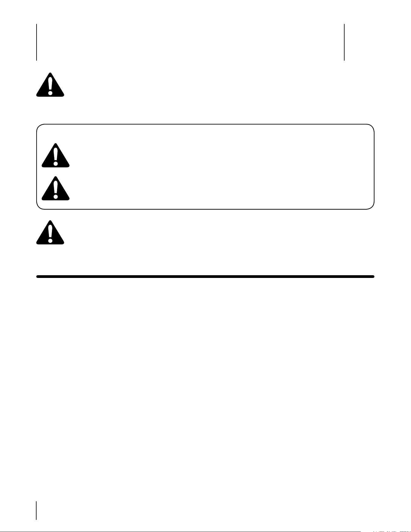
Sight and hold this level with a vertical tree...
or a corner of a building...
or a fence post
Fold along dotted line (represents a 15° slope)
15°
Use this page as a guide to determine slopes where you may not operate safely.
WARNING: Do not operate your lawn mower on such slopes. Do not mow on inclines with a slope in excess of 15 degrees
(a rise of approximately 2-1/2 feet every 10 feet). A riding mower could overturn and cause serious injury. Operate riding
mowers up and down slopes, never across the face of slopes.
Assembly & Set-Up
3
8
Gasoline Fill-up
WARNING: Use extreme care when handling
gasoline. Gasoline is extremely flammable and
the vapors are explosive. Never fuel machine
indoors or while the engine is hot or running.
Extinguish cigarettes, cigars, pipes, and other
sources of ignition.
nOte: Purchase gasoline in small quantities. Do not use
gasoline left over from the previous season, to minimize
gum deposits in the fuel system.
This engine is certified to operate on unleaded
gasoline. For best results, fill the fuel tank with only
clean, fresh, unleaded gasoline with a pump sticker
octane rating of 87 or higher. In countries using the
Research method, it should be 90 octane minimum.
Unleaded gasoline is recommended because it leaves
less combustion chamber deposits and reduces
harmful exhaust emissions. Leaded gasoline is not
recommended and must not be used where exhaust
emissions are regulated.
Gasohol (up to 10% ethyl alcohol, 90% unleaded
gasoline by volume) is an approved fuel. Other
gasoline/alcohol blends are not approved.
Methyl Tertiary Butyl Ether (MTBE) and unleaded
gasoline blends (up to a maximum of 15% MTBE by
volume) are approved fuels. Other gasoline/ether
blends are not approved.
The gasoline tank is under the rear fender, with the fuel fill
cap located in the center of the rear fender. The fuel cap is
tethered to the tractor to prevent its loss. Do not attempt
to remove the cap from the tractor.
IMPORTANT: Your tractor is shipped with motor oil in
the engine. However, you MUST check the oil level before
operating. Refer to the engine Owner’s Manual provided with
your tractor for instructions on checking the oil level.
Tire Pressure
WARNING: Maximum tire pressure under any
circumstances is 25 psi. Equal tire pressure
should be maintained at all times.
The tires on your unit may be over-inflated for shipping
purposes. Reduce the tire pressure before operating
the tractor. Recommended operating tire pressure is
approximately 10 p.s.i for the rear tires & 14 p.s.i. for the
front tires. Check sidewall of tire for maximum p.s.i.
•
•
•
•
Opening the Tractor Hood
To attach the negative battery cable and check the engine
oil level the hood must be open. Locate the hood lift notch
(Refer to Figure 4 on page 10) at the front/center of the
dash panel. Grasping the hood at the notch, lift and pivot
the hood forward to open.
Attaching the Battery Cables
The tractor is shipped with an activated sealed battery. The
positive battery cable is factory connected. The negative
cable must be connected. The positive battery terminal is
marked Pos. (+). The negative battery terminal is marked
Neg. (–).
IMPORTANT: Make sure the ignition switch is in the “OFF”
position before attaching the battery cables.
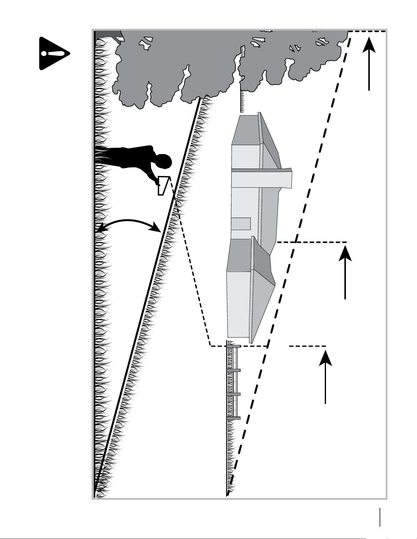
From the center notch at the front of the dash panel,
lift the tractor hood and pivot forward to open.
Remove the hex shoulder bolt and wing nut from the
negative (black)cable.
Figure 3-1
Pull the protective cap, if present, off the negative
battery terminal. Attach the negative cable (heavy
black wire) to the negative battery terminal (–) with
the bolt and wing nut. See Figure 1.
The positive cable (red cable) is secured to the positive
battery terminal (+) with a carriage bolt and hex sems
nut at the factory. Make certain that the rubber boot
covers the positive battery terminal.
NOTE: If the battery is put into service after the date
shown on top of battery, charge the battery as instructed
on page 20 of this manual prior to operating the tractor.
•
•
•
•
Shoulder Bolt
Wing Nut
Negative
Battery
Cable
Controls and Features
4
9
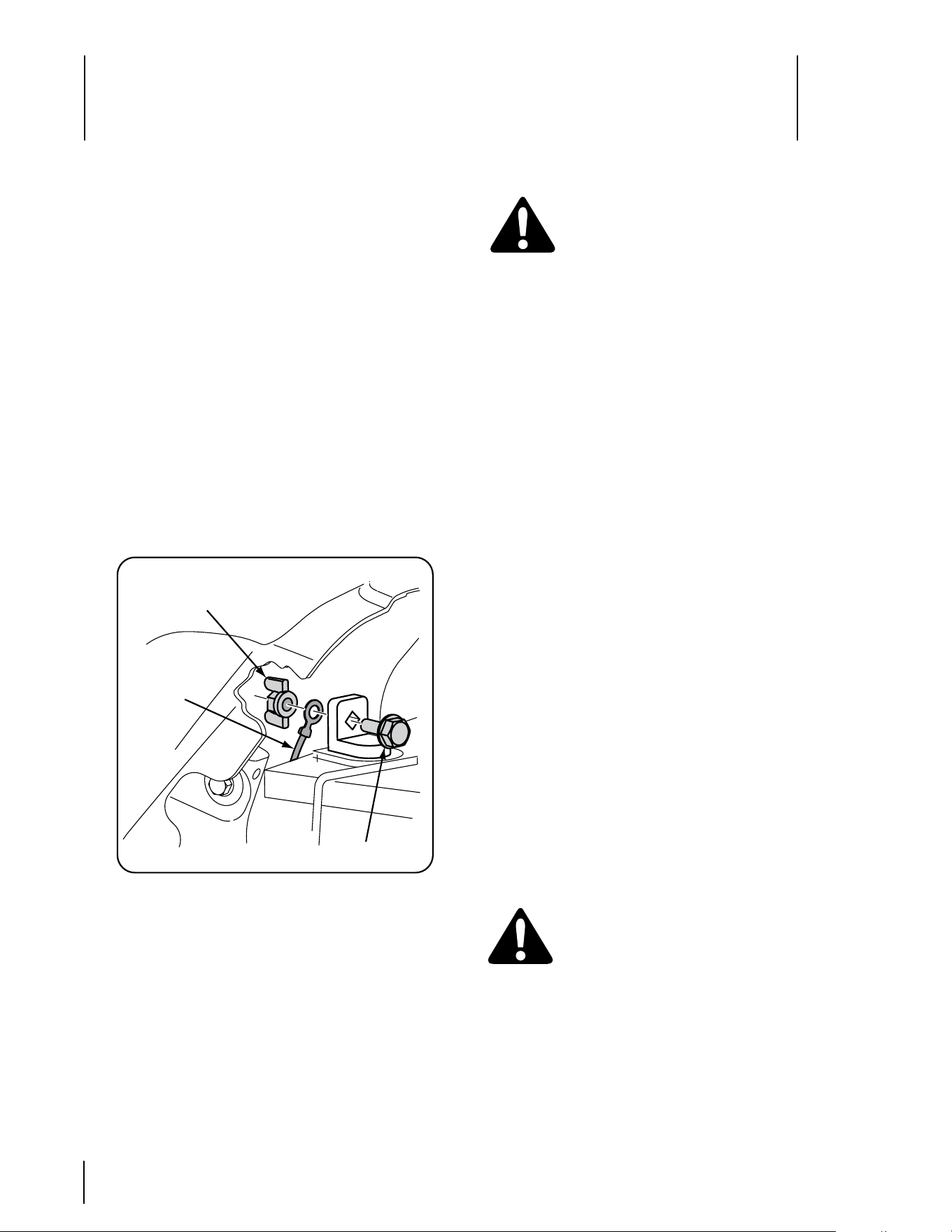
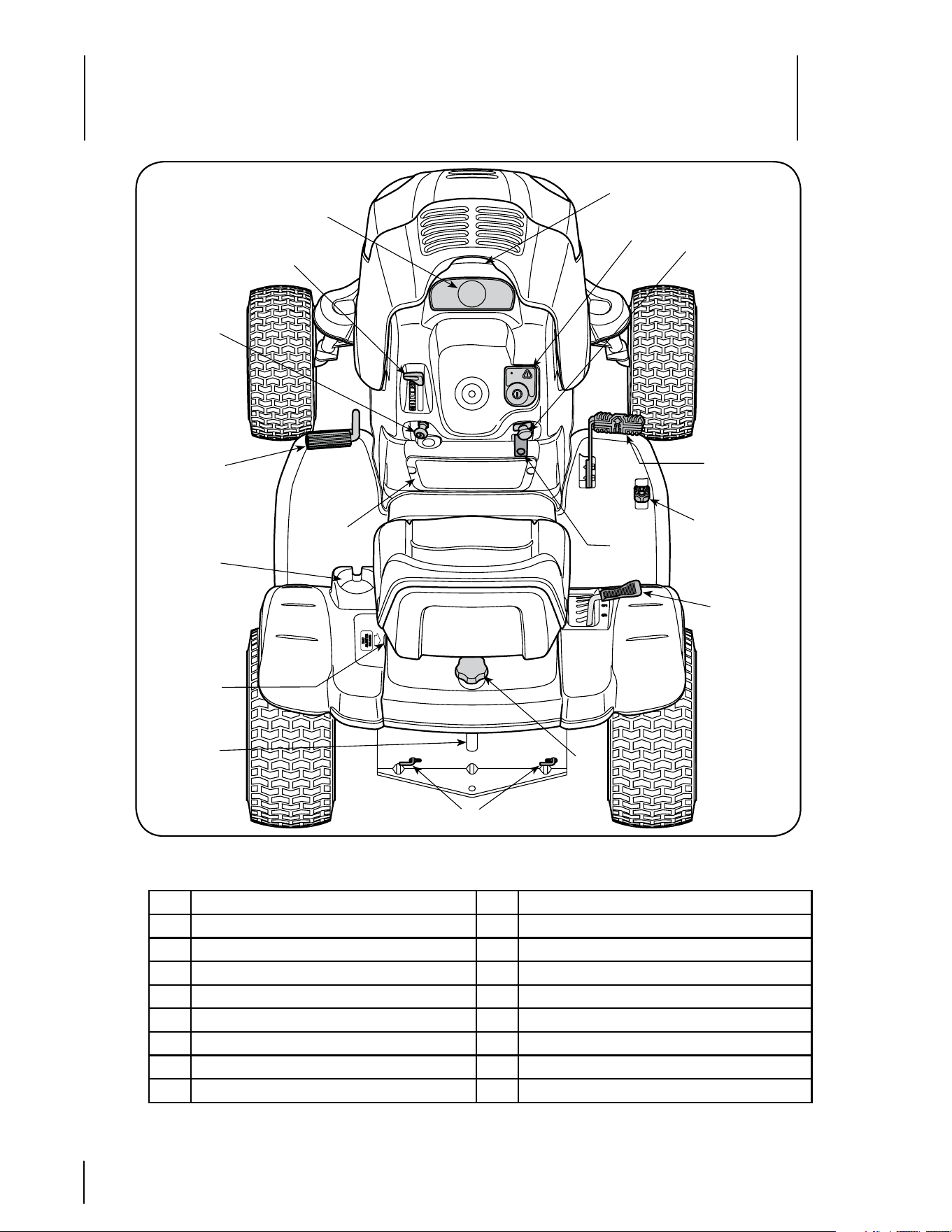
Figure 4-1
C
A Systems Indicator Monitor/ Hour Meter J Deck Lift Lever
B Throttle Control Lever K Cup Holder
C Key Switch Module L Seat Adjustment Lever
D Choke Control Knob M Fuel Fill Cap
E PTO (Blade Engage)Control Switch N Hydro Transmission Bypass Rods
F Parking Brake Lever O Fuel Level Window
G Forward Control Pedal P Cargo Net
H Reverse Control Pedal Q Hood Lift Notch
I Brake Pedal
A
B
D
E
F
G
H
I
J
K
L
M
O
N
P
Q
NOTE: Any reference in this manual to the RIGHT or LEFT side of the tractor is observed from operator’s position.
10 sectiOn 4— cOntrOls and features
Oil Pressure Indicator Light
This warning lamp indicates low engine oil pressure. If this
indicator illuminates, stop the tractor immediately and check the
engine oil level. If the oil level is within the operating range, but the
light remains on, contact your Cub Cadet dealer. NOTE: The oil
pressure indicator may illuminate when the key switch is turned to
an on position, but should turn off when the engine is started.
PTO Engaged Indicator Light
This indicator illuminates when the key switch is turned to the
“START” position while the PTO switch is in the “ENGAGED”
position. Check this indicator if the engine will not crank with the
key switch in the “START” position. Move the PTO switch to the
“DISENGAGED” position.
Brake Engaged Indicator
This indicator illuminates when the key switch is turned to the
“START” position and the brake pedal is not fully depressed. Check
this indicator if the engine will not crank with the key switch in the
“START” position. If necessary, fully depress the brake pedal. ..
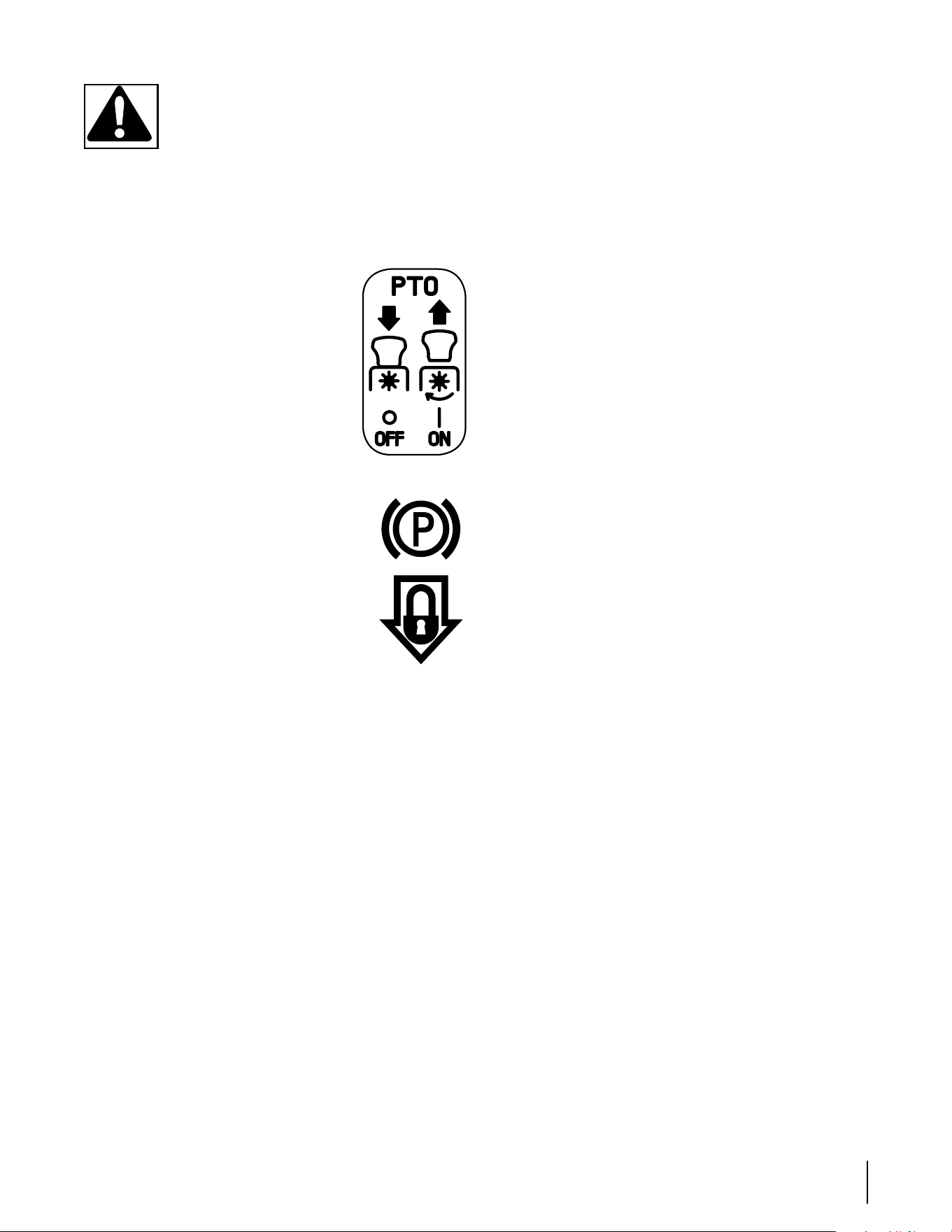
Throttle Control Lever
The throttle control lever controls the speed
of the engine. When set in a given position,
the throttle will maintain a uniform engine
speed.
IMPORTANT: When operating the tractor
with the cutting deck engaged, throttle
control lever must always be in the FAST
(rabbit) position.
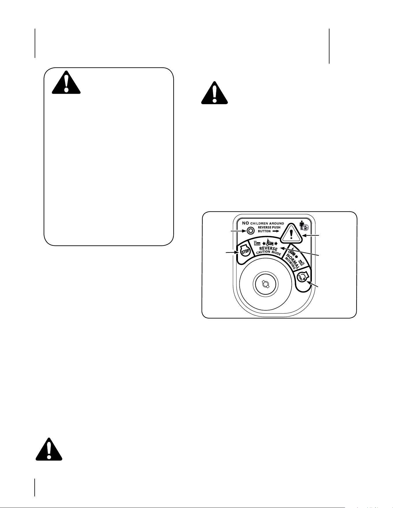
Key Switch Module
The key switch module is used to
start and stop the engine. It is also
used to activate the REvERSE
CAuTION MODE. Insert key into
the key switch module and turn
clockwise to the START position.
Release the key into the NORMAl
MOWING position once engine
has started.
To stop the engine, turn the ignition
key counterclockwise to the STOP
position.
WARNING: Never leave a running machine
unattended. Always disengage PTO, move shift
lever into neutral position, set parking brake, stop
engine and remove key to prevent unintended
starting.
IMPORTANT: Prior to operating the tractor, refer to both “Safety
Interlock System” on page 12 and “Starting The Engine” on page
13 of this manual for detailed instructions regarding the Ignition
Switch Module and operating the tractor in REvERSE CAuTION
MODE.
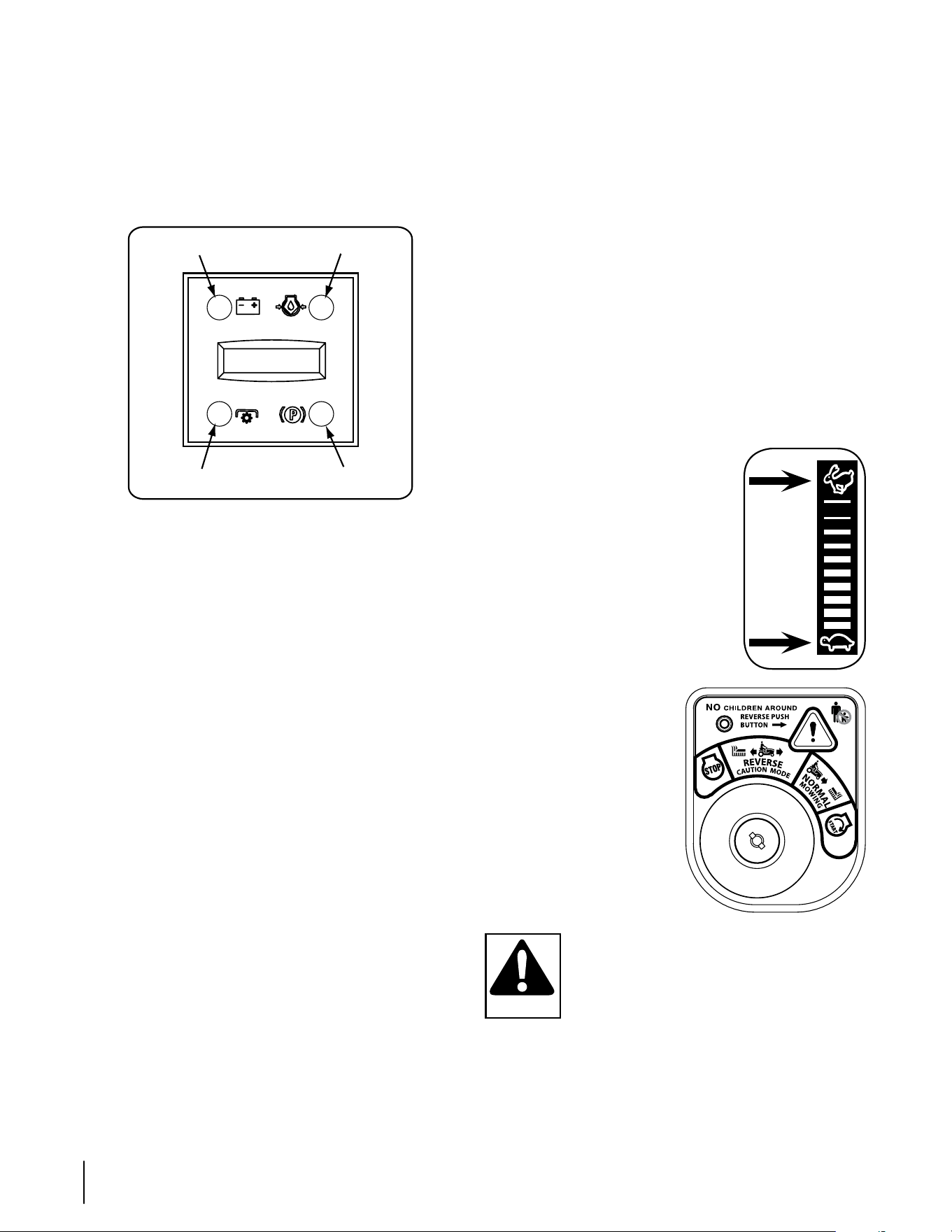
Systems Indicator Monitor/Hour Meter
Your tractor is equipped with a Systems Indicator Monitor as
shown in Figure 5. The monitor records the accumulated hours
of tractor operation, and displays the information on the lCD hour
meter display (tenths of an hour - right most digit). The monitor
also has four indicator lights that show the status of various
functions of the tractor.
Figure 4-2
The system indicator monitor features are as follows:
LCD Hour Meter Display
The hour meter display is activated when the key switch is
turned to either the “NORMAl MOWING” or the “REvERSE
CAuTION MODE” switch positions. When the key switch is
turned to an on position, the battery indicator light briefly
illuminates and the battery voltage is briefly displayed. The
display then changes to the accumulated hours.
NOTE: A record of the actual hours of operation should be kept
to assure maintenance procedures are completed according to
the schedule in this manual.
The Indicator Monitor will also remind the operator of main-
tenance intervals for changing the engine oil. The lCD will
alternately flash the recorded hours, “CHG” and “OIl” for five
minutes, after every 50 hours of recorded operation elapse. The
maintenance interval lasts for two hours (from 50-52, 100-102,
150-152, etc.). The lCD will flash as described for five minutes
every time the tractor’s engine is started during this maintenance
interval. Follow the oil change intervals provided in the engine
manual this the Maintaining your Tractor section of this Manual.
Battery Indicator Light
Illuminates when the ignition switch it turned to an ON position and
the engine is not started.
Illuminates to indicate the battery voltage has dropped below 11.5
(+0.5/-1.0) DC volts (the battery voltage is also displayed on the
hour meter). If this indicator and display come on during operation,
check the battery and charging system for possible causes and/or
contact your Cub Cadet dealer.
Fast
Position
Slow
Position
Battery
LCD Hour Meter
PTO
Oil
Parking Brake
123.4
11sectiOn 4 — cOntrOls and features
WARNING: Never move the key into the Start
position while the engine is running. Doing so
may cause damage to your engine’s starter.
Choke Control
The choke control knob is located on the lower left side of the dash
panel and is activated by pulling outward. Activating the choke
control closes the choke plate on the carburetor and aids in starting
the engine.
PTO (Blade Engage) Control
Switch
To engage the electric PTO and provide power
to the cutting deck, pull outward on the PTO
control switch knob. Push the switch knob
inward to disengage the PTO and stop the
cutting deck.
NOTE: The PTO Control Switch must be in the
disengaged (OFF) position when starting the
engine.
Parking Brake Lever
NOTE: The parking brake must be set if the
operator leaves the seat with the engine running;
otherwise the engine will automatically shut off.
• To set the parking brake, fully depress the brake
pedal and push the bottom of parking brake
lever inward. See the image to the right for
parking brake identification. Hold the lever in
while removing your foot from the brake pedal.
Both parking brake lever and brake pedal will
stay depressed.
• To release the parking brake, depress the brake pedal slightly.
The parking brake lever will then return to its original position.
IMPORTANT: Always set the parking brake when leaving the
tractor unattended.
Forward Control Pedal
The forward control pedal is located on the right side of the tractor,
at the front of the right running board. Depress the forward control
pedal to cause the tractor to travel in the forward direction. The for-
ward ground speed of the tractor is directly affected by the distance
the pedal is depressed. The further the pedal is depressed, the
faster the tractor will travel. The tractor will slow and the pedal will
return to its original position when released.
Reverse Control Pedal
The reverse control pedal is located in the right front running board
rearward of the forward control pedal. Depress the reverse control
pedal to cause the tractor to travel in reverse. The further the pedal
is depressed, the faster the tractor will travel. The tractor will slow
and the pedal will return to its original position when released.
Brake Pedal
The brake pedal is located at the front of the left running board and
is used for quick stops, or setting the parking brake. This pedal
must be FullY depressed to activate the safety interlock switch
when starting the tractor.
Deck Lift Lever
The deck lift lever is located in the right fender and is used to
change the cutting height of the mower deck. The cutting heights
range from 1-1/2" to 4". Each of the six index notches represent an
approximately 1/2" adjustment to the deck height. To use, grasp
the lift lever handle and pull slightly upward (rearward) while pivot-
ing the lever inward and out of its index notch. Move the lift lever as
necessary to place in the notch best suited for your application.
After changing the cutting height of the deck, you must check
the position of the deck front gauge wheels. They should be
approximately ½-inch above the ground when the tractor is on a
smooth, flat surface such as a driveway. Refer to “Maintenance &
Adjustments” later in this manual
Cup Holder
The tractor’s cup holder is located on the fender to the left of the
seat.
Seat Adjustment Lever
The seat adjustment lever is on the left side of the seat. use
this lever to adjust the seat forward or rearward to a comfortable
operating position. See the “Maintenance & Adjustments” section
later in this manual for instructions.
Fuel Fill Cap and Fuel Level Window
The fuel fill cap is located in the center of the rear fender. Pivot the
seat forward to fully access the fuel fill cap and fill the fuel tank.
Turn the fill cap approximately 1/4 turn and pull upward to remove.
Push the cap downward on the fuel tank fill neck and turn 1/4 turn
clockwise to tighten.
The level of fuel in the fuel tank can be viewed through the fuel
level window in the rear hitch plate.
Cargo Net
Conveniently located on the tractor’s dash panel, the cargo net can
be used to store personal items while operating the lawn tractor.
Hydro Transmission Bypass Rods
The hydro transmission bypass rods are located at the back of the
tractor above the rear hitch plate. When engaged, these levers
open a hydro pump bypass valve in each transmission which
allows the tractor to be manually pushed short distances. See
the “Maintenance & Adjustments” section later in this manual for
instructions.
Headlights
The tractor headlights are turned on whenever the ignition
switch is turned to either of the run positions.
Safety Interlock System
The safety interlock system is designed for safe operation
of the tractor. If this system should ever malfunction, do
not operate the tractor, immediately contact your Cub
Cadet dealer.
The safety interlock system prevents the engine from
starting unless the parking brake is engaged and the
PTO switch is in the disengaged (OFF) position.
The safety interlock system will automatically shut
off the engine if the operator leaves the seat before
engaging the parking brake.
The safety interlock system will automatically shut off
the engine if the operator leaves the tractor’s seat with
the PTO (Blade Engage) switch engaged, regardless of
whether the parking brake is engaged.
With the ignition key in the NORMAL MOWING position,
the electric PTO clutch will automatically shut off if the
PTO switch is in the engaged (ON) position and the
drive pedal is depressed for Reverse travel.
WARNING: Tampering with or attempting
to bypass the Safety Interlock Switches in any
way will void your tractor’s warranty. Do not
operate the tractor if the interlock system is
malfunctioning.
•
•
•
•
Reverse Caution Mode
WARNING: Use extreme caution while operating
the tractor in the REVERSE CAUTION MODE.
Always look down and behind before and
while backing. Do not operate the tractor when
children or others are around. Stop the tractor
immediately if someone enters the area.
The REVERSE CAUTION MODE position of the key switch
module allows the tractor to be operated in reverse with
the blades (PTO) engaged.
IMPORTANT: Mowing in reverse is not recommended.
To use the REVERSE CAUTION MODE:
IMPORTANT: The operator MUST be seated in the tractor seat.
Start engine as instructed in the following sub section.
Turn the key from the NORMAL MOWING (Green)
position to the REVERSE CAUTION MODE (Yellow)
position of the key switch module. See Figure 5-1.
Figure 5-1
Depress the REVERSE PUSH BUTTON (Orange, Triangular
Button) at the top, right corner of the key switch
module. The red indicator light at the top, left corner of
the key switch module will be ON while activated. See
Figure 5-1.
Once activated (indicator light ON), the tractor can be
driven in reverse with the cutting blades (PTO) engaged.
Always look down and behind before and while
backing to make sure no children are around.
After resuming forward motion, return the key to the
NORMAL MOWING position.
IMPORTANT: The REVERSE CAUTION MODE will remain
activated until:
a. The key is placed in either the NORMAL MOWING
position or STOP position.
b. The operator leaves the seat. Follow the previous
instructions to re-activate.
1.
2.
3.
4.
5.
6.
WARNING
AVOID SERIOUS INJURY OR DEATH
• GO uP AND DOWN SlOPES, NOT ACROSS.
• AvOID SuDDEN TuRNS.
• DO NOT OPERATE THE uNIT WHERE IT COulD SlIP OR TIP.
• IF MACHINE STOPS GOING uPHIll, STOP BlADE(S) AND
BACK DOWNHIll SlOWlY.
• DO NOT MOW WHEN CHIlDREN OR OTHERS ARE AROuND.
• NEvER CARRY CHIlDREN, EvEN WITH BlADES OFF.
• lOOK DOWN AND BEHIND BEFORE AND WHIlE BACKING.
• KEEP SAFETY DEvICES (GuARDS, SHIElDS, AND
SWITCHES) IN PlACE AND WORKING.
• REMOvE OBJECTS THAT COulD BE THROWN BY THE
BlADE(S).
• KNOW lOCATION AND FuNCTION OF All CONTROlS.
• BE SuRE BlADE(S) AND ENGINE ARE STOPPED BEFORE
PlACING HANDS OR FEET NEAR BlADE(S).
• BEFORE lEAvING OPERATOR’S POSITION, DISENGAGE
BlADE(S), PlACE THE SHIFT lEvER IN NEuTRAl, ENGAGE
BRAKE lOCK, SHuT ENGINE OFF AND REMOvE KEY.
READ OPERATOR’S MANUAL
Indicator
Light
Reverse
Push Button
Stop
Position
Start
Position
Reverse
Caution Mode
Position
Operation
5
12
Starting the Engine
WARNING: Do not operate the tractor if the
interlock system is malfunctioning. This system
was designed for your safety and protection.
NOTE: Refer to the engine Owner’s Manual for gasoline
and oil fill-up instructions.
Insert the tractor key into the key switch module.
Disengage the PTO (Blade Engage) lever/knob.
Engage the tractor’s parking brake.
Pull the choke control knob outward into the full choke
position (a warm engine may not require choking).
Move the throttle control lever to midway between the
SLOW and FAST positions.
Turn the ignition key clockwise to the START position.
After the engine starts, release the key. It will return to
the NORMAL MOWING position.
IMPORTANT: Do not hold the key in the START position
for longer than ten seconds at a time. Doing so may cause
damage to your engine’s electric starter.
After the engine starts, gradually push the choke knob
fully inward as the engine warms up.
NOTE: Do not use the choke control to enrich the fuel
mixture, except as necessary to start and warm up the
engine.
Stopping the Engine
WARNING: If you strike a foreign object, stop
the engine and disconnect the spark plug
wire(s). Thoroughly inspect the machine for any
damage. Repair the damage before restarting
and operating
If the blades are engaged, disengage the PTO.
Move the throttle control lever to midway between
the half and full throttle. Then turn the ignition key
counterclockwise to the OFF position.
Remove the key from the ignition switch to prevent
unintended starting.
1.
2.
3.
4.
5.
6.
7.
1.
2.
3.
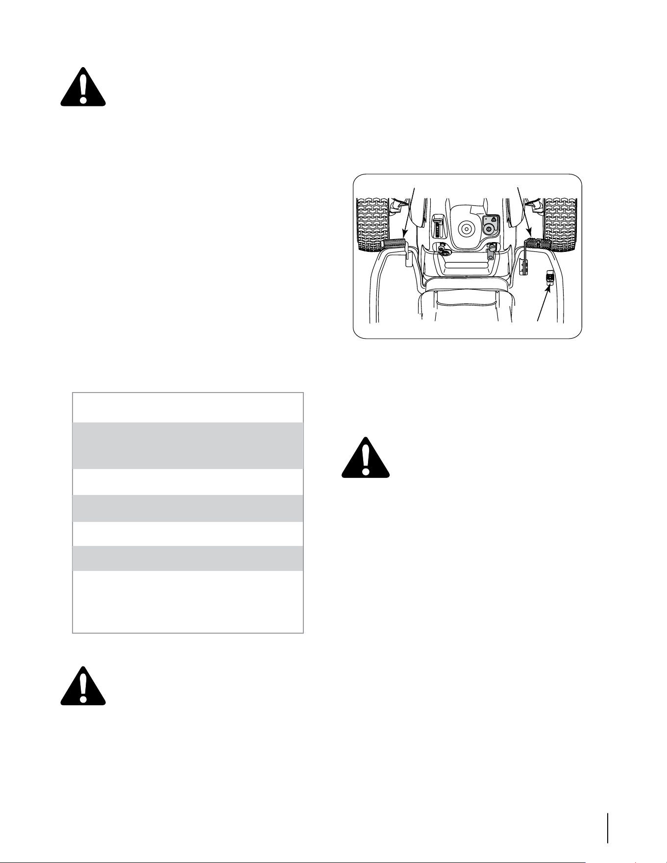
Driving The Tractor
IMPORTANT: Avoid sudden starts, excessive speed and
sudden stops.
Briefly depress the brake pedal to release the parking
brake. Move the throttle lever into the FAST (rabbit)
position.
To travel forward: Slowly depress the forward drive
control pedal until the desired speed is achieved. See
Figure 5-2.
Figure 5-2
To travel in reverse: Check that the area behind is clear,
then slowly depress the reverse drive control pedal until
the desired speed is achieved. See Figure 5-2.
Release the depressed drive pedal and depress the
brake pedal to stop the tractor.
WARNING! Do not leave the seat of the tractor
without first placing the PTO/Blade Engage
knob in the disengaged (OFF) position and
engaging the parking brake. If leaving the
tractor unattended, also turn the engine off
and remove the ignition key.
Steering the Tractor
Your i1000 series tractor is equipped with an innovative
steering system. Turning the steering wheel not only
turns the front wheels, but also adjusts the position of
the drive control linkage of the two hydro transmissions
that drive the tractor. This steering system allows you to
vary the radius of turns from a normal wide U-turn down
to a zero turn. Some practice may be needed to become
accustomed to the steering of your tractor. The steering
works as follows:
The steering wheel turns approximately two turns stop
to stop. With the center position being the straight
ahead position.
Minor turns of the steering wheel from the center
position (approximately 10º to 15º) turn only the front
axles and will result in wider turns.
Increasing the turn of the steering wheel (beyond 10°-
15º) results in increasingly tighter turns. As the steering
mechanism turns the front wheels, it also changes the
position of the transmission drive control linkage to
slow down the inner rear wheel in the turn, and adjust
the speed of the outer wheel as necessary to complete
•
•
•
•
•
•
•
IMPORTANT
Do not leave the seat of the tractor without
Disengaging PTO lever
Depressing brake pedal
Engaging parking brake
If leaving the tractor unattended, also turn the
ignition key off and remove the key.
Avoid sudden starts, excessive speed and sudden
stops while driving the tractor.
Do not mow on slope in excess of 15 degrees (a rise
of approximately 2-1/2 feet every 10 feet).
Keep hands and feet away from the opening of the
cutting deck.
Plan your mowing pattern to avoid discharge of
materials toward roads, sidewalks, bystanders and
the like. Also, avoid discharging material against a
wall or obstruction which may cause discharged
material to ricochet back toward the operator.
1.
2.
3.
Brake Pedal
Forward Drive Pedal
Reverse Drive Pedal
13sectiOn 5 — OperatiOn

the desired turn. Turn the steering wheel back to the
center position as the turn is completed.
NOTE: It is not necessary to release the drive pedal when
making a turn. The change to the transmission linkage
occurs regardless of how far the drive pedal is depressed.
When the steering wheel is straightened, the tractor will
return to the speed set by the drive pedal.
Turning the steering wheel fully to its stop in either
direction will fully turn the front wheels, reverse the
direction of the inner wheel and adjust the outer wheel
speed to execute a zero turn in the chosen direction.
Turn the steering wheel back to the center position as
the turn is completed.
NOTE: As the steering wheel is turned further toward
its stop, the effort needed to turn the steering wheel
increases.
IMPORTANT: Making tight or zero turns on grass will
greatly increase the potential for defacement of the turf.
Driving On Slopes
IMPORTANT: Refer to the SLOPE GAUGE on page 7 to
help determine slopes where you may operate the tractor
safely.
Mow up and down slopes, never across.
Watch for holes, ruts, bumps, rocks, or other hidden
objects. Uneven terrain could overturn the machine.
Tall grass can hide obstacles.
Avoid turns when driving on a slope. If a turn must
be made, turn downhill on the slope. Turning uphill
increases the possibility of a tractor rollover.
Avoid stopping when driving up a slope. If it is
necessary to stop while driving up a slope, start up
smoothly and carefully to reduce the possibility of
flipping the tractor over backward.
Engaging the Parking Brake
NOTE: The parking brake must be set if the operator
leaves the seat with the engine running or the engine will
automatically shut off.
To set the parking brake:
Press the brake pedal completely down with you right
foot and hold it that position.
Push the parking brake lever downward and hold it in
that position.
Remove your foot from the brake pedal.
Release pressure from the parking brake lever.
After completing step 3, the brake pedal should remain
in the down position. If it doesn’t, the parking brake is not
enaged. Repete steps 1-4 to engage the parking brake.
To disengage the parking brake, lightly press the brake
pedal .
WARNING: Never leave a running machine
unattended. Always disengage PTO, set parking
brake, stop engine and remove key to prevent
unintended starting
•
•
•
•
•
1.
2.
3.
4.
Engaging the PTO
Engaging the PTO transfers power to the cutting deck or
other (separately available) attachments. To engage the
PTO:
Move the throttle control lever to the FAST (rabbit)
position.
Pull the PTO/Blade Engage knob outward into the
engaged (ON) position.
NOTE: Always operate the tractor with the throttle lever
in the FAST (rabbit) position for the most efficient use of
the cutting deck or other (separately available) PTO driven
attachments.
Mowing
WARNING: To help avoid blade contact or a
thrown object injury, keep bystanders, helpers,
children and pets at least 75 feet from the
machine while it is in operation. Stop machine
if anyone enters the area.
This tractor is equipped with one of Cub Cadet’s high
quality cutting decks. The following information will be
helpful when using the cutting deck with your tractor.
Do not mow at high ground speed, especially if a mulch
kit or grass collector is installed.
For best results it is recommended that the first two laps be
cut with the discharge thrown towards the center. After the
first two laps, reverse the direction to throw the discharge
to the outside for the balance of cutting. This will give a
better appearance to the lawn.
Do not cut the grass too short. Short grass invites weed
growth and yellows quickly in dry weather.
Mowing should always be done with the engine at full
throttle.
Under heavier conditions it may be necessary to go back
over the cut area a second time to get a clean cut.
Do not attempt to mow heavy brush and weeds and
extremely tall grass. Your tractor is designed to mow
lawns, not clear brush.
Keep the blades sharp and replace the blades when
worn. Refer to the “SERVICE” section of this manual for
proper blade sharpening instructions.
IMPORTANT: When stopping the tractor for any reason
while on a grass surface, always
Place the shift lever in neutral,
Engage the parking brake,
Shut engine off and remove the key.
Doing so will minimize the possibility of having your lawn
‘‘browned’’ by hot exhaust from your tractor’s running
engine.
1.
2.
•
•
•
•
•
•
•
•
•
•
14 sectiOn 5— OperatiOn
Maintenance & Adjustments
6
15
Maintenance
WARNING! Before performing any mainte-
nance or repairs, disengage the PTO, move the
drive control levers fully outward in the neutral
position, engage the parking brake, stop the
engine and remove the key to prevent unin-
tended starting.
Engine
Refer to the Kohler Owner’s Manual for all engine main-
tenance intervals, procedures, specifications and instruc-
tions.
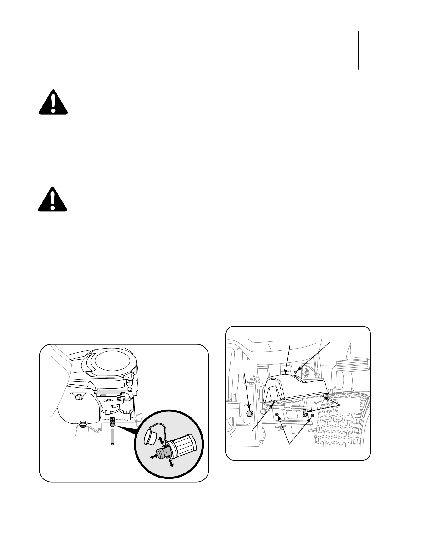
Changing the Engine Oil
WARNING! If the engine has been recently run,
the engine, muffler and surrounding metal
surfaces will be hot and can cause burns to the
skin. Exercise caution to avoid burns.
To complete an oil change, proceed as follows:
Run the engine for a short time to warm the engine
oil. The oil will flow more freely and carry away more
impurities. Use care to avoid burns from hot oil.
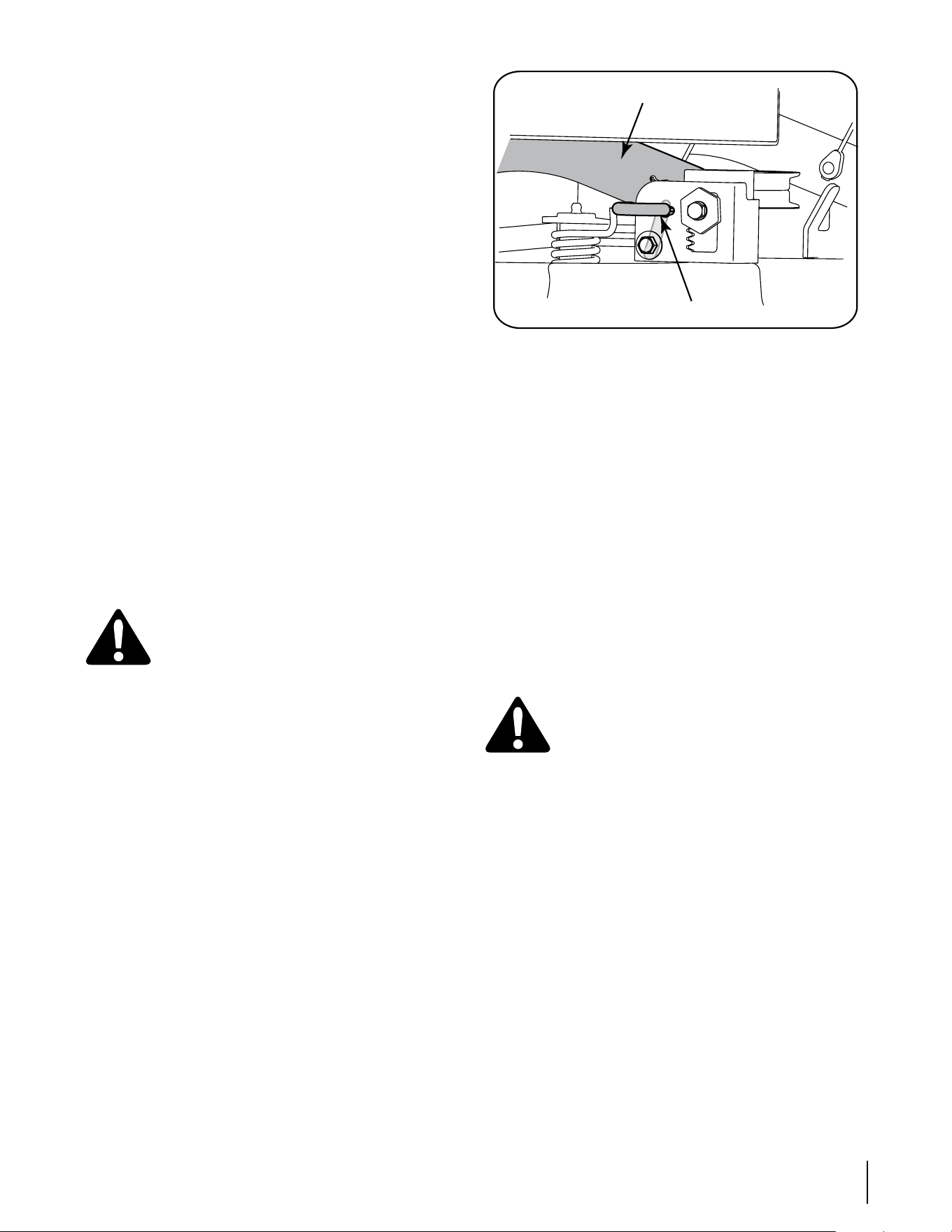
Locate the oil drain port on the left side of the engine.
Pop open the protective cap on the end of the oil drain
valve to expose the drain port. Refer to Figure 6-1.
Remove the oil fill cap/dipstick from the oil fill tube.
Push the oil drain hose (packed with this manual) onto
the oil drain port. Route the opposite end of the hose
into an appropriate oil collection container with at least
a 2.0 quart capacity, to collect the used oil.
Pinch the tabs on the oil drain valve, then pull outward
to begin draining oil. See Fig 6-1.
Figure 6-1
1.
2.
3.
4.
5.
After the oil has finished draining, push the end of
the oil drain valve back in, until the tabs click into
place. Re-cap the end of the oil drain valve to keep
debris from entering the drain port.
Replace the oil filter, and refill the engine with new
oil as instructed in the Kohler Owner’s Manual.
Air Cleaner
Service the pre-cleaner and cartridge/air cleaner ele-
ment as instructed in the Kohler Owner’s Manual.
Spark Plug
The spark plugs should be cleaned and the gap reset
once a season. Refer to the Kohler Owner’s Manual for
correct plug type and gap specifications.
Hydrostatic Transmission
The zero turn tractor is equipped with dual integrated
hydrostatic pumps/transaxles that are sealed and are
maintenance-free. Fluid levels cannot be checked and
fluid cannot be added or changed.
Steering Lubrication
The steering arms, pivot shafts, and axles must be
lubricated if ever the steering effort increases, or after
every 25 hour of operation. Lubricate using a pressure
grease gun and Cub Cadet 251H EP grease, or an
equivalent No. 2 multipurpose lithium grease.
Apply grease through the lube fitting on the RH
and LH steering arms which are located at rearward
end of the two steering drag links. See Figure 6-2.
Figure 6-2
Locate the lube fittings for the pivot shaft and axle
on the front of one end of the axle pivot bar. Apply
grease through the two lube fittings, then repeat to
lubricate the other end of the pivot bar. See Figure
6-2.
6.
7.
•
•
Axle Pivot Bar
lube Fittings
Shoulder
Bolt
Hex
Screw
Steering
Gear Cover
Cover
Tab
Steering Arm
lube Fitting
16 sectiOn 6— Maintenance & adjustMents
Cleaning Steering Gears
Once a year, or if a tight spot is experienced when turning
the steering wheel, remove the steering gear cover on
each end of the pivot bar and clean the two steering gears.
From beneath the cover base plate on each end of the
pivot bar, remove the three hex screws securing the
steering gear cover. Remove the covers and clean the
gears. It is not necessary to lubricate the gears. Refer to
Figure 6-2.
Insert the tab of the LH steering gear cover into the
square hole in the LH base plate, position the cover, and
secure with the three hex screws. Do not over tighten.
Repeat to install the cover on the RH side.
Lubricate Front Wheel Bearings
Lubricate the front wheel bearings with Cub Cadet 251H EP
grease after every 25 hours of operation. The lube fittings
are located in the rim hub inside each front wheel.
Lubricate Deck Spindles and Idler Bracket
Lubricate the deck spindles and idler bracket with Cub
Cadet 251H EP grease after every 10 hours of operation.
The deck spindle lube fittings are in the spindle housings,
and can only be accessed from the underside of the deck.
Lubricate the idler bracket through the lube fitting in the
top of the shoulder bolt. Use a pressure grease gun to
lubricate the spindles and idler bracket.
Lubricate Pivot Points & Linkage
Lubricate all the pivot points on the drive system, parking
brake and lift linkage at least once a season with light oil.
Lubricate Rear Wheels
The rear wheels should be removed from the axles once
a season. Lubricate the axles and the rims well with an all-
purpose grease before re-installing them.
Tires
WARNING: Never exceed the maximum
inflation pressure shown on the sidewall of
tire. Refer to the tire sidewall for exact tire
manufacturer’s recommended or maximum psi.
Do not overinflate.
The recommended operating tire pressure is:
Approximately 10 psi for the rear tires
Approximately 14 psi for the front tires
IMPORTANT: Uneven tire pressure could cause the cutting
deck to mow unevenly.
Cleaning the Tractor and Deck
Any fuel or oil spilled on the machine should be wiped off
promptly. Do NOT allow debris to accumulate around the
deck pulleys or any other part of the machine.
Periodically remove the belt covers and remove any ac-
cumulated grass clippings from around the spindle pulleys
and the deck belt.
IMPORTANT: The use of a pressure washer to clean your
tractor is NOT recommended. It may cause damage to
electrical components, spindles, pulleys, bearings or the
engine.
•
•
•
•
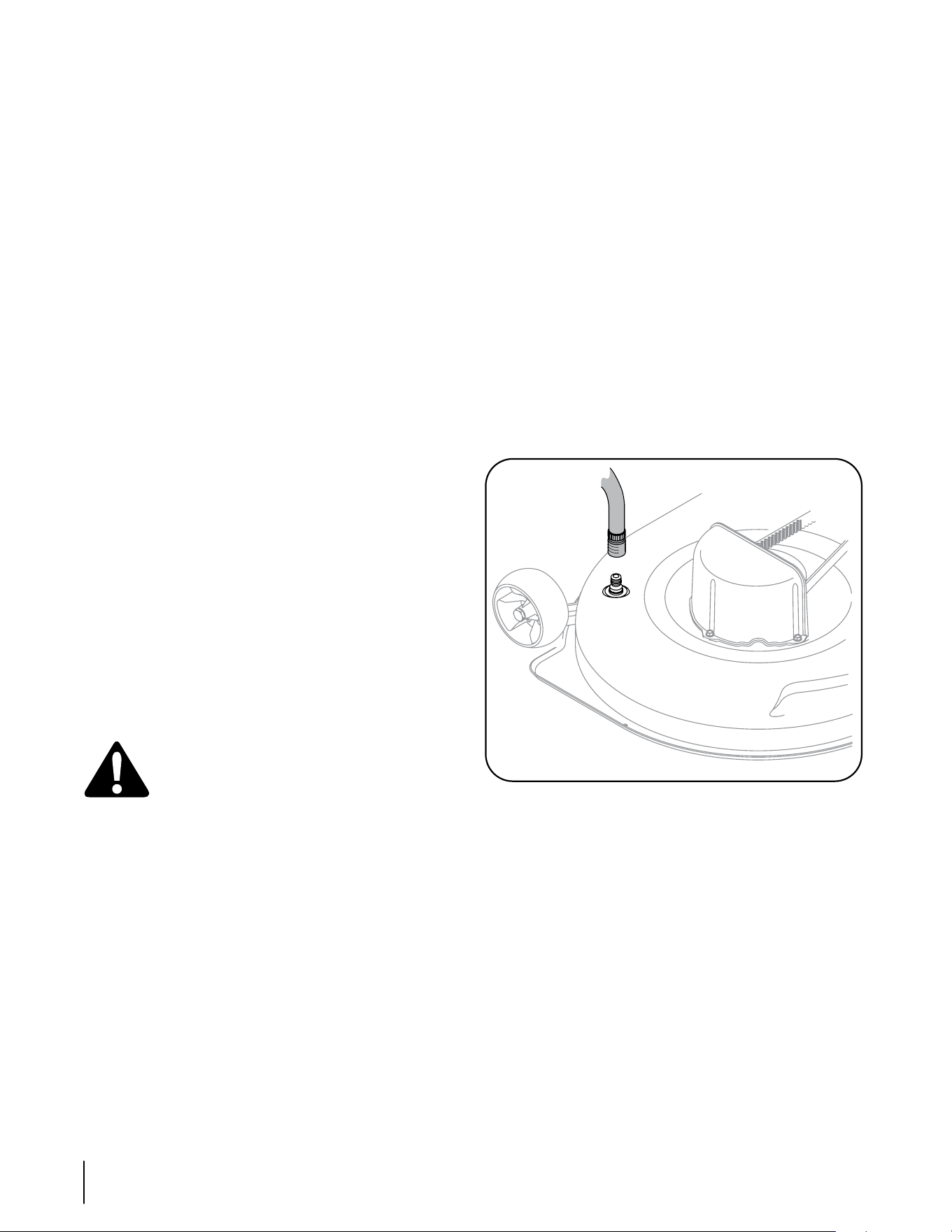
Using Deck Wash System™
Use the Deck Wash System™ to rinse grass clippings from
the deck’s underside and prevent the buildup of corrosive
chemicals. Your tractor’s deck is equipped with a water
nozzle on the left end of the deck.
Complete the following steps AFTER EACH MOWING:
1. Drive the tractor to a level, clear spot on your lawn, near
enough to a water sillcock (spigot) for your garden hose
to reach.
IMPORTANT: Make certain the tractor’s discharge chute is
directed AWAY from your house, garage, parked cars, etc.
2. Disengage the PTO (Blade Engage), set the parking
brake, and stop the engine.
3. Thread the nozzle adapter (packaged with your tractor’s
Operator’s Manual) onto the end of your garden hose.
4. Pull back the lock collar of the nozzle adapter and push
the adapter onto the deck wash nozzle at the left end
of the mower deck. Release the lock collar to lock the
adapter on the nozzle. See Figure 21.
Figure 6-3
5. Turn the water on.
6. While sitting in the operator’s position on the tractor,
re-start the engine and place the throttle lever in the
FAST (rabbit) position.
7. Move the tractor’s PTO (Blade Engage) into the ON posi-
tion. Remain in the operator’s position with the cutting
deck engaged for a minimum of two minutes, allowing
the underside of the cutting deck to thoroughly rinse.
8. Move the tractor’s PTO (Blade Engage) into the OFF
position. Turn the ignition key to the STOP position to
turn the tractor’s engine off.
9. Pull back the lock collar of the nozzle adapter to discon-
nect the adapter from the nozzle.
17sectiOn 6 — Maintenance & adjustMents
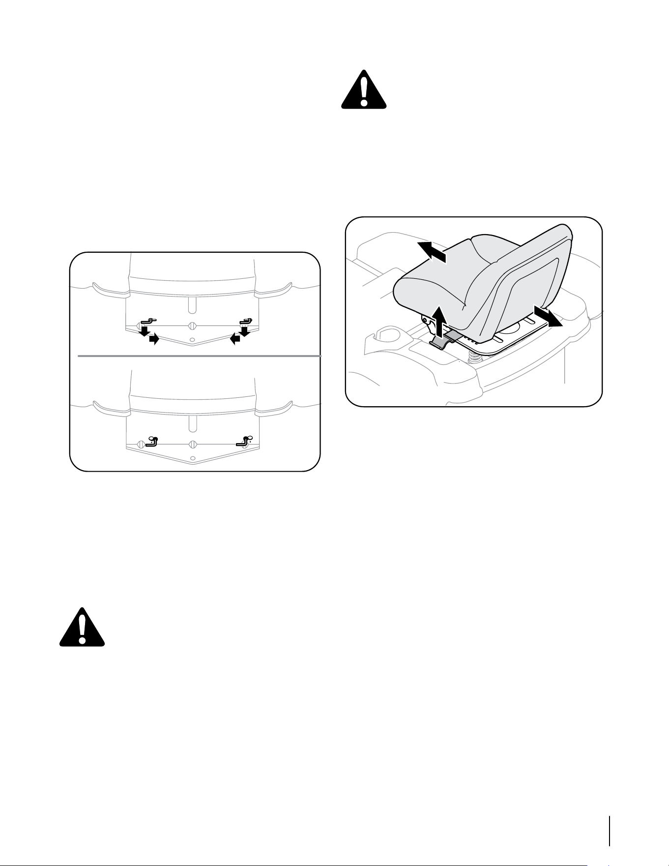
Adjusting the Seat
WARNING: After adjusting the seat or before
driving the tractor, make sure that the seat
adjustment lever is engaged in the seat index
plate and that the seat will not move. Do not
adjust the seat while the tractor is being driven.
Adjusting the seat while the tractor is moving
could cause the operator to lose control of the
tractor.
While sitting in the seat, grasp the seat adjustment
lever on the left side of the seat and pull it upward to
disengage from the seat index plate. See Figure 6-5.
Figure 6-5
Slide the seat to the desired position. See Figure 6-5.
Once the desired position is reached, release the seat
lever. Slide the seat slightly fore and aft as necessary to
engage the seat lever into one of the eight adjustment
positions in the index plate. Make certain the seat is
locked in position.
Side to Side Leveling the Deck
NOTE: Check the tractor’s tire pressure before performing
any deck leveling adjustments. Refer to “Tires” earlier in
this section for information regarding tire pressure.
If the cutting deck appears to be mowing unevenly, a side
to side adjustment can be performed. Adjust if necessary
as follows:
With the tractor parked on a firm, level surface, move
the deck to the mid height position (third or fourth
notch) using the deck lift lever. Rotate the left blade so
that it is perpendicular to the tractor frame. Measure
and record the distance from the outside of the left
blade tip to the ground.
Moving to the other side of the tractor, rotate the right
blade so that it is perpendicular to the tractor frame,
and measure the distance from its outer blade tip to
the ground.
Both measurements taken should be equal. If they’re
not, note whether the left side of the deck is lower or
higher and proceed to the next step.
1.
2.
3.
1.
2.
3.
Moving the Tractor Manually
If for any reason the tractor will not drive or you wish to
move the tractor, engage the two hydro transmission
bypass rods to manually move the tractor short distances.
IMPORTANT: Never tow or drag the tractor with the rear
wheels on the ground. Even with the bypass rods engaged.
Doing so will damage the transmissions.
To engage a bypass rod, pull the rod rearward so that the
flange on the rod passes through the larger/rounded part
of the keyhole slot. With the flange of the rod outside
(rearward) of the hitch plate, push the rod inward in the
small part of the keyhole slot so that rod’s flange is locked
against the back of the hitch plate. Repeat to engage
the other bypass rod to allow the tractor to be manually
moved. See Figure 6-4.
Figure 6-4
To disengage, move the rod to align its flange with the
larger/rounded part of the keyhole slot and release the rod
back through the hitch plate.
NOTE: The transmission will NOT engage when the hydro-
static bypass rod is pulled out. Return the rod to its normal
position prior to operating the tractor.
Adjustments
WARNING: Never attempt to make any adjust-
ments while the engine is running, except
where specified in the operator’s manual. Dis-
connect spark plug wire(s) before performing
any adjustments, repairs or maintenance.
Steering and Transmission Linkage
The steering tie rod and drag links and the related
transmission linkage are set at the factory and should
not require further adjustment. Because of the complex
adjustment procedure, the steering and transmission
linkage should only be serviced or adjusted by a qualified
mechanic. If you experience problems with steering, or
with the hydro drive transmissions, contact your nearest
Cub Cadet dealer to have the tractor inspected.
18 sectiOn 6— Maintenance & adjustMents
Working from the left side of the tractor, loosen, but do
not remove, the hex cap screw in the left deck adjust-
ment bracket. See Figure 6-6.
Figure 6-6
To even the deck turn the adjustment gear, located
immediately behind the hex cap screw, clockwise (rear-
ward) to lower the left side of the deck. Turn the gear
counter-clockwise (toward front) to raise the left side of
the deck. See Figure 6-6.
The deck is properly leveled when both blade tip mea-
surements, as described earlier, are equal.
Retighten the hex cap screw in the left deck adjust-
ment bracket when proper adjustment is achieved.
Front To Rear Deck Leveling
The front of the cutting deck is supported by an adjustable
front deck hanger rod. This rod can be adjusted to set the
front to rear pitch of the deck. The front of the deck should
be approximately 1/4-inch lower than the rear of the deck.
Adjust if necessary as follows:
NOTE: The deck should first be leveled side to side. Check
the side to side level of the deck and adjust if necessary.
With the tractor parked on a firm, level surface, move
the deck to the mid height position (third or fourth
notch) using the deck lift lever. Carefully rotate the RH
blade (nearest the discharge chute) so that it is parallel
with the tractor frame.
Measure the distance from the front of the blade tip to
the ground and the rear of the blade tip to the ground.
The front measurement taken should be approximately
1/4” less than the rear measurement. Determine wheth-
er the front of the deck has to be raised or lowered.
Working at the front of the tractor, loosen the two hex
lock nuts at the front of the deck hanger rod. Thread
the lock nuts away from the hex nuts behind them.
Refer to Figure 6-7.
Use a open end wrench to turn the inner hex nuts to
adjust the front of the deck. Turn the hex nuts clock-
wise to raise the front of the deck, or counterclockwise
to lower the front of the deck. Adjust the hex nuts
evenly so that the deck hanger rod is at the front of
both slots in the hanger bracket on the front of the
deck. See Figure 6-7.
Retighten the two hex lock nuts when properly
adjusted.
4.
5.
6.
7.
1.
2.
3.
4.
5.
Figure 6-7
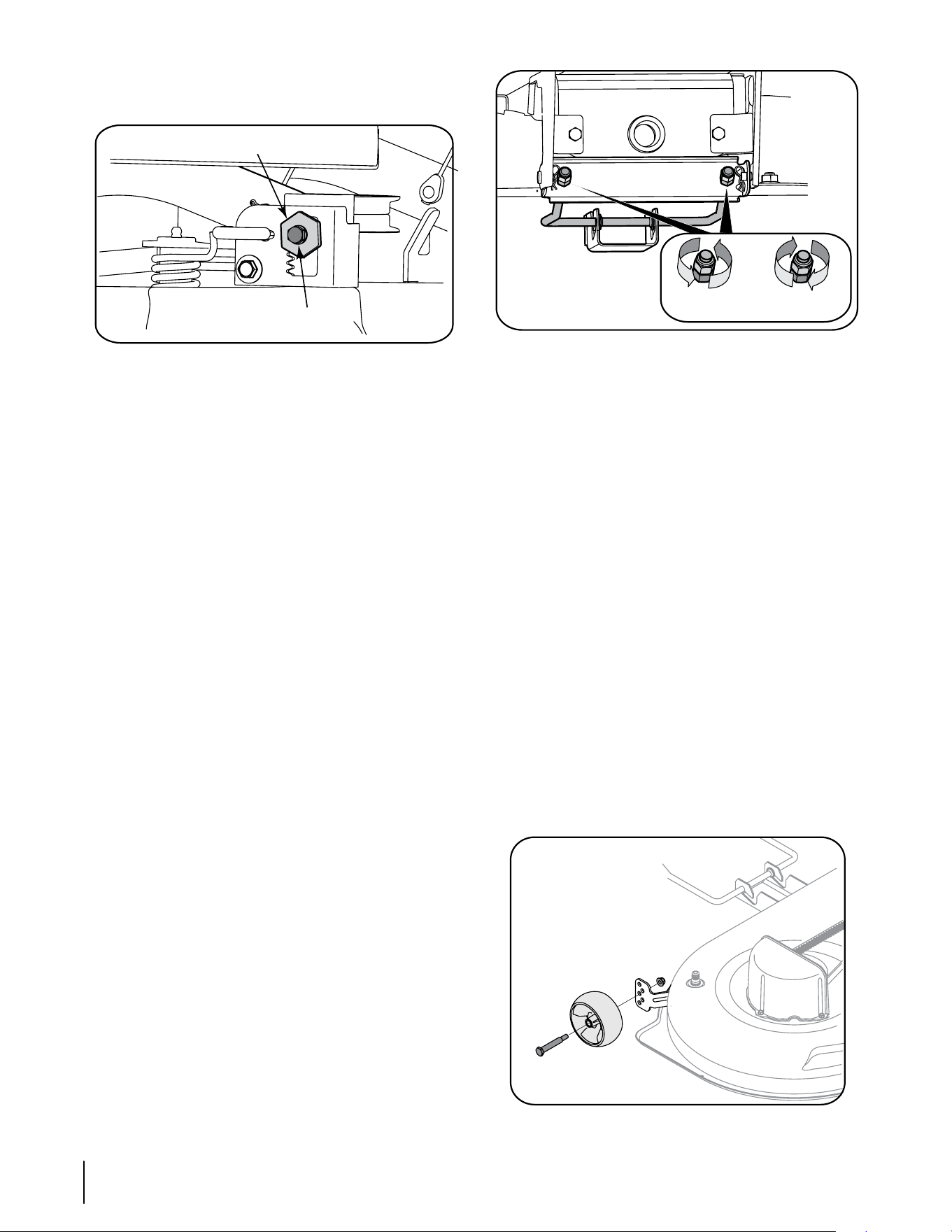
Deck Gauge Wheel Adjustment
NOTE: The deck gauge wheels are an anti-scalp feature
of the deck and are not designed to support the weight of
the cutting deck.
The deck gauge wheels should neither contact the ground,
nor be high off the ground, when the deck is moved to the
desired height setting. If you change your cutting height
during the mowing season, the gauge wheels should be
checked and adjusted as necessary. Adjust the gauge
wheels as follows:
• Place the tractor on a flat surface and move the deck to
the desired mowing height using the deck lift lever.
• Check gauge wheels distance from the flat surface
below. If the gauge wheels contact the ground, they
must be raised. If the gauge wheels are higher than 1/2"
above the ground, they should be lowered.
• Remove the hex flange lock nut and shoulder bolt
securing one of the front ball wheels to the front index
bracket. Reposition the ball wheel to align with the one
of five index holes that places the wheel 1/4" to 1/2"
above the ground. Secure the ball wheel to the index
bracket with the shoulder bolt and flange lock nut. Note
the index hole used and secure the other ball wheel in
the same position. See Figure 6-8.
Figure 6-8
Raise Front
of Deck
Lower Front
of Deck
Adjustment Gear
Hex Cap Screw

19sectiOn 6 — Maintenance & adjustMents
Maintenance Schedule
Before
Each use
Every
10 Hours
Every
25 Hours
Every
50 Hours
Every
100 Hours
Prior
to Storing
Clean Hood/Dash Louvers
P P
Check Engine Oil Level
P
Check Air Filter for Dirty, Loose or Damaged Parts
P
Clean and Re-oil Air Filter’s Foam Precleaner
P
Replace Air Filter Element
P
Change Engine Oil and Replace Oil Filter
P
Clean Battery Terminals
P P
Lube Mid Steering Arms, Pivot Shafts, and Axles
P P
Lube Front Wheel Bearings
P P
Clean Engine Cooling Fins
P P
Lube Front Deck Wheels
P P
Lube Deck Spindles and Idler Bracket
P P
Lube Pedal Pivot Points
P
Check Spark Plug Condition & Gap
P P
Replace Fuel Filter
P

Service
7
20
Pivot Bar adjustment
If excessive play is experienced in the steering wheel,
check the pivot bar for forward/rearward movement.
Raise the front of the tractor and set it on jack stands,
so the front wheels are suspended above the ground.
Grasping the ends of the pivot bar, attempt to move
each end of the axle forward and rearward to check for
side play. There should be minimal or no side play.
If there is no side play, lower the tractor to the ground
and have the steering linkage inspected by you Cub
Cadet dealer. If there is side play, tighten the pivot bar
as follows:
Support the pivot bar, then remove the hex lock
nuts securing the two shoulder bolts that pass
through the pivot bar bracket, the pivot bar, and
frame. Refer to Figure 6-2.
Slide a half inch flat washer, with a maximum thick-
ness of .030 inch, onto each shoulder bolt. Reinstall
the shoulder bolts w/washers and fasten with the
two hex lock nuts.
Gradually and evenly tighten the hex lock nut while
continuing to check the forward/rearward move-
ment of the pivot bar. Tighten the lock nuts until
minimum play, without binding the pivot bar’s up
and down movement, is achieved.
Checking Main Harness Fuse
A 20 amp fuse is installed in your tractor’s wiring
harness to protect the tractor’s electrical system from
damage caused by excessive amperage.
If the electrical system does not function, or your
tractor’s engine will not crank, first check to be certain
that the fuse has not blown.
The fuse can be found inside of the dash panel behind
the battery tray. You may need to remove the battery
to gain access to the fuse. Always use a fuse with the
same amperage capacity for replacement.
NOTE: A second fuse holder can be found inside the dash
panel. This fuse holder is used for the optional 12 volt
power outlet.
Battery
The battery is sealed and is maintenance-free. Acid levels
cannot be checked.
Always keep the battery cables and terminals clean and
free of corrosive build-up.
After cleaning the battery and terminals, apply a light
coat of petroleum jelly or grease to both terminals.
Always keep the rubber boot positioned over the posi-
tive terminal to prevent shorting.
1.
2.
3.
•
•
•
•
•
•
•
•
•
IMPORTANT: If removing the battery for any reason, discon-
nect the NEGATIVE (Black) wire from it’s terminal FIRST,
followed by the POSITIVE (Red) wire. When re-installing the
battery, always connect the POSITIVE (Red) wire its terminal
first, followed by the NEGATIVE (Black) wire. Be certain that
the wires are connected to the correct terminals; reversing
them could change the polarity and result in damage to
your engine’s alternating system.
Charging the Battery
If the tractor has not been put into use for an extended pe-
riod of time, charge the battery with an automotive-type
12-volt charger for a minimum of one hour at six amps.
WARNING: Batteries give off an explosive gas
while charging. Charge battery in a well venti-
lated area and keep away from an open flame
or pilot light as on a water heater, space heater,
furnace, clothes dryer or other gas appliances.
Cleaning the Battery
Clean the battery by removing it from the tractor and
washing with a baking soda and water solution. If neces-
sary, scrape the battery terminals with a wire brush to
remove deposits. Coat terminals and exposed wiring with
grease or petroleum jelly to prevent corrosion.
Battery Failures
Some common causes for battery failure are:
• incorrect initial activation • undercharging
• overcharging • corroded connections
• freezing
These failures are NOT covered by your tractor’s warranty.
Changing Transmission Drive Belt
NOTE: Several components must be removed, including
transmission steering linkage which will have to be read-
justed, in order to change the tractor’s transmission drive
belt. Contact your Cub Cadet dealer to have your transmis-
sion drive belt replaced.
Hydrostatic Transmission
Keep the area around the transmission cooling fan free of
grass and debris at all times. The hydrostatic transmission
is sealed at the factory and is maintenance free. The fluid
level cannot be checked and cannot be changed.
Off Season Storage
If the machine is to be inoperative for a period longer than
30 days, the following procedures are recommended:
WARNING: Never store the machine or fuel
container indoors where there is an open flame,
spark or pilot light such as on water heater,
furnace, clothes dryer or other gas appliance.
21sectiOn 7 — service
IMPORTANT: Fuel left in the fuel tank during warm weath-
er deteriorates and will cause serious starting problems.
To prevent gum deposits from forming inside the engine’s
carburetor and causing possible malfunction of the en-
gine, the fuel system must be either completely emptied,
or the gasoline must be treated with a stabilizer to prevent
deterioration.
If using a fuel stabilizer:
Read the product manufacturer’s instructions and
recommendations.
Add to clean, fresh gasoline the correct amount of
stabilizer for the capacity of the fuel system.
Fill the fuel tank with treated fuel and run the
engine for 2-3 minutes to get stabilized fuel into the
carburetor.
If emptying the fuel system:
Do not drain fuel when the engine is hot. Allow the
engine adequate time to cool. Drain fuel into an ap-
proved container outdoors, away from open flame.
Drain any large volume of fuel from the tank by
disconnecting the fuel line from the in-line fuel filter
near the engine.
Reconnect the fuel line and run the engine until
it starts to falter, then use the choke to keep the
engine running until all fuel in the carburetor has
been exhausted.
Again disconnect the fuel line and drain any remain-
ing gasoline from the system.
WARNING: Drain fuel only into an approved
container outdoors, away from an open flame.
Allow engine to cool. Extinguish cigarettes,
cigars, pipes, and other sources of ignition prior
to draining fuel.
Remove the spark plug and pour one (1) ounce of engine
oil through the spark plug hole into the cylinder. Crank the
engine several times to distribute the oil. Replace the spark
plug.
Before storing for an extended period, clean and lubricate
the tractor as instructed in “Maintenance and Adjustments.”
Cutting Deck Removal
To remove the cutting deck, proceed as follows:
Disengage the PTO (Blade Engage) and engage the
parking brake.
Place the deck gauge wheels in their highest setting
(lowest deck setting).
Lower the deck by moving the deck lift lever into the
bottom notch on the right fender.
Looking at the cutting deck from the left side of the
tractor, locate the deck support pin on the rear left side
of the deck. Refer to Figure 7-1.
Pull the deck support pin outward to release the deck
from the deck lift arm. Pivot the support pin handle
downward to lock the pin in the disengaged position.
Refer to Figure 7-1.
Move to the right side of the tractor and repeat the
previous step to release the deck from the RH lift arm.
1.
•
•
•
2.
•
•
•
•
1.
2.
3.
4.
5.
6.
Figure 7-1
Move the deck lift lever into the top notch on the right
fender to raise deck lift arms up and out of the way.
Carefully slide the cutting deck forward until the front
deck hanger rod can be removed from the slots of the
hanger bracket at the front of the deck.
The PTO belt is captured inside the PTO pulley on the
bottom of the engine by a belt keeper. From beneath
the front/left side of the tractor, locate the hex tapping
screw securing the left side of the belt keeper to the
bottom of the tractor frame. After first noting the frame
hole into which right side of the belt keeper is inserted,
remove the hex tapping screw and belt keeper. Slide
the PTO belt off the tractor’s PTO pulley.
While holding the front deck hanger rod upward to
clear the deck front hanger bracket, carefully slide the
deck out from the right side of the tractor.
Cutting Blades
WARNING: Be sure to shut the engine off,
remove ignition key, disconnect the spark plug
wire(s) to prevent unintended starting before
removing the cutting blade(s) for sharpening or
replacement. Protect your hands by using heavy
gloves or a rag to grasp the cutting blade.
The blades may be removed as follows.
Remove the deck from beneath the tractor, (refer to
Cutting Deck Removal) then gently flip the deck over to
expose its underside.
NOTE: A block of wood may be placed between the deck
housing and the cutting edge of the blade to help in
breaking loose the hex nut securing the blade.
Use a 15/16" wrench to loosen the hex flange nut securing
the blade to the bottom of the spindle assembly. Secure
the spindle by either holding the blade tightly, or by using
a second wrench to hold the nut at the top of the spindle.
Continue holding the blade onto the star hub of the
spindle, and remove the flange nut and cutting blade.
Repeat the previous steps to remove the other blade.
To properly sharpen the cutting blades, remove equal
amounts of metal from both ends of the blades along
the cutting edges, parallel to the trailing edge, at a 25°
to 30° angle.
6.
7.
8.
9.
•
•
•
•
•
Deck Support Pin
Deck Lift Arm
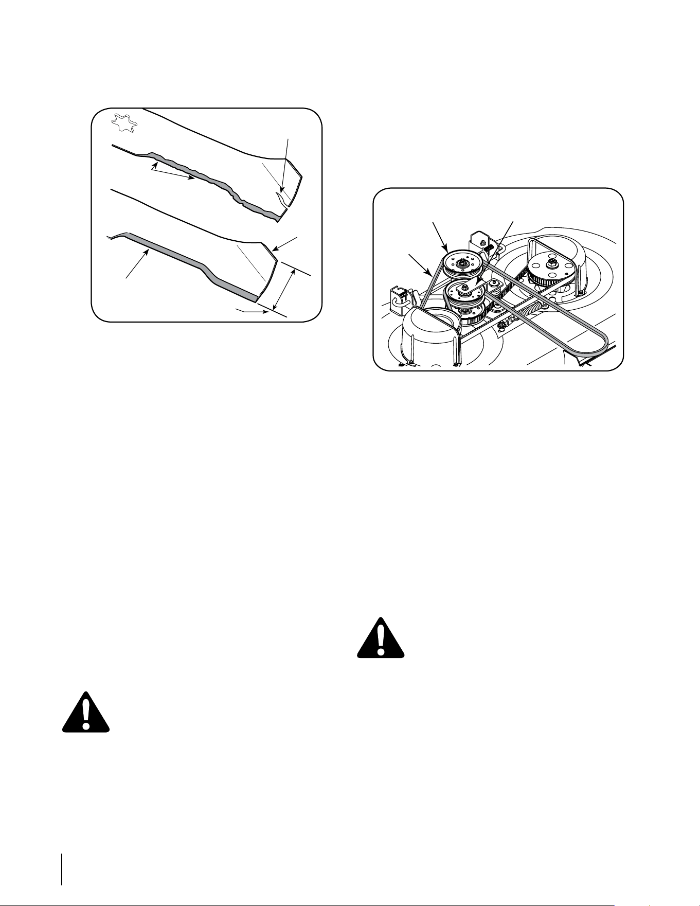
22 sectiOn 7— service
IMPORTANT: If the cutting edge of the blade has already
been sharpened to within 1 5/8” from the edge, or if any
metal separation is present, replace the blades with new
ones. See Figure 7-2.
Figure 7-2
It is important that each cutting blade edge be ground
equally to maintain proper blade balance.
A poorly balanced blade will cause excessive vibration
and may cause damage to the tractor and result in per-
sonal injury. The blade can be tested by balancing it on
a round shaft screwdriver. Grind metal from the heavy
side until it balances evenly.
IMPORTANT: When replacing the blades, make certain the
side of the blade marked ‘‘Bottom’’ faces the ground when
the mower is turned to the operating position.
IMPORTANT: Note that the stars of the blades (and spin-
dles) are not symmetrical. The blade can be installed on
each spindle in only one direction. Carefully align the star
hole of the blade with the star of the spindle shaft when
installing each blade. DO NOT improperly align the blade
and spindle shaft, and attempt to seat the blade onto the
spindle by tightening the hex flange nut.
Rotate the blade as necessary to align its star hole
with the star of the spindle shaft, then slide the blade
onto the spindle shaft. Thread the hex flange onto the
spindle shaft and use a torque wrench to tighten the
hex flange nut to 70 to 90 foot-pounds.
Repeat the above procedure to install the other blade.
Changing the PTO Belt
WARNING: Be sure to shut the engine off,
remove ignition key, disconnect the spark plug
wire(s) to prevent unintended starting before
removing the belt(s).
All belts on your tractor are subject to wear and should be
replaced if any signs of wear are present.
IMPORTANT: Do not use substitute belts. The V-belt found
on your tractor is specially designed for optimal perfor-
mance and service life for your deck application. Use only
OEM original replacement belts.
•
•
•
•
To replace the PTO belt, proceed as follows:
Remove the deck from beneath the tractor (refer to Cut-
ting Deck Removal).
Maneuver the PTO belt downward and off the idler
pulley on the spring loaded idler bracket. NOTE: It may
be necessary to loosen the hex cap screw and flange
lock nut securing the pulley to the idler bracket to fit
the belt between the pulley and bracket. Slide the belt
between the bottom of the idler pulley and top of the
timing belt idler pulley below. See Figure 7-3.
Figure 7-3
Loop the belt and push out of the V- groove of the drive
pulley on the right hand spindle assembly. Lift the belt
over the pulley and out from beneath the spindle cover.
See Figure 7-3.
Loop the new PTO belt and slide between the top of
the drive pulley and spindle cover. Maneuver the belt
around and into the V-groove of the drive pulley.
Route the back side of the belt around idler pulley and
between the idler pulley and idler bracket. Re-tighten
the hex screw and flange lock nut if loosened earlier.
Refer to Figure 7-3.
Route the belt around the fixed idler pulley as shown
in Figure 7-3 and re-install the deck as described in “Re-
installing the Cutting Deck” later in this section.
Changing the Timing Belt
WARNING: Be sure to shut the engine off,
remove ignition key, disconnect the spark plug
wire(s) to prevent unintended starting before
removing the belt(s).
To replace the timing belt, proceed as follows:
Remove the deck from beneath the tractor (refer to Cut-
ting Deck Removal).
Remove the PTO belt drive pulley of the right hand
spindle assembly as described in “Changing the PTO
Belt.”
Remove the hex screw, flat washer, lock washer, shoul-
der spacer, and flange lock nut that make up the idler
bracket backstop. NOTE: It may be necessary to clean
the underside of the mowing deck to access the hex
screw. Refer to Figure 7-4.
•
•
•
•
•
•
•
•
•
1-5/8 inch
Blade Separation
Worn Blade
Edge
Sharpen Edge
Evenly
Wind Wing
Idler Bracket
and Pulley
Fixed Idler
Pulley
PTO Belt
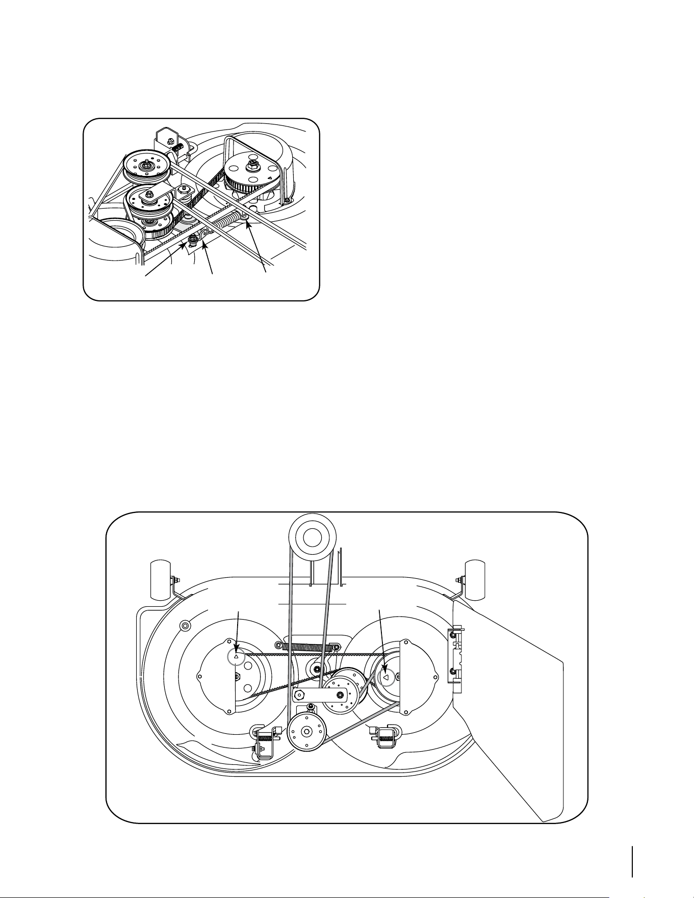
23sectiOn 7 — service
Applying force to either the timing belt idler pulley or
the timing belt idler bracket, pivot and hold the idler
bracket against the spring tension just far enough to
allow lifting the timing belt off and above the idler pul-
ley. Carefully release the idler bracket. See Figure 7-4.
Figure 7-4
Loop the timing belt and lift out of the timing pulley
and over the right hand spindle assembly. Maneuver
the belt between the drive pulley on top of the spindle
assembly and the spindle cover to remove.
Repeat the above procedure to remove the belt from
the left hand spindle assembly timing pulley. Refer to
Figure 7-4.
Loop the new timing belt and maneuver the belt be-
tween the drive pulley on top of the right hand spindle
assembly and the spindle cover. Lower the belt until
loosely around the right hand timing pulley. Refer to
Figure 7-4.
•
•
•
•
Idler Bracket &
Bracket
Backstop
Spring &
Screw
Idler Pulley
Note the arrows on the top of the timing pulley on the
LH spindle and on the drive pulley of the RH spindle
assembly. These timing arrows MUST be positioned 90°
from each other as shown in Figure 7-5.
Rotate the RH spindle assembly to position the drive
pulley timing arrow as shown in Figure 7-5. Then with-
out moving the RH drive pulley, pull the timing belt
tight against the RH timing pulley, above the timing
belt idler pulley, and over to the LH timing pulley.
Turn the LH timing pulley so that its timing arrow is 90°
from the RH spindle assembly timing arrow. Refer to
Figure 7-5.
While making sure not to change the position of either
pulley, loop the timing belt over the LH timing pulley.
After making sure the spring is hooked onto the idler
bracket and screw, pivot the timing idler bracket/idler
pulley against the spring tension just far enough to
allow you to lower the backside of the timing belt onto
the idler pulley. See Figure 7-5.
Re-check the timing arrows on the two pulleys. If they
have moved from the 90º position when tensioning the
timing belt, pivot the idler pulley to relieve tension on
the belt and re-position the pulleys. The timing arrows
MUST be positioned 90° from each other as shown
in Figure 7-5.
Re-install the idler bracket backstop components as
originally installed in the deck housing, and position so
that there is a 1/8" gap between the backstop and idler
bracket. Tighten the hex screw and flange lock nut to
secure in the adjusted position.
•
•
•
•
•
•
•
Drive Pulley
Timing Arrow
Timing Pulley
Timing Arrow
Figure 7-5
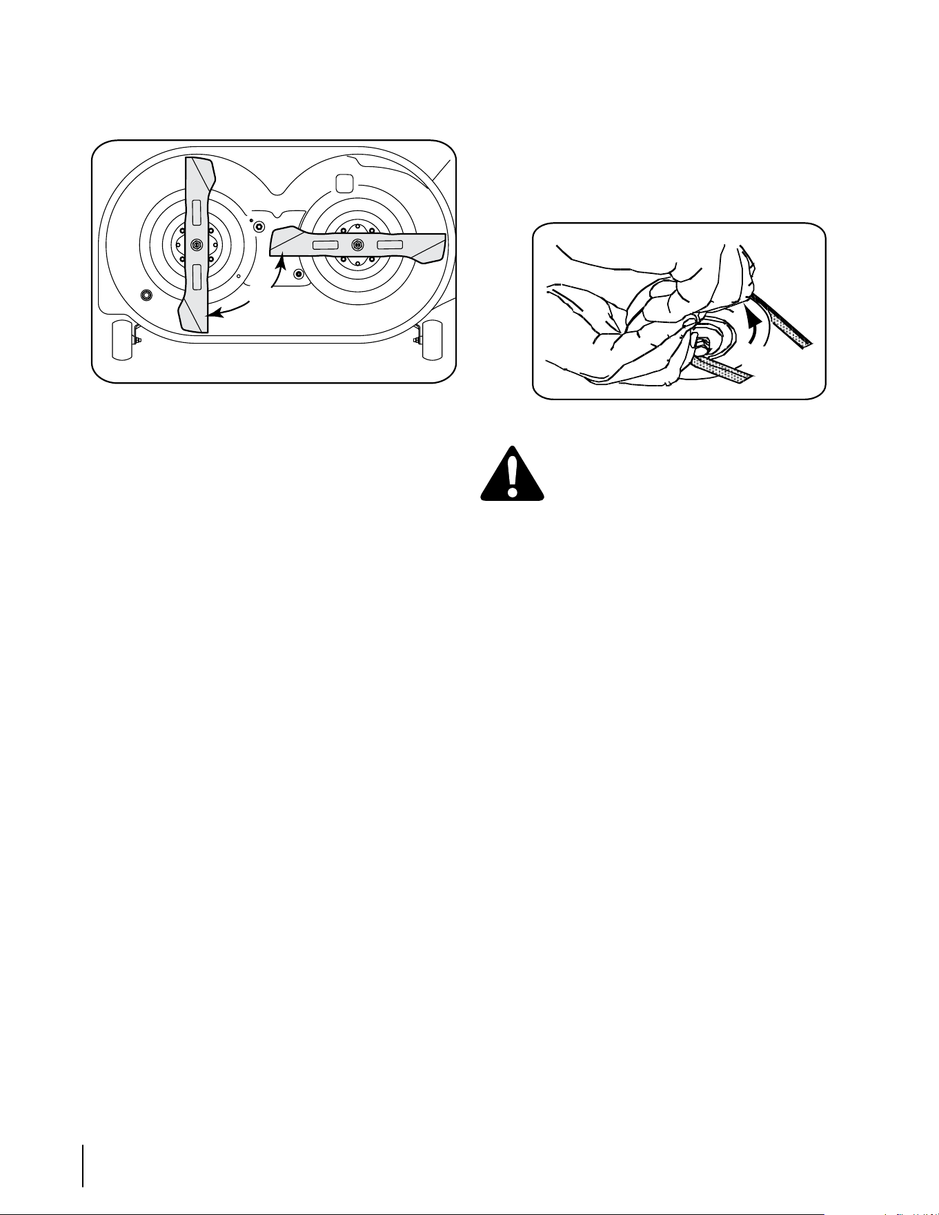
24 sectiOn 7— service
If the timing belt was installed correctly and the timing
arrows were positioned as shown in Figure 7-5, the cut-
ting blades should be in the position shown in Figure
7-6.
Figure 7-6
Reinstall the PTO belt onto the RH spindle drive pulley
and re-install the deck as described in “Re-installing the
Cutting Deck” below.
Reinstalling the Cutting Deck
There are two methods for reinstalling the mower deck
on the tractor. One method involves rotating the PTO belt
idler bracket to relieve enough belt tension to allow the
belt to be placed in either the PTO pulley or the fixed idler
pulley. Because that method is difficult, we recommend
using the second method of rolling the belt onto the PTO
pulley.
Install the cutting deck as follows:
From the right side of the tractor, slide the deck under
the tractor and align the rear deck hanger brackets with
the deck lift arms.
Slide the deck forward and place the deck front hanger
rod into the slots of the deck front hanger bracket. Then
slide the deck rearward so that the front hanger rod is
at the front of the slots.
Using the deck lift lever, lower the deck lift arms. From
either side of the tractor, pull the support pin in the
deck rear hanger bracket outward, align the deck lift
arm hole with the deck support pin and release the pin
so that it goes through the deck lift arm. Repeat on the
other side of the tractor to secure the deck.
After first making sure the deck belt is properly
engaged in all of the deck pulleys, route the deck belt
forward through the center of the front deck hanger
rod and toward the PTO pulley on the bottom of the
engine.
Using the deck lift handle, raise the deck to the posi-
tion that gives you the most horizontal run of the belt
between the deck pulleys and the PTO pulley on the
bottom of the engine.
Sitting in front of the tractor, facing rearward, make
certain the belt is not twisted; then reach beneath the
tractor to grasp the belt and pull it toward the PTO
pulley.
•
•
•
•
•
•
•
•
9
0
º
NOTE: References to left and right are from the front of the
tractor in the following instructions.
Pull the right side of the belt forward and place the nar-
row V side of the belt into the PTO pulley.
While holding the belt and pulley together, rotate the
pulley to the left. Continue holding and rotating the
pulley and belt until the belt is fully rolled into the PTO
pulley. See Figure 7-7.
Figure 7-7
WARNING: Use caution to prevent pinching
your fingers when rolling the belt onto the PTO
pulley.
Checking the Cutting Blade Timing
During normal operation the timing of the cutting blades
can be altered by abnormal loads on one, or both, cutting
blades. Regularly check the timing arrows on the spindle
assemblies to make certain they are 90° from each other.
If the timing arrows are not 90° from each other, proceed
as follows:
Remove the deck from the tractor. Remove the idler
bracket backstop. Refer to Figure 7-4.
Pivot the idler bracket/idler pulley to relieve the tension
on the timing belt, and reposition the drive pulley
and/or timing pulley to achieve the 90° orientation of
the timing arrows.
Re-install the idler bracket backstop and position so
that there is a 1/8" gap between the backstop and idler
bracket. Tighten the hex screw and flange lock nut to
secure in the adjusted position.
•
•
•
•
•
PTO Belt
Rotate
Pulley

Problem Cause Remedy
Engine fails to start PTO/Blade Engage knob engaged.
Parking brake not engaged.
Spark plug wire(s) disconnected.
Throttle control lever not in correct starting
position.
Choke not activated
Fuel tank empty, or stale fuel.
Blocked fuel line.
Faulty spark plug(s).
Engine flooded.
1.
2.
3.
4.
5.
6.
7.
8.
9.
Place knob in disengaged (OFF) position.
Engage parking brake.
Connect wire(s) to spark plug(s).
Place throttle lever to FAST position.
Pull the CHOKE control outward.
Fill tank with clean, fresh (less than 30 days
old) gas.
Clean fuel line and replace fuel filter.
Clean, adjust gap or replace plug(s).
Crank engine with throttle in FAST position.
1.
2.
3.
4.
5.
6.
7.
8.
9.
Engine runs erratic Unit running with CHOKE activated.
Spark plug wire(s) loose.
Blocked fuel line or stale fuel.
Vent in gas cap plugged.
Water or dirt in fuel system.
Dirty air cleaner.
1.
2.
3.
4.
5.
6.
Push CHOKE control in.
Connect spark plug wire(s).
Clean fuel line; fill tank with clean, fresh
gasoline and replace fuel filter.
Clear vent or replace cap if damaged.
Drain fuel tank. Refill with clean, fresh
gasoline.
Replace air cleaner paper element or clean
foam precleaner.
1.
2.
3.
4.
5.
6.
Engine overheats Engine oil level low.
Air flow restricted.
1.
2.
Fill crankcase with proper amount and
weight of oil.
Clean grass clippings and debris from around
the engine’s cooling fins and blower housing.
1.
2.
Engine hesitates at high
RPM
Spark plug(s) gap too close. 1. Remove spark plug(s) and reset the gap. 1.
Engine Idles rough Spark plug(s) fouled, faulty or gap too wide.
Dirty air cleaner.
1.
2.
Replace spark plug(s). Set plug gap.
Replace air cleaner element and/or clean
pre-cleaner.
1.
2.
Excessive vibration Cutting blade loose or unbalanced.
Damaged or bent cutting blade.
1.
2.
Tighten blade and spindle.
Replace blade.
1.
2.
Mower will not mulch grass Engine speed too low.
Wet grass.
Excessively high grass.
Dull blade.
1.
2.
3.
4.
Place throttle in FAST (rabbit) position.
Do not mulch when grass is wet.
Mow once at a high cutting height, then
mow again at desired height or make a
narrower cutting swath.
Sharpen or replace blade.
1.
2.
3.
4.
Uneven cut Deck not leveled properly.
Dull blade.
Uneven tire pressure.
1.
2.
3.
Perform side-to-side deck adjustment.
Sharpen or replace blade.
Check tire pressure in all four tires.
1.
2.
3.
Troubleshooting
8
25
Replacement Parts
9
26
Contact your Cub Cadet dealer to order replacement parts. If you do not have a dealer, call the Customer Dealer Referral Line at 1-877-
282-8684 or visit www.cubcadet.com to find the nearest Cub Cadet dealer in your area. Phone (800) 965-4CUB to order replacement
parts or a complete Parts Manual (have your full model number and serial number ready). Parts Manual downloads are also available
free of charge at www.cubcadet.com.
Changing the Timing Belt Model i1042
Lower Drive Belt - Contact Dealer 954-04134
Engine to Deck/ PTO Belt 954-04185
Deck Timing Belt 954-04167
Blades 942-04217 (Qty. 2)
Deck Spindle - Right Hand 618-04512
Deck Spindle - Left Hand 618-04516
Deck Front Ball Wheels 734-04155 (Qty. 2)
Battery 925-1707D
Starter Solenoid 725-04439
Ignition Keys 725-2054A
Engine Oil Filter KH-52-050-02
Engine Oil (Capacity 57.6 ounces) 737-3030A (1qt.)
Engine Air Filter Element KH-32-083-03-S
Engine Air Filter Foam Precleaner Element KH-32-083-05-S
Fuel Filter KH-25-050-22-S
Spark Plug 759-3336
Deck Discharge Chute Assembly 631-04254
MODEL DESCRIPTION
19A70001000 Twin Rear Bagger Grass Collector for 46" Deck
19A70002000 Mulching Kit
190-833-000 46” Dozer Blade
19A-102-100 18 Cubic Foot Steel Cart
19A-106-100 10 Cubic Foot Poly Cart
19A-105-100 48" Broadcast Spreader
19A-103-100 42" Sweeper
19A-104-100 25 Gallon Sprayer
19A-107-100 48" Dethatcher
19A-113-100 48" Poly Roller
19A-108-100 48" Plug Aerator
19A-109-100 48" Spike Aerator
Attachments & Accessories
10

CALIFORNIA EMISSION CONTROL WARRANTY STATEMENT
YOUR WARRANTY RIGHTS AND OBLIGATIONS
The California Air Resources Board and MTD Consumer Group Inc are pleased to explain the evaporative emission control system warranty on your 2008 lawn
mower. In California, new lawn mower must be designed, built and equipped to meet the State’s stringent anti-smog standards. MTD Consumer Group Inc must
warrant the EECS on your lawn mower for the period of time listed below provided there has been no abuse, neglect or improper maintenance of your lawn mower.
Your EECS may include parts such as the carburetor, fuel-injection system, the ignition system, catalytic converter, fuel tanks, fuel lines, fuel caps, valves,
canisters, filters, vapor hoses, clamps, connectors, and other associated emission-related components.
Where a warrantable condition exists, MTD Consumer Group Inc will repair your lawn mower at no cost to you including diagnosis, parts and labor.
MANUFACTURER’S WARRANTY COVERAGE:
This evaporative emission control system is warranted for two years. If any evaporative emission-related part on your equipment is defective, the part will be
repaired or replaced by MTD Consumer Group Inc.
OWNER’S WARRANTY RESPONSIBILITIES:
As the lawn mower owner, you are responsible for performance of the required maintenance listed in your owner’s manual. MTD Consumer Group Inc recom-
mends that you retain all receipts covering maintenance on your lawn mower, but MTD Consumer Group Inc cannot deny warranty solely for the lack of receipts.
As the lawn mower owner, you should however be aware that MTD Consumer Group Inc may deny you warranty coverage if your lawn mower or a part has failed
due to abuse, neglect, or improper maintenance or unapproved modifications.
You are responsible for presenting your lawn mower to MTD Consumer Group Inc’s distribution center or service center as soon as the problem exists. The
warranty repairs should be completed in a reasonable amount of time, not to exceed 30 days. If you have a question regarding your warranty coverage, you should
contact the MTD Consumer Group Inc Service Department at 1-800-800-7310.
GENERAL EMISSIONS WARRANTY COVERAGE:
MTD Consumer Group Inc warrants to the ultimate purchaser and each subsequent purchaser that the lawn mower is: Designed, built and equipped so as to
conform with all applicable regulations; and free from defects in materials and workmanship that cause the failure of a warranted part to be identical in all material
respects to that part as described in MTD Consumer Group Inc’s application for certification.
The warranty period begins on the date the lawn mower is delivered to an ultimate purchaser or first placed into service. The warranty period is two years.
Subject to certain conditions and exclusions as stated below, the warranty on emission-related parts is as follows:
1. Any warranted part that is not scheduled for replacement as required maintenance in the written instructions supplied, is warranted for the warranty period
stated above. If the part fails during the period of warranty coverage, the part will be repaired or replaced by MTD Consumer Group Inc according to subsection
(4) below. Any such part repaired or replaced under warranty will be warranted for the remainder of the period.
2. Any warranted part that is scheduled only for regular inspection in the written instructions supplied is warranted for the warranty period stated above. Any such
part repaired or replaced under warranty will be warranted for the remaining warranty period.
3. Any warranted part that is scheduled for replacement as required maintenance in the written instructions supplied is warranted for the period of time before the
first scheduled replacement date for that part. If the part fails before the first scheduled replacement, the part will be repaired or replaced by MTD Consumer
Group Inc according to subsection (4) below. Any such part repaired or replaced under warranty will be warranted for the remainder of the period prior to the
first scheduled replacement point for the part.
4. Repair or replacement of any warranted part under the warranty provisions herein must be performed at a warranty station at no charge to the owner.
5. Notwithstanding the provisions herein, warranty services or repairs will be provided at all of our distribution centers that are franchised to service the subject
engines or equipment.
6. The lawn mower owner will not be charged for diagnostic labor that is directly associated with diagnosis of a defective, emission-related warranted part,
provided that such diagnostic work is performed at a warranty station.
7. MTD Consumer Group Inc is liable for damages to other engine or equipment components proximately caused by a failure under warranty of any warranted
part.
8. Throughout the lawn mower warranty period stated above, MTD Consumer Group Inc will maintain a supply of warranted parts sufficient to meet the expected
demand for such parts.
9. Any replacement part may be used in the performance of any warranty maintenance or repairs and must be provided without charge to the owner. Such use will
not reduce the warranty obligations of MTD Consumer Group Inc.
10. Add-on or modified parts that are not exempted by the Air Resources Board may not be used. The use of any non-exempted add-on or modified parts by the
ultimate purchaser will be grounds for disallowing a warranty claims. MTD Consumer Group Inc will not be liable to warrant failures of warranted parts caused
by the use of a non-exempted add-on or modified part.
WARRANTED PARTS:
The repair or replacement of any warranted part otherwise eligible for warranty coverage may be excluded from such warranty coverage if MTD Consumer Group
Inc demonstrates that the lawn mower has been abused, neglected, or improperly maintained, and that such abuse, neglect, or improper maintenance was the
direct cause of the need for repair or replacement of the part. That notwithstanding, any adjustment of a component that has a factory installed, and properly
operating, adjustment limiting device is still eligible for warranty coverage. The following emission warranty parts list are covered: Fuel line, Fuel line Clamps

IMPORTANT: To obtain warranty coverage owner must present an
original proof of purchase and applicable maintenance records to the
servicing dealer. Please see the operator’s manual for information on
required maintenance and service intervals.
The limited warranty set forth below is given by Cub Cadet LLC with
respect to new merchandise purchased or leased and used in the United
States and/or its territories and possessions, and by MTD Products
Limited with respect to new merchandise purchased or leased and
used in Canada and/or its territories and possessions (either entity
respectively, “Cub Cadet”).
Cub Cadet warrants this product (excluding its Normal Wear Parts,
Batteries, Frame and Front Axle and Attachments as described below)
against defects in material and workmanship for a period of three (3)
years or one hundred twenty (120) operation hours, whichever comes
first, commencing on the date of original retail purchase or lease and
will, at its option, repair or replace, free of charge, any part found to be
defective in materials or workmanship.
Normal Wear Parts are warranted to be free from defects in material and
workmanship for a period of thirty (30) days from the date of original
purchase or lease. Normal wear parts include, but are not limited to
items such as: belts, blades, blade adapters, grass bags, rider deck
wheels, seats, and tires.
Batteries have a one-year prorated limited warranty against defects in
material and workmanship, with 100% replacement during the first three
months. After three months, the battery replacement credit is based on
the months remaining in the twelve (12) month period dating back to the
original date of original sale or lease. Any replacement battery will be
warranted only for the remainder of the original warranty period.
Frame and Front Axle — Cub Cadet warrants the frame, and front cast iron
pivot axle against defects in material and workmanship for a period of
five (5) years or 500 hours, whichever occurs first, commencing on the
date of original purchase or lease.
Attachments — Cub Cadet warrants attachments for this product against
defects in material and workmanship for a period of two (2) years,
commencing on the date of the attachment’s original purchase or
lease. Attachments include, but are not limited to items such as: grass
collectors and mulch kits.
This limited warranty shall only apply if this product has been operated
and maintained in accordance with the Operator’s Manual furnished
with the product, and has not been subject to misuse, abuse, neglect,
accident, improper maintenance, alteration, vandalism, theft, fire, water,
or damage because of other peril or natural disaster. Damage resulting
from the installation or use of any part, accessory or attachment not
approved by Cub Cadet for use with the product(s) covered by this
manual will void your warranty as to any resulting damage. In addition,
Cub Cadet may deny warranty coverage if the hour meter, or any part
thereof, is altered, modified, disconnected or otherwise tampered with.
HOW TO OBTAIN SERVICE: Warranty service is available, WITH PROOF
OF PURCHASE AND APPLICABLE MAINTENANCE RECORDS, through
your local authorized service dealer. To locate the dealer in your area:
In the U.S.A.:
Check your Yellow Pages, or contact Cub Cadet LLC at P.O. Box 361131,
Cleveland, Ohio 44136-0019, call 1-877-282- 8684
or log on to our website at www.cubcadet.com.
In Canada:
Contact MTD Products Limited, Kitchener, ON N2G 4J1, call 1-800-668-
1238 or log on to our website at www.mtdcanada.com.
Without limiting the foregoing, this limited warranty does not provide
coverage in the following cases:
a. Routine maintenance items such as lubricants, filters, blade
sharpening, tune-ups, brake adjustments, clutch adjustments, deck
adjustments, and normal deterioration of the exterior finish due to
use or exposure.
b. Service completed by someone other than an authorized service
dealer.
c. Cub Cadet does not extend any warranty for products sold or
exported outside of the United States and/or Canada, and their
respective possessions and territories, except those sold through
Cub Cadet’s authorized channels of export distribution.
d. Replacement parts and\or accessories that are not genuine Cub
Cadet parts.
e. Transportation charges and service calls.
There are no implied warranties, including without limitation any
implied warranty of merchantability or fitness for a particular
purpose. No warranties shall apply after the applicable period of
express written warranty above. No other express warranties beyond
those mentioned above, given by any person or entity, including a
dealer or retailer, with respect to any product, shall bind Cub Cadet.
The exclusive remedy is repair or replacement of the product as
set forth above. The terms of this warranty provide the sole and
exclusive remedy arising from the sale and/or lease of the products
covered hereby. Cub Cadet shall not be liable for any incidental or
consequential loss or damage including, without limitation, expenses
incurred for substitute or replacement lawn care services or for
rental expenses to temporarily replace a warranted product.
Some jurisdictions do not allow the exclusion or limitation of incidental
or consequential damages, or limitations on how long an implied
warranty lasts, so the above exclusions or limitations may not apply to
you.
In no event shall recovery of any kind be greater than the amount of the
purchase price of the product sold. Alteration of safety features of the
product shall void this warranty. You assume the risk and liability for
loss, damage, or injury to you and your property and/or to others and
their property arising out of the misuse or inability to use the product.
This limited warranty shall not extend to anyone other than the original
purchaser or to the person for whom it was purchased as a gift.
HOW LOCAL LAWS RELATE TO THIS WARRANTY: This limited warranty
gives you specific legal rights, and you may also have other rights that
vary in different jurisdictions.
CUB CADET LLC
MANUFACTURER’S LIMITED WARRANTY FOR
SERIES 1000 & SERIES 1500 TRACTORS
Cub Cadet LLC, P.O. BOX 361131 CLEVELAND, OHIO 44136-0019, Phone: 1-877-282-8684
MTD Products Limited, Kitchener, ON N2G 4J1, Phone: 1-800-668-1238
GDOC-100014 REV. B
CUB CADET LLC, P.O. BOX 361131 CLEVELAND, OHIO 44136-0019
Impreso en Estados Unidos de América
Manual del OperadOr
Medidas importantes de seguridad • Configuración • Funcionamiento • Mantenimiento • Servicio • Solución de problemas • Garantía
ADVERTENCIA
LEA Y RESPETE TODAS LAS NORMAS DE SEGURIDAD E INSTRUCCIONES INCLUIDAS
EN ESTE MANUAL ANTES DE PONER EN FUNCIONAMIENTO ESTA MÁQUINA.
SI NO RESPETA ESTAS INSTRUCCIONES PUEDE PROVOCAR LESIONES PERSONALES.
Tractor corta césped con radio de giro cero
Modelo Time Saver
i1042
FORMulARIO No. 769-03654
(Noviembre, 2007)

Asistencia al Cliente
En caso de tener problemas para montar este producto o de tener dudas con respecto a los controles, funcionamiento
o mantenimiento de esta máquina, puede solicitar la ayuda de expertos. Elija entre las opciones que se presentan a
continuación:
Visite nuestro sitio web en www.cubcadet.com
Localice a su distribuidor Cub Cadet más cercano llamando al (877) 282-8684
Escríbanos a Cub Cadet LLC • P.O. Box 361131 • Cleveland, OH • 44136-0019
◊
◊
◊
Gracias por comprar un tractor corta césped fabricado por
Cub Cadet LLC. El mismo ha sido diseñado cuidadosamente
para brindar excelente rendimiento si se lo opera y mantiene
correctamente.
Por favor lea todo este manual antes de operar el equipo.
Le indica cómo configurar, operar y mantener la máquina
con seguridad y fácilmente. Por favor asegúrese de seguir
cuidadosamente y en todo momento las prácticas de seguridad
recomendadas y de hacérselas seguir a cualquier otra persona
que opere la máquina. En caso de no hacerlo podrían producirse
lesiones personales o daños materiales.
Toda la información contenida en este manual hace referencia
a la más reciente información de producto disponible en el
momento de la impresión. Revise el manual frecuentemente
para familiarizarse con la máquina, sus características y
funcionamiento. Por favor tenga en cuenta que este Manual
del Operador puede cubrir una gama de especificaciones de
producto de diferentes modelos. Las características y funciones
incluidas y/o ilustradas en este manual pueden no ser aplicables
a todos los modelos. Cub Cadet LLC se reserva el derecho de
modificar las especificaciones de los productos, los diseños y
el equipo sin previo aviso y sin generar responsabilidad por
obligaciones de ningún tipo.
Este producto cumple con las estrictas normas de seguridad
del Outdoor Power Equipment Institute y de un laboratorio de
pruebas independiente. Si tiene algún problema o duda respecto
a la máquina, llame a su distribuidor de servicio local Cub Cadet
autorizado o póngase en contacto directamente con nosotros.
Los números de teléfono, dirección del sitio web y dirección
postal de la Asistencia al Cliente de Cud Cadet se encuentran en
esta página. Queremos garantizar su entera satisfacción en todo
momento.
En este manual, las referencias al lado derecho o izquierdo de la
máquina se observan desde la posición del operador.
Gracias
Registro de información de producto
Antes de configurar y operar su equipo nuevo, por favor localice
la placa de modelo en el equipo y registre la información en el
área situada a la derecha. Puede localizar la placa de modelo
mirando debajo del asiento. Si tiene que solicitar soporte técnico
a través de nuestro sitio web o de un distribuidor Cub Cadet
local, necesitará esta información.
núMerO de MOdelO
núMerO de serie
Medidas importantes de seguridad ...................... 3
Montaje y Configuración ........................................ 8
Controles y Características .................................... 9
Funcionamiento .....................................................12
Mantenimiento y Ajustes .......................................15
Servicio ................................................................... 20
Solución de problemas ......................................... 25
Piezas de reemplazo ............................................. 26
Aditamentos y accesorios .................................... 26
Garantía ...................................... Cubierta posterior
Índice
Al propietario
1
2
Medidas importantes de seguridad
2
3
NIñOS
Pueden ocurrir accidentes trágicos si el operador no
está atento a la presencia de niños. Por lo general, los
niños se sienten atraídos por este tipo de máquinas y su
funcionamiento. No entienden los riesgos ni los peligros.
Nunca asuma que los niños permanecerán en el mismo
lugar donde los vio por última vez.
Mantenga a los niños fuera del área de trabajo y bajo
estricta vigilancia de un adulto responsable además
del propio operador.
Esté alerta y apague la máquina si un niño ingresa
al área.
Antes de retroceder y mientras lo hace, mire hacia
atrás y abajo para ver si hay niños.
Nunca transporte niños, aún con la cuchilla apagada.
Podrían caerse y resultar severamente heridos o
interferir con la operación segura de la máquina.
Tenga extrema precaución cuando se aproxime a
esquinas ciegas, portales, arbustos, árboles u otros
objetos que puedan impedirle ver a un niño que
pueda chocar con la máquina.
Para evitar accidentes al operar en marcha atrás,
siempre desenganche las cuchillas antes de
colocar marcha atrás. Si está instalado, el “Modo
Precaución Marcha Atrás” no debe utilizarse
cuando hay niños u otras personas presentes.
1.
a.
b.
c.
d.
e.
f.
Mantenga a los niños alejados de los motores en
marcha o calientes. Pueden sufrir quemaduras por el
contacto con un silenciador caliente.
Retire la llave cuando deje la máquina sin vigilancia,
para impedir que una persona sin autorización la
maneje.
No permita nunca que los niños menores de 14 años utilicen
esta máquina. Los niños de 14 años en adelante deben
leer y entender las instrucciones de operación y normas de
seguridad contenidas en este manual, y en la máquina y
deben ser entrenados y supervisados por un adulto.
Funcionamiento
Manejo seguro de la gasolina:
Para evitar lesiones personales o daños materiales sea
sumamente cuidadoso al manipular la gasolina. La
gasolina es sumamente inflamable y sus vapores
pueden causar explosiones. Se puede lesionar
gravemente si derrama gasolina sobre usted o sobre la
ropa, ya que ésta se puede incendiar. Lávese la piel y
cámbiese de ropa de inmediato.
Utilice sólo los recipientes para gasolina autorizados.
Nunca llene los recipientes en el interior de
un vehículo o camión o caja de remolque con
recubrimiento plástico. Antes de llenarlos, coloque
siempre los recipientes en el suelo y lejos del vehículo.
g.
h.
2.
1.
a.
b.
ADVERTENCIA: La presencia de este símbolo indica que se trata de instrucciones
importantes de seguridad que se deben respetar para evitar poner en peligro su seguridad
personal y/o material y la de otras personas. Lea y siga todas las instrucciones de este
manual antes de poner en funcionamiento esta máquina. Si no respeta estas instrucciones
puede provocar lesiones personales. Cuando vea este símbolo. ¡TENGA EN CUENTA LAS
ADVERTENCIAS!
PELIGRO: Esta máquina está diseñada para ser utilizada respetando las prácticas de
seguridad contenidas en este manual. Al igual que con cualquier tipo de equipo motorizado, un
descuido o error por parte del operador puede producir lesiones graves. Esta máquina es capaz
de amputar manos y pies y de arrojar objetos con gran fuerza. De no respetar las instrucciones
de seguridad siguientes se pueden producir lesiones graves o la muerte.
PROPOSICIóN 65 DE CALIFORNIA
ADVERTENCIA: El escape del motor de este producto, algunos de sus componentes y
algunos componentes del vehículo contienen o liberan sustancias químicas que el estado de
California considera que pueden producir cáncer, defectos de nacimiento u otros problemas
reproductivos.
ADVERTENCIA: Los bornes de la batería y los accesorios afines contienen plomo y
compuestos de plomo, sustancias químicas que según lo establecido por el Estado de
California causan cáncer y daños en el sistema reproductivo. Lávese las manos después de
estar en contacto con estos componentes.

4 sección 2 — Medidas iMpOrtantes de seguridad
Cuando sea factible, retire el equipo a gasolina del
camión o remolque y llénelo en el suelo. Si esto no
es posible, llene el equipo en un remolque con un
contenedor portátil, en vez de con una boquilla
dispensadora de gasolina.
Mantenga la boquilla de llenado en contacto con el
borde del depósito de combustible o con la abertura
del recipiente en todo momento, hasta terminar
la carga. No utilice un dispositivo de boquilla de
apertura/cierre.
Apague todos los cigarrillos, cigarros, pipas y otras
fuentes de combustión.
Nunca cargue combustible en la máquina en un
espacio cerrado.
Nunca saque la tapa del combustible ni agregue
combustible mientras el motor está caliente o en
marcha. Deje que el motor se enfríe por lo menos
dos minutos antes de volver a cargar combustible.
Nunca llene en exceso el depósito de combustible.
Llene el depósito no más de ½ pulgada por debajo
de la base del cuello de llenado, para dejar espacio
para la expansión del combustible.
Vuelva a colocar la tapa de la gasolina y ajústela bien.
Limpie el combustible que se haya derramado sobre
el motor y el equipo. Traslade la máquina a otra
zona. Espere 5 minutos antes de encender el motor.
Para reducir el riesgo de incendio, mantenga la
máquina limpia de pasto, hojas y de acumulación
de otros residuos. Limpie los derrames de aceite o
combustible y saque todos los residuos embebidos
de combustible.
Nunca guarde la máquina o el recipiente de
combustible en un espacio cerrado donde haya
fuego, chispas o luz piloto, como por ejemplo de
calentadores de agua, calefactores de ambientes,
hornos, secadores de ropa u otros aparatos a gas.
Deje que la máquina se enfríe cinco minutos por lo
menos antes de guardarla.
Funcionamiento general:
Lea, entienda y cumpla todas las instrucciones incluidas en
la máquina y en los manuales antes de montarla y utilizarla.
Guarde este manual en un lugar seguro para consultas
futuras y periódicas, así como para solicitar repuestos.
Familiarícese con todos los controles y con el uso adecuado
de los mismos. Sepa cómo detener la máquina y desactivar
los controles rápidamente.
No permita nunca que los niños menores de 14 años
utilicen esta máquina. Los niños de 14 años y mayores
deben leer y comprender las instrucciones de operación
y las reglas de seguridad contenidas en este manual, y
también deben ser capacitados y estar supervisados por
uno de los padres.
Nunca permita que los adultos operen esta máquina sin
recibir antes la instrucción apropiada.
Para ayudar a evitar el contacto con las cuchillas o una
lesión por algún objeto que sea arrojado, mantenga a los
observadores, a los ayudantes, niños y mascotas alejados
al menos 25 metros de la máquina mientras está en
funcionamiento. Detenga la máquina si alguien se acerca.
Inspeccione minuciosamente el área donde utilizará el
equipo. Retire todas las piedras, palos, cables, huesos,
juguetes y otros objetos extraños que podrían ser recogidos
c.
d.
e.
f.
g.
h.
i.
j.
k.
l.
m.
1.
2.
3.
4.
5.
6.
y arrojados por la acción de las cuchillas. Los objetos
arrojados por la máquina pueden producir lesiones graves.
Planifique el patrón de corte del césped que ha de seguir
para evitar la descarga de material hacia los caminos, las
veredas, los observadores, etc. Evite además descargar
material contra las paredes u obstrucciones que podrían
hacer que el material descargado rebote contra el operador.
Para protegerse los ojos utilice siempre anteojos o
antiparras de seguridad mientras opera la máquina o
mientras la ajusta o repara. Los objetos arrojados que
rebotan pueden producir lesiones oculares graves.
Utilice zapatos de trabajo resistentes, de suela fuerte, así
como pantalones y camisas ajustados. Las prendas sueltas o
las alhajas pueden quedar atrapadas en las piezas movibles.
Nunca opere la máquina descalzo o con sandalias.
Esté atento a la cortadora y a la dirección de la descarga
de los aditamentos y no apunte a nadie. Nunca opere la
cortadora de césped sin que estén en su lugar apropiado la
cubierta de descarga o el colector de recortes de césped.
No ponga las manos o los pies cerca de las piezas rotatorias
o debajo de la plataforma de corte. El contacto con las
cuchillas puede producir la amputación de manos y pies.
Una cubierta de descarga faltante o dañada puede provocar
el contacto con la cuchilla o lesiones por objetos arrojados.
Detenga la(s) cuchilla(s) cuando atraviese senderos, sendas
o caminos de grava y cuando no esté cortando el césped.
Vigile el tránsito vehicular cuando esté operando cerca de
o en cruces de caminos. Esta máquina no debe utilizarse en
la vía pública.
No opere esta máquina bajo los efectos del alcohol o de drogas.
Corte el césped solamente con luz de día o con una buena
luz artificial.
Nunca transporte pasajeros.
Desenganche la(s) cuchilla(s) antes de colocar la marcha
atrás. Retroceda lentamente. Siempre mire hacia abajo y
hacia atrás antes de retroceder y mientras lo hace, para
evitar accidentes por manejar marcha atrás.
Reduzca la velocidad antes de dar la vuelta. Opere la
máquina suavemente. Evite la operación errática y la
velocidad excesiva.
Desenganche la(s) cuchilla(s), coloque el freno de
estacionamiento, detenga el motor y espere hasta que la(s)
cuchilla(s) se detenga(n) por completo antes de retirar el
colector de césped, vaciar los recortes, destapar el canal,
retirar restos de césped o desechos, o hacer cualquier ajuste.
Nunca deje la máquina en funcionamiento sin vigilancia.
Apague siempre las cuchillas, coloque la transmisión en
neutral, coloque el freno de mano, detenga el motor y
retire la llave antes de bajarse del vehículo.
Tenga sumo cuidado al cargar o descargar la máquina en
un remolque o camión. Esta unidad no debe conducirse
en ascenso o descenso de rampas, porque podría ladearse
y provocar lesiones personales graves. En las rampas la
máquina se debe empujar manualmente para cargarla o
descargarla correctamente.
El silenciador y el motor se calientan y pueden causar
quemaduras. No los toque.
Revise el espacio libre por encima de la cabeza antes de
conducir bajo ramas bajas de árboles, cables, cerramientos
de puertas, etc. en los cuales el operador podría atorarse o
ser empujado fuera de la máquina, lo que podría resultar
en lesiones graves.
7.
8.
9.
10.
11.
12.
13.
14.
15.
16.
17.
18.
19.
20.
21.
22.
23.
24.

5sección 2 — Medidas iMpOrtantes de seguridad
Desenganche todos los embragues de los accesorios,
presione totalmente el pedal del freno y cambie a neutral
antes de intentar arrancar el motor.
La máquina está diseñada para cortar césped residencial
normal, con una altura no mayor a 10”. No intente cortar
césped demasiado crecido, seco (por ej., pastura) ni pilas
de hojas secas. El césped y las hojas secas pueden entrar
en contacto con el escape del motor y/o acumularse en la
plataforma de la cortadora de césped, convirtiéndose en
un peligro de incendio
Utilice solamente accesorios y aditamentos aprobados
para esta máquina por el fabricante de la misma. Lea,
comprenda y siga todas las instrucciones proporcionadas
con los accesorios o aditamentos aprobados.
Los datos estadísticos muestran que los operadores de 60
años y mayores se ven involucrados en un alto porcentaje
de lesiones relacionadas con tractores corta césped. Estos
operadores deben evaluar su capacidad para operar el
tractor corta césped en forma suficientemente segura para
protegerse a ellos mismos y a los demás contra lesiones
graves.
Si se presentan situaciones que no están previstas en este
manual, sea cuidadoso y use el sentido común. Si necesita
ayuda, póngase en contacto con su representante de
asistencia al cliente.
Funcionamiento en pendientes:
Las pendientes son un factor importante relacionado con
accidentes por derrape y vuelcos que pueden producir lesiones
graves e incluso la muerte. La operación en pendientes requiere
mayor precaución. Si no puede retroceder en la pendiente o si
no se siente seguro, no realice ninguna operación de corte.
Para su seguridad, use el indicador de pendientes que se incluye
como parte de este manual para medir la pendiente antes de
operar la máquina en una zona inclinada. Si la pendiente es
mayor de 15 grados según el medidor, no opere esta máquina en
ese sector, pues podría causar lesiones graves.
Haga lo siguiente:
Pode hacia arriba y abajo de las pendientes, no de forma
transversal. Tenga cuidado cuando cambie de dirección al
operar en pendiente.
Esté atento a los hoyos, surcos, baches, rocas u otros
objetos ocultos. El terreno desnivelado puede voltear la
máquina. El césped alto puede ocultar obstáculos.
Vaya a baja velocidad. Elija una velocidad lo
suficientemente baja, de modo que no tenga que
detenerse o hacer cambios mientras está sobre la
pendiente. Los neumáticos podrían perder tracción
sobre las pendientes aún cuando los frenos funcionaran
apropiadamente. Siempre mantenga la máquina en
cambio mientras desciende las pendientes, para poder
frenar con el motor.
Siga las recomendaciones del fabricante para los pesos o
contrapesos de las ruedas, para mejorar la estabilidad de la
máquina.
Tenga especial cuidado con los colectores de césped
u otros aditamentos. Los mismos pueden modificar la
estabilidad de la máquina.
Haga que todos los movimientos en las pendientes sean
lentos y graduales. No cambie repentinamente la velocidad
ni la dirección. Un frenado o cambio de velocidad
repentinos pueden causar que el frente de la máquina
se levante y dé una voltereta hacia atrás, lo que podría
producir lesiones graves.
25.
26.
27.
28.
29.
1.
2.
3.
4.
5.
6.
Evite arrancar o detenerse en una pendiente. Si los
neumáticos pierden la tracción, desenganche las cuchillas y
descienda lentamente la pendiente.
No haga lo siguiente:
No gire sobre las pendientes a menos que sea necesario.
Si es posible, gire lentamente y gradualmente durante el
descenso.
No corte el césped cerca de pozos, hundimientos o
terraplenes. La cortadora de césped puede volcarse
repentinamente si una de las ruedas está sobre el borde de
un acantilado, zanja o si un borde se desmorona.
No intente estabilizar la máquina poniendo el pie en el
suelo.
No utilice un colector de césped en pendientes empinadas.
No pode el césped húmedo. Una menor tracción podría
causar derrapes.
No cambie a transmisión neutral para descender. El exceso
de velocidad puede hacer que el operador pierda el control
de la máquina, ocasionando lesiones graves e incluso la
muerte.
No remolque cargas pesadas detrás de los aditamentos
(carrito de basura cargado, podadora de rodillos, etc) en
pendientes mayores de 5 grados. Cuando se desciende, el
peso adicional tiende a empujar el tractor y puede hacer
que se pierda el control. (por ejemplo, el tractor puede
acelerarse, se reduce la capacidad de frenar y maniobrar,
los accesorios pueden plegarse como un cortaplumas y
hacer que el tractor vuelque).
Remolque:
Remolque únicamente con una máquina que cuente con
un enganche diseñado para remolcar. No acople equipo
remolcado excepto en el punto de enganche.
Siga las recomendaciones del fabricante en lo que respecta
a los límites de peso de los equipos a remolcar y al
remolque en pendientes.
Nunca permita la presencia de niños u otras personas
dentro o sobre los equipos remolcados.
En las pendientes, el peso del equipo remolcado puede
causar pérdida de tracción y pérdida de control de la
máquina.
Desplácese lentamente y deje distancia adicional para
frenado.
No cambie a transmisión neutral para descender.
Servicio
Nunca encienda el motor en espacios cerrados o en una
zona con poca ventilación. El escape del motor contiene
monóxido de carbono, un gas inodoro y letal.
Antes de limpiar, reparar o inspeccionar la máquina,
compruebe que la(s) cuchilla(s) y todas las partes en
movimiento se hayan detenido. Desconecte el cable de la
bujía y póngalo haciendo masa contra el motor para evitar
que se encienda accidentalmente.
Revise periódicamente para asegurarse que las cuchillas
se detengan por completo en aproximadamente cinco (5)
segundos después de accionar el control de desenganche
de la(s) cuchilla(s). Si las cuchillas no se detienen dentro de
este lapso de tiempo, su unidad deberá ser reparada por su
distribuidor de servicio autorizado MTD.
Revise con frecuencia el funcionamiento del sistema de
frenos ya que está sujeto a desgaste por la operación
normal. Ajuste y efectúe mantenimiento según se requiera.
7.
1.
2.
3.
4.
5.
6.
7.
1.
2.
3.
4.
5.
6.
1.
2.
3.
4.

6 sección 2 — Medidas iMpOrtantes de seguridad
Revise los pernos de montaje de la(s) cuchilla(s) y del
motor a intervalos frecuentes para verificar que estén
bien apretados. Además, inspeccione visualmente la(s)
cuchilla(s) en busca de daños (por ejemplo, desgaste
excesivo, abolladuras, rajaduras, etc.). Reemplace la(s)
cuchilla(s) únicamente con las cuchillas de fabricantes de
equipos originales (O.E.M.) enumerados en este manual.
“El uso de piezas que no cumplen con las especificaciones
del equipo original podría tener como resultado un
rendimiento incorrecto y además poner en riesgo la
seguridad”.
Las cuchillas de las podadoras son muy afiladas. Envuelva
la cuchilla o utilice guantes y extreme las precauciones
cuando efectúe el mantenimiento.
Mantenga todos los pernos, tuercas y tornillos bien
ajustados para asegurarse de que la máquina se encuentra
en condiciones seguras de operación.
Nunca altere el sistema de enclavamiento de seguridad ni
otros mecanismos de seguridad. Controle periódicamente
que funcionen correctamente.
Después de golpear con algún objeto extraño, detenga el
motor, desconecte el cable de la bujía y conecte el motor a
masa. Inspeccione minuciosamente la máquina para ver si
está dañada. Repare el daño antes de arrancar y utilizar la
máquina.
Nunca trate de hacer ajustes o reparaciones a la máquina
mientras el motor está en marcha.
Los componentes del colector de césped y la cubierta de
descarga, están sujetos a desgaste y daños que podrían
dejar expuestas partes en movimiento o permitir que se
arrojen objetos. Para proteger su seguridad, verifique
frecuentemente todos los componentes y reemplácelos
inmediatamente sólo con piezas de los fabricantes del
equipo original, enumerados en este manual. “El uso de
piezas que no cumplen con las especificaciones del equipo
original podría tener como resultado un rendimiento
incorrecto y además poner en riesgo la seguridad”.
No cambie la configuración del regulador del motor ni lo
opere a sobrevelocidad. El regulador del motor controla la
velocidad máxima segura de funcionamiento del motor.
Mantenga o reemplace las etiquetas de seguridad e
instrucciones según sea necesario.
Respete las normas referentes a la disposición correcta y las
reglamentaciones sobre gasolina, aceite, etc. para proteger
el medio ambiente.
No modifique el motor
Para evitar lesiones graves o la muerte, no modifique el motor
bajo ninguna circunstancia. Si cambia la configuración del
regulador del motor, éste puede descontrolarse y operar a
velocidades inseguras. Nunca cambie la configuración de fábrica
del regulador del motor.
5.
6.
7.
8.
9.
10.
11.
12.
13.
14.
Aviso referido a emisiones
Los motores que están certificados y cumplen con las
regulaciones de emisiones federales EPA y de California para
SORE (Equipos pequeños todo terreno) están certificados para
operar con gasolina común sin plomo y pueden incluir los
siguientes sistemas de control de emisiones: Modificación de
motor (EM) y catalizador de tres vías (TWC) si están equipados de
esa manera.
Amortiguador de chispas
ADVERTENCIA: Esta máquina está equipada
con un motor de combustión interna y no debe ser
utilizada en un terreno agreste cubierto por bosque,
malezas o hierba ni cerca del mismo excepto que el
sistema de escape del motor esté equipado con un
amortiguador de chispas que cumpla con las leyes
locales o estatales correspondientes (en caso de
haber).
Si se utiliza un amortiguador de chispas el operador lo debe
mantener en condiciones de uso adecuadas. En el Estado
de California las medidas anteriormente mencionadas son
exigidas por ley (Artículo 4442 del Código de Recursos Públicos
de California). Es posible que existan leyes similares en otros
estados. Las leyes federales se aplican en territorios federales.
Puede conseguir el amortiguador de chispas para el silenciador
a través de su distribuidor de mantenimiento de motores
autorizado más cercano o poniéndose en contacto con el
departamento de servicios, Apartado Postal 361131 Cleveland,
Ohio 44136-0019.
Vida útil media
Según la Comisión de Seguridad de Productos para el
Consumidor de los Estados Unidos (CPSC) y la Agencia de
Protección Ambiental de los Estados Unidos (EPA), este
producto tiene una vida útil media de siete (7) años ó 270 horas
de funcionamiento. Al finalizar la vida útil media, adquiera una
máquina nueva o haga inspeccionar anualmente ésta por un
distribuidor de servicio autorizado para cerciorarse de que todos
los sistemas mecánicos y de seguridad funcionan correctamente
y no tienen excesivo desgaste. Si no lo hace, pueden producirse
accidentes, lesiones o muerte.
ADVERTENCIA: Su responsabilidad:Restrinja el uso de esta máquina motorizada a las personas que lean,
comprendan y respeten las advertencias e instrucciones que figuran en este manual y en la máquina.
GUARDE ESTAS INSTRUCCIONES
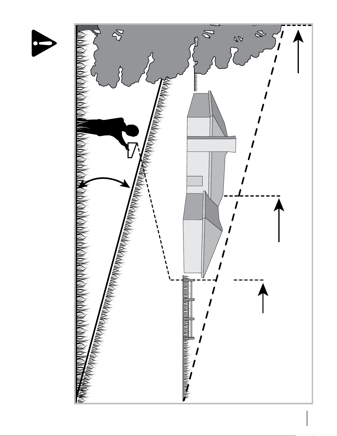
7sección 2 — Medidas de seguridad
Mire y mantenga este nivel con un árbol vertical...
o la esquina de un edicio...
o una cerca.
Doble por la línea de puntos (representa una pendiente de 15°)
15°
Use esta página como guía para determinar en qué pendientes no puede operar el tractor de manera segura.
ADVERTENCIA: No opere la cortadora de césped en dichas pendientes. No corte en pendientes con una inclinación de más
de 15 grados (elevación aproximada de 2 1/2 pies por cada 10 pies). El tractor corta césped podría voltearse y causar lesiones
graves. En las pendientes opere con los tractores corta-césped hacia arriba y abajo, nunca de forma transversal.
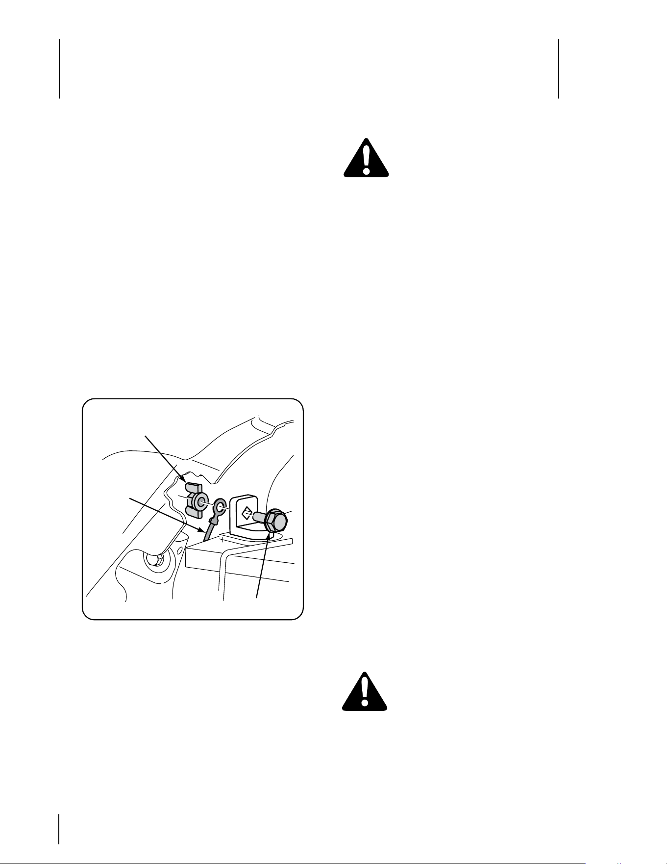
Montaje y Configuración
3
8
Carga de gasolina
ADVERTENCIA: Tenga mucho cuidado al
trabajar con gasolina. La gasolina es sumamente
inflamable y sus vapores pueden causar
explosiones. Nunca cargue combustible en
la máquina en un espacio cerrado o cuando
el motor está caliente o en marcha. Apague
cigarrillos, cigarros, pipas y otras fuentes de
combustión.
nOta:
Compre gasolina en pequeñas cantidades. No use
gasolina que haya quedado de la temporada anterior, para
minimizar la formación de depósitos de goma en el sistema
de combustible.
Este motor está habilitado para funcionar con gasolina
sin plomo. Para obtener el mejor resultado, llene el
depósito de combustible únicamente con gasolina
sin plomo limpia y fresca, en un surtidor que indique
un octanaje igual a 87 o más. En países que utilizan el
método de investigación, debería ser un mínimo de 90
octanos.
Se recomienda el uso de gasolina sin plomo porque deja
menos depósitos en la cámara de combustión y reduce
las emisiones de escape perjudiciales. No se recomienda
el uso de gasolina con plomo; no se la debe usar en
los lugares en los cuales las emisiones de escape se
encuentran reguladas.
El gasohol (hasta 10% de alcohol etílico, 90% de gasolina
sin plomo por volumen) es un combustible aprobado. No
se aprueba el uso de otras mezclas de gasolina/alcohol.
El éter metílico terciario-butílico (MTBE) y las mezclas
de gasolina sin plomo (hasta un máximo de 15% de
MTBE por volumen) son combustibles aprobados. No se
aprueba el uso de otras mezclas de gasolina/éter.
El tanque de gasolina está debajo del guardabarros trasero, y
el tapón de llenado de combustible se encuentra en el centro
del guardabarros trasero. El tapón del combustible está
amarrado al tractor para impedir que se pierda. No intente
retirar el tapón del tractor.
IMPORTANTE: Su tractor se envía con aceite en el motor. Sin
embargo, usted DEBE controlar el nivel de aceite antes de hacerlo
funcionar. Consulte el Manual del motor del propietario que se
suministra con el tractor para ver las instrucciones para el control
del nivel de aceite.
Presión de los neumáticos
ADVERTENCIA: La presión máxima de los
neumáticos en cualquier circunstancia es de 25
psi. Se debe mantener una presión uniforme
para todos los neumáticos en todo momento.
Tal vez los neumáticos de la unidad hayan sido inflados en
exceso para el envío del producto. Reduzca la presión de
los neumáticos antes de operar el tractor. La presión de
neumáticos recomendada para el funcionamiento del tractor
es de aproximadamente 10 p.s.i. para los neumáticos traseros
y de 14 p.s.i. para los neumáticos delanteros. Consulte en los
laterales de los neumáticos la presión máxima en p.s.i.
•
•
•
•
Apertura del capó del tractor
Para unir el cable negativo de la batería e inspeccionar el
nivel de aceite del motor, el capó debe estar abierto. Localice
la muesca de elevación del capó (Consulte la Figura 4 de la
página 10) en el frente/centro del panel de instrumentos.
Sujete el capó por la muesca y levante y pivote el capó hacia
adelante para abrirlo.
Instalación de los cables de la batería
El tractor se envía con una batería sellada activada. El cable
positivo de la batería viene conectado de fábrica. El cable
negativo se debe conectar. El borne positivo de la batería está
marcado como Pos (+). El borne negativo de la batería está
marcado como Neg (-).
IMPORTANTE: Asegúrese de que el interruptor de encendido
está en la posición “OFF” (apagado) antes de unir los cables de la
batería.
Levante el capó del tractor desde la muesca central
del frente del panel de instrumentos y pivótelo hacia
adelante para abrirlo.
Retire el perno con reborde hexagonal y la tuerca de
mariposa del cable (negro) negativo.
Figura 3-1
Extraiga el tapón protector, si hubiere, del borne negativo
de la batería. Una el cable negativo (pesado y de color
negro) al borne negativo de la batería (–) utilizando el
perno y la tuerca de mariposa. Vea la Figura 1.
El cable positivo (de color rojo) está sujeto al borne
positivo de la batería (+) por medio del perno del carro
y una tuerca hexagonal, según configuración de fábrica.
Asegúrese de que el borne positivo de la batería esté
cubierto con el capuchón de goma.
NOTA: Si la batería se pone en funcionamiento después
de la fecha indicada en su parte superior, cargue la batería
siguiendo las instrucciones de la página 20 de este manual
antes de operar el tractor.
•
•
•
•
Tuerca de mariposa
Cable
negativo de
la batería
Perno con reborde
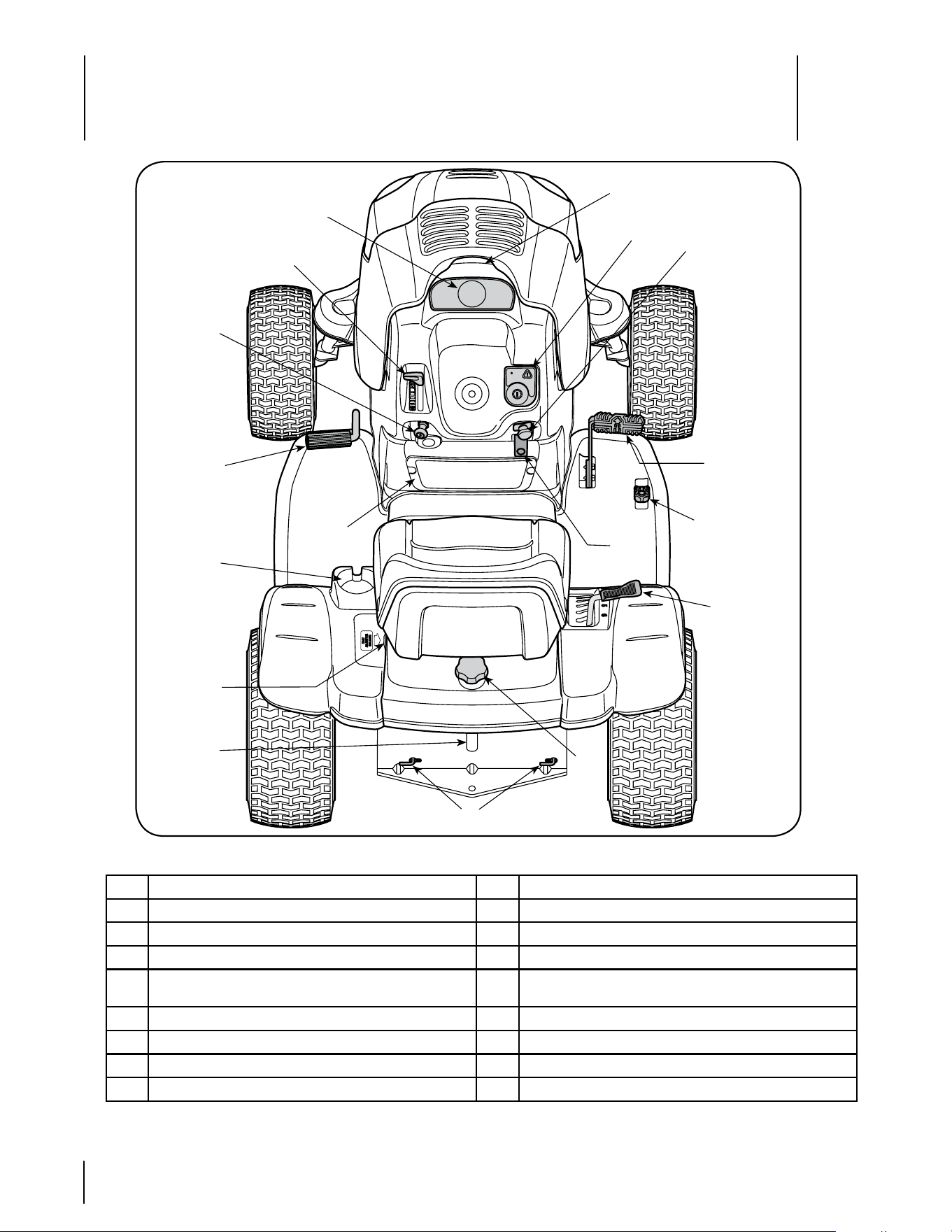
Controles y Características
4
9
Figura 4-1
C
A Monitor indicador de sistemas/ medidor horario J Palanca de elevación de la plataforma
B Palanca de control del regulador K Portacubeta
C Módulo del interruptor de llave L Palanca de ajuste del asiento
D Perilla de control del cebador M Tapón de llenado de combustible
E
Interruptor de la potencia de arranque
(enganche de cuchilla)
N Varillas de derivación de transmisión hidrostática
F Palanca de freno de mano O Visor del nivel de combustible
G Pedal de control de avance P Red de carga
H Pedal de control de marcha atrás Q Muesca de elevación del capó
I Pedal de freno
A
B
D
E
F
G
H
I
J
K
L
M
O
N
P
Q
NOTA: Cualquier referencia hecha en este manual al lado DERECHO o IZQUIERDO del tractor debe entenderse tal como
se observa desde la posición del operador.
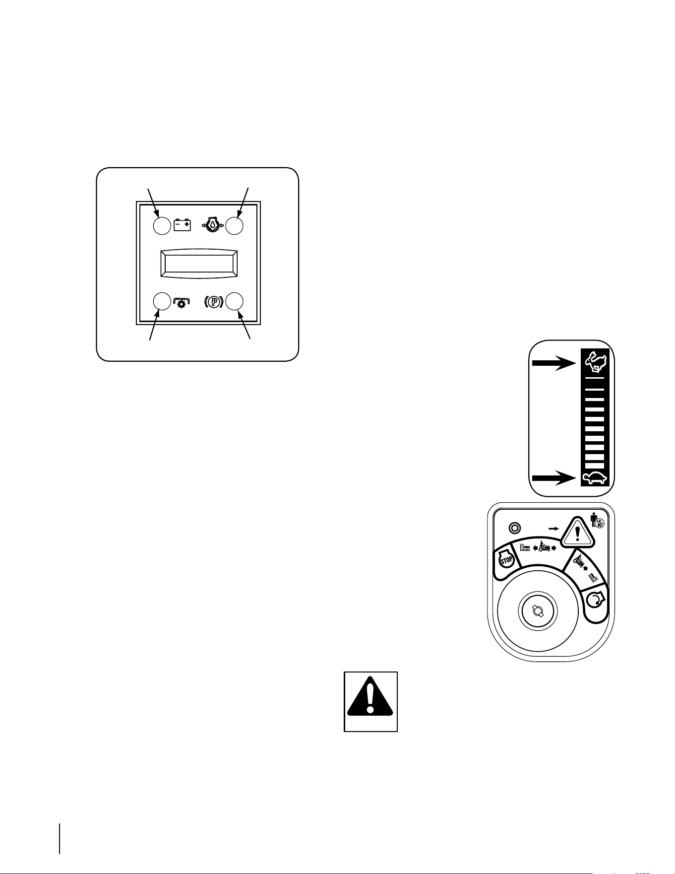
10 sección 4— cOntrOles y características
Luz indicadora de presión de aceite
Esta lámpara de advertencia indica que hay baja presión de aceite del
motor. Si este indicador se ilumina, detenga inmediatamente el tractor y
revise el nivel de aceite del motor. Si el nivel de aceite se encuentra dentro
del rango operativo pero la luz se mantiene encendida, póngase en
contacto con su distribuidor Cub Cadet. NOTA: El indicador de presión de
aceite puede iluminarse cuando el interruptor de llave se gira a la posición
de encendido pero debería apagarse cuando se arranca el motor.
Luz indicadora de potencia de arranque conectada
Este indicador se ilumina cuando el interruptor de llave se gira a la
posición “START” (ENCENDIDO) mientras el interruptor de la potencia
de arranque está en la posición “ENGAGED” (CONECTADO).
Inspeccione este indicador si el motor no gira con el interruptor llave en
la posición “START” (ENCENDIDO). Mueva el interruptor de potencia
de arranque a la posición “DISENGAGED” (DESCONECTADO).
Indicador de freno engranado
Este indicador se ilumina cuando el interruptor de llave se gira a
la posición “START” (ENCENDIDO) y el pedal de freno no está
totalmente presionado. Inspeccione este indicador si el motor no gira
con el interruptor llave en la posición “START” (ENCENDIDO). De ser
necesario, presione totalmente el pedal del freno.
Palanca de control del regulador
Esta palanca controla la velocidad del
motor. Cuando se lo coloca en una posición
determinada, el regulador mantiene una
velocidad de motor uniforme.
IMPORTANTE: Cuando opere el tractor con
la plataforma de corte colocada, asegúrese
de que la palanca del regulador esté siempre
en la posición FAST (vElOCIDAD RÁPIDA,
representada por una liebre).
Módulo del interruptor de
llave
El módulo del interruptor de llave se usa
para encender y apagar el motor.
También se usa para activar el
MODO PRECAuCIóN MARCHA
ATRÁS. Inserte la llave en el módulo
del interruptor de llave y gírela en el
sentido de las agujas del reloj hacia
la posición START (ENCENDIDO).
libere la llave en la posición
CORTE NORMAl
una vez que haya
arrancado el motor.
Para detener el motor, gire la llave
de encendido en sentido contrario a
las agujas del reloj hasta la posición
STOP (DETENCIóN).
ADVERTENCIA: Nunca deje la máquina en
funcionamiento sin vigilancia. Corte siempre la
potencia de arranque (PTO), mueva la palanca de
cambios a la posición neutral, coloque el freno de
mano, apague el motor y retire la llave, para evitar
que alguien encienda accidentalmente el motor.
IMPORTANTE: Antes de operar el tractor, consulte las secciones
“Sistema de interbloqueo de seguridad” en la página 12 y “Arranque
del motor” en la página 13 de este manual para obtener instrucciones
detalladas sobre el Módulo del interruptor de encendido y para operar
el tractor en MODO DE PRECAuCIóN MARCHA ATRÁS.
Monitor indicador de sistemas/ medidor
horario
Su tractor está equipado con un monitor indicador de sistemas, como
muestra la Figura 5. El monitor registra las horas acumuladas de
funcionamiento del tractor, y muestra la información en la pantalla
lCD del medidor horario(décimas de hora - dígito derecho). El monitor
también tiene cuatro luces indicadoras que muestran el estado de
diferentes funciones del tractor.
Batería
Aceite
Pantalla lCD del medidor horario
PTO (Potencia de arranque)
Freno de mano
Figura 4-2
Estas son las funciones del monitor indicador de sistemas:
Pantalla LCD del medidor horario
la pantalla del medidor horario se activa cuando se gira el interruptor
de llave a la posición “NORMAl MOWING” (CORTE NORMAl) o a
la posición “REvERSE CAuTION MODE” (MODO DE PRECAuCIóN
MARCHA ATRÁS). Cuando el interruptor de llave se gira a la posición
encendido, la luz indicadora de la batería se ilumina brevemente
y muestra el voltaje de la batería. El visor luego muestra las horas
acumuladas.
NOTA: Se debe guardar un registro de las horas reales de
funcionamiento para asegurar que los procedimientos de
mantenimiento se completan de acuerdo con el programa de este
manual.
El monitor indicador también le recuerda al operador los intervalos
de mantenimiento para el cambio de aceite del motor. la pantalla de
cristal líquido parpadea alternativamente las horas registradas, “CHG”
(CAMBIO) y “OIl” (ACEITE) durante cinco minutos, después de cada
50 horas de operación registrada. El intervalo de mantenimiento dura
dos horas (desde 50-52, 100-102, 150-152, etc.) la pantalla de cristal
líquido también parpadea según se describe más arriba, durante
cinco minutos, cada vez que el motor del tractor se enciende durante
el intervalo de mantenimiento. Siga los intervalos de cambio de aceite
suministrados por el manual del motor en la sección Mantenimiento
del tractor de este manual.
Luz indicadora de la batería
Se ilumina cuando el interruptor de encendido se gira a la posición
ON (ENCENDIDO) pero no se arranca el motor.
Se ilumina para indicar que el voltaje de la batería ha bajado por
debajo de 11,5 (+0,5/-1,0) voltios de CC (el voltaje de la batería
también se muestra en el medidor horario). Si este indicador y el visor
se encienden durante la operación, controle la batería y el sistema de
carga para detectar las causas posibles y/o póngase en contacto con
el distribuidor Cub Cadet.
Posición
Rápida
Posición
lenta
NO de haber niños alrededor
botón de marcha
atrás
N
O
R
M
A
L
encendido
M
A
R
C
H
A
A
T
R
Á
S
m
o
d
o
p
r
e
c
a
u
c
i
ó
n
c
o
r
t
e
d
e
c
é
s
p
e
d
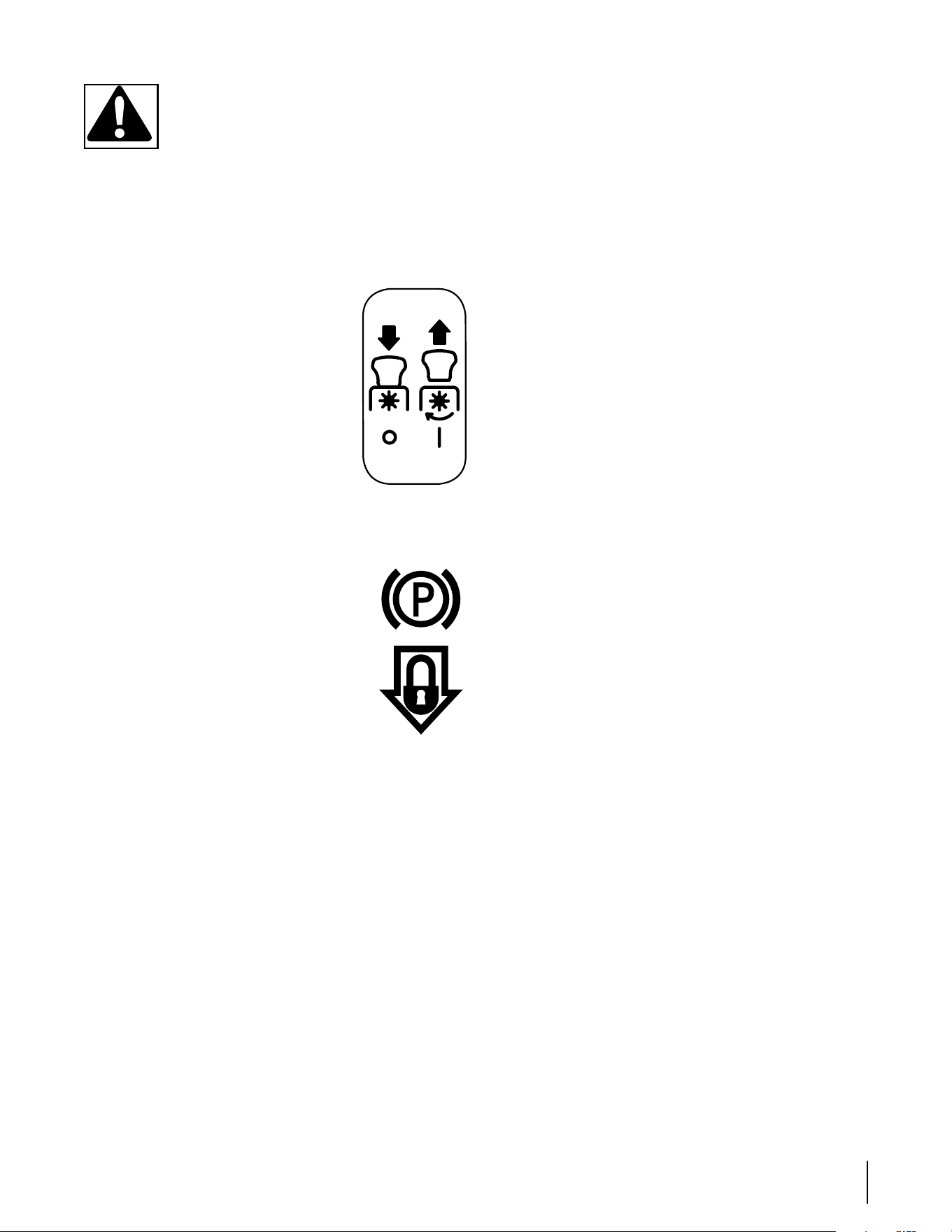
11sección 4— cOntrOles y características
ADVERTENCIA: Nunca mueva la llave a la
posición Start (Encendido) mientras el motor está
funcionando. Si lo hace, puede ocasionar daños al
arrancador del motor.
Control del obturador
la perilla de control del cebador se encuentra del lado inferior
izquierdo del panel de instrumentos, y se activa tirando hacia afuera.
Al activar el control del obturador se cierra la placa del obturador del
carburador y esto ayuda a arrancar el motor.
Interruptor de la potencia de arranque
(enganche de cuchilla)
Para conectar la potencia de arranque eléctrica
y suministrar energía a la plataforma de corte,
tire hacia afuera de la perilla del interruptor.
Presione la perilla del interruptor hacia adentro
para desconectar la potencia de arranque (PTO)
y detener la plataforma de corte.
NOTA: Al encender el motor, el interruptor de
control de la potencia de arranque (PTO) debe
encontrarse en la posición de desconexión
(OFF).
Palanca de freno de mano
NOTA: Si el operador abandona el asiento y deja el motor
funcionando, deberá colocar el freno de mano, o el motor se apagará
de forma automática.
• Para colocar el freno de mano, presione por
completo el pedal de freno y empuje la parte
inferior de la palanca del freno de mano hacia
adentro. vea en la imagen de la derecha las
identificaciones del freno de mano. Mantenga la
palanca hacia adentro mientras saca el pie del
pedal de freno. Tanto la palanca del freno como el
pedal quedarán presionados.
• Para soltar el freno de mano, presione ligeramente
el pedal del freno. la palanca del freno de mano
volverá a su posición original.
IMPORTANTE: Coloque siempre el freno de mano cuando deje el
tractor sin vigilancia.
Pedal de control de avance
El pedal de control de avance está ubicado en el lado derecho del
tractor, en la parte delantera del estribo derecho. Oprima el pedal
de control de avance para que el tractor se desplace hacia adelante.
la velocidad de marcha directa del tractor es afectada directamente
por cuánto se oprima el pedal. Cuanto más se presione el pedal,
más rápido se moverá el tractor. Cuando se suelta el pedal el tractor
reduce la velocidad y el pedal vuelve a su posición original.
Pedal de control de marcha atrás
El pedal de control de marcha atrás está ubicado en el estribo
delantero derecho detrás del pedal de control de avance. Oprima
el pedal de control de marcha atrás para que el tractor se desplace
hacia atrás. Cuanto más se presione el pedal, más rápido se moverá
el tractor. Cuando se suelta el pedal el tractor reduce la velocidad y el
pedal vuelve a su posición original.
Pedal de freno
El pedal de freno está ubicado en la parte delantera del estribo
izquierdo y se usa para detenerse rápidamente o para poner el freno
de mano. Se debe presionar TOTAlMENTE el pedal del freno para
activar el interruptor de bloqueo de seguridad al encender el tractor.
Palanca de elevación de la plataforma
la palanca de elevación de la plataforma se encuentra en el
guardabarros derecho y se usa para cambiar la altura de la plataforma
de corte. las alturas de corte oscilan entre 1-1/2” y 4”. Cada una de
las seis muescas indicadoras representa un ajuste aproximado de
1/2” en la altura de la plataforma. Para usarla, tome la manija de la
palanca de elevación y tire levemente hacia arriba y atrás mientras
pivota la palanca hacia adentro y afuera para desalojarla de la
muesca. Mueva la palanca de elevación lo necesario para colocarla
en la muesca que mejor se adapte a la aplicación deseada.
Después de cambiar la altura de corte de la plataforma, debe
inspeccionar la posición de las ruedas de calibración frontales de la
plataforma. Deberían estar aproximadamente a ½ pulgada del suelo
cuando el tractor se encuentra sobre una superficie lisa y plana como
una entrada para coches. Consulte la sección “Mantenimiento y
Ajustes” que está más adelante en este manual.
Portacubeta
El portacubeta del tractor se encuentra sobre el guardabarros a la
izquierda del asiento.
Palanca de ajuste del asiento
la palanca de ajuste del asiento está a la izquierda del asiento.
utilice esta palanca para ajustar el asiento hacia adelante o hacia
atrás hasta lograr una posición de operación cómoda. vea la sección
“Mantenimiento y Ajustes” más adelante en este manual donde
encontrará instrucciones.
Tapón de llenado de combustible y visor
del nivel de combustible
El tapón de llenado de combustible se encuentra en el centro del
guardabarros trasero. Gire el asiento hacia adelante para acceder
completamente al tapón de llenado de combustible y llenar el tanque.
Gire el tapón aproximadamente 1/4 de vuelta y tire hacia arriba para
extraerlo. Empuje el tapón hacia abajo sobre el cuello de llenado del
tanque de combustible y gire 1/4 de vuelta en sentido de las agujas
del reloj para ajustarlo.
Se puede ver el nivel de combustible que hay en el tanque a través
del visor del nivel de combustible de la placa de enganche trasera.
Red de carga
Convenientemente ubicada en el panel de instrumentos del tractor, la
red de carga se puede usar para guardar objetos personales mientras
se opera el tractor corta césped.
Varillas de derivación de transmisión
hidrostática
las varillas de derivación de transmisión hidrostática se encuentran
en la parte posterior del tractor, sobre la placa de enganche trasera.
Cuando están enganchadas, estas palancas abren la válvula de
derivación de una hidrobomba en cada transmisión, lo que permite
empujar manualmente el tractor en distancias cortas. vea la sección
“Mantenimiento y Ajustes” más adelante en este manual donde
encontrará instrucciones.
OFF
(apagado)
ON
(encendido)
PTO
(Potencia de arranque)
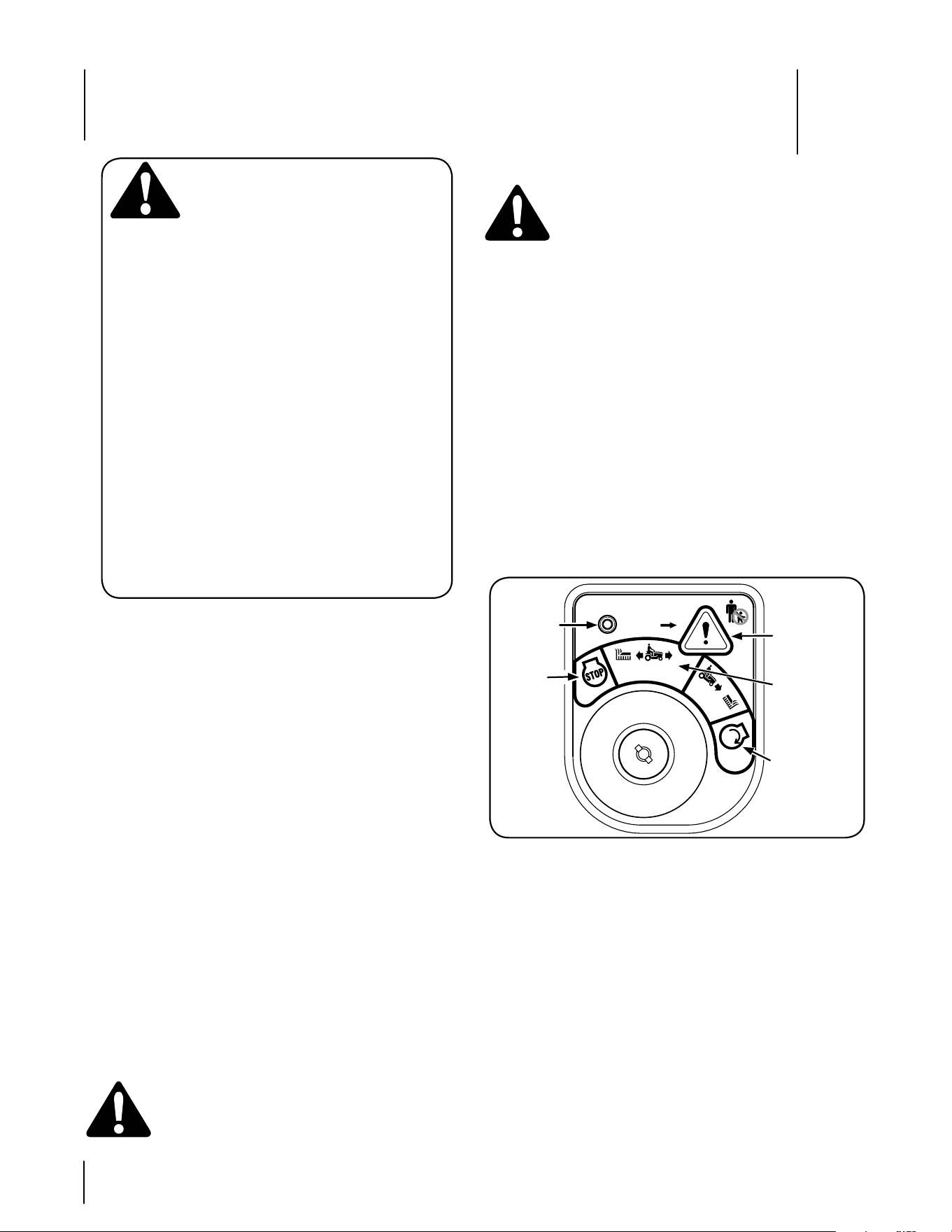
Faros delanteros
Los faros delanteros del tractor se prenden al girar el
interruptor de encendido a cualquiera de las posiciones de
encendido.
Sistema de bloqueo de seguridad
El sistema de bloqueo de seguridad está diseñado para que el
tractor funcione con seguridad. Si el sistema fallara en algún
momento, no haga funcionar el tractor, póngase en contacto
inmediatamente con el distribuidor de Cub Cadet.
El sistema de bloqueo de seguridad impide que el motor
arranque o se encienda a menos que esté colocado el freno
de mano, y el interruptor de potencia de arranque (PTO)
esté en posición desconectada (OFF).
Si el operador abandona su asiento antes de colocar el
freno de mano, el sistema de bloqueo de seguridad apaga
automáticamente el motor.
Si el operador abandona su asiento con el interruptor de la
potencia de arranque (enganche de cuchilla) conectado, el
sistema de bloqueo de seguridad apaga automáticamente
el motor, sin importar si el freno de mano está enganchado.
Con la llave de encendido en la posición de CORTE
NORMAL, el embrague de la potencia de arranque eléctrica
se desconecta automáticamente si el interruptor de la
potencia de arranque se encuentra en posición conectada
(ON) y el pedal de transmisión se presiona para la marcha
atrás.
ADVERTENCIA: Forzar o intentar evitar los
Interruptores de bloqueo de seguridad de
cualquier manera anulará la garantía de su tractor.
No opere el tractor si el sistema de bloqueo
funciona mal.
•
•
•
•
Modo de precaución en marcha atrás
ADVERTENCIA: Tenga mucho cuidado cuando
opere el tractor en MODO DE PRECAUCIÓN EN
MARCHA ATRÁS. Mire siempre hacia abajo y hacia
atrás antes y mientras opera marcha atrás. No
opere el tractor cuando haya niños u otras
personas en el lugar. Detenga el tractor
inmediatamente si alguien ingresa en la zona.
La posición MODO DE PRECAUCIóN EN MARCHA ATRÁS
del módulo del interruptor de llave permite operar el tractor
en marcha atrás con las cuchillas (potencia de arranque/PTO)
enganchadas.
IMPORTANTE: No se recomienda cortar el césped en marcha
atrás.
Para utilizar el MODO DE PRECAUCIóN EN
MARCHA ATRÁS:
IMPORTANTE: El operador DEBE estar sentado en el asiento
del tractor.
Arranque el motor como se indica en esta subsección del
manual.
Gire la llave desde la posición de PODA NORMAL (verde)
hasta la posición de MODO DE PRECAUCIÓN EN MARCHA
ATRÁS (amarillo) del módulo del interruptor de llave. Vea la
Figura 5-1.
1.
2.
Figura 5-1
Presione el BOTÓN DE MARCHA ATRÁS (botón triangular
de color naranja) en la esquina superior derecha del
módulo del interruptor de llave. La luz indicadora roja en
la esquina superior izquierda del módulo del interruptor
de llave se mantiene encendida (ON) mientras esté
activado. Vea la Figura 5-1.
Una vez activado (con la luz indicadora encendida), el
tractor podrá operar en marcha atrás con las cuchillas de
corte (PTO – potencia de arranque) enganchadas.
Siempre mire hacia abajo y hacia atrás antes y mientras
opera en marcha atrás, para asegurarse de que no haya
niños en el área.
Una vez retomada la marcha hacia adelante, vuelva a
colocar la llave en la posición CORTE NORMAL.
IMPORTANTE: El MODO DE PRECAUCIóN EN MARCHA
ATRÁS permanecerá activado hasta que:
a. Se coloca la llave en la posición CORTE NORMAL o en la
posición STOP (detención).
b. El operador abandona el asiento. Siga las instrucciones
anteriores para volver a activar.
3.
4.
5.
6.
ADVERTENCIA
EVITE LESIONES PERSONALES
GRAVES O LA MUERTE
• EN lAS PENDIENTES CONDuZCA HACIA ARRIBA Y HACIA ABAJO, NO DE
FORMA TRANSvERSAl.
• EvITE MANIOBRAS DE GIRO BRuSCAS.
• NO OPERE lA uNIDAD EN ÁREAS DONDE PuEDE DERRAPAR O
lADEARSE.
• SI lA MÁQuINA DEJA DE SuBIR lA PENDIENTE, DETENGA lAS
CuCHIllAS Y RETROCEDA lENTAMENTE BAJANDO lA PENDIENTE
• NO CORTE El CÉSPED CuANDO HAYA NIÑOS u OTRAS PERSONAS
CERCA.
• NuNCA TRANSPORTE NIÑOS, NI SIQuIERA SI lAS CuCHIllAS ESTÁN
DESCONECTADAS.
• MIRE HACIA ABAJO Y HACIA ATRÁS ANTES Y MIENTRAS OPERA EN
MARCHA ATRÁS.
• MANTENGA TODOS lOS DISPOSITIvOS DE SEGuRIDAD (PROTECCIONES,
ESCuDOS E INTERRuPTORES) EN Su luGAR Y EN CORRECTO
FuNCIONAMIENTO.
• RETIRE lOS OBJETOS QuE PuEDAN SER ARROJADOS POR lA(S)
CuCHIllA(S) EN CuAlQuIER DIRECCIóN.
• CONOZCA lA uBICACIóN Y FuNCIóN DE TODOS lOS CONTROlES.
• ASEGÚRESE DE QuE lAS CuCHIllAS Y El MOTOR SE DETENGAN ANTES
DE COlOCAR lAS MANOS O lOS PIES CERCA DE lAS CuCHIllAS.
• ANTES DE ABANDONAR lA POSICIóN DEl OPERADOR, DESENGANCHE
lAS CuCHIllAS, COlOQuE lA PAlANCA DE CAMBIOS EN POSICIóN
NEuTRAl, COlOQuE El FRENO DE MANO, APAGuE El MOTOR Y RETIRE
lA llAvE.
LEA EL MANUAL DEL OPERADOR
NO de haber niños alrededor
botón de marcha
atrás
N
O
R
M
A
L
encendido
M
A
R
C
H
A
A
T
R
Á
S
m
o
d
o
p
r
e
c
a
u
c
i
ó
n
c
o
r
t
e
d
e
c
é
s
p
e
d
Luz
indicadora
Posición
de
detención
Botón de
marcha atrás
Posición de
modo de
precaución en
marcha atrás
Posición de
arranque
Funcionamiento
5
12
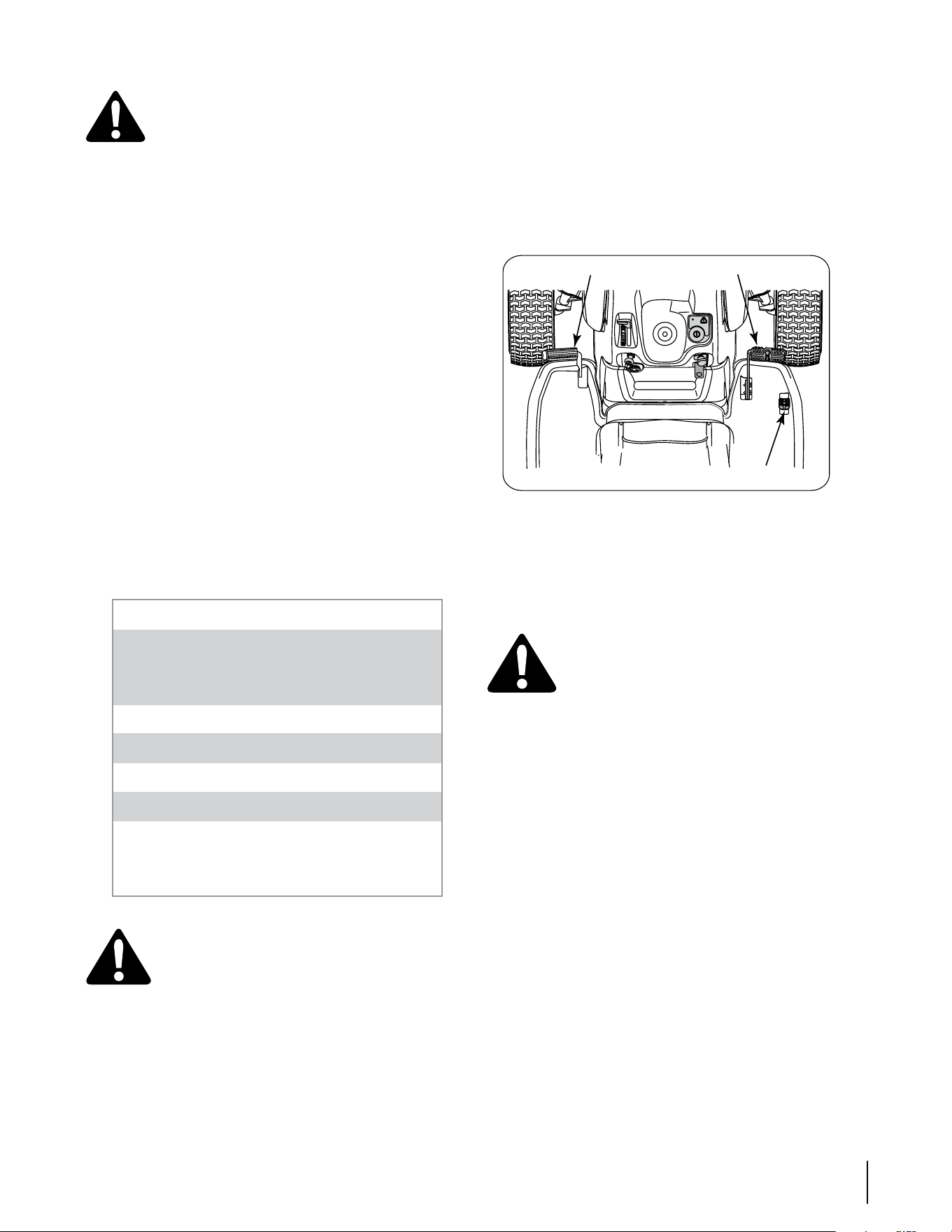
Encendido del motor
ADVERTENCIA: No opere el tractor si el sistema
de bloqueo funciona mal. El sistema fue diseñado
para brindarle seguridad y protección.
NOTA: Consulte el Manual del propietario del motor para ver
las instrucciones de llenado de gasolina y aceite..
Inserte la llave del tractor en el módulo del interruptor de
llave.
Desconecte la palanca/perilla de potencia de arranque
(enganche de cuchilla).
Coloque el freno de mano del tractor.
Tire de la perilla de control del cebador hacia afuera hasta
la posición de cebado completo (si el motor está caliente
puede no necesitar cebado).
Mueva la palanca de control del regulador al medio, entre
las posiciones DESPACIO y RÁPIDO .
Gire la llave de encendido en el sentido de las agujas del
reloj hasta la posición START (ENCENDIDO). Una vez que
arranque el motor, suelte la llave. Volverá a la posición de
CORTE NORMAL.
IMPORTANTE: No sostenga la llave en la posición START
(ENCENDIDO) durante más de diez segundos por vez. Si lo
hace, puede ocasionar daños al arrancador eléctrico del motor.
Una vez que arranque el motor, empuje gradualmente la
perilla del cebador totalmente hacia adentro a medida
que el motor se calienta.
NOTA: No utilice el cebador para enriquecer la mezcla de
combustible, excepto cuando sea necesario para arrancar y
calentar el motor.
1.
2.
3.
4.
5.
6.
7.
Conducción del tractor
IMPORTANTE: Evite arrancar súbitamente, desarrollar
excesiva velocidad y detenerse de repente.
Presione brevemente el pedal del freno para liberar
el freno de mano. Mueva la palanca del regulador a la
posición FAST (VELOCIDAD RÁPIDA, representada por una
liebre).
Para conducir hacia adelante: Presione lentamente el
pedal de transmisión hacia adelante hasta que se alcance
la velocidad deseada. Vea la Figura 5-2.
•
•
Detención del motor
ADVERTENCIA: Si golpea contra algún objeto
extraño, detenga el motor y desconecte
el(los) cable(s) de las bujías. Inspeccione
minuciosamente la máquina para ver si está
dañada. Repare el daño antes de volver a
arrancar el motor y operar la máquina.
Si las cuchillas están enganchadas, desconecte la potencia
de arranque.
Mueva la palanca de control del regulador al medio de las
posiciones mitad y completo del regulador. Luego gire la
llave de encendido en sentido contrario a las agujas del reloj a
la posición OFF (apagado).
Retire la llave del interruptor de encendido para evitar que
alguien encienda accidentalmente el motor.
1.
2.
3.
Figura 5-2
Para conducir hacia atrás: Verifique que el área detrás
esté despejada. Luego presione lentamente el pedal de
transmisión hacia atrás hasta que se alcance la velocidad
deseada. Vea la Figura 5-2.
Suelte el pedal de transmisión y presione el pedal del
freno para detener el tractor.
¡ADVERTENCIA! No abandone el asiento del
tractor sin colocar primero la perilla de PTO/
enganche de cuchilla en la posición de corte de
energía (OFF) y colocar el freno de mano. Si deja
el tractor sin vigilancia, apague el motor y retire
la llave de encendido.
Dirección del tractor
El tractor de la serie i1000 está equipado con un innovador
sistema de dirección. Al girar el volante no sólo giran las
ruedas delanteras, sino también se corrige la posición del
varillaje de transmisión de las dos transmisiones hidrostáticas
que impulsan el tractor. Este sistema de dirección le permite
variar el radio de giro desde un giro amplio normal en U
a un giro cero. Es posible que necesite practicar un poco
para acostumbrarse a la dirección de su tractor. La dirección
funciona de la siguiente manera:
El volante gira aproximadamente dos vueltas de un
tope a otro. La posición central es la posición recta hacia
adelante.
Pequeños giros del volante desde la posición central
(aproximadamente de 10º a 15º) harán girar sólo los ejes
delanteros y producirán curvas más amplias.
Al aumentar el giro del volante (más de 10°-15º) se cierra el
ángulo de las curvas. Mientras el mecanismo de dirección
hace girar las ruedas delanteras, también cambia la
posición del varillaje de la transmisión para decelerar
la rueda trasera interior durante las curvas y ajustar la
velocidad de la rueda exterior si fuera necesario para
completar la curva deseada. Vuelva el volante a la posición
central después de completar la curva.
•
•
•
•
•
Pedal de freno
Pedal de la transmisión hacia adelante
Pedal de la transmisión hacia atrás
IMPORTANTE
No abandone el asiento del tractor sin antes
Desconectar la palanca de potencia de arranque
(PTO)
Presionar el pedal del freno
Colocar el freno de mano
Si deja el tractor sin vigilancia, también gire la llave de
encendido a la posición off (apagado) y retírela.
Al conducir el tractor evite arrancar súbitamente,
desarrollar excesiva velocidad y detenerse bruscamente.
No corte el césped en pendientes de más de 15 grados
(elevación aproximada de 2-1/2 pies por cada 10 pies).
Mantenga las manos y los pies alejados de la abertura de
la plataforma de corte.
Planifique el patrón de corte para evitar que la descarga
de materiales se realice hacia los caminos, las veredas,
los observadores, etc. Evite además descargar material
contra las paredes u obstrucciones que podrían hacer
que el material descargado rebote contra el operador.
1.
2.
3.
13sección 5— funciOnaMientO

NOTA: No hace falta soltar el pedal de transmisión durante
las curvas. El cambio en el varillaje de transmisión ocurre sin
importar cuánto se está presionando el pedal de transmisión.
Al enderezar el volante, el tractor vuelve a la velocidad
indicada por el pedal de transmisión.
Al girar el volante hasta el tope en cualquier dirección,
las ruedas delanteras giran completamente, se invierte la
dirección de la rueda interna y se ajusta la velocidad de la
rueda externa para ejecutar un giro a cero en la dirección
elegida. Vuelva el volante a la posición central después de
completar la curva.
NOTA: A medida que se dobla el volante hacia el tope,
aumenta el esfuerzo necesario para hacer girar el volante.
IMPORTANTE: Las curvas cerradas sobre el césped aumentan
considerablemente las posibilidades de estropear la hierba.
Operación en pendientes
IMPORTANTE: Consulte la sección INDICADOR DE PENDIENTE
en la página 7 para determinar en qué pendientes puede
operar el tractor de manera segura.
Corte hacia arriba y abajo de las pendientes, nunca en
forma transversal.
Esté atento a los hoyos, surcos, baches, rocas u otros
objetos ocultos. El terreno desnivelado puede voltear la
máquina. El césped alto puede ocultar obstáculos.
Evite realizar giros cuando opere en una pendiente. Si
debe realizar un giro, gire cuesta abajo. Girar cuesta arriba
aumenta las posibilidades de volcar el tractor.
Evite detenerse cuando suba una pendiente. Si fuese
necesario detenerse mientras sube una pendiente,
arranque suave y cuidadosamente para reducir la
posibilidad de que el tractor dé una voltereta hacia atrás.
Colocación del freno de mano
NOTA: Si el operador abandona el asiento y deja el motor
funcionando, deberá colocar el freno de mano, o el motor se
apagará de forma automática.
Para colocar el freno de mano:
Presione el pedal del freno completamente hacia abajo
con el pie derecho y manténgalo en esa posición.
Empuje la palanca del freno de mano hacia abajo y
manténgala en esa posición.
Retire su pie del pedal de freno.
Afloje la presión de la palanca del freno de mano.
Después de completar el paso 3, el pedal de freno debe
permanecer en posición abajo. Si no lo hace, el freno de mano
no estáenganchado. Repita los pasos 1-4 para enganchar el
freno de mano.
Para desenganchar el freno de mano, presione levemente el
pedal de freno.
ADVERTENCIA: Nunca deje la máquina
en funcionamiento sin vigilancia. Siempre
desconecte la potencia de arranque (PTO),
coloque el freno de mano, apague el motor y
retire la llave, para evitar que alguien encienda
accidentalmente el motor.
•
•
•
•
•
1.
2.
3.
4.
Conexión de potencia de arranque (PTO)
Al conectar la potencia de arranque (PTO) se suministra
alimentación a la plataforma de corte o a otros accesorios
(disponibles por separado). Para conectar la PTO:
Mueva la palanca de control del regulador a la posición
FAST (VELOCIDAD RÁPIDA, representada por una liebre).
Tire de la perilla de la potencia de arranque (PTO)
(enganche de cuchilla) hacia afuera hasta la posición ON
(conectada).
NOTA: Haga funcionar el tractor siempre con la palanca
del regulador en la posición FAST (VELOCIDAD RÁPIDA;
representada por una liebre), para un uso más eficaz de la
plataforma de corte o de otros accesorios accionados por la
potencia de arranque (PTO) (disponibles por separado).
Corte de césped
ADVERTENCIA: Para ayudar a evitar el contacto
con las cuchillas o una lesión por algún objeto
que sea arrojado, mantenga a las personas que
lo observan, a los ayudantes, niños y mascotas
alejados al menos 25 metros de la máquina
mientras está en funcionamiento. Detenga la
máquina si alguien entra en la zona.
Este tractor está equipado con una de las plataformas de
corte de alta calidad de Cub Cadet. La siguiente información
será de utilidad cuando use la plataforma de corte con su
tractor.
No corte a alta velocidad absoluta, especialmente si se ha
instalado un juego de abonadora o un colector de césped.
Para obtener los mejores resultados, se recomienda realizar
los dos primeros cortes de césped arrojando la descarga hacia
el centro. Después de las dos primeras vueltas, cambie la
dirección para arrojar la descarga hacia afuera, para equilibrar
el corte. Esto otorgará un mejor aspecto al césped.
No corte el césped demasiado corto. El césped corto es
propicio para el crecimiento de malezas y se pone amarillo
rápidamente cuando escasea la lluvia.
El corte del césped siempre debe realizarse con el
regulador del motor al máximo.
En terrenos difíciles, puede resultar necesario pasar por
segunda vez el tractor corta césped sobre el área ya cortada,
para obtener un corte más prolijo.
No intente cortar malezas frondosas o césped
extremadamente alto. El tractor fue diseñado para cortar
el césped, no para podar malezas.
Mantenga las cuchillas afiladas, y reemplácelas cuando se
desgasten. Consulte la sección “SERVICIO” de este manual
para obtener instrucciones sobre cómo afilar correctamente
las cuchillas.
IMPORTANTE: Cuando detenga el tractor por cualquier
motivo sobre el césped, siempre
Coloque la palanca de cambios en neutral,
Coloque el freno de mano,
Apague el motor y retire la llave.
Eso permitirá reducir al mínimo la posibilidad de que su
césped resulte quemado por el escape caliente del motor en
funcionamiento.
1.
2.
•
•
•
•
•
•
•
•
•
•
14 sección 5— funciOnaMientO
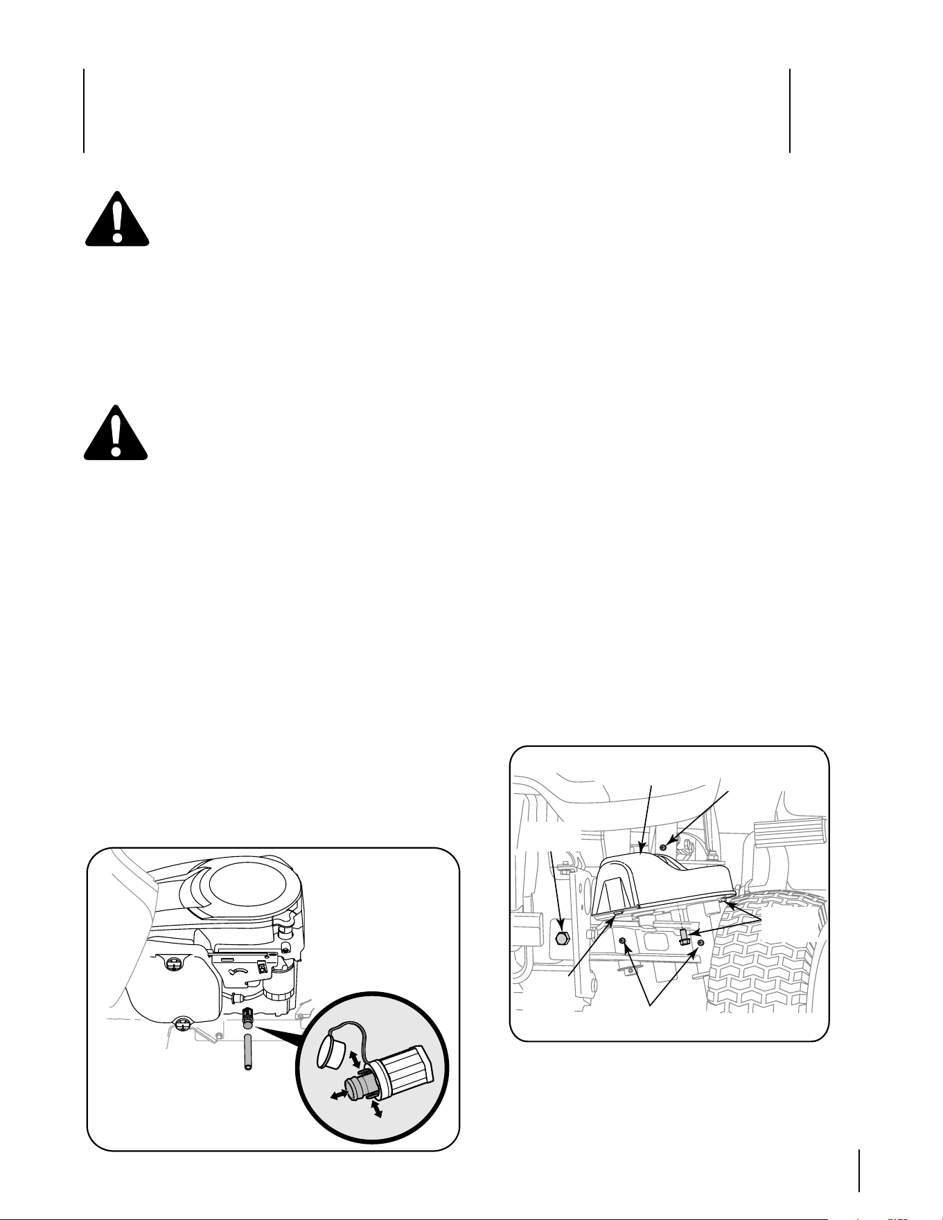
Mantenimiento y Ajustes
6
15
Mantenimiento
¡ADVERTENCIA! Antes de realizar tareas de
mantenimiento o reparaciones, desconecte la
potencia de arranque (PTO), mueva las palancas
de control totalmente hacia afuera hasta la
posición neutral, coloque el freno de mano,
apague el motor y retire la llave, para evitar el
encendido accidental del motor.
Motor
Consulte los intervalos, procedimientos, especificaciones e
instrucciones de mantenimiento del motor en el Manual del
Propietario/Operador Kohler.
Cambio de aceite del motor
¡ADVERTENCIA! Si el motor se ha puesto
en funcionamiento recientemente, el motor,
silenciador y las superficies metálicas circundantes
estarán calientes y pueden causar quemaduras a
la piel. Tenga precaución para evitar quemaduras.
Para completar el cambio de aceite, proceda de la siguiente
manera:
Haga funcionar el motor por un período corto para calentar el
aceite del motor. El aceite fluirá mejor y limpiará las impurezas.
Sea cuidadoso para evitar quemaduras con el aceite caliente.
Ubique el orificio de drenaje de aceite del lado izquierdo
del motor.
Abra el tapón protector en el extremo de la válvula
de drenaje de aceite para dejar expuesto el orificio de
drenaje. Consulte la Figura 6-1. Retire el tapón de llenado
de aceite /la varilla de nivel de aceite del tubo de llenado.
Inserte la manguera de drenaje de aceite (embalada con
este manual) dentro del orificio de drenaje de aceite.
Coloque el extremo opuesto de la manguera en un
recipiente adecuado de recolección de aceite que posea
una capacidad de por lo menos 2.0 cuartos de galón (2,4
litros) para recoger el aceite usado.
Apriete las lengüetas de la válvula de drenaje de aceite,
luego tire hacia afuera para comenzar a drenar el aceite.
Vea la Fig. 6-1.
Figura 6-1
1.
2.
3.
4.
5.
Después de que termine de drenar el aceite, empuje el
extremo de la válvula de drenaje de aceite hacia adentro,
hasta que las lengüetas encajen en su lugar haciendo clic.
Vuelva a tapar el extremo de la válvula de drenaje de aceite
para evitar que ingresen residuos en el orificio de drenaje.
Cambie el filtro de aceite y vuelva a cargar el motor
con aceite nuevo según las instrucciones del Manual
Propietario Kohler.
Depurador de aire
Realice el servicio de mantenimiento del prefiltro y del
elemento del depurador de aire/ cartucho según las
instrucciones del Manual del Propietario Kohler.
Bujía de encendido
Se debe limpiar las bujías y reajustar la separación una
vez por temporada. Consulte el tipo de bujía correcta y las
especificaciones de separación en el Manual del propietario
Kohler.
Transmisión hidrostática
El tractor con radio de giro cero está equipado con bombas
hidrostáticas integradas dobles / transejes que están sellados
y no necesitan mantenimiento. No se puede controlar el nivel
de líquido ni se puede cambiar ni agregar líquido.
Lubricación de la dirección
Se deben lubricar los brazos de mando, ejes de pivote y
ejes si aumenta el esfuerzo de la dirección, o cada 25 horas
de funcionamiento. Lubrique con una pistola de engrase a
presión y grasa Cub Cadet 251H EP, o una grasa equivalente
de litio multiuso No. 2.
Aplique grasa a través del accesorio lubricante de los
brazos de mando derecho e izquierdo que se encuentran
en el extremo posterior de las dos barras de acoplamiento
del volante. Vea la Figura 6-2.
6.
7.
•
Figura 6-2
Localice los accesorios de lubricación del eje de pivote
y eje al frente de uno de los extremos de la barra del eje
de pivote. Aplique grasa a través de los dos accesorios de
lubricación, luego repita para lubricar el otro extremo de
la barra. Vea la Figura 6-2.
•
Accesorio de
lubricación del
brazo de mando
Perno con
reborde
lengüeta
de la
cubierta
Accesorios de lubricación de
la barra del eje del pivote.
Tornillo
hexagonal
Cubierta del engranaje
de transmisión
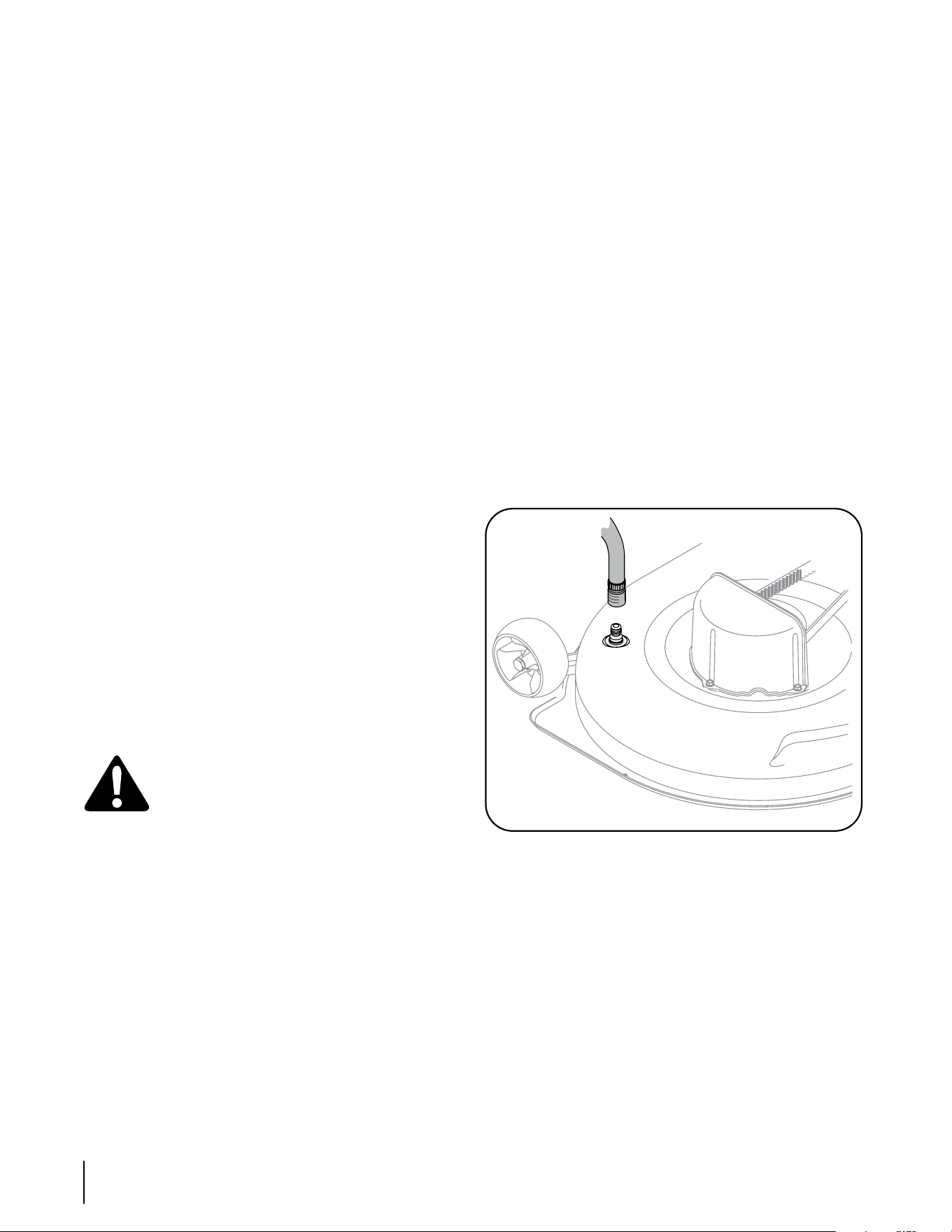
16 sección 6— ManteniMientO y ajustes
Limpieza de los engranajes de la dirección
Una vez al año, o si siente un punto ajustado al girar el volante,
retire la cubierta del engranaje de la dirección a cada extremo
de la barra de pivote y limpie los dos engranajes de la dirección.
Desde abajo de la placa de apoyo de la cubierta a cada
extremo de la barra de pivote, retire los tres tornillos
hexagonales que sujetan la cubierta del engranaje de la
dirección. Retire las cubiertas y limpie los engranajes. No
es necesario lubricar los engranajes. Vea la Figura 6-2.
Inserte la lengüeta de la cubierta del engranaje de la
dirección del lado izquierdo en el orificio cuadrado de la
placa de apoyo izquierda, coloque la cubierta, y asegure
con los tres tornillos hexagonales. No ajuste demasiado.
Repita para instalar la cubierta del lado derecho.
Lubrique los rodamientos de las ruedas delanteras
Lubrique los rodamientos de las ruedas delanteras con
grasa Cub Cadet 251H EP cada 25 horas de operación. Los
accesorios de lubricación se encuentran en la llanta dentro de
cada rueda delantera.
Lubrique los husillos y la ménsula intermedia de la plataforma
Lubrique los husillos y la ménsula intermedia de plataforma
con grasa Cub Cadet 251H EP cada 10 horas de operación.
Los accesorios de lubricación de los husillos de plataforma están
en los alojamientos de los husillos, y sólo se puede acceder
a ellos por debajo de la plataforma. Lubrique la ménsula
intermedia con el accesorio de lubricación ubicado en la parte
superior del perno con reborde. Use una pistola de engrase a
presión para lubricar los husillos y la ménsula intermedia.
Lubrique los puntos de pivote y el varillaje
Lubrique todos los puntos de pivote del sistema de impulsión,
el freno de mano y el varillaje de elevación al menos una vez
por temporada con aceite ligero.
Lubrique las ruedas traseras
Las ruedas traseras se deben sacar de los ejes una vez por
temporada. Lubrique bien los ejes y las llantas con una grasa
todo uso antes de reinstalarlos.
Neumáticos
ADVERTENCIA: Nunca exceda la presión máxima
de inflado que se indica en los laterales de los
neumáticos. Consulte los laterales de las ruedas
para conocer con exactitud la presión máxima en
psi recomendada por el fabricante. No los infle en
exceso.
La presión operativa recomendada para los neumáticos es:
Aproximadamente 10 psi para los neumáticos traseros
Aproximadamente 14 psi para los neumáticos delanteros
IMPORTANTE: Una presión de neumáticos despareja podría
hacer que la plataforma corte el césped en forma desigual.
Limpieza del tractor y de la plataforma
Si se derrama combustible o aceite sobre la máquina, debe
limpiarse de inmediato. NO permita que se acumulen
desechos alrededor de las poleas de la plataforma ni en
ninguna otra parte de la máquina.
Periódicamente retire las cubiertas de la correa y retire los
recortes de césped que se hayan acumulado alrededor de las
poleas del husillo y de la correa de la plataforma.
IMPORTANTE: NO se recomienda el uso de una lavadora de
presión para limpiar el tractor. Puede dañar los componentes
eléctricos, los husillos, las poleas, los rodamientos o el motor.
•
•
•
•
Uso del sistema Deck Wash System™
Utilice el sistema Deck Wash System™ para lavar la parte
inferior de la plataforma y quitar los restos de césped
recortado e impedir la acumulación de sustancias químicas
corrosivas. El tractor está equipado con una boquilla de agua
que está en el extremo izquierdo de la plataforma.
Realice los siguientes pasos DESPUÉS DE CADA CORTE DE
CÉSPED:
1. Dirija el tractor a una zona nivelada y despejada del
césped, que se encuentre suficientemente cerca de una
espiga de agua al alcance de la manguera del jardín.
IMPORTANTE: Asegúrese de que el canal de descarga del
tractor NO ESTÉ ORIENTADO EN LA DIRECCIÓN en que se
encuentran la casa, el garaje, los vehículos estacionados, etc.
2. Desconecte la potencia de arranque (enganche de
cuchilla), coloque el freno de mano y detenga el motor.
3. Enrosque el acople de boquilla (embalado con el Manual
del Operador de su tractor) en el extremo de la manguera
de jardín.
4. Tire hacia atrás el collarín de ajuste del acople de la
boquilla y empuje el adaptador hacia la boquilla de
lavado de la plataforma en el extremo izquierdo de la
plataforma de corte. Suelte el collarín de ajuste para trabar
el adaptador en la boquilla. Vea la Figura 21.
Figura 6-3
5. Abra el suministro de agua.
6. Mientras está sentado en la posición del operador del
tractor, vuelva a arrancar el motor y coloque la palanca
del regulador en la posición FAST (VELOCIDAD RÁPIDA,
representada por una liebre).
7. Mueva la potencia de arranque (enganche de cuchilla)
del tractor a la posición ON (enganchada). Permanezca
en la posición del operador con la plataforma de corte
enganchada durante dos minutos como mínimo,
permitiendo que el lado inferior de la plataforma de corte
se lave a fondo.
8. Mueva la potencia de arranque (enganche de cuchilla) del
tractor a la posición OFF (desenganchada). Gire la llave de
encendido a la posición STOP (detención) para apagar el
motor del tractor.
9. Tire del collarín de ajuste del adaptador de la boquilla
hacia atrás para desconectar el adaptador de la boquilla.
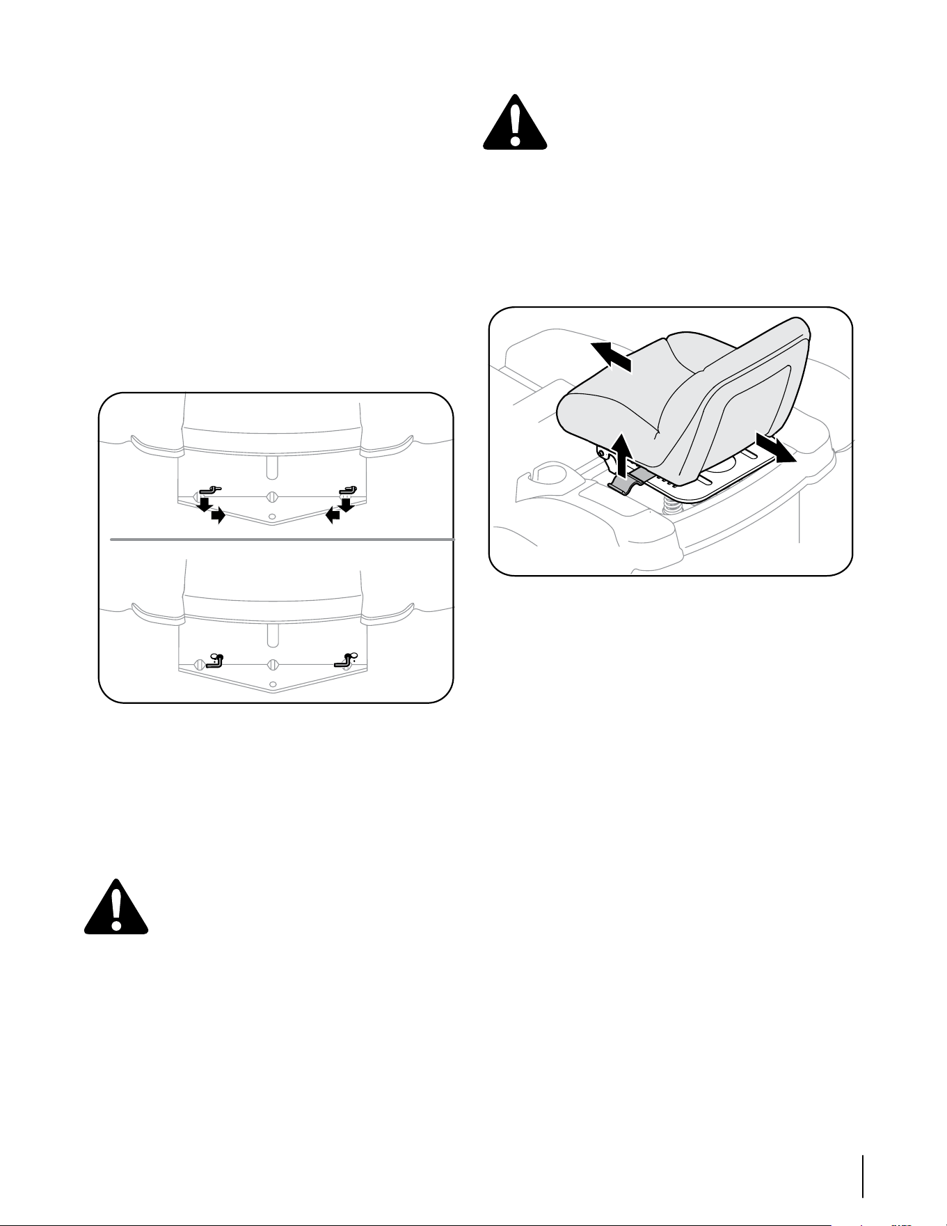
17sección 6— ManteniMientO y ajustes
Ajuste del asiento
ADVERTENCIA: Después de ajustar el asiento o
antes de conducir el tractor, asegúrese de que la
palanca de ajuste del asiento está enganchada en
la placa divisora del asiento y que el asiento no se
moverá. No ajuste el asiento mientras el tractor
está en movimiento. Ajustar el asiento mientras
el tractor está en movimiento puede hacer que el
operador pierda el control del tractor.
Siéntese en el asiento, tome la palanca de ajuste que
está del lado izquierdo del asiento y tire hacia arriba para
desengancharla de la placa divisora del asiento. Vea la
Figura 6-5.
Figura 6-5
Deslice el asiento a la posición deseada. Vea la Figura 6-5.
Una vez alcanzada la posición deseada, suelte la palanca.
Deslice el asiento levemente hacia atrás y adelante lo
necesario para enganchar la palanca del asiento en una
de las ocho posiciones de ajuste de la placa divisora.
Asegúrese de que el asiento se encuentra inmovilizado en
su posición.
Nivelación lado a lado de la plataforma
NOTA: Controle la presión de neumáticos del tractor antes
de realizar cualquier nivelación de la plataforma. Consulte
“Neumáticos” que está ubicado antes en esta sección si desea
información sobre la presión de los neumáticos.
Si la plataforma de corte estuviera realizando el corte de
césped de forma despareja, puede realizarse un ajuste lado
a lado. De ser necesario, realice un ajuste de la siguiente
manera:
Con el tractor aparcado en una superficie firme y plana,
mueva la plataforma a la posición de media altura
(tercera o cuarta muesca) usando la palanca de elevación
de la plataforma. Gire la cuchilla izquierda de manera
que quede perpendicular al bastidor del tractor. Mida y
registre la distancia desde el exterior de la punta de la
cuchilla izquierda hasta el suelo.
Pase al otro costado del tractor y gire la cuchilla derecha
de manera que quede perpendicular al bastidor del
tractor y mida la distancia desde la punta de su cuchilla
exterior hasta el suelo
Las dos mediciones obtenidas deben ser iguales. Si no lo
son, observe si el lado izquierdo de la plataforma está más
alto o más bajo y pase al siguiente paso.
1.
2.
3.
1.
2.
3.
Movimiento manual del tractor
Si por algún motivo el tractor no se puede conducir o
desea moverlo, enganche las dos varillas de derivación de
transmisión hidrostática para mover el tractor manualmente
distancias cortas.
IMPORTANTE: Nunca remolque o arrastre el motor con las
ruedas traseras tocando el suelo. NI aun con las varillas de
derivación enganchadas. Hacerlo dañará la transmisión.
Para enganchar una varilla de derivación, tire de la varilla
hacia atrás de manera que la brida de la varilla pase a través
de la abertura circular más grande del ojo de la llave. Después
de pasar la brida de la varilla hacia afuera (hacia atrás) de la
placa de enganche, empuje la varilla hacia adentro en la parte
más pequeña de la abertura del ojo de la llave de manera que
la brida de la varilla quede trabada contra la parte posterior
de la placa de enganche. Repita este paso para enganchar
la otra varilla de derivación para permitir el desplazamiento
manual del tractor. Vea la Figura 6-4.
Figura 6-4
Para desenganchar las varillas, muévalas para alinear su brida
con la parte más grande y circular de la abertura del ojo de la
llave y suelte la varilla para que pase nuevamente a través de
la placa de enganche.
NOTA: La transmisión NO se engancha cuando la varilla de
derivación hidrostática se tira hacia fuera. Regrese la varilla a
su posición normal antes de operar el tractor.
Ajustes
ADVERTENCIA: Nunca intente hacer ajustes
mientras el motor está en marcha, excepto
cuando así lo especifica el manual del operador.
Desconecte los cables de las bujías antes
de realizar cualquier ajuste, reparación o
mantenimiento.
Varillaje de dirección y transmisión
Las barras de acoplamiento de las ruedas motrices y el
varillaje de transmisión asociado se instalan en fábrica
y no debería requerir ajustes adicionales. Debido al
complejo procedimiento de ajuste, el varillaje de dirección
y transmisión sólo debe ser revisado o ajustado únicamente
por un mecánico calificado. Si tiene problemas con la
dirección o con la transmisión hidrostática, póngase en
contacto con su distribuidor Cub Cadet más cercano para que
inspeccione el tractor.
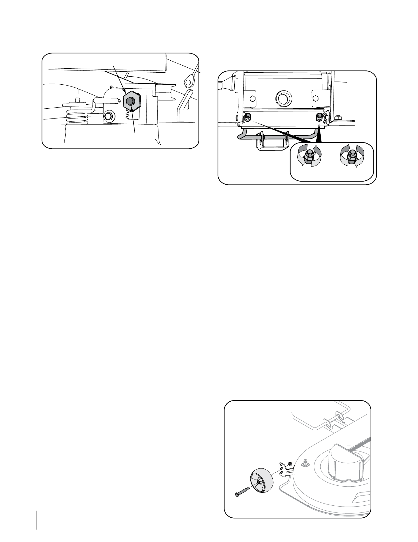
18 sección 6— ManteniMientO y ajustes
Desde el lado izquierdo del tractor, afloje sin quitar, el
tornillo hexagonal de la ménsula de ajuste izquierda de la
plataforma. Vea la Figura 6-6.
Figura 6-6
Para nivelar la plataforma gire el mecanismo de ajuste,
ubicado inmediatamente detrás del tornillo hexagonal, en
sentido de las agujas del reloj (hacia atrás) para bajar el lado
izquierdo de la plataforma. Gire el mecanismo en sentido
contrario a las agujas del reloj (hacia adelante) para levantar
el lado izquierdo de la plataforma. Vea la Figura 6-6.
La plataforma se encuentra correctamente equilibrada
cuando las dos mediciones de las puntas de las cuchillas,
como se explicó anteriormente, son iguales.
Una vez alcanzado el ajuste necesario, vuelva a ajustar
el tornillo de cabeza hexagonal de la ménsula de ajuste
izquierda de la plataforma.
Nivelación frontal-posterior de la plataforma
El frente de la plataforma de corte se apoya en una varilla de
suspensión frontal de la plataforma. Esta varilla se puede ajustar
para fijar la inclinación frontal-posterior de la plataforma. La
parte frontal de la plataforma debe estar aproximadamente ¼
de pulgada más abajo que la parte posterior. De ser necesario,
realice un ajuste de la siguiente manera:
NOTA: La plataforma se debe nivelar primero de forma
lateral. Verifique que la forma esté nivelada lateralmente y
realice los ajustes necesarios.
Con el tractor aparcado en una superficie firme y plana,
mueva la plataforma a la posición de media altura (tercera
o cuarta muesca) usando la palanca de elevación de la
plataforma. Rote cuidadosamente la cuchilla derecha (la
más cercana al canal de descarga) de manera que quede
paralela al bastidor del tractor.
Mida la distancia desde la parte delantera de la punta de
la cuchilla hasta el piso, y desde la parte posterior de la
punta de la cuchilla hasta el piso. La medida tomada en
el frente debería ser aproximadamente 1/4” menor que
la medida posterior. Determine si es necesario levantar o
bajar el frente de la plataforma.
Desde el frente del tractor, afloje las dos tuercas de
seguridad hexagonales de la parte delantera de la varilla
de suspensión frontal de la plataforma. Rosque las tuercas
de seguridad alejándolas de las tuercas hexagonales que
están detrás. Vea la Figura 6-7.
Utilice una llave de boca para girar las tuercas
hexagonales interiores a fin de ajustar la parte delantera
de la plataforma. Gire las tuercas hexagonales en
sentido de las agujas del reloj para levantar el frente de
la plataforma, o en sentido contrario para bajar el frente
de la plataforma. Ajuste las tuercas de forma pareja para
4.
5.
6.
7.
1.
2.
3.
4.
que la varilla de suspensión de la plataforma se encuentre
delante de ambas ranuras en la ménsula de suspensión
del frente de la plataforma. Vea la Figura 6-7.
Vuelva a afirmar las dos tuercas de seguridad
hexagonales cuando haya ajustado correctamente.
Figura 6-7
Ajuste de las ruedas calibradoras de la plataforma
NOTA: Las ruedas calibradoras de la plataforma tienen una
función anti-desbroce y no están diseñadas para soportar el
peso de la plataforma de corte.
Las ruedas calibradoras de la plataforma no deberían estar en
contacto con el suelo ni demasiado lejos del suelo, cuando se
coloca la plataforma a la altura deseada. Si cambia de altura
de corte durante la temporada, se deben revisar las ruedas
calibradoras y ajustarlas si es necesario. Ajuste las ruedas
calibradoras de la siguiente manera:
• Coloque el tractor en una superficie plana y mueva la
plataforma a la altura de corte deseada usando la palanca
de suspensión de la plataforma.
• Inspeccione la distancia de las ruedas calibradoras a la
superficie plana del suelo. Si las ruedas calibradoras tocan
el suelo, se las debe levantar. Si las ruedas calibradoras
están a más de 1/2” sobre el suelo, se las debe bajar.
• Extraiga la tuerca de seguridad bridada hexagonal y el perno
con reborde que sujetan una de las ruedas esféricas delanteras
a la ménsula divisora del frente. Reposicione la rueda esférica
para alinearla con uno de los cinco orificios de posicionamiento
que colocan a la rueda 1/4” a 1/2” por encima del suelo. Sujete
la rueda esférica a la ménsula divisora con el perno con reborde
y la tuerca de seguridad bridada. Tome nota del orificio de
posicionamiento utilizado y sujete la otra rueda esférica en la
misma posición. Vea la Figura 6-8.
Figura 6-8
5.
Mecanismo de ajuste
Tornillo hexagonal
Bajar frente
de plataforma
Subir frente
de plataforma

19sección 6— ManteniMientO y ajustes
Calendario de mantenimiento
Antes de
cada uso
Cada 10
horas
Cada 25
horas
Cada 50
horas
Cada 100
horas
Antes
de almacenar
Limpie el capó/los respiraderos
P P
Inspeccione el nivel de aceite del motor
P
Controle el filtro de aire para ver si hay piezas
sucias, sueltas o dañadas
P
Limpie y vuelva a lubricar el depurador de
espuma del filtro de aire
P
Reemplace el elemento del filtro de aire
P
Cambie el aceite del motor y reemplace el filtro
de aceite
P
Limpie los bornes de la batería
P P
Lubrique los brazos de mando intermedios,
ejes del pivote y ejes
P P
Lubrique los rodamientos de las ruedas
delanteras
P P
Limpie las aletas de refrigeración del motor
P P
Lubrique las ruedas delanteras de la plataforma
P P
Lubrique los husillos y la ménsula intermedia de
la plataforma
P P
Lubrique los puntos de pivote del pedal
P
Inspeccione el estado de la bujía de encendido y
la separación
P P
Reemplace el filtro de combustible
P

Servicio
7
20
Ajuste de la barra de pivote
Si el volante tiene demasiado juego, inspeccione el
movimiento hacia adelante y hacia atrás de la barra de pivote.
Levante el frente del tractor y póngalo sobre gatos, para
que las ruedas delanteras queden suspendidas en el aire.
Tomando los extremos de la barra de pivote, intente
mover cada extremo del eje hacia adelante y hacia atrás
para verificar el juego lateral. El juego lateral debe ser
mínimo o inexistente.
Si no hay juego lateral, baje el tractor al suelo y haga que
su distribuidor Cub Cadet inspeccione el varillaje de la
transmisión de dirección. Si hay juego lateral, ajuste la
barra de pivote de la siguiente manera:
Apoye la barra de pivote, luego extraiga las tuercas de
seguridad hexagonales que sujetan los dos pernos con
reborde que pasan a través de la ménsula de la barra de
pivote, la barra de pivote, y el bastidor. Vea la Figura 6-2.
Deslice una arandela plana de media pulgada, con un
espesor máximo de 0,030 pulgada, sobre cada perno
con reborde. Reinstale los pernos con reborde con las
arandelas y ajústelos con las dos tuercas de seguridad
hexagonales.
Ajuste la tuerca de seguridad hexagonal en forma
gradual y pareja mientras continúa controlando el
movimiento hacia atrás y adelante de la barra de
pivote. Ajuste las tuercas de seguridad hasta lograr que
el juego sea mínimo, sin comprometer el movimiento
hacia arriba y abajo de la barra de pivote.
Control del fusible del mazo de cables principal
En el mazo de cables de su tractor hay instalado un fusible
de 20 amperes, que protege el sistema eléctrico del tractor
de los daños causados por exceso de amperaje.
Si el sistema eléctrico no funciona, o el motor de su tractor
no arranca, verifique primero que el fusible no se haya
quemado.
El fusible se encuentra dentro del panel de instrumentos
detrás de la bandeja de la batería. Es posible que deba
extraer la batería para tener acceso al fusible. Para el
reemplazo utilice siempre un fusible que posea la misma
capacidad de amperaje.
NOTA: También se puede encontrar un segundo portafusibles
dentro del panel de instrumentos. Este portafusibles se usa
para la salida de potencia opcional de 12 voltios.
Batería
La batería está sellada y no necesita mantenimiento. Los
niveles de ácido no se pueden controlar.
Siempre mantenga limpios y libres de acumulación de
elementos corrosivos los cables y los bornes de la batería.
Después de limpiar la batería y los bornes, aplique una
capa delgada de vaselina o grasa a ambos bornes.
Siempre mantenga los capuchones de goma colocados
sobre el borne positivo para prevenir un cortocircuito.
IMPORTANTE: Si por alguna razón extrae la batería,
desconecte, desconecte primero el cable NEGATIVO (Negro) de
1.
2.
3.
•
•
•
•
•
•
•
•
•
su BORNE, y a continuación el cable POSITIVO (rojo). Cuando
vuelva a instalar la batería, conecte siempre primero el cable
POSITIVO (rojo) a su borne, y a continuación el cable NEGATIVO
(negro). Asegúrese de que los cables estén conectados a los
bornes correctos, ya que si los cambia se podría invertir la
polaridad y dañar el sistema alternador del motor.
Carga de la batería
Si no se ha utilizado el tractor por un periodo prolongado,
cargue la batería con un cargador de 12 voltios del tipo de
los utilizados en los automóviles, durante un mínimo de una
hora, a seis amperes.
ADVERTENCIA: Al cargarse, las baterías emiten
un gas que puede causar explosiones. Cargue
la batería en un área bien ventilada, y aléjela de
una llama abierta o luz piloto, como por ejemplo
calentadores de agua, calefactores de ambiente,
hornos, secadores de ropa u otros aparatos a gas.
Limpieza de la batería
Limpie la batería retirándola del tractor y lavándola con
bicarbonato de sodio y solución de agua. Si es necesario,
raspe los bornes de la batería con un cepillo de alambre para
quitar los depósitos. Cubra los bornes y los cables expuestos
con grasa o vaselina para prevenir la corrosión.
Desperfectos de la batería
Algunas causas comunes de falla de la batería son:
• activación inicial incorrecta • carga insuficiente
• carga excesiva • conexiones corroídas
• congelamiento
Estas fallas NO están cubiertas por la garantía del tractor.
Cambio de la correa de transmisión
NOTA: Para cambiar la correa de transmisión del tractor,
se deben retirar y reajustar varios componentes, incluido el
varillaje de la transmisión de dirección. Solicite a su distribuidor
de Cub Cadet que le realice el reemplazo de la correa.
Transmisión hidrostática
Mantenga el área alrededor del ventilador de enfriamiento
de la transmisión libre de pasto y residuos en todo momento.
La transmisión hidrostática viene sellada de fábrica y no tiene
mantenimiento alguno. No se puede controlar ni se puede
cambiar el nivel de líquido.
Almacenamiento fuera de temporada
Si la máquina va a estar inactiva por más
de 30 días, se recomiendan los siguientes
procedimientos:
ADVERTENCIA: Nunca almacene la máquina o el
recipiente de combustible en un espacio cerrado
donde haya llamas expuestas, chispas o una luz
piloto como por ejemplo, de calentadores de agua, hornos,
secadores de ropa u otros aparatos a gas.
IMPORTANTE: El combustible que queda en el tanque
cuando hace calor se deteriora y ocasiona graves problemas
de encendido.
Para evitar que se formen depósitos de goma dentro del
carburador del motor y posibles desperfectos en el motor, el
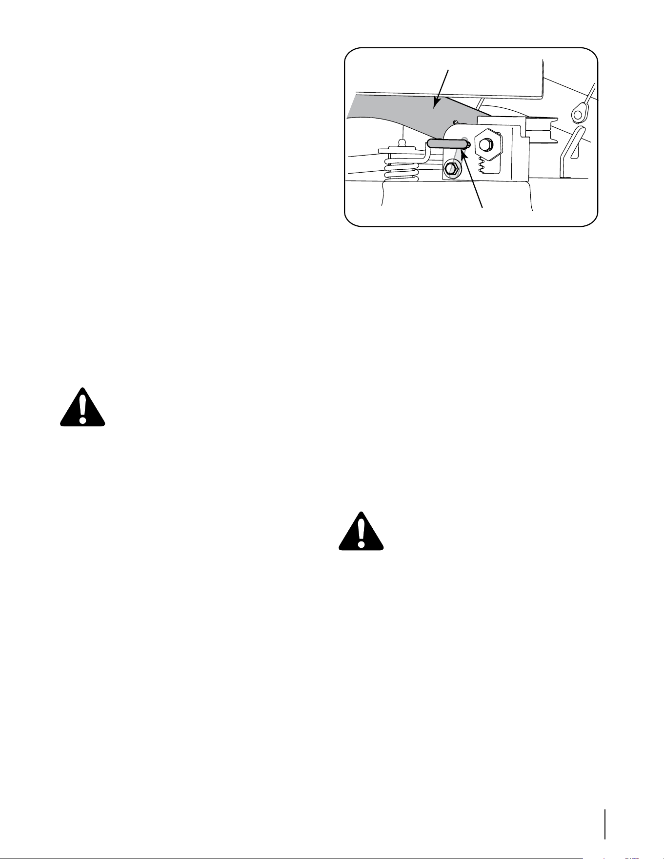
21sección 7— serviciO
sistema de combustible debe ser vaciado completamente, o
se debe tratar la gasolina con un estabilizador para evitar el
deterioro.
Si utiliza un estabilizador de combustible:
Lea las instrucciones y recomendaciones del fabricante
del producto.
Agregue la cantidad correcta de estabilizador para
la capacidad del sistema de combustible a gasolina
limpia y nueva.
Llene el depósito de combustible con combustible
tratado y haga funcionar el motor 2-3 minutos para
estabilizar el combustible dentro del carburador.
Cuando vacíe el sistema de combustible:
No drene el combustible cuando el motor está
caliente. Permita que el motor se enfríe bien. Drene el
combustible dentro de un recipiente aprobado y al aire
libre, lejos de cualquier llama expuesta.
Drene un gran volumen de combustible desde el
depósito, desconectando la línea de combustible del
filtro de combustible en línea que se encuentra cerca
del motor.
Vuelva a contectar la línea de combustible y haga
funcionar el motor hasta que comience a fallar, use
entonces el cebador para mantener el motor en marcha
hasta agotar todo el combustible del carburador.
Vuelva a desconectar la línea de combustible y drene
la gasolina restante en el sistema.
ADVERTENCIA: Drene el combustible
únicamente dentro de un recipiente aprobado
y al aire libre, lejos de cualquier llama expuesta.
Deje que el motor se enfríe. Antes de drenar el
combustible, apague cigarrillos, cigarros, pipas y
otras fuentes de combustión.
Extraiga la bujía y vierta una (1) onza de aceite para motor por
el orificio de la bujía en el cilindro. Haga girar el motor varias
veces para distribuir el aceite. Vuelva a colocar la bujía.
Anters de almacenar el tractor por un período prolongado,
límpielo y lubríquelo como se indica en la sección
“Mantenimiento y ajustes”.
Extracción de la plataforma de corte
Para extraer la plataforma de corte, proceda de la siguiente
manera:
Desconecte la potencia de arranque (enganche de
cuchilla) y coloque el freno de mano.
Coloque las ruedas de calibración de la plataforma en su
posición más alta (punto más bajo de la plataforma).
Baje la plataforma colocando la palanca de elevación
de la plataforma dentro de la muesca inferior en el
guardabarros derecho.
Mirando la plataforma de corte desde el lado izquierdo
del tractor, localice el pasador de soporte de la plataforma
ubicado en el lateral posterior izquierdo de la plataforma.
Vea la Figura 7-1.
Tire hacia afuera el pasador de soporte de la plataforma
para separar la misma del brazo de elevación de la
plataforma. Gire la manija del pasador de soporte
hacia abajo para trabar el pasador en la posición
desenganchada. Vea la Figura 7-1.
Córrase al lado derecho del tractor y repita el paso anterior
para soltar la plataforma del brazo de elevación derecho.
1.
•
•
•
2.
•
•
•
•
1.
2.
3.
4.
5.
6.
Figura 7-1
Mueva la palanca de elevación de la plataforma dentro de la
muesca superior del guardabarros derecho para levantar los
brazos de elevación de la plataforma y retirarlos del paso.
Deslice cuidadosamente la plataforma de corte hacia
adelante hasta que pueda retirar la varilla de suspensión
frontal de la plataforma de las ranuras de la ménsula de
suspensión frontal de la plataforma.
La correa de la potencia de arranque (PTO) es capturada
por un guardacorrea en el interior de la polea de la
potencia de arranque en la base del motor. Desde abajo
del lateral delantero/ izquierdo del tractor, ubique el
tornillo autoroscante hexagonal que sujeta el costado
izquierdo del guardacorrea a la base del marco del tractor.
Después de ubicar primero el orificio del marco en el
cual se inserta el lado derecho del guardacorrea, saque el
tornillo autoroscante hexagonal y el guardacorrea. Deslice
la correa de la potencia de arranque (PTO) fuera de la
polea de la potencia de arranque del tractor.
Mientras sostiene la varilla de suspensión frontal de
la plataforma hacia arriba para pasar la ménsula de
suspensión frontal de la plataforma, deslice la plataforma
con cuidado hacia afuera por el lado derecho del tractor.
Cuchillas de corte
ADVERTENCIA: Antes de extraer las cuchillas de
corte para afilarlas o reemplazarlas asegúrese de
apagar el motor, retirar la llave de encendido y
desconectar los cables de las bujías para evitar
el encendido accidental del motor. Protéjase las
manos utilizando guantes gruesos o un trapo para
asir la cuchilla de corte
Las cuchillas se pueden extraer de la siguiente manera.
Extraiga la plataforma de la parte inferior del tractor,
(consulte la sección Extracción de la plataforma de corte);
luego voltee con delicadeza la plataforma para dejar al
descubierto su parte inferior.
NOTA: Se puede colocar un bloque de madera entre el
alojamiento de la plataforma y el borde de corte de la cuchilla
para ayudar a aflojar la tuerca hexagonal que fija la cuchilla.
Use una llave de 15/16” para extraer la tuerca de brida
hexagonal que sujeta la cuchilla a la base del conjunto del
husillo. Asegure el husillo sujetando firmemente la cuchilla
o usando una segunda llave para sostener la tuerca de la
parte superior del husillo.
Continúe sosteniendo la cuchilla contra el cubo en estrella
del husillo y extraiga la tuerca de brida y la cuchilla de corte.
Repita los pasos anteriores para sacar la otra cuchilla.
Para afilar las cuchillas de corte de forma adecuada,
extraiga cantidades iguales de metal de ambos extremos
6.
7.
8.
9.
•
•
•
•
•
Brazo de elevación de la plataforma
Pasador de soporte de la plataforma
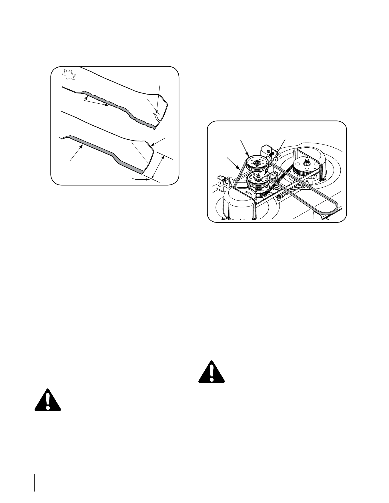
22 sección 7— serviciO
de las cuchillas a lo largo de los bordes cortantes, de forma
paralela al borde de caída, a un ángulo de 25° a 30°.
IMPORTANTE: Si el borde de corte de la cuchilla ya ha sido
afilado hasta 1 5/8” del borde, o si existe una separación de
metal, reemplace las cuchillas por otras nuevas. Vea la Figura 7-2.
Figura 7-2
Es importante que cada borde de la cuchilla de corte sea
pulido por igual para mantener el equilibrio adecuado de
la cuchilla.
Una cuchilla desequilibrada causará vibración excesiva
y puede ocasionar daños materiales al tractor y lesiones
personales. Se puede probar la cuchilla balanceándola
sobre un destornillador de eje circular. Afile el metal del
lado pesado hasta que quede bien equilibrada.
IMPORTANTE: Cuando reemplace las cuchillas, asegúrese
de instalarla con el lado marcado “Bottom” (inferior) mirando
al piso cuando la cortadora de césped está en posición de
operación.
IMPORTANTE: Debe tener en cuenta que las estrellas de las
cuchillas (y de los husillos) no son simétricas. La cuchilla se
puede instalar en cada husillo sólo en una dirección. Alinee
cuidadosamente el orificio de estrella de la cuchilla con la
estrella del eje de husillo al instalar cada cuchilla. NO alinee
mal la cuchilla y el husillo de eje, e intente asentar la cuchilla
sobre el husillo ajustando la tuerca hexagonal de brida.
Rote la cuchilla según resulte necesario para alinear su orificio
de estrella con la estrella del husillo de eje, luego deslice
la cuchilla sobre el mismo. Rosque la brida hexagonal al
husillo de eje y use una llave de torsión para ajustar la tuerca
hexagonal de brida entre 70 y 90 pies-libras.
Repita el procedimiento anterior para instalar la otra cuchilla.
Cambio de la correa de la potencia de arranque (PTO)
ADVERTENCIA: Asegúrese de apagar el motor,
retirar la llave de encendido y desconectar los
cables de las bujías para evitar que alguien
encienda accidentalmente el motor antes de
extraer las correas.
Todas las correas del tractor están sujetas a desgaste, y se las
debe cambiar si presentan signos de desgaste.
IMPORTANTE: No utilice correas sustitutas. La correa en
V del tractor está diseñada especialmente para óptimo
rendimiento y vida útil de la aplicación de su plataforma.
Utilice únicamente correas de reemplazo del fabricante del
equipo original.
•
•
•
•
Para cambiar la correa de la potencia de arranque (PTO)
proceda de la siguiente manera:
Extraiga la plataforma de la parte inferior del tractor,
(consulte la sección Extracción de la plataforma de corte).
Corra la correa de la potencia de arranque hacia abajo y fuera
de la polea intermedia del soporte de polea intermedia por
resorte. NOTA: Puede resultar necesario aflojar el tornillo
hexagonal y la tuerca de seguridad con brida que sujetan la
polea al soporte de la polea intermedia para pasar la correa
entre la polea y el soporte. Deslice la correa entre la base de
la polea intermedia y la parte superior de la polea intermedia
de la correa de sincronización que aparece a continuación.
Vea la Figura 7-3.
Figura 7-3
Enlace la correa y empújela fuera de la ranura en V de la polea
de accionamiento ubicada en el conjunto derecho del husillo.
Levante la correa por encima de la polea y hacia afuera desde
la parte inferior de la cubierta del husillo. Vea la Figura 7-3.
Enlace la nueva correa de la potencia de arranque (PTO) y
deslícela entre la parte superior de la polea de transmisión
y la cubierta del husillo. Pase la correa alrededor y dentro
de la ranura en V de la polea de transmisión.
Pase el lado posterior de la correa alrededor de la polea
intermedia y entre dicha polea y la ménsula intermedia. Ajuste
nuevamente el tornillo hexagonal y la tuerca seguridad con
brida si los aflojó previamente. Vea la Figura 7-3.
Haga pasar la correa alrededor de la polea intermedia
fija como se indica en la Figura 7-3 y vuelva a instalar
la plataforma como se describe en “Reinstalación de la
plataforma de corte” más adelante en esta sección.
Cambio de la correa de sincronización
ADVERTENCIA: Asegúrese de apagar el motor,
retirar la llave de encendido y desconectar los
cables de las bujías para evitar que alguien
encienda accidentalmente el motor antes de
extraer las correas.
Para cambiar la correa de sincronización proceda de la
siguiente manera:
Extraiga la plataforma de la parte inferior del tractor,
(consulte la sección Extracción de la plataforma de corte).
Saque la polea de transmisión de la correa de la potencia de
arranque del conjunto de husillo derecho según se describe
en “Cambio de la correa de la potencia de arranque”.
Saque el tornillo hexagonal, la arandela plana, la arandela
de seguridad, el separador con reborde y la tuerca de
seguridad con brida que integran el tope de retención
posterior de la ménsula intermedia. NOTA: Puede resultar
•
•
•
•
•
•
•
•
•
Separación de la
cuchilla
Filo desgastado
de las cuchillas
Afilado uniforme
del filo de la
cuchilla
1-5/8 pulg.
Aleta
Polea intermedia fija
Soporte y polea
intermedios
Correa de la
potencia de
arranque (PTO)
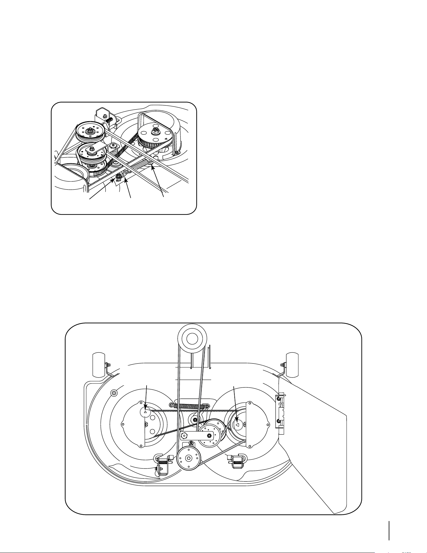
23sección 7— serviciO
necesario limpiar la parte inferior de la plataforma de corte
para acceder al tornillo hexagonal. Vea la Figura 7-4.
Haciendo fuerza sobre la polea intermedia de la correa
de sincronización o bien sobre el soporte intermedio de
la correa de sincronización, gire y sostenga el soporte
intermedio contra la tensión del resorte la distancia suficiente
para permitir la elevación de la correa de sincronización
hacia afuera y arriba de la polea intermedia. Suelte el soporte
intermedio con cuidado. Vea la Figura 7-4.
Figura 7-4
Enlace la correa de sincronización y levántela hacia afuera
de la polea de sincronización y por encima del conjunto del
husillo ubicado a la derecha. Pase la correa entre la polea de
transmisión que está en la parte superior del conjunto del
husillo y la cubierta del husillo para sacarla.
Repita el procedimiento precedente para sacar la correa de la
polea de sincronización del conjunto del husillo que está a la
izquierda. Vea la Figura 7-4.
Enlace la nueva correa de sincronización y pásela entre
la polea de transmisión que está en la parte superior del
conjunto del husillo que está a la derecha y la cubierta del
•
•
•
•
husillo. Baje la correa hasta que quede floja alrededor de la
polea de sincronización derecha. Vea la Figura 7-4.
Tenga en cuenta las flechas que están en la parte superior de
la polea de sincronización del husillo izquierdo y en la polea
de transmisión del conjunto del husillo que está a la derecha.
Estas flechas de sincronización DEBEN ubicarse a 90° una de
otra como se indica en la Figura 7-5.
Rote el conjunto del husillo que está a la derecha para
posicionar la flecha de sincronización de la polea de
transmisión como se indica en la Figura 7-5. Luego, sin
mover la polea de transmisión derecha, ajuste la correa de
transmisión contra la polea de sincronización derecha, por
encima de la polea intermedia de la correa de sincronización
y por encima de la polea de sincronización izquierda.
Gire la polea de sincronización izquierda de manera que
su flecha de sincronización quede a 90° de la flecha de
sincronización del conjunto del husillo de la derecha. Vea la
Figura 7-5.
Enlace la correa de sincronización por encima de la polea de
sincronización izquierda, comprobando al mismo tiempo
que no se cambie la posición de ninguna de las poleas.
Luego de comprobar que el resorte esté enganchado al
soporte intermedio y al tornillo, gire el soporte intermedio
/ polea intermedia de sincronización contra la tensión del
resorte sólo la distancia suficiente para que pueda bajar la
parte posterior de la correa de sincronización sobre la polea
intermedia. Vea la Figura 7-5.
Verifique nuevamente las flechas de sincronización de las
dos poleas. Si se han desplazado de la posición de 90º al
tensionar la correa de sincronización, gire la polea intermedia
para aliviar la tensión de la correa y reubique las poleas. Las
flechas de sincronización se DEBEN posicionar a 90° una
de otra como se indica en la Figura 7-5.
Coloque nuevamente los componentes del tope de
retención del soporte intermedio, como estaban instalados
originalmente en el alojamiento de la plataforma, y ubíquelo
•
•
•
•
•
•
•
Figura 7-5
Tope de retención
del soporte
Soporte intemedio
y polea intermedia
Resorte y
tornillo
Polea de sincronización
Flecha de
sincronización
Polea de transmisión
Flecha de
sincronización
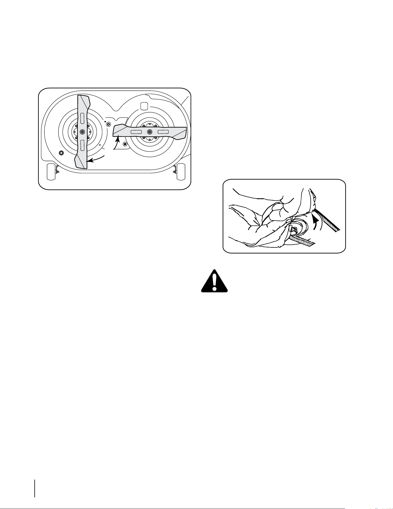
24 sección 7— serviciO
de manera que quede una separación de 1/8” entre el tope
de retención y el soporte intermedio. Ajuste el tornillo
hexagonal y la tuerca de seguridad con brida para sujetarlos
en la posición corregida.
Si la correa de sincronización estaba instalada correctamente
y las flechas de sincronización estaban ubicadas como se
indica en la Figura 7-5, las cuchillas de corte deben estar en la
posición que aparece en la Figura 7-6.
Figura 7-6
Instale nuevamente la correa de la potencia de arranque
en la polea de transmisión del husillo derecho e instale
nuevamente la plataforma según se indica en la sección
“Reinstalación de la plataforma de corte” a continuación.
Reinstalación de la plataforma de corte
Hay dos métodos para volver a instalar la plataforma de
corte en el tractor. Uno de los métodos implica rotar el
soporte intermedio de la potencia de arranque para aflojar
suficientemente la tensión de la correa para poder colocarla
ya sea en la polea de la potencia de arranque o en la polea
intermedia fija. Ya que ese método es difícil, recomendamos
usar el segundo método de hacer rodar la correa sobre la
polea de la potencia de arranque (PTO).
Instale la plataforma de corte de la siguiente manera:
Desde el lado derecho del tractor, deslice la plataforma
debajo del tractor alineando las ménsulas de suspensión
traseras de la plataforma con los brazos de elevación de la
plataforma.
Deslice la plataforma hacia adelante y coloque la varilla
de suspensión frontal de la plataforma en las ranuras de
la ménsula de suspensión frontal de la plataforma. Ahora
deslice la plataforma hacia atrás para que la varilla de
suspensión frontal quede delante de las ranuras.
Usando la palanca de elevación de la plataforma, baje los
brazos de elevación de la plataforma. Desde cualquiera
de los lados del tractor, tire hacia afuera el pasador de
la ménsula de suspensión posterior de la plataforma,
alineando el orificio del brazo de elevación de la
plataforma con el pasador de soporte de la plataforma
y suelte el pasador para que pase a través del brazo de
elevación de la plataforma. Repita este paso en el otro
lado del tractor para sujetar la plataforma.
Luego de asegurarse de que la correa de la plataforma
está correctamente engranada en todas las poleas de
la plataforma, pase la correa hacia adelante a través del
centro de la varilla de suspensión frontal de la plataforma
•
•
•
•
•
•
y hacia la polea de la potencia de arranque en la parte
inferior del motor.
Usando la manija de elevación de la plataforma, levante
la plataforma a la posición que le ofrece mayor recorrido
horizontal de la correa entre las poleas de la plataforma y
la polea de la potencia de arranque en la parte inferior del
motor.
Siéntese delante del tractor y, mirando hacia atrás,
asegúrese de que la correa no esté doblada; luego busque
debajo del tractor, tome la correa y tire la misma hacia la
polea de la potencia de arranque (PTO).
NOTA: En las siguientes instrucciones, las referencias a la
izquierda y la derecha son desde el frente del tractor.
Tire el lado derecho de la correa hacia adelante y coloque
el lado en V angosto de la correa en la polea de la potencia
de arranque (PTO).
Sosteniendo la correa y la polea juntas, rote la polea
hacia la izquierda. Siga sosteniendo y rotando la polea y
la correa hasta que la correa se enrolle totalmente en la
polea de la potencia de arranque (PTO). Vea la Figura 7-7.
Figura 7-7
ADVERTENCIA: Tenga cuidado de no pellizcarse
los dedos mientras enrolla la correa en la polea de
la potencia de arranque.
Control de la sincronización de las cuchillas de corte
Durante el funcionamiento normal la sincronización de las
cuchillas de corte se puede alterar por la presencia de cargas
anormales en una o ambas cuchillas de corte. Verifique
regularmente las flechas de sincronización de los conjuntos
de husillo para comprobar que estén a 90° una de otra.
Si las flechas de sincronización no están a 90° una de otra,
proceda de la siguiente manera:
Saque la plataforma del tractor. Saque el tope de
retención del soporte intermedio. Vea la Figura 7-4.
Gire el soporte intermedio/ la polea intermedia para
aliviar la tensión de la correa de sincronización y reubique
la polea de transmisión y/ o la polea de sincronización
para lograr la orientación de 90º de las flechas de
sincronización.
Coloque nuevamente el tope de retención del soporte
intermedio de manera que quede una separación de 1/8”
entre el tope de retención y el soporte intermedio. Ajuste
el tornillo hexagonal y la tuerca de seguridad con brida
para sujetarlos en la posición corregida.
•
•
•
•
•
•
•
PTO Belt
Rotate
Pulley
Correa de
la potencia
de arranque
(PTO)
Rotar la
polea

Problema Causa Solución
El motor no arranca Perilla de potencia de arranque (PTO) (enganche
de cuchilla) conectada.
No está colocado el freno de mano.
Se ha desconectado el cable de las bujías.
La palanca de control del regulador no está en la
posición de arranque correcta.
No se ha activado el cebador
El depósito de combustible está vacío o el
combustible se ha echado a perder.
La línea del combustible está bloqueada.
Las bujías no funcionan correctamente.
Motor ahogado.
1.
2.
3.
4.
5.
6.
7.
8.
9.
Coloque la perilla en la posición de desconexión
(OFF).
Coloque el freno de mano.
Conecte el cable a las bujías.
Mueva la palanca del regulador a la posición FAST
(rápido).
Tire el control del CEBADOR hacia afuera.
Llene el depósito con gasolina limpia y nueva (de
menos de 30 días).
Limpie la línea de combustible y reemplace el filtro
de combustible.
Limpie o cambie las bujías o ajuste la separación.
Arranque el motor con el regulador en posición
FAST (rápido).
1.
2.
3.
4.
5.
6.
7.
8.
9.
El motor funciona de
manera errática
La unidad está funcionando con el CEBADOR
activado.
Se han aflojado los cables de la bujía.
La línea del combustible está tapada o el
combustible se ha echado a perder.
La ventilación en la tapa del combustible está
obstruida.
Agua o suciedad en el sistema del combustible.
El filtro de aire está sucio.
1.
2.
3.
4.
5.
6.
Presione el control del CEBADOR.
Conecte los cables de la bujía.
Limpie la línea de combustible; llene el tanque con
gasolina limpia y nueva y reemplace el filtro de
combustible.
Destape la ventilación o reemplace la tapa si está
dañada.
Vacíe el tanque de combustible. Llene el tanque con
gasolina limpia y nueva.
Reemplace el elemento de papel del filtro de aire o
limpie el depurador de espuma.
1.
2.
3.
4.
5.
6.
El motor recalienta El nivel de aceite del motor está bajo.
Flujo de aire restringido.
1.
2.
Llene el cárter con la adecuada cantidad y peso de
aceite.
Limpie los recortes de pasto y la suciedad
acumulados alrededor de las aletas de refrigeración
del motor y del alojamiento del soplador.
1.
2.
El motor vacila a altas
revoluciones
La separación de las bujías es muy pequeña. 1. Retire las bujías y reajuste la separación. 1.
El motor funciona con
dificultad en ralentí
Bujía atorada, averiada o exceso de separación.
El filtro de aire está sucio.
1.
2.
Reemplace las bujías. Configure la separación de la
bujía.
Reemplace el elemento del filtro de aire y/o limpie el
depurador.
1.
2.
Demasiada vibración Cuchilla de corte floja o descentrada.
Cuchilla dañada o curvada.
1.
2.
Apriete la cuchilla y el husillo.
Reemplace la cuchilla.
1.
2.
La cortadora de
césped no regresa
el recorte de césped
como abono
La velocidad del motor es demasiado lenta.
Césped húmedo.
Césped demasiado alto.
La cuchilla de la cortadora no está afilada.
1.
2.
3.
4.
Coloque el control del regulador en la posición FAST
(velocidad rápida, representada por una liebre).
No realice abono cuando el césped está húmedo.
Corte una vez a una altura de corte elevada y luego
vuelva a cortar el césped a la altura deseada, o haga
una pasada de corte más angosta.
Afile o cambie la cuchilla.
1.
2.
3.
4.
Corte desigual La plataforma no está correctamente nivelada.
La cuchilla de la cortadora no está afilada.
Presión de neumáticos desigual.
1.
2.
3.
Realice un ajuste de la plataforma lado a lado.
Afile o cambie la cuchilla.
Verifique la presión de los cuatro neumáticos.
1.
2.
3.
Solución de Problemas
8
25

Piezas de reemplazo
9
26
Póngase en contacto con su distribuidor de Cub Cadet para solicitar piezas de reemplazo. Si usted no tiene un distribuidor, llame a
la Línea de Asistencia al Cliente de Distribuidores en el 1-877-282-8684 o visite www.cubcadet.com para encontrar el distribuidor de
Cub Cadet más cercano en su área. Llame por teléfono al (800) 965-4CUB para solicitar piezas de reemplazo o un Manual de Piezas
de Repuesto completo (tenga el número de modelo y número de serie de su tractor a mano). En www.cubcadet.com también podrá
descargar el Manual de Piezas de Repuesto sin cargo alguno.
Cambio de la correa de sincronización Modelo i1042
Correa de transmisión inferior - póngase en contacto con el distribuidor 954-04134
Correa de motor a plataforma / arranque de potencia (PTO) 954-04185
Correa de sincronización de la plataforma 954-04167
Cuchillas 942-04217 (Cantidad 2)
Husillo de plataforma - Derecho 618-04512
Husillo de plataforma - Izquierdo 618-04516
Ruedas esféricas delanteras de la plataforma 734-04155 (Cantidad 2)
Batería 925-1707D
Solenoide de arranque 725-04439
Llaves de encendido 725-2054A
Filtro de aceite del motor KH-52-050-02
Aceite del motor (capacidad 57,6 onzas) 737-3030A (1ct.)
Elemento del filtro de aire KH-32-083-03-S
Elemento depurador de espuma del filtro de aire del motor KH-32-083-05-S
Filtro de combustible KH-25-050-22-S
Bujía de encendido 759-3336
Conjunto de canal de descarga de la plataforma 631-04254
MODELO DESCRIPCIÓN
19A70001000 Colector de césped con sistema de embolsado trasero doble para plataformas de 46”
19A70002000 Kit de abono
190-833-000 Cuchilla de 46” para oruga
19A-102-100 Carro de acero de 18 pies cúbicos
19A-106-100 Carro Poly de 10 pies cúbicos
19A-105-100 48” Distribuidor al voleo
19A-103-100 42” Aspiradora
19A-104-100 Rociador de 25 galones
19A-107-100 48” Rasqueta
19A-113-100 48” Rodillo Poly
19A-108-100 48” Aireador de clavija
19A-109-100 48” Aireador de espiga
Aditamentos y accesorios
10

DECLARACIÓN DE GARANTÍA DE CONTROL DE EMISIONES DE CALIFORNIA
DERECHOS Y OBLIGACIONES DE SU GARANTÍA
El Departamento de los Recursos de Aire de California y MTD Consumer Group Inc, se complacen en explicar la garantía del sistema de control de emisiones por
evaporación de su cortadora de césped 2008. En California, las nuevas máquinas para cortar césped se deben diseñar, construir y equipar de modo de cumplir
con las rigurosas normas contra la polución del estado. MTD Consumer Group Inc debe garantizar el sistema de control de emisiones por evaporación (EECS)
de su cortadora de césped por el período de tiempo indicado más abajo, siempre y cuando no exista uso incorrecto, negligencia o mantenimiento inadecuado de
dicha máquina.
El sistema EECS puede incluir piezas tales como el carburador, el sistema de inyección de combustible, el sistema de encendido, el convertidor catalítico,
los depósitos de combustible, las líneas de combustible, los tapones de combustible, las válvulas, contenedores, filtros, mangueras de vapor, abrazaderas,
conectores y otros componentes afines relacionados con las emisiones.
Donde exista una condición cubierta por la garantía, MTD Consumer Group Inc. reparará su cortadora de césped sin costo alguno incluyendo el
diagnóstico, las piezas y la mano de obra.
COBERTURA DE LA GARANTÍA DEL FABRICANTE:
Este sistema de control de emisiones por evaporación se garantiza por el término de dos años. Si alguna parte de su equipo relacionada con las emisiones por
evaporación es defectuosa, MTD Consumer Group Inc. reparará o sustituirá dicha parte.
RESPONSABILIDADES DEL PROPIETARIO SEGÚN LA GARANTÍA:
En su carácter de propietario de la cortadora de césped, usted es responsable del mantenimiento requerido que se especifica en el manual del propietario. MTD
Consumer Group Inc le recomienda que conserve todos los recibos que cubren el mantenimiento de su cortadora de césped, no obstante lo cual MTD Consumer
Group Inc no podrá denegar el cumplimiento de la garantía únicamente por la falta de los recibos.
Como propietario de la cortadora de césped, usted debe saber que MTD Consumer Group Inc. puede denegar la cobertura de la garantía si su cortadora de
césped o una pieza de la misma fallan debido a uso incorrecto, negligencia, mantenimiento indebido o a modificaciones no aprobadas.
usted es responsable de presentar la cortadora de césped al centro de distribución o de mantenimiento de MTD Consumer Group Inc. tan pronto como aparezca
el problema. las reparaciones cubiertas por la garantía se deben llevar a cabo en un lapso razonable que no exceda de 30 días. Si tiene alguna pregunta
respecto de la cobertura de la garantía, póngase en contacto con el Departamento de Mantenimiento de MTD Consumer Group Inc. al teléfono 1-800-800-7310.
COBERTURA DE LA GARANTÍA DE EMISIONES GENERALES:
MTD Consumer Group Inc garantiza al comprador final y a cada comprador subsiguiente que la cortadora de césped: está diseñada, construida y equipada de
modo de cumplir con todas las regulaciones aplicables y que se encuentra libre de defectos de materiales y de fabricación que pudieren causar la falla de una
pieza garantizada idéntica, en todos los aspectos materiales, a la pieza descripta en la solicitud de certificación de MTD Consumer Group Inc.
El período de garantía comienza en la fecha de entrega de la cortadora al comprador final o en la fecha en que la máquina se pone en funcionamiento por primera
vez. El período de garantía es de dos años.
Sujeto a ciertas condiciones y exclusiones que se indican a continuación, la garantía de las piezas relacionadas con las emisiones es la siguiente:
1. Cualquier pieza garantizada que no esté programada para ser reemplazada como parte del mantenimiento requerido en las instrucciones escritas
suministradas se garantiza por el período de garantía arriba mencionado. Si la pieza falla durante el período de cobertura de la garantía, la misma será
reparada o reemplazada por MTD Consumer Group Inc. de acuerdo con el párrafo (4) a continuación. Cualquier pieza reparada o reemplazada según la
garantía se garantizará por el resto del período de garantía.
2. Cualquier pieza garantizada que esté programada solamente para inspección regular en las instrucciones escritas suministradas se garantiza por el período
de garantía arriba mencionado. Cualquier pieza reparada o reemplazada según la garantía se garantizará por el resto del período.
3. Cualquier pieza garantizada que esté programada para reemplazo según el mantenimiento requerido de conformidad con las instrucciones escritas
suministradas, se garantiza por el período de tiempo anterior a la primera fecha de reemplazo programada para esa pieza. Si la pieza falla antes del primer
reemplazo programado, la misma será reparada o reemplazada por MTD Consumer Group Inc. de acuerdo con el párrafo (4) a continuación. Cualquier pieza
reparada o reemplazada bajo garantía se garantizará por el resto del período anterior al primer reemplazo programado puntual para esa pieza.
4. la reparación o el reemplazo de cualquier parte garantizada de conformidad con las disposiciones de la garantía que aquí se estipula se debe realizar en un
centro de garantía sin costo alguno para el propietario.
5. No obstante las disposiciones que aquí se estipulan, los servicios o reparaciones bajo garantía se suministrarán en todos nuestros centros de distribución bajo
franquicia de mantenimiento para los motores o equipo en cuestión.
6. El propietario de la cortadora de césped no deberá pagar el trabajo de diagnóstico directamente asociado con una pieza garantizada defectuosa en relación
con las emisiones, siempre y cuando dicho trabajo de diagnóstico se realice en un centro de garantía.
7. MTD Consumer Group Inc es responsable por daños causados a otros componentes de motores o equipo derivados de la falla bajo garantía de cualquier
pieza garantizada.
8. Durante la totalidad del período de garantía arriba mencionado, MTD Consumer Group Inc mantendrá un suministro de piezas bajo garantía suficiente para
satisfacer la demanda esperada de tales piezas.
9. Cualquier pieza de reemplazo se podrá usar para el cumplimiento del mantenimiento o las reparaciones bajo garantía y se suministrarán sin cargo para el
propietario. Dicho uso no reducirá las obligaciones de garantía de MTD Consumer Group Inc.
10. No se podrán usar piezas adicionales ni modificadas que no estén exentas de acuerdo con el Consejo de Recursos Aéreos (Air Resources Board). El uso de
cualquier pieza adicional o modificada no exenta por el comprador final será causal de invalidez de los reclamos bajo garantía. MTD Consumer Group Inc no
tendrá responsabilidad por la garantía de fallas de piezas garantizadas que fueren causadas por el uso de una pieza no exenta adicional o modificada.
PIEZAS GARANTIZADAS:
la reparación o el reemplazo de cualquier pieza garantizada que de otro modo pudiese estar cubierta por la garantía podrá ser excluida de tal cobertura de
garantía si MTD Consumer Group Inc demuestra que la cortadora de césped es objeto de uso incorrecto, negligencia o mantenimiento inadecuado, y que tal
uso incorrecto, negligencia o mantenimiento inadecuado fue causa directa de la necesidad de reparación o reemplazo de dicha pieza. No obstante lo antedicho,
cualquier ajuste de un componente con un dispositivo de limitación de ajuste instalado en fábrica y que funcione adecuadamente, podrá ser cubierto por la
garantía. la siguiente lista de piezas es cubierta por la garantía de emisiones: línea de combustible, abrazaderas de la línea de combustible

IMPORTANTE: Para obtener cobertura de garantía, el propietario
debe presentar una evidencia original de la compra y los registros
de mantenimiento correspondientes al centro de servicio técnico
autorizado del distribuidor. Consulte el manual del operador para
obtener información sobre los intervalos de mantenimiento y servicio
requeridos.
La siguiente garantía limitada es otorgada por Cub Cadet LLC con
respecto a nuevos productos adquiridos o arrendados y utilizados en
Estados Unidosy/o sus territorios y posesiones, y por MTD Products
Limited con respecto a nuevos productos adquiridos o arrendados y
utilizados en Canadá y/o sus territorios y posesiones (cualquiera de las
dos entidades, respectivamente, “Cub Cadet”).
Cub Cadet garantiza este producto (excluyendo las piezas de desgaste
normal, baterías, bastidor, eje frontal y accesorios según se describe a
continuación) contra defectos en los materiales y mano de obra por un
período de tres (3) años o ciento veinte (120) horas de operación, lo
que suceda primero, a partir de la fecha de compra minorista original o
arrendamiento y, a su opción, reparará o reemplazará, sin costo alguno,
cualquier pieza que presente defectos en los materiales o mano de obra.
Se garantiza que las piezas con desgaste normal están libres de defectos
en los materiales y mano de obra por un período de treinta (30) días
a partir de la fecha original de compra o arrendamiento. Las piezas
sujetas a desgaste normal incluyen pero no se limitan a: correas,
cuchillas, adaptadores de cuchilla, bolsas recolectoras de pasto, ruedas
de plataforma, asientos y neumáticos.
Las baterías tienen una garantía limitada prorrateada de un año contra
defectos en los materiales y mano de obra, con 100% de reemplazo
durante los tres primeros meses. Después de los tres meses, el
crédito por reemplazo de batería se basará en los meses remanentes
del período de doce (12) meses desde la fecha original de compra o
arrendamiento. Todo reemplazo de batería será garantizado únicamente
por el plazo restante del período original de la garantía.
Bastidor y eje frontal - Cub Cadet garantiza el bastidor, y eje de pivote de
hierro fundido frontal contra defectos en los materiales y mano de obra
por un período de cinco (5) años o 500 horas, lo que suceda primero, a
partir de la fecha original de compra o arrendamiento.
Accesorios - Cub Cadet garantiza que los accesorios de este producto
están libres de defectos de material y mano de obra durante un período
de un (2) año a partir de la fecha de compra o arrendamiento original del
accesorio. Los accesorios incluyen, pero no se limitan a: colectores de
césped y kits para abono.
Esta garantía limitada sólo se aplicará si el producto ha sido operado
y mantenido de acuerdo con las instrucciones del Manual del
Operador que se proporciona con el producto y no ha sido sujeto a uso
inapropiado, abuso, uso comercial, abandono, accidente, mantenimiento
incorrecto, alteración, vandalismo, robo, incendio, inundación o algún
daño debido a otro peligro o desastre natural. El daño resultante
de la instalación o el uso de piezas, accesorios o complementos no
aprobados por Cub Cadet para su uso con el o los productos incluidos
en este manual anulará la garantía en lo que respecta a esos daños.
Además, Cub Cadet puede rechazar la cobertura de la garantía si el
medidor horario o cualquier parte del mismo, es alterado, modificado,
desconectado o de alguna otra forma forzado.
CÓMO SOLICITAR Y OBTENER SERVICIO TÉCNICO: El servicio de la
garantía está disponible, CON PRUEBA DE COMPRA Y REGISTROS DE
MANTENIMIENTO CORRESPONDIENTES a través de su distribuidor
local autorizado para el mantenimiento. Para localizar al distribuidor de
su zona:
En Estados Unidos de América:
Consulte sus páginas amarillas, o póngase en contacto con Cub Cadet
LLC en P.O. Box 361131, Cleveland, Ohio 44136-0019, llame al 1-877-
282- 8684, o visite nuestro sitio web en www.cubcadet.com.
En Canadá:
Contacte MTD Products Limited, Kitchener, ON N2G 4J1, llame al 1-
800-668-1238 o visite nuestro sitio web en www.mtdcanada.com.
Sin limitación de lo anteriormente dicho, esta garantía limitada no ofrece
cobertura en los siguientes casos:
a. Los artículos necesarios para el mantenimiento de rutina como por
ejemplo lubricantes, filtros, afiladores de cuchillas, sincronización
del motor, los ajustes de los frenos, del embrague o de la plataforma
y el deterioro normal del acabado exterior debido al uso o
exposición.
b. Mantenimiento no realizado por el distribuidor de servicio autorizado.
c. Cub Cadet no extiende ninguna garantía para los productos vendidos
o exportados fuera de los Estados Unidos de América y/o Canadá,
y sus respectivas posesiones y territorios, excepto para aquellos
vendidos a través de los canales autorizados de distribución de
exportaciones de Cub Cadet.
d. Piezas de reemplazo y\o accesorios que no son piezas originales de
Cub Cadet.
e. Gastos de transporte y visitas técnicas.
No existen garantías implícitas, incluyendo sin limitación cualquier
garantía implícita de comerciabilidad o adaptabilidad para un
propósito en particular. No se aplicará ninguna garantía después
del período aplicable de la garantía expresa por escrito según
lo indicado más arriba. Ninguna otra garantía expresa más allá
de las mencionadas anteriormente, extendida por personas o
personas jurídicas, incluidos los distribuidores o los minoristas,
con respecto a los productos, obligará a Cub Cadet. El recurso
exclusivo es reparar o reemplazar el producto según lo anteriormente
establecido. Los términos de esta garantía cubren las reparación
únicas y exclusivas que surgen de la venta y/o arrendamiento de los
productos cubiertos por la presente. Cub Cadet no será responsable
de las pérdidas o los daños incidentales o resultantes, incluyendo sin
limitación, los gastos incurridos para los servicios de mantenimiento
del pasto, o los gastos de arrendamiento para reemplazar de manera
transitoria un producto bajo garantía.
Algunas jurisdicciones no permiten la exclusión o limitación de los
daños y perjuicios incidentales o resultantes, o las limitaciones sobre
la duración de las garantías implícitas, por lo que las exclusiones o
limitaciones mencionadas anteriormente pueden no serle de aplicación.
En ningún caso se obtendrá una compensación mayor al monto
del precio de compra del producto vendido. La modificación de las
características de seguridad del producto anulará esta garantía. Usted
asume el riesgo y la responsabilidad de las pérdidas, daños o lesiones
que sufran usted y sus bienes y / u otras personas y sus bienes como
resultado del uso incorrecto o de la falta de capacidad para usar este
producto.
Esta garantía limitada alcanza solamente al comprador original, o a la
persona que recibió el producto de regalo.
CÓMO SE RELACIONA LA LEGISLACIÓN LOCAL CON ESTA GARANTÍA:
Esta garantía limitada le otorga derechos legales específicos y usted
también puede tener otros derechos que varían de una jurisdicción a
otra.
GARANTÍA LIMITADA DEL FABRICANTE
CUB CADET LLC PARA TRACTORES
DE SERIE 1000 Y SERIE 1500
Cub Cadet LLC, P.O. BOX 361131 CLEVELAND, OHIO 44136-0019; Teléfono: 1-877-282-8684
MTD Products Limited, Kitchener, ON N2G 4J1, teléfono: 1-800-668-1238
GDOC-100014 REV. B