G500H Flight Display System
Instructions for Continued Airworthiness
Bell 206A/B Series
Reg. No.____________ S/N_______________
STC SR02295LA
Dwg. Number:
190-01150-11 Rev. 5
Garmin International, Inc.
1200 E. 151st Street
Olathe, Kansas 66062 USA
Record of Revision
Rev.
Date
Description of Change
1
02/11/10
Initial Release
2
04/12/10
Update to latest installation data revisions; changed VFR placard text;
updated equipment station locations.
3
11/24/15
Update to latest installation data revisions; added “G500H GDL 88H
Harness Assembly”.
4
11/25/16
Update to Table 2-2 GDU 620 Alert Troubleshooting Guide; update
reference documents in Section 2.1; remove LRU location diagram in
Section 2.2; add rotorcraft specific LRU location and wire routing diagram
(Section 2.8); move circuit breaker diagram to Section 2.8.
5
02/11/2020
Update to include GSU 75H, GRS 79H, and GDC 72H

G500H Flight Display System 190-01150-11 Rev. 5
Instructions for Continued Airworthiness Bell 206A/B Series Page ii
TABLE OF CONTENTS
1 INTRODUCTION ................................................................................................................... 1
1.1 Purpose ................................................................................................................. 1
1.2 Scope .................................................................................................................... 1
1.3 Document Control ................................................................................................. 1
1.4 Permission to Use Certain Documents ................................................................. 1
1.5 Definitions ............................................................................................................. 1
2 INSTRUCTIONS FOR CONTINUED AIRWORTHINESS .................................................... 2
2.1 Introduction ........................................................................................................... 2
2.2 Description of Alteration ........................................................................................ 2
2.3 Control, Operating Information ............................................................................. 4
2.4 Servicing Information ............................................................................................ 4
2.5 Periodic Maintenance Instructions ........................................................................ 5
2.6 Troubleshooting Information ................................................................................. 8
2.7 Removal and Installation Information ................................................................... 18
2.8 Diagrams............................................................................................................... 29
2.9 Special Inspection Requirements ......................................................................... 31
2.10 Application of Protective Treatments .................................................................... 31
2.11 Special Tools ........................................................................................................ 31
2.12 Additional Instructions ........................................................................................... 31
2.13 Overhaul Period .................................................................................................... 31
2.14 ICA Revision and Distribution ............................................................................... 31
2.15 Assistance............................................................................................................. 32
2.16 Implementation and Record Keeping ................................................................... 32
3 AIRWORTHINESS LIMITATIONS ........................................................................................ 33

G500H Flight Display System 190-01150-11 Rev. 5
Instructions for Continued Airworthiness Bell 206A/B Series Page 1 of 33
1 INTRODUCTION
1.1 Purpose
This document is designed for use by the installing agency of the Garmin G500H PFD/MFD System as
Instructions for Continued Airworthiness in response to Title 14 CFR Part 27.1529, Part 27 Appendix A.
This ICA includes information required by the operator to adequately maintain the Garmin G500H
system installed under STC SR02295LA.
1.2 Scope
This document provides Instructions for Continued Airworthiness (ICA) for the G500H PFD/MFD system
as installed under STC SR02295LA.
1.3 Document Control
This document shall be released, archived, and controlled in accordance with the Garmin document
control system. When this document is revised, refer to Section 2.14 for information on how to gain FAA
acceptance or approval and how to notify customers of changes.
1.4 Permission to Use Certain Documents
Permission is granted to any corporation or person applying for approval of a Garmin G500H system to
use and reference appropriate STC documents to accomplish the Instructions for Continued
Airworthiness and show compliance with STC engineering data. This permission does not construe
suitability of the documents. It is the responsibility of the applicant to determine the suitability of the
documents for the ICA.
1.5 Definitions
The following terminology is used within this document:
1) ACO: Aircraft Certification Office
2) ADC: Air Data Computer
3) AEG: Aircraft Evaluation Group
4) AHRS: Attitude Heading Reference System
5) ADAHRS: Air Data and Attitude Heading Reference System
6) CFR: Code of Federal Regulations
7) FAA: Federal Aviation Administration
8) ICA: Instructions for Continued Airworthiness
9) MFD: Multi-Function Display
10) PFD: Primary Flight Display
11) PMI: Principle Maintenance Inspector
12) STC: Supplemental Type Certificate

G500H Flight Display System 190-01150-11 Rev. 5
Instructions for Continued Airworthiness Bell 206A/B Series Page 2 of 33
2 INSTRUCTIONS FOR CONTINUED AIRWORTHINESS
2.1 Introduction
Content, Scope, Purpose and
Arrangement:
This document identifies the Instructions for Continued
Airworthiness for the modification of the rotorcraft by installation
of the Garmin G500H PFD/MFD System.
Applicability:
Applies to Bell models 206A, 206A-1 and 206B rotorcraft altered
by installation of the Garmin G500H PFD/MFD System.
Definition of Abbreviations:
See Section 1.5
Precautions:
None
Units of measurement:
None
Referenced publications:
Garmin 190-01150-06 Rev. 5 “G500H Rotorcraft STC
Installation Manual” or later FAA Approved Revisions
Garmin 190-01150-02 Rev. C “G500H PILOT GUIDE” or later
revision
Garmin 190-01150-07 “Installation Manual Addendum G500H
Part 27 AML STC”
Bell BHT-ALL-SPM “Bell Standard Practices Manual”
Retention:
This document, or the information contained within, will be
included in the rotorcraft’s permanent records.
2.2 Description of Alteration
This STC upgrades existing avionics for the Bell 206A/B rotorcraft as summarized below.
The Garmin G500H Flight Display System consists of an instrument panel mounted GDU 620 display
and remote mounted LRUs which provide data to the display. The GDU 620 provides controls for the
G500H system and a PFD and MFD in the pilot’s primary field of view. The remote mounted LRUs
include one GRS 77H/79H AHRS, one GMU 44 Magnetometer, one GDC 72H/74H ADC, and one GTP
59 OAT probe. Alternately, one GSU 75H ADAHRS can be installed in place of GRS and GDC unit
combination.
Rotorcraft modified under this G500H STC are restricted to VFR only, including rotorcraft that may not
have previously been restricted to VFR. To clarify this operation limitation, a placard with the text,
“APPROVED FOR DAY/NIGHT VFR” is required to be in the pilot’s view.
All installed G500H equipment is connected to a power bus that receives power as soon as the battery
master switch is turned on.
Separate circuit breakers have been installed in the overhead circuit breaker panel for each for the GDU
620 (PFD), GRS 77H/79H + GMU 44 (AHRS), and GDC 72H/74H (ADC) (as shown in the diagram in
Section 2.8). If a GSU 75H is installed in lieu of federated GRS/GDC units, it will have a single circuit
breaker labeled ADAHRS.
G500H Flight Display System 190-01150-11 Rev. 5
Instructions for Continued Airworthiness Bell 206A/B Series Page 3 of 33
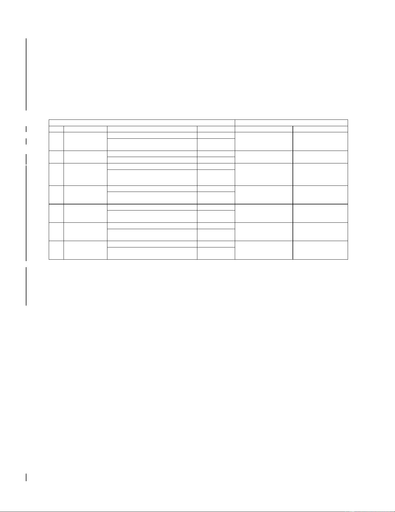
2.2.1 Weight and Balance Information
Weight and balance computation is required after the installation is complete. Follow the applicable
procedures established in Bell 206A/B Series Maintenance Manual BHT-206A/B-SERIES-MM-2,
Chapter 8, Weight and Balance. Make applicable entries in the equipment list indicating items added,
removed, or relocated along with the date the installation was accomplished.
G500H equipment weights and moment arms are provided below. Refer to section 2.2.2 for a sample
calculation. Include a copy of the updated aircraft weight and balance in the aircraft POH/AFM
Weight and Balance Bell 206 A/B
MOMENT ARM (IN)
ITEM
PART NUMBER
EQUIPMENT
WEIGHT (LB)
LONGITUDINAL
LATERAL
1
011-01264-50
OR
011-01264-60
GDU 620 (Unit Only)
6.38
38.6
6.3
GDU 620 (Installed with rack and
connector)
7.04
2
011-00882-11
GDC 74H (Unit Only)
1.70
32.8
0.0
GDC 74H (Installed with connector)
1.92
3
011-00868-20
GRS 77H (Unit Only)
2.80
151.4 (Primary)
OR
60.4 (Secondary)
-10.3 (Primary)
OR
-18.6 (Secondary)
GRS 77H (Installed with rack and
connector)
3.46
4
011-00870-10
GMU 44 (Unit Only)
0.35
196.3 (Primary)
OR
217.5 (Secondary)
0.0 (Primary &
Secondary)
GMU 44 (Installed with rack and
connector)
0.50
5
011-03734-20
GDC 72H (Unit Only)
1.26
32.8
0.0
GDC 72H (Installed with rack and
connector)
1.71
6
011-03732-20
GRS 79H (Unit Only)
1.08
151.4 (Primary)
OR
60.4 (Secondary)
-10.3 (Primary)
OR
-18.6 (Secondary)
GRS 79H (Installed with rack and
connector)
1.45
7
011-03094-20
GSU 75H (Unit Only)
1.36
32.8
0.0
GSU 75H (Installed with rack and
connector)
1.72
[1] The longitudinal arm is measured in terms of the fuselage station (FS) number.
[2] The lateral arm is measured in terms of the butt line (BL). The centerline of the helicopter is BL0.00.
The moment arms to the left side (looking forward) are negative (-) and the moment arms to the right
side are positive (+).
G500H Flight Display System 190-01150-11 Rev. 5
Instructions for Continued Airworthiness Bell 206A/B Series Page 4 of 33
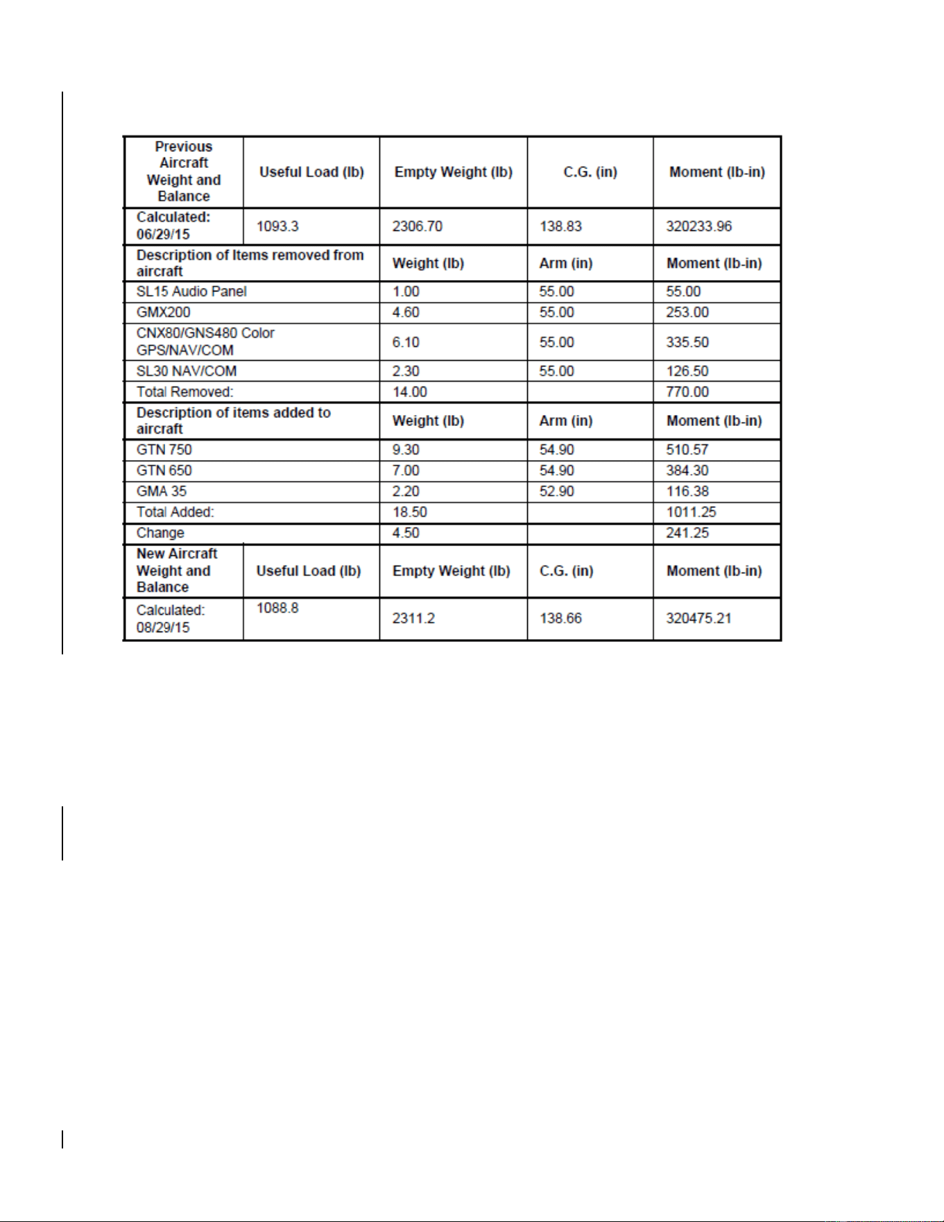
2.2.2 Weight and Balance Calculation Sample
2.3 Control, Operating Information
See the G500H Pilot’s Guide or the G500H STC Installation Manual, listed under the reference
documentation in paragraph 2.1 of this document, for system operation and self-test information.
2.4 Servicing Information
None. In the event of system failure, troubleshoot the G500H system in accordance with Section 2.6
Troubleshooting Information.

G500H Flight Display System 190-01150-11 Rev. 5
Instructions for Continued Airworthiness Bell 206A/B Series Page 5 of 33
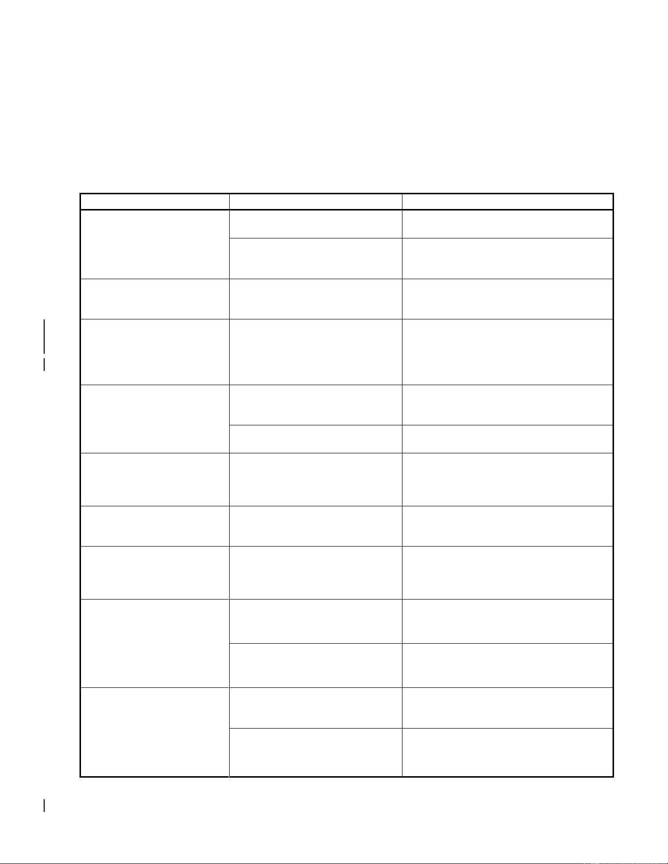
2.5 Periodic Maintenance Instructions
Maintenance of the components installed by this STC is on condition, except as noted in the following
table.
Item
Interval
Description/Procedure
GRS 77H/79H AHRS
GSU 75H ADAHRS
5 years
The GRS 77H/79H and GSU 75H utilize an Earth magnetic field
model which is updated once every five years as part of the
Aviation Database maintained by the owner/operator. If the
magnetic model is not current, the unit will issue an alert upon
startup indicating the model has expired. The model can be
updated by inserting an aviation database card with an updated
IGRF model and powering on the system. A prompt will direct the
user to press ENT to update the model.
GDC 72H/74H ADC
GSU 75H ADAHRS
On condition
Per Part 43 Appendix E, paragraph (b)(2), the GDC 72H/74H and
GSU 75H must be checked using a test procedure equivalent to
Part 43 Appendix E, paragraph (b)(1) with the following exception:
The tests of sub-paragraphs (iv) (Friction) and (vi) (Barometric
Scale Error) are not applicable because the digital outputs of the
GDC 72H/74H and GSU 75H are not susceptible to these types
of errors.
GDU 620
GRS 77H/79H
GDC 72H/74H
GSU 75H
GMU 44
GTP 59
12 Calendar
Months
Conduct a visual inspection (look for signs of wear, deterioration,
or damage to wires, backshells, or connectors) on units and their
wire harnesses to ensure installation integrity:
1. Gain access to LRU (see Section 2.8 for LRU locations)
2. Inspect each unit for security of attachment.
3. Inspect all knobs and buttons for legibility.
4. Inspect condition of wiring, routing and attachment/clamping.
5. Inspect integrity of shield terminations.
6. Inspect for signs of corrosion on equipment and their rack
installations.

G500H Flight Display System 190-01150-11 Rev. 5
Instructions for Continued Airworthiness Bell 206A/B Series Page 6 of 33
Item
Interval
Description/Procedure
GDU 620
GRS 77H/79H
GDC 74H/72H
GSU 75H
GMU 44
GTP 59
Every 2000
flight hours or
ten (10)
years,
whichever is
first
Perform an electrical bonding test for each listed LRU:
1. Gain access to the LRU (see Section 2.8 for LRU location)
2. Disconnect all harness connectors from the LRU
3. Measure the resistance between the LRU and a nearby
exposed portion of aircraft metallic structure.
a. For the GDU 620, verify the resistance is less than or equal
to 40 milliohms. If the resistance is greater than 40
milliohms, refer to Section 3.5 of the Installation Manual
(190-01150-06) for the bonding preparation and maximum
resistance values that must be met.
b. For the GTP 59, verify the resistance is less than or equal
to 5 milliohms. If the resistance is greater than 5 milliohms,
refer to Section 3.5 of the Installation Manual (190-01150-
06) for the bonding preparation and maximum resistance
values that must be met.
c. For the GSU 75H, GRS 79H, and GDC 72H, verify the
resistance is less than or equal to 5 milliohms. If the
resistance is greater than 5 milliohms, refer to Section 4.2
of the Installation Manual Addendum (190-01150-07) for the
bonding preparation and the maximum resistance values
that must be met.
d. For the remaining LRUs, verify the resistance is less than or
equal to 20 milliohms. If the resistance is greater than 20
milliohms, refer to Section 3.5 of the Installation Manual
(190-01150-06) for the bonding preparation and maximum
resistance values that must be met.
4. Reconnect all disconnected harness connectors and ensure
they are secure
Repeat for each listed LRU.
GDU 620
On Condition
Over time, the display backlight lamp may dim and the display
may not perform as well in direct sunlight conditions. The user
must determine by observation when the display brightness is not
suitable for its intended use. Contact a Garmin factory repair
station when the backlight lamp requires service.
GDU 620
On Condition
Over time, the GDU cooling fans may degrade in performance
and need to be replaced in order to continue adequately cooling
the display system.
The cooling fan replacement procedure is contained in Section
2.7.2.
GTP 59
GMU 44
After a
suspected or
actual
lightning
strike
Conduct an inspection of the G500H system in accordance with
Section 2.9.1.

G500H Flight Display System 190-01150-11 Rev. 5
Instructions for Continued Airworthiness Bell 206A/B Series Page 7 of 33
Item
Interval
Description/Procedure
GDU 620
GRS 77H/79H
GDC 72H/74H
GSU 75H
GMU 44
GTP 59
On Condition
Removal and replacement of the G500 system LRUs can be
accomplished by referring to Section 2.7 for instructions.
G500H Flight Display System 190-01150-11 Rev. 5
Instructions for Continued Airworthiness Bell 206A/B Series Page 8 of 33
2.6 Troubleshooting Information
If error indications are displayed on the GDU 620 display unit, consult the Troubleshooting section
contained below:
2.6.1 G500H Troubleshooting
Table 2-1. GDU 620 Troubleshooting Guide
Problem
Cause
Solution
Unit does not power up –
blank screen.
Improper wiring; circuit breaker
open.
Ensure power is properly wired to the
GDU 620 and the circuit breaker is closed.
Unit intensity turned down.
Ensure that unit is not in manual intensity
control mode with the intensity turned
down.
All expected configuration
pages are not displayed.
An Installer Unlock Card is not
inserted into the GDU 620.
Insert the Installer Unlock Card
P/N 010-00769-60 into the bottom slot of
the GDU 620 and cycle power.
The GDC or GSU OAT probe
type shows up as
UNKNOWN
The RS-232 connection to the
GDC 72H/74H or GSU 75H is not
working.
Ensure that the GDC 72H/74H or GSU
75H RS-232 connection to the GDU is
properly wired, and ensure that the GDC
72H/74H or GSU 75H circuit breaker is
closed.
When loading software, the
LRU software is not being
displayed on the
SOFTWARE UPLOAD page.
The software loader card is
installed in the bottom slot of the
GDU 620.
Insert the loader card in the top slot and
cycle power to the GDU.
The software loader card contains
no information.
Repeat the process for making the
software loader card.
Configuration errors are
displayed on power-up,
before the GDU enters
normal mode.
The configuration module has not
been updated.
Update the configuration module.
Vertical GPS deviation is not
displayed on the GDU 620.
For 400W/500W Series units, the
ARINC 429 vertical deviation
labels are not being transmitted.
Enable Labels on the 400W/500W Series
unit ARINC 429 configuration page.
Unable to control the GPS
course when in OBS mode.
The GPS navigator is not correctly
configures as LNAV1/2 or
SYS1/2.
Configure the ARINC 429 inputs/outputs
for LNAV1 (SYS1) or LNAV2 (SYS2)
based upon whether the navigator is
GPS1 or GPS2.
Data is not being received
from an ARINC 429 device.
(valid data is being received
on the 429 input port as
shown on the GDU 620
PORT MONITORING page)
ARINC 429 bus hi and low are
swapped.
Verify wiring.
Wrong device is connected to port
on GDU 620.
Use correct ports (refer to interconnect
details in Appendix D of the installation
manual).
Data is not being received
from an ARINC 429 device.
(no data is being received on
the 429 input port as shown
on the GDU 620 PORT
MONITORING page)
On the transmitting LRU, the
ARINC 429 transmitter speed is
not set correctly.
Set the ARINC 429 transmitter speed to
correct speed.
Wiring is not correct.
Check for continuity/shorts and correct as
required.

G500H Flight Display System 190-01150-11 Rev. 5
Instructions for Continued Airworthiness Bell 206A/B Series Page 9 of 33
Problem
Cause
Solution
Attitude and heading on
GDU 620 red ‘X’ / GRS
77H/79H or GSU 75H resets
during air data ground
testing.
Attitude and heading errors/resets
are possible if the air data tests
are conducted indoors without a
good GPS signal. With marginal
or no GPS signals present,
sudden changes in airspeed
caused by using a pressure tester
may result in attitude and heading
errors and possibly cause the
GRS 77H/79H or GSU 75H to
reset. This occurs because the
artificial changes in airspeed
cause disagreement with the
other sensor measurements
internal to the GRS 77H/79H or
GSU 75H. This sensor
disagreement will not occur in the
normal conditions of flight.
This is expected behavior and no
troubleshooting is required if this occurs.
To reduce the chances of inducing
attitude and heading errors/resets while
conducting the air data tests, ensure that
the G500H is receiving good GPS signals.
Heading red ‘X’ during air
data ground testing
Invalidation of heading is possible
if the air data tests are conducted
indoors, due to typical magnetic
anomalies, even with a good GPS
signal.
This is expected behavior and no
troubleshooting is required if this occurs.

G500H Flight Display System 190-01150-11 Rev. 5
Instructions for Continued Airworthiness Bell 206A/B Series Page 10 of 33
2.6.2 G500H Alerts
The G500H will display a number of alerts on the GDU 620 MFD. These are listed in the following table.
Table 2-2. GDU 620 Alert Troubleshooting Guide
Alert Text
Cause
Solution
<LRU> CAL
Error in the calibration of a
specific LRU, where “<LRU>”
denotes a specific LRU.
Reference the respective LRU
maintenance manual for
calibration troubleshooting. If the
problem persists, contact
Garmin Technical Support.
<LRU> CONFIG
Error in the configuration of a
specific LRU.
Verify proper LRU configuration.
If the problem persists, contact
Garmin Technical Support.
<LRU> DB ERR
<LRU> database error exists,
where “<LRU> database”
denotes a specific unit
database.
Replace or update database.
<LRU> KEYSTK
The indicated LRU key is stuck.
Press the key again to cycle its
operation. If the problem
persists, contact Garmin
Technical Support.
<LRU> SERVICE
The indicated LRU requires
service.
Return indicated LRU to Garmin
for service.
<LRU> VOLTAGE
<LRU> has low voltage.
Reducing power usage by
dimming display, where <LRU>
denotes the specific LRU
experiencing the power
reduction.
Increase the supply voltage.
This is common for 14V aircraft
running on battery only. This
alert should clear once the
aircraft is running and loads are
on the alternator/generator.
ADC CONFIG
The GDC or GSU ADC
configuration information stored
in the GDC or GSU and the
GDU 620 configuration module
do not match.
With the GDU 620 in
configuration mode, go to the
ADC page. Verify that the SET
and ACTIVE configuration
settings are the same. If not,
use the SET>ACTV soft key to
copy the configuration settings
from the GDU 620 into the GDC
or GSU.
AHRS CONFIG
The GDC or GSU AHRS
configuration information stored
in the GDC or GSU and the
GDU 620 configuration module
do not match.
With the GDU 620 in
configuration mode, go to the
AHRS page. Verify that the SET
and ACTIVE configuration
settings are the same. If not,
use the SET>ACTV soft key to
copy the configuration settings
from the GDU 620 into the GDC
or GSU.
AHRS (1/2) GPS – AHRS (1/2)
using backup GPS source.
AHRS 1 or AHRS 2 is using the
backup GPS information.
Verify GPS1 power and inspect
wiring. If the problem persists,
contact Garmin Technical
Support.

G500H Flight Display System 190-01150-11 Rev. 5
Instructions for Continued Airworthiness Bell 206A/B Series Page 11 of 33
Alert Text
Cause
Solution
AHRS (1/2) GPS - AHRS (1/2)
is not receiving any GPS
information
AHRS 1 or AHRS 2 is not
receiving any GPS information.
Verify GPS1 power and inspect
the wiring. If the problem
persists, contact Garmin
Technical Support.
AHRS (1/2) GPS – AHRS (1/2)
operating exclusively in no-GPS
mode.
AHRS 1 or AHRS 2 is not
receiving any GPS information.
Ensure that at least one GPS
has acquired a valid position.
If GDU 620 does not have a
valid position, inspect all wiring
between the GDU and the GPS
receiver. Verify the
configuration of the GDU 620
and the GPS receiver.
If the GDU has a valid GPS
position, inspect all wiring
between the GDU and the GRS.
Verify time mark wiring.
AHRS(1/2) GPS – AHRS (1/2)
not receiving backup GPS
information.
AHRS 1 or AHRS 2 is not
receiving GPS information from
GPS2.
Verify GPS2 power and inspect
wiring. If problem persists,
contact Garmin Technical
Support
AHRS MAG DB
AHRS / GDU magnetic model
database version mismatch.
Update AHRS and/or GDU
magnetic field model database.
(current model is with aviation
database). If the problem
persists, contact Garmin
Technical Support.
AHRS (1/2) SRVC
AHRS 1 or AHRS 2 magnetic
field model requires update.
(This alert appears on the
ground only.)
Update the GRS 77H/79H or
GSU 75H IGRF model (current
model is with aviation
database). If the problem
persists, contact Garmin
Technical Support.
AHRS(1/2) TAS – AHRS
AHRS 1 or
AHRS 2 is not
receiving true
airspeed from
the ADC.
GDC not
powered up.
Close ADC C/B.
GDC or GSU
not receiving
input from
GTP 59 OAT
probe.
Inspect all wiring from the GDC
or GSU to the probe.
ARINC 429
connection
from GDC
72H/74H to
GRS 77H/79H
is not
functioning.
Inspect all wiring between the
GDC and the GRS. If problem
persists, contact Garmin
Technical Support.
ALT KEY INOP
The ALT key is disabled.
Contact Garmin Technical
Support.
ARINC 708 CONFIG
ARINC 708 configuration error.
Inspect wiring. Contact Garmin
Technical Support.
ARINC 429 CONFIG
ARINC 429 configuration error.
Inspect wiring. Contact Garmin
Technical Support.

G500H Flight Display System 190-01150-11 Rev. 5
Instructions for Continued Airworthiness Bell 206A/B Series Page 12 of 33
Alert Text
Cause
Solution
AUD NOT AVAIL
Audio system not available.
Contact Garmin Technical
Support.
AUD SYS FAIL
Audio system failure
Contact Garmin Technical
Support.
AVTN DB
Reduced functionality due to
missing aviation DB.
Check data card.
CAL LOST
Registry reports that it has lost
calibration data.
Contact Garmin Technical
Support.
CHT STREAM
Chart streaming not available.
Reverting to datacard’s charts.
CHT DB ERR
Datacard’s charts DB
incomplete.
Some charts may be
unavailable.
CNFG MISMATCH –
GDU 1-2 airframe
configurations disagree.
GDU in normal mode has
received updated crossfill tags
for configuration registry entries.
(Applicable only to dual GDU
installations.)
Restart both GDUs in
configuration mode to
automatically synchronize
settings.
CNFG MODULE
The configuration module is
inoperative.
Inspect all wiring to
configuration module
Replace configuration module
DATALINK
GDL 88 ADS-B Failure. Unable
to transmit ADS-B messages.
Contact Garmin Technical
Support.
DATALINK
GDL 88 ADS-B fault.
Contact Garmin Technical
Support.
DATALINK
ADS-B fault: UAT receiver.
Contact Garmin Technical
Support.
DATALINK
ADS-B fault: 1090 receiver.
Contact Garmin Technical
Support.
DATALINK
GDL 88 needs service.
Contact Garmin Technical
Support.
DATALINK
GDL 88 ADS-B is not
transmitting position.
Check GPS devices. If the
problem persists, contact
Garmin Technical Support.
DATALINK
GDL 88 control panel input fault.
Check transponder mode. If the
problem persists, contact
Garmin Technical Support.
DATALINK
GDL 88 ADS-B fault. Pressure
altitude source inoperative.
Contact Garmin Technical
Support.
DATALINK
GDL 88 external traffic system
inoperative or connection lost.
Contact Garmin Technical
Support.
DATALINK
GDL 88 configuration module
needs service.
Contact Garmin Technical
Support.
DATALINK
GDL 88 is inoperative or
connection to GDU is lost.
Contact Garmin Technical
Support.
DATALINK
GDL 88 CSA Failure.
Contact Garmin Technical
Support.
DATALINK
GDL 88 external traffic system
has a low battery.
Contact Garmin Technical
Support.
DATALINK
GDL 88 ADS-B traffic has failed.
Contact Garmin Technical
Support.

G500H Flight Display System 190-01150-11 Rev. 5
Instructions for Continued Airworthiness Bell 206A/B Series Page 13 of 33
Alert Text
Cause
Solution
DATALINK
GDL 88 external traffic system in
standby for more than 60
seconds.
Contact Garmin Technical
Support.
DATALINK
FIS-B weather has failed.
Contact Garmin Technical
Support.
DATA LOST
Pilot stored data was lost.
Verify data was lost, recheck
data and settings. Reconfigure
all personal settings.
DB ERR
Database found on top card.
Remove database or move to
bottom slot. Contact Garmin
Technical Support.
DB SYNC COMPLETE
Database sync complete.
Restart required to use new
databases
DB SYNC DISABLED
No database card found to
receive databases
Contact Garmin Technical
Support.
DB SYNC ERROR
Not enough space to receive
one or more databases.
Contact Garmin Technical
Support.
DIAG MODE
System is in diagnostic mode.
Contact Garmin Technical
Support.
DSCRT CONFIG – Discrete
input/output configuration error.
A discrete input or output
required by an interfaced
system has not been
configured.
Use the DISCRETE
CONFIGURATION page in the
SYS page group to configure
the discrete outputs to match
the installation.
Verify wiring to the discrete
EXTERNAL TAWS FAIL
External TAWS device has
failed.
Verify all wiring between the
TAWS device and the GDU.
Contact Garmin Technical
Support.
FAN (1/2) FAIL
Fan 1 or Fan 2 has reported 0
RPM when it was powered with
a PWM duty cycle higher than or
equal to 10%.
Inspect the GDU fan for an
obstruction. If the problem
persists, contact Garmin
Technical Support.
GDL69
GDL 69H has failed.
Verify wiring between the GDU
and the GDL 69H.
Check power and ground wires
on GDL 69H. If the problem
persists, contact Garmin
Technical Support.
GDU CONFIG
This alert appears whenever the
GDU is replaced with a GDU not
configured for this installation.
Cycle power to the GDU. This
error automatically clears on the
second power up with a
different configuration module.
Error in the configuration of the
GDU 620.
Check GDU 620 configuration
in accordance with the section 5
of the installation manual.
GDU (1/2) COOLING
Specific GDU has poor cooling,
and power usage is being
reduced.
Ensure fans on indicated GDU
are functioning.
Ensure fans on indicated GDU
are not obstructed.

G500H Flight Display System 190-01150-11 Rev. 5
Instructions for Continued Airworthiness Bell 206A/B Series Page 14 of 33
Alert Text
Cause
Solution
GDU (1/2) DB ERR
Error in the indicated database.
Verify the correct card is
installed. Reload the DB on the
card.
GDU KEYSTK
The indicated GDU key is stuck
Press the key again to cycle its
operation. If the problem
persists contact Garmin
Technical Support.
GDU (1/2) VOLTAGE
GDU supply voltage is below 12
VDC.
Increase the supply voltage
above 12VDC.
This alert is normal in 14V
aircraft that are running on the
battery only and should clear
once the aircraft engine is
started and the
alternator/generator is carrying
the load.
GPS (1/2) FAIL
Communication with GPS1 or
GPS2 lost. No GPS1 or GPS2
data is available.
Ensure that the indicated GPS
is turned on.
Verify RS-232 wiring from the
GPS to the GDU 620.
GPS2 FPL USED
The GPS1 has failed and GPS2
is configured and operating.
Verify GPS 1 power and inspect
wiring. Check configuration
settings and formats. Go to the
Diagnostics page and verify that
data is being received by the
configured port.
GPS (1/2) PPS Failure
Timing data from GPS 1 or GPS
2 is lost. PPS signal is not
received before 5 second timer
expires.
Ensure that the indicated GPS
is turned on.
Verify PPS wiring from the
indicated GPS to the GDU 620.
GSR FAIL
GSR has failed.
Check if GSR power discrete is
on and GSR status discrete is
off at the same time.
Verify wiring between the GDU
and the GSR.
Check power and ground wires
on GSR 56. If the problem
persists, contact Garmin
Technical Support.
HDG FAULT
AHRS magnetometer fault has
occurred. AHRS not receiving
information from the
GMU 44.
Inspect all wiring to GMU 44.
HDG LOST
Heading from the
ADAHRS/AHRS/GMU 44 is not
valid. This problem is caused by
a local magnetic anomaly.
No action required.

G500H Flight Display System 190-01150-11 Rev. 5
Instructions for Continued Airworthiness Bell 206A/B Series Page 15 of 33
Alert Text
Cause
Solution
HTAWS
External HTAWS not available.
Internal TERRAIN-HSVT
alerting enabled.
Ensure TAWS unit is wired as
GPS 1 source. Verify the
required software versions
(refer to section 5.8.7 in the
installation manual). If the
problem persists, contact
Garmin Technical Support.
External TAWS Configuration
mismatch
Verify all configuration settings.
For more information refer to
table 2-7 in the installation
manual. If the problem persists,
contact Garmin Technical
Support.
MANIFEST
GDU has received product data
for an LRU that should have a
manifest entry, but is not in the
manifest.
Ensure the manifest is properly
configured. For additional
information refer to section
5.5.5 in the installation manual.
The LRU software P/N and
version number in the manifest
does not match the values being
reported by that LRU.
Update the LRU software to
match the manifest
Update the manifest to match
the LRU software
NAV(1/2)
Communication with NAV1 or
NAV 2 is lost. No data from the
indicated navigation receiver.
Verify NAV RCVR (1/2) is
configured and operating
correctly. Inspect all wiring.
REGISTER GFDS
Data services are inoperative.
Register the GSR 56 with
Garmin Flight Data Services
(GFDS) to receive weather data.
RS-485 CONFIG
RS-485 configuration error.
Contact Garmin Technical
Support.
RS-232 CONFIG
RS-232 configuration error.
Contact Garmin Technical
Support.
SD CARD 1
Top SD card disabled due to
errors.
Replace card.
SD CARD 2
Bottom SD card disabled due to
errors.
Replace card.
SIMULATOR
The simulator mode is active.
Ensure P6202-36 is not
grounded.
SVT DISABLED - Out of
available terrain region.
Location is beyond region
covered by terrain database.
Ensure the terrain database
includes the region of operation.
SVT DISABLED - Terrain DB
resolution too low.
A 30 arc-second terrain
database is being used.
Update the Supplemental Data
card with the 9 arc-second
terrain database.
SW MISMATCH
GDU software version strings do
not match.
Verify the correct SW is loaded.
TERRAIN DSP
Terrain, Airport Terrain, or
Obstacle database error.
Update or reload database. If
the problem persists, contact
Garmin Technical Support.

G500H Flight Display System 190-01150-11 Rev. 5
Instructions for Continued Airworthiness Bell 206A/B Series Page 16 of 33
Alert Text
Cause
Solution
TRAFFIC
ADS-B in traffic alerting has
failed.
Verify that ADS-B In traffic is
properly installed and
configured, and that the display
source, heading source, and
GPS source are all configured
properly.
Verify that a valid GPS antenna
has clear view of the sky.
Ensure that the position source
is available, properly configured
and powered.
Reset configuration and the
configuration module, then
reconfigure the unit.
Reload software. If the problem
persists, contact Garmin
Technical Support.
TRAFFIC
ADS-B in traffic has failed.
Verify that the position source is
available, powered on and
properly configured.
Inspect the compatibility of the
transponder antenna and its
connections.
Reset configuration and the
configuration module, then
reconfigure the unit.
Reload software. If the problem
persists, contact Garmin
Technical Support.
TRAFFIC
TAS/TCAS has been in standby
for more than 60 seconds.
Verify that the TAS/TCAS
system has the required and
valid data (i.e. Position, altitude,
Heading, etc.)
Verify that the TAS/TCAS is
configured properly. If the
problem persists, contact
Garmin Technical Support.
TRAFFIC
TAS/TCAS inoperative or
connection lost.
Verify that TAS/TCAS is getting
power and verify proper wiring
between TAS/TCAS and GDU
620. If the problem persists,
contact Garmin Technical
Support.
TRAFFIC
TAS/TCAS has failed.
Verify the wiring of the
TAS/TCAS system.
Verify that the TAS/TCAS
system has the required and
valid data (i.e. Position, altitude,
Heading, etc.)

G500H Flight Display System 190-01150-11 Rev. 5
Instructions for Continued Airworthiness Bell 206A/B Series Page 17 of 33
Alert Text
Cause
Solution
Verify that the TAS/TCAS is
configured properly. If the
problem persists, contact
Garmin Technical Support.
TRAFFIC
Traffic device is inoperative or
connection to GDU is lost.
Verify that traffic device is
getting power and verify proper
wiring between traffic device
and GDU 620. If the problem
persists, contact Garmin
Technical Support.
TRAFFIC CONFIG
ADS-B traffic data does not
match configuration.
Verify configuration settings. If
the problem persists, contact
Garmin Technical Support.
TRAFFIC FAIL
The traffic
information
system has
failed.
The GDU 620
is not receiving
traffic
information
from the traffic
sensor.
Verify wiring between GDU 620
and traffic sensor.
The GDU 620
is receiving
information
from the traffic
sensor, but the
information is
indicating that
the traffic
sensor has
failed.
Troubleshoot traffic system.
TRAFFIC STDBY
The traffic information system is
in Standby mode while the
aircraft is In-Air.
Check traffic system controls on
MFD traffic page or traffic
system. If the problem persists,
contact Garmin Technical
Support.
TRK LOST
GPS1 TRK lost. HSI defaulted
to GPS2 TRK.
Ensure the GPS has a valid
position.
TRK TRAFFIC
Heading Lost. Traffic is now
based on track.
See HDG FAULT and HDG
LOST alerts. If the problem
persists, contact Garmin
Technical Support.
XPDR1
GTX1 needs service.
Return unit for repair.
XPDR1
GTX1 is inoperative or
connection to GDU is lost.
Verify that GTX1 is getting
power and verify proper wiring
between GTX1 and GDU. If the
problem persists, contact
Garmin Technical Support.
XPDR2
GTX2 needs service.
Return unit for repair.
XPDR2
GTX2 is inoperative or
connection to GDU is lost.
Verify that GTX2 is getting
power and verify proper wiring
between GTX2 and GDU. If the
problem persists, contact
Garmin Technical Support.

G500H Flight Display System 190-01150-11 Rev. 5
Instructions for Continued Airworthiness Bell 206A/B Series Page 18 of 33
2.7 Removal and Installation Information
If any G500H LRUs are removed and reinstalled or a new unit is installed, verify that the LRU unit power-
up self-test sequence is successfully completed and no failure messages are annunciated on the GDU
620 display.
If any work has been done on the rotorcraft that could affect the system wiring or any interconnected
equipment, verify the G500H system unit power-up self-test sequence is successfully completed and no
failure messages are annunciated on the GDU 620 display.
Whenever removing or installing units, remove power from the LRU by removing aircraft power or
opening the LRU circuit breaker.
2.7.1 GDU™ 620 Unit
2.7.1.1 Removal
1. Remove the six mounting screws from the bezel of the GDU 620.
2. Pull the GDU 620 far enough out from the instrument panel to access the three rear connectors.
3. Disconnect the rear connectors.
4. Remove the GDU 620.
2.7.1.2 Installation
1. Visually inspect the connectors to ensure that there are no bent or damaged pins. Repair any
damage.
2. Connect the rear connectors, ensuring that each slidelock is secured on both sides.
3. Set the GDU 620 into place.
4. Install the six mounting screws into the bezel of the GDU 620.
NOTE
The installation configuration settings are stored in the configuration module and
will be retained when the GDU 620 is replaced with a new unit. User settings,
such as map orientation preferences, are stored internally and will be lost when
the GDU 620 is replaced with a new unit.
Original GDU 620 is Reinstalled
If the original GDU 620 is reinstalled, then no software loading is required. This does not include
units that were returned for repair as their software and configuration files are deleted during the
repair process. No configuration is required.
New, Repaired or Exchange GDU 620 is Installed
If a new, repaired, or exchange GDU 620 unit is installed, then software must be loaded. No
configuration is required.
NOTE
Upon first power-up after installing a new GDU 620, it is normal to see a series
of “LOADING…” messages appear on the screen. These messages indicate
that the
GDU 620 is updating its configuration settings from the configuration module.
Refer to Section 5 of the G500H STC Installation Manual for the GDU 620 Software Loading
procedure (5.4.1), followed by the Manifest Configuration (5.5.5) and the Configuration Module
Update (5.5.12).
GDU 620 Configuration Module is Replaced

G500H Flight Display System 190-01150-11 Rev. 5
Instructions for Continued Airworthiness Bell 206A/B Series Page 19 of 33
If the GDU 620 Configuration Module is replaced, the GDU 620 will update the configuration module
from its internally-stored settings when the UPDT CFG soft key is pressed If the GDU 620 is
replaced at the same time as the Configuration Module, then the System Setup will need to be
performed per Section 5.5 of the G500H STC Installation Manual.
2.7.1.3 Return to Service
After removing and reinstalling the GDU 620 per the instructions above, a simple return-to-service check
should be performed.
1. Power up the GDU 620 and all interfaced systems in normal mode.
2. Verify that there are no red-Xs and that no alerts are present. If red Xs or alerts are present,
troubleshoot using Section 2.6 of this ICA.
2.7.2 Cooling Fans
NOTE
The GDU cooling fan replacement kit (P/N K00-00683-10) must be obtained
from an authorized Garmin dealer. In order for the GDU warranty to remain
valid, this procedure must be accomplished by an authorized Garmin dealer.
2.7.2.1 Removal
1. Place the GDU 620 on a flat surface with the fan cover plate assembly facing up
2. Remove and discard the six Torx
®
screws with a T10 driver.
3. Lift fan cover assembly and disconnect fan connectors. Set aside.
2.7.2.2 Installation
1. Place replacement fan cover assembly over unit.
2. Connect both fan connectors, noting plate orientation to match recess in unit. Ensure
connectors are fully engaged.
3. Lower fan cover assembly into place while being careful to not pinch fan wires.
4. Secure fan cover assembly with six provided Torx
®
screws. Torque each screw to 8 in-lbs, +/- 1
in-lb.
2.7.2.3 Return to Service
After removing and reinstalling the GDU cooling fans, the following return-to-service checks should be
performed.
1. Power up the G500H system with the GDU 620 in normal mode.
2. Verify that the newly-installed cooling fans are operating correctly.
3. Verify that no unexpected alerts are present. If alerts are present, troubleshoot using Section
2.6 of this ICA.

G500H Flight Display System 190-01150-11 Rev. 5
Instructions for Continued Airworthiness Bell 206A/B Series Page 20 of 33
2.7.3 GRS 77H Unit
2.7.3.1 Removal
1. Disconnect the GRS 77H connector.
2. Loosen the four Phillips thumbscrews with a screwdriver.
3. Gently lift the GRS 77H from the mounting plate (if the supports for the mounting plate are
removed, the GRS 77H must be recalibrated)
2.7.3.2 Installation
1. Place the GRS 77H on the mounting plate, ensuring the orientation is correct.
2. Fasten the unit to the plate using the Phillips thumbscrews. Required torque is 22-25 inch
pounds.
3. Visually inspect the connectors to ensure there are no bent or damaged pins. Repair any
damage.
4. Connect the connector to the GRS 77H, ensuring that each slidelock is secured on both sides.
Original GRS 77H is Reinstalled
If the original GRS 77H is reinstalled, then no software loading is required. This does not include
units that were returned for repair as their software and configuration files are deleted during the
repair testing process. Reference Table 2-3 to determine whether recalibration is required.
New, Repaired, or Exchange GRS 77H is Installed
If a new, repaired, or exchange GRS 77H unit is installed then software must be loaded per Section
5.4.2 of the G500H STC Installation Manual. Reference Table 2-3 to determine whether re-
calibration is required.
GRS 77H Configuration Module is Replaced
If the GRS 77H Configuration Module is replaced, the GRS 77H must be re-calibrated. Reference
Table 2-3.
2.7.3.3 Return to Service
After removing and reinstalling the GRS 77H, the following return-to-service checks should be
performed.
1. Power up the G500H system with the GDU 620 in normal mode.
2. Verify that the GDU displays valid heading and attitude within approximately one minute. Note
that heading can remain invalid if the magnetometer is near a large metal structure such as a
hangar wall or if the magnetometer is close to a large ground power cart.
3. Verify that no unexpected alerts are present. If alerts are present, troubleshoot using Section
2.6 of this ICA.

G500H Flight Display System 190-01150-11 Rev. 5
Instructions for Continued Airworthiness Bell 206A/B Series Page 21 of 33
Table 2-3. GRS 77H Calibration Criteria
Condition
Calibrations Required
GRS 77H
Pitch/Roll
Offset
See Section 5
of the G500H STC
Installation Manual
GRS/GMU
Magnetic
Calibration
See Section 5
of the G500H STC
Installation Manual
GRS 77H AHRS was removed and/or
replaced. The mounting tray was NOT
removed and the mounting tray bolts
were NOT loosened.
None Required.
GRS 77H AHRS was removed and/or
replaced. The mounting tray WAS
removed and/or mounting tray bolts
WERE loosened.
X
X
GRS 77H AHRS Configuration Module
was replaced.
X
X

G500H Flight Display System 190-01150-11 Rev. 5
Instructions for Continued Airworthiness Bell 206A/B Series Page 22 of 33
2.7.4 GRS 79H Unit
2.7.4.1 Removal
1. Disconnect the GRS 79H connector.
2. Turn each retention screw counterclockwise until they disconnect from the remote rack.
3. Slide the GRS 79H unit forward to remove from the remote rack (if the fasteners for the rack are
removed, the GRS 79H must be recalibrated)
2.7.4.2 Installation
1. Place the GRS 79H on the remote rack, ensuring the orientation is correct.
2. Slide the GRS 79H back until the feet are fully engaged with the remote rack.
3. Push down and simultaneously turn each retention screw clockwise. Torque each retention
screw to 15-20 in-lbs.
4. Visually inspect the connectors to ensure there are no bent or damaged pins. Repair any
damage.
5. Connect the connector to the GRS 79H, ensuring that each jackscrew is secured.
Original GRS 79H is Reinstalled
If the original GRS 79H is reinstalled, then no software loading is required. This does not include
units that were returned for repair as their software and configuration files are deleted during the
repair testing process. Reference Table 2-4 to determine whether recalibration is required.
New, Repaired, or Exchange GRS 79H is Installed
If a new, repaired, or exchange GRS 79H unit is installed then software must be loaded per Section
5.4.2 of the G500H STC Installation Manual. Reference Table 2-4 to determine whether re-
calibration is required.
GRS 79H Configuration Module is Replaced
If the GRS 79H Configuration Module is replaced, the GRS 79H must be re-calibrated. Reference
Table 2-4.
2.7.4.3 Return to Service
After removing and reinstalling the GRS 79H, the following return-to-service checks should be
performed.
1. Power up the G500H system with the GDU 620 in normal mode.
2. Verify that the GDU displays valid heading and attitude within approximately one minute. Note
that heading can remain invalid if the magnetometer is near a large metal structure such as a
hangar wall or if the magnetometer is close to a large ground power cart.
3. Verify that no unexpected alerts are present. If alerts are present, troubleshoot using Section
2.6 of this ICA.

G500H Flight Display System 190-01150-11 Rev. 5
Instructions for Continued Airworthiness Bell 206A/B Series Page 23 of 33
Table 2-4. GRS 79H Calibration Criteria
Condition
Calibrations Required
GRS 79H
Pitch/Roll
Offset
See Section 6
of the G500H STC
Installation Manual
Addendum
GRS/GMU
Magnetic
Calibration
See Section 6
of the G500H STC
Installation Manual
Addendum
GRS 79H AHRS was removed and/or
replaced. The mounting tray was NOT
removed and the mounting tray bolts
were NOT loosened.
None Required.
GRS 79H AHRS was removed and/or
replaced. The mounting tray WAS
removed and/or mounting tray bolts
WERE loosened.
X
X
GRS 79H AHRS Configuration Module
was replaced.
X
X

G500H Flight Display System 190-01150-11 Rev. 5
Instructions for Continued Airworthiness Bell 206A/B Series Page 24 of 33
2.7.5 GMU 44 Unit
2.7.5.1 Removal
1. Gain access to the GMU 44 magnetometer.
2. Unscrew the three screws that hold the GMU 44 to its mounting rack.
3. Carefully lift the GMU 44 from the rack.
4. Disconnect the wiring harness.
2.7.5.2 Installation
1. Visually inspect the connectors to ensure there are no bent or damaged pins. Repair any
damage.
2. Connect the wiring harness to the GMU 44.
3. Lower the GMU 44 into the rack and secure the plate with the three Phillips screws.
Original GMU 44 is Reinstalled
If the original GMU 44 was reinstalled, then software loading is not required. This does not include
units that were returned for repair as their software and configuration files are deleted during the
repair testing process. Recalibration is required only if the mount for the magnetometer was
changed. If the magnetometer mount was changed, refer to Section 5.6.2 of the G500H STC
Installation Manual / Section 6.3 of the G500H STC Installation Manual Addendum for the GRS
77H/79H or GSU 75H and GMU 44 Magnetic Calibration.
New, Repaired or Exchange GMU 44 is Installed
If a new, repaired, or exchange GMU 44 unit is installed, then software must be loaded and the
AHRS or ADAHRS and GMU 44 Magnetic Calibration must be performed. Refer to Section 5 of the
G500H STC Installation Manual / Section 6 of the G500H STC Installation Manual Addendum for
instructions on software loading and Magnetic Calibration.
2.7.5.3 Return to Service
After removing and reinstalling the GMU 44, the following return-to-service checks should be performed.
1. Power up the G500H system with the GDU 620 in normal mode.
2. Verify that the GDU displays valid heading within approximately one minute. Note that heading
can remain invalid if the magnetometer is near a large metal structure such as a hangar wall or if
the magnetometer is close to a large ground power cart.
3. Verify that no unexpected alerts are present. If alerts are present, troubleshoot using Section
2.6 of this ICA.

G500H Flight Display System 190-01150-11 Rev. 5
Instructions for Continued Airworthiness Bell 206A/B Series Page 25 of 33
2.7.6 GDC 72H Unit
2.7.6.1 Removal
1. Disconnect the pitot/static plumbing from the rear of the unit. Disconnect the single connector.
2. Turn the retention screw counterclockwise to disconnect from the remote rack
3. Slide the GDC 72H forward to remove from the remote rack.
2.7.6.2 Installation
1. Place the unit on the remote rack.
2. Slide the GDC 72H back until the feet are fully engaged with the remote rack.
3. Push down and simultaneously turn the retention screw clockwise. The recommended torque is
16 to 22 in-lbs.
4. Connect the pitot/static plumbing.
5. Inspect the connector and pins for damage. Repair any damage.
6. Connect the connector to the unit, ensuring that each jackscrew is secured.
Original GDC 72H is Reinstalled
If the original GDC 72H is re-installed, then no software loading is required. This does not include
units that were returned for repair as their software and configuration files are deleted during the
repair testing process.
New, Repaired or Exchange GDC 72H is Installed
If a new, repaired, or exchange GDC 72H unit is installed, then software must be loaded to the unit.
Refer to Section 6.1 of the G500H STC Installation Manual Addendum for more information.
GDC 72H Configuration Module is Replaced
If the GDC 72H Configuration Module is replaced, the GDC 72H must be configured. Refer to
Section 6.2.2 of the G500H STC Installation Manual Addendum.
2.7.6.3 Return to Service
After removing and reinstalling the GDC 72H, the following return-to-service checks must be performed.
1. Power up the G500H system with the GDU 620 in normal mode.
2. Verify that the GDU displays valid air data within approximately one minute.
1. Verify that no unexpected alerts are present. If alerts are present, troubleshoot using Section
2.6 of this ICA.
2. Perform a leak check of the pitot-static system and observe the airspeed, altitude, and vertical
speed for proper operation.

G500H Flight Display System 190-01150-11 Rev. 5
Instructions for Continued Airworthiness Bell 206A/B Series Page 26 of 33
2.7.7 GDC 74H Unit
2.7.7.1 Removal
1. Disconnect the pitot/static plumbing from the rear of the unit. Disconnect the single connector.
2. Remove the two (2) screws on the mounting plate near the pitot/static ports. Loosen the other
two (2) screws.
3. Carefully remove the unit from its mounting location.
2.7.7.2 Installation
1. Place the unit in the mounting tray.
2. Position the unit and fasten using the four (4) screws.
3. Connect the pitot/static plumbing.
4. Inspect the connector and pins for damage. Repair any damage.
5. Connect the connector to the unit, ensuring that each jackscrew is secured.
Original GDC 74H is Reinstalled
If the original GDC 74H is re-installed, then no software loading is required. This does not include
units that were returned for repair as their software and configuration files are deleted during the
repair testing process.
New, Repaired or Exchange GDC 74H is Installed
If a new, repaired, or exchange GDC 74H unit is installed, then software must be loaded to the unit.
Refer to Section 5.4.2 of the G500H STC Installation Manual for more information.
GDC 74H Configuration Module is Replaced
If the GDC 74H Configuration Module is replaced, the GDC 74H must be configured. Refer to
Section 5.5.8 of the G500H STC Installation Manual
2.7.7.3 Return to Service
After removing and reinstalling the GDC 74H, the following return-to-service checks must be performed.
1. Power up the G500H system with the GDU 620 in normal mode.
2. Verify that the GDU displays valid air data within approximately one minute.
3. Verify that no unexpected alerts are present. If alerts are present, troubleshoot using Section
2.6 of this ICA.
4. Perform a leak check of the pitot-static system and observe the airspeed, altitude, and vertical
speed for proper operation.

G500H Flight Display System 190-01150-11 Rev. 5
Instructions for Continued Airworthiness Bell 206A/B Series Page 27 of 33
2.7.8 GSU 75H Unit
2.7.8.1 Removal
1. Disconnect the pitot/static plumbing from the rear of the unit. Disconnect the single connector.
2. Turn the retention screws counterclockwise to disconnect from the remote rack
3. Slide the GSU 75H forward to remove from the remote rack.
2.7.8.2 Installation
1. Place the unit on the remote rack.
2. Slide the GSU 75H back until the feet are fully engaged with the remote rack.
3. Push down and simultaneously turn each retention screw clockwise. Torque each retention
screw to 15-20 in-lbs.
4. Connect the pitot/static plumbing.
5. Inspect the connector and pins for damage. Repair any damage.
6. Connect the connector to the unit, ensuring that each jackscrew is secured.
Original GSU 75H is Reinstalled
If the original GSU 75H is re-installed, then no software loading is required. This does not include
units that were returned for repair as their software and configuration files are deleted during the
repair testing process. Reference Table 2-5 to determine whether recalibration is required.
New, Repaired or Exchange GSU 75H is Installed
If a new, repaired, or exchange GSU 75H unit is installed, then software must be loaded to the unit.
Refer to Section 6.1 of the G500H STC Installation Manual Addendum for more information.
Reference Table 2-5 to determine whether recalibration is required.
GSU 75H Configuration Module is Replaced
If the GSU 75H Configuration Module is replaced, the GSU 75H must be configured. Refer to
Section 6.2.2 of the G500H STC Installation Manual Addendum. Reference Table 2-5.
2.7.8.1 Return to Service
After removing and reinstalling the GSU 75H, the following return-to-service checks must be performed.
1. Power up the G500H system with the GDU 620 in normal mode.
2. Verify that the GDU displays valid air data within approximately one minute.
3. Verify that the GDU displays valid heading and attitude within approximately one minute. Note
that heading can remain invalid if the magnetometer is near a large metal structure such as a
hangar wall or if the magnetometer is close to a large ground power cart.
4. Verify that no unexpected alerts are present. If alerts are present, troubleshoot using Section
2.6 of this ICA.
5. Perform a leak check of the pitot-static system and observe the airspeed, altitude, and vertical
speed for proper operation.

G500H Flight Display System 190-01150-11 Rev. 5
Instructions for Continued Airworthiness Bell 206A/B Series Page 28 of 33
Table 2-5. GSU 75H Calibration Criteria
Condition
Calibrations Required
GSU 75H
Pitch/Roll
Offset
See Section 6
of the G500H STC
Installation Manual
Addendum
GSU/GMU
Magnetic
Calibration
See Section 6
of the G500H STC
Installation Manual
Addendum
GSU 75H ADAHRS was removed
and/or replaced. The mounting tray
was NOT removed and the mounting
tray bolts were NOT loosened.
None Required.
GSU 75H ADAHRS was removed
and/or replaced. The mounting tray
WAS removed and/or mounting tray
bolts WERE loosened.
X
X
GSU 75H ADAHRS Configuration
Module was replaced.
X
X
2.8
G500H Flight Display System 190-01150-11 Rev. 5
Instructions for Continued Airworthiness Bell 206A/B Series Page 29 of 33
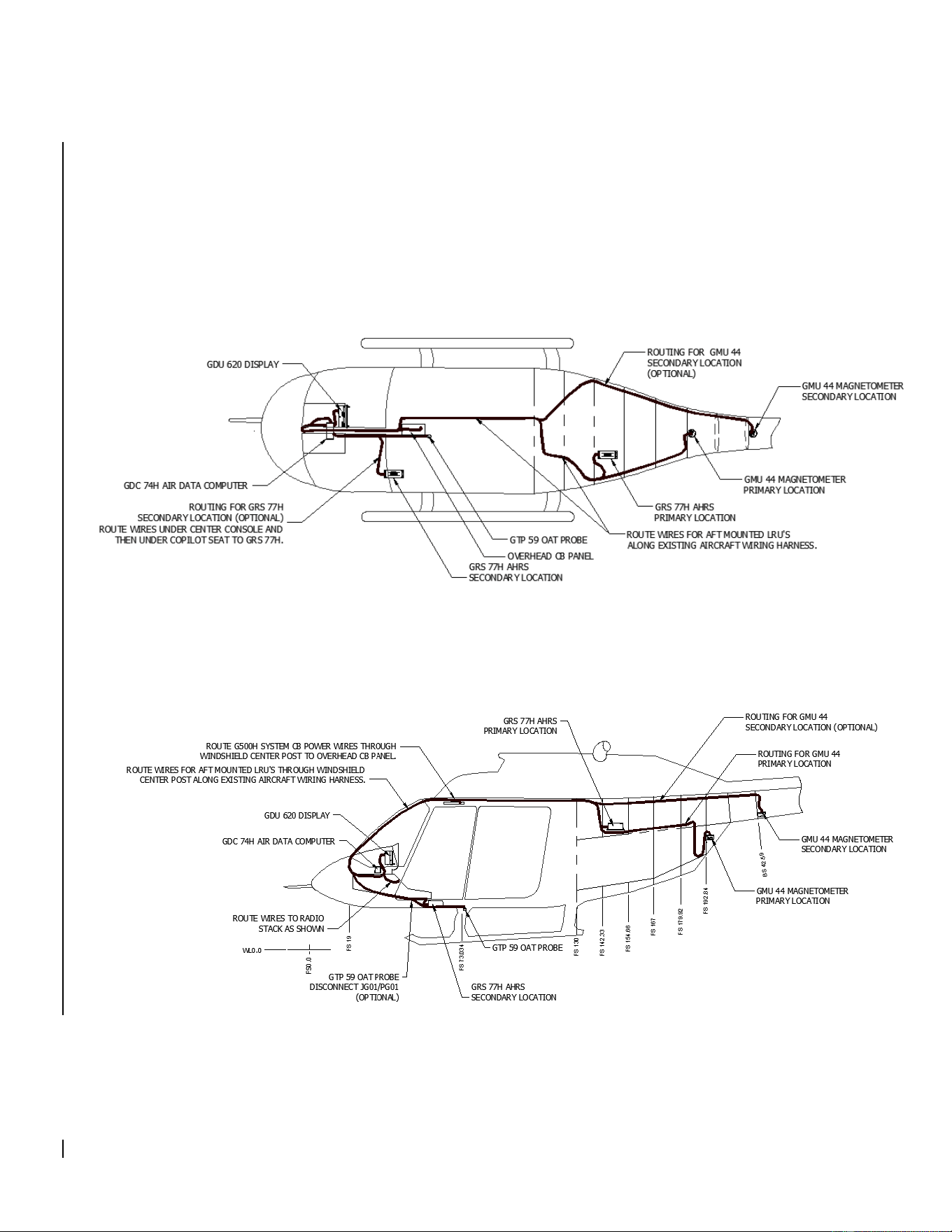
2.8 Diagrams
A rotorcraft specific LRU location and wire routing diagram is included below. A circuit breaker table is
included below. Installation locations for the GRS 79H and GSU 75H are the same as the GRS 77H, in
addition, installation locations for the GDC 72H are the same as the GDC 74H. Point to point wiring
diagrams are in Appendix D of the G500H STC Installation Manual and Appendix C of the G500H STC
Installation Manual Addendum. Refer to the G500H Post-Installation Checkout Log retained in the
rotorcraft permanent records for a list of the interfaced equipment and port configurations.
Top View:
Side View:
G500H Flight Display System 190-01150-11 Rev. 5
Instructions for Continued Airworthiness Bell 206A/B Series Page 30 of 33
The installed G500H equipment can be accessed as described below:
LRU
FS
WL
BL
Location
Notes
GDU 620
38.6
43.3
6.3
Primary
Access or remove by removing the six screws in the
bezel of the GDU 620
GDC 72H/74H
32.8
37.6
0.0
Primary
Access or remove by lowering instrument console at
its hinge point and removing the top instrument
console cowling
GRS 77H/79H
GSU 75H
151.4
54.7
-10.3
Primary
Access or remove by opening the baggage
compartment and removing the access panel located
on the ceiling of the baggage compartment
60.4
20.0
-18.6
Secondary
Access or remove by removing the cushion from the
co-pilots seat and the panel on top of the seat
pedestal
GMU 44
196.3
59.5
0.0
Primary
Access or remove by opening the baggage
compartment, removing the screws on the aft wall of
the baggage compartment which hold in place the
plastic baggage compartment extension, then remove
the baggage compartment extension
217.5
64.8
0.0
Secondary
Access or remove by removing the bolts from the
access panel on the pilots side of the aircraft at the
juncture of the tail boom and fuselage
Table 2-6: Circuit Breaker Labels
LRU
Circuit
Breaker Label
GDU 620
PFD
GDC 72H/74H
ADC
GRS 77H/79H
AHRS
GSU 75H
ADAHRS

G500H Flight Display System 190-01150-11 Rev. 5
Instructions for Continued Airworthiness Bell 206A/B Series Page 31 of 33
2.9 Special Inspection Requirements
2.9.1 Post-Lightning Strike Inspection
In the event of a suspected or actual lightning strike to the aircraft, both the GTP 59 OAT Probe and
GMU 44 Magnetometer shall be inspected.
2.9.1.1 GTP 59 OAT
The probe and the surrounding installation shall be inspected to ensure that there is no structural
damage around the areas where lightning may have attached. If there is visible sign of damage to the
probe then it must be replaced.
Verify that OAT is displayed on the GDU 620 PFD normally.
2.9.1.2 GMU 44
A magnetic inference check shall be performed in accordance with Section 6.3.7 of the Installation
Manual Addendum G500H Part 27 AML STC. The purpose of this check is to ensure the structure
around the GMU 44 did not get magnetized by the lightning event to the point of affecting GMU 44
performance.
2.10 Application of Protective Treatments
For detail on protective treatments, see the Bell Standard Practices Manual BHT-ALL-SPM, Chapter 3
for corrosion protection and Chapter 4 for painting.
2.11 Special Tools
For electrical bonding testing, a milliohm meter with an accuracy of ± 0.1 milliohms or better is required.
2.12 Additional Instructions
None
2.13 Overhaul Period
The system does not require overhaul at a specific time period. Power on self-test and continuous BIT
will monitor the health of the G500H system. If any LRU indicates an internal failure, the unit may be
removed and replaced. See the troubleshooting section contained in Section 2.6 of this document or
Section 6 of the G500H STC Installation Manual, listed under reference documentation in paragraph 2.1
of this document.
2.14 ICA Revision and Distribution
This document is required for maintaining the continued airworthiness of the rotorcraft. Garmin Dealers
may obtain the latest revision of this document at the Garmin Dealer Resource Center website.
Dealers are notified of manual revision changes by way of a Garmin Service Bulletin.
Owners and operators may obtain the latest revision of this document at www.flyGarmin.com or by
contacting a Garmin dealer. Garmin contact information is available at www.flyGarmin.com.

G500H Flight Display System 190-01150-11 Rev. 5
Instructions for Continued Airworthiness Bell 206A/B Series Page 32 of 33
2.15 Assistance
FAA Flight Standards Inspectors or the certificate holder’s PMI have the required resources to respond
to questions regarding this ICA. In addition, the customer may refer questions regarding this equipment
and its installation to the manufacturer, Garmin. Garmin customer assistance may be contacted during
normal business hours via telephone 913-397-8200 or email from the Garmin web site at
www.garmin.com.
2.16 Implementation and Record Keeping
Modification of an rotorcraft by this Supplemental Type Certificate obligates the rotorcraft operator to
include the maintenance information provided by this document in the operator’s rotorcraft maintenance
manual and/or the operator’s rotorcraft scheduled maintenance program.