

Visit our website at: http://www.harborfreight.com
email our technical support at: [email protected]
57436
18" GAS CHAINSAW
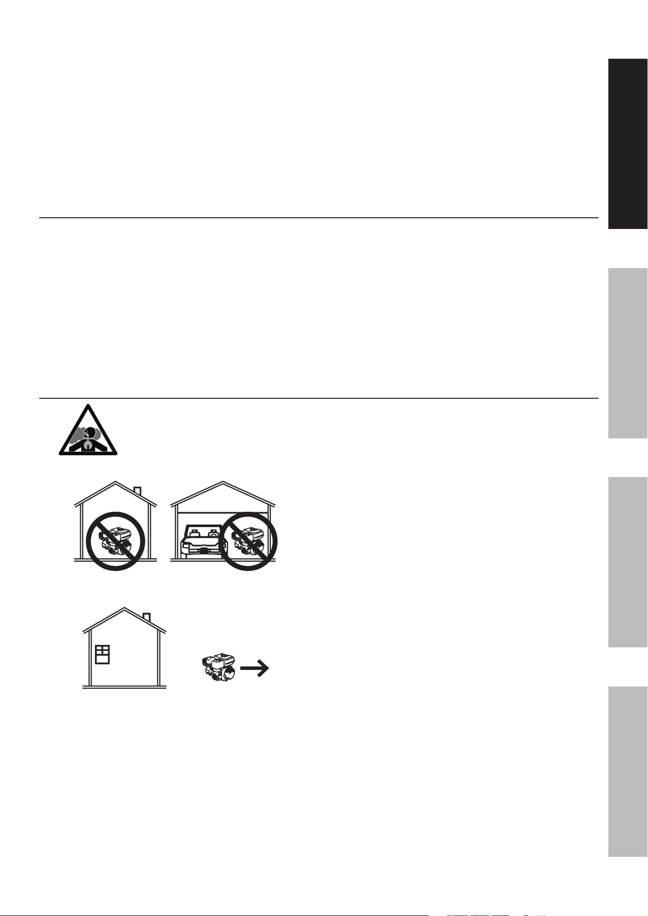
using an engine indoors
Can KiLL yOu in MinuTeS.
engine exhaust contains carbon monoxide.
This is a poison you cannot see or smell.
neVer use inside
a home or garage,
eVen iF doors and
windows are open.
Only use OuTSiDe
and far away from
windows, doors,
and vents.
42 cc
l
2-STROKE
Owner’s Manual & Safety Instructions
Save This Manual Keep this manual for the safety warnings and precautions, assembly,
operating, inspection, maintenance and cleaning procedures. Write the product’s serial number in the
back of the manual near the assembly diagram (or month and year of purchase if product has no number).
Keep this manual and the receipt in a safe and dry place for future reference. 23g
When unpacking, make sure that the product is intact
and undamaged. If any parts are missing or broken,
please call 1-888-866-5797 as soon as possible.
Copyright
©
2023 by Harbor Freight Tools
®
. All rights reserved.
No portion of this manual or any artwork contained herein may be reproduced in
any shape or form without the express written consent of Harbor Freight Tools.
Diagrams within this manual may not be drawn proportionally. Due to continuing
improvements, actual product may differ slightly from the product described herein.
Tools required for assembly and service may not be included.
Read this material before using this product.
Failure to do so can result in serious injury.
SAVE THIS MANUAL.

Page 2 For technical questions, please call 1-888-866-5797. ITEM 57436
Table of Contents
Specifications ............................................................2
Safety ........................................................................4
Setup .........................................................................8
Operation .................................................................. 12
Maintenance .............................................................19
Troubleshooting ........................................................ 24
Parts List and Diagram .............................................26
Warranties ................................................................30
Specifications
Engine
Displacement 42 cc (41.9 cm
3)
Engine Type
Single Cylinder
2-stroke
Max Engine Power 1.7 kW
Cooling System Forced air cooled
Fuel
Type
87+ octane stabilizer-treated
unleaded gasoline containing no
more than 10% ethanol (E10)
mixed
with 2-Stroke oil (see below)
Capacity 9.5 fl. oz.
Oil
Type
2-Stroke oil must meet either
JASO M345 FD or ISO-L-EGD
requirements for air-cooled engines,
synthetic
Ratio
50:1 gasoline-to-oil ratio
2.6 oz oil per gallon of gasoline
Bore x Stroke 41.5 mm x 31 mm
Compression Ratio 11:1
Spark Plug
Type
Champion
®
RCJ7Y / Torch
®
L7RTC
Bosch
®
L8RTF / NGK
®
BPMR7A
DENSO
®
W22MPR
Gap 0.02"
Speed
Idle 3000 ± 400 RPM
Maximum 1200/min
Chainsaw
Saw Chain
Length 18"
Pitch 0.375"
Gauge 0.050"
Model Oregon 91P062X
Guide Bar
Length 18"
Model Oregon 180SDEA041
Lubrication
Type Bar and chain oil
Capacity 7.8 fl. oz.
The emissions control system for this Engine is warranted for standards set by the
U.S. Environmental Protection Agency. For warranty information, refer to the last pages of this manual.
Page 3For technical questions, please call 1-888-866-5797.ITEM 57436
SaFeTySeTupOperaTiOnMainTenanCe
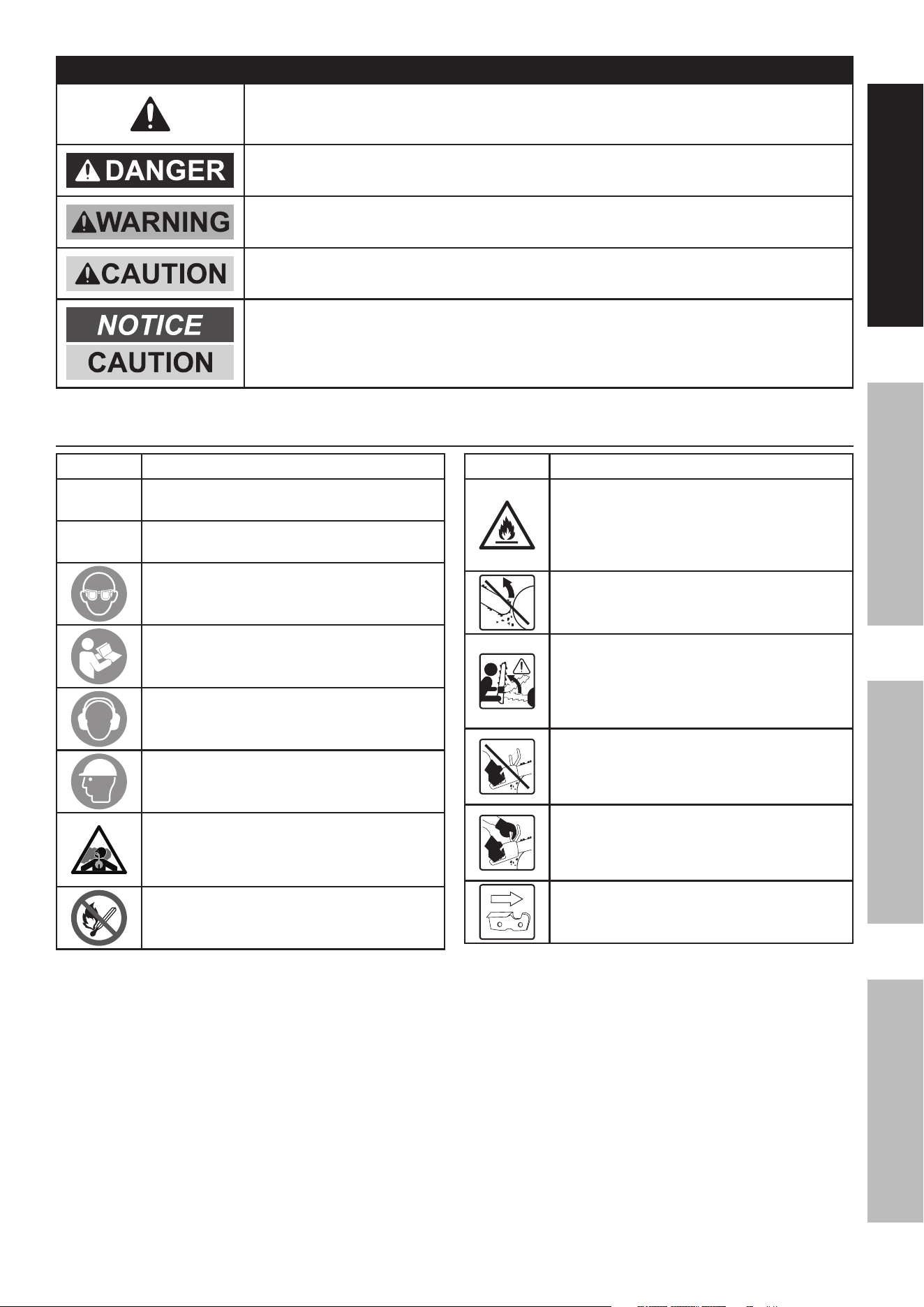
WarninG SyMBOLS anD DeFiniTiOnS
This is the safety alert symbol. It is used to alert you to potential
personal injury hazards. Obey all safety messages that
follow this symbol to avoid possible injury or death.
Indicates a hazardous situation which, if not avoided,
will result in death or serious injury.
Indicates a hazardous situation which, if not avoided,
could result in death or serious injury.
Indicates a hazardous situation which, if not avoided,
could result in minor or moderate injury.
Addresses practices not related to personal injury.
Symbol Definitions
Symbol property or Statement
rpM
Revolutions Per Minute
Hp
Horsepower
WARNING marking concerning
Risk of Eye Injury. Wear ANSI-approved
safety goggles with side shields.
Read the manual before
set-up and/or use.
WARNING marking concerning
Risk of Hearing Loss.
Wear hearing protection.
Wear head protection.
WARNING marking concerning
Risk of Respiratory Injury.
Operate engine OUTSIDE and far away
from windows, doors, and vents.
WARNING marking concerning
Risk of Fire while handling fuel.
Do not smoke while handling fuel.
Symbol property or Statement
WARNING marking concerning
Risk of Fire.
Do not refuel while operating.
Keep flammable objects
away from engine.
WARNING marking concerning Risk
of Kickback. Contact of the guide bar
tip with any object should be avoided.
WARNING marking concerning
Risk of Kickback. Tip contact
can cause the guide bar to move
suddenly upward and backward,
which can cause serious injury.
WARNING marking concerning
Risk of Loss of Control.
Do not operate the chainsaw
with only one hand.
WARNING marking concerning
Risk of Loss of Control.
Always use two hands when
operating the chainsaw.
WARNING marking concerning
Saw Chain Orientation. Cutters
must face in direction of rotation.

Page 4 For technical questions, please call 1-888-866-5797. ITEM 57436
SaFeTy SeTup OperaTiOn MainTenanCe
iMpOrTanT SaFeTy inSTruCTiOnS
SaVe THeSe inSTruCTiOnS –
This manual contains important instructions that should be followed
during setup, operation and maintenance of the chainsaw.
Kickback Safety precautions
WarninG! Kickback may occur when the nose or
tip of the guide bar touches an object, or when the
wood closes in and pinches the saw chain in the cut.
Tip contact in some cases may cause a lightning-fast
reverse reaction, kicking the guide bar up and back
toward the operator. Pinching the saw chain along the
top of the guide bar may push the guide bar rapidly
back toward the operator. Either of these reactions
may cause you to lose control of the saw, which
could result in serious personal injury. Do not rely
exclusively upon the safety devices built into your saw.
As a chainsaw user, you should take several steps to
keep your cutting jobs free from accident or injury.
a. With a basic understanding of kickback, you
can reduce or eliminate the element of surprise.
Sudden surprise contributes to accidents.
b. Keep a good firm grip on the saw with both
hands, the right hand on the rear handle
and the left hand on the front handle, when
the engine is running. Use a firm grip with
thumbs and fingers encircling the chain saw
handles. A firm grip will help reduce kickback
and maintain control of the saw. Don‘t let go.
c. Make sure that the area in which you are
cutting is free from obstructions. Do not
let the nose of the guide bar contact a log,
branch, or any other obstruction that could
be hit while you are operating the saw.
d. Cut at high engine speeds.
e. Do not overreach or cut above shoulder height.
f. Follow the manufacturer’s sharpening and
maintenance instructions for the saw chain.
g. Only use replacement bars and chains specified
by the manufacturer or the equivalent.
Other Safety precautions
• Do not operate a chain saw with one hand!
Serious injury to the operator, helpers,
bystanders, or any combination of these
persons may result from one-handed operation.
• A chain saw is intended for two-handed use.
• Do not operate a chain saw
when you are fatigued.
• Use safety footwear; snug-fitting clothing;
protective gloves; and eye, hearing,
and head protection devices.
• Use caution when handling fuel. Mix and pour
fuel outdoors where there are no sparks and
flames. Slowly remove the fuel cap only after
stopping the engine and allowing the chain saw
to cool. Do not smoke while fueling or mixing
fuel. Move the chain saw at least 10 feet (3 m)
from the fueling point before starting the engine.
• Do not allow other persons to be near
the chain saw when starting or cutting
with the chain saw. Keep bystanders
and animals out of the work area.
• Do not start cutting until you have a clear
work area, secure footing, and a planned
retreat path from the falling tree.
• Keep all parts of your body away from the
saw chain when the engine is running.
• Before you start the engine, make sure that
the saw chain is not contacting anything.
• Carry the chain saw with the engine stopped,
the guide bar and saw chain to the rear,
and the muffler away from your body.
• Do not operate a chain saw that is damaged,
improperly adjusted, or not completely
and securely assembled. Be sure that
the saw chain stops moving when the
throttle control trigger is released.
• Shut off the engine before setting
the chain saw down.
• Use extreme caution when cutting small-
size brush and saplings because slender
material may catch the saw chain and be
whipped toward you or pull you off balance.
• When cutting a limb that is under tension, be
alert for spring back so that you will not be struck
when the tension in the wood fibers is released.
• Keep the handles dry, clean, and
free of oil or fuel mixture.
• Operate the chain saw only in
well-ventilated areas.
Page 5For technical questions, please call 1-888-866-5797.ITEM 57436
SaFeTySeTupOperaTiOnMainTenanCe
• Do not operate a chain saw in a tree unless you
have been specifically trained to do so. All chain
saw service, other than the items listed in the
operator’s manual(s) maintenance instructions,
should be performed by competent chain saw
service personnel. (For example, if improper
tools are used to remove the flywheel or if an
improper tool is used to hold the flywheel in
order to remove the clutch, structural damage
to the flywheel could occur and subsequently
could cause the flywheel to burst.)
• Allow the chain saw to cool before
performing maintenance or adjustments.
• When transporting your chain saw, use
the appropriate guide-bar cover.
Set up precautions
1. Gasoline fuel and fumes are flammable, and
potentially explosive. Use proper fuel storage
and handling procedures. Do not store fuel
or other flammable materials nearby.
2. Have multiple ABC class fire extinguishers nearby.
3. Operation of this equipment may create sparks that
can start fires around dry vegetation.
A spark arrestor may be required. The operator
should contact local fire agencies for laws or
regulations relating to fire prevention requirements.
4. Set up and use only on a flat, level,
well-ventilated surface.
5. Wear ANSI-approved safety goggles, heavy-duty
work gloves, and dust mask/respirator during set up.
6. Use only lubricants and fuel recommended
in the Specifications chart of this manual.
Operating precautions
1. CarBOn MOnOXiDe HaZarD
using an engine indoors
Can KiLL yOu in MinuTeS.
Engine exhaust contains
carbon monoxide. This is a poison
you cannot see or smell.
NEVER use inside a home or garage,
EVEN IF doors and windows are open.
Only use OUTSIDE and far away from windows,
doors, and vents.
2. Keep children away from the equipment,
especially while it is operating.
3. Fire Hazard! Do not fill fuel tank while engine is
running. Do not operate if gasoline has been spilled.
Clean spilled gasoline before starting engine.
Do not operate near pilot light or open flame.
4. Do not touch engine during use.
Let engine cool down after use.
5. Never store fuel or other flammable
materials near the engine.
6. Only use a suitable means of transport and
lifting devices with sufficient weight bearing
capacity when transporting the equipment.
7. Secure the equipment on transport vehicles to
prevent it from rolling, slipping, and tilting.
8. Industrial applications must follow
OSHA requirements.
9. Do not leave the equipment unattended when it is
running. Turn off the equipment (and remove safety
keys, if available) before leaving the work area.
10. The equipment can produce high noise levels.
Prolonged exposure to noise levels
above 85 dBA is hazardous to hearing.
Wear ear protection when operating the chain saw
or when working nearby while it is operating.
11. People with pacemakers should consult their
physician(s) before use. Electromagnetic fields in
close proximity to a heart pacemaker could cause
pacemaker interference or pacemaker failure.
Caution is necessary when near the
engine’s magneto or recoil starter.
12. Use only accessories that are recommended
by Harbor Freight Tools for your model.
Accessories that may be suitable for one
piece of equipment may become hazardous
when used on another piece of equipment.
13. Do not operate in explosive atmospheres,
such as in the presence of flammable
liquids, gases, or dust. Gasoline-powered
engines may ignite the dust or fumes.

Page 6 For technical questions, please call 1-888-866-5797. ITEM 57436
SaFeTy SeTup OperaTiOn MainTenanCe
14. Stay alert, watch what you are doing and use
common sense when operating this piece of
equipment. Do not use while tired or under the
influence of drugs, alcohol or medication.
15. Do not overreach. Keep proper footing and
balance at all times. This enables better control
of the equipment in unexpected situations.
16. Dress properly. Do not wear loose clothing or
jewelry. Keep hair, clothing and gloves away
from moving parts. Loose clothes, jewelry or
long hair can be caught in moving parts.
17. Parts, especially exhaust system components,
get very hot during use. Stay clear of hot parts.
18. Do not cover the equipment during operation.
19. Keep the equipment, engine, and
surrounding area clean at all times.
20. Do not smoke, or allow sparks, flames,
or other sources of ignition around the
equipment, especially when refuelling.
21. Use the equipment, accessories, etc., in
accordance with these instructions and in the
manner intended for the particular type of
equipment, taking into account the working
conditions and the work to be performed.
Use of the equipment for operations different from
those intended could result in a hazardous situation.
22. Do not operate the equipment with known
leaks in the engine’s fuel system.
23. When spills of fuel or oil occur, they must be
cleaned up immediately. Dispose of fluids and
cleaning materials as per any local, state, or
federal codes and regulations. Store oil rags in
a bottom-ventilated, covered, metal container.
24. Keep hands and feet away from moving parts.
Do not reach over or across
equipment while operating.
25. Before use, check for misalignment or binding of
moving parts, breakage of parts, and any other
condition that may affect the equipment’s operation.
if damaged, have the equipment serviced
before using. Many accidents are caused
by poorly maintained equipment.
26. Use the correct equipment for the application.
Do not modify the equipment and do not use the
equipment for a purpose for which it is not intended.
Service precautions
1. Before service, maintenance, or cleaning:
a. Turn the engine switch to its “OFF” position.
b. allow the engine to completely cool.
c. Then, remove the spark plug cap
from the spark plug.
2. Keep all safety guards in place and in
proper working order. Safety guards include
muffler, air cleaner, mechanical guards,
and heat shields, among other guards.
3. Do not alter or adjust any part of the
equipment or its engine that is sealed by the
manufacturer or distributor. Only a qualified
service technician may adjust parts that may
increase or decrease governed engine speed.
4. Wear ANSI-approved safety goggles,
heavy-duty work gloves, and
dust mask/respirator during service.
5. Maintain labels and nameplates on the equipment.
These carry important information.
If unreadable or missing, contact
Harbor Freight Tools for a replacement.
6. Have the equipment serviced by a qualified repair
person using only identical replacement parts.
This will ensure that the safety of the equipment
is maintained. Do not attempt any service or
maintenance procedures not explained in this
manual or any procedures that you are uncertain
about your ability to perform safely or correctly.
7. Store equipment out of the reach of children.
8. Follow scheduled engine and
equipment maintenance.
refueling:
1. Do not refill the fuel tank while the
engine is running or hot.
2. Do not smoke, or allow sparks, flames,
or other sources of ignition around the
equipment, especially when refuelling.
3. Do not fill fuel tank to the top.
Leave a little room for the fuel to expand as needed.
TO preVenT FueL LeaKaGe anD
Fire HaZarD, do not fill fuel above the
bottom of the Fuel Tank fill neck.
4. Refuel in a well-ventilated area only.
5. Wipe up any spilled fuel and allow excess
to evaporate before starting engine.
To prevent Fire, do not start the engine
while the smell of fuel hangs in the air.

Page 7For technical questions, please call 1-888-866-5797.ITEM 57436
SaFeTySeTupOperaTiOnMainTenanCe
Chain Saw Safety Warnings
1. Keep all parts of the body away from the
saw chain when the chain saw is operating.
Before you start the chain saw, make sure
the saw chain is not contacting anything.
A moment of inattention while operating
chain saws may cause entanglement of your
clothing or body with the saw chain.
2. always hold the chain saw with your right
hand on the rear handle and your left hand on
the front handle. Holding the chain saw with a
reversed hand configuration increases the risk
of personal injury and should never be done.
3. Hold the power tool by insulated gripping
surfaces only, because the saw chain
may contact hidden wiring. Saw chains
contacting a “live” wire may make exposed
metal parts of the power tool “live” and could
give the operator an electric shock.
4. Wear safety glasses and hearing protection.
Further protective equipment for head,
hands, legs and feet is recommended.
Adequate protective clothing will reduce
personal injury by flying debris or
accidental contact with the saw chain.
5. Do not operate a chain saw in a tree.
Operation of a chain saw while up in a
tree may result in personal injury.
6. always keep proper footing and operate
the chain saw only when standing on fixed,
secure and level surface. Slippery or unstable
surfaces such as ladders may cause a loss
of balance or control of the chain saw.
7. When cutting a limb that is under tension
be alert for spring back. When the tension
in the wood fibres is released the spring
loaded limb may strike the operator and/
or throw the chain saw out of control.
8. use extreme caution when cutting
brush and saplings. The slender material
may catch the saw chain and be whipped
toward you or pull you off balance.
9. Follow instructions for lubricating, chain
tensioning and changing accessories.
Improperly tensioned or lubricated chain may
either break or increase the chance for kickback.
10. Cut wood only. Do not use chain saw for
purposes not intended.
For example: do not use chain saw for cutting
plastic, masonry or non-wood building materials.
Use of the chain saw for operations different than
intended could result in a hazardous situation.
11. Do not leave the tool unattended when it is running.
Turn off the tool before leaving the work area.
12. Chain saws shall be used in accordance with
the operating instructions and safety precautions
listed in the operator’s manual. It shall be the
responsibility of the owner to see that such
instructions and precautions are given to
every operator who uses the chain saw.
13. This product is not a toy.
Keep it out of reach of children.
14. The warnings, precautions, and instructions
discussed in this instruction manual cannot cover all
possible conditions and situations that may occur.
It must be understood by the operator that
common sense and caution are factors
which cannot be built into this product,
but must be supplied by the operator.
SaVe THeSe inSTruCTiOnS.

Page 8 For technical questions, please call 1-888-866-5797. ITEM 57436
SaFeTy SeTup OperaTiOn MainTenanCe
Set up
read the enTire iMpOrTanT SaFeTy inFOrMaTiOn section at the beginning of this manual
including all text under subheadings therein before set up or use of this product.
TO preVenT SeriOuS inJury:
Operate only with proper spark arrestor installed.
Operation of this equipment may create sparks that can start fires around dry vegetation.
a spark arrestor may be required.
The operator should contact local fire agencies for laws or regulations
relating to fire prevention requirements.
TO preVenT SeriOuS inJury FrOM aCCiDenTaL STarTinG: Make sure that the engine is switched OFF,
wait for the engine to cool, and unplug the spark plug wire before performing any procedure in this section.
At high altitudes, the engine’s carburetor, governor (if so equipped), and any other parts that control
the fuel-air ratio will need to be adjusted by a qualified mechanic to allow efficient high-altitude
use and to prevent damage to the engine and any other devices used with this product.
note: For additional information regarding the parts listed in the
following pages, refer to Parts List and Diagram on page 26.
Safety Device explanation
1. Hand Guard – A guard that protects your hand
on the Front Handle from the Saw Chain.
2. Chain Brake – A mechanical braking device
designed to quickly stop the Chainsaw and Chain
in the event of kickback. If kickback occurs, this
safety feature is activated when the operator’s
hand strikes the Hand Guard / Chain Brake Lever
and pushes it forward, stopping the Chain.
3. Trigger Lockout – A movable stop that
prevents the unintentional operation of
the Trigger until manually activated.
4. Low-Kickback Saw Chain – A low-kickback
saw chain is a chain that has met the kickback
performance requirements of
ANSI/OPEI 8175.1-2021 when tested according to
the provisions specified in ANSI/OPEI 8175.1-2021.
5. Spiked Bumper – The pointed teeth used
when felling or bucking to pivot the saw
and maintain position while sawing.
6. Guide bar – A part that supports and guides the saw
chain. Sprocket nose guide bars with the same
effective length, the same number of sprocket nose
teeth, the same nose radius, and the same pitch
may be considered to have the equivalent kickback
energy. Kickback energy of all guide bars may be
considered to be less for smaller nose radius sizes.
Page 9For technical questions, please call 1-888-866-5797.ITEM 57436
SaFeTySeTupOperaTiOnMainTenanCe
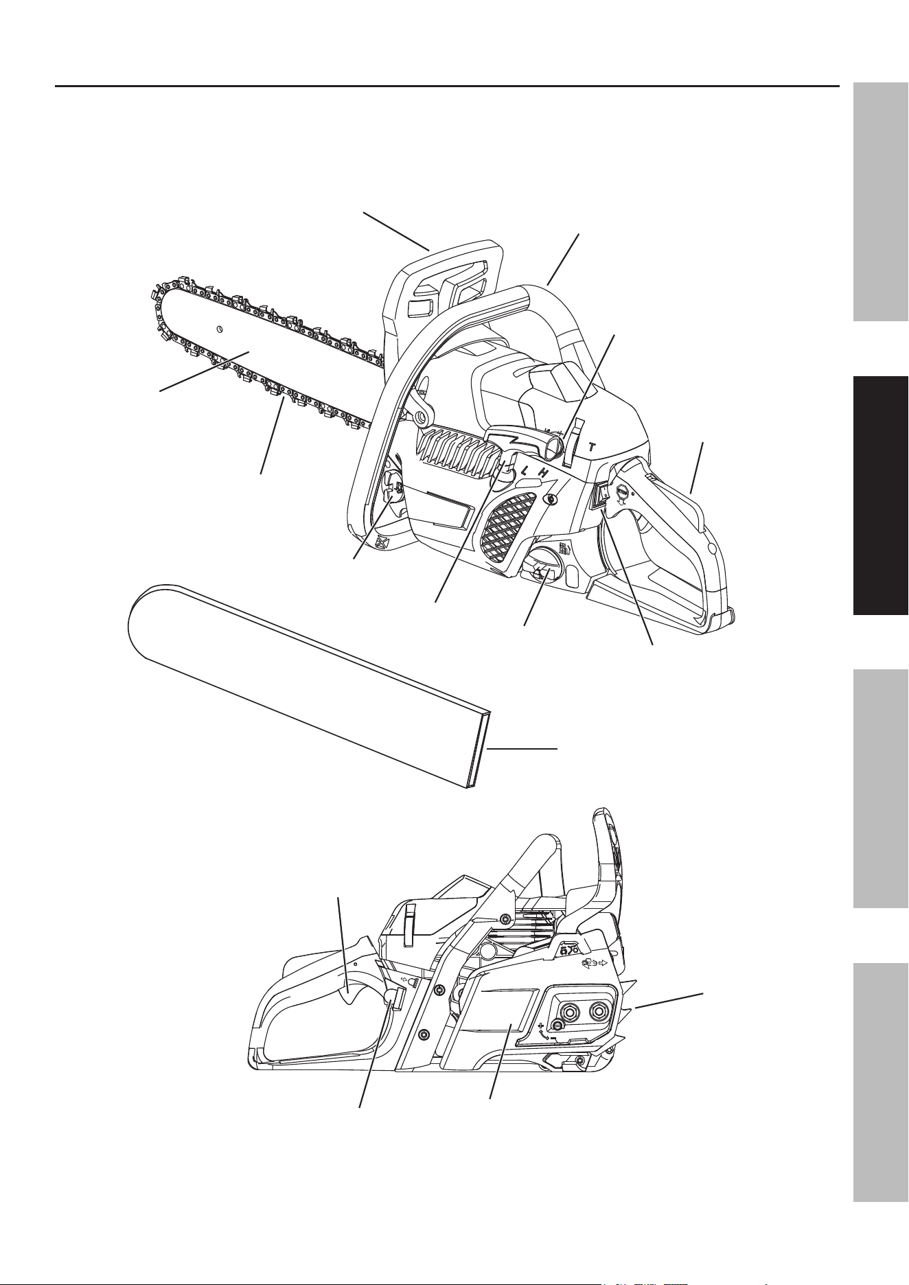
Components and Controls
Oil Tank
Cap
prime Bulb
Fuel Tank
Cap
Chain
Guide Bar
Guide Bar
Sheath
Spiked
Bumper
Saw Chain
Front Handle
Choke
Knob
Trigger
Lockout
Stop engine
Switch
Trigger
Hand Guard / Chain
Brake Lever
Starter
Handle
Drive
Cover
Page 10 For technical questions, please call 1-888-866-5797. ITEM 57436
SaFeTy SeTup OperaTiOn MainTenanCe
Guide Bar and Saw Chain installation and adjustment
TO preVenT SeriOuS inJury FrOM aCCiDenTaL OperaTiOn:
Make sure that the engine is switched OFF, wait for the engine to cool, and unplug
the spark plug wire before performing any procedure in this section.
note: New Saw Chains often need to be tensioned several times during first use.
Check a new Saw Chain’s tension often when first using.
Follow the directions in the following sections for installing the Guide Bar and Saw Chain, for
checking and adjusting Saw Chain tension, and for replacing the Saw Chain when necessary.
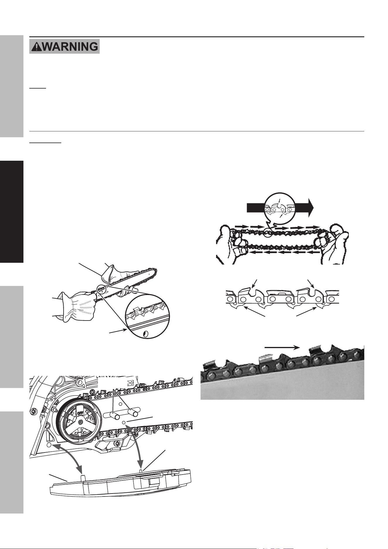
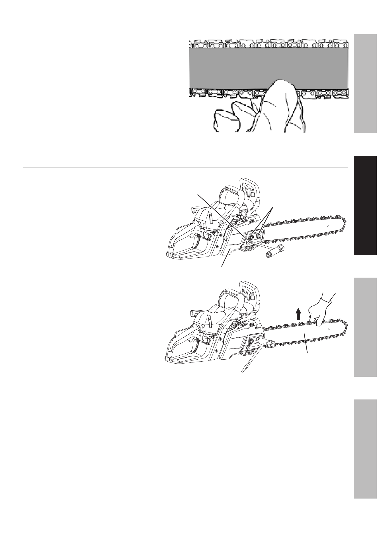
Guide Bar / Saw Chain installation/replacement
CauTiOn! Wear heavy-duty work gloves when handling Saw Chain.
1. BeFOre FirST uSe: Soak the Saw Chain
overnight in bar and chain oil (sold separately).
2. Pull the Hand Guard / Chain Brake
Lever back toward the rear to make
sure the chain brake is not on.
3. Loosen and remove the Drive Cover Nuts,
then remove the Drive Cover from the Saw.
4. Place the Saw Chain over the Guide Bar.
The cutters of the Saw Chain must face
away from the Chainsaw along the top
edge of the Guide Bar. Fit the Drive Links
into the groove around the Guide Bar.
Guide Bar groove
5. Place the slotted end of the Chain Guide Bar over
the Guide Bar Bolts and place the Saw Chain
over the Drive Sprocket. Refer to Figure A.
Lower Hole
Guide
Bar
Chain Chain
Tension pinTension pin
Drive
Cover
Guide Guide
Bar BoltsBar Bolts
Figure a: installing Guide Bar and Chain
6. Check again that the Saw Chain cutters are aligned
properly and the Saw Chain Drive Links are seated
completely in the slot of the Guide Bar. The
cutters of the Saw Chain must face away from the
Chainsaw along the top edge of the Guide Bar.
CuTTerS MuST FaCe in
DireCTiOn OF rOTaTiOn
Tip of
Bar
Cutter
Drive Link
Cutters Depth Gauge
Drive Links
Direction of Saw
Chain Cutters
Saw
Guide Bar
nose
Figure B: Saw Chain Orientation
7. Replace the Drive Cover, making sure the Chain
Tension Pin on the Cover is inserted into the lower
hole on the Guide Bar as shown in Figure A.
Replace the Drive Cover Nuts and tighten so that the
Cover is snug, but not tight. Tension the Saw Chain
following the steps in Checking Saw Chain Tension
and Adjusting Saw Chain Tension on page 11.
Page 11For technical questions, please call 1-888-866-5797.ITEM 57436
SaFeTySeTupOperaTiOnMainTenanCe
Checking Saw Chain Tension
1. Before using, check the Saw Chain tension.
2. While wearing heavy-duty gloves, use your index
finger and thumb to carefully grab the Saw Chain
in the middle section under the Chain Guide Bar.
3. Pull the Saw Chain away from the Guide Bar.
4. The Saw Chain should snap back against
the Guide Bar. The Chain should fit snugly
in the groove of the Chain Guide Bar, yet
you should still be able to slide the chain
along the Chain Guide Bar by hand.
5. There should be no sagging between the Guide Bar
and Saw Chain on the underside of the Guide Bar.
Figure C: Checking Saw Chain Tension
adjusting Saw Chain Tension
1. Loosen the Drive Cover Nuts on the Drive
Cover. It is not necessary to remove the
Drive Cover to adjust chain tension.
2. Turn the Chain Tension Screw
clockwise to increase chain tension and
counterclockwise to decrease tension.
3. Tighten the Drive Cover Nuts on
the Drive Cover while holding
the Chain Guide Bar up.
4. Check the Saw Chain tension again
following steps 2 through 5 under
Checking Saw Chain Tension above.
If needed, repeat the adjusting steps
to achieve the correct tension.
Chain Chain
Tension Tension
ScrewScrew
Chain Chain
Guide BarGuide Bar
Drive Cover
DDrive rive
Cover Cover
nutsnuts
Figure D: adjusting Saw Chain Tension
Page 12 For technical questions, please call 1-888-866-5797. ITEM 57436
SaFeTy SeTup OperaTiOn MainTenanCe
Operation
read the enTire iMpOrTanT SaFeTy inFOrMaTiOn section at the beginning of this manual
including all text under subheadings therein before set up or use of this product.
pre-Start Checks
Inspect engine and equipment looking for damaged, loose, and missing parts before set up and starting.
If any problems are found, do not use equipment until fixed properly.
Checking and Filling Fuel
WarninG! TO preVenT SeriOuS
inJury FrOM Fire:
Fill the fuel tank in a well-ventilated area
away from ignition sources. If the engine
is hot from use, shut the engine off and
wait for it to cool before adding fuel. Do not smoke.
1. Clean the Fuel Tank Cap and the area around it.
2. Unscrew and remove the Fuel Tank Cap.
note: Do not use gasoline containing more than
10% ethanol (e10). Do not use e85 ethanol. add fuel
stabilizer to the gasoline or the Warranty is VOiD.
note: Do not use gasoline that has been stored in a
metal fuel container or a dirty fuel container. it can
cause particles to enter the carburetor, affecting
engine performance and/or causing damage.
iMpOrTanT: Your Warranty is VOID if the Engine’s
Fuel Tank is not filled with the proper mixture (50:1) of
unleaded gasoline and 2-cycle oil before each use.
2-Stroke oil must meet either JASO M345 FD or ISO-
L-EGD requirements for air-cooled engines, synthetic.
Before each use, check the fuel level. Do not run the
Engine with an improper unleaded gasoline/2-cycle oil
mixture. Running the Engine with an improper
mixture WILL permanently damage the Engine.
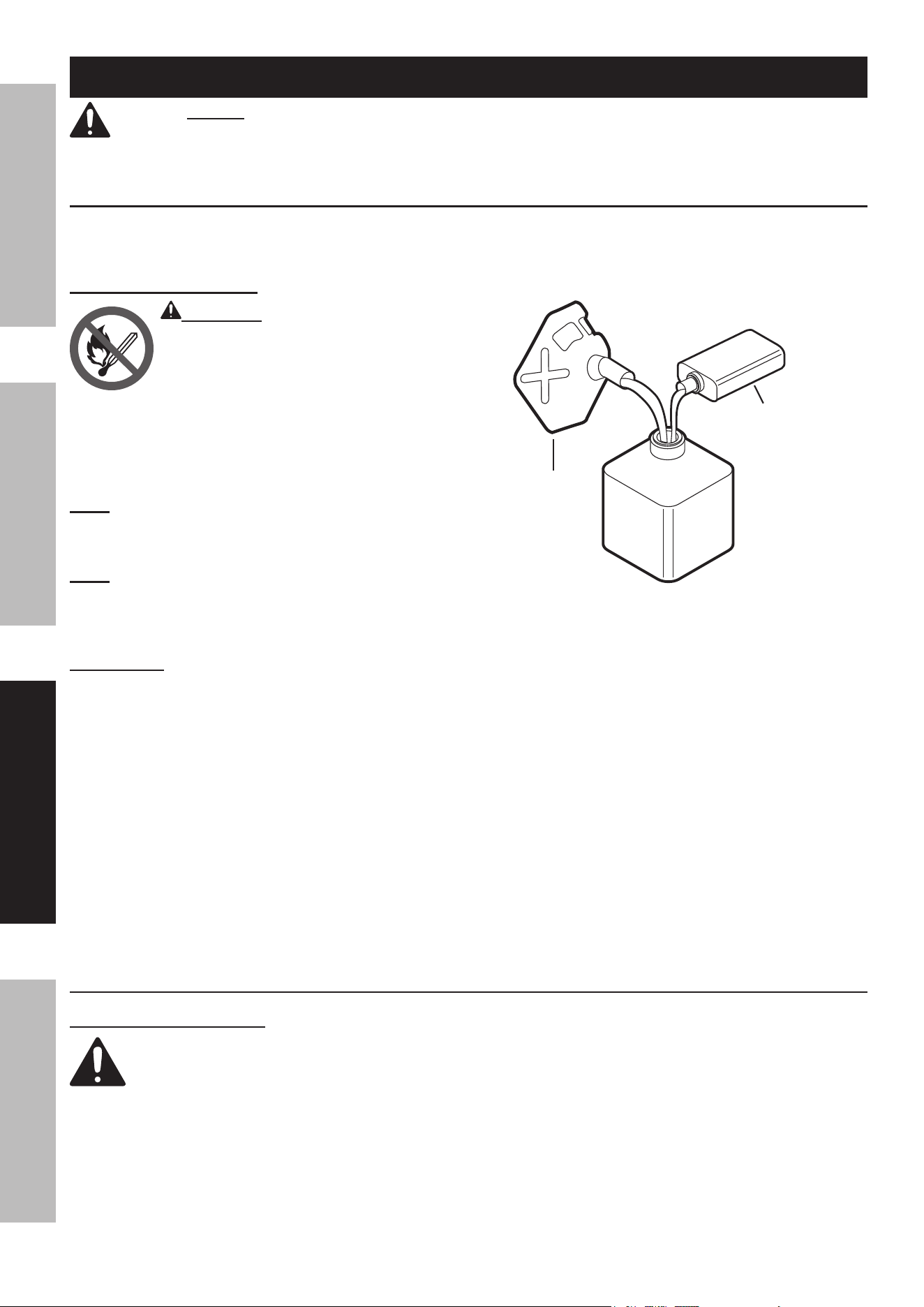
1 GaLLOn
unLeaDeD
GaSOLine
2.6 FLuiD OunCeS
2-CyCLe OiL
apprOVeD
COnTainer
Figure e: Fuel-Oil Mixture
3. To obtain the proper gasoline and 2-cycle oil
mixture, mix 2.6 fluid ounces of 2-cycle oil with
1 gallon of unleaded gasoline into an approved
container. Then gently agitate the container
to thoroughly mix the gasoline/2-cycle oil.
4. If needed, fill the Fuel Tank to about 1 inch under
the fill neck of the Fuel Tank with the pre-mixed
unleaded gasoline/2-cycle oil mixture.
5. Then replace the Fuel Tank Cap.
6. Wipe up any spilled fuel and allow excess
to evaporate before starting engine.
To prevent FIRE, do not start the engine
while the smell of fuel hangs in the air.
Starting the engine
Before Starting the engine
Before starting the engine:
a. inspect the equipment and engine.
b. Fill the engine with the proper amount and type of unleaded gasoline and 2-cycle oil mixture.
c. Fill the oil tank with the proper amount and type of bar and chain oil.
Page 13For technical questions, please call 1-888-866-5797.ITEM 57436
SaFeTySeTupOperaTiOnMainTenanCe
Manual Start
A “cold start” is when the engine is no
longer hot to the touch, typically at least
30 minutes after it has last been run.
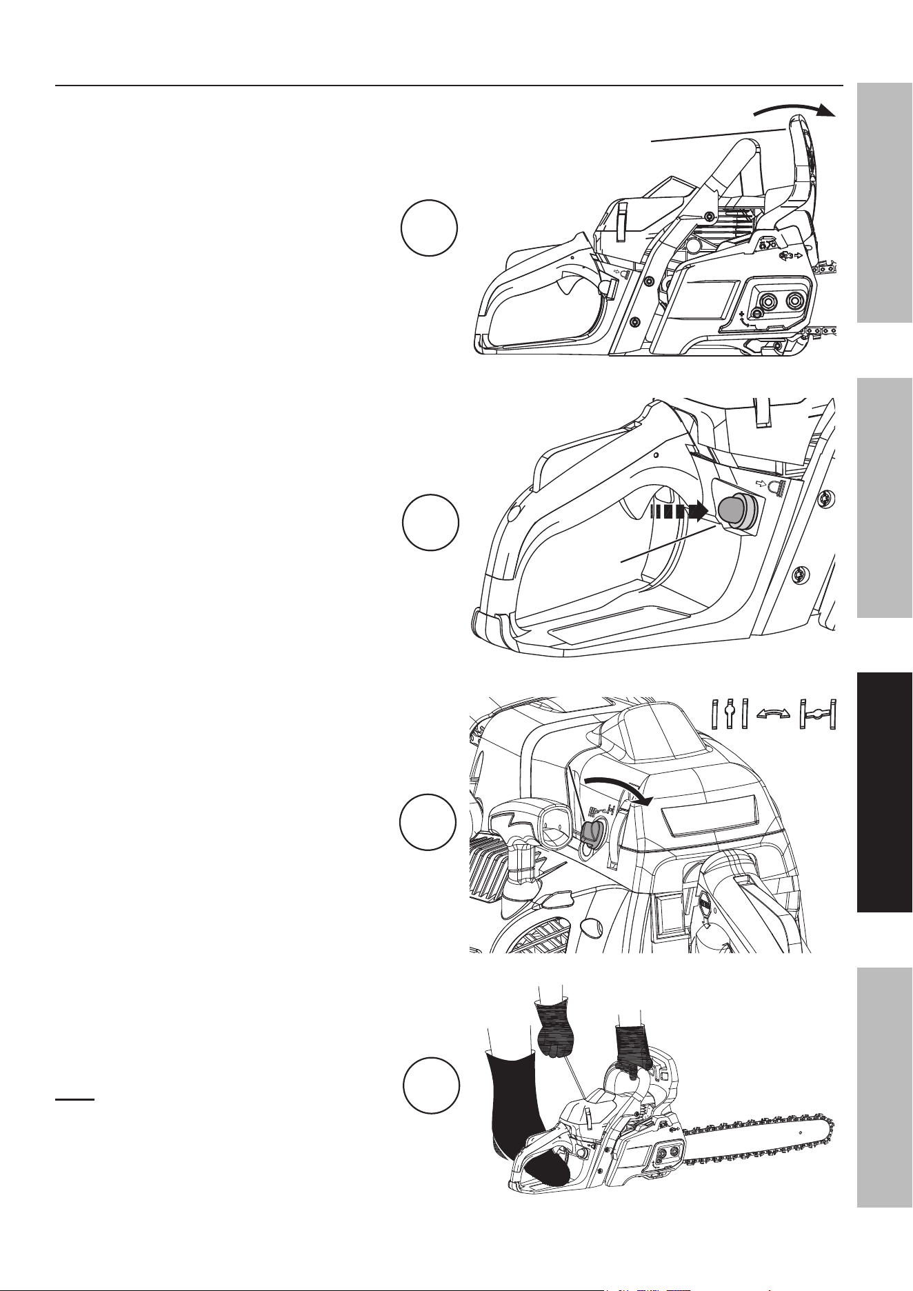
1. To start a cold Engine, ensure the Guide
Bar and Saw Chain are not touching or
near any object as Chain will spin during
startup. Push the Hand Guard / Chain Brake
Lever forward to engage the chain brake.
2. Press the Prime Bulb up to 10 times
until the Bulb begins to fill with fuel.
3. Turn the Choke Knob to the
START (closed) position.
4. Hold the Chain Saw securely on the ground.
Firmly grasp the Starter Handle and pull
it rapidly until the Engine sputters.
note: Do not let the Starter Handle snap
back against the Engine. Hold it as it
recoils so it doesn’t hit the Engine.
1
Hand Guard /
Chain Brake
Lever
engaged
prime
Bulb
2
Choke Choke
Knob Knob
3
run STarT
4
Page 14 For technical questions, please call 1-888-866-5797. ITEM 57436
SaFeTy SeTup OperaTiOn MainTenanCe
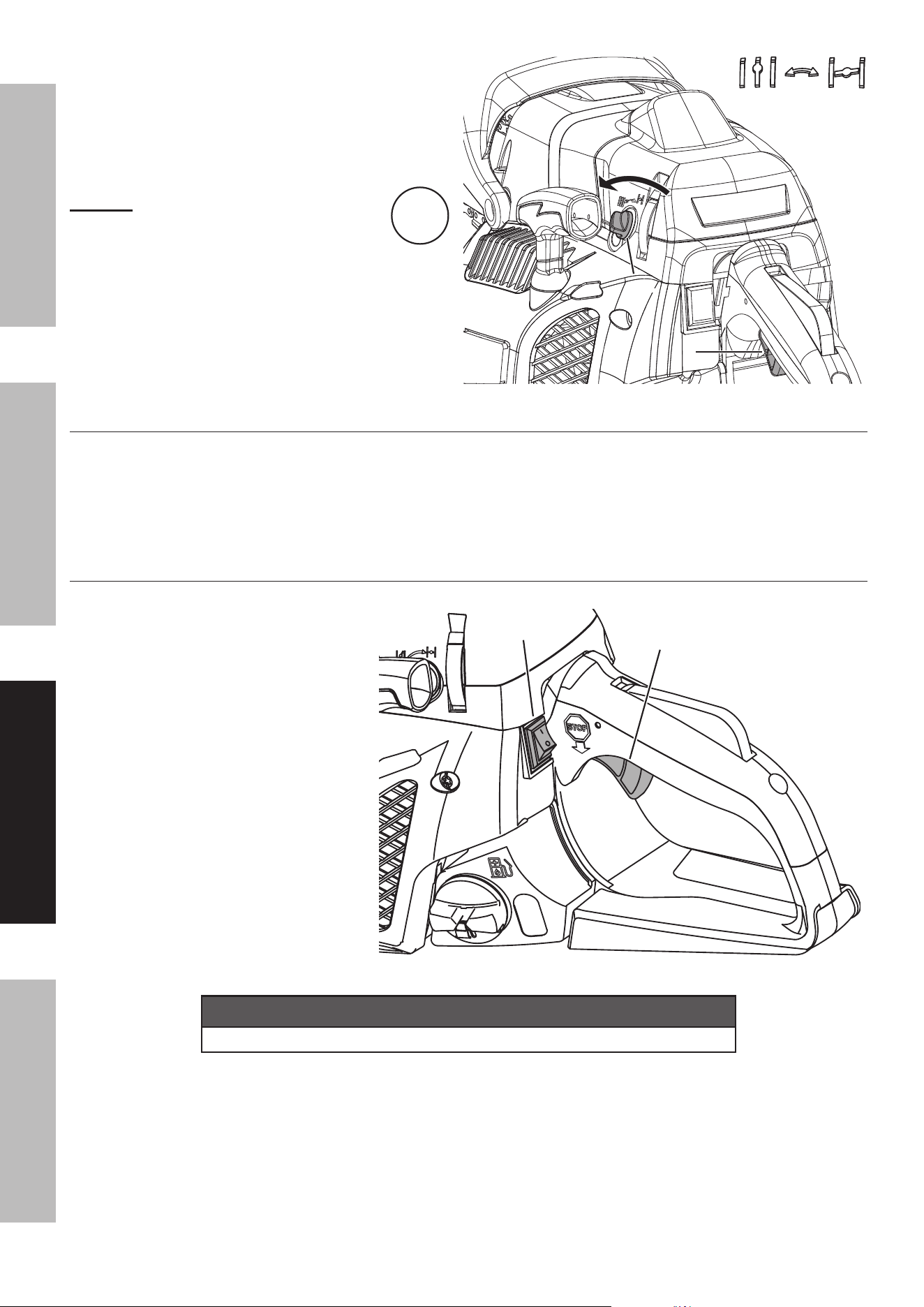
Stopping the engine
1. To stop the engine in an emergency,
release the Trigger and press
the Stop Engine Switch.
2. Under normal conditions, use
the following procedure:
a. Release the Trigger.
b. Let Engine idle for 10 – 30 seconds.
c. Press the Stop Engine Switch.
NOTICE
See Long-Term Storage on page 23 for complete storage instructions.
Stop engine
Switch
Trigger
5. Turn the Choke Knob to the RUN (open)
position—this will partially engage
the throttle to assist starting.
Pull the Starter Handle rapidly until the
Engine starts. Immediately disengage
the chain brake by pulling back on the
Hand Guard / Chain Brake Lever.
Caution! The Saw Chain will immediately
start spinning with the Engine running
at partial throttle.
Allow the Engine to run at partial throttle
for 5 seconds. Quickly squeeze and then
release theTrigger to disengage the throttle
assist and allow the Engine to idle.
Allow the Engine to warm up at idle for
60 seconds after each start-up so that
the Engine can stabilize before use.
To restart a Warm engine
Follow the starting instructions above with the following exception:
Omit the portion of Step 4 which states — Firmly grasp the Starter Handle and
pull it rapidly until the Engine sputters — and proceed to Step 5.
5
run STarT
TriggerTrigger
Choke Choke
KnobKnob
Page 15For technical questions, please call 1-888-866-5797.ITEM 57436
SaFeTySeTupOperaTiOnMainTenanCe
Workpiece and Work area Set up
1. Designate a work area that is clean and well lit.
The work area must not allow access by children
or pets to prevent distraction and injury.
2. There must not be objects, such as utility lines,
nearby that will present a hazard while working.
3. A first-time user should, as a minimum practice,
cut logs on a saw-horse or cradle
before cutting down trees.
General Operating instructions
1. Before first use and before each use thereafter,
remove the Oil Tank Cap. Inspect the Cap Gasket
for damage. Fill the Oil Tank to just below fill plug
with oil (not included). Refer to Specifications
chart on page 2 for oil type. Then replace
the Oil Tank Cap. Oil is automatically applied
to the Saw Chain during operation.
2. Start the Engine as detailed in Starting the
Engine on page 12. If necessary, adjust
Engine idle speed so Saw Chain does not
rotate at idle. To adjust, turn the Idle Adjusting
Screw (T) counterclockwise to lower idle speed
until Chain does not turn. Refer to Figure F.
idle adjusting
Screw (T)
Figure F: idle adjusting Screw
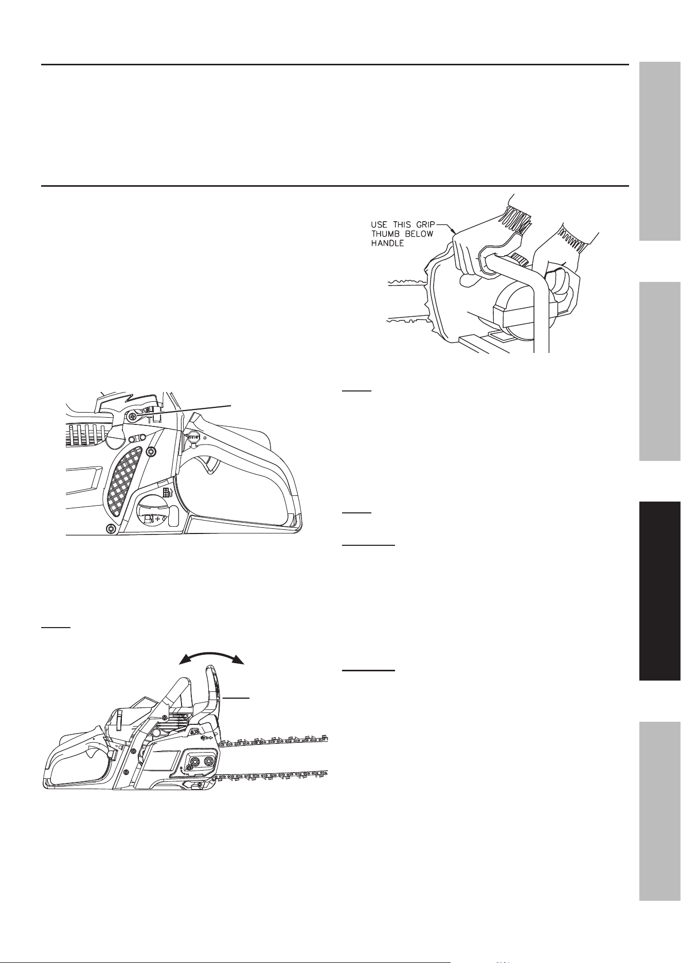
3. Place the Hand Guard / Chain Brake Lever in normal
operating (disengaged) position by pulling the Hand
Guard back toward the Handle. Refer to Figure G.
note: The Chainsaw will not operate unless the Hand
Guard / Chain Brake Lever is in the disengaged position.
DiSenGaGeD
enGaGeD
Hand Guard /
Chain Brake
Lever
Figure G: Hand Guard / Chain Brake Lever
4. Grasp the Handles with both hands. Always
grip the handle with the thumb and fingers
encircling the handle as shown in Figure H.
Figure H: Holding the Chainsaw
note: Front Hand Guard not shown.
5. Stand in front of the wood to be cut
with your feet firmly in place.
6. Grasp the Rear Handle to activate the
Trigger Lockout Switch, then squeeze and
hold the Trigger. Releasing the Trigger
will return the Engine to idling speed.
note: The Trigger cannot be activated unless
the Trigger Lockout Switch is depressed.
DanGer! To prevent serious injury and
death from kickback: Do not touch the
Guide Bar Nose to the wood.
7. When the Chainsaw reaches full speed, begin
cutting with a light, downward pressure against
the bottom mid-section of the Saw Chain.
Allow the Saw Chain to cut at its own rate.
Applying too much pressure can damage the tool.
DanGer! To prevent serious injury and death
from kickback: When cutting loose, round
wood stock, place the wood stock on a sawhorse,
in a cradle, or use a timberjack (all sold
separately) to avoid grabbing and throw back.
8. When cutting is complete release the Trigger,
allow the Engine to idle for 10 – 30 seconds,
then press the Stop Engine Switch. To prevent
accidents, place the Hand Guard / Chain Brake
Lever forward in its engaged position after use.
9. When the Saw has cooled completely, clean
thoroughly and cover the Chain Guide Bar with the
Chain Guide Bar Sheath. Store the tool indoors
out of children’s reach. See Long-Term Storage
on page 23 for complete storage instructions.
Page 16 For technical questions, please call 1-888-866-5797. ITEM 57436
SaFeTy SeTup OperaTiOn MainTenanCe
instructions concerning the proper techniques for
basic felling, limbing, and cross-cutting
Felling a Tree
When bucking and felling operations are being
performed by two or more persons at the same time,
the felling operations should be separated from the
bucking operation by a distance of at least twice the
height of the tree being felled. Trees should not be
felled in a manner that would endanger any person,
strike any utility line or cause any property damage.
If the tree does make contact with any utility line,
the company should be notified immediately.
The chainsaw operator should keep on the
uphill side of the terrain as the tree is likely
to roll or slide downhill after it is felled.
An escape path should be planned and cleared as
necessary before cuts are started. The escape path
should extend back and diagonally to the rear of
the expected line of fall as illustrated in Figure I.
Before felling is started, consider the natural lean
of the tree, the location of larger branches and the
wind direction to judge which way the tree will fall.
Remove dirt, stones, loose bark, nails,
staples and wire from the tree.
Felling Direction
Danger Zone
Danger Zone
escape
route
escape
route
Figure i: escape routes
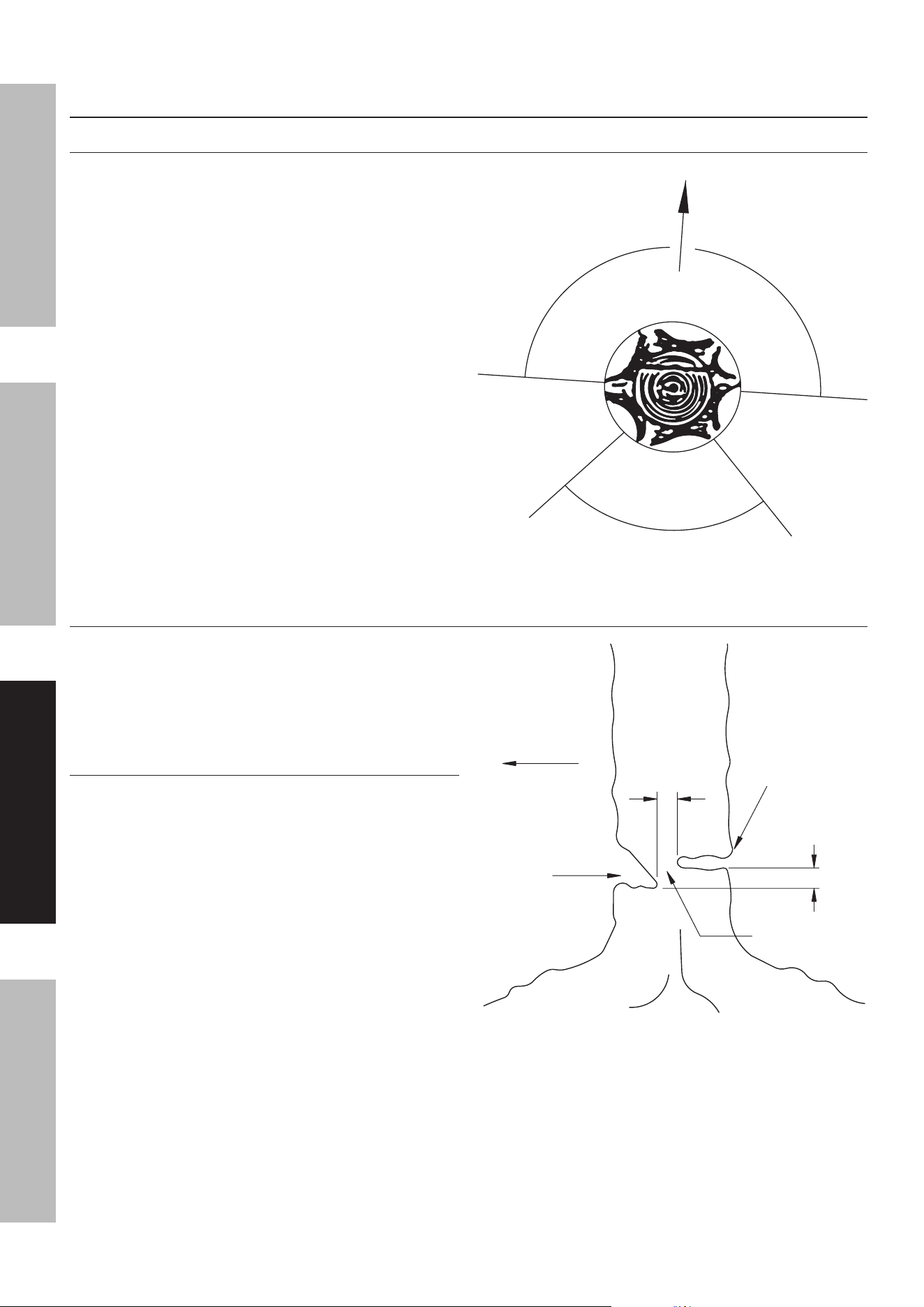
notching undercut
Make the notch 1/3 the diameter of the tree,
perpendicular to the direction of falls as illustrated in
Figure J. Make the lower horizontal notching cut first.
This will help to avoid pinching either the saw chain or
the guide bar when the second notch is being made.
Felling Back Cut
Make the felling back cut at least 2 inches higher
than the horizontal notching cut as illustrated in
Figure J. Keep the felling back cut parallel to the
horizontal notching cut. Make the felling back cut
so enough wood is left to act as a hinge. The hinge
wood keeps the tree from twisting and falling in the
wrong direction. Do not cut through the hinge.
As the felling gets close to the hinge, the tree
should begin to fall. If there is any chance that the
tree may not fall in desired direction or it may rock
back and bind the saw chain, stop cutting before
the felling back cut is complete and use wedges
of wood, plastic or aluminium to open the cut and
drop the tree along the desired line of fall.
When the tree begins to fall remove the chainsaw
from the cut, stop the motor, put the chainsaw
down, then use the retreat path planned. Be alert
for overhead limbs falling and watch your footing.
Direction of Fall
2"
2"
Felling Back Cut
Hinge
notch
Figure J: undercutting
Page 17For technical questions, please call 1-888-866-5797.ITEM 57436
SaFeTySeTupOperaTiOnMainTenanCe
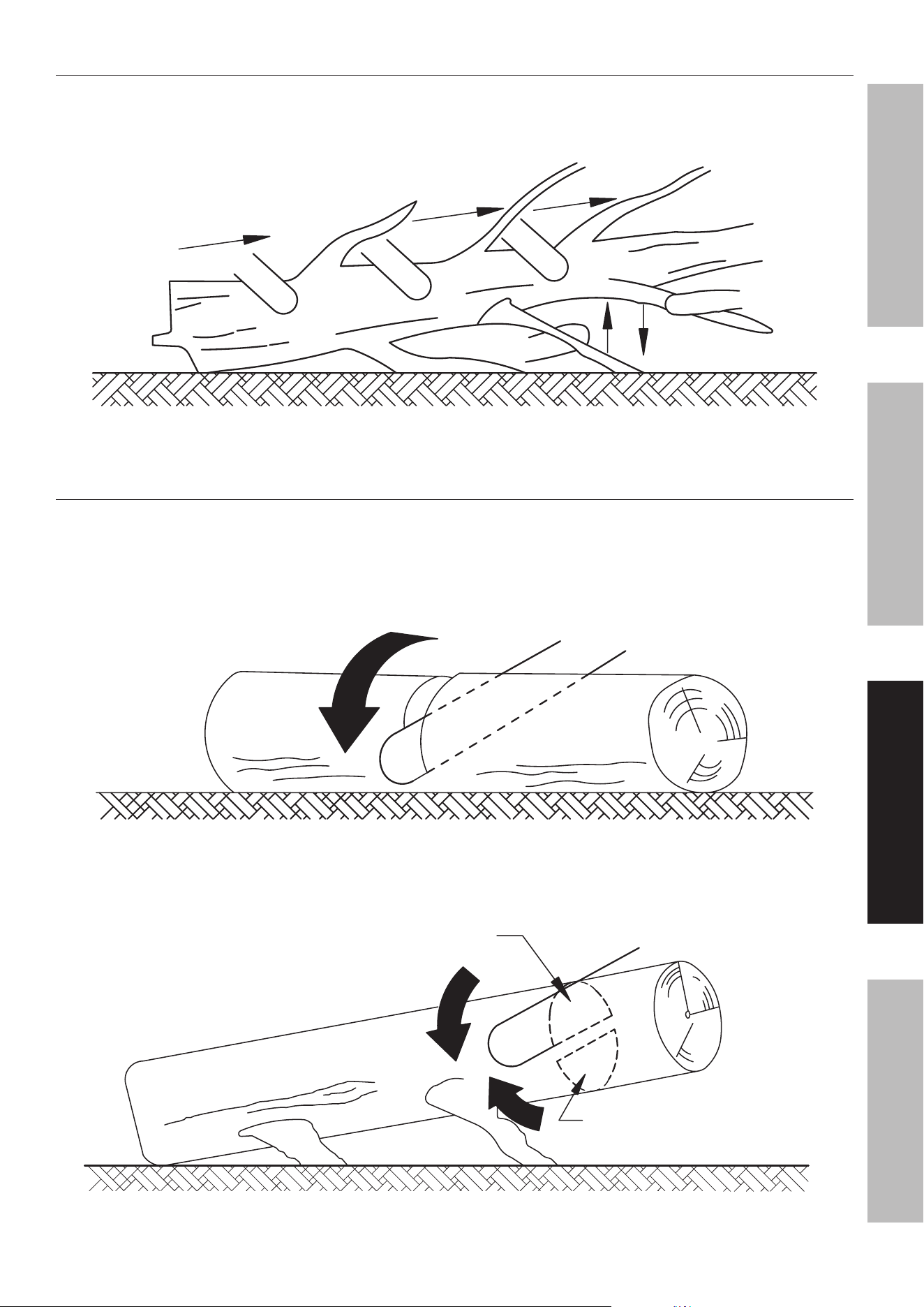
Limbing a Tree
Limbing is removing the branches from a fallen tree. When limbing leave larger lower limbs
to support the log off the ground. Remove the small limbs in one cut as illustrated in Figure K.
Branches under tension should be cut from the bottom up to avoid binding the chainsaw.
Limb Cut
Keep work off ground leave support limbs until log is cut
Figure K: Tree Limbing
Bucking a Log
Bucking is cutting a log into lengths. It is important to make sure your footing is firm and your
weight is evenly distributed on both feet. When possible, the log should be raised and supported
by the use of limbs, logs or chocks. Follow the simple directions for easy cutting.
When the log is supported along its entire length as illustrated in Figure L, it is cut from the top (overbuck).
Cut from top (overbuck) avoid cutting earth
Figure L: Log Supported along the entire Length
When the log is supported on one end, as illustrated in Figure M, cut 1/3 the diameter from the
underside (underbuck). Then make the finished cut by overbucking to meet the first cut.
2
nd
cut overbuck (2/3 diameter)
to meet 1
st
cut (to avoid pinching)
1
st
cut underbuck (1/3 diameter)
to avoid splintering
Figure M: Log Supported One end
Page 18 For technical questions, please call 1-888-866-5797. ITEM 57436
SaFeTy SeTup OperaTiOn MainTenanCe
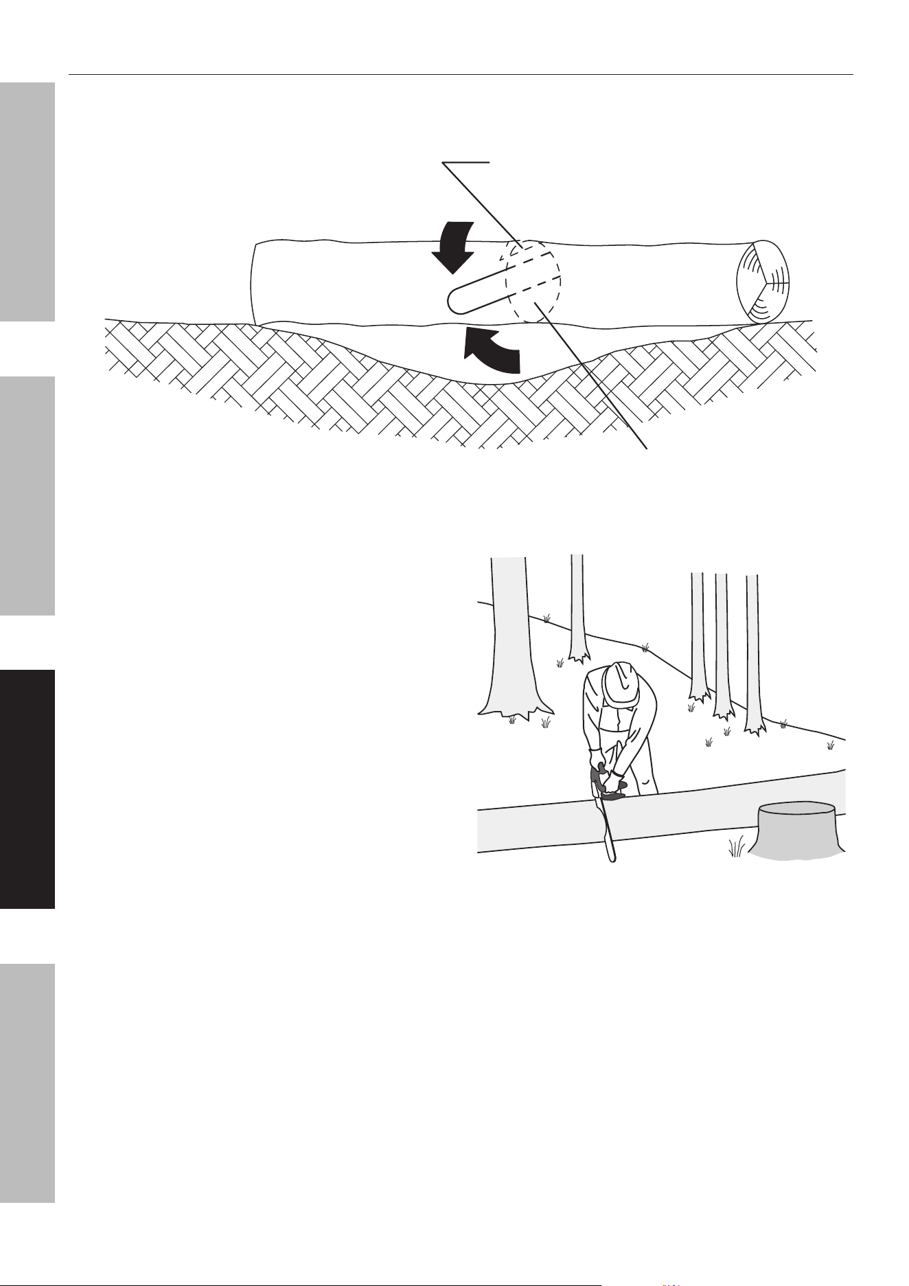
Bucking a Log (continued)
When the log is supported on both ends, as illustrated in Figure N, cut 1/3 the diameter from the top (overbuck).
Then make the finished cut by underbucking the lower 2/3 to meet the first cut.
2
nd
cut underbuck (2/3 diameter)
to meet 1
st
cut (to avoid pinching)
1
st
cut overbuck (1/3 diameter)
to avoid splintering
Figure n: Log Supported Both ends
When bucking on a slope always stand on the
uphill side of the log, as illustrated in Figure O.
When “cutting through”, to maintain complete
control release the cutting pressure near the end of
the cut without relaxing your grip on the chainsaw
handles. Don’t let the chain contact the ground.
After completing the cut, wait for the saw chain to
stop before you move the chainsaw. Always stop
the motor before moving from tree to tree.
Stand on uphill side when cutting
because log may roll
Figure O: Bucking a Log

Page 19For technical questions, please call 1-888-866-5797.ITEM 57436
SaFeTySeTupOperaTiOnMainTenanCe
Maintenance
WarninG
TO preVenT SeriOuS inJury FrOM aCCiDenTaL STarTinG:
Turn the power Switch of the equipment to its “OFF” position, wait for the engine to cool, and disconnect
the spark plug cap before performing any inspection, maintenance, or cleaning procedures.
TO preVenT SeriOuS inJury FrOM eQuipMenT FaiLure:
Do not use damaged equipment. if abnormal noise, vibration, or excess
smoking occurs, have the problem corrected before further use.
Follow all service instructions in this manual. The engine may fail critically if not serviced properly.
Many maintenance procedures, including any not detailed in this manual, will need to be performed
by a qualified technician for safety. if you have any doubts about your ability to safely service the
equipment or engine, have a qualified technician service the equipment instead.
Cleaning, Maintenance, and Lubrication
1. BeFOre eaCH uSe, inspect the general
condition of the tool. Check for:
• loose hardware
• misalignment or binding of moving parts
• cracked or broken parts
• dull or damaged saw chain
• any other condition that may
affect its safe operation.
2. BeFOre FirST uSe anD BeFOre eaCH
uSe THereaFTer, make sure the Oil Tank
is filled with oil (not included). Refer to
Specifications Chart on page 2 for oil type.
3. iF THe SaW CHain BeCOMeS LOOSe, adjust
the Saw Chain tension as described under
Adjusting Saw Chain Tension on page 11.
4. periODiCaLLy Or WHen repLaCinG SaW
CHain, turn the Chain Guide Bar over to distribute
the wear on it. Replace the Guide Bar when bent,
cracked, or when the Saw Chain moves excessively
from side to side on the Guide Bar due to wear.
Refer to Chain Guide Bar Care on page 21.
WarninG! TO preVenT SeriOuS inJury:
replace the Saw Chain and Guide Bar only
with an identical Saw Chain and Guide Bar.
5. aFTer uSe, when the Saw has cooled
completely, clean thoroughly and cover the
Chain Guide Bar with the Chain Guide Bar
Sheath. Do not use solvents. Do not immerse
this tool in liquid. Store the tool indoors out of
children’s reach. See Long-Term Storage on
page 23 for complete storage instructions.

Page 20 For technical questions, please call 1-888-866-5797. ITEM 57436
SaFeTy SeTup OperaTiOn MainTenanCe
Cleaning, Maintenance, and Lubrication Schedule
note: This maintenance schedule is intended solely as a general guide. If performance decreases or if equipment
operates unusually, check systems immediately. The maintenance needs of each piece of equipment will differ
depending on factors such as duty cycle, temperature, air quality, fuel quality, and other factors. If you have
doubts about your ability to safely service this tool, have a qualified technician service the equipment instead.
note: The following procedures are in addition to the regular checks and maintenance
explained as part of the regular operation of the engine and equipment.
procedure
Before
each use
Monthly or
every 10
hr. of use
every 3 mo. or
20 hr. of use
every 6 mo. or
50 hr. of use
yearly or
every 100
hr. of use
every
2 years
Brush off outside of engine
Check engine fuel/oil mixture level
Check air cleaner
Clean air filter
*
Check and clean spark plug
Check/adjust idle speed
1. Clean fuel tank and carburetor
2. Clean carbon build-up from
combustion chamber
** **
Replace fuel line if necessary
**
*Service more frequently when used in dusty areas.
**These items should be serviced by a qualified technician.
periodic Maintenance or When replacing Saw Chain:
a. Clean and lubricate Chain
Guide Bar and turn over.
b. Deburr Guide Bar as needed.
c. Check Chain Sprocket for wear or damage.
Monthly Maintenance:
Clean Chain Oil Tank.
if Worn or Damaged:
a. Replace Chain Guide Bar if it becomes
worn, bent or damaged.
b. Sharpen or replace Saw Chain.
Page 21For technical questions, please call 1-888-866-5797.ITEM 57436
SaFeTySeTupOperaTiOnMainTenanCe
Sharpening/replacing the Saw Chain
CauTiOn! Wear heavy-duty work gloves when handling the Saw Chain.
1. For smooth and safe operation,
always keep the Saw Chain cutters sharp.
2. Have the cutters sharpened by a qualified technician
when you notice any of the following symptoms:
a. The sawdust becomes powder-like.
b. You can’t make the cut without extra force.
c. The Chainsaw does not cut straight.
d. Vibration increases.
3. A Saw Chain that is damaged or too worn to be
restored to a usable condition by sharpening will
need to be replaced. Refer to GuideBar / SawChain
Installation/Replacement on page 10.
WarninG! TO preVenT SeriOuS
inJury: replace the Saw Chain only
with an identical Saw Chain.
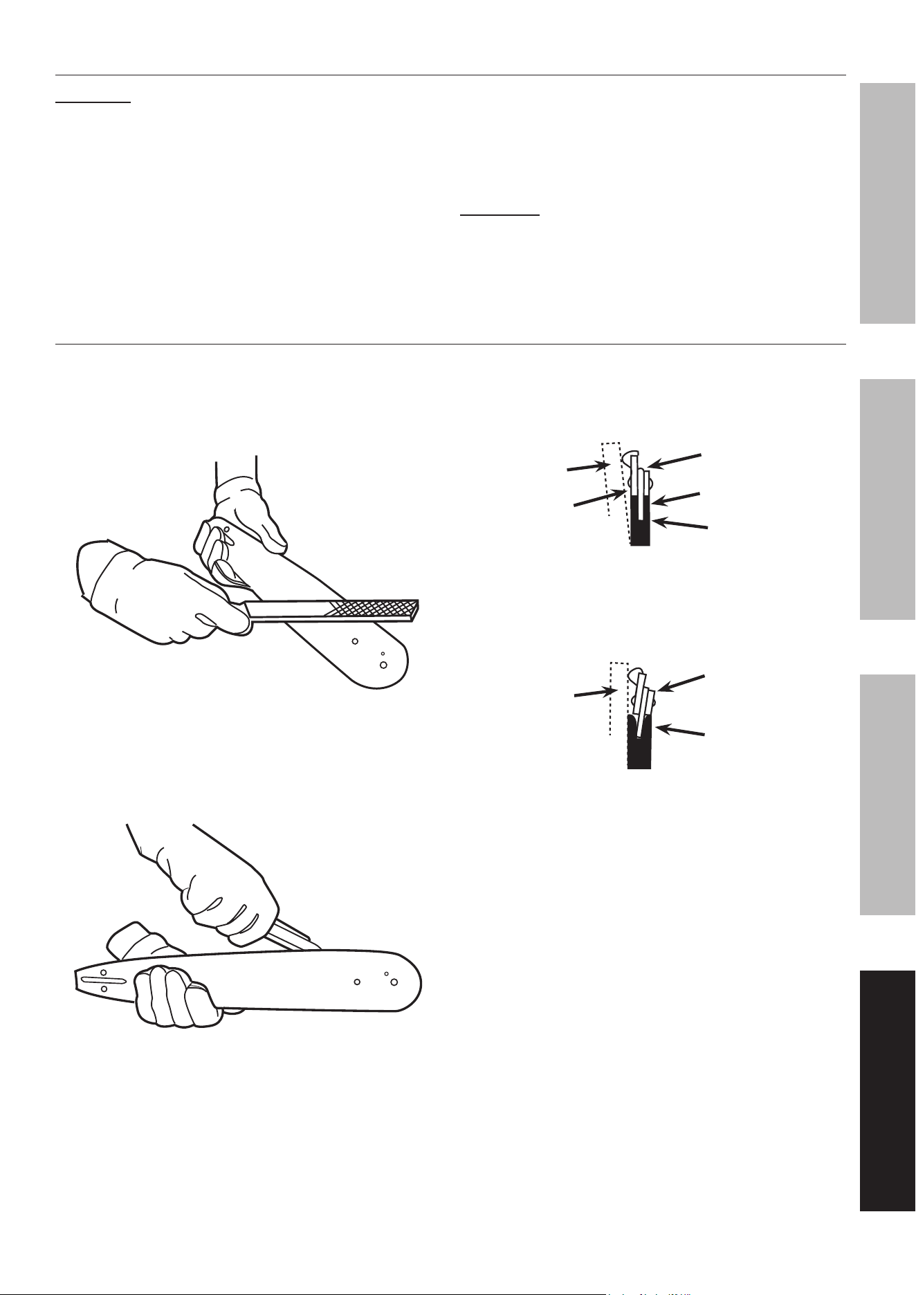
Chain Guide Bar Care
1. Remove the Chain Guide Bar
periodically to clean and lubricate.
2. Deburr rails of Guide Bar as needed.
Use a flat file to make side edges square.
Figure p: Deburring Guide Bar
3. Remove sawdust and sap from the
Bar Groove using a Guide Bar cleaning
tool (sold separately), then lubricate the
nose sprocket at the ports with grease.
Figure Q: Cleaning and Lubricating Guide Bar
4. Reverse the Guide Bar when replacing the
Saw Chain to prevent uneven wear.
5. The rails of the Guide Bar groove should
always be parallel to each other. Place a
ruler along the surface of the Guide Bar and
Saw Chain. If there is a gap, the bar is normal.
Straight
Guide Bar
ruler
rail
Saw
Chain
Gap
Figure r: normal Guide Bar
If the ruler is flush with the Guide Bar and
Saw Chain, or the Chain tilts to one side, then
the Bar is worn and needs to be replaced.
ruler
Worn
Guide Bar
Tilting Saw
Chain
Figure S: Worn Guide Bar
Page 22 For technical questions, please call 1-888-866-5797. ITEM 57436
SaFeTy SeTup OperaTiOn MainTenanCe
Checking and Filling Fuel
WarninG! TO preVenT SeriOuS
inJury FrOM Fire:
Fill the fuel tank in a well-ventilated area
away from ignition sources. If the engine is
hot from use, shut the engine off and wait
for it to cool before adding fuel. Do not smoke.
1. Clean the Fuel Tank Cap and the area around it.
2. Unscrew and remove the Fuel Tank Cap.
note: Do not use gasoline containing more than
10% ethanol (e10). Do not use e85 ethanol. add fuel
stabilizer to the gasoline or the Warranty is VOiD.
note: Do not use gasoline that has been stored in a
metal fuel container or a dirty fuel container. it can
cause particles to enter the carburetor, affecting
engine performance and/or causing damage.
iMpOrTanT: Your Warranty is VOID if the Engine’s
Fuel Tank is not filled with the proper mixture (50:1) of
unleaded gasoline and 2-cycle oil before each use.
2-Stroke oil must meet either JASO M345 FD or ISO-
L-EGD requirements for air-cooled engines, synthetic.
Before each use, check the fuel level. Do not run the
Engine with an improper unleaded gasoline/2-cycle oil
mixture. Running the Engine with an improper
mixture WILL permanently damage the Engine.
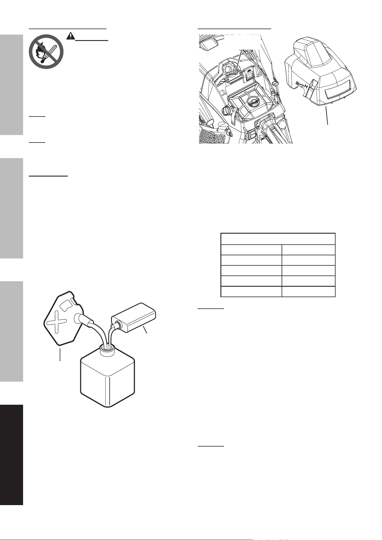
3. To obtain the proper gasoline and 2-cycle oil
mixture, mix 2.6 fluid ounces of 2-cycle oil with
1 gallon of unleaded gasoline into an approved
container. Then gently agitate the container
to thoroughly mix the gasoline/2-cycle oil.
1 GaLLOn
unLeaDeD
GaSOLine
2.6 FLuiD OunCeS
2-CyCLe OiL
apprOVeD
COnTainer
Figure T: Fuel-Oil Mixture
4. If needed, fill the Fuel Tank with the pre-mixed
unleaded gasoline/2-cycle oil mixture. Do not fill
fuel above the bottom of the Fuel Tank fill neck.
5. Then replace the Fuel Tank Cap.
6. Wipe up any spilled fuel and allow excess
to evaporate before starting engine.
To prevent FIRE, do not start the engine
while the smell of fuel hangs in the air.
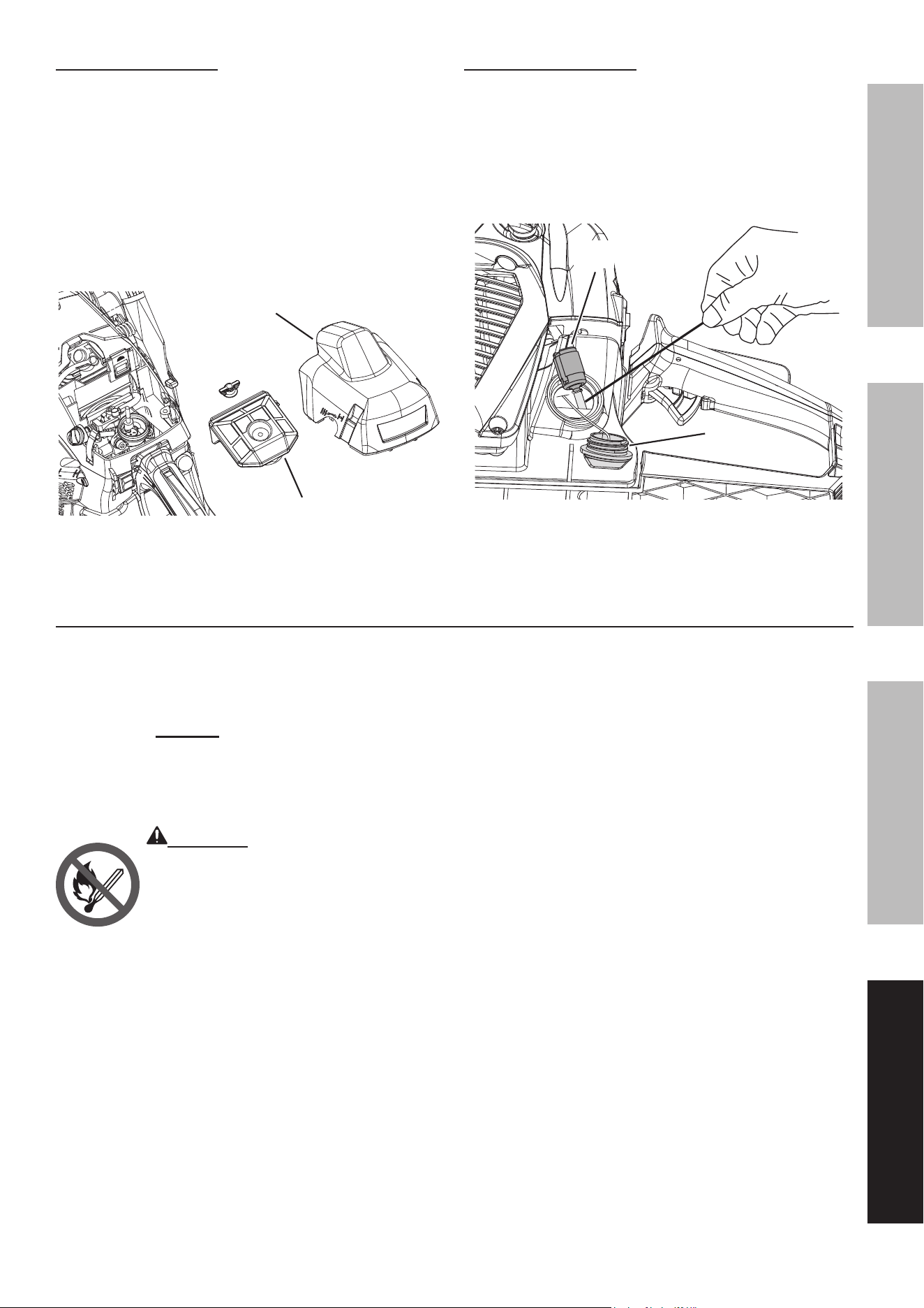
Spark plug Maintenance
Spark plug
Cap
air Filter Cover
1. Remove the Air Filter Cover.
2. Disconnect Spark Plug Cap from end of plug.
Clean out debris from around Spark Plug.
3. Using a spark plug wrench, remove the Spark Plug.
4. Inspect the Spark Plug:
If the electrode is oily, clean it using a clean, dry rag.
If the electrode has deposits on it, polish it using
emery paper. If the white insulator is cracked or
chipped, the spark plug needs to be replaced.
recommended Spark plugs
Champion
®
RCJ7Y
Torch
®
L7RTC
Bosch
®
L8RTF
NGK
®
BPMR7A
DENSO
®
W22MPR
nOTiCe: Using an incorrect spark plug
may damage the engine.
5. When installing a new spark plug,
adjust the plug’s gap to the specification on the
Specifications chart. Do not pry against the
electrode, the spark plug can be damaged.
6. Install the new spark plug or
the cleaned spark plug into the engine.
• Gasket-style:
Finger-tighten until the gasket
contacts the cylinder head,
then tighten about 1/2-2/3 turn more.
• non-gasket-style:
Finger-tighten until the plug
contacts the cylinder head,
then tighten about 1/16 turn more.
nOTiCe: Tighten the Spark Plug properly.
if loose, the Spark Plug will cause the
engine to overheat.
if overtightened, the threads in the
engine block will be damaged.
7. Reattach the Spark Plug Cap securely.
Page 23For technical questions, please call 1-888-866-5797.ITEM 57436
SaFeTySeTupOperaTiOnMainTenanCe
air Filter Maintenance
1. Remove the Air Filter Cover and the Air Filter and
check for dirt. Clean or replace as described below.
2. To prevent injury from dust and debris, wear
ANSI-approved safety goggles, NIOSH-approved
dust mask/respirator, and heavy-duty work
gloves. Remove dust on the Filter surface
by tapping a corner of the Filter against a
hard surface. In a well-ventilated area away
from bystanders, use pressurized air to blow
dust out of the Filter from the inside.
air Filter
air Filter
Cover
3. Install the new or cleaned filter. Reinstall and
secure the Air Filter Cover before use.
Fuel Filter Maintenance
1. Clean the Fuel Tank Cap and the area around it.
2. Remove the Fuel Tank Cap from the Fuel Tank.
3. Use a suction pump (not included) to pump any
fuel in the Tank into a proper gasoline container.
4. Use a piece of wire with a hook on one end to
carefully extract the Fuel Filter from the Tank.
Fuel Fuel
FilterFilter
Fuel
Tank Cap
5. Remove used filter from fuel line. Attach a new
filter to the fuel line and reinsert into the Fuel Tank.
6. Replace Fuel Tank Cap and tighten securely.
Long-Term Storage
When the equipment is to remain idle for longer than
20 days, prepare the Engine for storage as follows:
1. CLeaninG:
Wait for Engine to cool, then clean Engine with
dry cloth. nOTiCe: Do not clean using water.
The water will gradually enter the Engine
and cause rust damage. Apply a thin coat
of rust preventive oil to all metal parts.
2. FueL:
WarninG! TO preVenT SeriOuS
inJury FrOM Fire:
Drain the Fuel Tank in a well-ventilated
area away from ignition sources. If the
Engine is hot from use, shut the Engine off
and wait for it to cool before draining fuel.
Do not smoke.
a. Remove the Fuel Tank Cap and drain any
remaining fuel into an approved storage container.
b. Press the Prime Bulb 10 times.
c. Drain any residual fuel into the storage container.
d. Start the Engine and run at idle until
the Engine stalls from lack of fuel.
e. Replace Fuel Tank Cap and tighten securely.
3. LuBriCaTiOn:
a. Clean out area around spark plug.
Remove spark plug and pour 1/2 tablespoon of
2-stroke oil into cylinder through spark plug hole.
b. Replace spark plug, but leave
spark plug cap disconnected.
c. Pull Starter Handle to distribute oil in cylinder.
Stop after one or two revolutions when you
feel the piston start the compression stroke
(when you start to feel resistance).
d. Remove all residual bar and
chain oil from the Oil Tank.
4. STOraGe area:
Cover and store in a dry, level, well-ventilated
area out of reach of children. Storage area should
also be away from ignition sources, such as
water heaters, clothes dryers, and furnaces.
5. aFTer STOraGe:
Before starting the Engine after storage, follow the
procedures in Pre-Start Checks on page 12.
If using pre-mixed fuel that has been stored, keep
in mind that during storage some of the gasoline
in the fuel evaporates while the 2-stroke oil does
not, altering the gasoline-to-oil mix ratio. Running
the Engine with an improper mixture WILL
permanently damage the Engine. Use freshly
mixed fuel when starting the Engine after storage.

Page 24 For technical questions, please call 1-888-866-5797. ITEM 57436
SaFeTy SeTup OperaTiOn MainTenanCe
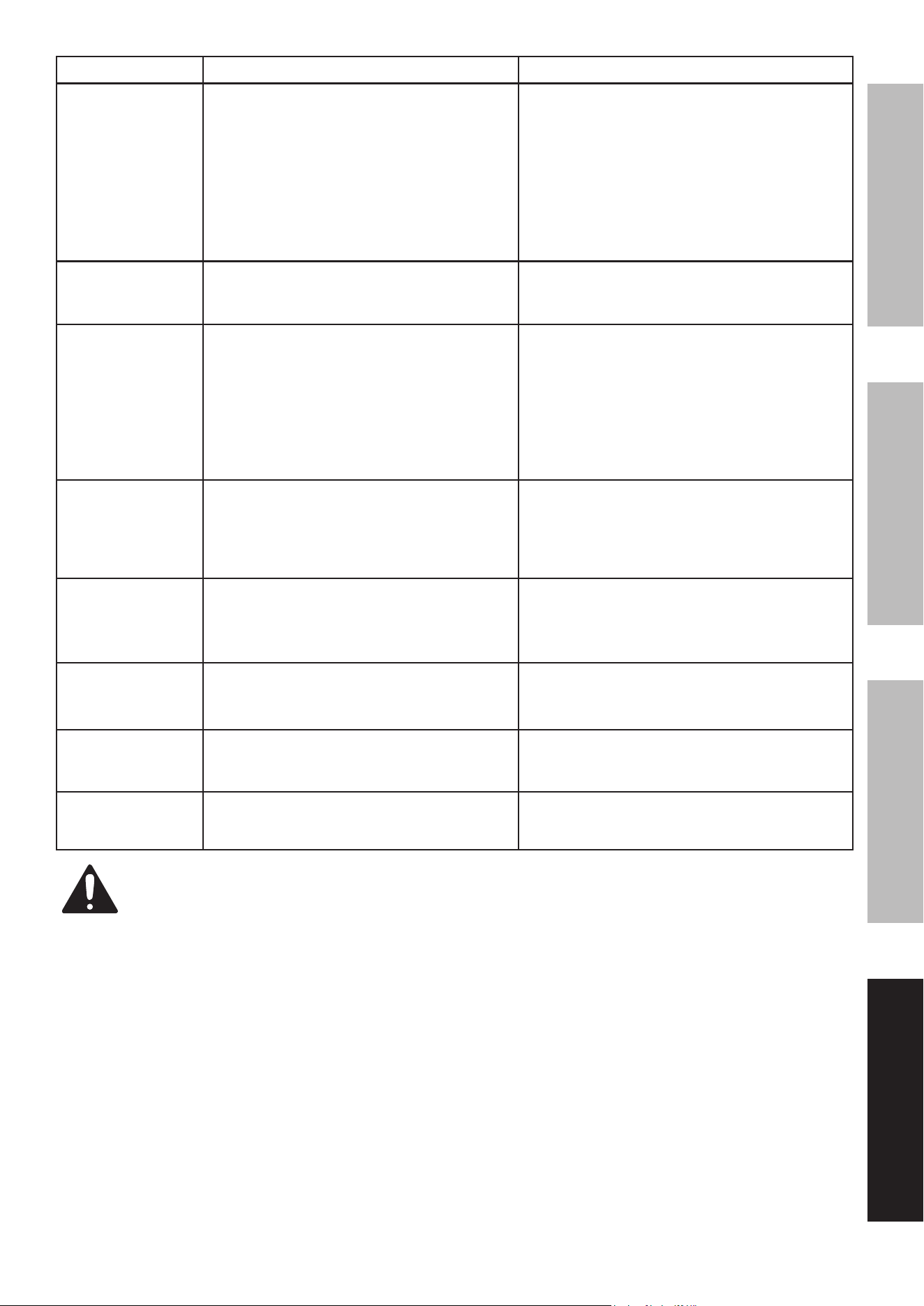
Troubleshooting
problem possible Causes probable Solutions
Engine will not start
FUEL RELATED:
1. No fuel in tank.
2. Choke not in START position, cold engine.
3. Gasoline with more than 10% ethanol
used. (E15, E20, E85, etc.)
4. Low quality or deteriorated, old gasoline/
oil mixture.
5. Carburetor not primed.
6. Dirty fuel passageways.
7. Engine is flooded.
8. Clogged Fuel Filter.
FUEL RELATED:
1. Fill fuel tank with fresh 87+ octane stabilizer-
treated unleaded gasoline/oil mixture only.
Do not use gasoline with more than
10% ethanol (e15, e20, e85, etc.).
2. Move Choke to START position.
3. Clean out ethanol-rich gasoline from fuel
system. Replace components damaged by
ethanol. Use fresh 87+ octane stabilizer-
treated unleaded gasoline/oil mixture only.
Do not use gasoline with more than
10% ethanol (e15, e20, e85, etc.).
4. Use fresh 87+ octane stabilizer-treated
unleaded gasoline/oil mixture.
Do not use gasoline with more than
10% ethanol (e15, e20, e85, etc.).
5. Press the Prime Bulb several times to prime.
6. Clean out passageways using fuel additive.
Heavy deposits may require further cleaning.
7. Remove and clean spark plug. Turn Choke
Knob to RUN position and pull Starter
Handle 10-20 times to clear excess fuel
from cylinder. Replace spark plug and
attempt to start with normal process.
8. Clean or replace Fuel Filter.
IGNITION (SPARK) RELATED:
1. Spark plug cap not connected securely.
2. Spark plug electrode wet or dirty.
3. Incorrect spark plug gap.
4. Spark plug cap broken.
5. Incorrect spark timing or
faulty ignition system.
IGNITION (SPARK) RELATED:
1. Connect spark plug cap properly.
2. Clean spark plug.
3. Correct spark plug gap.
4. Replace spark plug cap.
5. Have qualified technician diagnose/
repair ignition system.
COMPRESSION RELATED:
1. Cylinder not lubricated.
Problem after long storage periods.
2. Loose or broken spark plug.
(Hissing noise will occur
when trying to start.)
COMPRESSION RELATED:
1. Pour 1/2 tablespoon of oil into
spark plug hole. Crank engine a
few times and try to start again.
2. Tighten spark plug.
If that does not work, replace spark plug.
Engine misfires 1. Spark plug cap loose.
2. Incorrect spark plug gap or
damaged spark plug.
3. Defective spark plug cap.
4. Old or low quality gasoline/oil mixture.
5. Incorrect compression.
1. Check cap and wire connections.
2. Re-gap or replace spark plug.
3. Replace spark plug cap.
4. Use only fresh 87+ octane stabilizer-treated
unleaded gasoline/oil mixture.
Do not use gasoline with more than
10% ethanol (e15, e20, e85, etc.).
5. Diagnose and repair compression.
(Use engine will not start:
COMpreSSiOn reLaTeD section.)
Follow all safety precautions whenever diagnosing or servicing the equipment or engine.
Page 25For technical questions, please call 1-888-866-5797.ITEM 57436
SaFeTySeTupOperaTiOnMainTenanCe
problem possible Causes probable Solutions
Engine stops
suddenly
1. Fuel tank empty or full of impure or low
quality gasoline/oil mixture.
2. Defective breather valve creating vacuum,
preventing proper fuel flow.
3. Faulty magneto.
4. Disconnected or improperly
connected spark plug cap.
1. Fill fuel tank with fresh 87+ octane stabilizer-
treated unleaded gasoline/oil mixture.
Do not use gasoline with more than
10% ethanol (e15, e20, e85, etc.).
2. Have qualified technician test/
replace breather valve.
3. Have qualified technician service magneto.
4. Secure spark plug cap.
Engine stops when
under heavy load
1. Dirty air filter
2. Engine running cold.
1. Clean element.
2. Allow engine to warm up prior
to operating equipment.
Engine knocks 1. Old or low quality gasoline/oil mixture.
2. Engine overloaded.
3. Incorrect spark timing, deposit
buildup, worn engine, or other
mechanical problems.
1. Fill fuel tank with fresh 87+ octane stabilizer-
treated unleaded gasoline/oil mixture.
Do not use gasoline with more than
10% ethanol (e15, e20, e85, etc.).
2. Do not exceed equipment’s load rating.
3. Have qualified technician diagnose
and service engine.
After sudden
impact, Engine will
run, but equipment
will not operate
1. Clutch damaged.
2. Shaft key or other shear pin
broken by impact to disconnect
engine and limit damage.
1. Have qualified technician check
and replace damaged clutch.
2. Have qualified technician check and replace
broken shaft key or other shear pins.
Engine runs,
but Chain does
not rotate.
1. Chain tension too tight.
2. Guide Bar and/or Chain damaged.
3. Gear train failure.
1. Adjust Saw Chain tension.
2. Inspect Guide Bar and Chain for damage.
Replace Guide Bar and Chain if necessary.
3. Have qualified technician service tool.
Engine runs, Chain
rotates but does not
cut or cuts poorly.
1. Saw Chain not tensioned properly.
2. Saw Chain dull.
3. Saw Chain installed backwards.
1. Tension Saw Chain properly.
2. Sharpen Saw Chain or replace.
3. Reverse direction of Saw Chain.
Chain comes
off Guide Bar.
1. Chain tension too loose.
2. Guide Bar and Chain not installed correctly.
1. Adjust Saw Chain tension.
2. Review and correct Guide Bar
and Chain installation.
Guide Bar and
Chain running hot
and smoking.
1. Chain tension too tight.
2. Oil Tank empty.
1. Adjust Saw Chain tension.
2. Check/refill Oil Tank.
Follow all safety precautions whenever diagnosing or servicing the equipment or engine.

Page 26 For technical questions, please call 1-888-866-5797. ITEM 57436
SaFeTy SeTup OperaTiOn MainTenanCe
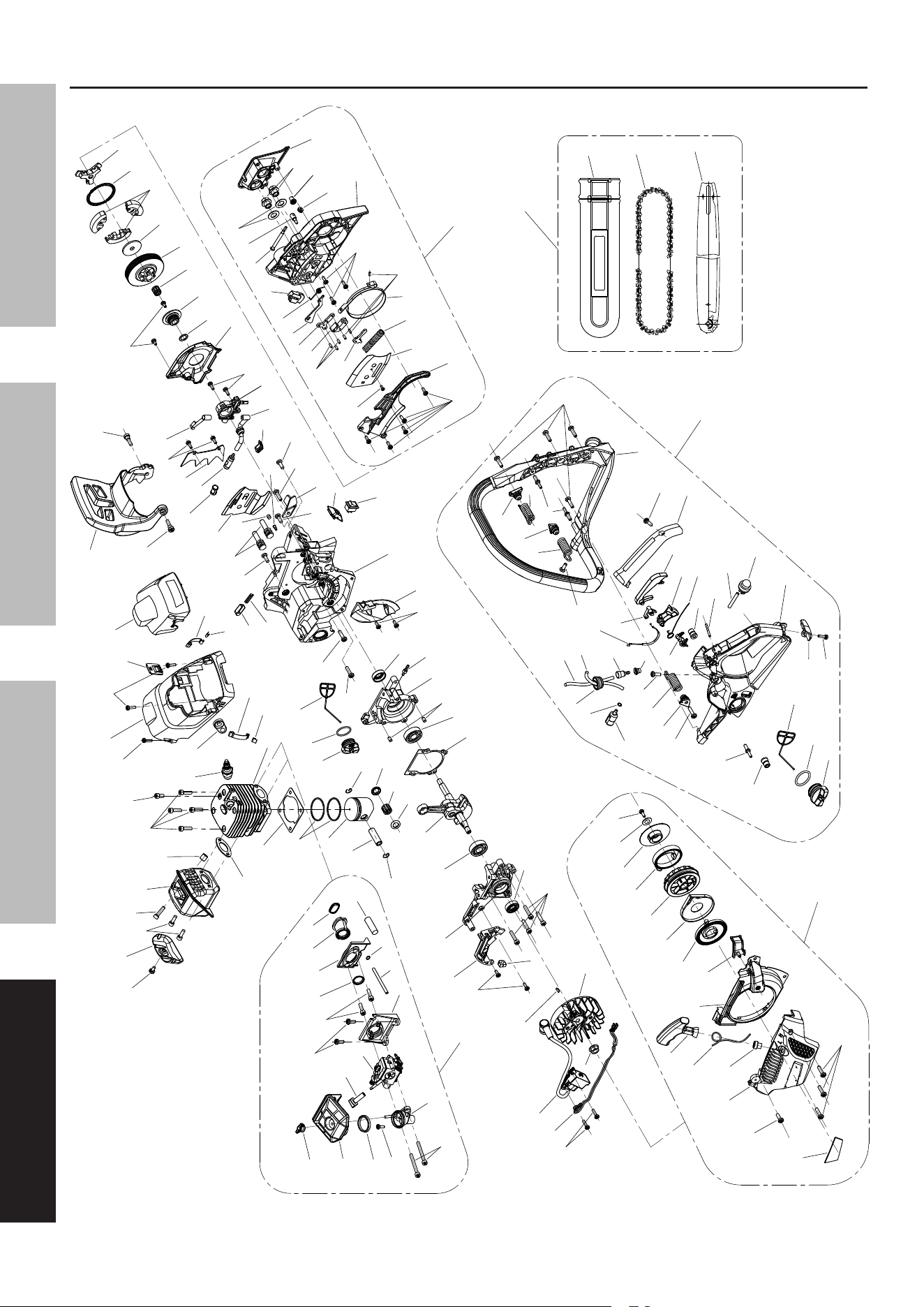
parts List and Diagram
parts List
part Description Qty.
1 Screw M4 x 20 2
2 Extinction Conductor 1
3 Ignition Coil 1
4 Nut M8 x 1 1
5 Flywheel 1
6 Semicircular Key 1
7 Rubber Sleeve 1
8 Tapping Screw St4 x 12 2
9 Screw M5 x 25 4
10 Oil Seal 12 x 22 x 7 1
11 Circuit Board 1
12 Left Crankcase 1
13 Bearing 6201 Grade D 2
14 Crankshaft Assembly 1
15 Piston Pin Clip 2
16 Piston Pin 1
17 Needle Bearing 10 x 14 x 12 1
18 Needle Bearing Ring 2
19 Piston 1
20 Piston Ring 2
21 Cylinder Gasket 1
22 Cylinder 1
23 Screw M5 x 20 4
24 Screw M5 x 10 1
25 Cover Plate 1
26 Screw M5 x 20 2
27 Screw M5 x 20 1
28 Silencer Body 1
29 Support Column 1
30 Silencer Sealing Plate 1
31 Spark Plug 1
32 Plate 2
33 Snap Joint 2
34 Idle Adjusting Guide Set 1
35 Tapping Screw St4 x 16 1
36 Top Housing 1
37 Hot Blast Valve 1
38 Tapping Screw St4 x 22 2
39 Air Filter Cover 1
40 Screw 2
41 Front Damper 1
42 Oil Tank Cap 1
43 Oil Tank Cap Seal 1
44 Oil Tank Cap Retainer 1
45 Reset Device 1
46 Spring 1
47 Case Body Sealing Plate 1
48 Pin Φ5 x 10 2
49 Right Crankcase 1
part Description Qty.
50 Suction Jet 1
51 Oil Seal 12 x 22 x 7 1
52 Tapping Screw St4 x 12 2
53 Sir Deflecor 1
54 Engine Block 1
55 Stop Engine Switch 1
56 Shoe Block 1
57 Chain Retainer 1
58 Tapping Screw St4.8 x 16 1
59 Screw M5 x 14 6
60 Oil Tube 1
61 Oil Pump 1
62 Screw M4 x 12 2
63 Cover Plate 1
64 Turbine Gasket 10 x 18 x 1 1
65 Turbine 1
66 Tapping Screw St4 x 12 2
67 Needle Bearing10 x 13 x 13 1
68 Clutch Shell 1
69 Clutch Adjusting Washer 1
70 Shoe Block 3
71 Clutch Extension Spring 1
72 Retainer 1
73 Bolt M8 x 42 2
74 Aeration Jet 1
75 Sponge Transition Block 1
76 Damper 1
77 Oil Filter 1
78 Spiked Bumper 1
79 Tapping Screw St4.8 x 16 2
80 Nozzle 1
81 Oil Filter Screen 1
82 Rubber Sleeve 1
a Brake Assembly 1
A1 Tapping Screw St4 x 10 5
A2 Brake Spring Cover Plate 1
A3 Screw M4 x 8 1
A4 Tensioner Cover Plate 1
A5 Brake Spring 1
A6 Brake Strap 1
A7 Pin 3 x 9 3
A8 Tapping Screw St4 x 10 3
A9 Brake Control Rod 1
A10 Pin 3.05 x 9 3
A11 Secondary Pull-Rod 1
A12 Main Level 1
A13 Clump Weight Level 1
A14 Clump Weight Spring 1
A15 Clump Weight 1

Page 27For technical questions, please call 1-888-866-5797.ITEM 57436
SaFeTySeTupOperaTiOnMainTenanCe
part Description Qty.
A16 Right Cover Assembly 1
A17 Driven Gear 1
A18 Driving Gear 1
A19 Nut M8 2
A20 Nut Plate 1
A21 Tightener Screw 1
A22 Tension Block 1
A23 Flat Washer 2
B Fuel Tank / Front Handle Assembly 1
B1 Fuel Tank Cap 1
B2 Fuel Tank Cap Seal 1
B3 Fuel Tank Cap Retainer 1
B4 Shock-Reducing Rubber 2
B5 Tapping Screw St5 x 14 3
B6 Tapping Screw St4 x 10 1
B7 Plate 1
B8 Fuel Tank Assembly 1
B9 Tapping Screw St4.8 x 16 1
B10 Damping Spring Socket 3
B11 Damping Spring 3
B12 Tapping Screw St4.8 x 16 2
B13 Fuel Filter 1
B14 Circlip 1
B15 Tubing Ring 1
B16 Oil Tube 2.5 x 5 x 100 1
B17 Oil Tube 2.5 x 5 x 200 1
B18 Balancer Body 1
B19 Balancer Seat 1
B20 Prime Bulb 1
B21 Oil Tube 2.5 x 5 x 60
B22 Pin Φ3 x 25 1
B23 Limit Block 1
B24 Trigger Torsion Rod Spring 1
B25 Trigger 1
B26 Trigger Control Rack 1
B27 Limited Block 1
B28 Cable Accelerator 1
B29 Handle Cover 1
B30 Tapping Screw St4.8 x 12 1
B31 Front Handle 1
B32 Tapping Screw St4.8 x 16 3
part Description Qty.
C Starter Assembly 1
C1 Label 1
C2 Screw M5 x 14 1
C3 Start Cover 1
C4 Eyelet 1
C5 Start Rope 1
C6 Start Grip 1
C7 Bossing 1
C8 Drainage Plate 1
C9 Start Coil Spring 1
C10 Coil Spring Cover 1
C11 Start Plate 1
C12 Easy Start Coil Spring 1
C13 Easy Start Coil Spring Cover 1
C14 Flat Washer Φ5 1
C15 Tapping Screw St4.8 x 13 1
C16 Tapping Screw St4.8 x 16 3
D Air Intake System 1
D1 Tapping Screw St4.8 x 12 1
D2 Rubber Seal 1
D3 Air Filter Assembly 1
D4 Air Filter Knob 1
D5 Screw M5 x 50 2
D6 Air Intake Socket 1
D7 Carburetor 1
D8 Throttle Rod 1
D9 Carburetor Seat 1
D10 Suction Tube 3 x 6.5 x 110 1
D11 Circlip 1
D12 Tapping Screw St4.8 x 12 2
D13 Screw M5 x 20 2
D14 Retaining Coil 1
D15 Plate 1
D16 Air Intake Tube 1
D17 Retaining Coil 1
D18 Drivepipe Φ7 x 90 1
e Cutting System 1
E1 Chain Guide Bar 1
E2 Saw Chain 1
E3 Guide Bar Sheath 1
Page 28 For technical questions, please call 1-888-866-5797. ITEM 57436
SaFeTy SeTup OperaTiOn MainTenanCe
assembly Diagram
C1
C2
C3
C4
C5
C6
C7
C8
C9
C10
C11
C12
C13
C14
C15
1
2
3
4
5
11
7
12
6
9
10
14
16
17
19
21
23
24
25
26
28
30
22
31
35
36
34
39
41
42
43
44
49
50
52
51
53
54
55
56
57
58
60
61
62
63
64
65
66
67
68
69
70
72
45
46
73
75
74
76
77
78
79
80
48
47
D5
D6
D2
D3
D4
D1
D17
D16
D15
D14
D12
D10
D9
D8
D7
A1
A2
A4
A5
A6
A16
A17
A18
A19
A20
A23
A22
A21
A15
A13
A14
A12
A10
A11
A9
A3
A7
A8
B1
B2
B3
B8
B24
B25
B26
B29
B30
B4
B9
B13
B14
B15
B17
B16
B18
B19
B22
B23
B28
B27
B7
B6
B31
B32
D13
8
20
38
37
A
B
C
D
C16
71
D18
81
82
B20
B21
D11
E3
E2
E1
B4
B12
B12
B10
B10
B10
B11
B11
B11
B5
B5
E
13
13
15
15
18
18
27
29
32
33
32
33
40
40
59
59
59
59
59
59

Page 29For technical questions, please call 1-888-866-5797.ITEM 57436
SaFeTySeTupOperaTiOnMainTenanCe
pLeaSe reaD THe FOLLOWinG CareFuLLy
THE MANUFACTURER AND/OR DISTRIBUTOR HAS PROVIDED THE PARTS LIST AND ASSEMBLY DIAGRAM
IN THIS MANUAL AS A REFERENCE TOOL ONLY. NEITHER THE MANUFACTURER OR DISTRIBUTOR
MAKES ANY REPRESENTATION OR WARRANTY OF ANY KIND TO THE BUYER THAT HE OR SHE IS
QUALIFIED TO MAKE ANY REPAIRS TO THE PRODUCT, OR THAT HE OR SHE IS QUALIFIED TO REPLACE
ANY PARTS OF THE PRODUCT. IN FACT, THE MANUFACTURER AND/OR DISTRIBUTOR EXPRESSLY
STATES THAT ALL REPAIRS AND PARTS REPLACEMENTS SHOULD BE UNDERTAKEN BY CERTIFIED AND
LICENSED TECHNICIANS, AND NOT BY THE BUYER. THE BUYER ASSUMES ALL RISK AND LIABILITY
ARISING OUT OF HIS OR HER REPAIRS TO THE ORIGINAL PRODUCT OR REPLACEMENT PARTS
THERETO, OR ARISING OUT OF HIS OR HER INSTALLATION OF REPLACEMENT PARTS THERETO.
record product’s Serial number Here:
note: If product has no serial number, record month and year of purchase instead.
note: Some parts are listed and shown for illustration purposes only, and are not available
individually as replacement parts. Specify UPC 792363574365 when ordering parts.

Page 30 For technical questions, please call 1-888-866-5797. ITEM 57436
SaFeTy SeTup OperaTiOn MainTenanCe
Warranties
Limited 90 Day Warranty (retail)
Harbor Freight Tools Co. makes every effort to assure that its products meet high quality and durability standards,
and warrants to the original purchaser that this product is free from defects in materials and workmanship for the
period of 90 days from the date of purchase. This warranty does not apply to damage due directly or indirectly,
to misuse, abuse, negligence or accidents, repairs or alterations outside our facilities, criminal activity, improper
installation, normal wear and tear, or to lack of maintenance. We shall in no event be liable for death, injuries
to persons or property, or for incidental, contingent, special or consequential damages arising from the use of
our product. Some states do not allow the exclusion or limitation of incidental or consequential damages, so
the above limitation of exclusion may not apply to you. THIS WARRANTY IS EXPRESSLY IN LIEU OF ALL
OTHER WARRANTIES, EXPRESS OR IMPLIED, INCLUDING THE WARRANTIES OF MERCHANTABILITY
AND FITNESS, EXCEPT FOR THE EMISSIONS CONTROL SYSTEM WARRANTY BELOW.
To take advantage of this warranty, the product or part must be returned to us with transportation charges prepaid.
Proof of purchase date and an explanation of the complaint must accompany the merchandise. If our
inspection verifies the defect, we will either repair or replace the product at our election or we may elect to
refund the purchase price if we cannot readily and quickly provide you with a replacement. We will return
repaired products at our expense, but if we determine there is no defect, or that the defect resulted from
causes not within the scope of our warranty, then you must bear the cost of returning the product.
This warranty gives you specific legal rights and you may also have other rights which vary from state to state.

Page 31For technical questions, please call 1-888-866-5797.ITEM 57436
SaFeTySeTupOperaTiOnMainTenanCe
emissions Control System Warranty
Harbor Freight Tools (HFT) is pleased to explain the emissions control system warranty on your Small Off-Road
Engine produced after January 1, [Model Year] (engine), in addition to the Retail Warranty above. HFT warrants
that the emissions control system on your engine is designed, built, and equipped so that it conforms to the United
States Environmental Protections Agency’s (EPA) emissions requirements in effect at the time of manufacture.
HFT also warrants that the emissions control system on your engine will be free from defects in material and
workmanship for two (2) years, provided there has been no improper maintenance, misuse, or abuse of your engine.
Your emissions control system may include parts such as the carburetor or fuel-injection system, and the
ignition system. Also included may be hoses, belts, connectors and other emissions-related assemblies.
WHaT We WiLL DO
Where a warrantable condition exists, HFT will repair or replace, at our option, any emissions-related part on
your engine if it becomes defective, malfunctions, or otherwise fails to conform with this warranty under normal use
and service during the two (2) year term of this warranty at no cost to you, including diagnosis, parts and labor.
This warranty applies to the original purchaser and any subsequent owner within the two year warranty period.
WHaT iS COVereD?
The following parts are examples of components of the emissions control system
and are covered by this two (2) year warranty. For a full list of emissions control
components covered by this warranty, please see 40 CFR §1068, Appendix I.
1. Fuel Metering System
a. Carburetor and its internal parts.
b. Fuel pump (if so equipped).
c. Cold start enrichment system.
2. Air Induction System
a. Intake pipe/manifold.
b. Air cleaner.
3. Ignition System
a. Spark plug.
b. Magneto ignition system.
4. Catalyst System (if so equipped)
a. Exhaust pipe stud.
b. Muffler.
c. Catalytic converter (if so equipped).
5. Miscellaneous Items Used in Above Systems
a. Vacuum, temperature and
time sensitive valves and switches.
b. Hoses, belts, connectors, and assemblies.
This warranty does not cover normal maintenance services or replacement
of maintenance items such as filters, oils, or spark plugs.
WHaT yOu MuST DO TO OBTain WarranTy SerViCe
As the engine owner, you are responsible for the performance of the required maintenance
listed in your Owner’s Manual. HFT may deny you warranty coverage if your engine or a
part has failed due to abuse (including failure to follow the fuel use instructions contained
in this manual), neglect, improper maintenance, or unapproved modifications.
In order to obtain warranty repair or replacement, you may either (a) contact HFT product support at
1-888-866-5797 or [email protected]; or (b) bring the to your nearest Harbor Freight Tools
retail store. When going to the retail store or contacting product support, you must indicate the specific
emissions control part or defect that you are claiming and the date this was originally purchased. The nearest
Harbor Freight Tools retail store can be found on the internet at http://www.harborfreight.com.

26677 agoura road • Calabasas, Ca 91302 • 1-888-866-5797