USE AND INSTALLATION MANUAL
Model:
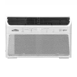
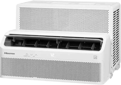
RMV08A10A, Richmond Inverter, 8k
RMV10A10A, Richmond Inverter, 10k
RMV12A10A, Richmond Inverter, 12k
WE ARE HERE TO HELP
For
questions or assistance with features, operation,
performance, parts or service please contact:
CUSTOMER SERVICE
Call: 800-899-1485 (8 a.m. - 5 p.m. CDT) OR
Email: [email protected]

Table of contents
Safety Information ......................................................................................... 3
Important Safety Instructions. ............................................................... 3
Disposing of the Unit. .......................................................................... 3
Pre-Installation .............................................................................................. 7
Electrical requirements. ........................................................................ 7
Recommended Grounding Method. ......................................................7
Wiring requirement. .............................................................................. 8
Power Supply Cord. ............................................................................. 8
Planning Installation. ............................................................................ 9
Hardware Included ............................................................................... 10
Unpack the Air Conditioner ................................................................. 10
Location Requirements. ....................................................................... 12
Window Opening Measurements. ...................................................... 12
If AC is Blocked by Storm Window ................................................... 13
Installation .................................................................................................... 17
Operation ...................................................................................................... 17
Air Conditioner Use. .......................................................................... 19
Using the Remote Control. .................................................................. 22
Changing Air Direction. ..................................................................... 23
Exhaust Air Vent. ................................................................................ 23
Normal Sounds. ................................................................................... 24
Care and Cleaning ....................................................................................... 24
Cleaning the Air Filter ......................................................................... 24
Cleaning the Front Panel. .................................................................... 24
Repairing Paint Damage. .................................................................... 24
Annual Maintenance. .......................................................................... 24
Removing AC From Window ............................................................. 24
Troubleshooting .......................................................................................... 25
Circuit diagram ........................................................................................... 27
03
Safety information
We have provided many important safety messages in this
manual and on your appliance. Always read and obey safety
messages.
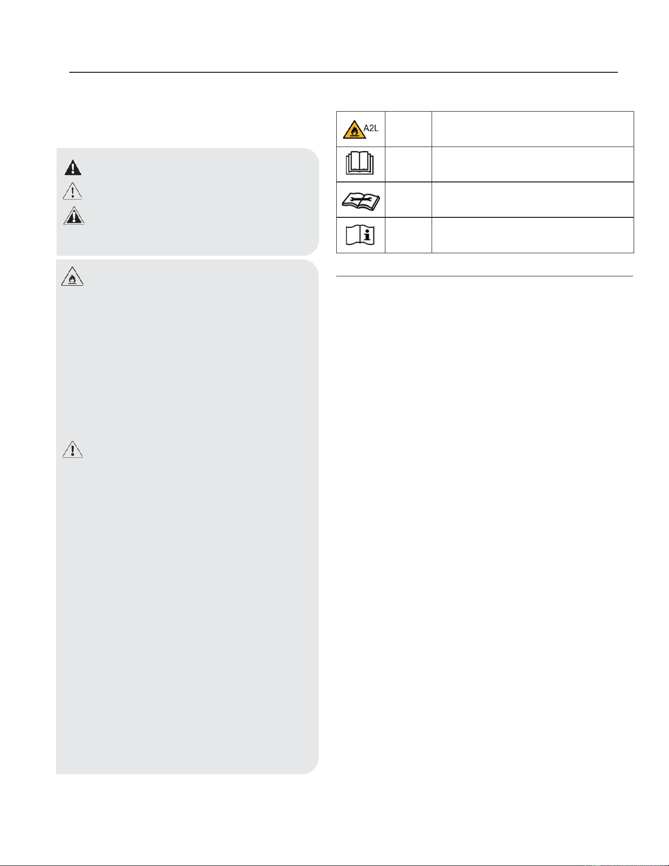
Explanation of symbols displayed on the unit.
WARNING
This symbol shows that this appliance uses a flammable
refrigerant is leaked and exposed to anexternal ignition source,
there is a risk of fire.
CAUTION
This symbol shows that the operation manual should be read
carefully.
CAUTION
This symbol shows that a service personnel should be handling
this equipment with reference to the installation manual.
CAUTION
This symbol shows that information is available such as the
operating manual or installation manual.
Important safety instructions
To reduce the risk of fire, electrical shock or injury when using
your air conditioner, follow these basic precautions:
• Plug into a grounded 3-prong outlet.
• Do not remove ground prong.
• Do not use an adapter.
• Do not use an extension cord.
• Unplug air conditioner before servicing.
• Use two or more people to move and install air condi
tioner.
• If the SUPPLY CORD is damaged, it must be replaced
by the manufacturer, its service agent or similarly
qualified persons in order to avoid a hazard.
Disposing of the unit
• Before throwing out the device, it is necessary to
remove the battery cells and dispose or recycle them
properly.
• When you need disposal of the unit consult our dealer.
If pipes are removed incorrectly, refrigerant may blow
out and come into contact with your skin, causing
injury. Releasing refrigerant into the atmosphere also
damages the environments.
• Please recycle or dispose of the product packaging
material in an environmentally responsible manner.
• Never store or ship the air conditioner upside down or
sideways to avoid damage to the compressor.
• This appliance is not intended for use by persons
(including children) with reduced physical, sensory or
mental capabilities, or lack of experience and knowl
edge, unless they have been given supervision or
instruction concerning use of the appliance by a person
responsible for their safety. Children should be super
vised to ensure that they do not play with the appliance.
• The wiring diagram is shown on nameplate on the air
conditioner.
Danger: This symbol alerts you to a potential hazard,
that if not avoided, will result in death or serious injury.
Warning: This symbol alerts you to a potential hazard,
that if not avoided, could result in death or serious
injury,
Caution: This symbol alerts you to a potential hazard,
that if not avoided, may result in minor or moderate
injury.
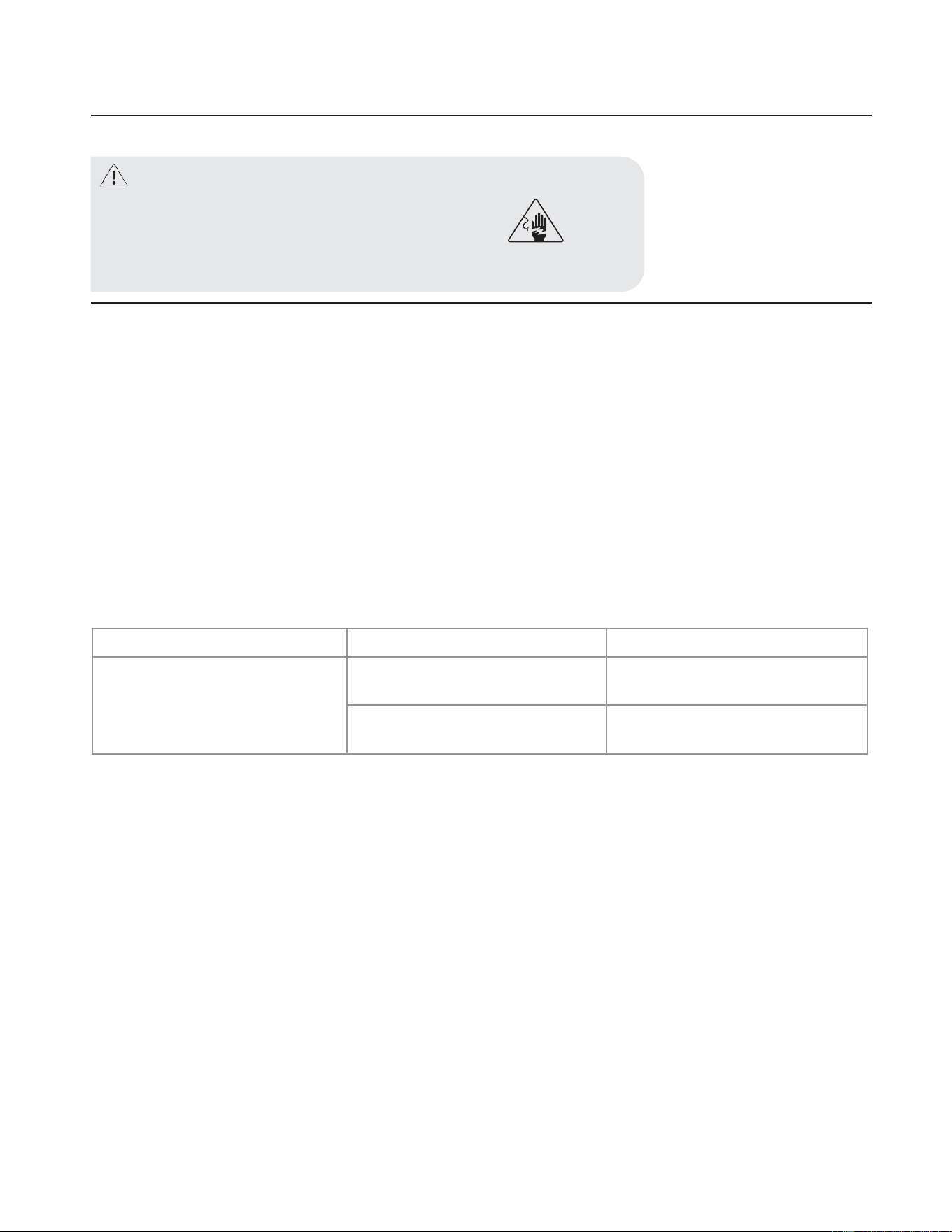
WARNING: Risk of Fire or Explosion. This unit
contains flammable refrigerant.
Additional safety precautions must be followed.
• Do not use means to accelerate the defrosting process
or to clean, other than those recommended by the
manufacturer.
• The appliance shall be stored in a room without
continuously operating ignition sources (for example:
open flames, an operating gas appliance or an
operating electric heater).
• Do not pierce or burn refrigerant tubing. Be aware
that refrigerants may not contain an odor.
• Compliance with national gas regulations shall be
observed.
• Keep ventilation openings clear of obstruction.
• The maximum refrigerant charge amount is shown on
nameplate on the air conditioner.
• When handling, installing, and operating the
appliance, care should be taken to avoid damage to
the refrigerant tubing.
• Do not drill holes in the unit.
• Maintenance, cleaning, and service should only be
performed by technicians properly trained and
qualified in the use of flammable refrigerants.
• Dispose of air conditioner in accordance with Federal
and Local Regulations. Flammable refrigerants
require special disposal procedures. Contact your
local authorities for the environmentally safe disposal
of your air conditioner.
• The appliance shall be stored so as to prevent
mechanical damage from occurring.
• The appliance shall be stored in a well-ventilated area
where the room size corresponds to the room area as
specified for operation.
• This product contains small parts such as (batteries,
battery cover and screws) that may cause suffocation
if swallowed by children.
• For appliances with SUPPLEMENTARY HEATERS,
the minimum clearance from the appliance to
combustible surfaces is 50 cm.
Ji\A2L
w
~
[Il]

04
Precautions for using R32 refrigerant
The basic installation work procedures are the same as the
conventional refrigerant (R22 or R410A).However, pay attention to
the following :
1. Transport of equipment containing flammable refrigerants
Compliance with the transport regulations.
2. Marking of equipment using signs
Compliance with local regulations.
3. Disposal of equipment using flammable refrigerants
Compliance with national regulations.
4. Storage of equipment/appliances
The storage of equipment should be in accordance with the
manufacturer's instructions.
5. Storage of packed (unsold) equipment
Storage package protection should be constructed such that
mechanical damage to the equipment inside the package will not
cause a leak of the refrigerant charge.
The maximum number of pieces of equipment permitted to be
stored together will be determined by local regulations.
6. Information on servicing
Checks to the area: prior to beginning work on systems containing
flammable refrigerants, safety checks are necessary to ensure that
the risk of ignition is minimised. For repair to the refrigerating
system, the following precautions shall be complied with prior to
conducting work on the system.
Work procedure: work shall be undertaken under a controlled
procedure so as to minimise the risk of flammable gas or vapour
being present while the work is being performed.
General work area: all maintenance staff and others working in
the local area shall be instructed on the nature of work being carried
out. Work in confined spaces shall be avoided. The area around the
workspace shall be sectioned off. Ensure that the conditions within
the area have been made safe by control of flammable material.
Checking for presence of refrigerant: the area shall be checked-
with an appropriate refrigerant detector prior to and during work, to
ensure the technician is aware of potentially flammable
atmospheres. Ensure that the leak detection equipment being used
is suitable for use with flammable refrigerants, i.e. non- sparking,
adequately sealed or intrinsically safe.
Presence of fire extinguisher: if any hot work is to be conducted
on the refrigeration equipment or any associated parts, appropriate
fire extinguishing equipment shall be available to hand. Have a dry
powder or CO2 fire extinguisher adjacent to the charging area.
No ignition sources: no person carrying out work in relation to a
refrigeration system which involves exposing any pipe work that
contains or has contained flammable refrigerant shall use any
sources of ignition in such a manner that it may lead to the risk of
fire or explosion. All possible ignition sources, including cigarette
smoking, should be kept sufficiently far away from the site of
installation, repairing, removing and disposal, during which
flammable refrigerant can possibly be released to the surrounding
space. Prior to work taking place, the area around the equipment is
to be surveyed to make sure that there are no flammable hazards or
ignition risks.“No Smoking”signs shall be displayed.
Ventilated area: ensure that the area is in the open or that it is
adequately ventilated before breaking into the system or conducting
any hot work. A degree of ventilation shall continue during the
period that the work is carried out. The ventilation should safely
disperse any released refrigerant and preferably expel it externally
into the atmosphere.
Checks to the refrigeration equipment: where electrical compo-
nents are being changed, they shall be fit for the purpose and to the
correct specification. At all times the manufacturer's maintenance
and service guidelines shall be followed. If in doubt consult the
manufacturer's technical department for assistance. The following
checks shall be applied to installations using flammable refriger-
ants: The charge size is in accordance with the room size within
which the refrigerant containing parts are installed; The ventilation
machinery and outlets are operating adequately and are not
obstructed; If an indirect refrigerating circuit is being used, the
secondary circuit shall be checked for the presence of refrigerant;
Marking to the equipment continues to be visible and legible.
Markings and signs that are illegible shall be corrected; Refrigera-
tion pipe or components are installed in a position where they are
unlikely to be exposed to any substance which may corrode
refrigerant containing components, unless the components are
constructed of materials which are inherently resistant to being
corroded or are suitably protected against being so corroded.
Checks to electrical devices: repair and maintenance to electrical
components shall include initial safety checks and component
inspection procedures. If a fault exists that could compromise
safety, then no electrical supply shall be connected to the circuit
until it is satisfactorily dealt with. If the fault cannot be corrected
immediately but it is necessary to continue operation, an adequate
temporary solution shall be used.
This shall be reported to the owner of the equipment so all parties
are advised. Initial safety checks shall include: That capacitors are
discharged: this shall be done in a safe manner to avoid possibility
of sparking; That there no live electrical components and wiring are
exposed while charging, recovering or purging the system; That
there is continuity of earth bonding.
7. Repairs to sealed components
During repairs to sealed components, all electrical supplies shall be
disconnected from the equipment being worked upon prior
to any removal of sealed covers, etc.
If it is absolutely necessary to have an electrical supply to equip-
ment during servicing, then a permanently operating form of leak
detection shall be located at the most critical point to warn of a
potentially hazardous situation.
Particular attention shall be paid to the following to ensure that by
working on electrical components, the casing is not altered in such
a way that the level of protection is affected.
This shall include damage to cables, excessive number of
connections,terminals not made to original specification, damage to
seals, incorrect fitting of glands, etc.
Ensure that apparatus is mounted securely.
Ensure that seals or sealing materials have not degraded such that
they no longer serve the purpose of preventing the ingress of
flammable atmospheres.

05
Replacement parts shall be in accordance with the manufacturer's
specifications.
8. Repairs to intrinsically safe components
Do not apply any permanent inductive or capacitance loads to the
circuit without ensuring that this will not exceed the permissible
voltage and current permitted for the equipment in use.
Intrinsically safe components are the only types that can be worked
on while live in the presence of a flammable atmosphere. The test
apparatus shall be at the correct rating.
Replace components only with parts specified by the manufacturer.
Other parts may result in the ignition of refrigerant in the
atmosphere from a leak.
9. Cabling
Check that cabling will not be subject to wear, corrosion, excessive
pressure,vibration, sharp edges or any other adverse environmental
effects.
The check shall also take into account the effects of aging or
continual vibration from sources such as compressors or fans.
10. Detection of flammable refrigerants
Under no circumstances shall potential sources of ignition be used
in these arching for or detection of refrigerant leaks.
Ahalide torch (or any other detector using a naked flame) shall not
be used.
11. Leak detection methods
The following leak detection methods are deemed acceptable for
systems containing flammable refrigerants:
–Electronic leak detectors shall be used to detect flammable
refrigerants, but the sensitivity may not be adequate, or may need
re-calibration. (Detection equipment shall be calibrated in a
refrigerant-free area.)
–Ensure that the detector is not a potential source of ignition and is
suitable for the refrigerant used.
–Leak detection equipment shall be set at a percentage of the LFL
of the refrigerant and shall be calibrated to the refrigerant employed
and the appropriate percentage of gas (25 % maximum) is
confirmed.
–Leak detection fluids are suitable for use with most refrigerants
but the use of detergents containing chlorine shall be avoided as the
chlorine may react with the refrigerant and corrode the copper
pipe-work.
–If a leak is suspected, all naked flames shall be removed/
extinguished.
–If a leakage of refrigerant is found which requires brazing, all of
the refrigerant shall be recovered from the system, or isolated (by
means of shutoff valves) in a part of the system remote from the
leak.
–Oxygen free nitrogen (OFN) shall then be purged through the
system both before and during the brazing process.
12. Removal and evacuation
When breaking into the refrigerant circuit to make repairs - or for
any other purpose - conventional procedures shall be used.
However , for flammable refrigerants it is important that best
practice be followed, since flammability is a consideration.
The following procedure shall be adhered to:
a) safely remove refrigerant following local and national
regulations;
b) purge the circuit with inert gas;
c) evacuate ( optional for A2L);
d) purge with inert gas ( optional for A2L);
e) open the circuit by cutting or brazing;
The refrigerant charge shall be recovered into the correct recovery
cylinders if venting is not allowed by local and national codes.
For appliances containing flammable refrigerants, the system shall
be purged with oxygen - free nitrogen to render the appliance safe
for flammable refrigerants. This process might need to be repeated
several times. Compressed air or oxygen shall not be used for
purging refrigerant systems.
For appliances containing flammable refrigerants, refrigerants
purging shall be achieved by breaking the vacuum in the system
with oxygen - free nitrogen and continuing to fill until the working
pressure is achieved, then venting to atmosphere, and finally
pulling down to a vacuum ( optional for A2L). This process shall be
repeated until no refrigerant is within the system ( optional
for A2L). When the final oxygen - free nitrogen charge is used, the
system shall be vented down to atmospheric pressure to enable
work to take place.
Ensure that the outlet for the vacuum pump is not close to any
potential ignition sources and that ventilation is available.
13. Charging procedures
In addition to conventional charging procedures, the following
requirements shall be followed:
–Ensure that contamination of different refrigerants does not occur
when using charging equipment.
–Hoses or lines shall be as short as possible to minimise the amount
of refrigerant contained in them.
–Cylinders shall be kept up right.
–Ensure that the refrigeration system is earthed prior to charging
the system with refrigerant.
–Label the system when charging is complete (if not already).
–Extreme care shall be taken not to overfill the refrigeration
system.
Prior to recharging the system it shall be pressure tested with OFN.
The system shall be leak tested on completion of charging but prior
to commissioning.
A follow up leak test shall be carried out prior to leaving the site.
14. Decommissioning
Before carrying out this procedure, it is essential that the technician
is completely familiar with the equipment and all its detail.
It is recommended good practice that all refrigerants are recovered
safely.
Prior to the task being carried out, an oil and refrigerant sample
shall be taken in case analysis is required prior to re-use of
reclaimed refrigerant. It is essential that electrical power is
available before the task is commenced.
a)
Become familiar with the equipment and its operation.
b)
Isolate system electrically.
c)
Before attempting the procedure ensure that:
–Mechanical handling equipment is available, if required,
Note: The use of silicon sealant may inhibit the effectiveness of some
types of leak detection equipment. Intrinsically safe components do
not have to be isolated prior to working on them.

06
for handling refrigerant cylinders;
–All personal protective equipment is available and being used
correctly;
–The recovery process is supervised at all times by a competent
person;
–Recovery equipment and cylinders conform to the appropriate
standards.
d)
Pump down refrigerant system, if possible.
e)
If a vacuum is not possible, make a manifold so that refrigerant
can be removed from various parts of the system.
f)
Make sure that cylinder is situated on the scales before recovery
takes place.
g)
Start the recovery machine and operate in accordance with
manufacturer's instructions.
h)
Do not overfill cylinders. (No more than 80 % volume liquid
charge).
i)
Do not exceed the maximum working pressure of the cylinder,
even temporarily.
j)
When the cylinders have been filled correctly and the process
completed, make sure that the cylinders and the equipment are
removed from site promptly and all isolation valves on the
equipment are closed off.
k)
Recovered refrigerant shall not be charged into another refrigera-
tion system unless it has been cleaned and checked.
15. Labelling
Equipment shall be labelled stating that it has been de- commis-
sioned and emptied of refrigerant.
The label shall be dated and signed.
Ensure that there are labels on the equipment stating the equipment
contains flammable refrigerant.
16. Recovery
When removing refrigerant from a system, either for servicing or
decommissioning, it is recommended good practice that all
refrigerants are removed safely.
When transferring refrigerant into cylinders, ensure that only
appropriate refrigerant recovery cylinders are employed.
Ensure that the correct number of cylinders for holding the total
system charge is available.
All cylinders to be used are designated for the recovered refrigerant
and labelled for that refrigerant (i.e. special cylinders for the
recovery of refrigerant).
Cylinders shall be complete with pressure relief valve and associat-
ed shut-off valves in good working order.
Empty recovery cylinders are evacuated and, if possible, cooled
before recovery occurs.
The recovery equipment shall be in good working order with a set
of instructions concerning the equipment that is at hand and shall be
suitable for the recovery of flammable refrigerants.
In addition, a set of calibrated weighing scales shall be available
and in good working order.
Hoses shall be complete with leak-free disconnect couplings and in
good condition.
Before using the recovery machine, check that it is in satisfactory
working order, has been properly maintained and that any associat-
ed electrical components are sealed to prevent ignition in the event
of a refrigerant release.
07
Pre-installation
ELECTRICAL REQUIREMENTS
RECOMMENDED GROUNDING METHOD
This air conditioner must be grounded. This air conditioner is equipped with a power supply cord with a three-prong grounding plug. The
cord must be plugged into a three-prong outlet, grounded in accordance with all local codes and ordinances. If a grounded outlet is not
available, it is the customer’s responsibility to have a properly grounded three-prong outlet installed by a qualified electrical installer.
It is the customer’s responsibility:
•
To contact a qualified electrical installer.
•
To assure that the electrical installation is adequate and conforms to the Nation Electrical Code, ANSI/NFPA 70-last edition, and
all local codes and ordinances.
•
Copies of the standards listed may be obtained from: National Fire Protection Association
1 Batterymarch Park
Quincy, Ma 02169-7471 www.nfpa.org
WIRING REQUIREMENT
Power supply
Model
Time-delay fuse (or circuitbreaker)
115V
103.5V min
126.5V max
8K BTU cooling only
10K BTU cooling only
13A
12K BTU cooling only
14K BTU cooling only
15A
WARNING: Electrical shock hazard
-Plug into grounded 3-prong outlet.
-Do not remove ground prong.
-Do not use an adapter.
-Do not use an extension cord.
-Failure to follor these instructions can result in death, fire or electrical shock.
08
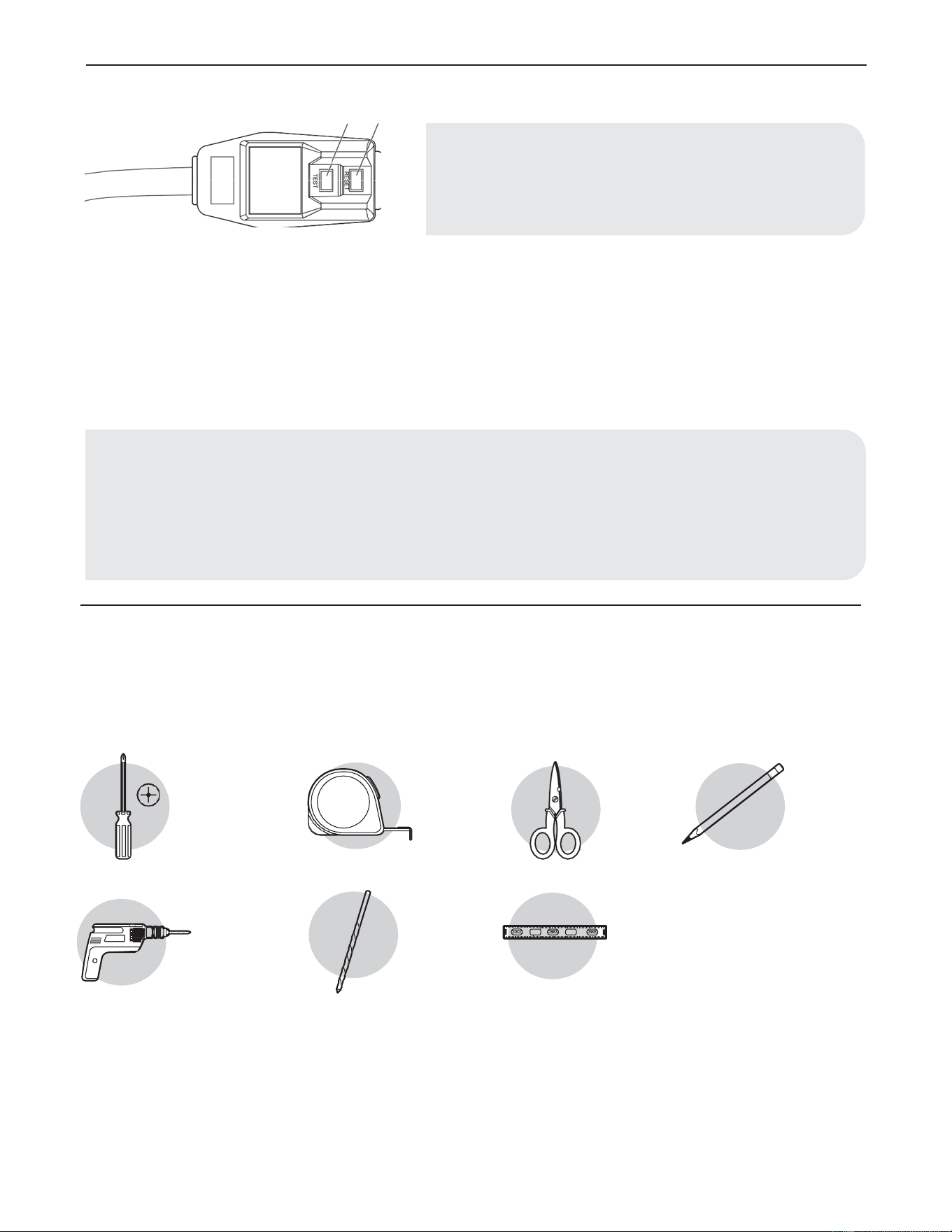
POWER SUPPLY CORD
To test your power supply cord:
1. Plug power supply cord into a grounded 3-prong outlet.
2. Press RESET (2) (on some devices, a green light will turn on).
3. Press TEST (1) and listen for click. The RESET button will trip and on some devices, a green light will turn off.
4. Press and release RESET (2) and listen for click. The RESET button will latch, and on some devices, a green light will turn on. The
power supply cord is ready for operation.
PLANNING INSTALLATION
Gather the required tools and parts before starting installation. Read and follow the instructions provided with any tools listed here.
TOOLS REQUIRED
Philips
screwdriver
Cordless drill
Tape
measure
1/8 in. bit
Scissors
Level
Pencil
NOTE: Your air conditioner’s device may differ from the one shown.
This room air conditioner is equipped with a power supply cord required
by UL. This power supply cord contains state-of-the-art electronics that
sense leakage current. If the cord is crushed, the electronics detect leakage
current and power will be disconnected in a fraction of a second.
NOTE:
• The power supply cord must be replaced if it fails to trip when the test button is pressed or fails to reset.
• Do not use the power supply cord as an off/on switch. The power supply cord is designed as a protective device.
• A damaged power supply cord must be replaced with a new power supply cord obtained from the product manufacturer and must
not be repaired.
• The power supply cord contains no user serviceable parts. Opening the tamper-resistant case voids all warranty and performance
claims.
09
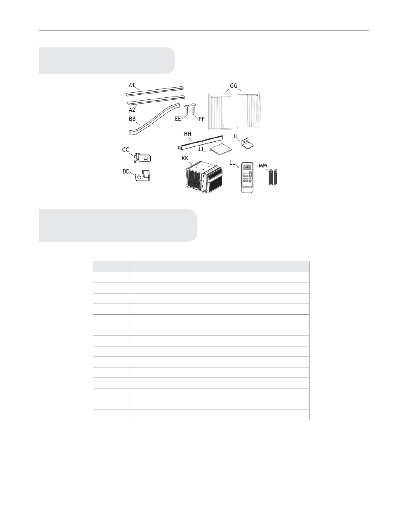
HARDWARE INCLUDED
Part
Description
Quantity
A1
Adhesive seal (gray)
1
A2
Adhesive seal (black)
1
BB
Foam seal
1
CC
Lock frame (for wooden windows)
2
DD
Lock frame (for vinyl-clad windows)
2
EE
3/8 inch screws
4
FF
3/4 inch screws
7
GG
Side curtains
2
HH
Top rail
1
II
Sash lock
1
JJ
EVA foam
2
KK
Air conditioner
1
LL
Remote control
1
MM
Batteries (standard AAA 1.5 Volt)
2
NOTE:
Check that all parts are included in parts package.
NOTE:
For 12/14K Btu models, top rail(HH) and 3/8 inch screws(EE)
had been attached by manufacturer.
10
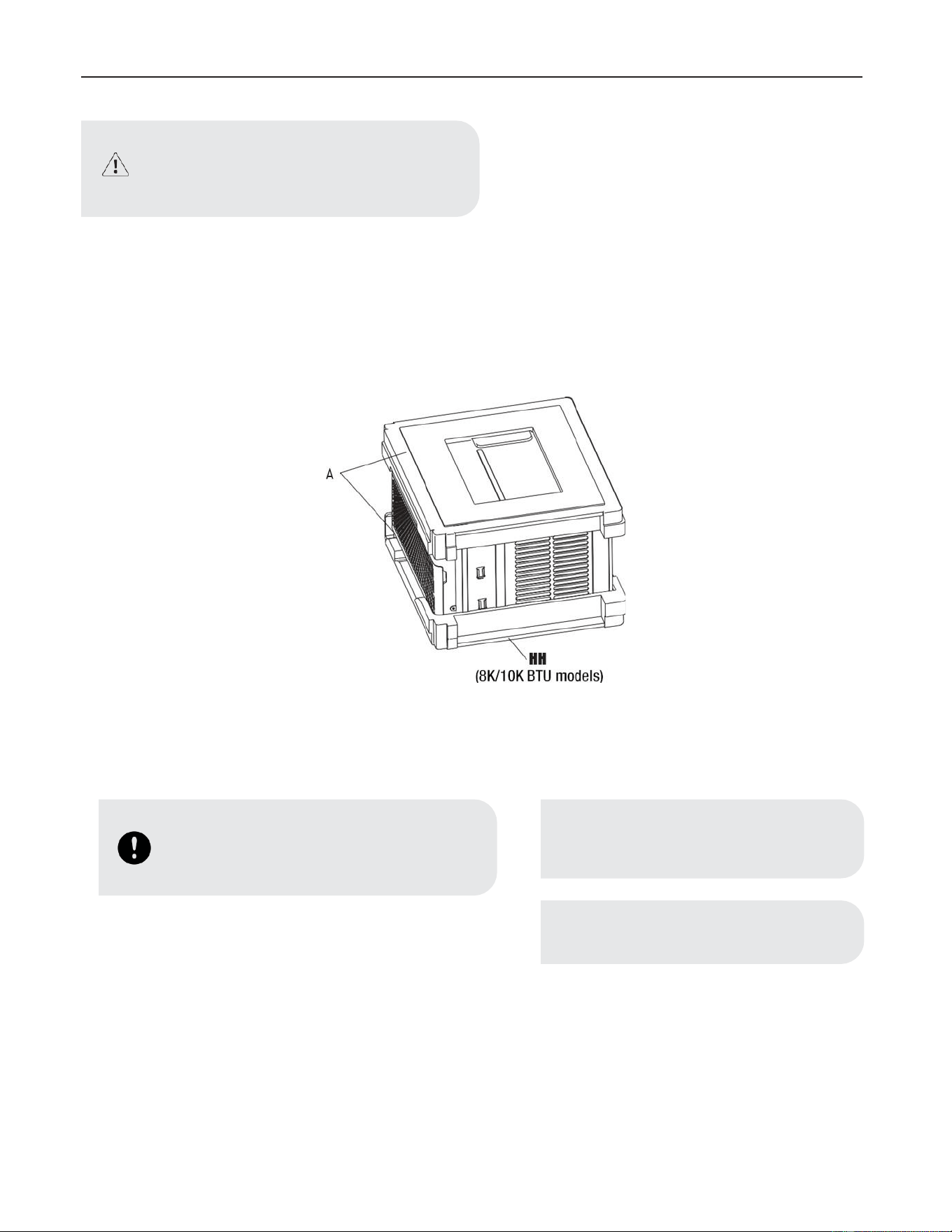
UNPACK THE AIR CONDITIONER
Remove packaging materials
• Remove and dispose of/recycle packaging materials. Remove tape and glue residue from surfaces before turning on the air conditioner.
Rub a small amount of liquid dish soap over the adhesive with your fingers. Wipe with warm water and dry.
• Do not use sharp instruments, rubbing alcohol, flammable fluids, or abrasive cleaners to remove tape or glue. These products can
damage the surface of your air conditioner.
• Handle the air conditioner gently.
• Remove top rail (HH) from the packaging material (A).
LOCATION REQUIREMENTS
Before you Begin
Read these instructions completely and carefully.
• Skill level: Installation of this appliance requires basic mechanical skills.
• Completion time: Approximately 1 hour.
• We recommend that two people install this product.
WARNING:
Excessuve weight hazard. Use two or more people to
move and install air conditioner. Failure to do so can
result in back or other injury.
IMPORTANT:
• Save these instructions for local inspector’s use.
• Observe all governing codes and ordinances.
NOTE:
• Save these instructions for local inspector´s use.
• Observe all governing codes and ordinances.
NOTE:
Consumer, keep these instructions for future reference.
A
NH
(8K/1
OK
BTU
models)
8
11
• Proper installation is the responsibility of the installer.
• Product failure due to improper installation is not covered under the warranty.
• You MUST use all supplied parts and use proper installation procedures as described in these instructions when installing this air
conditioner.
Check the location where air conditioner will be installed. Proper installation is your responsibility. Make sure you have everything
necessary for correct installation.
The location should provide:
• Do not use an extension cord. The appliance shall be installed in accordance with national wiring regulations.
• Free movement of air in room to be cooled.
• A large enough opening for the air conditioner.
IMPORTANT:
Observe all governing codes and ordinances.
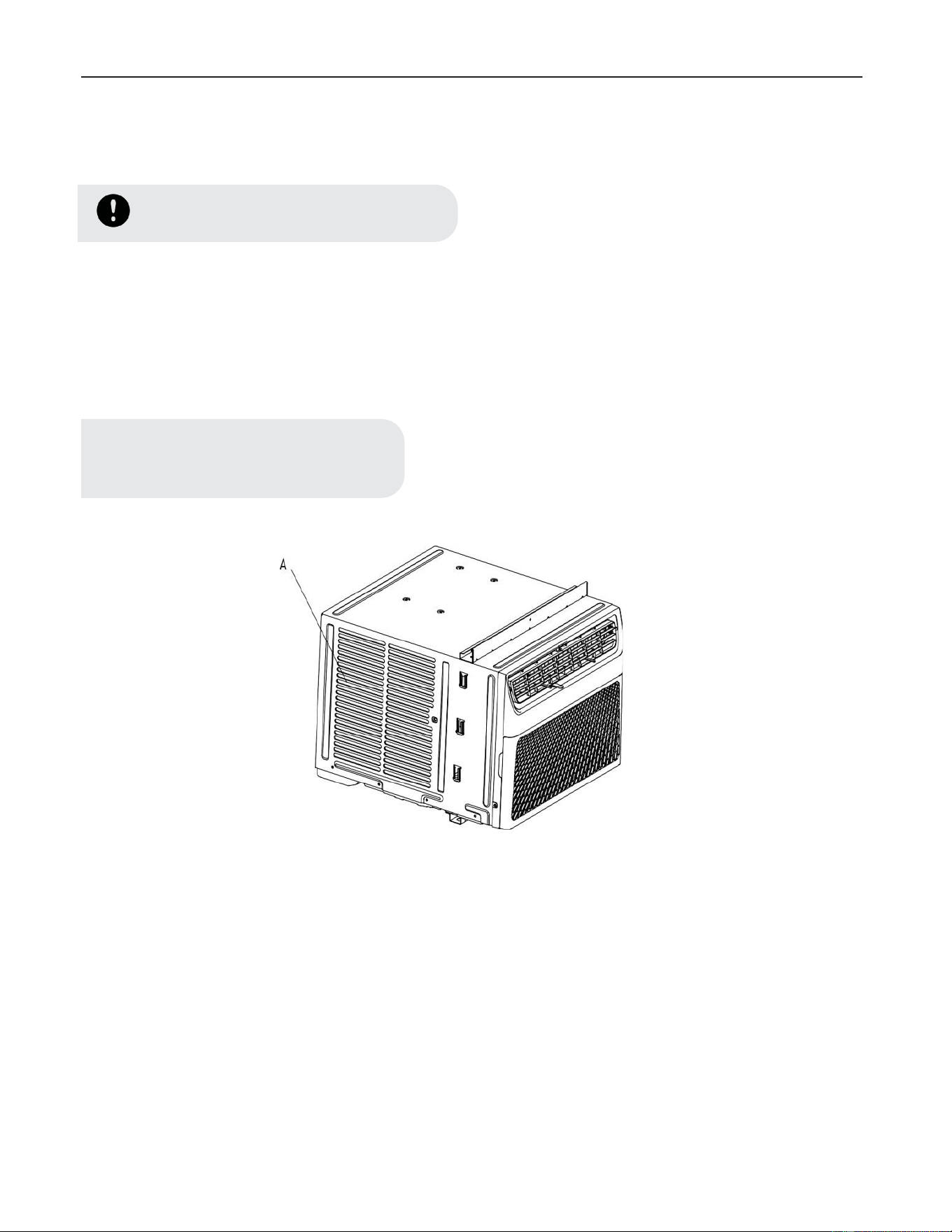
NOTE:
Cabinet louvers (A) must not be obstructed. Air must
be able to pass freely through the cabinet louvers.
0
A
12
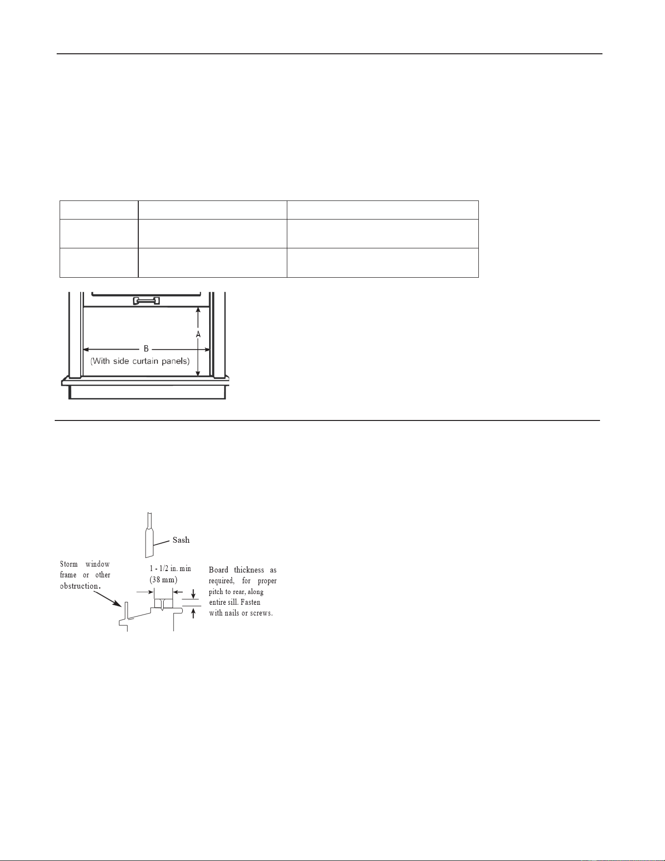
WINDOW OPENING MEASUREMENTS
• These instructions are for a standard double-hung window. You will need to modify them for other types of windows.
• The air conditioner can be installed without the side curtain panels if needed to fit in a narrow window. See the window opening
dimensions.
• All supporting parts must be secured to firm wood, masonry or metal.
• The electrical outlet must be within reach of the power cord.
• Follow the dimensions in the table and illustration for your model.
Models
A
B
8K BTU
10K BTU
13 3/5 inch (345 mm) min
24 1/2 inch (622 mm) - 39 inch (991 mm)
12K BTU
14K BTU
15 1/5 inch (386 mm) min
24 9/10 inch (632 mm) - 39 inch (991 mm)
IF AC IS BLOCKED BY STORM WINDOW
Add wood as shown, or remove storm window before air conditioner is installed.
If storm window frame must remain, be sure the drain holes or slots are not caulked or painted shut. Accumulated rain water or condensation
must be allowed to drain out.
.
~
-
B
(With side
cu
rt
ain panel
s)
Storm
wi
ndow
fra
me
or
ot
he
r
~Sas
h
i
A
I •
112
in.
m
in
(38
m
m)
obs
""
otio~
~
Board thickness
as
r
equired
,
for
p
ro
p
er
p
itc
h to
rear
, al
ong
entire
si
ll
.
Fas
t
en
with
na
il
s
or
screws.
13
Installation
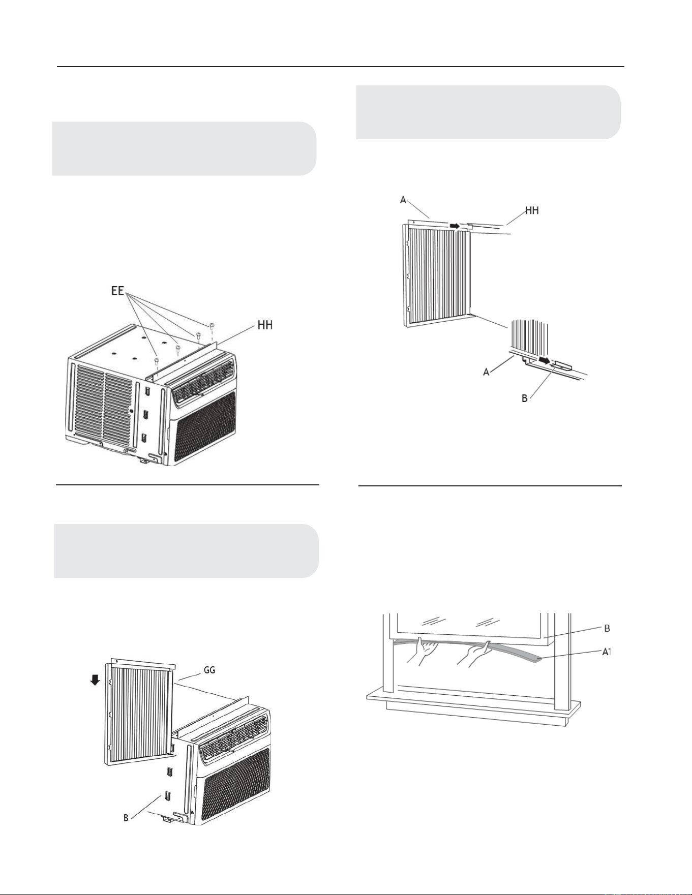
1 Attaching the Top Rail
• Locate the bag of screws provided.
• Place the top rail (HH) on top of the air condition-
er cabinet, lining up the 4 holes in the top rail with
the 4 holes on top of the air conditioner cabinet.
• Using four 3/8 inch (10 mm) screws (EE), attach
the top rail (HH) to the air conditioner cabinet.
2. Installing the Side Curtains
• Slide the side curtain (GG) directly into the
cabinet (B).
• Slide the side curtain (GG) down.
• Insert top and then bottom of left-hand curtain
housing(A) in top rail (HH) and bottom rails (B) on
air conditioner.
• Slide the curtain housing into the rails as far as it will
go.
• Repeat above steps for the right-hand curtain.
3. Attaching the Adhesive Seal
• Cut the adhesive seal (gray) (A1) to the width of the
lower window sash (B).
• Remove the backing from the seal and attach the seal
to the bottom of the lower window sash.
NOTE:
Attach curtains to the air conditioner before placing the
air conditioner in window.
NOTE:
For certain models, top rail has been attached by
manufacturer.
NOTE:
Attach side curtains to the air conditioner before
placing the air conditioner in window.
14
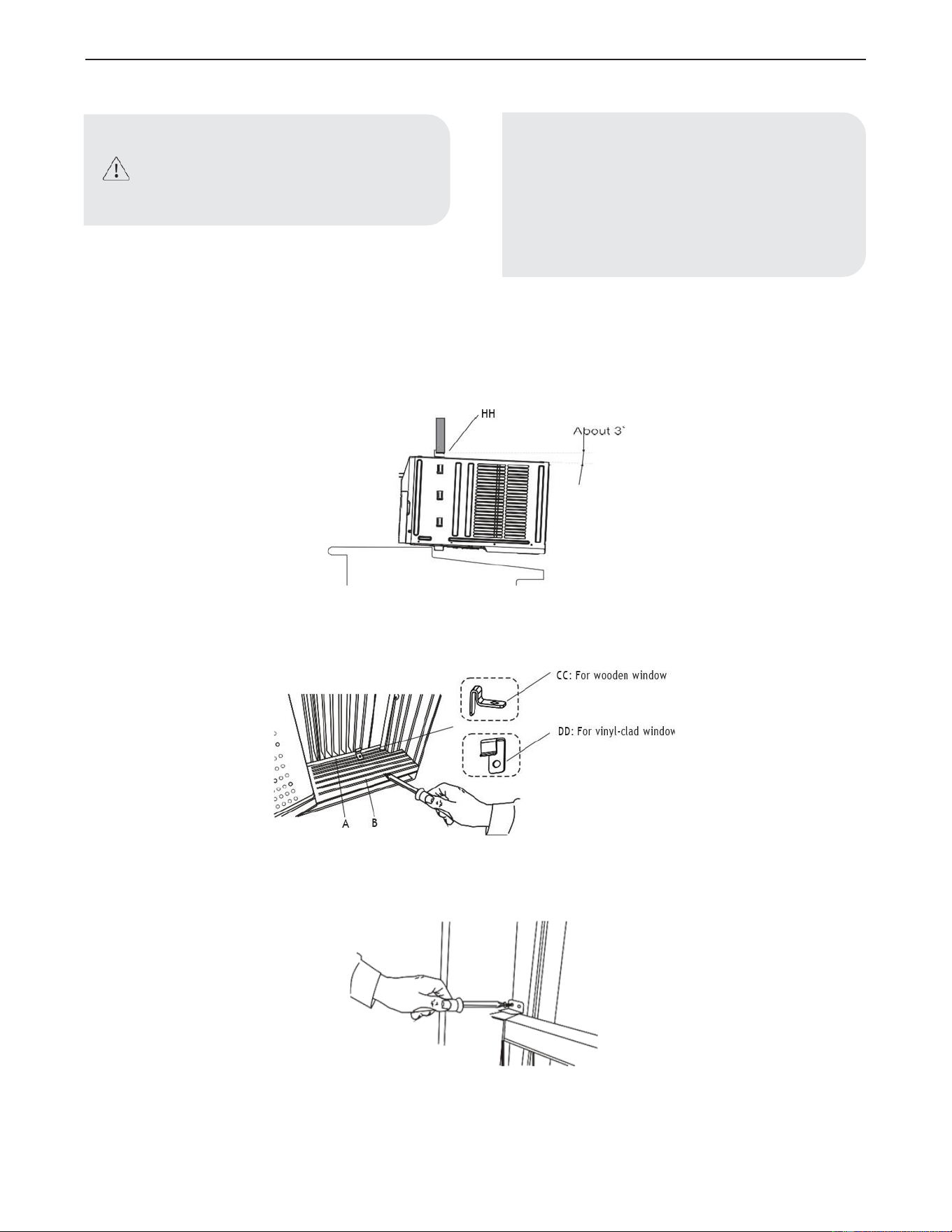
4. Placing Air Conditioner in Window
• Center air conditioner in window. Lower the window sash behind the top rail (HH) to hold cabinet in place.
• Keeping a firm grip on the air conditioner, carefully place the unit into the window opening so the bottom of the air conditioner frame
is against the window sill and make sure the unit is staying center of the window.
• Carefully close the window behind the top rail of the unit.
• Place the frame lock (CC) or (DD) between the curtain housing (A) and the window sill (B) with 3/4 inch (19 mm)screw (FF) as
shown.
• To secure lower sash in place, attach sash lock (II) with 3/4 inch (19 mm) screw (FF) as shown.
WARNING:
Excessive Weight Hazard
Use two or more people to move and install air
conditioner.
Failure to do so can result in back or other injury.
NOTE:
• Handle air conditioner gently.
• Be sure your air conditioner does not fall out of
the opening during installation or removal.
• Do not block the louvers in the front panel.
• Do not block the louvers on the outside of the air
conditioner.
• Your model may differ from the one shown.
(------
y
CC'
,
~
, • F
or
wooden
w·
d
1
In
OW
I I
' I
______
.,,..,
r-
~
---
y
',
DD:
For
vinyl-clad
• d
I
wm
OW
',
0 :
______
..,,
15
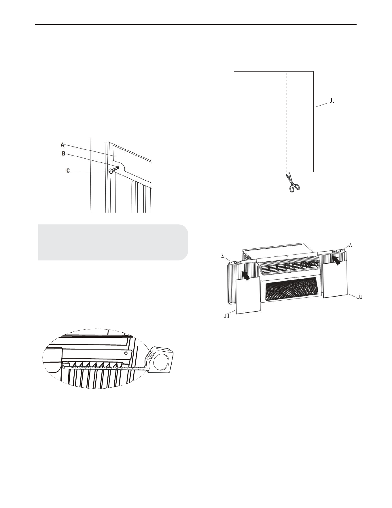
5. Attaching Side Curtains to Window
• Pull the left-hand side curtain out until it fits into
the window channel.
• Use a 1/8 inch (3 mm) drill bit to drill a starter
hole through the hole in the curtain housing (B) .
• Insert one of the 3/4 inch (19 mm) screws (C)
through the left-hand curtain housing (B) and into
the window sash (A).
• Repeat for the right-hand curtain.
• Put one EVA foam (JJ) on the curtain housing.
• In order to minimize air leaks and ensure optimal
insulation, it is necessary to install the EVA Foam
(JJ) on the curtain housing.
• After the unit is installed to the window, measure
the inner width of the side curtain as shown.
• Remark a line on the EVA foam (JJ) according to
less 1 /8 inch (3 mm) than the measured width,
then cut the EVA foam (JJ) along the line.
• Remove the backing from the EVA foam (JJ).
Attach one EVA foam (JJ) on the curtain housing
(A), the side with adhesive should facing the
curtain housing.
• Repeat for the left-hand curtain.
NOTE:
The remaining steps on this page are only applicable
for E-star models,with E-star LOGO on the control
panel.
A
B
Jj
i....------'
----
JJ
16
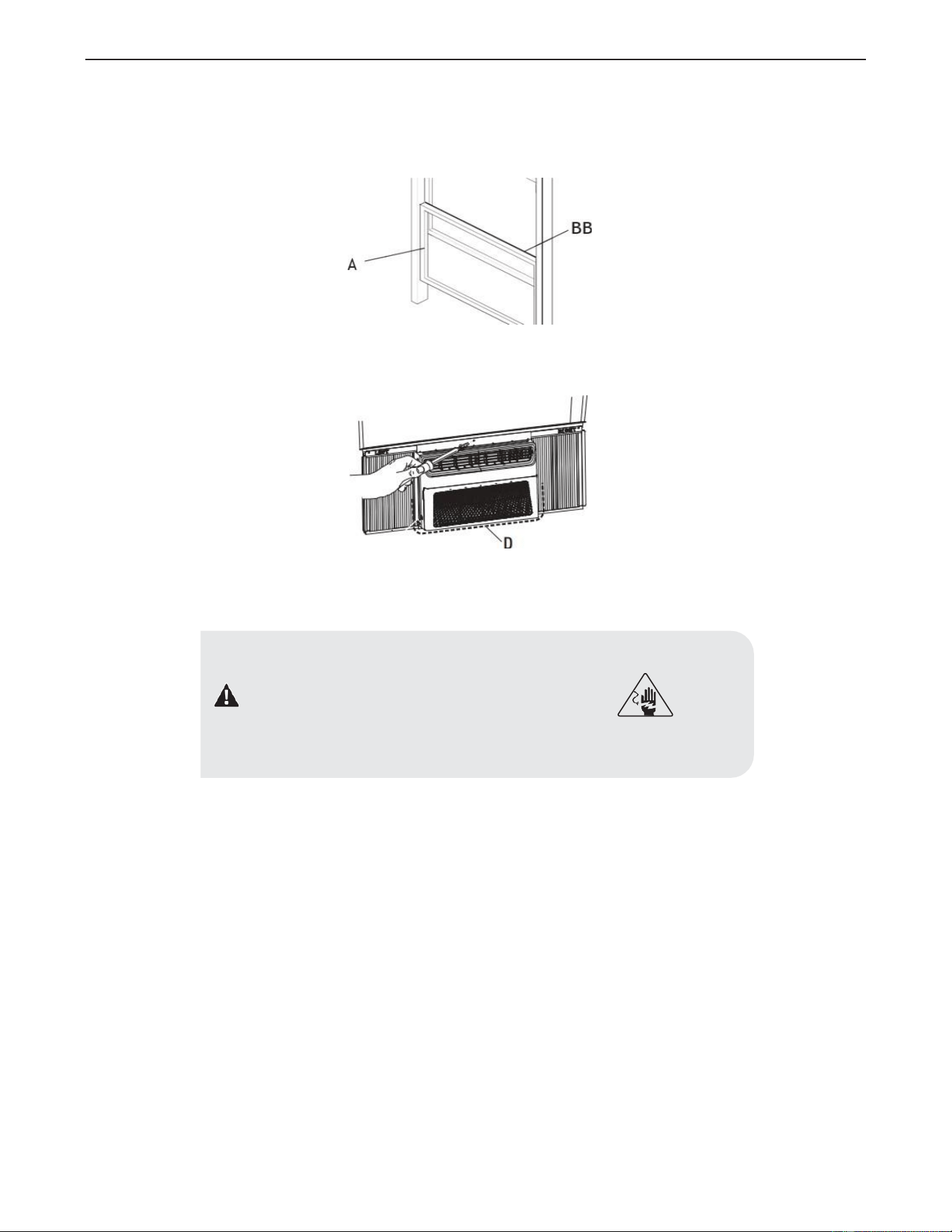
6. Completing Installation
• Insert foam seal (BB) behind the top of the lower window sash (A) and against the glass of the upper window.
• Use a 1 /8 inch (3 mm) drill bit to drill a starter hole through the hole in the top rail.
• Attach top rail to window sash with one 3/4 inch (19 mm)screw to secure window in place.
• Check the gap (D) around the unit and seal it with the adhesive seal (black) (A2) attached.
• Plug into a grounded 3-prong outlet.
• Press RESET on the power supply cord. See “Electrical Requirements”.
DANGER: ELECTRICAL SHOCK HAZARD
• Plug into a grounded 3-prong outlet.
• Do not remove ground prong.
• Do not use an adapter.
• Do not use an extension cord.
• Failure to follow these instructions can result in death, fire, or electrical shock.
BB
A
A
17
Operation
• Operating your air conditioner properly helps you to obtain the best possible results.
• This section explains proper air conditioner operation.
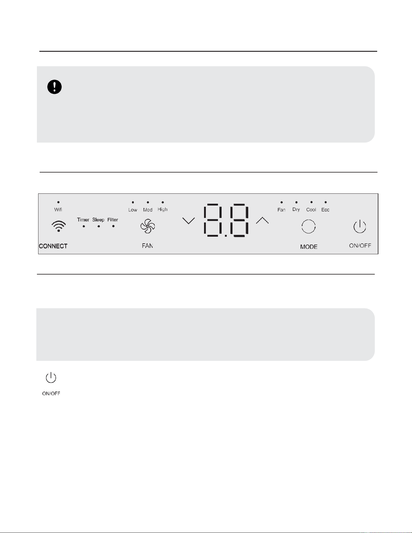
1. Using the Control Panel
ON/OFF SETTINGS
Press the power button to turn on the air conditioner.
• Select mode. See “Mode Settings” on page 15.
• Set temperature. See “Temperature Settings” on page 15.
• Select fan speed. See “Fan Speeds” on page 15.
IMPORTANT:
• If you turn off the air conditioner, wait at least 3 minutes before turning it back on. This prevents the air conditioner
from blowing a fuse or tripping a circuit breaker.
• Air conditioner in the Cool mode or Dry mode operation limits: Outdoor 64.4-109.4°F (18-43 °C), ≤ 80% RH; indoor
62.6-89.6°F (17-32°C), ≤ 80% RH.
• Air conditioner in the Heat mode operation limits: Outdoor 19.4-75.2°F (-7-24 °C), ≤ 80% RH; indoor 32-80.6°F
(0-27°C), ≤ 80% RH.
• In the event of a power failure, your air conditioner will operate at the previous settings when the power is restored.
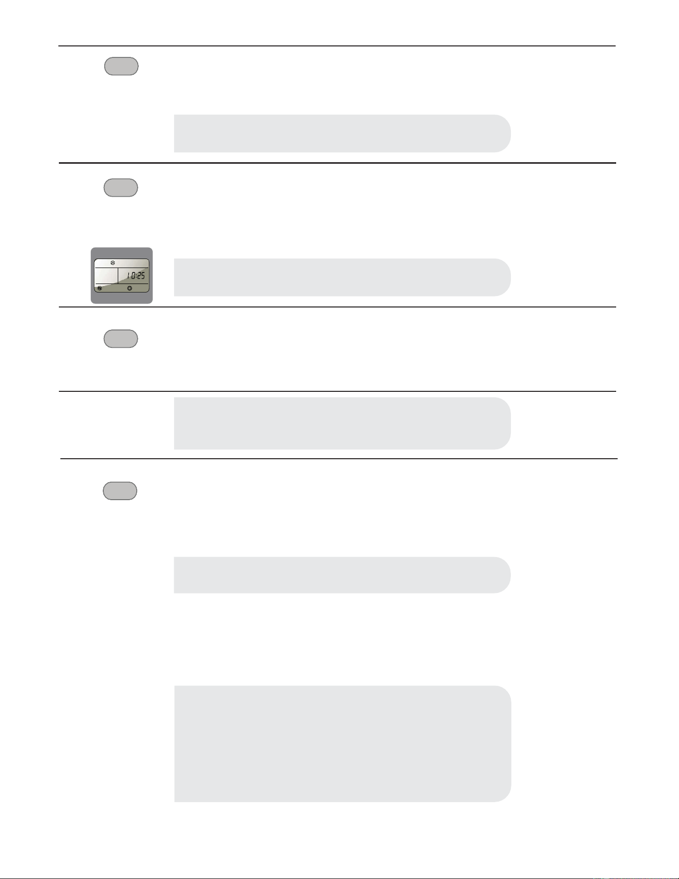
NOTE:
When the air conditioner is turned on for the first time after it is plugged in, the display will show the current set temperature and
will run in the ECO control.
After cleaning and replacing the filter, press the POWER button for resetting and the FILTER light will go off.
0
•
• • • • •
•
•
-
-
Wifi
Low
Med
High
I I I I
F
an
Dry
Cool
E
co
~
Tim
er Sleep Filter
~
V
- -
A
0
(0
-
• •
•
I I I I
•
-
■
-
CONNECT
FAN
MODE
ON/OFF
ON
/OFF
18
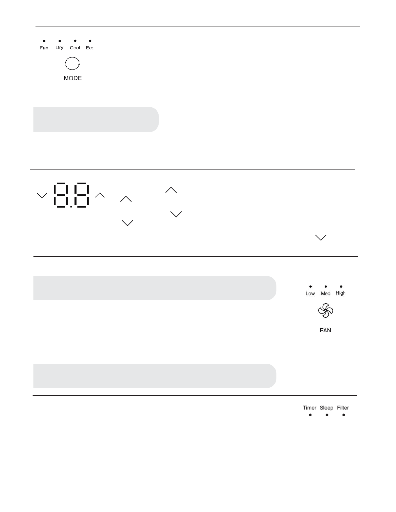
MODE SETTINGS
• Press MODE repeatedly until you see the indicator light glow for the desired setting.
• Choose Fan, Dry, Cool, Eco.
• FAN - To select Fan Only mode.
• Dry - Dries the room. The air conditioner automatically selects the temperature. Fan runs at Low
speed only.
• Cool - Cools the room.
• Eco - Cools the room and saves energy.
• In ECO mode, the fan will continue to run after the compressor shuts off for 2 minutes (4 minutes for the first time), then the fan will
shut off for 10 minutes.The fan then cycles for intervals of 2 minutes on and 10 minutes off until the room temperature is above the
set temperature, at which time the compressor turns back on and Cooling resumes. Select ECO mode to initiate this function.
TEMPERATURE SETTINGS
Press the plus UP button to raise the temperature. Each time you press or hold the plus UP
button, the temperature will go up 1 °F (1 °C) until it reaches 86°F (30°C).
Press the minus DOWN button to lower the temperature. Each time you press or hold the DOWN
button, the temperature will go down 1 °F (1 °C) until it reaches 61 °F (16°C).
To change the temperature display from °F to °C: Press both the MODE and DOWN buttons at
the same time for 5 seconds to switch the display from °F to °C.
FAN SPEEDS
• Press FAN until you see the indicator light glow for the desired setting.
• Choose High, Med, Low.
• High - for maximum cooling
• Med - for normal cooling
• Low - for quieter cooling
TIMER, SLEEP, FILTER FUNCTIONS
• The LED light on control panel for Timer, Sleep, Filter.
• For function operation, see ´´Using the Remote Control´´.
NOTE:
Dry mode should not be used to cool the room.
NOTE:
The Fan button will operate only when the Fan, Cool, ECO or Heat mode has been selected.
NOTE:
In ECO mode,the Fan will run at low speed when compressor turns off.
• • • •
Fa
n Dry
Cool
Eco
0
MODE
V
V
V
V
• • •
Low
Med
H
ig
h
FAN
Ti
me
r Sleep Filter
• • •
19
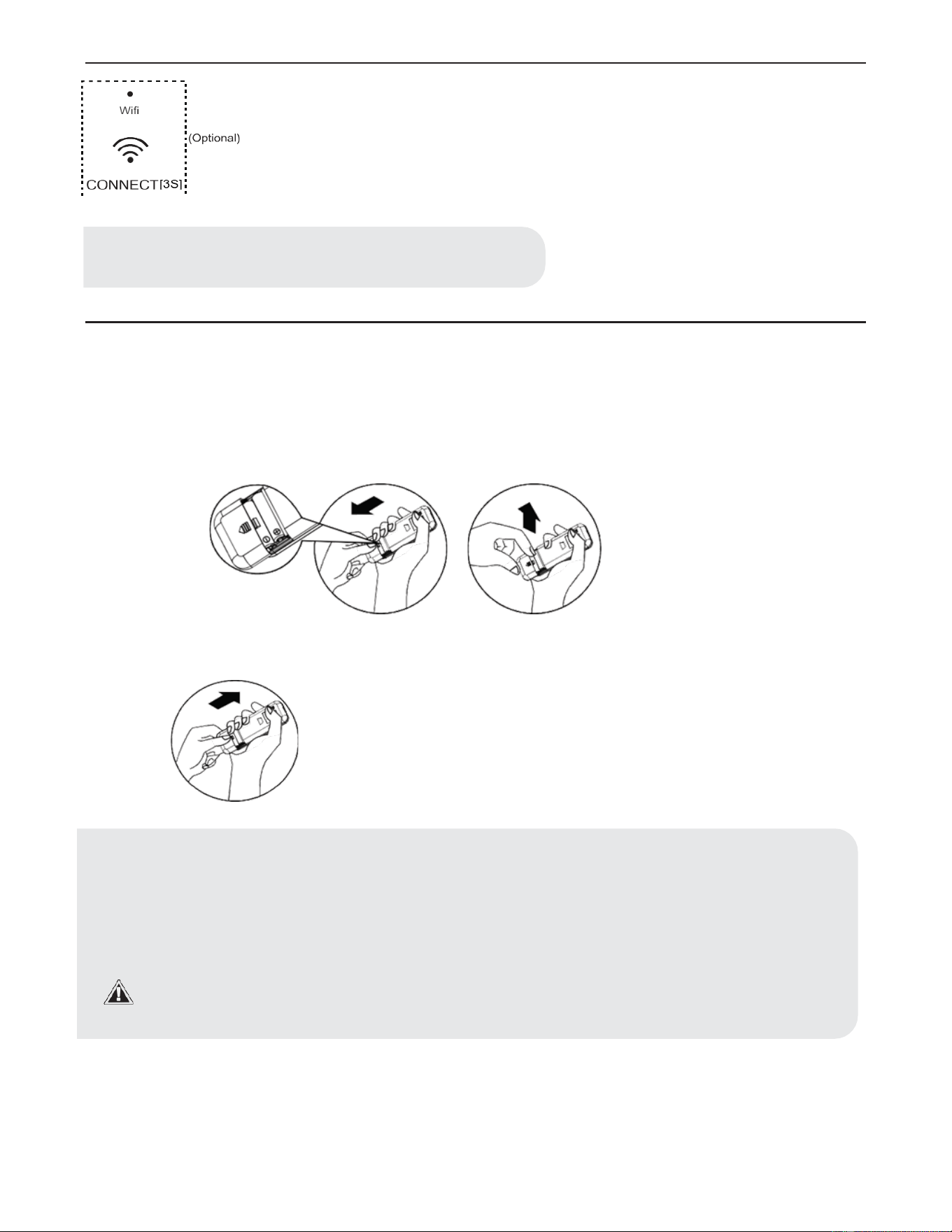
WI-FI
• WI-FI control is available for connected models with this logo on control panel.
• Press the button for 3 seconds; the LED starts to flash.
• After the WI-FI connects to the router, the LED will remain on.
2. Using the Remote Control
INSERT THE BATTERIES
• Remove the battery cover along the arrow direction.
• Insert new batteries making sure that the (+) and (-) of battery are matched correctly.
• Re-attach the cover by sliding it back into position.
NOTE:
WI-FI control is available only for WI-FI control models.
NOTE:
• Use 2 standard AAA (1.5 volt) batteries. Do not use rechargeable batteries.
• Replace batteries with new ones of the same type when the display becomes dim, or after 6 months.
• When replacing batteries, always replace both batteries with new batteries. Do not mix old and new batteries. Do not
mix alkaline, standard (carbon-zinc), or rechargeable (ni-cd, ni-mh, etc) batteries.
• If the air conditioner will not be used for an extended period of time, remove the batteries from the remote.
• Do not use the remote if the batteries have leaked.
The chemicals in batteries could cause burns or other health hazards.
• Do not dispose of batteries in a fire. Batteries may explode or leak.
•
Wifi
;(
Opt
ional)
.
CONNECTf3S
1:
20
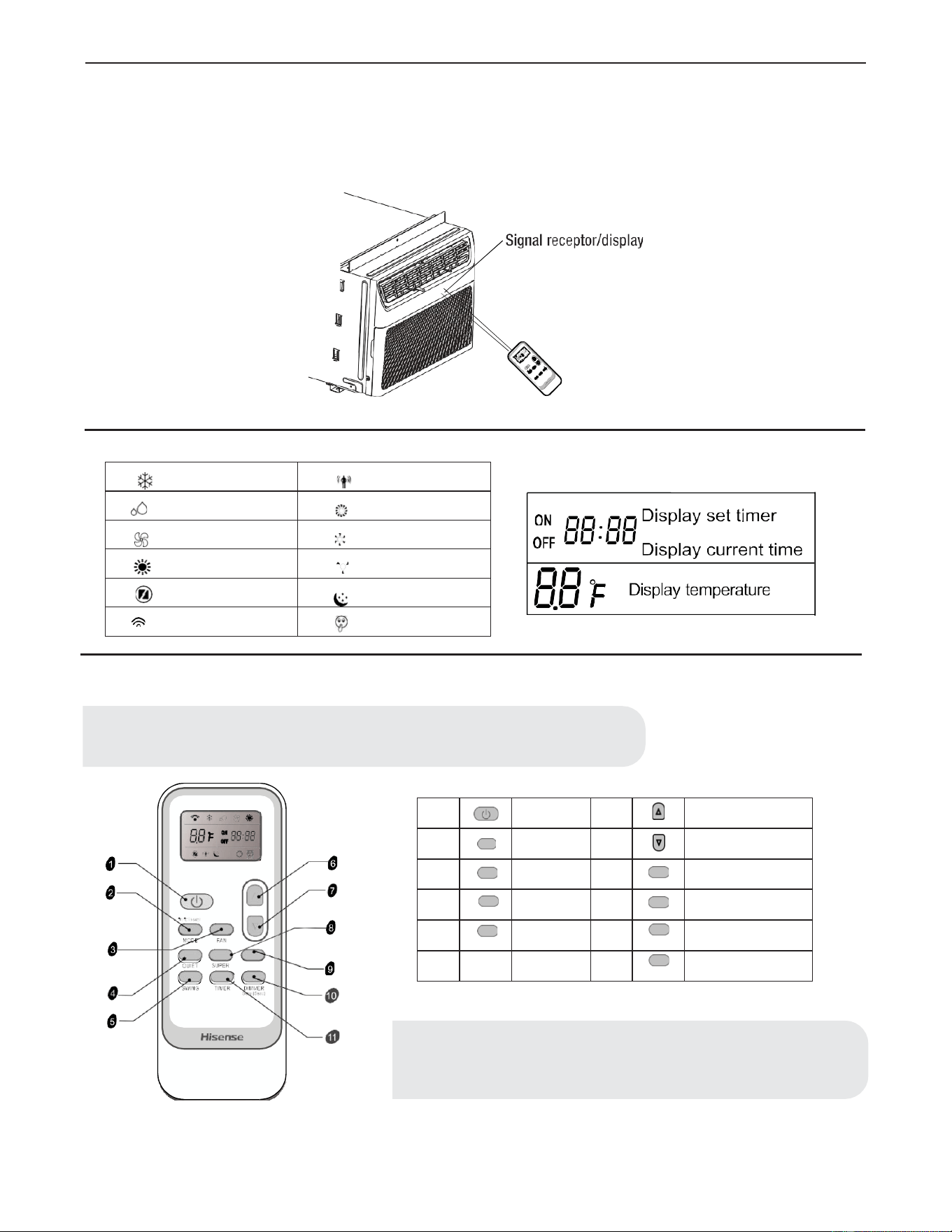
HOW TO USE
• To operate the room air conditioner, aim the remote control at the signal receptor. The remote control will operate the air conditioner
at a distance of up to 23 (7m) when pointed at the signal receptor.
INDICATION SYMBOLS
BUTTON AND FUNCTION
1
ON/ OFF
6
UP
2
°F/°C [ 5 SEC]
MODE
MODE
7
DOWN
3
FAN
FAN
8
SUPER
SUPER
4
QUIET
QUIET
9
FILTER
FILTER
5
SWING
SWING
10
DIMMER
Sleep [ 5 sec]
DIMMER or SLEEP
11
TIMER
TIMER ON/ OFF
FILTER
NOTE:
Press and hold the MODE button on the remote for 5 seconds to switch the
temperature display from degrees Fahrenheit (°F) to degrees Celsius (°C).
Cooling indicator
Eco indicator
Dry indicator
High fan speed
Fan only indicator
Medium fan speed
Heating indicator
Low fan speed
Super indicator
Sleep indicator
Signal transmit
Quiet indicator
NOTE:
Remote control may differ in appearance. Swing function is not available on this models.
*
cD
~
~
*
~
@
$
8B
r=
:
asBB
• ,
...
oe
Hisense
I
If
qt'
:d•,:_
·
-,
~~
...
·,·
• >
\;;;
~
@
Signal
receptor/display
ON
OO.
OO Display set
timer
OFF
LIU·
LICI
Display current time
0 0 °F Display temperatu
re
LI.LI
~
(!)
C}
0
21
MODE
QUIET
• Press the Quiet button to set or cancel the Quiet Mode operation.
SUPER
Fast cooling
SUPER
The SUPER button is used to start or stop fast cooling.
• Press the SUPER button. The air conditioner automatically sets the fan speed to High and the tempera-
ture to 16°.
• To turn off Super control. press MODE, FAN, QUIET or SUPER button on the remote control.
FILTER
FILTER
• When the Filter indicator light is lit, remove, clean and replace the air filter. See “Cleaning the Air
Filter”.
• Press Power button on the machine or FILTER button on remote to reset the filter after cleaning and
replacing the air filter.
DIMMER
Sleep (5 sec)
SLEEP
The SLEEP mode can be set in Cool, Dry or ECO mode. When in sleep mode, the unit will utilize lower,
quieter fan speeds and automatic temperature adjustments offering 8 hours of optimal sleeping conditions
before shutting off.
• Press MODE to select Cool, Dry or ECO.
• Press the up or down arrow button to set the temperature.
• Press and hold the DIMMER button on the remote for 5 seconds to switch the DIMMER mode to SLEEP
mode.
• After 10 seconds, the light on the control panel display will dim.
• To turn off Sleep control, press MODE, FAN, SLEEP or wait 8 hours for Sleep control to turn off
automatically.
NOTE:
It takes about 2 to 3 minutes to fully enter the quiet mode.
NOTE:
It takes about 2 to 3 minutes to fully enter the quiet mode.
NOTE:
Sleep control cannot be selected in Fan mode.
NOTE:
When the light is on, it will remain on for 180 hours or until you press Clean
Filter button.
NOTE:
When you press sleep button:
• The appliance will stop operation automatically after operating for 8
hours.
• Fan speed is automatically set at low speed.
• In the Cooling mode, Dry mode, and ECO mode, the set temperature will
increase by 4°F (2°C) at most, during 2 hours, and continues running at
that temperature until auto shut off.
C)
C)
*
_i..
)
D=~
.-
0
C)
C)
22
TIMER
TIMER
Setting the Air Conditioner to Turn ON:
• Plug in the air conditioner and use the remote to power it on.
• Use the remote to set the desired mode, temperature, fan speed, etc.
• Use the remote to power off the air conditioner.
• Press TIMER on the remote and use the UP, DOWN buttons to set the desired delay time until the air
conditioner turns ON. The delay time can be set from 0 to 24 hours in one-hour increments.
• Press TIMER again to enter the delay time. The TIMER LED on the air conditioner illuminates, and the
delay time appears on the remote.
Setting the Air Conditioner to Turn OFF:
• Plug in the air conditioner and use the remote to power it on.
• Use the remote to set the desired mode, temperature, fan speed, etc.
• Press TIMER on the remote and use the UP, DOWN buttons to set the desired delay time until the air
conditioner turns ON. The delay time can be set from 0 to 24 hours in one-hour increments.
• Press TIMER again to enter the delay time. The TIMER LED on the air conditioner illuminates, and the
delay time appears on the remote.
To cancel TIMER:
• Press the TIMER button again; when a Beep is heard and the indicator disappears, the TIMER mode has
been canceled.
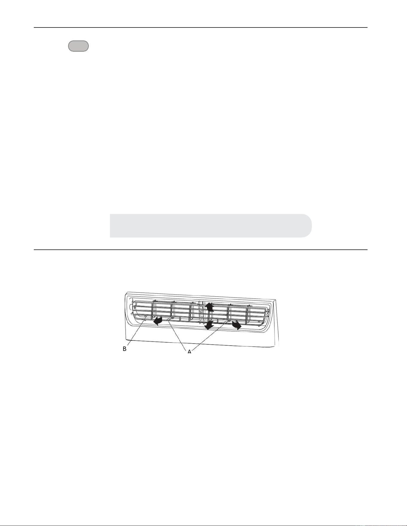
3. Changing Air Direction
• Use the Vertical Level Vane (A) to direct the air right or left. Use the whole cartridge (B) to direct air up, down or straight ahead.
NOTE:
The TIMER function can only be set using the remote.
C)
.-
(r,r
r
r·:-
I
B
I
ii
ff
~
\
'I
,,
1
),
"'
,
111/)
"
!!
'If/ I
-
~
;,
7'
~/
/
23
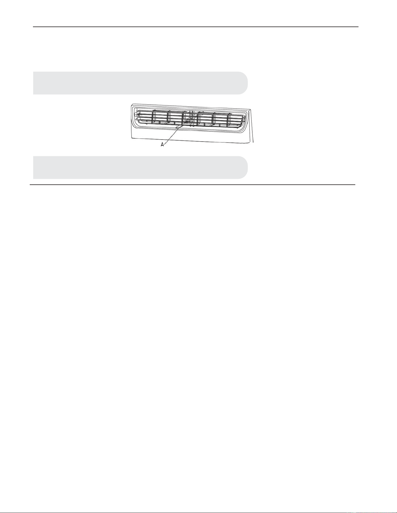
4. Exhaust Air Vent
• Pull out the exhaust air vent control to Open the exhaust air vent and draw stale or smoky air from the room.
• Push in the exhaust air vent control to close the exhaust air vent for maximum continuous cooling.
5. Normal Sounds
When your air conditioner is operating normally, you may hear sounds such as:
• Droplets of water hitting the condenser, causing a pinging or clicking sound. The water droplets help cool the condenser.
• Air movement from the fan.
• Clicks from the thermostat cycle.
• Vibrations or noise due to poor wall or window construction.
• A high-pitched hum or pulsating noise caused by the modern high-efficiency compressor cycling on and off.
NOTE:
The exhaust air vent control is available only for 12K\14K models.
NOTE:
The exhaust air vent control will function only when the fan is running.
A

Care and Cleaning
24
Your new air conditioner is designed to give you many years of dependable service. This section tells you how to clean and care for your air
conditioner properly. Call your local authorized dealer for an annual checkup. Remember the cost of this service call is your responsibility.
CLEANING THE AIR FILTER
The air filter is removable for easy cleaning. A clean filter helps remove dust, lint, and other particles from the air and is important for best
cooling and operating efficiency. Check the filter every 2 weeks to see whether it needs cleaning.
• Turn off the air conditioner
• Open the front panel. Grasp the filter by the handle and pull it out.
• Use a vacuum cleaner to clean the air filter. If the air filter is very dirty, wash it in warm water with a mild detergent. Do not wash the
air filter in the dishwasher or use any chemical cleaners. Air dry the filter completely before replacing to ensure maximum efficiency.
• Replace the air filter back into the air conditioner.
CLEANING THE FRONT PANEL
• Turn off the air conditioner.
• Clean the front panel with a soft, damp cloth.
• Air dry the front panel completely.
REPAIRING PAINT DAMAGE
Check once or twice a year for paint damage. This is very important, especially in areas near oceans or where rust is a problem. If needed,
touch up with a good grade enamel paint.
ANNUAL MAINTENANCE
Your air conditioner needs annual maintenance to help ensure steady, top performance throughout the year. Call your local authorized dealer
to schedule an annual checkup. The expense of an annual inspection is your responsibility.
REMOVING AC FROM WINDOW
• Turn AC off, and disconnect power cord.
• Remove sash seal from between windows and unscrew safety lock.
• Remove screws installed through frame and frame lock. Remove the EVA foam (E-star models only).
• Close the curtain housing.
• Keeping a firm grip on air conditioner, raise sash and carefully remove.
• Be careful not to spill any standing water while lifting unit from window. Store parts with the AC.
NOTE:
Do not operate the air conditioner without the filter in place.
Troubleshooting
25
Problem
Air conditioner will not operate.
• The power supply cord is unplugged. Plug into grounded 3-prong outlet. See “Electrical Requirements”.
• The power supply cord has tripped (RESET button has popped out). Press and release RESET to resume operation.
• A household fuse has blown, or circuit breaker has tripped. Replace the fuse or reset the circuit breaker. If the problem continues, call
an electrician. See “Electrical Requirements”.
• The Power button has not been pressed. Press the Power button.
• The local power has failed. Wait for power to be restored.
Problem
Air conditioner blows fuses or trips circuit breakers.
• Too many appliances are being used on the same circuit. Unplug or relocate appliances that share the same circuit.
• Time-delay fuse or circuit breaker of the wrong capacity is being used. Replace with a time-delay fuse or circuit breaker of the correct
capacity. See “Electrical Requirements”.
• An extension cord is being used. Do not use an extension cord with this or any other appliance.
• You are trying to restart the air conditioner too soon after turning off the air conditioner. Wait at least 3 minutes after turning off the
air conditioner before trying to restart the air conditioner.
Problem
Air conditioner power supply cord trips (reset button pops out).
• Disturbances in your electrical current can trip (RESET button will pop out) the power supply cord. Press and release RESET to
resume operation.
• Electrical overloading, overheating, cord pinching or aging can trip (RESET button will pop out) the power supply cord. After
correcting the problem, press and release RESET to resume operation.
For additional support contact:
richmondac@cssupport247.com
1-800-899-1485
Solution
DANGER: ELECTRICAL SHOCK HAZARD
• Plug into a grounded 3-prong outlet.
• Do not remove ground prong.
• Do not use an adapter.
• Do not use an extension cord.
• Failure to follow these instructions can result in death, fire, or electrical shock.
Solution
Solution
NOTE:
A damaged power supply cord must be replaced with a new power supply cord obtained from
the product manufacturer and must not be repaired.
A

26
Problem
Air conditioner seems to run too much.
• The current air conditioner replaced an older model. The use of more efficient components may cause the air conditioner to run longer
than an older model, but the total energy consumption will be less. Newer air conditioners do not emit the “blast” of cold air you may
be accustomed to from older air conditioners, but this is not an indication of lesser cooling capacity or efficiency. Refer to the
efficiency rating (EER) and capacity rating (in Btu/h) marked on the air conditioner.
• The air conditioner is in a heavily occupied room, or heat producing appliances are in use in the room. Use exhaust vent fans while
cooking or bathing and try not to use heat producing appliances during the hottest part of the day. A higher capacity air conditioner
may be required, depending on the size of the room being cooled.
Problem
Air conditioner cycles on and off too much or does not cool.
• The air conditioner is not properly sized for your room. Check the cooling capabilities of your room air conditioner. Room air
conditioners are not designed to cool multiple rooms.
• The filter is dirty or obstructed by debris. Clean the filter.
• The inside evaporator and outside condenser coils are dirty or obstructed by debris. See Annual Maintenance.
• There is excessive heat or moisture (open container cooking, showers, etc.) in the room. Use a fan to exhaust heat or moisture from
the room. Try not to use heat producing appliances during the hottest part of the day.
• The louvers are blocked. Install the air conditioner in a location where the louvers are free from curtains, blinds, furniture, etc.
• The temperature of the room you are trying to cool is extremely hot. Allow extra time for the air conditioner to cool off a very hot
room.
• Windows or doors to the outside are open. Close all windows and doors.
• The Temp control is not at a cool enough setting. Adjust the Temp control to a cooler setting by pressing the minus button to reduce
the temperature. Set the Fan Speed control to the highest setting.
Problem
Water drips from cabinet into your house.
• The air conditioner is not properly leveled. The air conditioner should slope slightly downward toward the outside. Level the air
conditioner to provide a downward slope toward the outside to ensure proper drainage. See the Installation Instructions.
Solution
Solution
Solution
NOTE:
Do not drill a hole in the bottom of the metal base and condensate pan.
27
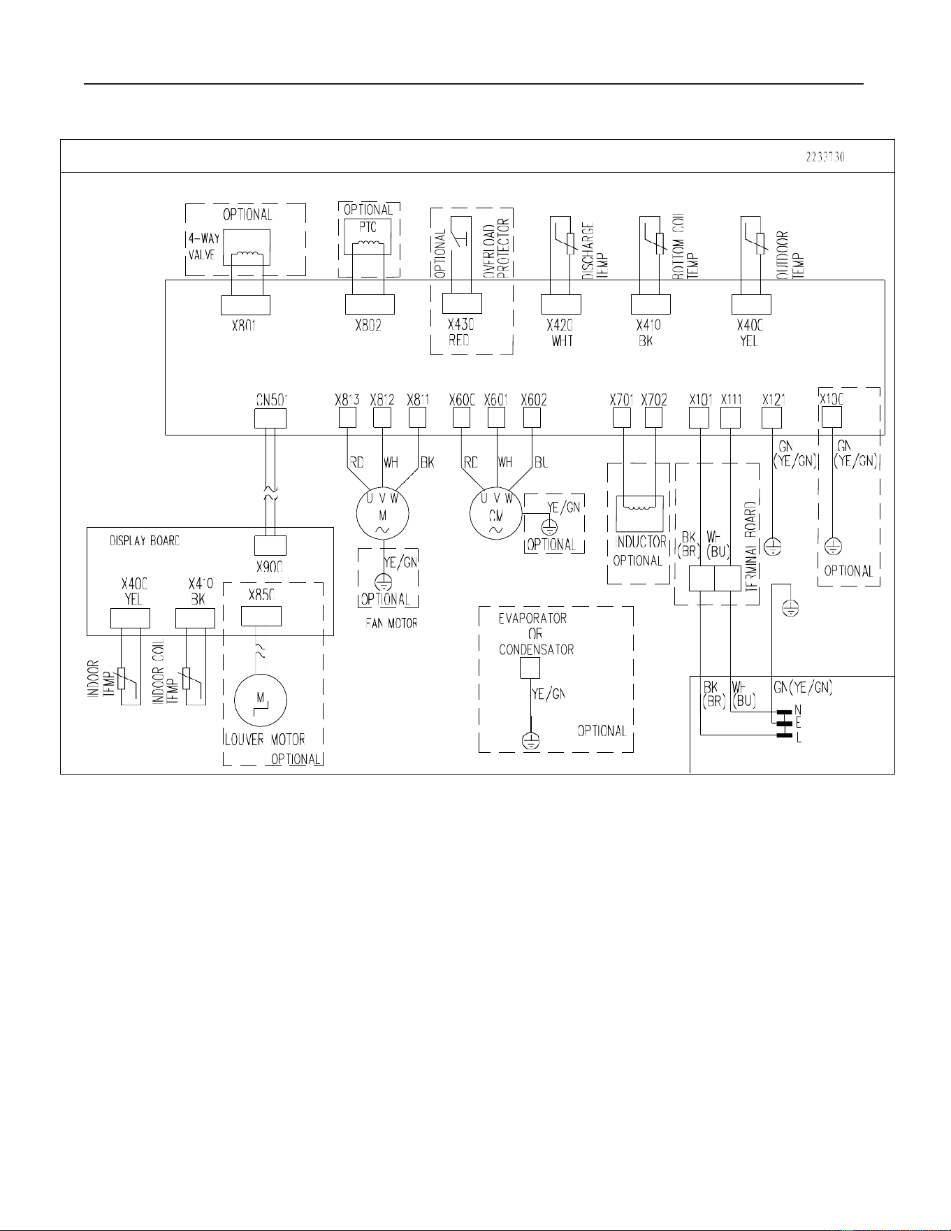
Circuit diagram
DI
SPLAY
BOAR
D
X400
YEL
1
OPTIO
N
AL
7
1
4-WAY
I
~ VE
__
_j
X80
1
CN501
:~
I~
IL
OUVER
M
OTOR
L _
_QpTION
AlJ
I
X802
I X
430
I
X420
L
RED
- J
WHT
X4
10
BK
X400
Y
EL
0:::
0
0
o
n...
>-
::::E
=
u..J
0>-
22
3373
0
X8
13
X8
12
X81
1
X600
X60
1
X602
X70
1
X702
X101 X
111
X1
21
~TI
ONA
LJ
F
AN
M
OTOR
,-----7
I E
VA
POR
ATOR
OR
I
CONDENSA
TOR
I
I
r I
I
YE/GN
I
I I
L
7
OPT
I
ONA
L I
_____
_J
GN
(YE/GN)
I
I
I
I
'...L:
I
I
O;TIO
NAL
I
L _
_J
BK
WH
GN(YE/GN)
(BR)
"-
( B
---'-
U )
----+-_
N
E
c__
___
,..L

INSTRUCCIONES DE INSTALACIÓN Y USO
Modelo:
RMV08A10A, Richmond Inversor, 8k
RMV10A10A, Richmond Inversor, 10k
RMV12A10A, Richmond Inversor, 12k
Para consultas sobre las características, funcionamiento/ rendimiento, piezas o servicio,
llame al:

Tabla de contenidos
Información de Seguridad ........................................................................................ 30
Instrucciones Importantes de Seguridad. .......................................................... 30
Eliminación del Aparato. .................................................................................. 30
Pre-Instalación .......................................................................................................... 34
Requisitos Eléctricos. ....................................................................................... 34
Método de Conexión a Tierra Recomendado. ..................................................34
Requisitos para el Cableado. ............................................................................ 34
Cable de Alimentación. .................................................................................... 35
Planificación de la Instalación. ........................................................................ 35
Hardware Incluido. ........................................................................................... 36
Desembalaje del aire acondicionado................................................................ 37
Requisitos de Ubicación. .................................................................................. 37
Medidas de Apertura de la Ventana. ................................................................. 39
Si el Aire Acondicionado está Bloqueado por la ventana de tormenta. .......... 39
Instalación ................................................................................................................. 40
Operación .................................................................................................................. 44
Uso del Aire Acondicionado. ........................................................................... 44
Uso del Control Remoto. ................................................................................. 46
Cambio en la Dirección del Aire. ................................................................... 49
Ventilación del Aire de Escape. ....................................................................... 50
Sonidos Normales. ........................................................................................... 50
Limpieza y cuidado .................................................................................................. 51
Limpieza del Filtro del Aire. ............................................................................ 51
Limpieza del Panel Frontal. ............................................................................. 51
Reparación de la pintura dañada. ..................................................................... 51
Mantenimiento Anual. ......................................................................................51
Extracción del Aire Acondicionado de la Ventana. ......................................... 51
Resolución de problemas ......................................................................................... 52
Diagrama de circuito .............................................................................................. 54
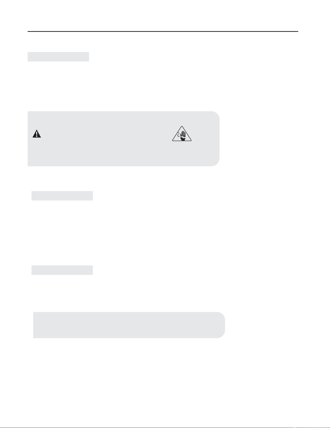
Información de Seguridad
Hemos proporcionado mensajes de seguridad importantes
en este manual y en el aparato. Lea y siga siempre todos los
mensajes de seguridad.
Explicación de los símbolos mostrados en la unidad.
ADVERTENCIA
Este símbolo muestra que este aparato utiliza un refrigerante
inflamable.
Si hay una fuga de refrigerante y queda expuesto a una fuente
de ignición externa, existe el riesgo de incendio.
PRECAUCIÓN
Este símbolo muestra que se debe leer detenidamente el manual
de funcionamiento.
PRECAUCIÓN
Este símbolo muestra que un técnico de mantenimiento debe
manipular este equipo en referencia al manual de instalación.
PRECAUCIÓN
Este símbolo muestra que hay información disponible, como el
manual de funcionamiento o el manual de instalación.
Instrucciones importantes de seguridad
Para reducir el riesgo de incendio, descarga eléctrica o lesiones
al usar el aire acondicionado, sigas estas precauciones básicas:
• Conécte a una toma con 3 clavijas con conexión a
tierra.
• No quite la terminal a tierra.
• No utilice el adaptador.
• No utilice el cable de extensión.
• Desenchufe el aire acondicionado antes del manten
imiento.
• Se necesitan dos o más personas para mover e instalar
el aire acondicionado.
Eliminación del aparato
• Antes de desechar el aparato, hay que quitar las pilas y
eliminarlas o reciclarlas adecuadamente.
• Cuando necesite eliminar el aparato, consulte con
nuestro distribuidor. Si las tuberías se retiran incorrecta
mente, podría soplar refrigerante que entre en contacto
con su piel, provocándoles lesiones. La liberación de
refrigerante a la atmósfera también daña el medio
ambiente.
• Nunca almacene ni envíe el aire acondicionado boca
abajo ni de lado para evitar daños en el compresor.
• Este aparato no se diseña para usarse por personas
(incluso niños) con capacidades físicas, sensoriales y
mentales reducidas o con falta de experiencia y
conocimiento a menos que hayan sido supervisados o
instruidos sobre el uso del aparato por una persona
responsable por su seguridad. Se debe supervisar a los
niños para asegurarse de que no jueguen con el aparato.
• En la placa del aire acondicionado, se muestra el
diagrama de cableado.
30
Peligro: Este símbolo le alerta de un peligro potencial
que, si no se evita, resultará en la muerte o lesiones
graves.
Advertencia: Este símbolo le alerta de un peligro
potencial que, si no se evita, podría resultar en la muerte
o lesiones graves.
Precaución: Este símbolo le alerta de un peligro
potencial que, si no se evita, puede resultar en lesiones
leves o moderadas.
Precaución: Riesgo de Incendio o Explosión. Esta
unidad contiene refrigerante inflamable.
Debe seguir las medidas de precaución adicionales.
• No utilice medios para acelerar el proceso de
descongelación o de limpieza que no sean los
recomendados por el fabricante.
• Se debe almacenar el aparato en una sala sin fuentes
de ignición en funcionamiento continuo (por ejemplo,
llamas vivas, aparatos de gas o calentadores eléctricos
en funcionamiento).
• No perfore ni queme la tubería de refrigerante. Tenga
en cuenta que es posible que los refrigerantes no
tengan olor.
• Debe cumplir con las regulaciones nacionales de gas
natural.
• Mantenga los orificios de ventilación libres de
obstrucciones.
• La cantidad máxima de carga del refrigerante se
muestra en la placa del aire acondicionado.
• Debe tener mucho cuidado para evitar dañar la tubería
refrigerante al manipular, instalar y operar el aparato.
• No perfore orificios en la unidad.
• El mantenimiento, la limpieza y el servicio deben ser
realizados solo por técnicos capacitados y calificados
en el uso de refrigerantes inflamables.
• Deseche el aire acondicionado en conformidad con las
normas federales y locales. Los refrigerantes
inflamables requieren procedimientos de eliminación
especiales. Contacte a las autoridades locales para
eliminar el aire acondicionado de forma segura.
• El aparato debe almacenarse de forma que no sufra
daños mecánicos.
• Los electrodomésticos deben almacenarse en una zona
bien ventilada, cuyo tamaño corresponde al área de la
Sala de operaciones designada.
• Este producto contiene piezas pequeñas como
(baterías, tapa de batería y tornillos) que pueden
causar asfixia si son ingeridas por niños.
• Para los aparatos eléctricos equipados con calentado-
res auxiliares, la distancia mínima entre el aparato y la
superficie del combustible es de 50 cm.
A
w

Precauciones para utilizar el refrigerante R32
Para el refrigerante del sistema múltiple, vea la unidad externa
múltiple. Los procedimientos de instalaciones básicas son los
mismos a los del refrigerante convencional (R22 o R410A). Sin
embargo, preste atención a los siguientes puntos:
1. Transportación de equipos que contienen refrigerantes
inflamables
Conforme a las normativas de transportación.
2. Marcado de los equipos que utilizan señales
Conforme a las normativas locales.
3. Eliminación de equipos que contienen refrigerantes
inflamables
Conforme a las normativas nacionales.
4. Almacenamiento de equipos/electrodomésticos
El almacenamiento de equipos debería ser de acuerdo a las
instrucciones del fabricante.
5. Almacenamiento del equipo embalado (sin vender)
La protección para el almacenamiento del paquete debería ser
construida para que los daños mecánicos al equipo dentro del
paquete no causen fugas de la carga del refrigerante. El número
máximo de piezas del equipo permitido para almacenar será
determinado por las normativas locales.
6. Información del servicio
Verificación de la zona: Antes de comenzar a trabajar en los
sistemas que contienen refrigerantes inflamables, son necesarios los
controles de seguridad para minimizar los riesgos de ignición. Para
reparar el sistema refrigerante, se deben cumplir las siguientes
precauciones antes de realizar el trabajo en el sistema.
Procedimiento de trabajo: El trabajo se debe llevar a cabo bajo
procedimiento controlados para minimizar el riesgo de presencia de
gas inflamable o vapor durante la realización del trabajo.
Área general del trabajo: Todo personal de mantenimiento y los
que trabajan en el área deben ser capacitados sobre la naturaleza del
trabajo que realizan. Se deben evitar el trabajo en espacios
cerrados. El área cerca del lugar de trabajo en espacios cerrados.
El área cerca del lugar de trabajo debe estar seccionada. Asegúrese
que las condiciones dentro del área sean seguras mediante el
control de materiales inflamables.
Verificación de la presencia de refrigerante: el área debe
controlarse con un detector de refrigerante adecuado antes y
durante el trabajo para garantizar que el técnico sea consciente de la
potencial atmósfera inflamable. Asegúrese que el equipo de
detección de fugas que se utiliza sea adecuado para el uso de
refrigerantes inflamable, es decir, sin chispas, bien sellado o
intrinsecamente seguro.
Presencia de un matafuegos:Si se realiza un trabajo en caliente
sobre el equipo de refrigeración u otras partes asociadas, se debe
tener al alcance un matafuegos correcto.
Se debe contar con un extinguidor de polvo seco o C02 adyacente
al área de carga.
Fuentes de no ignición: ninguna persona que realice el trabajo en
relación al sistema refrigerante, que involucra la exposisicón de la
tubería que contiene o tuvo refrigerante inflamable, debe usar
ninguna fuente de ignición que pueda producir un riesgo de
incendio o explosión. Todas las posibles fuentes de ignición,
incluidos los cigarrillos, se deben mantener lejos del lugar de
instalación, reparación o eliminación, durante el cual, el refrigeran-
te inflamable pueda ser liberada en el espacio.
Antes de realizar el trabajo, se debe controlar el área alrededor del
equipo para garantizar que no haya peligros o riesgos del incendio.
Se debe colocar un cartel de ´´No fumar´´.
Área ventilada: Asegúrese de que el área esté en un sector abierto o
que esté en un sector bien ventilado antes de utilizar el sistemas o
realizar cualquier trabajo en caliente.
Debe haber un grado de ventilación continua durante el período en el
que se realice el trabajo.
La ventilación debería dispersar de manera segura cualquier refriger-
ante liberado y expulsarlo hacia la atmósfera.
Verificaciones del equipo: Si se cambian los componentes eléctricos,
estos deberían ser para su propósito y especificación correcta.
Siempre se deben seguir las pautas de mantenimiento y servicio del
fabricante. Si tiene alguna duda, contacte al departamento técnico del
fabricante para una asistencia.
Deben aplicarse los siguientes controles en las instalaciones que usan
refrigerantes inflamables:
-El tamaño de la carga de acuerdo con el tamaño de la habitación
dentro del cual están instalados las partes que contienen refrigerante;
-La maquinaria de ventilación y los toma corrientes funcionan de
manera correcta cuando no están obstruidos;
-La maquinaria de ventilación y los toma corrientes funcionan de
manera correcta cuando no están obstruidos;
-Si se utiliza un circuito refrigerante indirecto, el circuito secuandario
debe verificarse por la presencia de refrigerante;
-Las marcas en el equipo continúan visibles y legibles. Las marcas y
señales que son ilegibles deben corregirse;
-La tubería de refrigeración o los componentes se instalan en una
posición donde no están expuestos a ninguna sustancia que pueda
corroer los componentes que contienen el refrigerante, al menos que
los componentes que contienen el refrigerante, al menos que los
componentes estén hechos de materiales que son resistentes a la
corrosión o adecuados para protegerlos contra la corrosión.
Verificaciones de dispositivos eléctricos: La reparación y el
mantenimiento de los componentes eléctricos deben incluir los
controles iniciales de seguridad y los procedimientos de inspección de
componentes. Si ocurre una falla que puede comprometer la seguri-
dad, no se debe conectar el suministro eléctrico al circuito hasta que
se haya tratado.
Si la falla no se puede corregir inmediatamente pero es necesario
continuar con la operación, se debe utilizar una solución temporaria
correcta. Se debe informar al propietario del equipo para que todos
sepan de la situación. Los controles iniciales de seguridad incluyen:
-Que los condensadores están descargados: esto se debe realizar de
manera segura para evitar posibles chispas;
-Que no haya componentes eléctricos y cables expuestos durante la
carga, recuperación o purga del sistema;
-Que haya una conexión a tierra continua.
7. Reparación de los componentes sellados
-Durante la reparación de los componentes sellados, todos los
suministros eléctricos deben desconectarse del equipo en el que se
trabaja antes de quitar los cobertores sellados, etc.
-Si es absolutamente necesario tener un suministro eléctrico en el
equipo durante el mantenimiento, se debe colocar un detector de fugas
que funcione permanentemente en el punto más crítico para advertir
sobre potenciales situaciones de peligro.
-Se debe poner atención a lo siguiente para garantizar que, mediante
el trabajo sobre los componentes eléctricos, no se altere la caja para
que no afecte el nivel de protección.
-Esto debe incluir el daño a los cables, el excesivo número de
conexiones, terminales que no cumplen con la especificación original,
daño a los sellos, montaje incorrecto de las prensa-estopas, etc.
-Asegúrese de que el aparato esté montado de manera firme.
-Asegúrese de que los sellos o los materiales de sellado no estén
degradados ya que no sirven para su propósito que es el de evitar el
ingresp de atmósferas inflamables.
-El remplazo de las partes debe ser de acuerdo a las especificaciones
del fabricante.
31

32
-El reemplazo de las partes debe ser de acuerdo a las especifica-
ciones del fabricante.
8. Reparación de los componentes intrínsecamente seguros
-No aplique ningún inductivo permanente o cargas de capacidad al
circuito sin garantizar que no exceda el voltaje y la corriente
permitidos para el equipo en uso.
-Los componentes intrínsecamente seguros son el único tipo que
puede emplear en la presencia de una atmósfera inflamable.
-El aparato de prueba debe estar en el rango correcto. Reemplace
los componentes sólo con las piezas especificadas por el fabricante.
Otras piezas pueden producir una ignición del refrigerante en la
atmósfera debido a una fuga.
9. Cableado
-Verifique que el cableado no esté sujeto al desgaste, corrosión,
presión excesiva, vibración, bordes filosos u otros efectos adversos
del ambiente.
-El control debe tener en cuenta los efectos del tiempo o las
vibraciones continuas de fuentes como compresores o ventiladores.
10. Detección de refrigerantes inflamables
-Bajo ninguna circunstancia se pueden utilizar fuentes potenciales
de incendio en la búsqueda o detección de fugas de refrigerante.
-No se debe utilizar una lámpara de haluros (o ningún otro detector
que use llamas).
11. Métodos de detección de fugas
Los siguientes métodos de detección de fugas se consideran
aceptables para los sistemas que contienen refrigerantes inflam-
ables:
–Los detectores de fugas electrónicos se deben utilizar para detectar
refrigerantes inflamables pero puede que la precisión no sea
correcta o puede que necesite una recalibración. (El equipo de
detección se debe calibrar en un área libre de refrigerante).
-Asegúrese de que el detector no sea una fuente potencial de
incendio y sea adecuado para el uso del refrigerante.
-El equipo de detección de fugas debe fijarse a un porcentaje del
LFL del refrigerante y debe calibrarse al refrigerante empleado y
así se confirmará el porcentaje adecuado de gas (25% máximo).
-Los fluidos de detección de fugas son ideales para usar con la
mayoría de los refrigerantes; pero debe evitarse el uso de detergen-
tes que contienen cloruro ya que el cloro puede reaccionar con el
refrigerante y corroer la tubería de cobre.
-Si se presume una fuga, se deben eliminar/extinguir todas las
llamas.
-Si se encuentra una fuga del refrigerante que requiere de soldadu-
ra, se debe recuperar todo el refrigerante del sistema o aislarlo
(mediante el cierre de las válvulas) en una parte del sistema lejos de
la fuga.
-El nitrógeno libre de oxígeno (NLO) debe ser purgado a través del
sistema antes y durante el proceso de soldadura.
12. Eliminación y evacuación
-Al acceder al circuito de refrigerante para realizar las reparaciones,
o con otros fines, se deben utilizar los procedimientos convenciona-
les. Sin embargo, si se trata de refrigerantes inflamables, es
importante seguir las prácticas con la mejor precisión.
a. Eliminar el refrigerante siguiendo las regulaciones locales y
nacionales;
b. Purgar el circuito con gas inerte;
c. Evacuar (opcional para A2L);
d. Purga con gas inerte (opcional para A2L);
e. Abra el circuito cortando o soldando;
-Si la ventilación no está permitida por las normativas locales y
nacionales, la carga de refrigerante debe recuperarse en el cilindro
de recuperación adecuado. Para aparatos que contengan refriger-
antes inflamables, el sistema debe purgarse con oxígeno- nitrógeno
libre para que el aparato sea seguro para refrigerantes. Es posible
que sea necesario repetir este proceso varias veces. No debe
utilizarse aire comprimido ni oxígeno para purgar el sistema de
refrigerante.
-Para los aparatos que contengan refrigerantes inflamables, la purga
del refrigerante se realizará rompiendo el vacío del sistema con
oxígeno- nitrógeno libre y continuando el llenado hasta alcanzar la
presión de trabajo, descargándolo después de la atmósfera y
reduciéndolo finalmente al vacío (opcional para A2L). Este proceso
debe repetirse hasta que no quede refrigerante en el sistema
(opcional para A2L). Cuando se use una carga de oxígeno -
nitrógeno libre, se debe ventilar el sistema con una presión
atmosférica para permitir que tenga efecto.
-Asegúrese de que la salida de la bomba de vacío no esté cerca de
ninguna fuente potencial de ignición y pueda ventilarse.
13. Procedimientos de carga
-Además de los procedimientos de carga convencionales, se deben
seguir los siguientes requerimientos:
• Que no se produzca una contaminación de diferentes
refrigerantes cuando carga el equipo.
• Las mangueras o las conexiones deben ser tan cortas
como sean posible para minimizar la cantidad de refrigerante
contenido en ellas.
• Los cilindros se deben mantener de forma vertical.
• Que el sistema refrigerante esté en conexión a tierra antes
de cargar el sistema con refrigerante.
• Etiquetar el sistema cuando la carga se complete (si ya no
está hecho).
• Se debe tener mucho cuidado para no sobre llenar el
sistema refrigerante.
-Antes de recargar el sistema, se debe probar la presión con NLO.
-El sistema debe ser a prueba de fugas al finalizar la carga y antes
de la puesta en marcha.
-Se debe realizar un seguimiento de prueba de fugas antes de dejar
el sitio.
14. Desmantelamiento
-Antes de realizar este procedimiento, es esencial que un técnico se
familiarice con el equipo y todos sus detalles.
-Se recomienda buenas prácticas para que los refrigerantes se
recuperen con seguridad.
-Antes de realizar la tarea, se debe tomar una muestra de aceite y
refrigerante en caso de que se requiera un análisis antes de la
reutilización del refrigerante recuperado. Es esencial que la
corriente eléctrica esté disponible antes de comenzar la tarea.
a. Familiarícese con el equipo y su función.
b. Aísle el sistema eléctrico.
c. Antes de realizar el procedimiento asegúrese de que:
-Este disponible el equipo de manejo mecánico, si se requiere,
para manejar los cilindro refrigerantes.
-Este disponible todo el equipo de protección personal y se use
correctamente;
-El proceso de recuperación se supervise todo el tiempo por
una persona competente;
-El equipo de recuperación y los cilindros cumplan con los
estándares adecuados.
d. Si es posible, bombee el sistema refrigerante.
e. Si no es posible el vacío, haga un distribuidor para poder
quitar el refrigerante en varias partes del sistema.
Nota: El uso de un sellador de silicona puede inhabilitar la efectividad
de algunos tipos de equipos de detección de fugas. Los componentes
intrínsecamente seguros no tienen que ser aislados antes de trabajar en
ellos.

33
f. Asegúrese de que los cilindros estén situados en las básculas
antes de realizar la recuperación.
g. Inicie la máquina de recuperación y opere según las instruc-
ciones del fabricante.
h. No sobrellene los cilindros. (No más que 80% del volúmen
líquido de la carga).
i. No exceda el máximo de la presión de trabajo en el cilindro,
aunque sea temporalmente.
j. Cuando los cilindros se hayan llenado correctamente y se haya
completado el proceso, asegúrese de que los cilindros y el equipo se
retiren del lugar y que se cierren todas las válvulas de aislamiento
en el equipo.
k. No se debe cargar el refrigerante recuperado en otro sistema
refrigerante al menos que se haya limpiado y verificado.}
15. Etiquetado
-El equipo debe estar etiquetado para indicar que ha sido desmante-
lado y se ha vaciado al refrigerante.
-La etiqueta debe estar con fecha y firma.
-Asegúrese de que haya etiquetas en el equipo que mencionen que
el equipo contiene refrigerente inflamable.
16. Recuperación
-Cuando quite el refrigerante del sistema, ya sea para un manten-
imiento o desmantelamiento, se recomienda buenas prácticas para
que el refrigerante se elimine de manera segura.
-Cuando transfiera el refrigerante en los cilindros, asegúrese que
sólo el refrigerante adecuado se empleen los cilindros de
recuperación.
-Garantice un número correcto de cilindros para mantener
disponible la carga total del sistema.
-Todos los cilindros que se utilizan están designados para la
recuperación del refrigerante y etiquetados para el refrigerante (es
decir, cilindros especiales para la recuperación del refrigerante).
-Los cilindros deben contar con la válvula liberadora de presión y
deben estar asociados al corte de válvulas y en buen estado.
-El equipo de recuperación debe estar en buen estado con un set de
instrucciones relacionado al equipo que se maneja y debe ser
adecuado para la recuperación de refrigerante inflamable.
-Además, debe estar disponible un juego de básculas calibradas y
en buen estado.
-Las mangueras deben contar con acoplamientos de desconcexión
sin fugas y deben estar en buenas condiciones.
-Antes de utilizar la máquina de recuperación, verifique que esté en
buen estado, tenga un buen mantenimiento y que cualquier
componente eléctrico esté sellado para evitar incencios en caso de
liberación del refrigerante.
-Si tiene dudas, consulte con el fabricante.
-El refrigerante recuperado debe devolverse al proveedor del
refrigerante en el cilindro correcto y con la nota de Transferencia de
residuos.
-No mezcle refrigerantes en las unidades de recuperación y
especialmente en los cilindros.
-Si los compresores o los compresores de aceite se quitan,
asegúirese de que sean evacuados a un nivel aceptable para que el
refrigerante inflamable no permanezca con el lubricante.
-El proceso de evacuación se debe realizar antes de devolver el
compresor al proveedor.
-Sólo se debe emplear calor eléctrico al compresor para acelerar el
proceso.
-Cuando se drene el aceite del sistema, se debe realizar de manera
segura.
34
Pre-Instalación
REQUISITOS ELÉCTRICOS
MÉTODO DE CONEXIÓN A TIERRA RECOMENDADO
Este aire acondicionado debe conectarse a tierra. Este aire acondicionado está equipado con un cable de alimentación con un enchufe de
tres clavijas con conexión a tierra. El cable debe estar enchufado a una toma de tres clavijas y debe tener una conexión a tierra de confor-
midad con todos los códigos y ordenanzas locales. En caso de no disponer de un tomacorriente, es responsabilidad del cliente solicitar a un
instalador eléctrico cualificado instale una toma de tres clavijas con conexión a tierra adecuada.
Es responsabilidad del cliente:
• Contactar con un instalador eléctrico cualificado.
• Garantizar que la instalación eléctrica sea adecuada y conforme al código eléctrico nacional, la última edición de ANSI/NFPA 70
y todos los códigos y ordenanzas locales.
Las copias de las normas mencionadas se pueden obtener de:
Asociación Nacional de Protección contra el Fuego
1 Batterymarch Park
Quincy, Ma 02169-7471
www.nfpa.org
REQUISITO PARA EL CABLEADO
ADVERTENCIA: Riesgo de Descarga Eléctrica
-Conéctelo a una toma con 3 clavijas con conexión a tierra.
-No quite la terminal a tierra.
-No utilice el adaptador.
-No utilice el cable de extensión.
-Pueden producirse incendios, descargas eléctricas o la muerte si no se siguen estas
instrucciones.
Fusible de acción retarda (o disyuntoe)
Fuente de alimentación
Modelo
13A
15A
115V
103.5V mín
126.5V máx
8K BTU solo frío
10K BTU solo frío
12K BTU solo frío
14K BTU solo frío
w
w
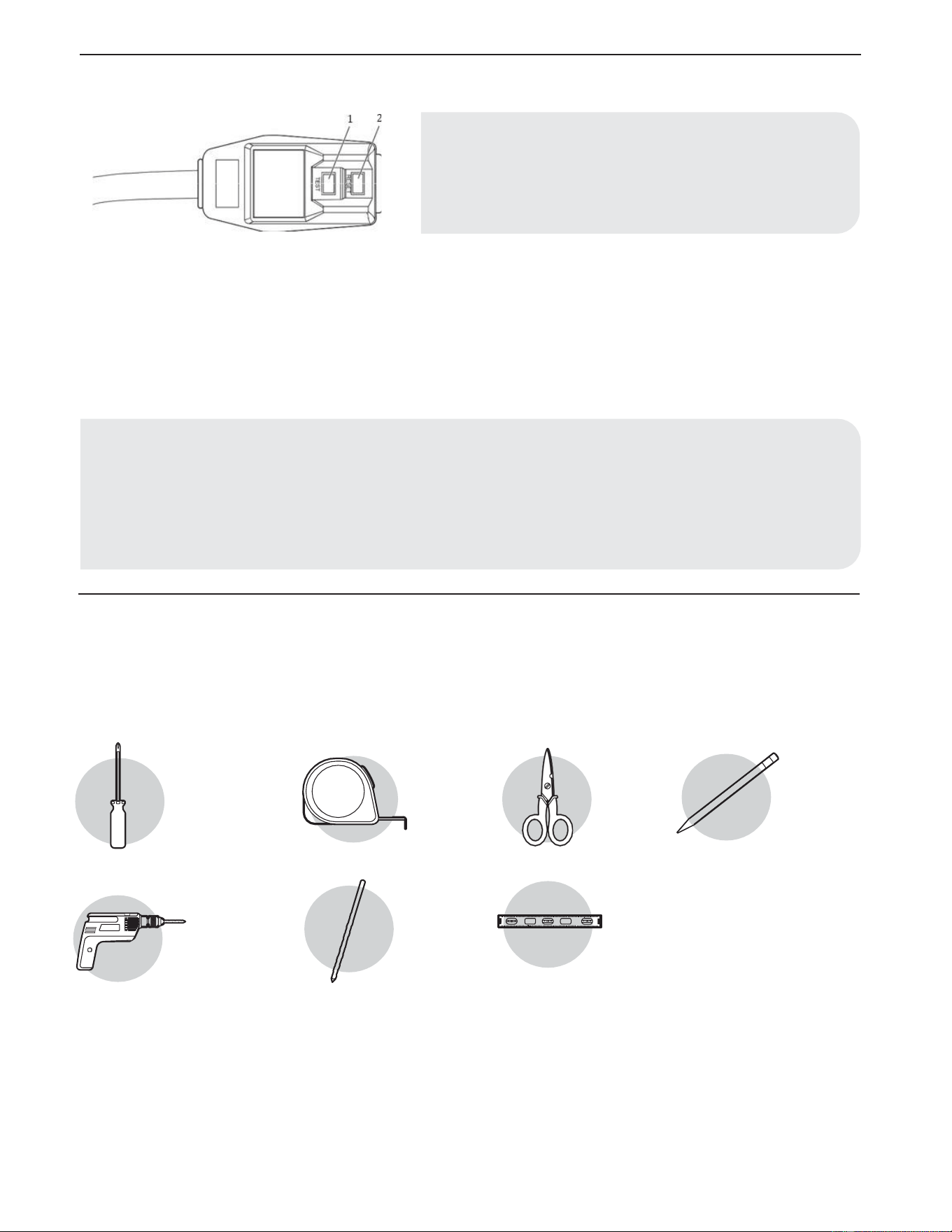
35
CABLE DE ALIMENTACIÓN
Para probar su cable de alimentación:
1. Conecte el cable de alimentación a un tomacorriente de 3 patas con conexión a tierra.
2. Presione RESET (2) (en algunos dispositivos se enciende una luz verde).
3. Presione TEST (1) y escúche el clic. El botón RESET se activará y, en algunos dispositivos, se apagará la luz verde.
4. Presione y suelte RESET (2) y escuche el clic. El botón RESET se activará y, en algunos dispositivos, se apagará la luz verde. El cable
de alimentación está listo para funcionar.
PLANIFICACIÓN DE LA INSTALACIÓN
Reúna las herramientas y piezas necesarias antes de empezar la instalación. Lea y siga las instrucciones proporcionadas con las
herramientas aquí descritas.
HERRAMIENTAS REQUERIDAS
Destornillador
Phillips
Taladro
inalámbrico
Cinta métrica
Broca de 1/8
pulg.
Tijeras
Nivel
Lápiz
NOTE: Su aire acondicionado puede diferir del que se muestra aquí. Este
aire acondicionado está equipado con un cable de alimentación por UL.
Este cable de alimentación contiene electrónica avanzada que detecta la
corriente residual. Si el cable está aplastado, la electrónica detecta la
corriente residual y la energía se desconectará en una fracción de
segundos.
NOTE:
• Se debe reemplazar el cable de alimentación si falta o se activa el momento de presionar el botón de prueba o si falla al reinciar.
• No utilice un cable de alimentación como un interruptor off/on. El cable de alimentación está diseñado como un dispositivo de
protección.
• Se debe reemplazar el cable de alimentación dañado por un cable nuevo que se obtiene del fabricante; no se debe reparar.
• El cable de alimentación contiene piezas que el usuario no puede reparar. Si abre la caja a aprueba de alteraciones, anulará todas
las garantías y demandas de rendimiento.
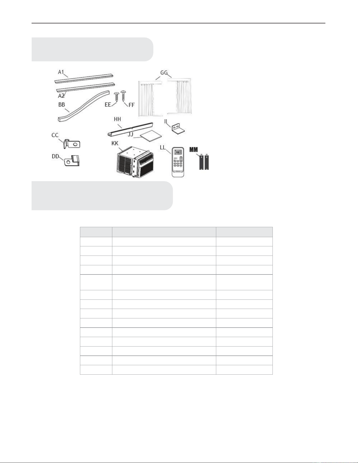
HARDWARE INCLUIDO
36
Parte
Descripción
Cantidad
A1
Sello adhesivo (gris)
1
A2
Sello adhesivo (negro)
1
BB
Sello de espuma
1
CC
Marco de seguro (para ventanas de madera)
2
DD
Marco de seguro (para ventanas con
revestimiento de vinilo)
2
EE
Tornillos de 3/8 pulg
4
FF
Tornillos 3/4 pulg
7
GG
Cortinas laterales
2
HH
Guía superior
1
II
Bloqueo de guillotina
1
JJ
Espuma EVA
2
KK
Aire acondicionado
1
LL
Control remoto
1
MM
Pilas (estándar AAA 1.5 Voltios)
2
NOTA:
Compruebe que todas las piezas estén incluidas en el
empaque.
NOTA:
Para los modelos de 12/14K Btu, el fabricante ha fijado el riel
superior (HH) y los tornillos de 3/8 de pulgadas (EE).
Ml
11
I
I I
-=+===---===t===-
-
'---
-
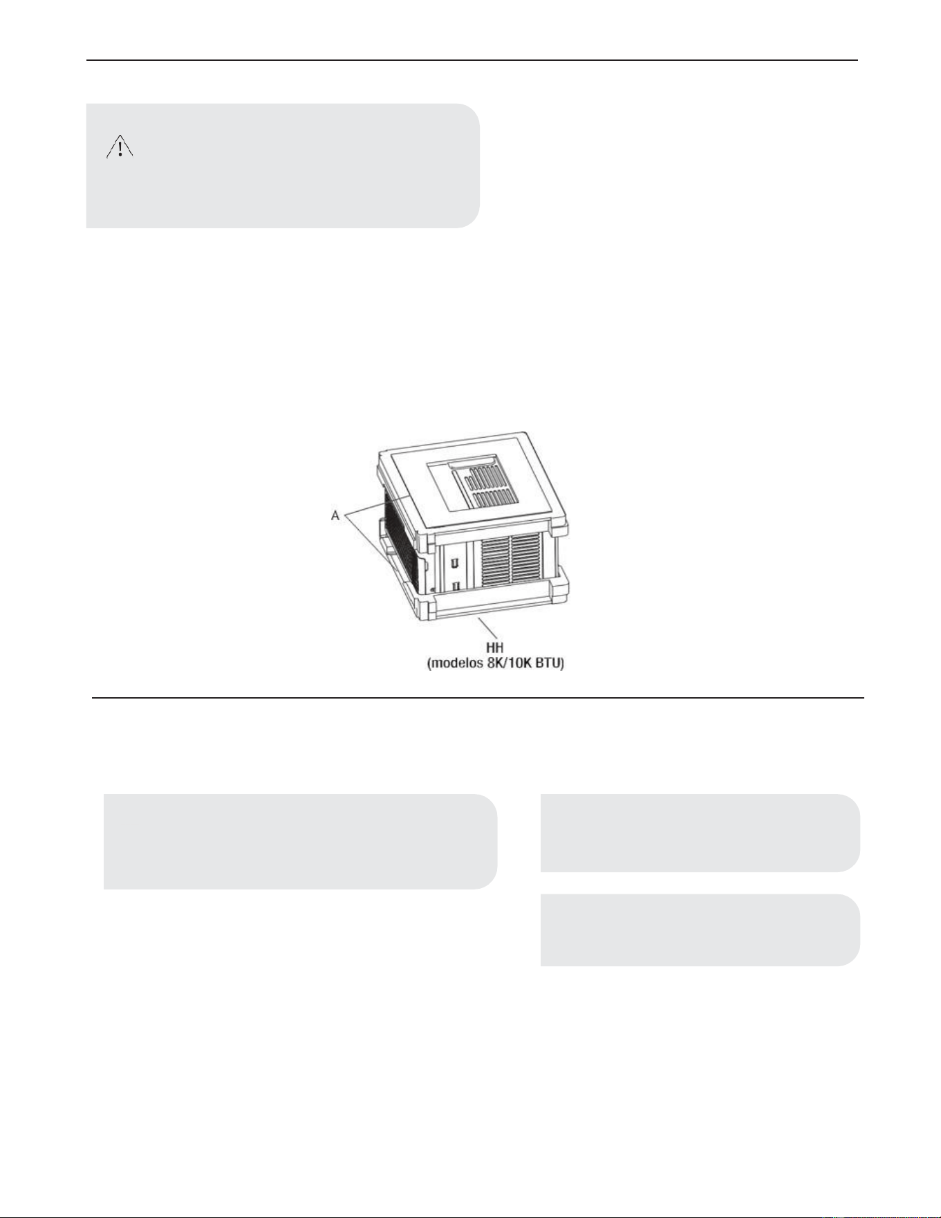
37
DESEMBALAJE DEL AIRE ACONDICIONADO
Retirada de los materiales de embalaje
• Retire y elimine/recicle los materiales de embalaje. Retire la cinta y los residuos de pegamento de las superficies antes de encender el
aire acondicionado. Frote una pequeña cantidad de jabón líquido para lavar platos en el adhesivo con los dedos. Limpie con agua
templada y séquelo.
• No utilice instrumentos afilados, ni frote alcohol, líquidos inflamables o limpiadores abrasivos para eliminar la cinta o el pegamento.
Estos productos pueden dañar la superficie del aire acondicionado.
• Manipule suavemente el aire acondicionado.
• Quite la guía superior (HH) del material de embalaje (A).
REQUISITOS DE UBICACIÓN
Antes de Comenzar
Lea completa y cuidadosamente estas instrucciones.
• Nivel de habilidad: la instalación de este aparato requiere habilidades
mecánicas básicas.
• Tiempo de finalización: alrededor de 1 hora.
• Recomendamos que dos personas instalen el producto.
WARNING:
Riesgo de exceso de peso
Se necesitan dos o más personas para mover e instalar
el aire acondicionado.
De lo contrario, podría resultar en lesiones en la
espalda o de otro tipo.
IMPORTANTE:
• Guarde estas instrucciones para uso del inspector
local.
Siga todas las normas y ordenanzas.
NOTE:
Para el instalador, asegúrese de dejar estas instruc-
ciones al consumidor.
NOTE:
Para el consumidor, guarde estas instrucciones para
referencias futuras.
A
HH
(modelos
8K/1
OK
BTU)
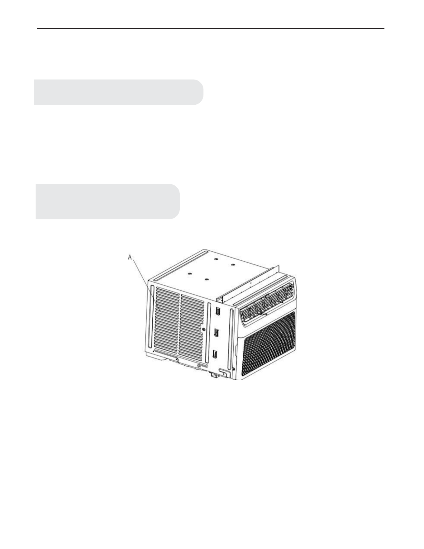
38
• La instalación correcta es responsabilidad de la persona que lo instala.
• La falla del producto debido a la instalación incorrecta no está cubierta por la garantía.
• Al momento de instalar este aire acondicionado, usted DEBE utilizar todas las piezas suministradas y seguir correctamente los
procedimientos de instalación como se describen en estas instrucciones.
Compruebe el lugar donde instalará el aire acondicionado. Es su responsabilidad que la instalación sea correcra. Asegúrese de tener todo lo
necesario para realizar una instalación correcta.
La ubicación debe brindar:
• No utilice el cable de extensión. El aparato debe instalarse de acuerdo con la normativa nacional del cableado.
• Buena ventilación del aire en la habitación a ser enfriada.
• Una abertura lo suficientemente grande para el aire acondicionado.
IMPORTANTE:
Siga todas las normas y ordenanzas.
NOTA:
No se deben obstruir las rejillas (A) del gabinete. El
aire debe pasar libremente por las rejillas del gabinete.
A
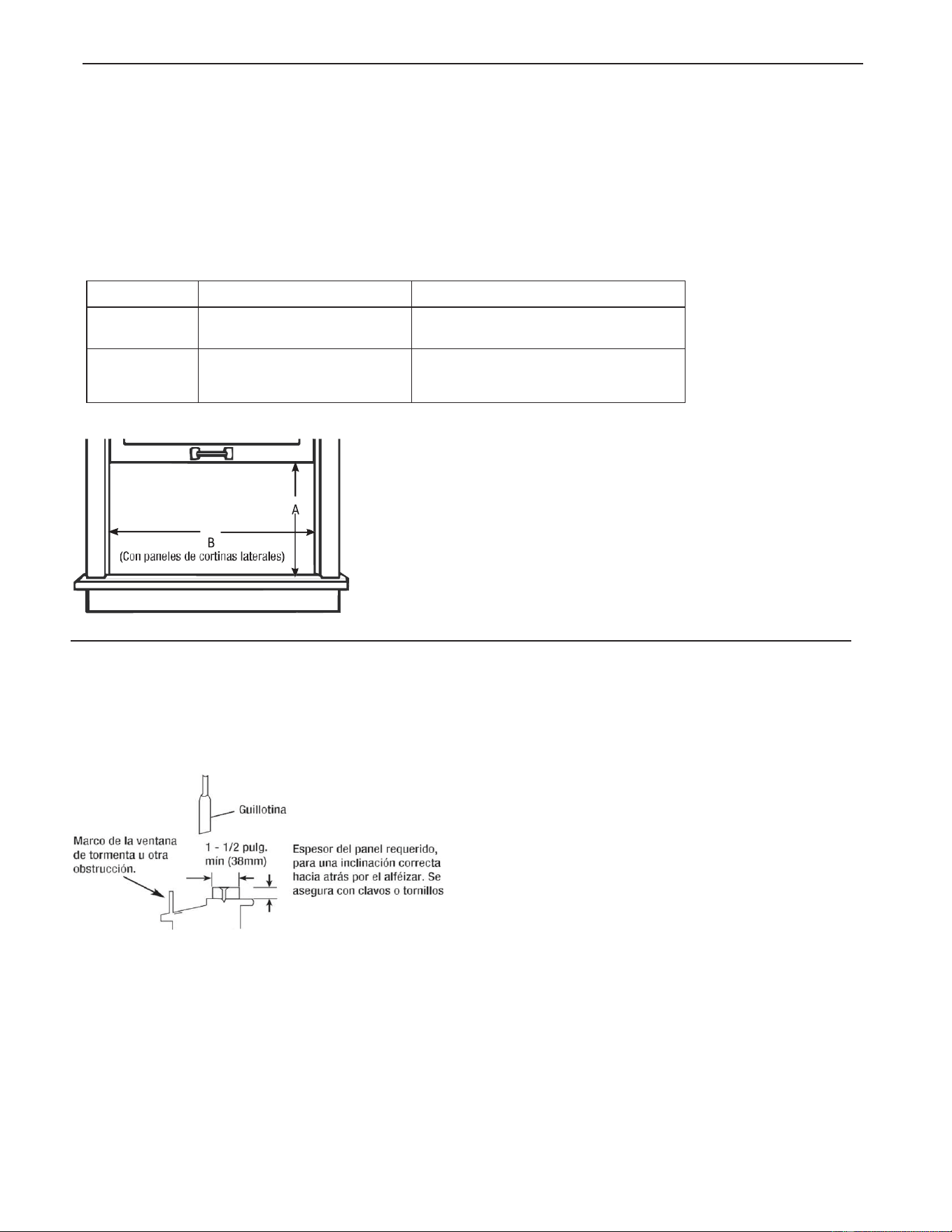
39
MEDIDAS DE APERTURA DE LA VENTANA
• Estas instrucciones son para una ventana con doble guillotina. Debe modificarlas para otro tipo de ventanas.
• Si es necesario instalarlo en una ventana estrecha, el aire acondicionado se puede instalar sin los paneles de las cortinas laterales.
Refiérase a las dimensiones de la abertura de la ventana.
• Todas las piezas de soporte deben estar aseguradas a una madera, mampostería o metal firme.
• El tomacorriente debe estar dentro del alcance del cable de alimentación.
• Siga las dimensiones de la tabla y las ilustraciones para su modelo.
Modelo
A
B
8K BTU
10K BTU
13 3/5 pulgadas (345 mm) min
24 1/2 pulgadas (622 mm) - 39 inch (991 mm)
12K BTU
14K BTU
15 1/5 pulgadas (386 mm) min
24 9/10 pulgadas (632 mm) - 39 pulgadas
(991 mm)
SI EL AIRE ACONDICIONADO ESTÁ BLOQUEADO POR LA VENTANA DE TORMENTA
Añada madera como se muestra aquí o quite la ventana antes de instalar el aire acondicionado.
Si el marco de la ventana de tormenta debe permanecer, asegúrese de que los orificios o ranuras de drenaje no estén tapados con masilla o
pintura. Se debe permitir que se drene el agua de lluvia acumulada o la condensación.
~
-
-
B
(C
on
pa
ne
les de
co
rtinas late
ral
es)
~'
"
"'";"'
Ma
r
co
de la ventana 1 _ 1 /2 p
ul
g.
de tormenta u otra min (38mm)
obstmoc;~
i
A
~
•
",,
Espesor
de
l p
ane
l requerido,
para una inclinaci6n correcta
ha
cia atr
as
po
r
el
al
fe
izar.
Se
asegura con clavos o tornillos
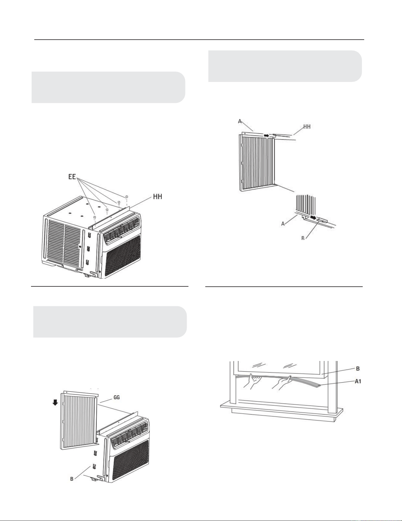
40
Instalación
1. Fijación del Riel Superior
• Encuentre la bolsa suministrada de los tornillos.
• Coloque la guía superior (HH) en la parte superior
del gabinete del aire acondicionado, alinee los 4
orificios de la parte superior del gabinete.
• Utilizando los cuatro tornillos de 3/8 de pulgada
(10mm) (EE), fije el riel superior (HH) al gabinete
del aire acondicionado.
2. Instalación de las Cortinas Laterales
• Deslice la cortina lateral (GG) directamente en el
gabinete (B).
• Deslice la cortina lateral (GG) hacia abajo.
• Inserte la parte superior y luego la parte inferior de la
carcasa de la cortina izquierda (A) en el riel superior
(HH) y en el riel inferior (B) del aire acondicionado.
• Deslice la carcasa de la cortina en los carriles tanto
como sea posible.
• Repita los paso anteriores para la cortina de la
derecha.
3. Fijación del Sello Adhesivo
• Corte el sello adhesivo (gris) (A1) al ancho de la
guillotina inferior de la ventana (B).
• Quite el reverso del sello y fije el sello a la parte de
abajo de la guillotina inferior de la ventana.
NOTA:
Fije las cortinas al aire acondicionado antes de colocar
el aire acondicionado en la ventana.
NOTA:
Para algunos modelos, el riel superior ha sido fijado
por el fabricante.
NOTA:
Fije las cortinas al aire acondicionado antes de colocar
el aire acondicionado en la ventana.
HH
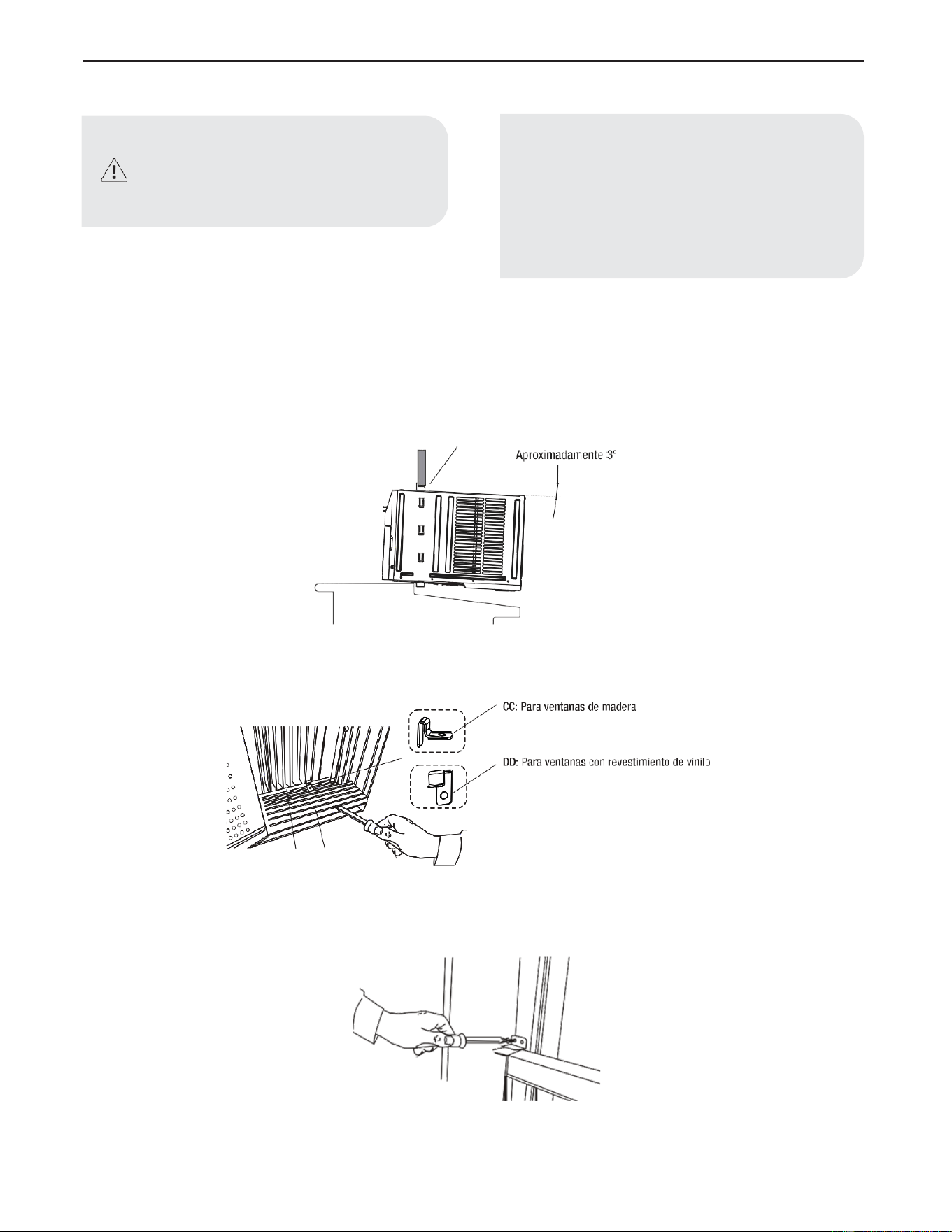
41
4. Colocación del Aire Acondicionado en la Ventana
• Centre el aire acondicionado en la ventana. Baje la guillotina de la ventana detrás del riel superior (HH) para mantener el gabinete en su
lugar.
• Sostenga firmemente el aire acondicionado; coloque cuidadosamente la unidad en la abertura de la ventana de tal manera que la parte
inferior del marco del aire acondicionado quede contra el alféizar de la ventana y asegúrese de que la unidad quede centrada en la
ventana.
• Cierre cuidadosamente la ventana detrás del riel superior de la unidad.
• Coloque el bloqueo del marco (CC) o (DD) entre la carcasa de la cortina (A) y el alféizar de la ventana (B) con un tornillo de 3/4 de
pulgada (19mm) (FF) como se muestra.
• Para asegurar la guillotina inferior en su lugar, fije el bloqueo de la guillotina (II) utilizando el tornillo 3/4 de pulgada (19mm) (FF)
como se muestra.
ADVERTENCIA:
• Se necesitan dos o más personas para mover e
instalar el aire acondicionado.
•
De lo contrario, podría resultar en lesiones en la
espalda o de otro tipo.
NOTE:
• Manipule el aire acondicionado con cuidado.
• Asegúrese de que el aire acondicionado no se
caiga durante la instalación o la extracción.
• No bloquee las rejillas del panel frontal.
• No bloquee las rejillas de la parte exterior del aire
acondicionado.
• Su modelo puede diferir del que se muestra aquí.
HH
A
B
(L
/
CC:
Para
v
entana
s de
madera
1,
~ ·
______
.,,
,,-t::ri-',
/
DD:
Para
ventanas
c
l ~
,-{'
'"re,estimieotode,ioilo
______
.,.,
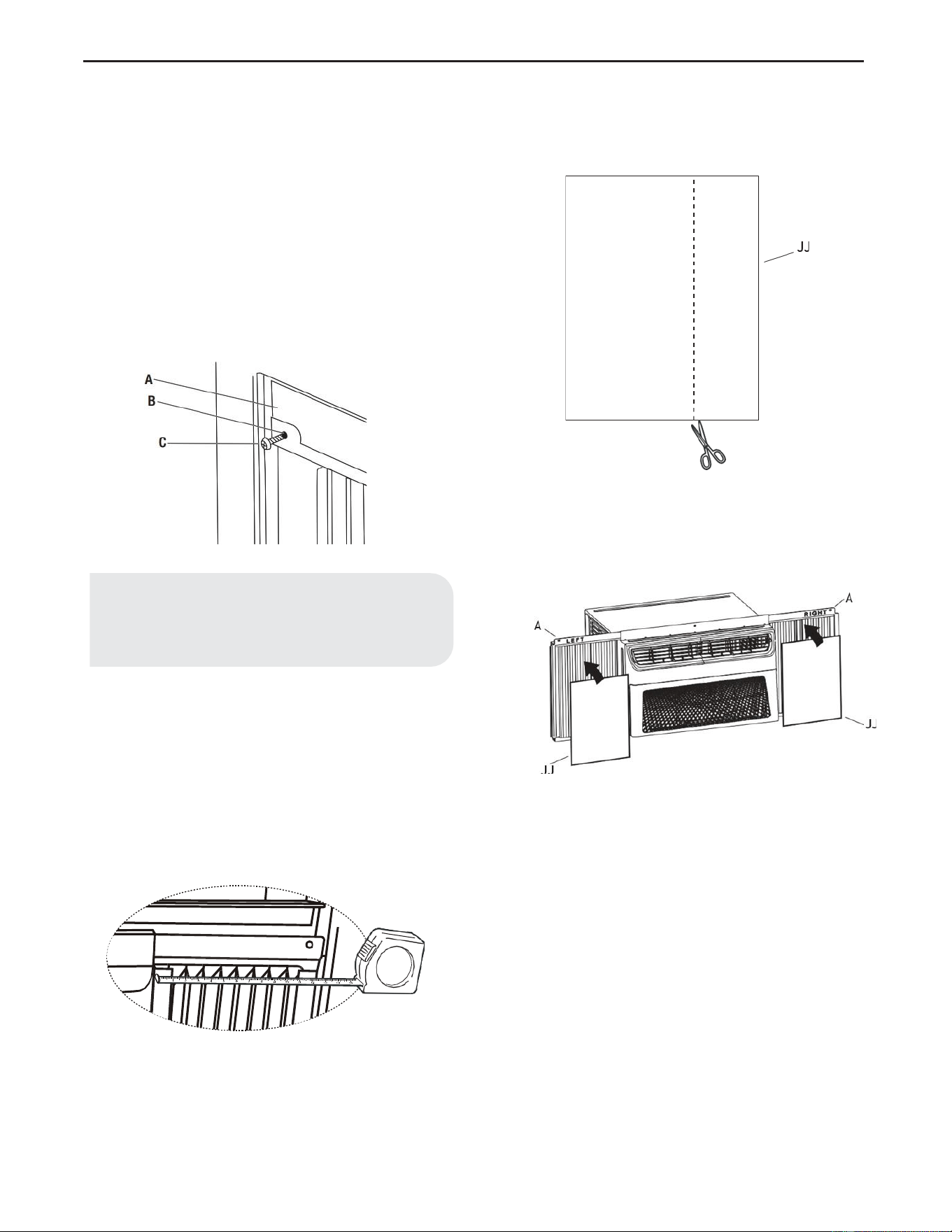
42
5. Fijación de las Cortinas Laterales a la Ventana
• Saque la cortina de la izquierda de la unidad y
adáptela al canal de la ventana.
• Utilice la broca de 1/8 de pulgada (3mm) para
perforar un orificio a través del orificio en la
carcasa de la cortina (B).
• Coloque uno de los tornillos de 3/4 de pulgada
(19mm) (C) a través de la carcasa de la cortina de
la izquierda (B) y en la guillotina de la ventana
(A).
• Repita para la cortina derecha.
• Coloque una espuma EVA (JJ) en la carcasa de la
cortina.
• Para minimizar la fugas de aire y garantizar un
aislamiento óptimo, si es necesario, instale la
Espuma EVA (JJ) en la carcasa de la cortina.
• Después de instalar la unidad en la ventana, mida
el ancho interno de la cortina lateral como se
muestra.
• Marque una línea en la espuma EVA (JJ) a 1/8
pulgadas (3mm) menos que el ancho medido;
luego, corte la espuma EVA (JJ) por la línea.
• Quite el reverso de la espuma EVA (JJ). Fije la
espuma EVA (|JJ) a la carcasa de la cortina (A), el
lado con el adhesivo debería estar frente a la
carcasa de la cortina.
• Repita para la cortina izquierda.
NOTA:
Los pasos restantes en esta página son solo para los
modelos E- star, con el LOGO E- star en el panel de
control.
A
B
Jj
,__----'
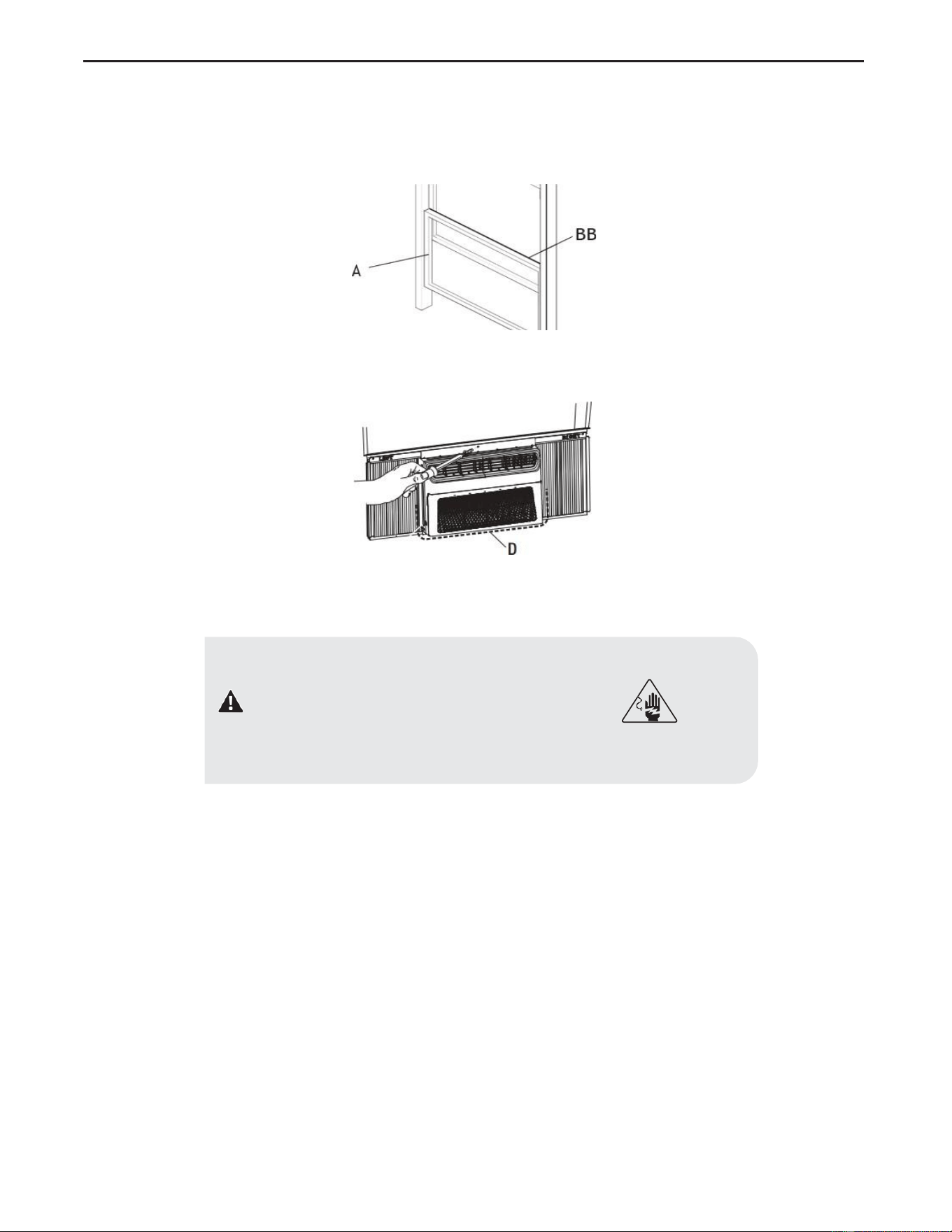
43
6. Finalización de la instalación
• Coloque el sello de espuma (BB) detrás de la parte superior de la guillotina inferior de la ventana (A) y contra el vidrio de la ventana
superior.
• Utilice la broca de 1/8 de pulgada (3mm) para perforar un orificio a través del orificio en el riel superior.
• Fije el riel superior al marco de la ventana con un tornillo de 3/4 de pulgada (19mm) para asegurar la ventana en su lugar.
• Compruebe el espacio (D) alrededor de la unidad y séllelo con el sello adhesivo (negro) (A2) adjunto.
• Conéctelo a una toma con 3 clavijas con conexión a tierra.
• Presione RESET en el cable de alimentación. Consulte “Requisitos Eléctricos”.
PELIGRO: PELIGRO DE DESCARGA ELÉCTRICA
• Conéctelo a una toma con 3 clavijas con conexión a tierra.
• Presione RESET en el cable de alimentación. Consulte
“Requisitos Eléctricos”.
A
A
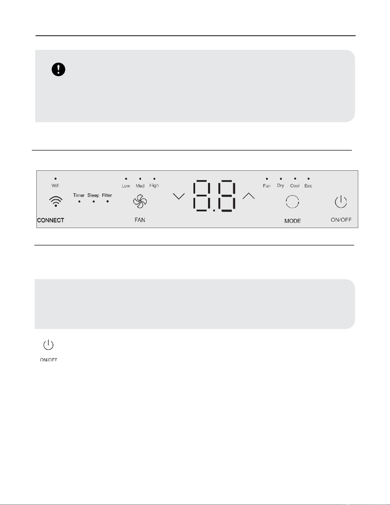
44
Operación
• Utilizar el aire acondicionado le ayudará a obtener los mejores resultados posibles.
• Esta sección explica el uso adecuado del aire acondicionado.
1. Uso del Panel de Control
CONFIGURACIÓN DE ON/OFF
Presione el botón power para encender el aire acondicionado.
• Seleccione el modo. Consulte “Configuración de Modo” en la página 15.
• Ajuste la temperatura. Consulte “Configuración de Temperatura” en la página 15.
• Seleccione la velocidad del ventilador. Consulte “Velocidad del Ventilador” en la página 15.
IMPORTANTE:
• Si apaga el aire acondicionado, espere al menos 3 minutos antes de volver a encenderlo. Esto evita que el aire
acondicionado queme un fusible o haga saltar el disyuntor.
• Mejores límites para aires acondicionados que funcionan en modo COOL o DRY: Exterior 64,4-109,4°F (18-43°C), ≤
80% RH; interior 62,6-89,6°F (17-32°C), ≤ 80% RH.
• Mejores límites para aires acondicionados que funcionan en modo de Calefacción: Exterior 19,4-75,2°F (-7-24°C), ≤
80% RH; interior 32-80,6°F (0-27°C), ≤ 80% RH.
NOTA:
Cuando se enciende el aire acondicionado por primera vez después de conectarlo, la pantalla mostrará la temperatura establecida
actual y funcionará en ECO.
Después de realizar la limpieza y volver a conectar el filtro, presione el botón POWER para reinciar, la luz del FILTRO se apagará.
8
•
• • • • •
•
•
- -
Wi
fi
Low
Med
Hi
gh
I I I I
F
an
D
ry
Cool
Eco
G--
Ti
mer Sleep Filter
~
V
-
-
A
0
(0
-
• •
•
I I
I I
•
-
■
-
CONNECT
FAN
MODE
ON/OFF
ON
/OFF
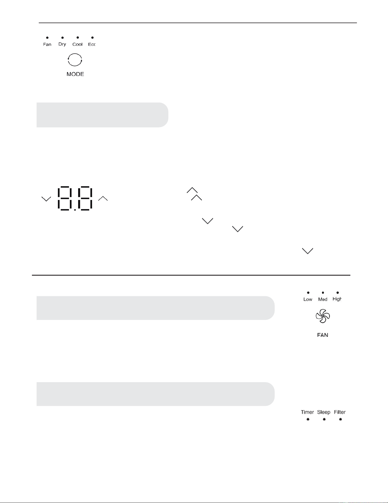
45
CONFIGURACIÓN DE MODO
• Presione MODE repetidamente hasta que vea que la luz indicadora brille en la configuración
deseada.
• Seleccione FAN (ventilador), DRY (seco), COOL (Frío), Eco.
• FAN - Para seleccionar el modo Solo Ventilador.
• DRY - Seca el ambiente. El aire acondicionado selecciona automáticamente la temperatura. El
ventilador funciona solo a baja velocidad.
• COOL - Enfría la habitación.
• ECO - Enfría la habitación y ahorra energía.
• En el modo ECO, el ventilador seguirá funcionando después de que el compresor se apague durante 2 minutos (4 minutos para la
primera vez), luego el ventilador se apagará durante 10 minutos. A continuación, el ventilador realiza ciclos de 2 minutos de encendi-
do y 10 minutos de apagado hasta que la temperatura de la habitación esté por encima de la temperatura ajustada, en este momento, el
compresor se vuelve a encender y reanuda el Enfriamento. Seleccione el modo ECO para iniciar esta función.
CONFIGURACIÓN DE TEMPERATURA
Presione el botón más UP para aumentar la temperatura. Cada vez que presione o mantenga
presionado el botón más UP , la temperatura aumentará de a un 1°F (1°C) hasta llegar a los
86°F (30°C).
Presione el botón menos DOWN para disminuir la temperatura. Cada vez que presione o
mantenga presionado el botón menos DOWN , la temperatura disminuirá de a un 1°F (1°C)
hasta llegar a los 61°F (16°C)
Para cambiar la temperatura de °F a °C: Presione los botones MODE y DOWN
al mismo
tiempo durante 5 segundos para cambiar de °F a °C.
VELOCIDAD DEL VENTILADOR
• Presione FAN hasta que vea que la luz indicadora brille en la configuración deseada.
• Seleccione High (Alta), Med (Media), Low (Baja).
• Alta - para una máxima refrigeración.
• Media - para una refrigeración normal.
• Baja - para una refrigeración leve.
FUNCIONES DE TEMPORIZADOR, SUSPENSIÓN, FILTRO
• La luz LED en el panel de control para Temporizador, Suspen-
sión, Filtro.
• Para el funcionamiento de las funciones, consulte “Uso del
control Remoto”.
NOTA:
El modo Dry no debe utilizarse para enfriar la sala.
NOTA:
El botón Fan funcionará solo cuando se hayan elegido los modos Cool, Fan, ECO o Heat.
NOTE:
En el modo ECO, el ventilador funcionará a una baja velocidad cuando el compresor de apague.
• • • •
Fan
Ory
Cool
Ec
o
0
MOD
E
V
V
V
V
• • •
Low
Med
High
FAN
Ti
mer Sleep
Fi
lter
• • •
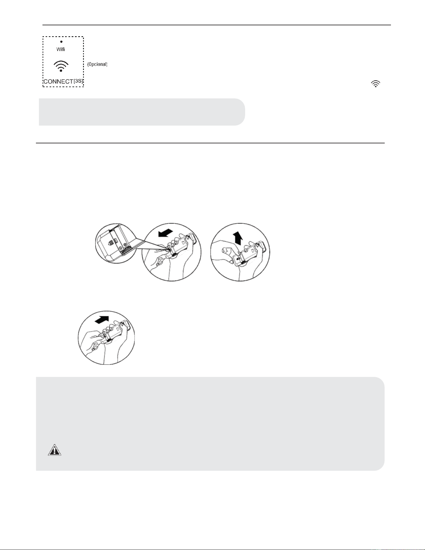
46
2. Uso de Control Remoto
WI-FI
• El control WI-FI está disponible para los modelos conectados con este logo en el panel de control.
• Presione el botón CONNECT “ ” durante 3 segundos; la luz LED comenzará a parpadear.
• Después de que el WI-FI se conecta al enrutador, el LED se mantiene encendido o el LED se
mantiene apagado.
COLOCACIÓN DE LAS PILAS
• Retire la tapa de las pilas en la dirección de la flecha.
• Inserte pilas nuevas asegurándose de que las marcas (+) y (-) de las pilas coincidan.
• Vuelva a colocar la tapa volviendo a deslizarla en su posición.
NOTE:
El control WI-FI solo está disponible para los modelos con control WI-FI-
NOTA:
• Utilice 2 pilas AAA estándar (1,5 voltios). No utilice pilas recargables.
• Sustituya las pilas por unas nuevas del mismo tipo cuando la pantalla se atenúe o al cabo de 6 meses.
• Al reemplazar las pilas, siempre reemplace ambas pilas con las nuevas. No mezcla pilas viejas y nuevas. No mezcle
pilas alcalinas, estándar (carbono-zinc) ni recargable (ni-cd, ni-mh, etc).
• Si no se utiliza el aire acondicionado durante un periodo de tiempo prolongado, retire las pilas del control remoto.
• No utilice el control remoto si las pilas tienen fugas.
• Los productos químicos de las pilas podrían causar quemaduras u otros peligros para la salud.
• No tire las pilas al fuego. Las pilas pueden explotar o tener fugas.
•
Wifi
~
(Opciona
l)
-
•
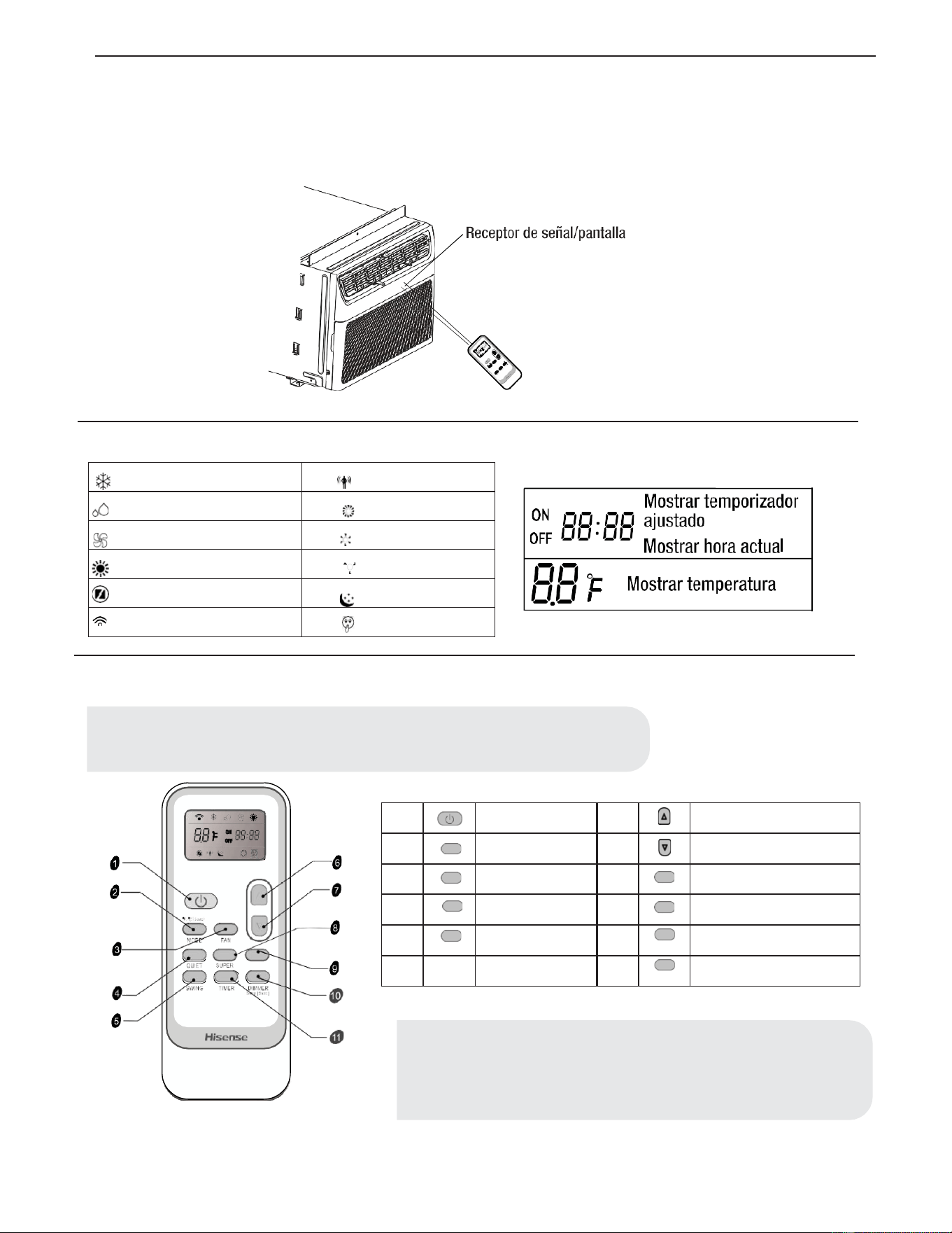
47
COMO UTILIZARLO
• Para operar el aire acondicionado, dirija el control remoto a la señal del receptor. El control remoto operará el aire acondicionado a
una distancia de hasta 23´ (7m) cuando apunte al receptor de señal del aire acondicionado.
SÍMBOLOS DE INDICACIÓN
BUTTON AND FUNCTION
1
ON/ OFF
6
ARRIBA
2
°F/°C [ 5 SEC]
MODE
MODO
7
ABAJO
3
FAN
VENTILADOR
8
SUPER
SÚPER
4
QUIET
QUIET (SILENCIO)
9
FILTER
FILTRO
5
SWING
OSCILACIÓN
10
DIMMER
Sleep [ 5 sec]
ATENUADOR o SUSPENSIÓN
11
TIMER
TEMPORIZADOR ON/OFF
FILTER
NOTA:
Mantenga presionado el botón MODE en el control remoto durante 5 segundos
para cambiar la visualización de la temperatura de grados Fahrenheit (°F) a
grados Celsius (°C).
Indicador de refrigeración
Eco indicator
Indicador de seco
High fan speed
Indicador de solo ventilador
Medium fan speed
Indicador de calentamiento
Low fan speed
Indicador de SUPER
Sleep indicator
Signal transmit
Quiet indicator
NOTA:
El control remoto puede tener un aspecto diferente. La función giratoria no está disponible en
esre modelo.
Receptor
de
seiial/pantalla
*
«t~
cf)
:·~
·~
~
,,
~
..
~
...
·,·
0
Mostrar
temporizador
N ,:,,:,.
00
ajustado
OFF
CICI
•
CIC/
Mostrar
hora
actual
~
~
~
• >
@
~
BB
°f
Mostrar
temperatura
~
f
-=-
,,
•
@
~
881=
:
asBB
• • '-
oe
(!)
C)
Cl
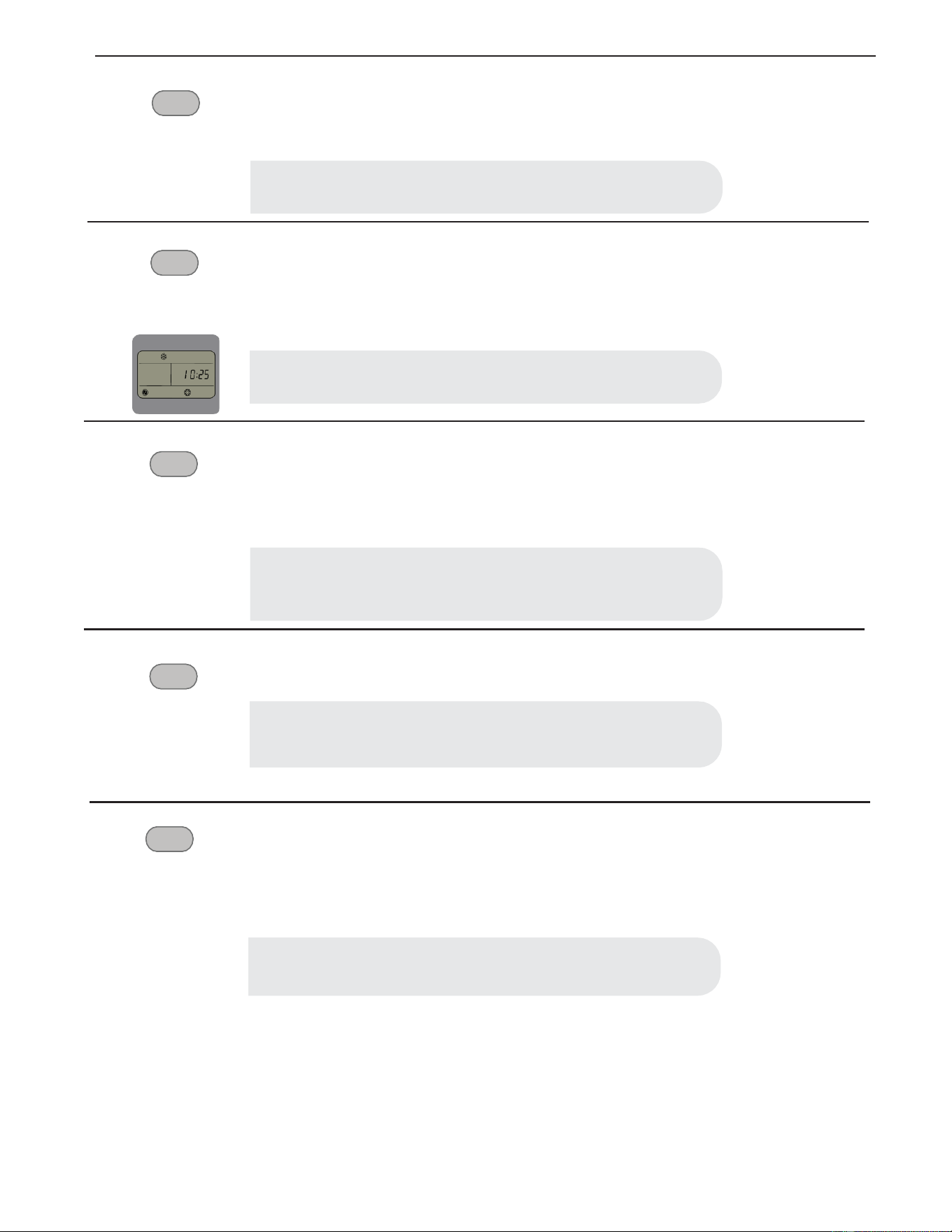
48
QUIET
SILENCIO
• Presione el botón QUIET para configurar o cancelar la operación del Modo Silencio
SUPER
Enfriamento rápido
FILTER
SÚPER
El botón SUPER se utiliza para iniciar o detener el enfriamento rápido.
• Presione el botón SUPER. El aire acondicionado ajusta automáticamente la velocidad del ventilador en
Alta y la temperatura en 16°C.
• Para apagar el control Super, presione MODE, FAN, QUIET o SUPER botón del control remoto.
FILTRO
• Cuando la luz indicadora del filtro está encendida, quite, limpie y reemplace el filtro de aire. Consulte
“Limpieza del Filtro de Aire”.
• Presione el botón Power en la máquina o el botón FILTER en el control remoto para reiniciar el filtro
después de realizar la limpieza y el cambio del filtro del aire.
DIMMER
Sleep (5 sec)
ATENUADOR
• Presione el botón DIMMER para apagar la pantalla del panel de control.
DIMMER
Sleep (5 sec)
SUSPENSIÓN
El modo SUSPENSIÓN puede ajustarse en modo Enfriamento, Calentamiento o ECO. En modo de suspen-
sión, la unidad utilizará velocidades de ventilador más bajas y silenciosas y ajustes de temperatura automáti-
cos que ofrecen 8 horas de condiciones óptimas para suspender antes de apagarse.
• Presione MODE para seleccionar Cool, Dry o ECO.
• Presione el botón arriba o abajo para establecer la temperatura.
• Mantenga presionado el botón DIMMER del control remoto durante 5 segundos para cambiar el modo
ATENUADOR al modo SUSPENSIÓN.
• Al cabo de 10 segundos, la luz del panel de control se atenuarán.
NOTA:
Toma cerca de 2 a 3 minutos para ingresar al modo de silencio.
NOTA:
Cuando la luz está encendida, permanecerá encendida por 180 horas o hasta
que usted presione el botón Clean Filter.
NOTA:
El control de suspensión no se puede seleccionar en el modo Ventilador.
NOTA:
En el modo SUPER, puede configurar el temporizador.
NOTA:
En el modo ATENUADOR, los nuevos ingresos del control volverán la
pantalla a normal.
C)
C)
C)
C)
C)
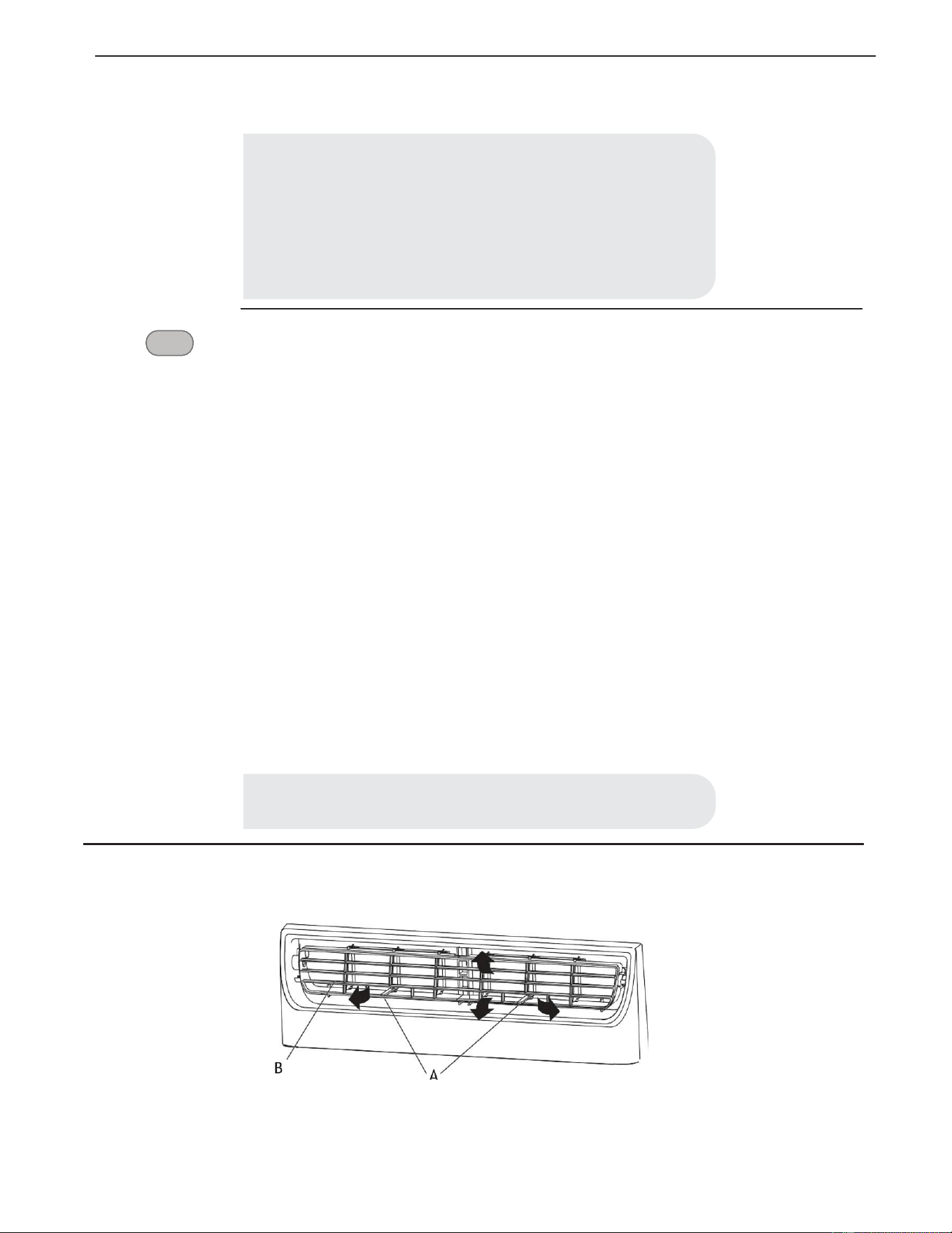
49
• Para desactivar el control de Suspensión, presione MODE, FAN, SLEEP o espere 8 horas para que el
control de Suspensión se desactive automáticamente.
TIMER
TEMPORIZADOR
Configuración del Aire Acondicionado para que se encienda:
• Enchufe el aire acondicionado y utilice el control remoto para encenderlo.
• Utilice el control remoto para configurar el modo deseado, la temperatura, la velocidad del ventilador,
etc.
• Utilice el control remoto para apagar el aire acondicionado.
• Presione TIMER en el control remoto y utilice los botones UP, DOWN para establecer el tiempo de
retraso deseado hasta que se ENCIENDA el aire acondicionado. El tiempo de retraso se puede configurar
de 0 a 24 horas en incrementos de una hora.
• Presione TIMER de nuevo para introducir el tiempo de retraso. EI LED TIMER del aire acondicionado
se ilumina y el tiempo de retraso aparece en el control remoto.
Configuración del Aire Acondicionado para que se APAGUE:
• Enchunfe el aire acondicionado y utilice el control remoto para encenderlo.
• Utilice el control remoto para configurar el modo deseado, la temperatura, la velocidad del ventilador,
etc.
• Presione TIMER en el control remoto y utilice los botones, UP, DOWN para establecer el tiempo de
retraso deseado hasta que se ENCIENDA el aire acondicionado. El tiempo de retraso se puede configurar
de 0 a 24 horas en incrementos de una hora.
• Presione TIMER de nuevo para introducir el tiempo de retraso}. EI LED TIMER del aire acondicionado
se ilumina y el tiempo de retraso aparece en el control remoto.
Para cancelar el TIMER:
• Presione el botón TIMER de nuevo; cuanso se escucha un “Beep” y el indicador desaparece, el
modo TIMER ha sido cancelado.
3. Cambio en la Dirección del Aire
• Utilice el Aspa de Nivel Vertical (A) para dirigir el aire hacia la izquierda o la derecha. Utilice todo el cartucho (B) para dirigir el aire
hacia arriba, abajo o adelante.
NOTA:
La función TIMER solo puede configurarse con el control remoto.
NOTA:
Cuando presiona el botón sleep:
• El aparato dejará de funcionar automáticamente después de funcionar
durante 8 horas.
• La velocidad del ventilador se ajusta automáticamente a velocidad baja.
• En los modos Enfriamento, Secado y ECO, la temperatura establecida
aumentará a 4°F (2°C) como máximo durante 2 horas y continuará
funcionando a esa temperatura hasta qye el auto se apague.
C)
'!
I
C
~·
.JJ.
-Ii
i
l~~
_L
-
--
/ -- -
_/
,
I
i
/
I
B A
/
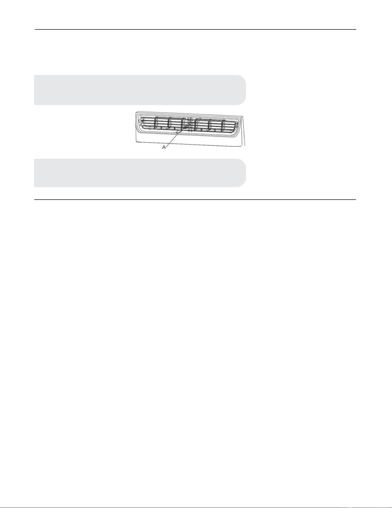
50
4. Ventilación del Aire de Escape
• Abra el control de la ventilación del aire de escape para abrir la ventilación de escape y sacar el aire viciado o el humo de la habitación.
• Presione el control de la ventilación del aire de escape para cerrar la ventilación de escape para una máxima y continua refrigeración.
5. Sonidos Normales
Cuando el aire acondicionado funcione con normalidad, es posible que escuche sonidos como:
• Gotas de agua golpeando el condensador, causando un sonido de clic o un tintineo. Las gotas de agua ayudan a enfriar el condensador.
• El movimiento del aire desde el ventilador.
• Chasquidos del ciclo del termostato.
• Vibraciones o ruido por una mala construcción de la pared o la ventana.
• Un zumbido agudo o un ruido de pulsación debido al encendido y apagado cíclico del compresor.
NOTA:
• El control de la ventilación del aire de escape está solo disponible en los
modelos 12k/14k.
NOTE:
El control de ventilación del aire de escape funciona solamente cuando el
ventilador está funcionando.
I
/
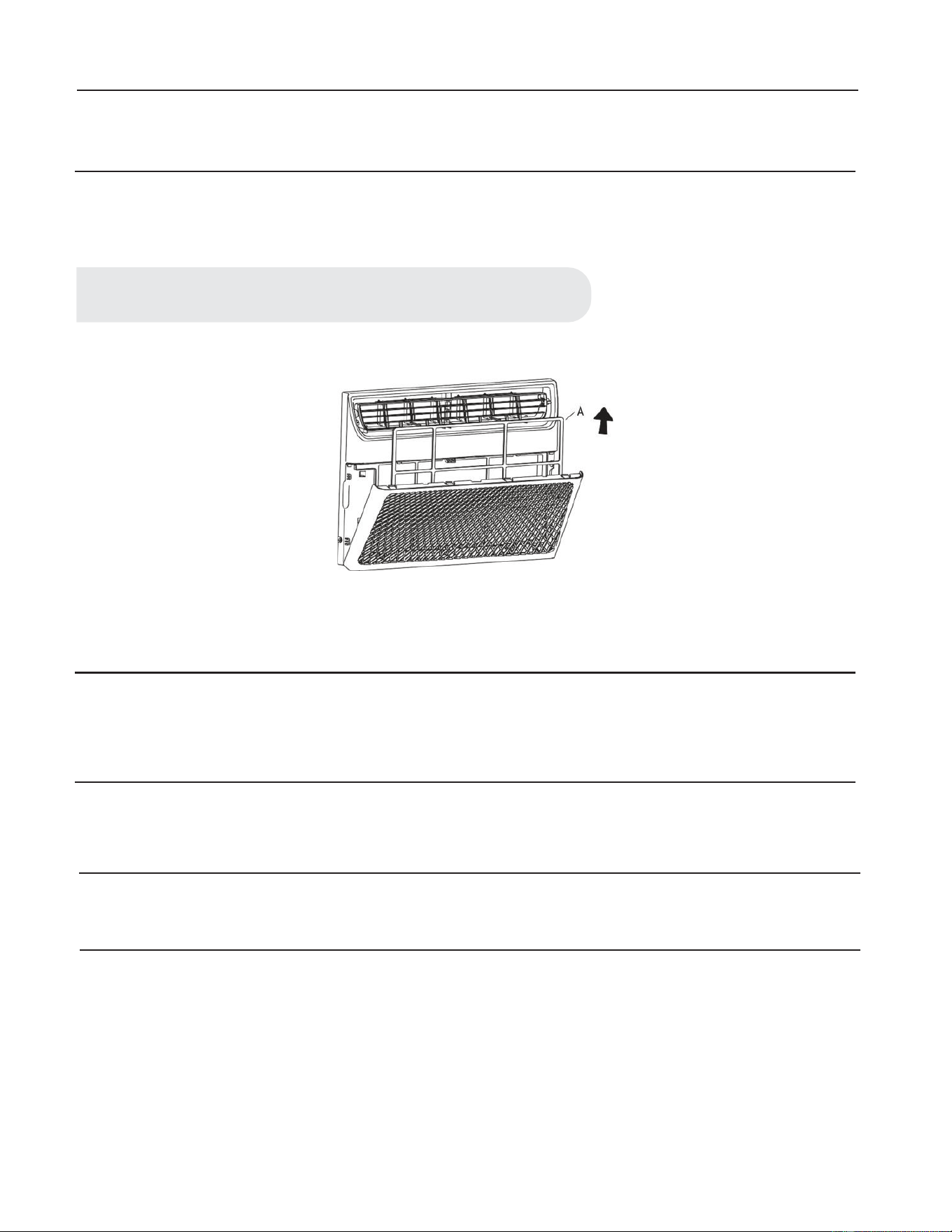
51
Limpieza y Cuidado
Su aire acondicionado nuevo está diseñado para brindarle muchos años de servicio confiable. Esta sección le dice cómo limpiar y cuidar su
aire acondicionado correctamente. Llame a su vendedor local autorizado para realizar el control anual. Recuerde que el costo de la llamada
del servicio corre por su cuenta.
LIMPIEZA DEL FILTRO DE AIRE
Es posible extraer el filtro de aire para limpiarlo fácilmente. Un filtro limpio ayuda a remover el polvo, las pelusas y otras partículas del aire
y es importante para una mejor refrigeración y funcionamiento eficiente. Compruebe el filtro cada 2 semanas para ver si necesita una
limpieza.
• Apague el aire acondicionado.
• Abra el panel frontal. Agarre el filtro por la manija y quítelo.
• Utilice una aspiradora para limpiar el filtro del aire. Si el filtro está muy sucio, lávelo con agua tibia y detergente suave. No lave el
filtro del aire con detergente para vajillas ni utilice limpiadores químicos. Deje que el filtro se seque completamente al aire antes de
volver a colocarlo para garantizar la máxima eficacia.
• Vuelva a colocar el filtro de aire en el aire acondicionado.
LIMPIEZA DEL PANEL FRONTAL
• Apague el aire acondicionado.
• Limpie el panel frontal con un paño húmedo y suave.
• Deje secar completamente el panel frontal.
REPARACIÓN DE LA PINTURA DAÑADA
Compruebe una o dos veces al año si hay daños en la pintura. Esto es muy importante, especialmente en áreas cerca de océanos o donde
haya problemas de oxidación. Si es necesario, retoque con una pintura de esmalte de buena calidad.
MANTENIMIENTO ANUAL
Su aire acondicionado necesita mantenimiento anual para garantizar un rendimiento estable y superior durante el año. Llame a su vendedor
local autorizado para programar el control anual. El costo de la inspección anual corre por su responsabilidad.
EXTRACCIÓN DEL AIRE ACONDICIONADO DE LA VENTANA
• Apague el aire acondicionado y desconecte el cable de alimentación.
• Quite el sello de la guillotina entre las ventanas y desatornille el seguro.
• Quite los tornillos instalados en el marco y en el seguro. Quite la espuma EVA (solo en los modelos E-star).
• Cierre la carcasa de la cortina.
• Sostenga firmemente el aire acondicionado, levante la guillotina y retírela cuidadosamente.
• Tenga cuidado de no derramar agua mientras levantan la unidad de la ventana. Guarde las piezas junto con el aire acondicionado.
NOTA:
No opere el aire acondicionado sin el filtro en su lugar.
52
Resolución de problemas
Problema
El aire acondicionado no funciona
• El cable eléctrico está desenchufado. Conételo a una toma con 3 clavijas con conexión a tierra. Consulte “Requisitos Eléctricos”.
• El cable de alimentación salta (el botón RESET salta). Presione y suelte RESET para reanudar la operación.
• Se quemó un fusible o el disyuntor saltó. Reemplace el fusible o restablezca el interruptor. Si el problema persiste, llame a un
electricista. Consulte “Requisitos Eléctricos”.
• No se ha presionado el botón Power. Presione el botón Power.
• Ha habido un fallo eléctrico local. Espere a que se restaure la alimentación.
Problema
El aire acondicionado hace que salten los fusibles o se dispare el interruptor.
• Se están utilizando demasiados aparatos en el mismo circuito. Desenchufe o reubique los aparatos que compartan el mismo circuito.
• Se utiliza un fusible de retardo o el interruptor de una capacidad incorrecta. Reemplácelo por un fusible de retardo o el interruptor de
la capacidad correcta. Consulte “Requisitos Eléctricos”.
• Se utiliza un cable de extensión. No utilice un cable de extensión con este u otro aparato.
• Está tratando de reiniciar el aire acondicionado demasiado rápido después de haberlo apagado. Espere al menos 3 minutos después de
apagar el aire acondicionado antes de intentar reiniciarlo.
Problema
El cable de alimentación del aire acondicionado salta (el botón Reset salta).
• Las alteraciones en la corriente eléctrica pueden hacer saltar (el botón RESET saltará) el cable de alimentación. Presione y suelte
RESET para reanudar la operación.
• La sobrecarga eléctrica, el sobrecalentamiento, el cable apretado o uno viejo pueden hacer saltar (el botón RESET saltará) el cable de
alimentación. Después de corregir el problema, presione y suelte RESET para reanudar la operación.
Solución
PELIGRO: PELIGRO DE DESCARGA ELÉCTRICA
• Conéctelo a una toma con 3 clavijas con conexión a tierra.
• No quite la terminal a tierra.
• No utilice el adaptador.
• No utilice el cable de extensión.
• Pueden producirse incendios, descargas eléctricas o la muerte si no se siguen estas
instrucciones.
Solución
Solución
NOTA:
Se debe reemplazar el cable de alimentación dañado por un cable nuevo que se obtiene del
fabricante, no se debe reparar.
A

53
Problema
Air conditioner seems to run too much.
• El aire acondicionado actual ha reemplazado un modelo antiguo. El uso de componentes más eficientes podría provocar que el aire
acondicionado funcione más tiempo que un modelo antiguo, pero que el consumo energético total sea inferior. Los aires acondiciona-
dos más nuevos no emiten la “ráfaga” de aire frío a la que puede estar acostumbrado por los aires acondicionados viejos, pero esto no
indica menos capacidad de enfriado o eficiencia. Consulte el coeficiente de eficiencia energética (EER) y la calificación de capacidad
(en Btu/h) marcados en el aire acondicionado.
• El aire acondicionado se encuenrra en una sala muy ocupada, o se están utilizando aparatos que producen calor en la sala. Utilice
ventiladores de extracción mientras cocine o se bañe y no utilice aparatos que produzcan calor durante la horas más cálidas del día. Es
posible que sea necesaria una mayor capacidad del aire acondicionado, según el tamaño de la sala a enfriar.
Problema
El aire acondicionado que se apaga y se enciende con frecuencia o no enfría.
• El aire acondicionado no tiene un tamaño adecuado para la sala. Compruebe las capacidades de enfriado de su aire acondicionado.
Los aires acondicionados no están diseñados para refrigerar múltiples habitaciones.
• El filtro está sucio u obstruido por residuos. Limpie el filtro. Las bobinas del evaporador interno y del condensador externo están
sucias u obstruidas por residuos. Consulte Mantenimiento Anual.
• Hay calor o humedad excesiva (cocinas abiertas, duchas, etc.) en la habitación. Utilice un ventilador para extraer el calor o la
humedad de la sala. Intente no utilizar aparatos que produzcan calor durante las horas más cálidas del día.
• Las rejillas están bloqueadas. Instale el aire acondicionado en un lugar donde las rejillas no estén obstruidas por cortinas, persianas,
muebles, etc.
• La temperatura de la habitación que está intentando enfriar es extremadamente calurosa. Permita más tiempo para que el aire
acondicionado enfríe la habitación calurosa.
• Las ventanas o las puertas están abiertas. Cierre las ventanas y las puertas.
• El control de temperatura no está en una configuración lo suficientemente fría. Modifique el control de temperatura a un ajuste más
frío al presionar el botón menos para reducir la temperatura. Establezca el control de la velocidad del ventilador a un ajuste más alto.
Problema
Caen gotas de agua desde el gabinete en su hogar
• El aire aondicionado no está correctamente nivelado. El aire acondicionado debería inclinarse un poco hacia afuera. Nivele el aire
acondicionado para brindar la inclinación hacia afuera y garantizar un drenaje correcto. Consulte instrucciones de instalación.
Solución
Solución
Solución
NOTA:
No perfore la parte inferior de la base de metal ni la bandeja de condensado.
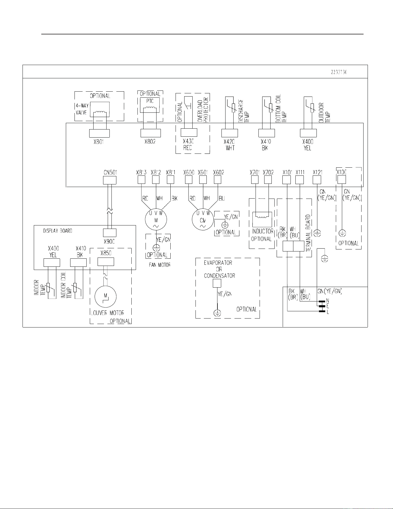
54
Diagrama de circuito
DIS
P
LAY
B
OARD
X400
Y
EL
1 O
PTION
AL
7
X80
1
I
_J
:~
I~
IL
OUV
ER
M
OTOR
L -
_QpTIONAlJ
-
_J
X802
~TI
ONA
1.J
F
AN
M
OTOR
2233
1
30
,--J
_J
w
0
_J
o o
c..:,
u
O::'.
l
<C
<C
>-1
O::'.
:z
OU
<C
:::;;;
0
0
-'W
::r::
(l_
0
0
-
O:::>-
f-(l_
on_
I§;
w o l
U:::;,;
>-:::;;;
>-:::;;;
>0:::
~ w O
LLJ
=,
LLJ
O
n_
Cl>-
CO>-
0>-
I
I
X430
I
X420
X
410
X400
L
RED
- J
WH
T
BK Y
EL
7
I
o l
2§
1
I
WH
co
I
'....L.:
I
<i!
I
.,.
(BU)
:z
I
O;TIO
NA
L I
~I
w
L _
_J
BK
OPTIONAL
(BR
[_JI,.............,
J
1 E
VA
PORATOR
- - 7
I
COND~~SA
TOR
I
: !
E/G
N :
I I
L -
~
-
~T
I
ON
AJ
BK
WH
GN(YE/GN)
(BR)
L..
( B
---'
U )
-----tt•
N
E
L------L