
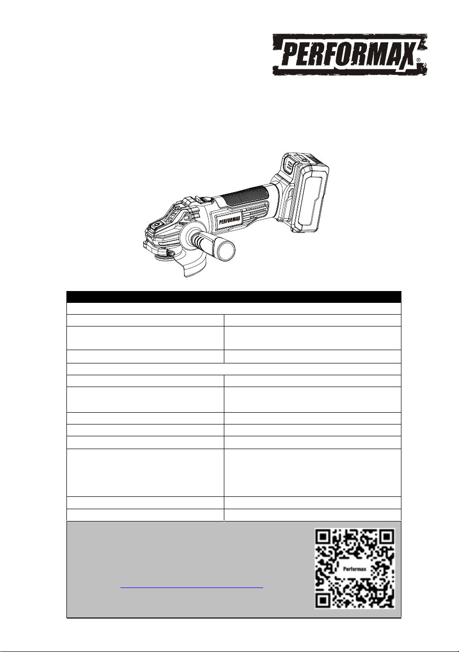
20 VOLT LITHIUM ION ANGLE GRINDER
241-9043
Owner’s Manual
PRODUCT SPECIFICATIONS
ANGLE GRINDER
Speed: 11000 RPM (no load)
Maximum disc/wheel diameter:
4½" (115 mm)
*Accessories sold separately
Arbor size:
5/8" – 11UNC with 7/8" flange
BATTERY & CHARGER
Battery: 20 V, Lithium ion
Charge time: Approx. 100 minutes for 2Ah battery
and 200 minutes for 4Ah battery
Charger input: 100–240V AC, 50–60 Hz
Charger output: 21.5 V DC, 1.5 A
Weight: 4.93 lbs with battery
Need Assistance?
• Technical questions
• Replacement parts
• Parts missing from package
Email us at:
Call us on our toll-free customer support line:1-866-349-8665
(9-5pm Monday-Friday EST)
Replacement battery:
Replacement charger:
Replacement battery & charger kit:
236-9049, 236-9050, 267-3207
* For optimal performance, use
4Ah Performax or Yardworks
replacement batteries.
236-9051, 267-3002, 267-3205
241-9040
Scan here for support

2
Product specifications ………….……………………………………………………. 1
Table of contents ……………………………………………………………………... 2
General safety warnings …………………………………………………………….. 3–4
Eye, ear & lung protection …………………………………………………………… 3–4
Electrical safety ………………………………………………………………………. 4
Power tool safety ……………………………………………………………………... 5–6
Work area ………………………………………………………………….………….. 5
Electrical safety ………………………………………………………………………. 5
Personal safety ……………………………………………………………………….. 5
Power tool use and care .……………………………………………………………. 6
Battery tool use and care ……………………………………………………………. 6
Service ………………………………………………………………………………… 6
Specific safety rules ………………………………………………………………….. 7-11
Battery & charger safety ………………………………………………………….…. 12
Battery pack recycling ……………………………………………………………….. 12
Symbols ……………………………………………………………………………….. 13
Know your angle grinder …………………………………………………… 14
Know guards and optional accessories …………………………………………… 15
Assembly and operating …………………………………………………………….. 17–23
Charging and installing the battery pack…………………………………………… 16–17
Installing the auxiliary handle ……………………………………………………… 17
Installing guards ……………………………………………………………………... 17-18
Positioning the wheel guard ………..……………………………………………… 18
Installing non-threaded wheels …………………………………………................. 18-19
Installing sanding backing pad ………………………………………….................. 19-20
ON/OFF switch …………………………………………………....................... 21
Using the angle grinder………………………………………………....................... 22-23
Installing and removing threaded wheels …………………………………………. 20
Installing wire cup brushes and wire wheels ……………………………………… 20-21
Maintenance …………………………………………………………………………... 24
Exploded view
………………………………………………………………………… 25
Parts list ……………………………………………………………………………….. 26
Warranty ……………………………………………………………………….……… 27
TABLE OF CONTENTS
3
EYE, EAR & LUNG PROTECTION
This instruction manual includes the following:
General Safety Warnings
Specific Safety Rules and Symbols
Functional Description
Assembly
Operation
Maintenance
!
ALWAYS WEAR EYE PROTECTION THAT CONFORMS WITH CSA
REQUIREMENTS or ANSI SAFETY STANDARD Z87.1
FLYING DEBRIS can cause permanent eye damage. Prescription
eyeglasses ARE NOT a replacement for proper eye protection.
WARNING: Non-compliant eyewear can cause serious injury if
broken during the operation of a power tool.
WARNING: Use hearing protection, particularly during extended
periods of operation of the tool, or if the operation is noisy.
!
GENERAL SAFETY WARNINGS
WARNING: Before using this tool or any of its accessories, read this
manual and follow all Safety Warnings and Operating Instructions. The important
precautions, safeguards and instructions appearing in this manual are not
meant to cover all possible situations. It must be understood that common
sense and caution are factors which cannot be built into the product.
!
SAVE THESE INSTRUCTIONS FOR REFERENCE
4
ELECTRICAL SAFETY
GENERAL SAFETY WARNINGS
WEAR A DUST MASK THAT IS DESIGNED TO BE USED WHEN
OPERATING A POWER TOOL IN A DUSTY ENVIRONMENT.
WARNING: Dust that is created by power sanding, sawing, grinding,
drilling, and other construction activities may contain chemicals that are
known to cause cancer, birth defects, or other genetic abnormalities. These
chemicals include:
Lead from lead-based paints
Crystalline silica from bricks, cement, and other masonry products
Arsenic and chromium from chemically treated lumber
The level of risk from exposure to these chemicals varies, according to how
often this type of work is performed. In order to reduce exposure to these
chemicals, work in a we
ll-ventilated area, and use approved safety
equipment, such as a dust mask that is specifically designed to filter out
microscopic particles.
!
WARNING: To avoid electrical hazards, fire hazards or damage to the
tool, use proper circuit protection.
This tool charger is wired at the factory for 120 V AC operation. It must be
connected to a 120 V AC, 15 A circuit that is protected by a time-delayed
fuse or circuit breaker. To avoid shock or fire, replace power cord
immediately if it is worn, cut or damaged in any way.
SAVE THESE INSTRUCTIONS FOR REFERENCE

5
WARNING: Read all safety warnings
and instructions. Failure to follow the warnings
and instructions may result in electric shock, fire
and/or serious injury.
Save all warnings and instructions for future
reference.
Work area safety
Keep work area clean and well lit. Cluttered or
dark areas invite accidents.
Do not operate power tools in explosive
atmospheres, such as in the presence of
flammable liquids, gases or dust. Power tools
create sparks which may ignite the dust or
fumes.
Keep children and bystanders away while
operating a power tool. Distractions can cause
you to lose control.
Electrical safety
Power tool plugs must match the outlet.
Never modify the plug in any way. Do not
use any adap
ter plugs with earthed
(grounded) power tools. Unmodified plugs and
matching outlets will reduce risk of electric
shock.
Avoid body contact with earthed or
grounded surfaces such as pipes, radiators,
ranges and refrigerators. There is an
increased risk of electric shock if your body is
earthed or grounded.
Do not expose power tools to rain or wet
conditions. Water entering a power tool will
increase the risk of electric shock.
Do not abuse the cord. Never use the cord
for carrying, pulling or unplugging the power
tool. Keep cord away from heat, oil, sharp
edges or moving parts. Damaged or
entangled cords increase the risk of electric
shock.
When operating a power tool outdoors, use
an extension cord suitable for
outdoor use.
Use of a cord suitable for outdoor use reduces
the risk of electric shock.
If operating a power tool in a damp location
is unavoidable, use a residual current device
(RCD) protected supply. Use of a ground fault
circuit interrupter (GFCI) reduces the risk of
electric shock.
Personal safety
Stay alert, watch what you are doing and use
common sense when operating a power tool.
Do not use a power tool while you are tired
or under the influence of drugs, alcohol or
medication. A moment of inattention while
operating power tools may result in serious
personal injury.
Use personal protective equipment. Always
wear eye protection. Protective equipment
such as dust mask, non-skid safety shoes, hard
hat, or he
aring protection used for appropriate
conditions will reduce personal injuries.
Prevent unintentional starting. Ensure the
switch is in the off-position before
connecting to power source and/or battery
pack, picking up or carrying the tool.
Carrying power tools with your finger on the
switch or energizing power tools that have the
switch on invites accidents.
Remove any adjusting key or wrench before
turning the power tool on. A wrench or a key
left attached to a rotating part of the power tool
may result in personal injury.
Do not overreach. Keep proper footing and
balance at all times. This enables better
control of the power tool in unexpected
situations.
Dress properly. Do not wear loose clothing
or jewelry. Keep
your hair, clothing and
gloves away from moving parts. Loose
clothes, jewelry or long hair can be caught in
moving parts.
Do not let familiarity gained from frequent
use of tools allow you to become complacent
and ignore tool safety principles. A careless
action can cause severe injury within a fraction
of a second.
Use only safety equipment that has been
approved by an appropriate standards agency.
Unapproved safety equipment may not provide
adequate protection. Eye protection must be
ANSI-approved and breathing protection must
be NIOSH-approved for the specific hazards in
the work area.
If devices are provided for the connection of
dust extraction and collection facilities,
ensure these are connected and properly
used. Use of dust collection can reduce dust-
related hazards.
POWER TOOL SAFETY
!

Do not use a battery pack or tool that is
damaged or modified. Damaged or modified
batteries may exhibit unpredictable behavior
resulting in fire, explosion or risk of injury.
Do not expose a battery pack or tool to fire or
excessive temperature. Exposure to fire or
temperature above 113°F (45°C) may cause
explosion.
Follow all charging instructions and do not
charge the battery pack or tool outside the
temperature range specified in the instruc-
tions. Charging improperly or at temperatures
outside the specified range may damage the
battery and increase the risk of fire.
6
Keep handles and grasping surfaces dry,
clean and free from oil and grease. Slippery
handles and grasping surfaces do not allow for
safe handling and control of the tool in unexpect-
ed situations.
Power tool use and care
Do not force the power tool. Use the correct
power tool for your application. The correct
power tool will do the job better and safer at the
rate for which it was designed.
Do not use the power tool if the switch does
not turn it on and off. Any power tool that
cannot be controlled with the switch is
dangerous and must be repaired.
Disconnect the plug from the power source
and/or the battery pack from the power tool
before making any adjustments, changing
accessories, or storing power tools. Such
preventive safety measures reduce the risk of
starting the power tool accidentally.
Store idle power tools out of the reach of
children and do not allow persons unfamiliar
with the
power tool or these instructions to
operate the power tool. Power tools are
dangerous in the hands of untrained users.
Maintain power tools. Check for
misalignment or binding of moving parts,
breakage of parts and any other condition
that may affect the power tool’s operation. If
damaged, have the power tool repaired
before use. Many accidents are caused by
poorly maintained power tools.
Keep cutting tools sharp and clean. Properly
maintained cutting tools with sharp cutting
edges are less likely to bind and are easier to
control.
Use the power tool, accessories and tool bits
etc. in accordance with these instructions,
taking into account the working conditions
and the work to be performed. Use of the
power tool for operations different from those
intended could result in a hazardous situat
ion.
Hold power tool by insulated gripping
surfaces, because the blade may contact its
own cord. Cutting a "live" wire may make
exposed metal parts of the tool "live" and could
give the operator an electric shock.
Battery tool use and care
Recharge only with the charger specified by
the manufacturer. A charger that is suitable for
one type of battery pack may create a risk of fire
when used with another battery pack.
Use power tools only with specifically
designated battery packs. Use of any other
battery packs may create a risk of injury and
fire.
When battery pack is not in use, keep it away
from other metal objects, like paper clips,
coins, keys, nails, screws or other small
metal objects that can make a connection
from one terminal to
another. Shorting the
battery terminals together may cause burns or a
fire.
Under abusive conditions, liquid may be
ejected from the battery; avoid contact. If
contact accidentally occurs, flush with water.
If liquid contacts eyes, additionally seek
medical help. Liquid ejected from the battery
may cause irritation or burns.
Service
Have your power tool serviced by a qualified
Never service damaged battery packs.
Service of battery packs should only be
performed by the manufacturer or authorized
service providers.
repair person using only identical
replacement parts. This will ensure that the
safety of the power tool is maintained.
POWER TOOL SAFETY

7
WARNING: Know your cordless
angle grinder. Do not plug in the charger or
install the battery in the tool until you have
read and understand this Instruction Manual.
Learn the tool’s applications and limitations,
as well as the specific potential hazards
related to this tool. Following this rule will
reduce the risk of electric shock, fire, or serious
injury.
Always wear eye protection. Any
power tool can throw foreign
objects into your eyes and cause
permanent eye damage.
ALWAYS wear safety goggles (not glasses) that
comply with ANSI safety standard Z87.1.
Everyday glasses have only impact resistant
lenses. They ARE NOT safety glasses.
SPECIFIC SAFETY RULES
SAVE THESE INSTRUCTIONS FOR REFERENCE
SAVE THESE INSTRUCTIONS FOR REFERENCE
!
WARNING: Glasses or goggles not in
compliance with ANSI Z87.1 could cause
serious injury when they break.
!
This power tool is intended to function as a
grinder, sander, wire brush or cut-off tool.
Read all safety warnings, instructions,
illustrations and specifications provided with
this power tool. Failure to follow all instructions
listed below may result in electric shock, fire
and/or serious injury and/or damage to the work
piece.
Operations such as polishing are not
recommended to be performed with this
power tool. Operations for which the power tool
was not designed may create a hazard and
cause personal injury and/or damage to the work
piece.
Do not use accessories which are not
specifically designed and recommended by
the tool manufacturer. Just because the
accessory can be attached to your power tool, it
does not assure safe operation.
The rated speed of the accessory must be at
least equal to the maximum speed marked on
the power tool. Accessories running faster than
their rated speed can break and fly apart.
The outside diameter and the thickness of
your accessory must be within the capacity
rating of your power tool. Incorrectly sized
accessories cannot be adequately guarded or
controlled.
Threaded mounting of accessories must
match the grinder spindle thread. For
accessories mounted by flanges, the arbor
hole of the accessory must fit the locating
diameter of the flange. Accessories that do not
match the mounting hardware of the power tool
will run out of balance, vibrate excessively and
may cause loss of control.
Do not use a damaged accessory. Before
each use inspect the accessory such as
abrasive wheels for chips and cracks,
backing pad for cracks, tear or excess wear,
wire brush for loose or cracked wires. If
power tool or accessory is dropped, inspect
for damage or install an undamaged accessory.
After inspecting and installing an accessory,
position yourself and bystanders away from
the plane of the rotating accessory and run
the power tool at maximum no-load speed for
one minute. Damaged accessories will normally
break apart during this test time.
Wear personal protective equipment.
Depending on application, use face shield,
safety goggles or safety glasses. As appro-
priate, wear dust mask, hearing protectors,
gloves and workshop apron capable of
stopping small abrasive or workpiece
fragments. The eye protection must be
capable of stopping flying debris generated
by various operations. The dust mask or
respirator must be capable of filtrating
particles generated by your operation.
Prolonged exposure to high intensity noise may
cause hearing loss.
SAFETY INSTRUCTIONS FOR ALL
OPERATIONS
Safety Warnings Common for Grinding,
Sanding, Wire Brushing or Abrasive
Cutting-Off Operations

8
SPECIFIC SAFETY RULES
SAVE THESE INSTRUCTIONS FOR REFERENCE
SAVE THESE INSTRUCTIONS FOR REFERENCE
Keep bystanders a safe distance away from
work area. Anyone entering the work area
must wear personal protective equipment.
Fragments of workpiece or of a broken accessory
may fly away and cause injury beyond immediate
area of operation.
Hold the power tool by insulated gripping
surfaces only, when performing an operation
where the cutting tool may contact hidden
wiring. Contact with a “live” wire will also make
exposed metal parts of the power tool “live” and
could give the operator an electric shock.
Never lay the power tool down until the
accessory has come to a complete stop. The
spinning accessory may grab the surface and
pull the power tool out of your control.
Do not run the power tool while carrying it at
your side. Accidental contact with the spinning
accessory could snag your clothing, pulling the
accessory into your body.
Regularly clean the power tool’s air vents.
The motor’s fan will draw the dust inside the
housing and excessive accumulation of
powdered metal may cause electrical hazards.
Do not operate the power tool near flammable
materials. Sparks could ignite these materials.
Do not use accessories that require liquid
coolants. Using water or other liquid coolants
may result in electrocution or shock.
Do not use Type 11 (flaring cup) wheels on
this tool. Using inappropriate accessories can
result in injury.
Always use side handle. Tighten the handle
securely. The side handle should always be
used to maintain control of the tool at all times.
When starting the tool with a new or
replacement wheel, or a new or replacement
wire brush installed, hold the tool in a well
protected area and let it run for one minute. If
the wheel has an undetected crack or flaw, it
should burst in less than one minute. If the
wire brush has loose wires, they will be
detected. Never start the tool with a person in
line with the wheel. This includes the operator.
Use of accessories not specified in this
manual is not recommended and may be
hazardous. Use of power boosters that would
cause the tool to be driven at speeds greater
than its rated speed constitutes misuse.
Use clamps or another practical way to
secure and support the workpiece to a stable
platform. Holding the work by hand or against
your body leaves it unstable and may lead to loss
of control.
Avoid bouncing the wheel or giving it rough
treatment. If this occurs, stop the tool and
inspect the wheel for cracks or flaws.
Always handle and store wheels in a careful
manner.
Do not operate this tool for long periods of
time. Vibration caused by the operating
action of this tool may cause permanent
injury to fingers, hands, and arms. Use gloves
to provide extra cushion, take frequent rest
periods, and limit daily time of use.
Air vents often cover moving parts and
should be avoided. Loose clothes, jewelry or
long hair can be caught in moving parts.
KICKBACK AND RELATED WARNINGS
Kickback is a sudden reaction to a pinched or
snagged rotating wheel, backing pad, brush or
any other accessory. Pinching or snagging
causes rapid stalling of the rotating accessory
which in turn causes the uncontrolled power tool
to be forced in the direction opposite of the
accessory’s rotation at the point of the binding.
For example, if an abrasive wheel is snagged or
pinched by the workpiece, the edge of the wheel
that is entering into the pinch point can dig into
the surface of the material causing the wheel to
climb out or kick out. The wheel may either jump

WARNING: Use of Accessories Rated
for Grinder Speed.
!
9
SPECIFIC SAFETY RULES
SAVE THESE INSTRUCTIONS FOR REFERENCE
SAVE THESE INSTRUCTIONS FOR REFERENCE
toward or away from the operator, depending on
direction of the wheel’s movement at the point of
pinching. Abrasive wheels may also break under
these conditions. Kickback is the result of tool
misuse and/or incorrect operating procedures or
conditions and can be avoided by taking proper
precautions as given below:
Maintain a firm grip on the power tool and
position your body and arm to allow you to
resist kickback forces. Always use auxiliary
handle, if provided, for maximum control over
kickback or torque reaction during start up.
The operator can control torque reaction or
kickback forces, if proper precautions are taken.
Never place your hand near the rotating
accessory. Accessory may kickback over your
hand.
Do not position your body in the area where
power tool will move if kickback occurs.
Kickback will propel the tool in direction opposite
to the wheel’s movement at the point of snagging.
Use special care when working corners, sharp
edges etc. Avoid bouncing and snagging the
accessory. Corners, sharp edges or bouncing
have a tendency to snag the rotating accessory
and cause loss of control or kickback.
Do not attach a saw chain woodcarving blade
or toothed saw blade. Such blades create
frequent kickback and loss of control.
Safety Warnings Specific for Grinding and
Abrasive Cutting-Off Operations
Before using this angle grinder, ensure that all
accessories (such as cutting discs, sanding pads,
or grinding wheels) are rated for operation at the
maximum speed of 11,000 RPM. Using accesso-
ries that are not designed for such high-speed
operation may lead to accessory failure,
excessive wear, or dangerous breakage, posing
a significant risk of injury to the operator and
bystanders.
Important:
Always check the speed rating printed on the
accessory before use.
Never exceed the manufacturer’s recommended
speed for any accessory.
Only use accessories designed specifically for
high-speed grinders.
Always use the proper guard that is compatible
with the accessory in use to ensure maximum
protection during operation.
Follow the accessory manufacturer's safety
instructions, operating guidelines, and warnings
to ensure safe use.
Ensure that the accessory is properly secured
and fitted to the tool before operation.
Failure to follow these safety precautions may
result in serious injury or damage to the tool.
Never use a cut-off wheel for grinding or a
grinding disc for cutting.
Use only wheel types that are recommended
for your power tool and the specific guard
designed for the selected wheel. Wheels for
which the power tool was not designed cannot
be adequately guarded and are unsafe.
The grinding surface of center depressed
wheels must be mounted below the plane of
the guard lip. An improperly mounted wheel
that
projects through the plane of the guard lip
cannot be adequately protected.
The guard must be securely attached to the
power tool and positioned for maximum
safety, so the least amount of wheel is
exposed towards the operator. The guard
helps to protect the operator from broken wheel
fragments, accidental contact with wheel and
sparks that could ignite clothing.

Wheels must be used only for recommended
applications. For example: do not grind with
the side of cut-off wheel. Abrasive cut-off
wheels are intended for peripheral grinding,
side forces applied to these wheels may cause
them to shatter.
Always use undamaged wheel flanges that
are of correct size and shape for your
selected wheel. Proper wheel flanges
support the wheel thus reducing the
possibility of wheel breakage. Flanges for
cut-off wheels may be different from grinding
wheel flanges.
Do not use worn down wheels from larger
power tools. Wheel intended for larger power
tool is not suitable for the higher speed of a
smaller tool and may burst.
Dress appropriately. Wear leather leggings
and fire resistant footwear during use. Do
not wear pants with cuffs, shirts with pockets, or
any clothing that can catch and hold molten
metal or sparks.
Additional Safety Warnings Specific for
Abrasive Cutting-Off Operations
Do not “jam” the cut-off wheel or apply
excessive pressure. Do not attempt to make
an excessive depth of cut. Overstressing the
wheel increases the loading and susceptibility
to twisting or binding of the wheel in the cut and
the possibility of kickback or wheel breakage.
Do not position your body in line with and
behind the rotating wheel. When the wheel, at
the point of operation, is moving away from
your body, the possible kickback may propel
the spinning wheel and the power tool directly
at you.
When wheel is binding or when interrupting
a cut for any reason, switch off the power
tool and hold the power tool motionless
until the wheel comes to a complete stop.
10
SPECIFIC SAFETY RULES
SAVE THESE INSTRUCTIONS FOR REFERENCE
SAVE THESE INSTRUCTIONS FOR REFERENCE
Never attempt to remove the cut-off wheel
from the cut while the wheel is in motion
otherwise kickback may occur. Investigate and
take corrective action to eliminate the cause of
wheel binding.
Do not restart the cutting operation in the
workpiece. Let the wheel reach full speed and
carefully reenter the cut. The wheel may bind,
walk up or kickback if the power tool is restarted
in the workpiece.
Support panels or any oversized workpiece
to minimize the risk of wheel pinching and
kickback. Large workpieces tend to sag under
their own weight. Supports must be placed
under the workpiece near the line of cut and near
the edge of the workpiece on both sides of the
wheel.
Use extra caution when making a “pocket
cut” into existing walls or other blind areas.
The protruding wheel may cut gas or water pipes,
electrical wiring or objects that can cause
kickback.
Safety Warnings Specific for Sanding
Operations
Do not use excessively oversized sanding
disc paper. Follow manufacturers recommen-
dations, when selecting sanding paper. Larger
sanding paper extending beyond the sanding pad
presents a laceration hazard and may cause
snagging, tearing of the disc or kickback.
Safety Warnings Specific for Wire
Brushing Operations
Be aware that wire bristles are thrown by the
brush even during ordinary operation. Do not
overstress the wires by applying excessive
load to the brush. The wire bristles can easily
penetrate light clothing and/or skin.

If the use of a guard is recommended for
wire brushing, do not allow any interference
of the wire wheel or brush with the guard.
Wire wheel or brush may expand in diameter
due to work and centrifugal forces.
Safety goggles or safety glasses with side
shields and a full face shield compliant with
ANSI Z87.1 MUST be worn by the operator
and others that are within 50' (15.2 m) of the
use of this product.
ADDITIONAL SAFETY WARNING
Use suitable detectors to determine if utility
lines are hidden in the work area or call the
local utility company for assistance. Contact
with electric lines can lead to fire and electric
shock. Damaging a gas line can lead to
explosion. Penetrating a water line causes
property damage or may cause an electric
shock.
Do not touch grinding and cutting discs until
they have cooled down. The discs can become
very hot while working.
Secure the workpiece. A workpiece clamped
with clamping devices or in a vice is held more
secure than by hand.
Loose clothing or hair can become entangled in
the rotating disc, leading to serious injury.
Flying debris, sparks, and potential contact with
the rotating disc can cause eye and skin
injuries. Appropriate personal protective
equipment (PPE), such as eye protection,
gloves, and respiratory protection, is crucial.
Angle grinders can generate a lot of dust,
especially during sanding operations. This dust
can be harmful to the respiratory system,
potentially leading to silicosis or other
respiratory illnesses.
11
SPECIFIC SAFETY RULES
SAVE THESE INSTRUCTIONS FOR REFERENCE
SAVE THESE INSTRUCTIONS FOR REFERENCE
VIBRATON SAFETY
This tool vibrates during use. Repeated or
long-term exposure to vibration may cause
temporary or permanent physical injury,
particularly to the hands, arms and shoulders. To
reduce the risk of vibration-related injury:
1. Do not smoke during use. Nicotine reduces the
blood supply to the hands and fingers, increasing
the risk of vibration-related injury.
2. Wear suitable gloves to reduce the vibration
effects on the user.
3. Use tools with the lowest vibration when there
is a choice between different processes.
4. Include vibration-free periods. Grip tool as
lightly as possible (while still keeping safe control
of it). Let the tool do the work.
5. To reduce vibration, maintain the tool as
explained in this manual. If any abnormal
vibration occurs, stop use immediately.

12
WARNING: Only use the charger
supplied with this kit to charge Perfor-
max® and Yardworks® 20V battery
236-9049, 236-9050, 267-3206, 267-3207,
other types of batteries may burst causing
personal injury and damage.
Do not store or carry the battery in a manner in
which metal objects could contact the exposed
metal end. Do not place the battery in aprons,
pockets, drawers, etc. with loose nails, screws,
keys etc. The battery could short circuit causing
a fire, personal injury or damage to the battery.
Never attempt to open the battery for any
reason. If the housing of the battery breaks or
cracks, immediately discontinue use and do not
recharge.
Do not charge the battery if it is wet or shows
any evidence of corrosion.
A small leakage from the battery may occur
under extreme usage, charging or temperature
conditions. This does not indicate a failure.
However, if the outer seal is broken and this
leakage gets on your ski
n, follow these steps:
1. Wash immediately with soap and water.
2. Neutralize with a mild acid such as lemon
juice or vinegar.
3. If liquid gets into your eyes, flush
immediately with clean water for a
minimum of 10 minutes and seek medical
attention.
NOTE: The battery liquid is slightly acidic.
Do not incinerate the battery. It can explode in a
fire.
Do not use an extension cord. Plug the charger
cord directly into an electrical outlet.
Use the charger only in a standard
120V, 60 Hz electrical outlet.
Do not use the charger in wet or damp
conditions. It is intended for indoor use only.
Do not use the charger near sink
Do not immerse the charger in water. Do not
allow the cord to hang over the edge of a
BATTERY & CHARGER SAFETY
SAVE THESE INSTRUCTIONS FOR REFERENCE
!
table or counter or touch hot surfaces. The
charger should be placed away from sinks and
hot surfaces.
Do not operate charger if the cord or plug is
damaged. Replace the damaged cord and plug
immediately.
Do not operate the charger if it has received a
sharp blow, been dropped or otherwise
damaged in any way. Have a qualified
technician examine the charger and repair it if
necessary. Do not disassemble the charger.
Do NOT charge the batteries when the work
area or the battery temperature is at or below
32°F (0°C) or above 113°F (45°C).
Unplug the charger when not in use and before
cleaning or maintenance.
BATTERY PACK RECYCLING
To preserve our natural resources, please
recycle or dispose of batteries properly.
The batteries charged by this charger may
contain chemicals and metals that are harmful
to the environment. Never dispose of rechargeable
batteries in your normal household garbage or
in lan
dfill sites as they will add to the pollution of
the environment.
Please call 1-800-822-8837 for the location of
your nearest RBRC battery recycling location.
13
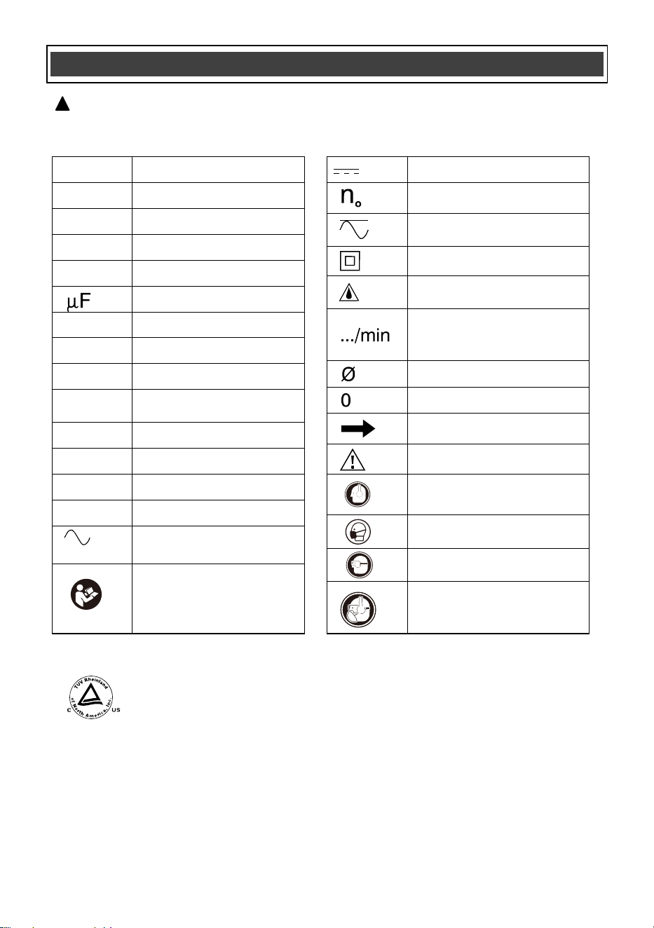
SYMBOLS
WARNING: Some of the following symbols may appear on the angle grinder.
Study these symbols and learn their meaning. Proper interpretation of these symbols
will allow for more efficient and safer operation of this tool.
!
This symbol designates that this tool is listed with U.S.
requirements by TÜV Rheinland (Shanghai) Co., Ltd.
Conforms to UL62841-1,UL62841-2-3
Certified to CAN/CSA Std. C22.2 No. 62841-1 and 62841-2-3.
JD5981
Wear hearing protection.
Wear eye protection.
Wear breathing protection.
Read instruction manual.
To reduce the risk of
injury, user must read
instruction manual.
V
Volts
A
Amperes
Hz
Hertz
W
Watts
kW
Kilowatts
Microfarads
kg
Kilograms
H
Hours
N/cm
2
Newtons per square
centimeter
Pa
Pascals
OPM
Oscillations per minute
Min
Minutes
S
Seconds
or a.c.
Alternating current
Direct current
No load speed
Alternating or direct
current
Class II construction
Splash-proof
construction
Revolutions or
reciprocations per
minute
Diameter
Off position
Directional Arrow
Warning symbol
Wear hearing protection.
Wear breathing protection.
Wear eye protection.
or DC
lbs
Pounds, Weight
14
KNOW YOUR ANGLE GRINDER
Battery charger adapter
Wheel guard clamp lever
Grinding guard
Grinding disc/wheel (not included)
Outer disc flange
Inner disc flange
Charging status indicator light
Battery charger cap
Battery
Wrench
ON/OFF sliding switch
Spindle lock
button
3-Position auxiliary handle
Cutting guard
WARNING: Cutting wheels can only be used together with cutting guard. The
rated speed of optional accessories must not be less than 11,000 RPM.
!
15
KNOW GUARDS AND OPTIONAL ACCESSORIES
1
2
3
4
1
5
1
11
1
2
6
4
1
7
13
2
14
4
13
2
15
4
8
9
10
1
12
13
2
16
4
No.
1
2
3
4
5
6
7
8
9
10
11
12
13
14
15
16
Description
Grinding guard
Inner flange
1/4" type 27 non-threaded depressed center grinding wheel, 7/8" bore size
Outer flange
1/4" type 27 threaded depressed center grinding wheel, 7/8" bore size
1/4" Non-threaded sanding flap disc, 7/8" bore size
1/4" Threaded sanding flap disc, 5/8"-11 bore size
Sanding backing pad
Sanding disc
Locking nut,5/8"-11 bore size
3-4" threaded wire cup brush, 5/8" bore size
4" threaded wire wheel, 5/8" bore size
Cutting guard
1/4" type 27/42 non-threaded depressed center cutting wheel, 7/8" bore size
1/4" type 1/41 non-threaded abrasive cutting wheel, 7/8" bore size
1/4" non-threaded diamond cutting wheel, 7/8" bore size
*Accessories sold separately
16
ASSEMBLY AND OPERATING
CHARGING THE BATTERY PACK
WARNING: Do not use the charger
outdoors or expose it to wet or damp
conditions. Water entering the charger will
increase the risk of electric shock.
NOTICE: Lithium-Ion battery packs are
shipped partially charged. Before using it
the first time, you must fully charge it.
NOTICE: You can only charge one battery at
a time with the charger provided.
1. Plug the battery charger adapter into the
battery charger cap and then plug the adapter
(2) into a power supply (120V~60Hz). The
charging status indicator LED light (3) will turn
green indicating that the charger is working
correctly.
!
2. Align the raised ribs of the battery (1) with the
battery-mounting slots in the battery charge
cap (4); slide the cap onto the battery. If
installed correctly the charging status indicator
light on the charger will turn red indicating the
battery is charging (see chart on this page) and
the battery charge level indicator lights on the
battery will flash.
3. When the battery is fully charged the light on
the charger will turn green and the lights on the
battery will turn off or keeps on. Once the
charge cap is removed from the battery (never
check while charging cap is installed on the
battery) you may confirm the charge status of
the battery. When fully charged all battery
charge level indicator lights should be lit.
BATTERY CHARGE LEVEL INDICATOR LIGHTS
To check the battery charge level, press the
push button on the battery pack. The LED
indicator lights will show the current charge
levels as indicated in chart below.
NOTE:
If one indicator light begins to flash, the battery
charge level is under 10% capacity and should
be recharged soon.
If three indicator lights begin to flash at a rate of
1 or 2 times per second, the battery is too hot,
and cool the battery till its temperature drops
below 152°F (67°C).
If three indicator lights begin to flash at a rate of
5 times per second, the battery is defective,
please recycle or dispose of batteries properly,
or contact Customer Service.
Indicator
Lights
3 lights on
2 lights on
1 light on
1 light flashing
Battery Charge Level
70%<Charge Level≤100%
40%<Charge Level≤70%
10%<Charge Level≤40%
Charge Level ≤10%
NOTE:
The battery cannot be correctly charged on
the charger if the battery pack is too hot or
too cold and not within normal temperature
range 41°F (5°C) - 113°F (45°C). Allow the
battery pack to reach normal temperature,
and charging will begin.
The battery pack will fully charge if left on
the charger, but it will not overcharge.
A significantly reduced runtime after fully
charging the battery pack indicates that the
batteries are nearing the end of their usable
life and must be replaced.
The charger may become warm during
charging. This is a normal part of its
operation. Always charge in a well-ventilated
area.
Fig. 1
17
ASSEMBLY AND OPERATING
1
CHARGING THE BATTERY CONT’D
If the battery pack is completely discharged
and no LEDs flash when it is connected to
the charger, this indicates a malfunctioning
battery. In this case, do not attempt to
charge the battery.
INSTALLING THE BATTERY PACK IN THE
TOOL
1. Remove the discharged battery pack (1)
from the tool by pressing the battery
release button (2) on the front of the
battery pack and pulling the battery pack
out of the tool handle (3) (Fig. 2).
2. Insert the fully charged battery pack into
the matching slots in the tool handle where
the discharged battery pack has been
removed.
NOTE: The battery release button will
“click” into place when the battery pack is
fully installed.
WARNING: Do not immerse battery
pack in water. Sudden cooling could cause a
hot battery to explode or leak.
!
Charging
status
indicator light
Green NO
Charger
connected
to power
supply
Red YES
Battery is
being charged
Green YES
Battery fully
charged
Charger cap
installed on
battery
Charging
Status
Fig. 2
2
3
INSTALLING THE AUXILIARY HANDLE
1. Remove the battery from the tool.
2. Install the auxiliary handle (1) by screwing
it clockwise into the gear housing (2). The
handle can be attached in one of three
positions: the left side, right side, or top
center of the tool, depending on your
preference (see Fig. 3).
3. Tighten the auxiliary handle securely by
hand. Ensure it is firmly in place, but do not
over-tighten.
INSTALLING GUARDS
WARNING: The auxiliary handle must
always be used to prevent loss of control
and possible injury.
!
WARNING: To reduce the risk of serious
personal injury, turn tool off and disconnect
battery pack before making any adjustments
or removing/installing attachments or
accessories. An accidental start-up can
cause injury.
!
WARNING: Guards must be used with all
grinding wheels, cutting wheels, sanding
flap discs, wire brushes, and wire wheels.
Follow cautions and warnings from the accessory
manufacturer.
Guards must be installed before installing
accessories or using the angle grinder. Failure
to do so could result in serious personal injury.
!
Fig. 3
1
2
WARNING: Remove the battery from the
tool.
!
NOTE: Edge grinding and cutting can be
performed using Type 27 wheels that are
designed and specified for these tasks. Wheels
that are 6.35 mm (1/4") thick are intended for
surface grinding, while thinner Type 27 wheels
should be inspected for the manufacturer's label
to determine whether they are suitable for
surface grinding or are only intended for edge
grinding and cutting.
A cutting guard must be used for any wheel
where surface grinding is prohibited.
Additionally, cutting can also be performed
using a Type 41 wheel, provided that a cutting
guard is used.
1. Pull the wheel guard clamp lever (1)
outward to allow the wheel guard to
expand for installation.
2. Slide the wheel guard (2) over the spindle
housing (3) until the wheel guard locating
detents (4) mate with the grooves (5) in the
spindle housing (Fig. 4).
3. Press the wheel guard fully onto the
spindle housing.
WARNING: It's crucial to use angle
grinders with proper safety precautions,
including wearing appropriate personal
protective equipment (PPE) and using the
correct attachments for the task at hand.
!
WARNING: Failure to properly seat the
flanges and/or wheel could result in serious
injury (or damage to the tool or wheel).
18
ASSEMBLY AND OPERATING
NOTE:
Rotate the wheel guard so it is
positioned correctly depending upon the
location of the auxiliary handle in Fig. 5.
4. Push the wheel guard clamp lever toward
the wheel guard until the wheel guard
clamp lever firmly locks the wheel guard
onto the spindle housing.
Fig. 4
1
4
2
5
3
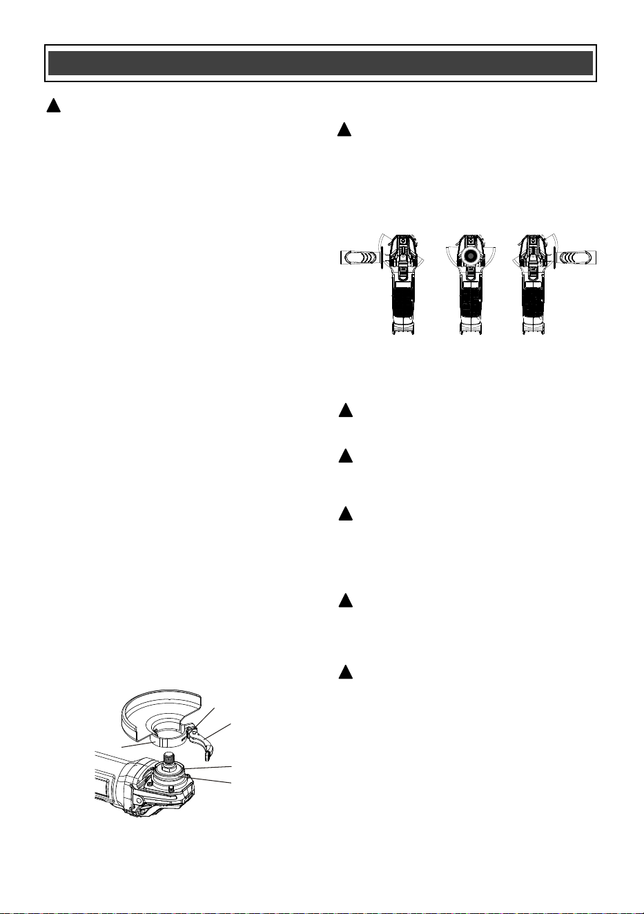
POSITIONING THE WHEEL GUARD
WARNING: The wheel guard must be
positioned correctly to protect the operator.
Wheel guard placement depends upon which
side of the tool the auxiliary handle is used,
to afford the greatest protection for the user.
Rotate the wheel guard to the correct
position as noted in Fig. 5 below.
!
Fig. 5
INSTALLING NON-THREADED WHEELS
!
CAUTION: Included flanges must be used
with depressed center Type 27/42 grinding
wheels and Type 1/41 cutting wheels. See the
KNOW GUARDS AND OPTIONAL ACCESSO-
RIES for more information.
!
WARNING: A closed, two-sided cutting
wheel guard is required when using abrasive
cutting wheels or diamond coated cutting
wheels.
!
WARNING: Use of a damaged flange or
guard or failure to use proper flange and
guard can result in injury due to wheel
breakage and wheel contact. See the KNOW
GUARDS AND OPTIONAL ACCESSORIES for
more information.
!
19
ASSEMBLY AND OPERATING
1. Lock the wheel guard onto the spindle
housing.
2. Depress the spindle lock button (1) and
rotate the outer disc flange (3) until the
spindle locks (Fig. 6).
3. Turn the outer disc flange counter
clockwise and remove it from spindle.
NOTES:
a) If the outer disc flange cannot be loosened by
hand, use the wrench (8) provided.
b) DO NOT remove the inner disc flange (5).
4. Make sure the flats on the bottom of inner
disc flange are engaged with the flats on
the spindle (6).
5. Place the disc/wheel (7) over the spindle
centering the wheel on the raised center of
the inner flange.
NOTE: for type 27 depressed center wheel/disc,
the concave side faces outward.
6. Screw the outer disc flange onto the
spindle. Tighten to finger tight only.
NOTE: The direction for mounting the outer
flange varies by wheel thickness. Refer to the
following figures
1. Outer flange
2. Cutting wheel/disc (Thinner than 5/32" (4mm))
3. Cutting wheel/disc (5/32" (4 mm) or thicker)
4. Inner flange
7. Depress the spindle lock button and rotate
the disc/wheel clockwise until the spindle
locks.
8. Securely tighten the outer disc flange with
the wrench provided.
NOTE: Use of a guard with sanding discs that
use backing pads, often called fiber resin discs,
is not required. Since a guard is not required for
these accessories, the guard may or may not fit
correctly if used.
WARNING: Remove the battery from the
tool.
!
Fig. 6
7
2
5
4
6
1
3
8
INSTALLING SANDING BACKING PAD
WARNING: Failure to properly seat the
clamp nut and/or pad could result in serious
injury (or damage to the tool or wheel).
!
WARNING: Proper guard must be
reinstalled for grinding wheel, cutting wheel,
sanding flap disc, wire brush or wire wheel
applications after sanding applications are
complete.
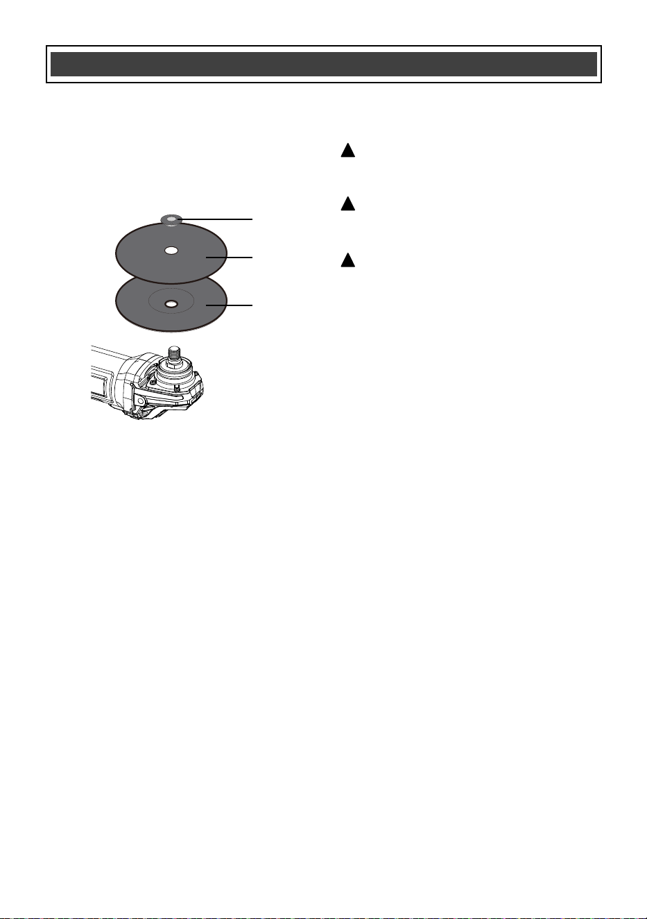
1.Place an appropriately thread backing pad (1)
on the spindle.
2.Place the sanding disc (2) on the backing pad
(1).
3.While depressing spindle lock button, thread
the sanding locking nut (3) on spindle, piloting
the raised hub on the clamp nut into the center
of sanding disc and backing pad.
!
WARNING:
For a Grinding Disc/Cut-Off Wheel
• Never use a disc/wheel with a rated speed of
less than 11,000 RPM
• Wheel must be no larger than 4-1/2" diameter.
• Proven undamaged by inspection.
!
1
1
2
3
7/8" (22 mm)
4
7/8" (22 mm)
4
20
ASSEMBLY AND OPERATING
Fig. 7
Threaded wheels install directly on the spindle.
Thread of accessory must match thread of
spindle.
1.Remove inner flange by pulling away from
tool.
2.Thread the wheel on the spindle by hand.
3.Depress the spindle lock button and use a
wrench to tighten the hub of the wheel.
4.Reverse the above procedure to remove the
wheel.
NOTICE: Failure to properly seat the wheel
before turning the tool on may result in damage
to the tool or the wheel.
INSTALLING AND REMOVING
THREADED WHEELS
Wire cup brushes or wire wheels install directly
on the threaded spindle without the use of
flanges. Use only wire brushes or wheels
provided with a threaded hub. These accesso-
ries are available at extra cost from your local
dealer or authorised service center.
1.Place the tool on a table, guard up.
2.Thread the wheel on the spindle by hand.
3.Depress spindle lock button and use a wrench
on the hub of the wire wheel or brush to tighten
the wheel.
4.To remove the wheel, reverse the above
procedure.
NOTICE: To reduce the risk of damage to the
tool, properly seat the wheel hub before turning
the tool on.
INSTALLING WIRE CUP BRUSHES AND
WIRE WHEELS
WARNING: Failure to properly seat the
brush/wheel could result in serious injury (or
damage to the tool or wheel).
!
CAUTION: To reduce the risk of personal
injury, wear work gloves when handling wire
brushes and wheels. They can become sharp.
!
CAUTION: To reduce the risk of damage
to the tool, wheel or brush must not touch
guard when mounted or while in use.
Undetectable damage could occur to the
accessory, causing wires to fragment from
accessory wheel or cup.
!
4.Tighten the locking nut by hand. Then depress
the spindle lock button while turning the sanding
disc until the sanding disc and locking nut are
snug.
5.To remove the wheel, grasp and turn the
backing pad and sanding pad while depressing
the spindle lock button (Fig. 7)
1
2
3
21
ASSEMBLY AND OPERATING
WARNING: Never attach a wood cutting
or carving blade of any type to this angle
grinder. This power tool is intended to
function as a grinder, sander, wire brush or
cutting tool only. Use for any other purpose
is not recommended and creates a hazard
which will result in serious injury.
!
WARNING: Never cover the air vents.
They must always be open for proper motor
cooling.
!
WARNING: When turning the angle
grinder OFF, always wait until the accessory
comes to a complete stop before setting the
tool down.
!
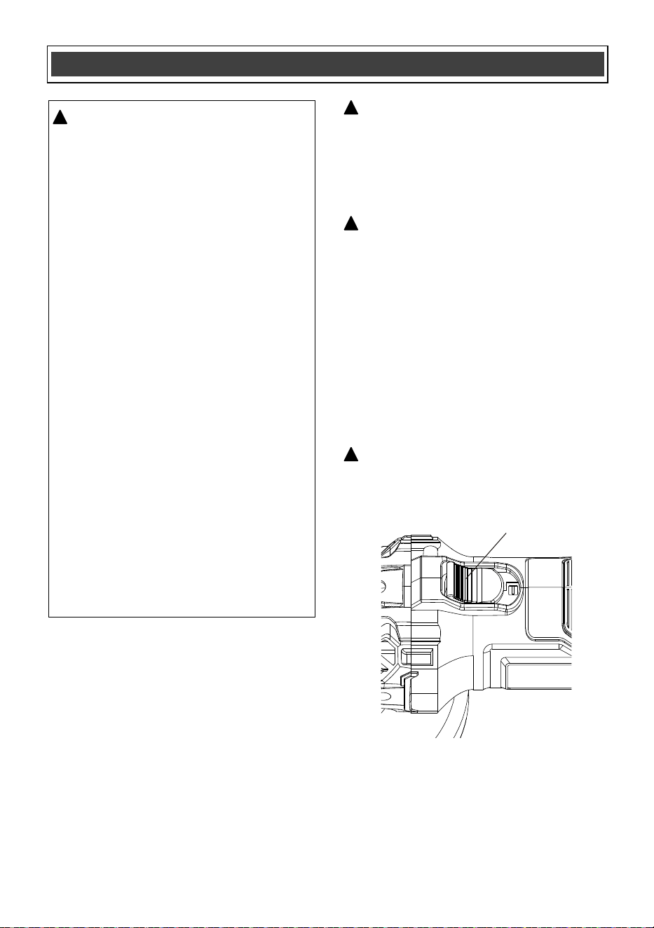
ON/OFF SLIDING SWITCH AND "LOCK-ON"
To turn the grinder ON, press the back of the
switch slider (1) into the body of the tool. While
pressing on the rear of the slider, push it
forward until the front part of the switch engages
the catch (Fig. 8). When the switch “snaps” into
position, the switch will 'lock-on" and the motor
will continue running. To turn the tool OFF,
press the rear of the slider into the angle grinder
body. The switch will “snap” to the OFF position.
Fig. 8
1
WARNING: For safety reasons, the
operator must read the sections of
this Owner’s Manual entitled "GENERAL
SAFETY WARNINGS", "POWER TOOL
SAFETY","SPECIFIC SAFETY RULES",
"EXTENSION CORD SAFETY"
(if applicable) and "SYMBOLS" before
using this angle grinder.
Verify the following every time the grinder
is used:
1. The grinding wheel/disc is securely
mounted and in good condition (not
cracked or worn).
2. All guards and safety covers are
properly installed and tightened.
3. The workpiece is securely clamped
or held in place.
4. Appropriate personal protective
equipment (PPE) is being worn —
including safety glasses or a face
shield, hearing protection, and
gloves.
Failure to follow these safety checks can
significantly increase the risk of injury.
Always inspect your tool and setup before
use.
!
22
ASSEMBLY AND OPERATING
WARNING: Always use the correct guard
per the instructions in this manual.
!
WARNING: Use extra care when working
over an edge, as a sudden sharp movement
of grinder may be experienced.
!
WARNING: Never use your angle grinder
without eye protection. Following this rule
will reduce the risk of serious personal
injury.
!
Always select and use accessories that are
appropriate for the job. Make sure that the
maximum operating speed of the grinding
accessory selected is not less than 11,000 RPM.
Secure all work before using the grinder.
Secure small workpieces in a vice or clamp to a
workbench.
To perform work on the surface of a workpiece:
1. For maximum control, hold the angle grinder in
front and away from you with both hands,
keeping the disc/wheel clear of the workpiece.
Start your angle grinder and let the motor and
disc/wheel build up to full speed.
2. Gradually lower the angle grinder until the
disc/wheel contacts the workpiece. Apply
minimum pressure to the work surface,
allowing the tool to operate at high speed.
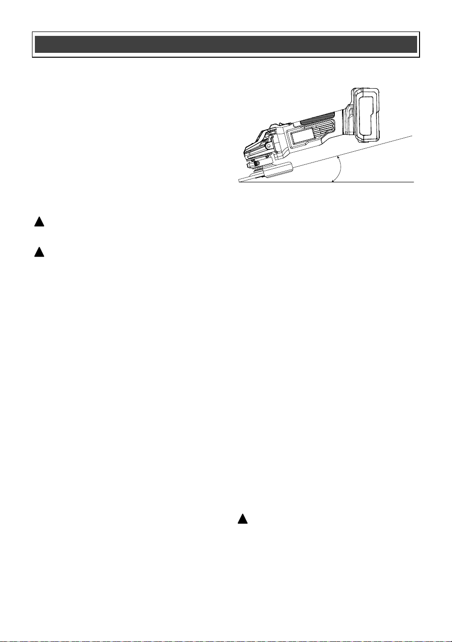
3. For best results keep the tool tilted at an angle
of between 5° and 15° degrees and
continuously moving at a steady, consistent
pace (Fig.9). Move the tool back and forth or
up and down over the work area. Keep the
tool moving so that an excessive amount of
material is not removed from one area. If the
tool is held in one spot too long, it will gouge
and cut grooves in the workpiece. If the tool is
held at too sharp an angle, it will gouge the
workpiece because of the concentration of
pressure on a small area.
4. Maintain contact between the edge of the
wheel and the work surface.
- If grinding, sanding with flap discs or wire
brushing move the tool continuously in a
forward and back motion to avoid creating
gouges in the work surface.
- If sanding with a backing pad, move the tool
constantly in a straight line to prevent burning
and swirling of work surface.
NOTE: Use just enough pressure to keep the
angle grinder from chattering or bouncing. Heavy
pressure will decrease its speed and put a strain
on the motor. Normally, the weight of the tool
alone is adequate for most grinding jobs. Use
light pressure when grinding jagged edges or
loose bolts where there is potential for the angle
grinder to snag on the metal edge.
Allowing the tool to rest on the work surface
without moving will damage the work piece.
5. Remove the tool from work surface before
turning tool off. Allow the tool to stop rotating
before laying it down.
USING THE ANGLE GRINDER
Surface Grinding, Sanding and
Wire Brushing
Fig. 9
5°-15°
NOTE: This grinder is equipped with soft
start and overload protection.
1. The soft start function gradually increases the
motor speed when the tool is switched on.
Instead of instantly jumping to full RPM, the
motor ramps up power smoothly over a short
period (usually under 2 seconds). This
reduces the initial surge of torque, which
helps:
• Prevent sudden jerking or tool kickback.
• Extend the life of internal components.
2. Overload protection monitors the motor's
current. If the grinder is overloaded from
excessive pressure or tough materials, the
system detects the high current and either
reduces power or shuts the motor off
temporarily . This prevents overheating and
motor damage, ensuring safer operation and
longer tool life.
NOTE: Edge grinding/cutting with a Type 27
wheel must be limited to shallow cutting and
notching—less than 1/2" (13mm) in depth when
the wheel is new. Reduce the depth of
cutting/notching equal to the reduction of the
wheel radius as it wears down. Refer to
KNOW
GUARDS AND OPTIONAL ACCESSORIES for
more information. Edge grinding/cutting with a
Type 41 wheel requires usage of a cutting
guard.
1. Allow the tool to reach full speed before
touching the tool to the work surface.
2. Apply minimum pressure to the work surface,
allowing the tool to operate at high speed.
Grinding/cutting rate is greatest when the tool
operates at high speed.
3. Position yourself so that the open-underside
of the wheel is facing away from you.
4. Once a cut is begun and a notch is
established in the workpiece, do not change
the angle of the cut. Changing the angle will
cause the wheel to bend and may cause
wheel breakage. Edge grinding wheels are
not designed to withstand side pressures
caused by bending.
5. Remove the tool from the work surface
before turning the tool off. Allow the tool to
stop rotating before laying it down.
After the overload protection kicks in:
• Turn off the grinder.
• Allow the motor to cool down for a few minutes
to prevent overheating.
• Check the tool to ensure that the load has
been reduced or that the issue (e.g.., binding
or tough material) has been cleared.
• Turn the grinder back on.
NOTE: Once the motor is cooled and the
issue is resolved, the grinder should
function normally again.
23
ASSEMBLY AND OPERATING
WARNING: Do not use edge grinding/cut-
ting wheels for surface grinding applications
because these wheels are not designed for
side pressures encountered with surface
grinding. Wheel breakage and injury may
result.
!
WARNING: Wheels used for edge
grinding and cutting may break or kick back
if they bend or twist while the tool is being
used. In all edge grinding/cutting operations,
the open side of the guard must be
positioned away from the operator.
!
EDGE GRINDING AND CUTTING
Fig. 10

24
GENERAL
WARNING: When servicing, use only
identical replacement parts. The use of any
other part may create a hazard or cause
product damage.
DO NOT use solvents when cleaning plastic
parts. Plastics are susceptible to damage from
various types of commercial solvents and may
be damaged by their use. Use a clean cloth to
remove dirt, dust, oil, grease etc.
WARNING: Do not allow brake fluids,
gasoline, petroleum-based products,
penetrating oils, etc. to come into contact
with plastic parts. They contain chemicals
that can damage, weaken or destroy plastic.
DO NOT abuse power tools. Abusive practices
can damage the tool and the workpiece.
WARNING: DO NOT attempt to modify
tools or create accessories. Any such
alteration or modification is misuse and
could result in a hazardous condition leading
to possible serious injury. It will also void
the warranty.
LUBRICATION
All of the bearings in this tool are lubricated with
a sufficient amount of high-grade lubricant for
the life of the unit under normal conditions.
Therefore, no further lubrication is required.
BATTERY PACK REMOVAL AND
PREPARATION FOR RECYCLING
To preserve our natural resources, please
recycle or dispose of batteries properly.
The batteries accompanying this tool may
contain chemicals and metals that are harmful
to the environment. Never dispose of
rechargeable batteries in your normal household
garbage or in landfill sites, because they will add
to the pollution of the environment.
Cons
ult your local waste authority for
information regarding available recycling and
disposal options.
WARNING: Upon removal of the battery
pack, cover the terminals of the battery pack
with electrical tape or heavy-duty adhesive
tape. Never touch both terminals with metal
objects or body parts, because a short
circuit may result. Keep away from children.
Do not attempt to destroy or disassemble
battery pack or remove any of its components.
Rechargeable batteries must be recycled or
disposed of properly. Failure to comply
with these warnings could result in fire and
serious injury.
MAINTENANCE
!
!
!
!
25
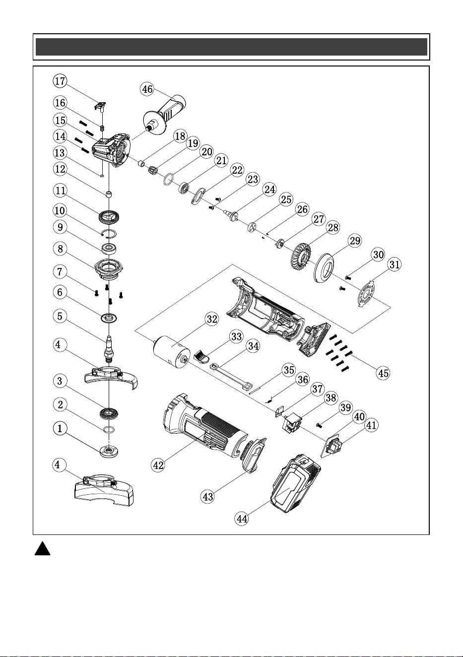
WARNING: When servicing, use only original equipment replacement parts. The use of any
other parts may create a safety hazard or cause damage to the angle grinder.
Any attempt to repair or replace electrical parts on this tool may create a safety hazard unless repairs
are performed by a qualified technician. For more information, call the Toll-free Helpline, at
1-866-349-8665.
!
AVAILABLE PARTS
a
b

26
Key # Part # Part Name
1 2040210006 Outer flange
2 3140070022 Rubber ring
3 2010140054 Inner flange
4a 1270030050 Grinding guard
5 2040050160 Output shaft
4b 1270030053 Cutting guard
6 2030170001 Dust seal
7 4020010189 Screw M4x12
8 2040050160 Front cover
9 4010010078 Bearing 6201-2Z
10 4100010005 Circlip, dia. 32
11 2040110050 Big gear
12 4010020003 Needle bearing HK0810
13 4100040006 Circlip, dia. 7
14 4030010264 Tapping scr ST3.9x19ew
15 2020050086 Head housing
16 2050040061 Spring
17 1160010023 Lock button
18 4010020047 Needle bearing HK0607
19 2040110051 Small gear
20 3140020050 O-type ring
21 4010010043 Bearing 6000-2Z
22 2030160010 Bearing holddown
23 4020020039 Sink screw M4x8
24 1170040082 Connecting shaft
25 3140060012 Connecting disc
26 4020020006 Sink screw ST2.9x8
27 2010230006 Driving disc
28 3150010117 Fan
29 3150050106 Air guiding ring
30 4020010038 Screw M5x8
31 2030030282 Motor flange
32 1030240005 Motor
33 3120120163
Switch button
34 3120110084 Switch lever
35 4130010016 Split pin
36 2050050051 Torsional spring
37 2020230004 Lock out button
38 1062010034 Switch
39 4030010023 Tapping screw ST2.9x8
40 1130030130 PCB
41 3150170032 Contact plate
42 3010190010 Housing
43 3010060023 Foot
44 1290090063
Battery
45 4030010242 Tapping screw ST3.9x16
46 1160020032 Auxiliary handle
AVAILABLE PARTS
Always order by PART NUMBER, not by key number.

2
Rev 2.5 28/08/2025
Distributed by: Menard, Inc., Eau Claire, WI 54703
PERFORMAX
®
20 VOLT ANGLE GRINDER
27
2-YEAR LIMITED WARRANTY:
This PERFORMAX
®
brand power tool carries a 2-Year Limited Warranty to the
original purchaser. If, during normal use, this PERFORMAX
®
power tool breaks
or fails due to a defect in material or workmanship within two (2) years from the
date of original purchase, simply bring this tool with the original sales receipt
back to your nearest MENARDS® retail store. At its discretion, PERFORMAX
®
agrees to have the tool or any defective part(s) repaired or replaced with the
same or similar PERFORMAX
®
product or part free of charge, within the stated
warranty period, when returned by the original purchaser with original sales
receipt. Not withstanding the foregoing, this limited warranty does not cover any
damage that has resulted from abuse or misuse of the Merchandise. This
warranty: (1) excludes expendable parts including but not lim
ited to blades,
brushes, belts, bits, light bulbs, and/or batteries; (2) shall be void if this tool is
used for commercial and/or rental purposes; and (3) does not cover any losses,
injuries to persons/property or costs. This warranty does give you specific legal
rights and you may have other rights, which vary from state to state. Be careful,
tools are dangerous if improperly used or maintained. Seller’s employe
es are
not qualified to advise you on the use of this Merchandise. Any oral
representation(s) made will not be binding on seller or its employees. The rights
under this limited warranty are to the original purchaser of the Merchandise and
may not be transferred to any subsequent owner. This limited warranty is in lieu
of all warranties, expressed or implied including warranties or merchantability
and fitness for a particular
purpose. Seller shall not be liable for any special,
incidental, or consequential damages. The sole exclusive remedy against the
seller will be for the replacement of any defects as provided herein, as long as
the seller is willing or able to replace this product or is willing to refund the
purchase price as provided above. For insurance purposes, seller is not allowed
to demonstrate any of these power tools for you.
For questions / comments, technical assistance, or repair parts –
Please Call Toll Free at: 1-866-349-8665 (M–F 9am – 5pm EST) or email
SAVE YOUR RECEIPTS. THIS WARRANTY IS VOID WITHOUT THEM.