
PRODUCT SPECIFICATIONS
Voltage: 120 volts,60Hz
Current rating: 6.5 Amps
No Load Speed : 11,000/min
Grinding wheel: 4-1/2 inch (115mm)
Need Assistance ?
Call us on our toll free customer support line:
1-866-915-8626 or email us on [email protected]
• Technical questions
• Replacement parts
• Parts missing from package
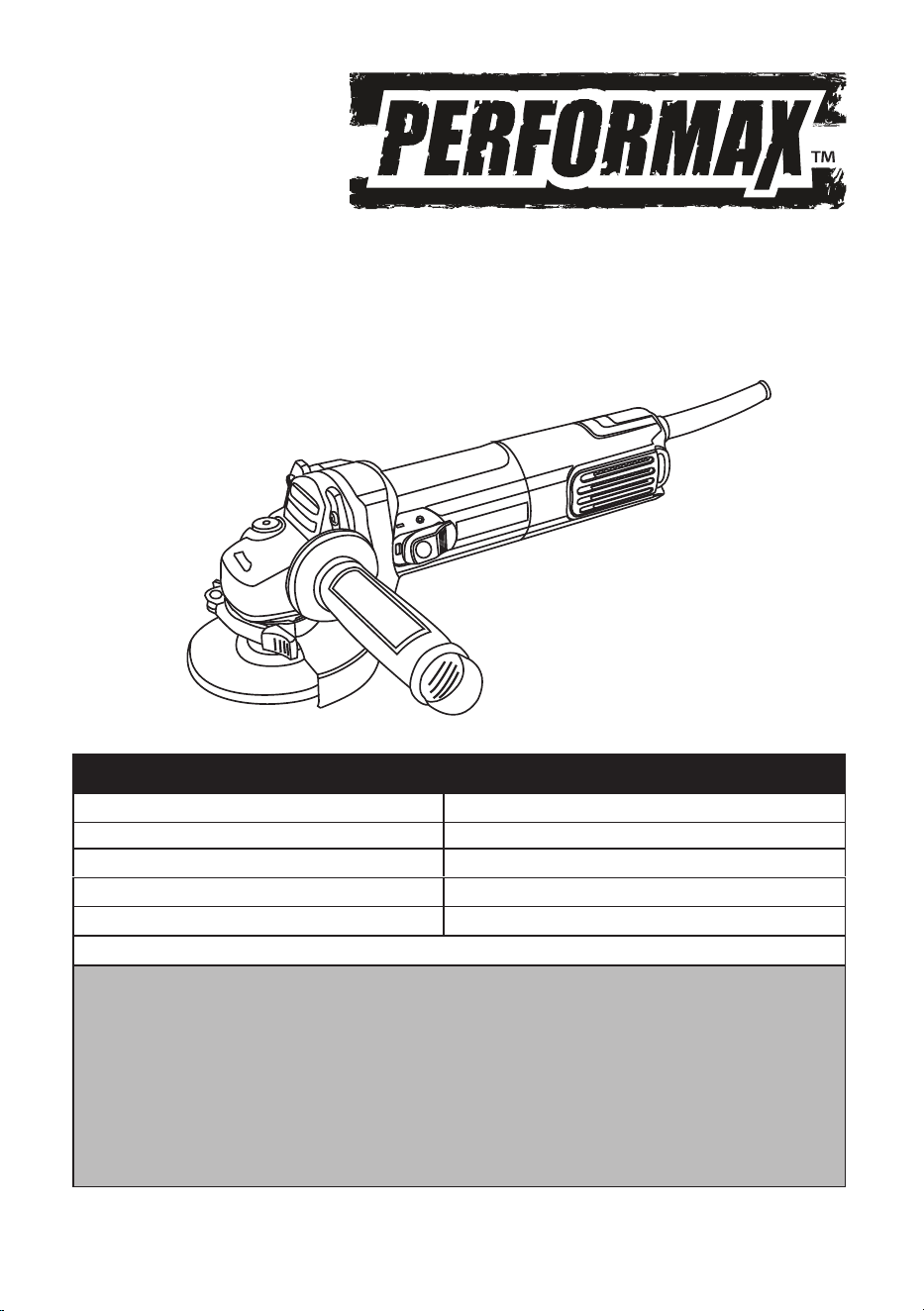
4-1/2" ANGLE GRINDER
241-1000
Owner's Manual
Spindle thread: 5/8"
Double insulated
2
TABLE OF CONTENTS
General Safety Rules.................................................................................... Page 2
Specific Safety Rules................................................................................... Page 4
Symbols....................................................................................................... Page 5
Electrical...................................................................................................... Page 6
Features....................................................................................................... Page 8
Assembly...................................................................................................... Page 8
Operating procedures.................................................................................. Page 9
Maintenance................................................................................................ Page 11
Parts list....................................................................................................... Page 12
Schematic drawing...................................................................................... Page 13
Warranty....................................................................................................... Page 14
GENERAL SAFETY RULES
WARNING :
Remove the plug from the socket before carrying out any adjustment, servicing or
maintenance. Read all safety warnings and all instructions. Failure to follow the
warnings and instructions may result in electric shock, fire and/or serious injury.
Make sure the voltage corresponds to the type label on the unit. Packing materials
are not toys! Children must not play with plastic bags! Danger of suffocation! The
power tool noise output may exceed 85dB(A) at the workplace. In this instance, wear
ear protection.
WARNING :
Read all enclosed safety warnings and instructions.
Failure to follow the warnings and instructions may result in electric shock, fire and/
or serious injury. The term “power tool” in the warnings refers to your power tool or
battery operated (cordless) power tool.
Save all warnings and instructions for future reference.
1) Work area safety
a) Keep work area clean and well lit. Cluttered or dark areas invite accidents.
-
uids, gases or dust. Power tools create sparks which may ignite the dust or fumes.
c) Keep children and bystanders away while operating a power tool. Distractions can cause you to
lose control.
2) Electrical safety
a) Power tool plugs must match the outlet. Never modify the plug in any way. Do not use any adapter

3
b) Avoid body contact with grounded surfaces, such as pipes, radiators, ranges and refrigerators.
There is an increased risk of electric shock if your body is grounded.
c) Do not expose power tools to rain or wet conditions. Water entering a power tool will increase the
risk of electric shock.
d) Do not abuse the cord. Never use the cord for carrying, pulling or unplugging the power tool. Keep
cord away from heat, oil, sharp edges and moving parts. Damaged or entangled cords increase the
risk of electric shock.
e) When operating a power tool outdoors, use an extension cord suitable for outdoor use. Use of a
cord suitable for outdoor use reduces the risk of electric shock.
f) If operating a power tool in a damp location is unavoidable, use a residual current device (RCD) pro-
tected supply. Use of an RCD reduces the risk of electric shock.
3) Personal safety
a) Stay alert, watch what you are doing and use common sense when operating a power tool. Do not
use a power tool while you are tired or under the influence of drugs,
alcohol or medication. A moment
of inattention while operating power tools may result in serious personal injury.
b) Use personal protective equipment. Always wear eye protection. Protective equipment such as
dust mask, non-skid safety shoes, hard hat, or hearing protection used for appropriate conditions will
reduce personal injuries.
c) Prevent unintentional starting. Ensure the switch is in the off-position before connecting to power
the switch or energizing power tools that have the switch on invites accidents.
d) Remove any adjusting key or wrench before turning on the power tool. A wrench or a key left
attached to a rotating part of the power tool may result in personal injury.
e) Do not overreach. Keep proper footing and balance at all times. This enables better control of the
power tool in unexpected situations.
f) Dress properly. Do not wear loose clothing or jewelry. Keep your hair, clothing and gloves away
from moving parts. Loose clothes, jewelry or long hair can be caught in moving parts.
g) If devices are provided for the connection of dust extraction and collection facilities, ensure these
are connected and properly used. Use of dust collection can reduce dust-related hazards.
4) Power tool use and care
a) Do not force the power tool. Use the correct power tool for your application. The correct power tool
will do the job better and safer at the rate for which it was designed.
b) Do not use the power tool if the switch does not turn it on and off. Any power tool that cannot be
controlled with the switch is dangerous and must be repaired.
c) Disconnect the plug from the power source and/or the battery pack from the power
tool before
making any adjustments, changing accessories, or storing power tools. Such preventive safety mea-
sures reduce the risk of starting the power tool accidentally.
d) Store idle power tools out of the reach of children and do not allow persons unfamiliar with the
power tool or these instructions to operate the power tool. Power tools are dangerous in the hands of
untrained users.
plugs with grounded power tools. Unmodified plugs and matching outlets will reduce risk of electric
shock.
4
e) Maintain power tools. Check for misalignment or binding of moving parts, breakage of parts and
any other condition that may affect the power tool’s operation. If damaged, have the power tool
repaired before use. Many accidents are caused by poorly maintained power tools.
f) Keep cutting tools sharp and clean. Properly maintained cutting tools with sharp cutting edges are
less likely to bind and are easier to control.
g) Use the power tool, accessories and tool bits etc. in accordance with these instructions, taking into
account the working conditions and the work to be performed. Use of the power tool for operations
different from those intended could result in a hazardous situation.
5) Service
This will ensure that the safety of the power tool is maintained.
b) When servicing a power tool, use only identical replacement parts. Follow instructions in the Main-
tenance section of this manual. Use of unauthorized parts or failure to follow Maintenance instruc-
tions may create a risk of shock or injury.
WARNING :
To reduce the risk of injury, user must read the instruction manual.
SPECIFIC SAFETY RULES
• Hold the power tool only by the insulated gripping surfaces when performing an operation where
the accessory may contact hidden wiring or its own power cord. Cutting accessory contacting a “live”
wire may make exposed metal parts of the power tool “live” and could give the operator an electric
shock
• Know your power tool. Read operator’s manual carefully. Learn its applications and limitations, as
• Always wear safety glasses. Everyday eyeglasses have only impact-resistant lenses; they are NOT
safety glasses. Following this rule will reduce the risk of serious personal injury.
• Protect your lungs. Wear a face or dust mask if the operation is dusty. Following this rule will re-
duce the risk of serious personal injury.
• Protect your hearing. Wear hearing protection during extended periods of operation. Following this
rule will reduce the risk of serious personal injury.
• Inspect tool cords periodically and, if damaged, have repaired at your nearest authorized service
center. Constantly stay aware of cord location. Following this rule will reduce the risk of electric
• Check damaged parts. Before further use of the tool, a guard or other part that is damaged should
be carefully checked to determine that it will operate properly and perform its intended function. Fol-

5
• Check for alignment of moving parts, binding of moving parts, breakage of parts, mounting, and any
other conditions that may affect its operation. A guard or other part that is damaged should be prop-
erly repaired or replaced by an authorized service center. Following this rule will reduce the risk of
• Make sure your extension cord is in good condition. When using an extension cord, be sure to use
one heavy enough to carry the current your product will draw. A wire gauge size (A.W.G.) of at least
14 is recommended for an extension cord 50 feet or less in length. A cord exceeding 100 feet is not
recommended. If in doubt, use the next heavier gauge. The smaller the gauge number, the heavier the
cord. An undersized cord will cause a drop in line voltage resulting in loss of power and overheating.
• Inspect for and remove all nails from lumber before using this tool. Following this rule will reduce
the risk of serious personal injury.
• Save these instructions. Refer to them frequently and use them to instruct others who may use this
tool. If you loan someone this tool, loan them these instructions as well.
WARNING :
Some dust created by power sanding, sawing, grinding, drilling, and other
construction activities contain chemicals known to cause cancer, birth defects or
other reproductive harm. Some examples of these chemicals are:
• lead from lead-based paints,
• crystalline silica from bricks and cement and other masonry products, and
• arsenic and chromium from chemically-treated lumber.
Your risk from these exposures varies, depending on how often you do this type of
work. To reduce your exposure to these chemicals, work in a well ventilated area, and
work with approved safety equipment, such as those dust masks that are specially
designed to filter out microscopic particles.
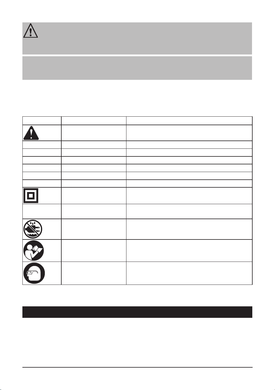
SYMBOLS
The following signal words and meanings are intended to explain the levels of risk associated with this product.
WARNING :
Indicates an imminently hazardous situation, which, if not avoided, will result in
death or serious injury.
6
CAUTION :
Indicates a potentially hazardous situation, which, if not avoided, may result in minor
or moderate injury.
CAUTION :
(Without Safety Alert Symbol) Indicates a situation that may result in property
damage.
Some of the following symbols may be used on this product. Please study them and learn their
meaning. Proper interpretation of these symbols will allow you to operate the product better and
safer.
Symbol
Description DESIGNATION/EXPLANATION
Safety Alert Indicates a potential personal
injury hazard.
V Volts Voltage
A Amperes Current
Hz Hertz Frequency (cycles per second)
min Minutes Time
~ Alternating Current Type of current
No No Load Speed Rotational speed, at no load
Class II Tool Double-insulated construction
.../min Per Minute Revolutions, strokes, surface speed, orbits etc., per
minute
Wet Conditions Alert Do not expose to rain or use
in damp locations.
Read the operater's manual To reduce the risk of injury, user must read and
understand operator’s manual before using this
product.
Eye Protection Always wear eye protection with
side shields marked to comply
with ANSI Z87.1.
ELECTRICAL
DOUBLE INSULATION
Double insulation is a concept in safety in electric power tools, which eliminates the need for the
usual three-wire grounded power cord. All exposed metal parts are isolated from the internal metal
motor components with protecting insulation. Double insulated tools do not need to be grounded.

7
WARNING :
The double insulated system is intended to protect the user from shock resulting
from a break in the tool’s internal wiring. Observe all normal safety precautions to
avoid electrical shock.
NOTE :
Servicing of a tool with double insulation requires extreme care and knowledge
of the system and should be performed only by a qualified service technician. For
service, we suggest you return the tool to your nearest authorized service center for
repair. Always use original factory replacement parts when servicing.
ELECTRIC CONNECTION
This tool has a precision-built electric motor. It should be connected to a power supply that is 120
volts, 60 Hz, AC only (normal household current). Do not operate this tool on direct current (DC). A
substantial voltage drop will cause a loss of power and the motor will overheat. If your tool does not
operate when plugged into an outlet, double-check the power supply.
EXTENSION CORDS
When using a power tool at a considerable distance from a power source, be sure to use an extension
cord that has the capacity to handle the current the tool will draw. An undersized cord will cause a
drop in line voltage, resulting in overheating and loss of p
ower. Use the chart to determine the mini-
mum wire size required in an extension cord. Only round jacketed cords listed by Underwriter’s Labo-
ratories (UL) should be used.
When working outdoors with a tool, use an extension cord that is designed for outside use. This type
of cord is designated with “WA” or “W” on the cord’s jacket.
Before using any extension cord, inspect it for loose or exposed wires and cut or worn insulation.
** Ampere rating ( on faceplate )
0 ~ 2 2.1 ~ 3.4 3.5 ~ 5 5.1 ~ 7 7.1 ~ 12 12.1 ~ 16
Cord length
Wire size according A.W.G. ( Amercian wire gauge )
25'
16 16 16 16 14 14
50'
16 16 16 14 14 12
100'
16 16 14 12 10 -
Table 1 : minimum wire size required in an extension cord.
**Used on 12 gauge - 20 amp circuit.
WARNING :
Keep the extension cord clear of the working area. Position the cord so that it will
not get caught on lumber, tools or other obstructions while you are working with a
power tool. Failure to do so can result in serious personal injury.
8
WARNING :
Check extension cords before each use. If damaged, replace immediately. Never use
tool with a damaged cord since touching the damaged area could cause electrical
shock resulting in serious injury.
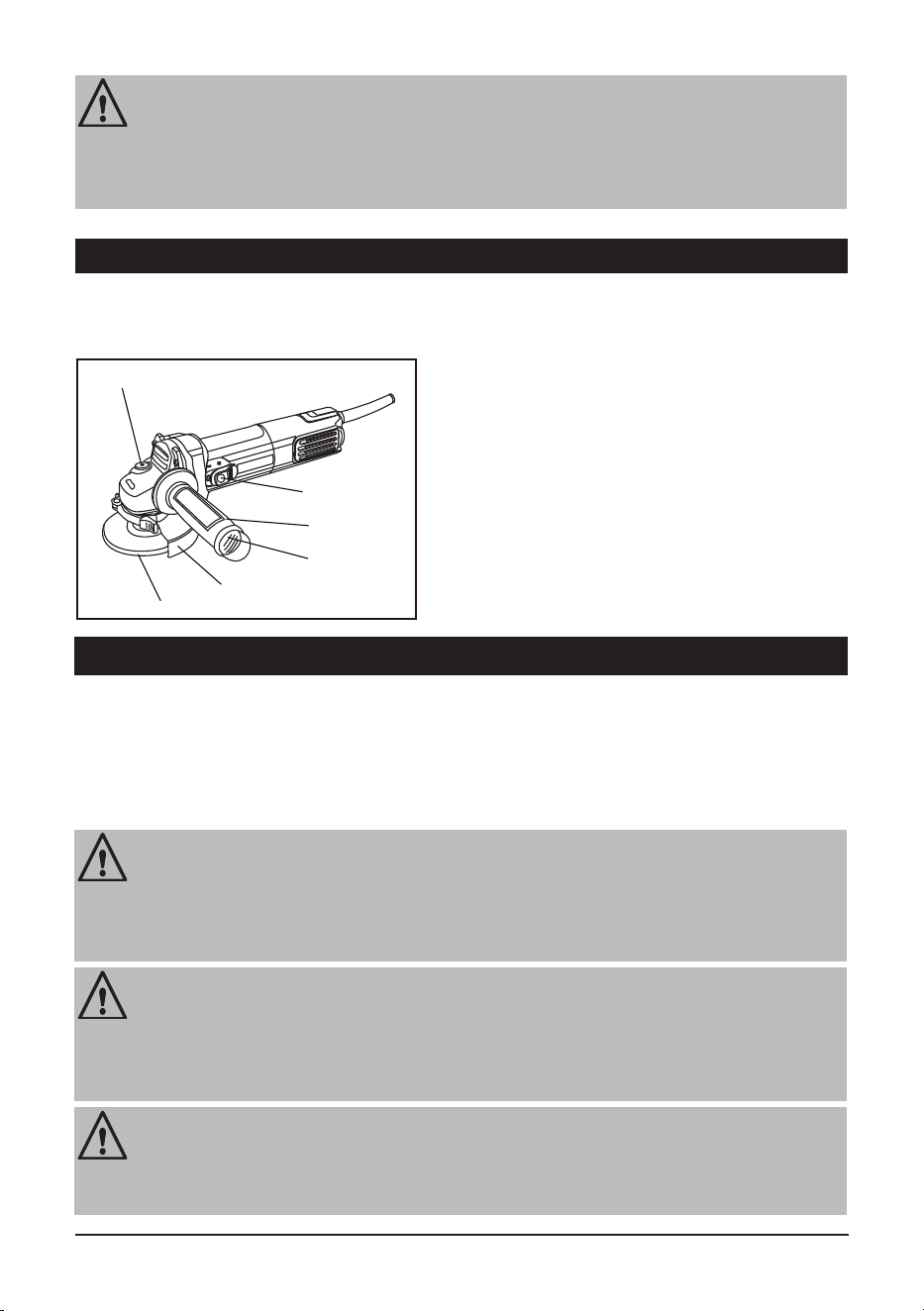
FEATURES
FUNCTIONAL DESCRIPTION
Before attempting to use this product, familiarize yourself with all operating features and safety rules.
Fig. 1
2. Spindle lock
4. Wheel guard
5. Side handle
3. Wheel Accessory – Not Included
1. On/off switch
1
2
4
3
5
ASSEMBLY
CONTENT OF PACKING
WARNING :
If any parts are damaged or missing do not operate this product until the parts are
replaced. Use of this product with damaged or missing parts could result in serious
personal injury.
WARNING :
Do not attempt to modify this tool or create accessories not recommended for use
with this tool. Any such alteration or modification is misuse and could result in a
hazardous condition leading to possible serious personal injury.
WARNING :
Do not connect to power supply until assembly is complete. Failure to comply could
result in accidental starting and possible serious personal injury.
1 x Side handle
6. Spanner
6
1 x Spanner
1 x grinding guard
1 x cutting guard
OPERATING PROCEDURES
9
A
B1
B2
B3
B4
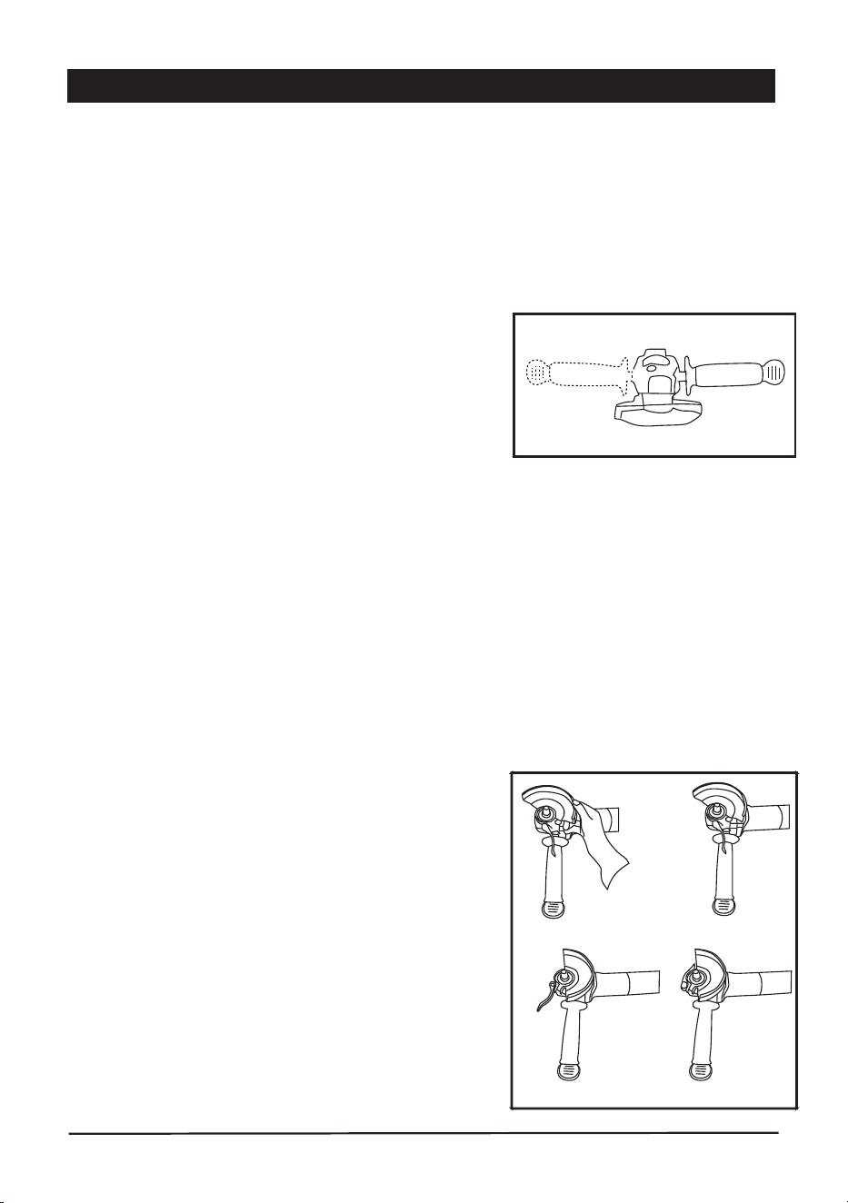
Side Handle
Using Grinding Guards and Cutting Guards
Grinding Guard (for grinding wheels only)
This angle grinder is designed to accept accessories with a 5/8”-11 arbor as well as accessories with
a 7/8” bore. Check to ensure that any discs used on this machine are rated for the 11,000 rpm speed
of this grinder. Check also for any damage to an abrasive disc before installing. Any disc that is cracked,
has been dropped, or subjected to other damage due to temperature extremes or solvents should be
discarded. A damaged disc can fly apart in use and may cause serious injury to the operator or
bystanders.
■ Designed for use withgrinding wheels, wire brushes, and flap discs.
■ Not for use with cutting wheels.
■ Provides protection duringcoarse or standard grinding tasks.
Grinding and Cut-off Wheels
■ The auxiliary side handle for the grinder may be mounted
on either the left or right side of the tool.
■ Unplug the grinder.
■ Screw the handle firmly into the threaded hole on either
side of the metal grinding head.
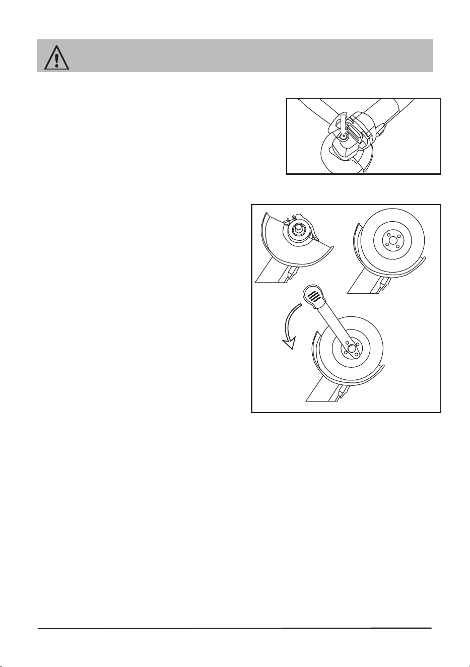
Cutting Guard (for cutting wheels only)
■ Must always be installed when usingcutting wheels.
■ Cutting wheels are thinner than grinding wheels and can break if the grinder is misused
(for example, twisting or skewing the tool).
■ The cutting guard offersincreased protection against wheel breakage.
Important Safety Notes:
■ Always use the correct guard for the wheel you are
operating.
■ Never use a cutting wheel without a cutting guard.
■ The closed side of the guard should always face the
operator for maximum protection.
Installing a Wheel Guard:
1. Open the guard clamping lever. Place the guard firmly
onto the tool head. (See Fig. B1)
2. Align the guard grooves with the spindle grooves and
rotate to the desired position. (See Fig. B2, B3)
3. Close the clamping lever to lock the guard in place.
(See Fig. B4)
10
Always unplug the tool before attaching any accessories.
WARNING :
Installing a grinding wheel or cutting disc
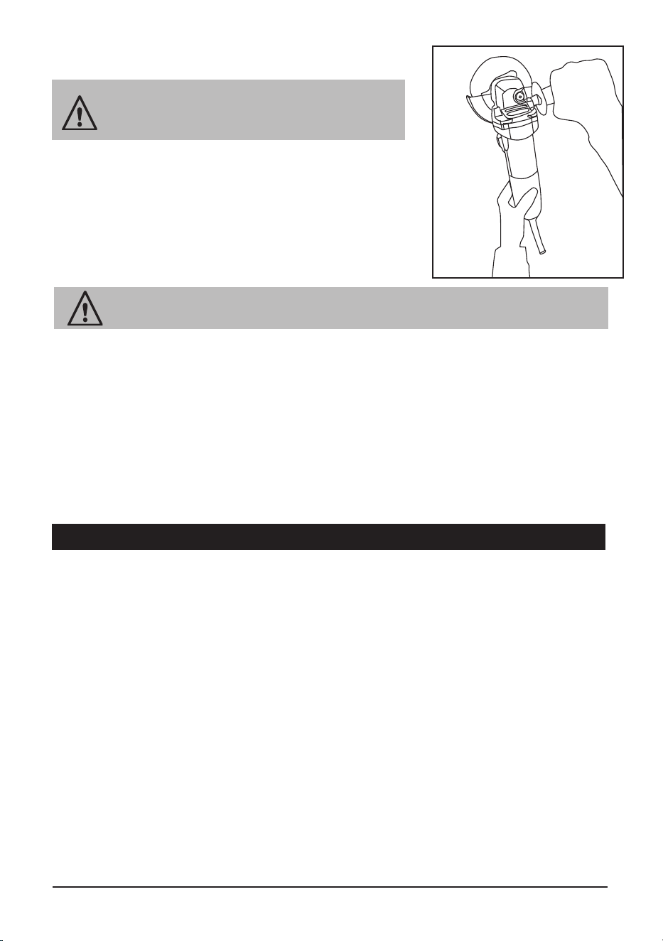
SPINDLE LOCKING BUTTON (See Figure C)
Clean the grinder spindle and all parts to be mounted.
For clamping and loosening the grinding tools, lock the
grinder spindle by pressing the lock button and turn
the spindle till the spindle lock button
snaps into a lock position.
Remove a Disc
■ Unscrew(counterclockwise) the outer flange with
the provided spanner. (See Figure D3)
■
Remove the disc from the tool spindle and inner flange
Install a disc
■
Place the inner flange onto the spindle.(See Figure D1)
■ Place the disc on the tool spindle and inner flange.
■ Ensure it is correctly positioned.
■
Pay attention to the dimensions of the grinding disc.
■ The mounting hole diameter must fit the inner
flange without play.
■ Do not use reducers or adapters.
■ When using a diamond cutting disc, take care that
the direction-of-rotation arrow on the diamond
cutting disc and the direction of rotation on the
machine (direction-of-rotation arrow on the
machine head) agree. (See Figure D2)
■
Screw on the outer flange with the provided spanner.
(See Figure D3)
D1
D2
D3
Loose the
outer flange
Actuate the Spindle Locking Button only when the grinder spindle is at a standstill!
C
■ Plug in the tool.
■ Hold the tool firmly with one hand on the side handle and the
other gripping the housing.
■ Check to make sure the abrasive disc is not obstructed.
■ Slide the switch on the left side of the machine forward with
your thumb.
■ Switching the tool on or off under load will damage the switch.
■ To turn the tool off, slide the switch back.
Turn off your tool at once, unplug and inspect it for serious problems if:
■ Moving parts get stuck ■ Speed drops to an abnormally low level
■ The motor housing gets hot ■ Sparks or odors emit from the casing
Running the TOOL
WARNING :
Actuate the spindle locking button only
when the grinder spindle is at a standstill!
WARNING :
11
E
MAINTENANCE
Check the brushes occasionally (after about 60 hours of use) and replace if worn. Unplug the tool.
Unscrew the round brush covers on each side of the
body and pull the brushes out to check or replace them. If you replace the brushes, run the tool
without load for 15 minutes to seat the brushes properly.
Keep the vents clear of dust and debris. This will help prevent possible electrical shorts and ensure
proper cooling.
Keep the tool housing and handle clean and free of oil and grease by using mild soap and a
damp (not wet) cloth.
Avoid overloading your grinder. It will become hot and lose efficiency. Running it free of load for a
minute or two will allow it to cool itself to normal temperature.
Inspect the cord regularly and have it replaced by an authorized repair facility if it is damaged.
Lubrication for this tool is done at the factory and should not be necessary again under normal use.
Check the grinding disc regularly for cracking and other damage. Do not use a damaged disc.
An authorized repair center should do any repair, modification, or maintenance that involve
disassembling the grinder.
Any damage to the tool should be corrected at an authorized repair center.

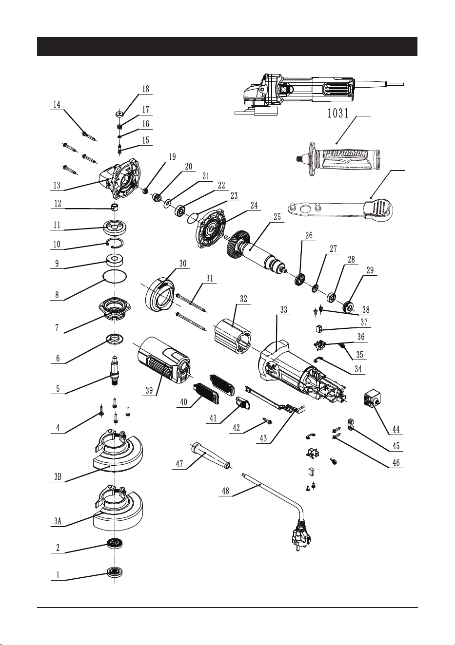
PARTS LIST
12
No. Description Qty No. Description Qty
1 inner flange 1 27 ringφ17*φ7.1*0.4 1
2 outter flange 1 28 bearing 607 1
3A quick change grinding disc wheel guard 1 29 bearing sleeve 1
3B quick change cutting disc wheel guard 1 30 windshield 1
4 screw M4X13 4 31 screw ST4x75 2
5 output shaft 1 32 stator 1
6 dustproof cover 1 33 housing 1
7 front cover 1 34 insulatingsheet 2
8 ringφ40*φ1 1 35 coil spring 2
9 6201 bearing 1 36 brush holder 2
10 circlip for holeφ32 1 37 carbon brush 2
11 gear wheel 1 38 screw ST3x7.5 4
12 needle bearing 1 39 rear cover 1
13 gear box 1 40 Sidecover 2
14 screwST M4x28 4 41 pushing block 1
15 self-lock pin 1 42 screw ST4x14 1
16 ringφ6*φ4*φ1 1 43 pushing rod 1
17 self-lock spring 1 44 switch 1
18 self-lock pin cap 1 45 pressure plate 1
19 nut M6 1 46 screw ST4x14 2
20 pinion 1 47 cable protector 1
21 ringφ19.2*φ6.1*0.2 1 48 cable 1
22 bearing 608 1 49 side handle 1
23 ringφ29.4*φ0.75 1 50 spanner 1
24 middle plate 1
25 armature 1
26 dustproof cover 1
13
SCHEMATIC DRAWING
49
50

14
For questions / comment
s, technical assistance or repair parts –
Please call toll free at: 1-866-915-8626 (M-F 8am - 6pm) or
send email to [email protected].
SAVE YOUR RECEIPTS. THIS WARRANTYY IS VOID WITHOUTT THEM.
Distributed by: Menard, Inc., Eau Claire, WI 54703
PERFORMAX
TM
4-1/2" ANGLE GRINDER WARRANTY
2-YEAR LIMITED WARRANTY:
This PERFORMAX brand power tool carries a 2-Year Limited Warranty to the
original purchaser. If, during normal use, this PERFORMAX power tool breaks
or fails due to a defect in material or workmanship within two (2) years from the
date of original purchase, simply bring this tool with the original sales receipt
back to your nearest MENARDS retail store. At its discretion, PERFORMAX
agrees to have the tool or any defective part(s) repaired or replaced with the
same or similar PERFORMAX product or part free of charge, within the stated
warranty period, when returned by the original purchaser with original sales
receipt. Notwithstanding the foregoing, this limited warranty does not cover any
damage that has resulted from abuse or misuse of the Merchandise. This
warranty: (1) excludes expendable parts including but not limited to driver blades,
O rings, blades, brushes, belts, bits, light bulbs, and/or batteries; (2) shall be void
if this tool is used for commercial and/or rental purposes; and (3) does not cover
any losses, injuries to persons/property or costs. This warranty does give you
specific legal rights and you may have other rights, which vary from state to
state. Be careful, tools are dangerous if improperly used or maintained. Seller’s
employees are not qualified to advise you on the use of this Merchandise. Any
oral representation(s) made will not be binding on seller or its employees. The
rights under this limited warranty are to the original purchaser of the Merchandise
and may not be transferred to any subsequent owner. This limited warranty is in
lieu of all warranties, expressed or implied including warranties or merchantability
and fitness for a particular purpose. Seller shall not be liable for any special,
incidental, or consequential damages. The sole exclusive remedy against the
seller will be for the replacement of any defects as provided herein, as long as
the seller is willing or able to replace this product or is willing to refund the
purchase price as provided above. For insurance purposes, seller is not allowed
to demonstrate any of these power tools for you.
TM
TM
®
TM
TM